 少量のバッチ、高い基準。私たちの迅速なプロトタイピングサービスにより、検証がより速く簡単になります——

溶接部の気孔の原因とは?ビードを読み取り、再作業を防止しましょう
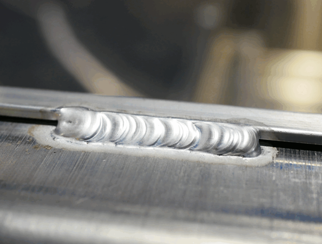
溶接における気孔とは何か?
「溶接における気孔の原因は何か?」という質問に直接お答えするなら、 溶接における気孔の原因 通常、溶融した溶接金属が完全に凝固する前に、ガスがその中に閉じ込められることに起因します。この閉じ込められたガスにより、溶接部に小さな空洞、ピンホール、または空隙が生じます。平易な言葉で言えば、「溶接における気孔を定義せよ」と言われた場合、それは表面に現れることもあれば、表面下に隠れて存在することもある、ガス関連の溶接欠陥です。 溶接における気孔の定義 、それは表面に現れることもあれば、表面下に隠れて存在することもある、ガス関連の溶接欠陥です。
気孔とは、金属が冷却・硬化する際に溶接部内部に閉じ込められたガスのことです。
TWIによる技術的ガイドラインでは、気孔とは、溶融プールから放出されたガスが凝固中の金属内に凍結(固化)して形成される空洞であると説明しています。 製造業者 また、丸い穴状の欠陥が目視で確認されやすい一方で、細長い欠陥は「ワームホール」や「パイピング」として現れる場合があるとも指摘しています。
溶接における気孔の意味
初心者が尋ねる「 溶接における多孔性(ポロシティ)とは何か?」 という問いに対しては、これを本来金属が充填されるべき場所に存在する空隙(空洞)であると捉えてください。これらの空洞は重要です。なぜなら、有効な溶接面積を減少させ、外観を損ない、漏れの経路を作り出し、適用される規格および使用条件に応じて追加の研磨、補修、あるいは不合格判定を招く可能性があるからです。表面の気孔は、必ずしも単なる外観上の問題ではありません。ある種の作業では、目視可能な気孔が、溶接部内部のより広範囲にわたるガス捕獲を示唆していることがあります。
なぜ捕 trapped ガスが弱い箇所を生じるのか
より技術的に言えば、気孔は、窒素、酸素、または水素が溶接プール内に侵入し、十分な時間内に排出されない場合に形成される。不適切なシールドガスによる保護は、空気をアーク領域内に流入させることを許容する。油、グリース、塗料、錆、プライマー、亜鉛めっきなどの汚染物質は、加熱時にガスを発生させる可能性がある。被加工材、フィラー材、電極、またはフラックス上の水分は、水素の混入リスクを高める。不安定な溶接技術、ノズル距離の過大化、ガス流量の過剰な乱流、あるいは気流(ドラフト)なども、シールドガスによる保護を妨げる要因となる。TWI(The Welding Institute)によれば、シールドガス中にわずか約1%の空気が混入しただけでも、分散型気孔が発生する可能性がある。
- シールドガスのカバーリング喪失
- 汚染または被覆された母材
- 消耗品または継手部に存在する水分
- ガス流量の問題、漏れ、または気流(ドラフト)
- 溶接プールを不安定化させる溶接技術
これらの気孔のパターンおよび位置は、単に「気孔」という欠陥名よりも多くの情報を示すことが多く、そのためビードそのものが最初の診断手がかりとなる。
溶接気孔の種類とそれが示唆するもの
多孔質ビーズは、見た目が本当にランダムであることはめったにありません。気孔の大きさ、間隔、位置は、アークゾーンで何が変化したかを示す最初の手がかりとなります。そのため、誰かがノブを回し始めたり、単にガス流量の問題だと決めつけたりする前に、視覚診断が有効です。 溶接部の気孔の種類 たとえ欠陥の名称が似ていても、それぞれ異なる最初の点検項目を示唆することがよくあります。
代表的な気孔パターンとその原因の推定
ビーズを地図のように活用しましょう。表面に見えるものだけでは原因を確定的に証明することはできませんが、原因の範囲を素早く絞り込むのに役立ちます。
| 外観上の特徴 | 考えられる根本原因 | 最初の点検ポイント | 考えられる是正措置 |
|---|---|---|---|
| ビーズに沿ってランダムに散在・分布する気孔 | 遮蔽ガスの断続的な喪失、軽微な汚染、水分、遮蔽ガスの不均一な供給 | ノズルの状態、ガス流路、ジョイントおよびフィラーの最近の清掃状況 | 一貫したシールドガスを復元し、汚染物質を除去し、溶接部に気流が当たらないようにする |
| 短い範囲内に集中して発生する気孔群 | 局所的な油分、グリース、錆、プライマー、またはワイヤーやフィラーの汚染された部分 | 気孔が集まって発生する正確な部位 | 当該部位を再清掃し、汚染された消耗品を切断して交換し、事前準備後に再溶接する |
| 溶接終端部におけるクレータ気孔またはクレータパイプ | アークを急停止させたこと、急速な凝固、終端部へのフィラー供給不足 | 溶接終端技術およびクレータ充填の練習 | クレータを充填し、アークを徐々に遮断(ターミネーション・スロープダウン)する。必要に応じてスロープダウン機能やランオフ・タブを活用する |
| ビード全体にわたって均一に繰り返されるピンホール | 体系的なガス流量の問題、再発する汚染、空気の巻き込み | ガス流量の安定性、ホースの漏れ、スパッタで詰まったノズル、作業場内の気流 | 被覆の均一化を図り、乱流を低減し、ノズル部品を清掃または交換する |
| 表面に開口した凹坑またはピンホールとして目視可能な表面気孔 | しばしばより深刻な分散気孔、コーティングの影響、あるいは重大なシールド不具合と関連している | ビード表面、近接するコーティング、およびシールドの均一性 | 単なる外観上の問題と見過ごさず、修復前にその範囲を確認し、原因を是正すること |
| 放射線検査(RT)または超音波検査(UT)によって検出された内部欠陥 | 同じ汚染、水分、またはシールド不具合により表面下に閉じ込められたガス | 手順の遵守状況、消耗品の状態、遮蔽履歴 | NDTで範囲を確認し、手順に従って修復し、再溶接前に発生源を除去する |
| ワームホール(虫食い状の孔)または細長いトンネル状の気孔 | 著しい汚染、厚塗りの塗料またはプライマー、継目や閉じた接合部に閉じ込められたガス | 継手形状、コーティング厚さ、継手線近傍の汚染 | 溶接部から汚染物を除去し、ガス発生性のコーティングを減らし、組立精度を再検討する |
| 溶接線に沿って連続する線状気孔または細長い気孔 | 繰り返し発生するガス漏れ、連続した汚染された継ぎ目、再発する溶接技術またはパラメータの不均衡 | 欠陥が継ぎ目を一定の直線状に追っているかどうか | 繰り返し発生する原因を修復し、継ぎ目を再清掃し、再発する溶接技術上の問題を是正する |
表面の気孔が、より深い溶接部の問題を示唆していること
目に見えるピンホールは簡単に発見できますが、これは便利な点ではありますが、早急に軽視してはなりません。TWIのガイドラインによると、表面に開口する気孔は通常、広範囲に分散した気孔の存在を示しています。平易な言い方をすれば、ガスが表面まで到達したということは、その直下にもさらに多くのガスが閉じ込められている可能性があるということです。そのため、表面気孔は単なる外観上の問題ではなく、品質上の警告サインとなるのです。
隠れた気孔は状況をさらに複雑にします。放射線検査(RT)および超音波検査(UT)は、内部気孔を検出するために一般的に用いられる手法であり、TWIでは、気孔の特性評価においては放射線検査の方が一般に優れていると指摘しています。ビードの外観が許容範囲内であっても、検査で丸みを帯びた空洞が確認された場合、原因究明の調査は通常、以下の要因に帰結します:シールドガスの不適切な使用、異物混入、水分、あるいは溶融池の凝固速度の速さ。
ワームホール欠陥および線状気孔が診断を変えるとき
ランハイ社製の 溶接におけるワームホール欠陥 その形状が診断に影響を与えるため重要です。孤立したガス孔が少数ある場合とは異なり、ワームホールは、溶接金属の凝固時に生成され閉じ込められたガスの体積がより大きいことを示唆しています。TWIでは、ワームホールを、表面の著しい汚染、厚塗りのペイントまたはプライマー、およびガスがより容易に閉じ込められる隙間状の継手条件(特にフィレット溶接されたT字継手)と関連付けています。
直線状気孔 別の方向を示しています。気孔が直線上に並ぶ場合、あるいは パイピング気孔 が溶接方向に沿って延長した特徴を示す場合、その問題はランダムではなく、繰り返し発生する傾向があります。継手の一部区間における母材が汚染されているか、あるいはパス全体で遮蔽ガスが同様の方法で妨げられている可能性があります。「パターン・カタログ」では、 Xiris 直線状気孔およびワームホール状気孔を、一貫した工程上の不具合、汚染、およびガス被覆不良と関連付けています。
これは、ビードの気孔パターンを読むことの真の価値です。パターンによって原因の範囲は絞られますが、それでも依然として複数の可能性のある原因経路が残り、また気孔はしばしばそれらのうち複数が同時に作用して生じます。
すべての溶接プロセスに共通する溶接部気孔の原因
気孔のパターンが正しい方向性を示した後、本格的な原因究明作業が始まります。ほとんどの溶接方法において、 溶接部気孔の原因 は通常、以下の4つの大カテゴリーに分類されます:母材の汚染、保護ガスの被覆不良、湿気を含んだまたは劣化した消耗品、および周囲環境による干渉です。実際には、これらはしばしば重複して発生します。たとえば、継手にわずかに油分が付着していたこと、ノズルにスパッタが堆積していたこと、さらに作業エリア上空をファンの風が通過していたこと——こうした要因が同時に重なって、ビードに気孔が現れることがあります。そのため、賢いトラブルシューティングでは、大きなパラメーター変更を行う前に、まず基本的な点検から始めます。
溶融金属池内にガスを閉じ込める汚染
汚染は、気孔発生の最も一般的な 原因の一つです 塗料、グリース、油、接着剤、錆、圧延スケール、めっき残渣、または水分がアークによって加熱されると、溶融プール内にガスを放出することがあります。製造業者は特に、圧延スケールや錆の上での溶接により分解ガスが発生すること、および亜鉛などのコーティングが急速に蒸発して激しいガス放出を引き起こすことに注意しています。
- 溶接部近傍に塗料、プライマー、油、グリース、接着剤、錆、および圧延スケールがないか確認してください。
- 被加工物だけではなく、充填ワイヤーの汚染、GTAW用充填材の汚染、さらには手袋の汚れなども不純物の原因となる可能性があるため、それらにも注意してください。
- アンチスパッタ剤の使用状況を確認してください。過剰な使用は加熱により気化し、溶融プールを汚染する可能性があります。
- 気孔が局所的に発生している場合は、まずその接合部の該当箇所を点検し、溶接手順全体を変更する前に原因を特定してください。
ガス流量および気流(ドロフト)によるシールド失敗
沢山 溶接における気孔の原因 遮蔽性能の低下に戻るが、必ずしも明らかなかたちで現れるわけではない。空のシリンダー、曲がったホース、損傷したOリング、焼けたホース、汚染されたガス配管、詰まったノズル、または漏れのある接続部など、いずれも保護性能を低下させる要因となる。また、ガス流量が高すぎると乱流が生じ、周囲の空気が溶接部に流入してしまう場合があり、これは「OTC DAIHEN」と『The Fabricator』のガイドラインの両方で言及されている問題である。 OTC DAIHEN および『The Fabricator』のガイドラインで述べられている。
- シリンダーが空でないことを確認する。
- ホースに切り傷、曲がり、挟み込み、または汚染がないか点検する。
- ノズル開口部にスパッタによる詰まりや制限がないか確認する。
- ガス被覆が不均一に感じられる場合、トーチまたはガンの位置を確認する。
- 裏面から空気が流入する可能性のある開放根元や継手ギャップに注意する。
水分・消耗品および表面処理の誤り
湿気は見落とされやすく、問題が発生してからでないと原因として認識されないことがよくあります。湿った被覆アーク溶接棒(SMAW電極)、フラックス入りワイヤの不具合、サブマージド・アーク・ウェルディング(SAW)用フラックスへの湿気吸収、低温の鋼板表面への結露、あるいは溶接継手部への水の付着など、いずれも溶接部にガスを混入させる原因となります。『The Fabricator』誌によると、SMAW電極、FCAW用消耗材、およびSAW用フラックスは、保管状態が不適切な場合、湿気を吸収する可能性があります。このため、消耗材の状態は、母材の清掃と同様に重要です。
- 溶接前に、継手部が清潔かつ乾燥していることを確認してください。
- シフト間における電極、ワイヤ、およびフラックスの保管方法を再確認してください。
- 電圧や電流を変更する前に、溶接材の状態を点検してください。
- 厚肉材、ラップ継手、または低温環境から持ち込まれた金属表面に結露がないか確認してください。
- 保護ガスのカバーを乱す可能性のあるファン、開放されたドア、および周辺の空気の流れを確認してください。
これらは、溶接における気孔の主な原因となる普遍的な経路です 溶接気孔の主な原因 。ただし、各溶接プロセスではこれらの要因が異なる形で顕在化するため、ビード上に現れる同一の気孔でも、GMAWではある意味をもち、GTAW、SMAW、またはFCAWでは別の意味を持つことがあります。
MIG溶接およびその他の溶接プロセスにおける気孔
丸みを帯びた気孔はビード上で見た目が同じように見えても、その発生メカニズムによって原因の診断は異なります。そのため、 mIG溶接における気孔 は、TIG溶接、被覆アーク溶接(スタック溶接)、フラックスコアド溶接、またはサブマージドアーク溶接における気孔と同様の方法で対処してはなりません。最も迅速なトラブルシューティングの第一歩は、まず欠陥の種類を溶接プロセスに照合することです。各溶接法では、溶融プールの保護方法、使用される消耗品が異なり、それぞれ特有の予測可能な箇所で不具合が発生しやすくなります。
MIG溶接で気孔が生じやすい理由
GMAW(ガス金属アーク溶接)では、シールドガスのガスシースが溶融プール周囲に直接露出しているため、 MIG溶接における気孔 は、通常、トーチ先端部またはガス供給経路のどこかから発生します。ミラー社は、ガスカバーエリアの不足、母材の汚染、トーチ角度の過大、湿気や不純物を含むガスシリンダー、ノズルから突出したワイヤ長の過長などを、代表的な原因として挙げています。 バーナード社およびトレガスキス社 は、さらにノズルの詰まりまたはサイズ不足、スパッタの堆積、ホースやOリングの損傷、ライナーの汚染、ワイヤの汚染も原因に加えています。現場用語で言えば、 多孔性のMIG溶接部 多くの場合、電極突き出し長が過大であること、ノズル内にスパッタが堆積していること、コンタクトチップの recess(後退量)が不適切であること、ガス漏れ、気流の影響、あるいはワイヤ自体が溶融プールに異物を混入させることなどが原因です。
TIG、ステンレス鋼棒(スタック)、フラックス被覆ワイヤ、およびサブマージドアーケード(SAW)溶接における原因の違い
TIG溶接は依然としてシールドガスに依存していますが、故障の可能性が高い箇所は変化します。『ファブリケーター』誌は、汚染されたフィラー材、不潔な手袋、過剰なガス流量(乱流を引き起こす)、損傷したトーチキャップのシール不良、ホースの漏れ、および気流(ドロフト)を、GTAW(タングステン不活性ガス溶接)における主な原因として指摘しています。一方、スタック溶接(SMAW)では、トーチからガスを供給する独立したシールドノズルがないため、原因の探索範囲が再び変わります。この場合、SMAW用被覆アーク溶接棒(電極)に含まれる水分、開放ルートからの空気の侵入、および局所的な気流(ドロフト)が、ノズル径よりもはるかに重要な要因となります。フラックス入りワイヤー溶接(FCAW)では、2つの異なる経路に分岐します。ガスシールド型FCAWはMIG溶接と同様のガス被覆リスクを共有しますが、FCAWワイヤー自体も不適切な保管状態では水分を吸収してしまいます。サブマージド・アーク溶接(SAW)では、問題がフラックスの取扱い段階へと下流側へ移行します。『ファブリケーター』誌によれば、サブマージド・アーク溶接用フラックスはスポンジのように水分を吸収するため、乾燥した保管状態およびフラックスによる完全な被覆が、最初に行うべき点検項目となります。
プロセス別に特化した点検:問題をより迅速に解決するための手法
電圧、電流、または移動速度を無作為に変更する前に、その特定のプロセスで最も故障しやすい部品を点検してください。
| 製造工程 | 一般的な気孔発生要因 | まず点検すべき項目 | 最も効果的な是正措置 |
|---|---|---|---|
| MIG(ガス金属アーク溶接:GMAW) | シールドガスのカバレッジ低下、ワイヤースティックアウト長の過大化、ノズルの詰まりまたは口径不足、ワイヤーまたはライナーの汚染、ガス漏れ、気流(ドロフト) | ノズル開口部、コンタクトチップのリセス量、ガスホースおよびOリング、ワイヤーの状態 | 安定したシールドガス供給の回復、フロントエンド消耗品の清掃または交換、スティックアウト長の短縮、汚染物質の除去 |
| TIG(GTAW) | 充填材の汚染、不適切な取扱い、ガス流量の過大化による乱流、トーチキャップのシール破損、ガス漏れ、気流(ドロフト) | 充填材の清潔度、トーチキャップシールの状態、ホースの健全性、ガス流量の安定性 | 充填材の清潔な取扱い、漏れやシールの修復、シールドガス供給およびトーチ位置の安定化 |
| スタイック(SMAW) | 電極の湿気、溶接部根元からの空気の吸入、溶接ゾーン周辺の気流 | 電極の保管状態、継手根元の開口幅、アーク近傍の気流 | 適切に保管された乾燥電極を使用し、気流から作業エリアを保護し、継手の組立を修正する |
| 流体核型 (FCAW) | ワイヤーへの湿気の混入、不適切なガン角度、気流、ガスシールド付きFCAWにおけるガス漏れ | ワイヤーの状態、局所的な気流、外部シールドガスを用いるワイヤーの場合のガス設定 | ワイヤーを交換または処理し、気流を抑制し、ガン角度およびシールド方法を再確認する |
| サブマージド・アーク(SAW) | フラックス中の湿気、不適切なフラックス保管、フラックス被覆の不完全さ | フラックスの取扱い、保管方法、再使用フラックスの状態 | 適切に保管された乾燥フラックスに戻し、溶接部全体をフラックスで完全に被覆する |
プロセスを重視した診断により、推測に頼る作業が大幅に削減されます。それでもなお、さらに1つの要因が再び発生確率を変化させます。すなわち、炭素鋼、ステンレス鋼、アルミニウムは、溶接プロセスが全く同一であっても、汚染やガス巻き込みに対して同じように反応するわけではありません。
金属の種類が溶接気孔の診断に与える影響
同じ形状の気孔が必ずしも同じ根本原因を示すわけではありません。実際には、 金属中の気孔 は、溶接プロセスだけでなく母材の観点からも読み取る必要があります。炭素鋼、ステンレス鋼、アルミニウムはそれぞれ異なる表面状態をアールクに持ち込むため、まず何を検査すべきかが変わります。ミラー社のガイドラインによると、アルミニウムは炭素鋼と比較して、清掃および保管の不備に対してはるかに許容範囲が狭いです。ホバート・ブラザーズ社は、水和アルミニウム酸化物、炭化水素、水分由来の水素を、アルミニウム溶接部における気孔の主な原因として特定しています。
炭素鋼、ステンレス鋼、アルミニウムが異なる挙動を示す理由
炭素鋼では、通常、まず錆、ミルスケール、コーティング、油、または工場内の汚れが問題になります。溶接業者は、錆やミルスケールが分解ガスを発生させること、また亜鉛コーティングがアーク中で急速に蒸発することを指摘しています。そのため、 鋼の気孔率 はしばしば表面状態に起因します。アルミニウムは異なります。その酸化皮膜は水分を吸収し、水和して加熱時に水素を放出するため、アルミニウムは清浄性および乾燥性に対して特に敏感です。ステンレス鋼も同様に、一般的なシールドガスおよび汚染防止のルールに従いますが、溶接業者はさらに、ステンレス鋼および高ニッケル系溶接ワイヤーは不純物を特に吸着しやすいため、溶接材の取扱いには特別な注意が必要であると指摘しています。
酸化物、水分、表面被膜が各金属に与える影響
| 材質 | 気孔の可能性のある原因 | まず点検すべき項目 | 前処理の重点ポイント |
|---|---|---|---|
| 炭素鋼 | 錆、ミルスケール、塗料、グリース、油、亜鉛コーティング、水分 | 継手面、エッジ、コーティング部、目視で確認できる酸化部、乾燥状態 | 溶接部近傍の錆、スケール、およびコーティングを除去してください。継手は乾燥した状態で保ってください。 |
| ステンレス鋼 | 油、グリース、塗料、汚染されたフィラー、汚れた手袋、シールドガスの乱れ | フィラーの清浄性、取扱い方法、シールドガスの被覆状況、ライナーまたはワイヤーの汚染 | フィラーおよび接触面に対してより厳格な汚染管理を行ってください。取扱いは常に清潔に保ってください。 |
| アルミニウム | 水和酸化物、油や潤滑剤などの炭化水素、大気中の水分、汚染されたシールドガス | 乾燥状態、酸化物の除去、継手の端面状態、保管条件、フィラーの清浄性 | まず脱脂を行い、次に酸化物を除去し、溶接前に母材およびフィラーを乾燥させてください。 |
そのため、同じピンホールでも異なる結論に至ることがあります。例えば、 金属上の気孔を確認した場合、 同一の機械および工程を用いて溶接したにもかかわらず、炭素鋼では錆やスケールが原因であると判断されるのに対し、アルミニウムでは酸化膜および水分が原因であると判断されます。
異なる材料を溶接する前の清掃優先順位
炭素鋼の場合は、目に見える酸化、工場内の汚染物質、およびコーティングに注意します。ステンレス鋼の場合は、溶接部および溶接材が付着した油分や汚れから完全に清掃されていることを確認します。アルミニウムの場合は、ミラー社は材料を乾燥させ、清潔なタオルで脱脂し、溶接前にステンレス鋼製ブラシで酸化皮膜を除去することを推奨しています。また、ミラー社はアルミニウムを垂直に保管することで、板材間に閉じ込められる水分を低減できることも指摘しています。
材料の種類によって原因の特定は迅速に絞り込めますが、それで診断が完了するわけではありません。たとえ金属が完璧に清掃されていても、セッティングや溶接技術がシールドガスの保護範囲を損なう場合、依然として気孔が発生する可能性があります。
セッティングおよび技術的要因による溶接気孔
金属が正しく清掃された後でも、 溶接気孔 は、セッティングや手元の動きによって溶融池周辺のシールドが破られると依然として発生します。そのため、 溶接気孔 表面処理の問題であるとは限りません。多くの場合、ガス被覆が不安定になり、アークの一貫性が失われたり、溶融プールが気体がきれいに逃げきる前に固化したりします。
ガス流量・アーク長・スタイックアウトの問題
シールドガスは極端ではなく、安定した流量でなければなりません。流量が少なすぎると、溶接プールが大気中にさらされます。一方、流量が多すぎても同様に有害であり、乱流によって外部の空気がシールド内に巻き込まれる可能性があります。屋内でのMIG溶接では、エミン・アカデミーが一般的な流量範囲として15~25 CFH(立方フィート/時)を提示しており、過剰な流量は乱流を引き起こすと指摘しています。また、スタイックアウトも重要です。 Tikweld 多くのMIG溶接用途において、電極の突出長(スタイックアウト)を約1/4~3/8インチに一定に保つことを推奨しています。ワイヤーの突出長が長すぎると、アークの安定性およびシールド効果の両方が悪化します。
- まずフローメーターを点検し、次にホース、継手、Oリングに漏れがないか確認してください。
- ノズル内のスパッタ付着を点検し、これがガス流量を制限または方向転換していないか確認してください。
- ガンがワークから離れていると感じられる場合は、スタイックアウトを短くして再試験を行い、ワイヤーやガスを変更する前に確認してください。
- 気体流量を増加させた後に気孔が発生し始めた場合は、再び気体流量を上げるのではなく、乱流を低減してください。
トーチ角度、走行速度、ノズル距離の誤差
ガンの位置は、汚れた継手と同様に、清潔な溶接プールを露出させてしまうことがあります。 Eminアカデミー トーチ角度が約20度を超えるとシールドガスの被覆が乱れると警告しています。一方、より制御された10~15度のプッシュ角度を採用すれば、MIG溶接における保護効果を維持できます。ノズルからワークまでの距離が長すぎると、ガスが過度に拡散し、溶融プールが保護されにくくなります。また、走行速度も状況を変化させます。Miller社によれば、速度が速すぎると、幅が狭く不均一なビードとなり、母材への融合(タイイン)が不十分になります。逆に速度が遅すぎると過剰な熱が入り、ビード幅が広がります。いずれの場合も、溶融プールの挙動が予測不能になるため、ガスの捕捉状態が異なります。
- 全溶接パスを通じて、ノズルが継手に対して常に一定の近距離を保っているか確認してください。
- 溶融プールの前方部が露出するような極端なプッシュ角度またはドラッグ角度を低減してください。
- ビードが狭く不均一な場合は、やや遅めで安定した移動速度で試験を行ってください。
- ビードが過度に広く、動きが鈍い場合は、熱入力を見直し、同一位置に長時間留まらないようにしてください。
電圧・電流および熱バランスの手がかり
人々が尋ねるとき 溶接部の気孔の原因は何ですか? 清掃後も外観上問題がない場合、不安定なアーク設定がその原因の一部であることがよくあります。ミラー社によると、電圧が低すぎるとアークの始動不良や制御性の低下を招き、逆に電圧が高すぎると溶融池が乱れ、貫透深さが不均一になります。MIG溶接では、ワイヤ送給速度も電流に影響を与えるため、設定値が高すぎたり低すぎたりすると、ビード形状および溶融プールの挙動が変化します。プールが急速に凝固すると、ガスが逃げきれなくなります。また、プールの挙動が過度に不安定になると、シールドガスの保護効果が低下し、空気が混入する可能性があります。
- 複数の制御を同時に操作する前に、まずビードの状態を確認してください。
- ワイヤのスタブ現象(先端の溶断)、不安定なアーク挙動、または過度に激しいスパッタ飛散を確認してください。
- 一度に一つの変数だけを調整し、その後、ビード形状、音響特性、および気孔のパターンを比較してください。
- ガス供給およびガンの位置、ならびに電圧とワイヤ送り速度を、個別ではなく、同時に再点検してください。
だから 溶接部の気孔 多くの場合、いくつかの小さな設定ミスが重なって生じます。体系的な点検手順に従えば、ランダムな調整よりも原因を迅速に特定できます。
気孔による溶接欠陥のトラブルシューティング手順
気孔のあるビードは推測を誘います。それには抵抗してください。溶接中に 気孔による溶接欠陥 が発生した場合、最も迅速な解決策は、電圧・ワイヤ送り速度・移動速度を一斉に変更するのではなく、溶接システムを順次点検することから得られます。TWIの資料によると、表面に現れる気孔は、広範囲に分散した気孔の存在を示すことが多く、最初に確認されるピンホールは、問題の一部にすぎない可能性があります。
気孔が出現した際に最初に点検すべき3項目
故障が最も頻繁かつ急激に発生する箇所から始めます:
まず、ガス供給を点検します。 シリンダーが空でないことを確認し、レギュレーターおよびフローメーターが正常に作動していること、ガス通路に漏れ、切断されたホース、損傷したOリング、圧迫された配管、または不具合のある接続がないことを確認してください。また、ファブリケーターは、不良なソレノイドバルブおよび汚染されたホースも、実際の原因として指摘します。
次に、アーク周辺のシールド(保護)状態を確認します。 ファン、開放されたドア、近隣での空気の流れ、ノズル先端と母材間の距離が大きすぎること、不適切なガン角度、およびガス流量が高すぎることなどは、すべてシールドガスの被覆範囲を乱し、溶接部に大気を混入させる原因となります。
第三に、ノズル、消耗品、および継手面を点検します。 スパッタで詰まったノズル、湿った電極またはフラックス、汚れたフィラーワイヤー、油分、グリース、錆、プライマー、亜鉛、および母材表面の水分などは、いずれも原因候補リストの上位に挙げられます。
ガス供給から表面準備までのステップ・バイ・ステップのワークフロー
- シールドガスの供給を確認します。 正しいガスが使用可能であり、実際にトーチまたはガンまで到達していることを確認します。
- ガス通路に漏れや制限がないかを確認します。 機械の設定を変更する前に、ホース、継手、シール、ノズル、およびフロントエンド部品を点検します。
- ドロフトと乱流を除去します。 TWIは、わずか約1%の空気混入でも分散気孔を引き起こす可能性があると指摘しています。乱流を生じさせる場合、ガス流量を増加させることは必ずしも良いとは限りません。
- ノズルの位置および操作方法を点検します。 ノズルが溶融プールから離れすぎている、あるいは角度が極端に大きい場合、シールドガスが拡散し、背面から空気が侵入する可能性があります。
- 消耗品の状態を再確認します。 電極、フラックス、またはサブマージド・アーク・ウェルディング(SAW)用フラックスへの湿気吸収、および溶接材やワイヤーへの汚染を確認します。
- 清掃状況および継手の状態を再点検します。 溶接部およびその周辺の塗料、油、グリース、錆、圧延スケール、およびコーティングを除去します。また、ガスを吸引または閉じ込めやすい開放根元や隙間にも注意してください。
- パラメーターの調整は最後に行い、かつ一度に1つずつ行います。 アークの不安定性、急激な凝固、および不適切なクレーター停止技術が問題を悪化させる可能性があります。 溶接部の気孔 ただし、明显的なガスおよび汚染のチェックの後で再検討する必要があります。
目視で確認できる気孔は、より深刻な再作業リスクを示唆しています
表面に気孔が見える場合、その欠陥が単なる外観上の問題であると安易に判断しないでください。研磨、塗装、または部品の次工程への送付を行う前に、欠陥の範囲を確認してください。
ここが多くの 溶接欠陥(気孔) 判断ミスが生じる場所です。TWI(The Welding Institute)では、表面に現れる気孔は通常、広範囲にわたる分散気孔を示しており、またこの欠陥の検出および評価には、超音波探傷よりも放射線検査の方が一般に有効であると指摘しています。修理するか否か、あるいは不合格とするか否かを判断する際には、適用される規格、溶接手順書(WPS)、検査計画および顧客要求仕様に従ってください。独自に設定した受入限界値ではなく、これら正式な基準に従うことが重要です。言い換えれば、「溶接部に気孔が生じる原因は何ですか?」と問うよりも、まず「どの管理項目が最初に機能不全に陥ったのか?」、そして「その同じ不具合が、プロセス自体を厳格化しない限り、次の部品でも再発する可能性があるのか?」という問いかけの方が適切です。 溶接部に気孔が生じる原因は何ですか? 「溶接部に気孔が生じる原因は何ですか?」と問われるとき、より適切な問いは「最初に機能不全に陥った管理項目は何か?」であり、また「その同じ不具合が、プロセス自体を厳格化しない限り、次の部品でも再発する可能性があるのか?」ということです。
溶接生産における気孔の防止方法
その規律は、次の工程を開始する前段階において最も重要です。もし「 溶接時の気孔を防ぐ方法 」をお尋ねになっているのであれば、その答えは単一の魔法のような調整ではありません。それは、保護ガスの被覆を安定させ、表面を清浄に保ち、消耗品を乾燥させ、また変動を早期に検出できるほど近接した検査を実施する、再現可能な管理計画です。「 ABICOR BINZEL および Mecaweld 」からのガイドラインも、常に同一のパターンを示しています:すなわち、ほとんどの「 溶接気孔 」は、汚染、水分、空気流、または保護ガス供給のばらつきが許容された時点で発生し始めます。
気孔防止チェックリストの作成
- 材料の準備: 溶接前に、油分、錆、塗料、スケール、コーティングおよび表面水分を除去してください。不潔な継手を保護ガスでカバーしようとはしないでください。
- 消耗品の保管: ワイヤー、フィラー材、電極、フラックスを乾燥させ、保護してください。湿気を帯びたものや目視で劣化が確認できる消耗品は、問題を無理に溶接で乗り越えようとするのではなく、交換してください。
- ガス流路の検証: シリンダー供給、レギュレーター表示値、ホース、シール、トーチのパージ、ノズルの状態を点検してください。流量が低すぎても、乱流を伴う過剰な流量でも、 多孔質溶接部 .
- 治具の一貫性: 部品の位置、組立精度(フィットアップ)、およびトーチのアクセス性を安定させ、溶接ごとにシールドガスの挙動が変化しないようにしてください。
- パラメータ制御: 認定済みの溶接条件を固定し、生産中にスティックアウト長、アーク長、移動速度、トーチ角度などを安易に変更しないでください。
- 検査の徹底: 初期段階のピンホール、ノズルの汚染、特定部位での繰り返し発生する汚染、溶接部近傍における空気流の変化などに注意してください。まず目視点検を行い、必要に応じて非破壊検査(NDT)を実施します。
生産チームが制御された溶接システムを必要とする場合
大量生産かつ安全性が極めて重要な作業では、微細な欠陥ひとつにつきコストが増加します。ロボットおよび自動化セルにおいて、ABICOR BINZELは、ノズルの汚れ、レギュレーターの不適合、ガス通路の詰まり、あるいはわずかな気流さえも、システム全体が制御されるまで繰り返し発生する単純な問題であると指摘しています。こうした課題に対処するには、標準化された治具、文書化された点検手順、およびモニタリングが、反復的な試行錯誤による調整よりもはるかに価値を持つことになります。
自動車メーカーにとって、 シャオイ金属技術 は、そのような生産アプローチの実践的な事例です。同社が公表している企業情報によると、ガスシールドアーク溶接およびレーザー溶接に加え、自動組立ライン、IATF 16949品質管理システム、およびUT(超音波探傷)やRT(放射線透過検査)といった検査手法を採用しています。シャシー部品の再現性の高い溶接を必要とするチームは、同社の カスタム溶接対応能力 鋼、アルミニウム、その他の金属において、制御された生産が気孔の原因となるばらつきを低減する一例です。最終的には、単一の不良ビードに対して反応するよりも、健全なビードを再現可能にするプロセスを構築することが、予防の本質です。
FAQ:溶接気孔の原因と対策
1. 溶接気孔の主な原因は何ですか?
主な原因是、金属が完全に凝固する前に溶融プール内にガスが閉じ込められることです。このガスは、不十分なシールドガス、汚染された母材、湿った溶加材または電極、表面の水分、あるいは溶融プールを空気にさらす溶接技術などから発生します。多くの場合、気孔は単一の要因によって引き起こされるわけではなく、微小なガス漏れ、軽微な汚染、不適切なトーチ位置などが複合的に作用して、同じ欠陥を生じさせます。そのため、最初に確認すべき項目は、ガス供給経路、ノズルの状態、周囲の気流、および継手部の清掃状況です。
2. シールドガスの過剰供給は気孔を引き起こしますか?
はい。多くの溶接工はガス流量が少ない場合のみを考慮しますが、流量が多すぎても問題を引き起こすことがあります。シールドガスの流れが強すぎると、乱流が生じ、周囲の空気をアーク領域に巻き込んでしまうことがあります。その結果、溶接部の保護がむしろ低下してしまいます。ガス流量を増加させた後に気孔が発生し始めた場合は、ノズル内にスパッタが堆積していないかを点検し、トーチが被溶接材から離れすぎていないかを確認し、さらに気流やガス漏れがないかもチェックしてください。その後で、他の設定を変更することを検討してください。安定したガスカバーが確保されることの方が、単にガス流量を上げることよりも重要です。
3. 金属表面が清潔に見えるにもかかわらず、MIG溶接で気孔が発生する理由は何ですか?
清掃された金属であっても、MIG溶接における気孔は発生する可能性があります。GMAW(ガス金属アーク溶接)では、トーチ先端部やガス供給系の問題により、しばしば気孔が発生します。一般的な隠れた原因には、ワイヤーの突出長(スタイクアウト)が長すぎる、ノズルの詰まり、コンタクトチップの recess(凹み)不良、ホースの損傷、シールの漏れ、ワイヤーの汚染、あるいは溶接部近傍での気流などがあります。見た目が清潔に見えても、トーチの角度が一定でなかったり、ノズルと溶融プールの距離が離れすぎていると、不十分なシールドガス保護が生じる場合があります。MIG溶接においては、母材の状態を疑う前に、まずトーチ、ガス通路、およびワイヤーの状態を点検することが、通常より賢明な対応です。
4. 表面気孔は重大な溶接欠陥ですか、それとも単なる外観上の問題ですか?
表面の気孔率は、自動的に無視してはなりません。目に見えるピンホールは、特に荷重を支えたり漏れに耐えなければならない溶接部において、ビードの下方にさらに多くのガス空洞が存在している可能性を示すサインです。溶接部が許容されるかどうかは、外観のみではなく、適用される規格、検査計画、および使用条件によって決まります。研削、塗装、または部品の次工程への送付を行う前に、欠陥の範囲を確認し、その原因を是正してください。さもないと、修理時に同じ問題が再発し、さらに手戻り作業が発生します。
5. 製造業者は、量産における気孔の発生をどのように防止できますか?
メーカーは、機械の設定だけでなく、溶接システム全体を制御することで、気孔率を低減しています。最も効果的な手法には、一定の表面処理、乾燥した消耗品の保管、検証済みのガス供給、清掃されたノズル、再現性のある治具装着、安定した溶接条件、および早期のばらつきを検出するための定期的な検査が含まれます。自動化セルを導入すれば、手作業によるばらつきよりもトーチ位置や溶接動作を一貫して維持できるため、その活用が有効です。例えば、紹益金属科技有限公司(Shaoyi Metal Technology)では、シャシー部品の生産において、ロボット溶接ラインとIATF 16949品質管理システムを導入し、より厳密に制御された生産プロセスを実現しています。これにより、溶接品質の再現性が向上し、ガス関連の溶接欠陥も減少します。