 छोटे पर्चे, उच्च मानदंड। हमारी तेजी से प्रोटोटाइपिंग सेवा मान्यता को तेजी से और आसानी से बनाती है —

धातु स्टैम्पिंग प्रक्रियाओं को समझना: कच्ची शीट से तैयार भाग तक
धातु स्टैम्पिंग क्या है और यह विनिर्माण को क्यों प्रभुत्व में रखती है
क्या आपने कभी सोचा है कि निर्माता अद्भुत सटीकता के साथ लाखों समान धातु घटकों का उत्पादन कैसे करते हैं? इसका उत्तर धातु स्टैम्पिंग में छिपा है — एक शक्तिशाली तकनीक जो छोटे इलेक्ट्रॉनिक कनेक्टर्स से लेकर बड़े ऑटोमोटिव बॉडी पैनल्स तक सब कुछ आकार देती है।
धातु स्टैम्पिंग एक ठंडा-आकार देने वाली विनिर्माण प्रक्रिया है, जो विशेष डाई और स्टैम्पिंग प्रेस का उपयोग करके समतल धातु शीट को विशिष्ट आकारों में परिवर्तित करती है, जिसमें धातु को गर्म नहीं किया जाता है, बल्कि उच्च दबाव लगाया जाता है।
तो, स्टैम्पिंग का मूल स्वरूप क्या है? इसे इस प्रकार कल्पना करें: एक समतल धातु शीट को दो सटीक इंजीनियर्ड उपकरणों — एक पंच और एक डाई — के बीच रखा जाता है। जब स्टैम्पिंग प्रेस सक्रिय होता है, तो विशाल बल पंच को नीचे की ओर धकेलता है, जिससे धातु को नीचे स्थित डाई के कोटर में दबाया जाता है। उस एक क्षण में, धातु एक नया आकार ग्रहण कर लेती है — मोड़ी गई, काटी गई, उभारदार या डाई के डिज़ाइन के अनुसार आकृति प्राप्त की गई।
धातु स्टैम्पिंग कैसे कच्ची शीट्स को सटीक भागों में परिवर्तित करती है
इस प्रक्रिया के पीछे के यांत्रिकी आकर्षक रूप से सरल हैं, लेकिन अद्भुत रूप से शक्तिशाली भी हैं। स्टैम्पिंग प्रेस आवेदन के आधार पर कुछ टन से लेकर हज़ारों टन तक का बल उत्पन्न करता है। यह बल पंच के माध्यम से प्रवाहित होता है, जो एक सटीक रूप से आकार दिए गए हथौड़े की तरह कार्य करता है और धातु के ब्लैंक को नीचे स्थित डाई में धकेलता है। डाई एक छाँच के रूप में कार्य करती है, जो अंतिम भाग के ठीक-ठीक आकार को परिभाषित करती है।
धातु स्टैम्पिंग को अन्य विनिर्माण विधियों से क्या अलग करता है? गति और स्थिरता। एक ही स्टैम्पिंग प्रेस प्रति घंटे हज़ारों समान धातु स्टैम्पिंग उत्पन्न कर सकता है, जिनमें से प्रत्येक का आकार पिछले भाग के समान होता है और इनकी सहिष्णुता इंच के हज़ारवें हिस्से में मापी जाती है। यह पुनरावृत्तिशीलता उन उद्योगों के लिए अपरिहार्य बनाती है जो उच्च-मात्रा उत्पादन की मांग करते हैं।
आधुनिक विनिर्माण में कोल्ड-फॉर्मिंग का लाभ
धातु को अत्यधिक तापमान तक गर्म करने की आवश्यकता वाली प्रक्रियाओं के विपरीत, धातु स्टैम्पिंग कमरे के तापमान पर कार्य करती है। यह ठंडे-आकार देने (कोल्ड-फॉर्मिंग) का दृष्टिकोण धातु की संरचनात्मक अखंडता को बनाए रखता है, जबकि निर्माताओं को कड़ी सहिष्णुता (टॉलरेंस) और उत्कृष्ट सतह समाप्ति (सरफेस फिनिश) प्राप्त करने की अनुमति देता है। परिणाम? मजबूत भाग, तेज़ उत्पादन चक्र और कम ऊर्जा लागत।
इस व्यापक मार्गदर्शिका के माध्यम से, आप मूल स्टैम्पिंग तकनीकों से लेकर उन्नत डाई चयन रणनीतियों तक सभी कुछ खोजेंगे। हम पूरे विनिर्माण कार्यप्रवाह के माध्यम से आपका मार्गदर्शन करेंगे, विभिन्न स्टैम्पिंग विधियों की तुलना करेंगे, सामग्री चयन पर चर्चा करेंगे और गुणवत्ता नियंत्रण की चुनौतियों का सामना करेंगे। इसे अपना परिभाषित एकल-स्रोत संदर्भ मानें—जिससे आपको कई स्रोतों से सूचना एकत्र करने की आवश्यकता समाप्त हो जाती है। चाहे आप कोई इंजीनियर हों जो उत्पादन विकल्पों का मूल्यांकन कर रहे हों, या कोई खरीद विशेषज्ञ जो स्टैम्प किए गए घटकों की आपूर्ति कर रहे हों, आगामी खंडों में आपको आवश्यक उत्तर मिल जाएंगे।
धातु स्टैम्पिंग की पूर्ण विनिर्माण प्रक्रिया की व्याख्या
अब जब आप समझ गए हैं कि धातु स्टैम्पिंग क्या है, तो आइए जानें कि निर्माता वास्तव में कच्ची शीट धातु को कैसे अंतिम घटकों में परिवर्तित करते हैं। धातु स्टैम्पिंग प्रक्रिया एक सावधानीपूर्ण रूप से संगठित क्रम का अनुसरण करती है — कोई भी चरण छोड़ देना या किसी चरण को खराब तरीके से करना पूरे उत्पादन चक्र को प्रभावित कर सकता है। इसे केक बनाने की तरह सोचें: सामग्री, क्रम और तकनीक — सभी का समान रूप से महत्व होता है।
नौकरशाही से अंतिम भाग तक सात महत्वपूर्ण चरणों में
स्टैम्पिंग विनिर्माण प्रक्रिया सात अंतर्संबद्ध चरणों में पूरी होती है। प्रत्येक चरण पिछले चरण पर आधारित होता है, जिससे एक ऐसी श्रृंखला बनती है जिसमें प्रत्येक कड़ी मजबूत होनी चाहिए। यहाँ पूर्ण धातु मुद्रांकन निर्माण प्रक्रिया काम करता है
-
डिजाइन और इंजीनियरिंग
सब कुछ ड्रॉइंग बोर्ड से शुरू होता है। इंजीनियर और उत्पाद डिज़ाइनर भागों के कार्यक्षमता, आयामी सहिष्णुता और गुणवत्ता आवश्यकताओं को परिभाषित करने के लिए सहयोग करते हैं। इस चरण के दौरान, टीमें उपयुक्त सामग्री का चयन करती हैं, अंतर-कार्यात्मक इनपुट एकत्र करती हैं, विस्तृत विशिष्टताएँ तैयार करती हैं और परीक्षण के लिए प्रोटोटाइप विकसित करती हैं। व्यापक दस्तावेज़ीकरण सुनिश्चित करता है कि टूलमेकर्स से लेकर गुणवत्ता निरीक्षकों तक सभी को एक ही दृष्टिकोण का ज्ञान हो। एक दोषपूर्ण डिज़ाइन ऐसी समस्याएँ पैदा करता है जो प्रत्येक अगले चरण में फैल जाती हैं। -
टूलिंग और डाई निर्माण
अनुमोदित डिज़ाइनों के साथ, टूलमेकर्स वे डाईज़ तैयार करते हैं जो प्रत्येक भाग को आकार देंगी। इसमें उपयुक्त डाई प्रकारों (प्रग्रेसिव, ट्रांसफर या कंपाउंड) का चयन करना, पंच और डाई की ज्यामिति का इंजीनियरिंग करना, और घटकों को सटीक टॉलरेंस के अनुसार मशीन करना शामिल है। उच्च गुणवत्ता वाली टूलिंग के लिए डिज़ाइन इंजीनियरों और डाई निर्माताओं के बीच सहयोग आवश्यक होता है, ताकि पूर्ण उत्पादन शुरू होने से पहले अभिप्रेत स्टैम्पिंग प्रक्रिया का परीक्षण किया जा सके। डाई वस्तुतः आपके भाग का डीएनए बन जाती है — इसकी सटीकता उसके बाद के सभी चरणों को निर्धारित करती है। -
सामग्री चयन और तैयारी
सही धातु का चयन अनुमान लगाने का काम नहीं है। इंजीनियर भाग की आवश्यकताओं के विपरीत कठोरता, मोटाई की स्थिरता और तन्यता जैसे द्रव्यमान गुणों का मूल्यांकन करते हैं। कच्चा माल कुंडलियों या समतल शीट्स के रूप में आता है, फिर विनिर्देशों की पुष्टि के लिए निरीक्षण से गुज़रता है। द्रव्यमान के गुण सीधे स्टैम्पिंग क्षमता को प्रभावित करते हैं — अत्यधिक कठोर होने पर दरारें आ जाती हैं; अत्यधिक मुलायम होने पर भाग अपना आकार नहीं बनाए रख पाते। तैयारी में सफाई, स्नेहन लागू करना या सुचारू फीडिंग सुनिश्चित करने के लिए समतलीकरण शामिल हो सकता है। -
खाली फीडिंग
निर्माण स्टैम्पिंग प्रक्रिया वास्तव में तब शुरू होती है जब धातु प्रेस में प्रवेश करती है। कॉइल-फेड सिस्टम फीडर्स का उपयोग करते हैं जो प्रत्येक प्रेस स्ट्रोक के बीच सामग्री की सटीक लंबाई को आगे बढ़ाते हैं, जबकि शीट-फेड ऑपरेशन्स अलग-अलग ब्लैंक्स को स्थिति देते हैं। पहले स्टेशन में छिद्रित पायलट छिद्र रिबन को संरेखित रखते हैं जब वह आगे के ऑपरेशन्स के माध्यम से गुजरता है। सटीक फीडिंग के बिना, भाग स्थिति से विस्थापित हो जाते हैं, जिससे अपशिष्ट और संभावित डाई क्षति उत्पन्न हो सकती है। -
स्टैम्पिंग ऑपरेशन
यहीं पर रूपांतरण होता है। प्रेस साइकिल्स के दौरान, पंच को डाई में विशाल बल के साथ धकेला जाता है। भाग की जटिलता के आधार पर, धातु को कई स्टेशनों से गुजरना पड़ सकता है — पायलट छिद्रों का छिदन, प्रोफाइलों का ट्रिमिंग, बेंड्स का फॉर्मिंग, द्वितीयक विशेषताओं को जोड़ना, और अंततः कैरियर स्ट्रिप से अलग करना। यहाँ एक ऐसी बात है जिसे कई लोग अक्सर नज़रअंदाज़ कर देते हैं: तीव्र उत्पादन चक्रों के दौरान डाई और धातु के बीच घर्षण से ऊष्मा उत्पन्न होती है। यह ऊष्मा द्रव्यमान के गुणों को प्रभावित कर सकती है, जिससे स्प्रिंगबैक व्यवहार और आयामी स्थिरता पर प्रभाव पड़ता है। अनुभवी निर्माता तापमान की निगरानी करते हैं और तदनुसार लुब्रिकेशन या साइकिल समय को समायोजित करते हैं। -
द्वितीयक परिचालन
स्टैम्पिंग द्वारा आमतौर पर पूर्णतः तैयार भाग का उत्पादन नहीं किया जाता है। द्वितीयक संचालन—जैसे डीबरिंग (धारदार किनारों को हटाना), ऊष्मा उपचार (सामग्री के गुणों को समायोजित करना), प्लेटिंग या कोटिंग (संक्षारण प्रतिरोध के लिए), वेल्डिंग या असेंबली (एकाधिक घटकों को जोड़ना) और आयामी समाप्ति—उत्पाद को सुधारते हैं। ये मूल्य-वर्धित प्रक्रियाएँ एक स्टैम्प किए गए घटक और तत्काल स्थापना के लिए तैयार भाग के बीच के अंतर को पाटती हैं। -
गुणवत्ता निरीक्षण
अंतिम गेट सुनिश्चित करता है कि केवल अनुरूप भाग ही ग्राहकों तक पहुँचें। निरीक्षण प्रोटोकॉल में प्रथम-टुकड़ा सत्यापन, सांख्यिकीय प्रक्रिया नियंत्रण का उपयोग करके प्रक्रिया के दौरान निगरानी, गेज या सीएमएम (समन्वित मापन मशीन) के साथ आयामी माप, सतह समाप्ति मूल्यांकन और अंतिम बैच का नमूना लेना शामिल है। स्टैम्पिंग विनिर्माण में गुणवत्ता नियंत्रण मुख्य रूप से कच्चे माल की स्थिरता पर निर्भर करता है—कठोरता या मोटाई में भिन्नताएँ पूरी प्रक्रिया में प्रभाव डालती हैं। दृढ़ निरीक्षण उन समस्याओं को पहचानता है जो महँगे वापसी का कारण बनने से पहले ही होती हैं।
प्रत्येक चरण क्यों अंतिम भाग की गुणवत्ता निर्धारित करता है
कल्पना कीजिए कि आप सामग्री तैयारी को छोड़ देते हैं और असंगत स्टॉक को अपने डाई में फीड करते हैं। पहले स्टेशन पर पायलट छेद थोड़े ऑफ-सेंटर पंच किए जाते हैं। जब तक स्ट्रिप फॉर्मिंग स्टेशनों तक पहुँचती है, प्रत्येक बेंड गलत स्थान पर होता है। जब भाग अंततः कट-ऑफ पर अलग होते हैं, तो आकारिक जाँच से पता चलता है कि कुछ भी सहनशीलता के भीतर नहीं है। एक ऊपर की ओर की छोटी छलांग ने पूरे उत्पादन चक्र को कचरा बना दिया।
धातु स्टैम्पिंग विनिर्माण प्रक्रिया के लिए क्रम का सम्मान करना आवश्यक है। डिज़ाइन त्रुटियाँ टूलिंग के माध्यम से गुणित हो जाती हैं। खराब सामग्री चयन के कारण फॉर्मिंग विफलताएँ उत्पन्न होती हैं। अपर्याप्त फीडिंग से संरेखण समस्याएँ उत्पन्न होती हैं। अनुचित स्टैम्पिंग पैरामीटर दोष उत्पन्न करते हैं। छोड़े गए द्वितीयक संचालन असुरक्षित किनारों को छोड़ देते हैं। और बिना व्यापक निरीक्षण के, दोषपूर्ण भाग आपूर्ति श्रृंखला में निकल जाते हैं।
इस अंतर्संबद्ध कार्यप्रवाह को समझने से आपको स्टैम्पिंग साझेदारों का मूल्यांकन करते समय या अपने स्वयं के उत्पादन की योजना बनाते समय सही प्रश्न पूछने में सहायता मिलती है। पूरी प्रक्रिया को चित्रित कर लेने के बाद, आप तैयार हैं कि निर्माताओं द्वारा प्रत्येक स्टैम्पिंग स्टेशन पर उपयोग की जाने वाली विशिष्ट तकनीकों का अध्ययन करें — और यहीं हम अगले चरण में जा रहे हैं।
आवश्यक धातु स्टैम्पिंग तकनीकें और उनके अनुप्रयोग
आपने डिज़ाइन से अंतिम निरीक्षण तक स्टैम्पिंग कार्यप्रवाह कैसे प्रगति करता है, यह देख लिया है। लेकिन उस महत्वपूर्ण स्टैम्पिंग संचालन चरण के दौरान वास्तव में क्या होता है? इसका उत्तर पूर्णतः उस तकनीक पर निर्भर करता है — या तकनीकों के संयोजन पर — जिसे डाई द्वारा अपनाया जाता है। प्रत्येक संचालन के पीछे के स्टैम्पिंग अर्थ को समझने से आप अपने भागों के लिए सही दृष्टिकोण को निर्दिष्ट कर सकते हैं और निर्माण साझेदारों के साथ प्रभावी ढंग से संवाद कर सकते हैं।
इन तकनीकों को एक उपकरण-बॉक्स के रूप में सोचें। कुछ परियोजनाओं के लिए केवल एक उपकरण की आवश्यकता होती है; जटिल भागों के लिए छह या सात उपकरणों की आवश्यकता हो सकती है जो क्रम में कार्य करते हैं। आइए उन नौ आवश्यक संचालनों को समझें जो इसे संचालित करते हैं आधुनिक स्टैम्पिंग और प्रेसिंग उत्पादन .
प्रत्येक इंजीनियर के लिए जानने योग्य नौ आवश्यक स्टैम्पिंग संचालन
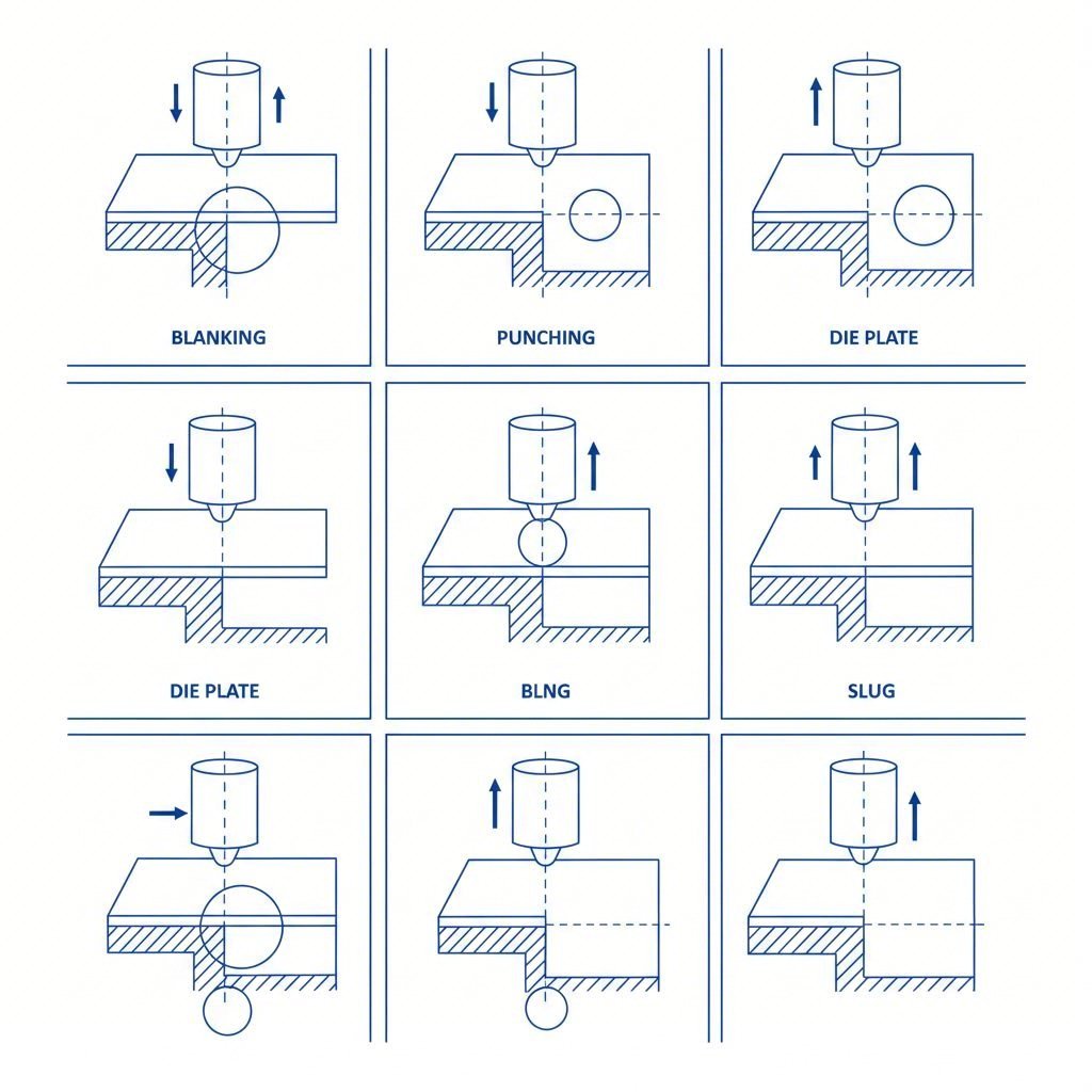
खाली करना यह असंख्य स्टैम्प किए गए भागों के लिए आरंभ बिंदु के रूप में कार्य करता है। इस संचालन के दौरान, एक पंच शीट धातु के माध्यम से बलपूर्वक प्रवेश करता है ताकि एक समतल आकृति — "ब्लैंक" — काटी जा सके, जो उसके बाद के संचालनों के लिए कार्य-टुकड़ा बन जाता है। ब्लैंकिंग स्टैम्पिंग धातु से मूल प्रोफाइल का निर्माण करती है, जिससे सब कुछ विकसित होता है। कटा हुआ टुकड़ा वांछित उत्पाद होता है, जबकि शेष शीट कचरा बन जाती है। ब्लैंकिंग कम-कार्बन इस्पात, एल्यूमीनियम और पीतल जैसी उन सामग्रियों के साथ सर्वोत्तम प्रदर्शन करती है जो साफ़-साफ़ काटी जा सकती हैं।
पंच करना यह ब्लैंकिंग के समान दिखता है, लेकिन इसका उद्देश्य विपरीत होता है। यहाँ, लक्ष्य कार्य-टुकड़े में छेद या कटआउट बनाना है — निकाला गया सामग्री कचरा होती है, और शेष शीट ही उत्पाद होती है। डाई स्टैम्पिंग संचालन में अक्सर पंचिंग को अन्य तकनीकों के साथ संयोजित किया जाता है ताकि माउंटिंग छेद, वेंटिलेशन स्लॉट या वजन कम करने की सुविधाएँ जोड़ी जा सकें। यह ठंडा-आकार देने वाली प्रक्रिया पतले एल्यूमीनियम से लेकर मोटी स्टील प्लेट तक की सामग्रियों को संभाल सकती है, हालाँकि छेद का आकार कार्य-टुकड़े की मोटाई के सापेक्ष किनारे की गुणवत्ता को प्रभावित करता है।
मोड़ना यह सपाट ब्लैंक्स को एक सीधी अक्ष के आसपास धातु को प्लास्टिक रूप से विकृत करके त्रि-आयामी भागों में परिवर्तित करता है। जब बल लगाया जाता है, तो धातु वक्र की बाहरी सतह पर खिंचती है और आंतरिक सतह पर संपीड़ित होती है। महत्वपूर्ण विचार क्या है? प्रत्येक धातु की एक न्यूनतम वक्र त्रिज्या होती है—इससे कम त्रिज्या पर वक्र बनाने पर दरारें उत्पन्न होती हैं। धातु के दाने की दिशा भी महत्वपूर्ण होती है; दाने की रेखाओं के लंबवत मोड़ने से कार्य टुकड़े के फटने का खतरा होता है। सफल मोड़ने की क्रियाएँ स्प्रिंगबैक को ध्यान में रखती हैं, जो एक प्रत्यास्थ पुनर्प्राप्ति है जिसके कारण निर्माण के बाद भाग आंशिक रूप से अपनी मूल स्थिति पर लौट जाते हैं।
सिक्का बनाना अत्यधिक दबाव लगाता है — जो अक्सर सामग्री के प्रवाह प्रतिबल को पार कर जाता है — ताकि सटीक सतह के विवरण और शुद्ध आयाम प्राप्त किए जा सकें। अन्य आकृति निर्माण प्रक्रियाओं के विपरीत, सिक्का निर्माण (कॉइनिंग) में स्टील और अन्य धातुओं को पूरी तरह से दबाव के अधीन किया जाता है, जिससे सामग्री पूर्णतः विकृत हो जाती है और प्रत्यास्थ प्रतिक्रिया (स्प्रिंगबैक) पूरी तरह समाप्त हो जाती है। यह तकनीक मुद्रा, पदक और सटीक यांत्रिक घटकों पर आपके द्वारा देखे जाने वाले तीव्र विवरणों का निर्माण करती है। क्या कोई समझौता है? उच्च औजार घिसावट और उल्लेखनीय प्रेस टनेज आवश्यकताओं के कारण बड़े भागों के लिए सिक्का निर्माण महंगा हो जाता है।
इम्बॉसिंग सामग्री को काटे बिना धातु की सतह पर उभरे हुए या धंसे हुए पैटर्न बनाता है। पुरुष और मादा डाई (साँचे) कार्य-टुकड़े को उनके बीच दबाकर धातु को सजावटी या कार्यात्मक राहत पैटर्न में खींचते हैं। आप घरेलू उपकरणों के पैनल, ऑटोमोटिव ट्रिम और पहचान प्लेटों पर उभरे हुए लक्षण देख सकते हैं। स्टैम्प और एम्बॉसर उन लचीली सामग्रियों के साथ सर्वोत्तम प्रदर्शन करते हैं जो फटे बिना खिंच सकती हैं — यहाँ एल्यूमीनियम और कम-कार्बन स्टील उत्कृष्ट प्रदर्शन करते हैं, जबकि उच्च-शक्ति वाले मिश्र धातुओं में एम्बॉसिंग के दौरान दरारें पड़ सकती हैं।
फ्लैंजिंग धातु के किनारों को विशिष्ट कोणों—आमतौर पर 90 डिग्री—पर मोड़कर मजबूती देने वाले होंठ, माउंटिंग सतहें या असेंबली सुविधाएँ बनाता है। पूर्ण बेंडिंग संचालनों के विपरीत, फ्लैंजिंग केवल कार्य-टुकड़े के किनारे के हिस्सों पर लागू होती है। दो प्रकार की फ्लैंजिंग मौजूद हैं: स्ट्रेच फ्लैंजिंग फ्लैंज को उत्तल रूप से मोड़ती है (बाहरी किनारा खिंचता है), जबकि श्रिंक फ्लैंजिंग अवतल वक्र बनाती है (आंतरिक किनारा संकुचित होता है)। सामग्री की तन्यता यह निर्धारित करती है कि झुर्रियाँ पड़ने या दरारें आने से पहले आप अपनी फ्लैंज ज्यामिति को कितनी अधिक चुनौतीपूर्ण बना सकते हैं।
खिंचाव फॉर्म डाई पर सामग्री को खींचकर धातु के सतह क्षेत्रफल का विस्तार करता है। यह तकनीक ऑटोमोटिव बॉडी पैनल और विमान के शेल (स्किन) जैसी चिकनी, वक्राकार सतहें बनाती है। खींचने के दौरान, धातु का फैलना होने के कारण उसकी मोटाई कम हो जाती है—डिज़ाइनरों को संरचनात्मक अखंडता बनाए रखने के लिए इस मोटाई कम होने को ध्यान में रखना आवश्यक है। एल्यूमीनियम मिश्र धातुओं और डीप-ड्रॉइंग स्टील ग्रेड जैसी अत्यधिक तन्य सामग्रियाँ सर्वोत्तम प्रदर्शन करती हैं, क्योंकि भंगुर धातुएँ अपेक्षित आकार प्राप्त करने से पहले ही टूट जाती हैं।
मोड़ना रोलिंग शीट मेटल के किनारों को वृत्ताकार प्रोफाइल में बदलती है, जिससे सुरक्षित किनारे, सजावटी विशेषताएँ या संरचनात्मक मजबूती प्राप्त होती है। उदाहरण के लिए, धातु के डिब्बे के रोल्ड रिम या कब्जे के बैरल के घुमाए गए किनारे के बारे में सोचें। कर्लिंग संचालन में सामग्री को क्रमिक रूप से कम त्रिज्या वाले वक्रों के माध्यम से मोड़ा जाता है, जब तक कि अभीष्ट कर्ल व्यास प्राप्त नहीं हो जाता। पतली गेज वाली सामग्री को कर्ल करना आसान होता है, जबकि मोटी सामग्री के लिए कई फॉर्मिंग चरणों या विशिष्ट टूलिंग की आवश्यकता होती है।
चित्रण समतल ब्लैंक्स को खोखले, त्रि-आयामी आकारों — कप, सिलेंडर, बॉक्स और जटिल आवरणों — में परिवर्तित करता है। पंच धातु को डाई के कोष्ठ में धकेलता है, जबकि ब्लैंक होल्डर का दबाव सामग्री के प्रवाह को नियंत्रित करता है। डीप ड्रॉइंग उन संचालनों को संदर्भित करती है जिनमें गहराई व्यास से अधिक होती है, जिसके लिए झुर्रियों या फटने को रोकने के लिए सामग्री के प्रवाह का सटीक नियंत्रण आवश्यक होता है। पीतल, तांबा, एल्यूमीनियम और विशिष्ट डीप-ड्रॉइंग स्टील सर्वोत्तम कार्य करते हैं, क्योंकि उनकी तन्यता उल्लेखनीय प्लास्टिक विकृति की अनुमति देती है।
भाग की आवश्यकताओं के अनुसार तकनीकों का चयन करना
सही स्टैम्पिंग ऑपरेशन का चयन आपके भाग की कार्यात्मक आवश्यकताओं को समझने से शुरू होता है। क्या आपको शीट स्टॉक से एक समतल प्रोफ़ाइल काटने की आवश्यकता है? ब्लैंकिंग इसे प्रदान करती है। फास्टनर्स के लिए माउंटिंग होल्स की आवश्यकता है? पंचिंग इसका संचालन करती है। मोड़े गए ज्यामिति से संरचनात्मक दृढ़ता की आवश्यकता है? बेंडिंग और फ्लैंजिंग संयुक्त रूप से मजबूत, हल्के भार वाले आकार बनाते हैं।
निम्नलिखित तालिका में सभी नौ तकनीकों को संकलित किया गया है, जो आपको अपनी विशिष्ट अनुप्रयोग आवश्यकताओं के अनुसार ऑपरेशनों का चयन करने में सहायता प्रदान करती है:
| तकनीक का नाम | प्राथमिक कार्य | विशिष्ट अनुप्रयोग | सामग्री के बारे में विचार |
|---|---|---|---|
| खाली करना | शीट धातु से समतल आकृतियों का कटाव | धातु शीट कटिंग, गैस्केट्स, वॉशर्स, आधार घटक | साफ-काटने वाली धातुओं को वरीयता दें; अत्यंत कठोर या भंगुर मिश्र धातुओं से बचें |
| पंच करना | कार्य-टुकड़ों में छेद या कटआउट बनाना | माउंटिंग होल्स, वेंटिलेशन स्लॉट्स, वजन कम करने के लिए विशेषताएँ | छेद-से-मोटाई अनुपात किनारे की गुणवत्ता को प्रभावित करता है; पायलट होल्स आम हैं |
| मोड़ना | सीधी अक्ष के अनुदिश कोणीय विरूपण | ब्रैकेट्स, एनक्लोज़र्स, फ्रेम्स, चैसिस घटक | न्यूनतम वक्रता त्रिज्या सामग्री के आधार पर भिन्न होती है; दाने की दिशा महत्वपूर्ण है |
| सिक्का बनाना | उच्च दबाव वाली सतह की विस्तृत जानकारी और सटीक आकार निर्माण | सिक्के, पदक, आभूषण, लोगो के साथ सटीक हार्डवेयर | उच्च टनेज की आवश्यकता होती है; स्प्रिंगबैक को समाप्त करने के लिए उत्कृष्ट |
| इम्बॉसिंग | उभरी हुई या धंसी हुई सतह के पैटर्न का निर्माण | सजावटी पैनल, नामपट्टिका, घरेलू उपकरणों की सतहें | लचीली सामग्री आवश्यक है; खिंचाव सीमा पैटर्न की गहराई को निर्धारित करती है |
| फ्लैंजिंग | विशिष्ट कोणों पर मोड़े गए किनारों का निर्माण | कंटेनर, पाइप, ऑटोमोटिव बॉडी प्रबलन | खिंचाव बनाम सिकुड़न फ्लैंजिंग के लिए अलग-अलग लचीलापन स्तर की आवश्यकता होती है |
| खिंचाव | फॉर्म डाईज़ पर सतह के क्षेत्रफल का विस्तार | ऑटोमोटिव दरवाज़े, छतें, विमानों के शरीर के आवरण | आकृति निर्माण के दौरान सामग्री पतली हो जाती है; उच्च तन्यता आवश्यक है |
| मोड़ना | किनारों को वृत्ताकार प्रोफाइल में रोल करना | कैन के किनारे, कब्ज़े के बैरल, सजावटी किनारे, सुरक्षा किनारे | पतले गेज वाले भाग आसानी से कर्ल होते हैं; मोटे स्टॉक के लिए क्रमिक चरणों की आवश्यकता होती है |
| चित्रण | समतल ब्लैंक्स से गहरी खोखली कोष्ठों का निर्माण | कप, सिलेंडर, आवरण, रसोई के सिंक | गहरी ड्रॉइंग के लिए विशेष ग्रेड की सामग्री आवश्यक है; ब्लैंक होल्डर दाब महत्वपूर्ण है |
व्यवहार में, अधिकांश स्टैम्प्ड भागों को एकल डाई में कई तकनीकों के संयोजन से निर्मित किया जाता है। एक प्रग्रेसिव डाई पायलट छेद कर सकती है, परिधि को ब्लैंक कर सकती है, माउंटिंग टैब्स को मोड़ सकती है, और भाग संख्या को एम्बॉस कर सकती है — यह सभी एक निरंतर संचालन में। प्रत्येक तकनीक की क्षमताओं और सीमाओं को समझना आपको ऐसे भागों के डिज़ाइन करने में सक्षम बनाता है जो कार्यात्मक आवश्यकताओं को पूरा करते हुए दक्षतापूर्ण रूप से निर्मित किए जा सकें।
इन मूलभूत कार्यों को स्पष्ट कर लेने के बाद, आप विभिन्न स्टैम्पिंग विधियों — प्रोग्रेसिव डाई, ट्रांसफर डाई, फ़ोरस्लाइड और फाइन ब्लैंकिंग — के बारे में अध्ययन करने के लिए तैयार हैं, जो इन तकनीकों को पूर्ण उत्पादन प्रणालियों में व्यवस्थित करती हैं।
प्रोग्रेसिव डाई बनाम ट्रांसफर डाई बनाम फ़ोरस्लाइड स्टैम्पिंग विधियाँ
आपने व्यक्तिगत तकनीकों — ब्लैंकिंग, बेंडिंग, ड्रॉइंग और अन्य — को आत्मसात कर लिया है। लेकिन यहाँ बातें रोचक हो जाती हैं: निर्माता इन कार्यों को कुशल उत्पादन प्रणालियों में कैसे व्यवस्थित करते हैं? इसका उत्तर आपकी विशिष्ट परियोजना के लिए सही स्टैम्पिंग विधि का चयन करने में निहित है। यदि आप इस निर्णय में गलती करते हैं, तो आप अनावश्यक क्षमताओं पर अत्यधिक व्यय कर सकते हैं या फिर उस प्रक्रिया के साथ संघर्ष कर सकते हैं जो आपकी आवश्यकताओं को पूरा नहीं कर पाएगी।
आधुनिक स्टैम्पिंग मशीनों और उत्पादन फर्शों पर चार विशिष्ट दृष्टिकोण प्रभुत्व स्थापित करते हैं। प्रत्येक के अपने विशिष्ट लाभ, सीमाएँ और लागत प्रोफ़ाइल होते हैं। आइए इन्हें विस्तार से समझें ताकि आप अपनी परियोजना की आवश्यकताओं को इष्टतम विधि के साथ सुमेलित कर सकें।
प्रोग्रेसिव डाई बनाम ट्रांसफर डाई – अपनी उत्पादन विधि का चयन करना
प्रोग्रेसिव डाई stamping यह उच्च मात्रा वाले उत्पादन का कार्यशील घोड़ा है। कल्पना कीजिए कि धातु की एक निरंतर पट्टी श्रृंखला में स्थित स्टेशनों के माध्यम से आगे बढ़ रही है—प्रत्येक स्टेशन पट्टी के आगे बढ़ने के साथ ही एक अलग-अलग कार्य करता है। पहले स्टेशन में छिद्रित किए गए पायलट छिद्र सामग्री को पियर्सिंग, फॉर्मिंग, बेंडिंग और अंतिम कट-ऑफ चरणों के माध्यम से आगे बढ़ते समय सभी को संरेखित रखते हैं। तैयार भाग अंत में गिर जाता है, जबकि अगला भाग ऊपर की ओर निर्माण जारी रखता है।
प्रोग्रेसिव डाई और स्टैम्पिंग को इतना शक्तिशाली क्या बनाता है? गति और दक्षता। धातु स्टैम्पिंग प्रेस के एकल स्ट्रोक से प्रत्येक स्टेशन पर एक साथ कार्य किया जाता है। जबकि पाँचवाँ स्टेशन एक पूर्ण भाग को काट रहा होता है, चौथा स्टेशन अंतिम बेंड पूरा कर रहा होता है, तीसरा स्टेशन छिद्र जोड़ रहा होता है, और पहला तथा दूसरा स्टेशन अगले भागों की तैयारी कर रहे होते हैं। उच्च-गति स्टैम्पिंग प्रेस पर उत्पादन दर 1,500 भाग प्रति मिनट से अधिक हो सकती है, जिससे यह विधि विशाल मात्रा में आवश्यक छोटे से मध्यम आकार के घटकों के लिए आदर्श हो जाती है।
क्या कुर्बानी देनी पड़ती है? धीरे-धीरे काम करने वाले डाई (प्रोग्रेसिव डाई) के लिए जटिल टूलिंग में महत्वपूर्ण प्रारंभिक निवेश की आवश्यकता होती है। इसके अतिरिक्त, ये भाग के ज्यामितीय आकार को सीमित करते हैं — घटकों को पूरे प्रसंस्करण के दौरान कैरियर स्ट्रिप से जुड़े रहना आवश्यक है, जिससे त्रि-आयामी जटिलता पर प्रतिबंध लग जाता है। गहरी ड्रॉ (डीप ड्रॉ) वाले भाग या जिन विशेषताओं को मध्य-प्रक्रिया में पुनर्स्थापित करने की आवश्यकता होती है, वे प्रोग्रेसिव डाई की क्षमताओं से परे चले जाते हैं।
ट्रांसफर डाइ स्टैम्पिंग इस प्रकार ज्यामितीय सीमाओं को हल किया जाता है कि भागों को स्टेशनों के बीच भौतिक रूप से अलग-अलग स्थानांतरित किया जाता है। कैरियर स्ट्रिप से जुड़े रहने के बजाय, खाली प्लेटों (ब्लैंक्स) को यांत्रिक उंगलियों या स्थानांतरण तंत्रों द्वारा उठाया जाता है और प्रत्येक संचालन के लिए पुनर्स्थापित किया जाता है। यह स्वतंत्रता बहुकोणीय संचालन की अनुमति देती है तथा प्रोग्रेसिव प्रणालियों में असंभव जटिल त्रि-आयामी आकृति निर्माण को संभव बनाती है।
ट्रांसफर स्टैम्पिंग कब अपनी प्रभावशीलता दिखाती है? वे बड़े भाग जो स्ट्रिप पर कुशलतापूर्ण रूप से फिट नहीं होते, वे घटक जिन पर विभिन्न दिशाओं से संचालन की आवश्यकता होती है, और वे ज्यामितियाँ जिनमें स्टेशनों के बीच महत्वपूर्ण पुनर्स्थापना की आवश्यकता होती है — ये सभी ट्रांसफर विधियों को पसंद करते हैं। ऑटोमोटिव संरचनात्मक घटकों और उपकरणों के आवरण अक्सर ट्रांसफर डाई उत्पादन का उपयोग करते हैं। प्रत्येक स्टैम्पिंग मशीन स्टेशन भाग तक इष्टतम कोणों से पहुँच प्रदान कर सकता है, जिससे गहरे ड्रॉ और अधिक जटिल फॉर्मिंग क्रम संभव होते हैं।
इसका नुकसान क्या है? प्रोग्रेसिव स्टैम्पिंग की तुलना में चक्र समय धीमा होता है, क्योंकि यांत्रिक ट्रांसफर को स्ट्रोक के बीच समय लगता है। टूलिंग लागत अभी भी उच्च रहती है, और ट्रांसफर तंत्र जटिलता जोड़ते हैं, जिसके लिए कुशल सेटअप और रखरखाव की आवश्यकता होती है।
फोरस्लाइड और मल्टीस्लाइड स्टैम्पिंग एकदम अलग दृष्टिकोण अपनाता है। ऊर्ध्वाधर प्रेस गति के बजाय, चार (या अधिक) उपकरण-वाहक स्लाइड्स कार्य-टुकड़े की ओर क्षैतिज दिशा में एकाधिक दिशाओं से आते हैं। तार या पट्टी का कच्चा माल मशीन में प्रवेश करता है, और आकृति निर्माण के उपकरण एक साथ सभी दिशाओं से इस सामग्री को आकार देते हैं।
यह विधि जटिल वक्रों, क्लिप्स, स्प्रिंग्स और जटिल तार आकृतियों के उत्पादन में उत्कृष्टता प्रदर्शित करती है, जिन्हें पारंपरिक स्टैम्पिंग मशीनों में कई संचालनों की आवश्यकता होती है। इलेक्ट्रॉनिक कनेक्टर्स, स्प्रिंग क्लिप्स और कई समतलों में वक्रों वाले छोटे ब्रैकेट्स फोरस्लाइड की विशेषज्ञता हैं। चूँकि उपकरण कई दिशाओं से एक साथ आते हैं, इसलिए रिटर्न्स, हुक्स और जटिल वक्र अनुक्रम वाले भागों का दक्षतापूर्ण निर्माण किया जा सकता है।
फोरस्लाइड टूलिंग की लागत प्रग्रेसिव या ट्रांसफर डाई की तुलना में काफी कम होती है — अक्सर समकक्ष भागों के लिए 50–70% कम। सेटअप की लचीलापन भाग संख्याओं के बीच त्वरित परिवर्तन की अनुमति देता है। हालाँकि, फोरस्लाइड छोटे भागों और हल्के-गेज सामग्रियों के साथ सबसे अच्छा काम करता है। भारी फॉर्मिंग ऑपरेशन, जिन्हें उच्च टनेज की आवश्यकता होती है, इसकी क्षमताओं से परे होते हैं।
जब फाइन ब्लैंकिंग प्रीमियम निवेश का औचित्य सिद्ध करती है
फाइन ब्लैंकिंग यह पारंपरिक स्टैम्पिंग की एक मौलिक सीमा — किनारे की गुणवत्ता — को संबोधित करता है। मानक ब्लैंकिंग में कतरनी क्षेत्र, ब्रेकआउट और बर्स के साथ किनारे उत्पन्न होते हैं, जिन्हें द्वितीयक फिनिशिंग की आवश्यकता होती है। फाइन ब्लैंकिंग त्रिगुण-क्रिया बल के प्रयोग द्वारा इन समस्याओं को समाप्त कर देती है — एक V-रिंग कट की परिधि के चारों ओर सामग्री पर दबाव डालती है, जबकि नीचे से प्रतिदबाव ब्लैंक को कतरन के दौरान समर्थन प्रदान करता है। परिणाम? पूर्णतः कतरित, चिकने किनारे, जिनकी आयामी सहिष्णुता मिलीमीटर के सौवें हिस्से में मापी जाती है।
सटीक छापन के लिए फाइन ब्लैंकिंग का उपयोग करने से भागों का उत्पादन होता है जो डी-बरिंग, ग्राइंडिंग या मशीनिंग के बिना ही असेंबली के लिए तैयार होते हैं। गियर दांत, कैम प्रोफाइल और सुरक्षा-महत्वपूर्ण घटकों को साफ किनारों और कड़ी सहिष्णुता से लाभ मिलता है। ऑटोमोटिव सीट तंत्र, लॉक घटक और पावर टूल गियर्स में अक्सर तब फाइन ब्लैंकिंग की आवश्यकता होती है जब सटीकता और किनारे की गुणवत्ता महत्वपूर्ण होती है।
उच्च निवेश लागत विशिष्ट उपकरण और टूलिंग की आवश्यकता को दर्शाती है। फाइन ब्लैंकिंग प्रेस सामान्य स्टैम्पिंग मशीनों की तुलना में धीमी गति से काम करती हैं, और ट्रिपल-एक्शन तंत्र के लिए सटीक सेटअप की आवश्यकता होती है। प्रति भाग लागत मानक ब्लैंकिंग की तुलना में अधिक होती है। लेकिन जब आप उन अतिरिक्त संचालनों को दूर करने और कार्यात्मक प्रदर्शन में सुधार को ध्यान में रखते हैं, तो फाइन ब्लैंकिंग अक्सर सटीक अनुप्रयोगों के लिए कुल लागत को कम करने में सक्षम होती है।
अभी भी अनिश्चित हैं कि आपकी परियोजना के लिए कौन सी विधि उपयुक्त है? निम्नलिखित तुलना में प्रमुख निर्णय कारकों को विस्तार से समझाया गया है:
| स्टैम्पिंग विधि | के लिए सबसे अच्छा | आयतन की सीमा | सहिष्णुता स्तर | खंड जटिलता | सापेक्ष लागत |
|---|---|---|---|---|---|
| प्रगतिशील डाइ | छोटे से मध्यम आकार के भाग, उच्च मात्रा में | वार्षिक 1,00,000 से लाखों तक | आमतौर पर ±0.05 से ±0.1 मिमी | मध्यम – कैरियर स्ट्रिप अटैचमेंट द्वारा सीमित | उच्च टूलिंग; उच्च मात्रा में प्रति भाग लागत कम |
| ट्रांसफर डाई | बड़े या ज्यामितीय रूप से जटिल भाग | वार्षिक 10,000 से 500,000 | आमतौर पर ±0.05 से ±0.15 मिमी | उच्च – पुनः स्थापित करने की क्षमता जटिल ज्यामिति को सक्षम बनाती है | उच्च टूलिंग; मध्यम प्रति भाग लागत |
| फोरस्लाइड/मल्टीस्लाइड | जटिल बेंड, क्लिप, स्प्रिंग, वायर फॉर्म | वार्षिक 5,000 से लाखों तक | आमतौर पर ±0.1 से ±0.25 मिमी | मोड़ों के लिए उच्च; भारी आकृति निर्माण के लिए सीमित | निम्न-से-मध्यम टूलिंग; प्रति-भाग प्रतिस्पर्धी |
| फाइन ब्लैंकिंग | साफ किनारों की आवश्यकता वाले उच्च-परिशुद्धता भाग | वार्षिक 10,000 से 500,000 | ±0.01 से ±0.05 मिमी तक प्राप्त किया जा सकता है | मध्यम — किनारे-केंद्रित अनुप्रयोगों के लिए | उच्च-गुणवत्ता वाली टूलिंग और प्रति-भाग लागत; द्वितीयक संचालन की लागत को कम करता है |
आपका चयन कई कारकों के संतुलन पर निर्भर करता है: वार्षिक मात्रा आवश्यकताएँ, ज्यामितीय जटिलता, आयामी परिशुद्धता की आवश्यकताएँ, और द्वितीयक संचालन सहित कुल लागत। मध्यम जटिलता वाले छोटे भागों का उच्च-मात्रा उत्पादन? प्रोग्रेसिव डाई प्रति-टुकड़ा न्यूनतम लागत प्रदान करती है। जटिल त्रि-आयामी ज्यामिति वाले बड़े संरचनात्मक घटक? ट्रांसफर डाई वह कार्य कर सकती है जो प्रोग्रेसिव डाई नहीं कर सकती। प्रतिस्पर्धी टूलिंग लागत पर जटिल मोड़ वाले आकार? फोरस्लाइड लचीलापन प्रदान करता है। अतिरिक्त परिष्करण संचालन के बिना उच्च-परिशुद्धता किनारे? फाइन ब्लैंकिंग अपनी उच्च लागत को औचित्यपूर्ण ठहराती है।
जब आपकी स्टैम्पिंग विधि का चयन कर लिया गया है, तो अगला महत्वपूर्ण निर्णय प्रतीक्षा कर रहा है: आपके अनुप्रयोग की आवश्यकताओं के अनुसार प्रदर्शन प्रदान करने के लिए कौन-सी धातु का उपयोग किया जाए? धातु के चयन से सीधे फॉर्मेबिलिटी से लेकर अंतिम भाग की टिकाऊपन तक सभी को प्रभावित किया जाता है — और यही वह विषय है जिसकी हम अगले चरण में जाँच करेंगे।
स्टैम्पिंग सफलता के लिए धातु चयन मार्गदर्शिका
आपने अपनी स्टैम्पिंग विधि — प्रोग्रेसिव, ट्रांसफर, फोरस्लाइड या फाइन ब्लैंकिंग — का चयन कर लिया है। लेकिन यहाँ वह प्रश्न है जो आपकी परियोजना को सफल या विफल बना सकता है: आप उस डाई के माध्यम से कौन-सी धातु का उपयोग करेंगे? गलत धातु का चयन करने पर आप दरारों, अत्यधिक स्प्रिंगबैक या उपकरणों के जल्दी क्षरण के साथ संघर्ष करने के लिए बाध्य होंगे। सही धातु का चयन करने पर भाग स्वच्छ रूप से बनते हैं, उत्पादन प्रक्रिया सुचारू रूप से चलती है और अंतिम घटकों का प्रदर्शन ठीक उसी प्रकार होता है जैसा कि डिज़ाइन के अनुसार आवश्यक था।
सामग्री का चयन अनुमान नहीं है। यह आपके भाग की कार्यात्मक आवश्यकताओं, निर्माण की जटिलता और उत्पादन अर्थव्यवस्था के आधार पर एक गणना-आधारित निर्णय है। आइए आधुनिक विनिर्माण में प्रभुत्व वाली स्टैम्पिंग के लिए धातु विकल्पों का पता लगाएँ — और उन गुणों को समझें जो उनकी स्टैम्पेबिलिटी (छापने योग्यता) निर्धारित करते हैं।
स्टील, एल्यूमीनियम, या ताँबा — अपने स्टैम्पिंग प्रोजेक्ट के लिए सही धातु का चयन
कार्बन स्टील स्टील अभी भी स्टैम्पिंग की धातु सामग्रियों का काम करने वाला धातु है। किफायती, व्यापक रूप से उपलब्ध और आकार देने में आसान, कार्बन स्टील ऑटोमोटिव ब्रैकेट्स से लेकर उपकरण हाउसिंग तक के सभी के लिए उपयुक्त है। विभिन्न कार्बन स्तर अलग-अलग ग्रेड बनाते हैं:
- कम-कार्बन स्टील (0.05–0.25% कार्बन): उत्कृष्ट आकार देने योग्यता और तन्यता के कारण यह गहरी ड्रॉइंग और जटिल मोड़ों के लिए सबसे अच्छा विकल्प है। कम-कार्बन ग्रेड से स्टैम्प किए गए स्टील के भाग दरार के बिना बनते हैं और कड़ी सहिष्णुता (टॉलरेंस) को बनाए रखते हैं।
- मध्यम-कार्बन स्टील (0.25–0.60% कार्बन): यह ताकत और उचित रूप से आकार देने की क्षमता के बीच संतुलन बनाए रखता है। यह कम-कार्बन विकल्पों की तुलना में अधिक भार क्षमता की आवश्यकता वाले संरचनात्मक घटकों के लिए उपयुक्त है।
- उच्च-शक्ति वाला कम-मिश्र धातु (HSLA) इस्पात: यह ऑटोमोटिव और संरचनात्मक अनुप्रयोगों के लिए श्रेष्ठ ताकत-से-वजन अनुपात प्रदान करता है, जहाँ सामग्री की मोटाई को कम करने से वजन कम होता है, बिना प्रदर्शन को कम किए बिना।
लेपित और गैल्वेनाइज़्ड स्टील यह कच्चे माल में निर्मित संक्षारण की चिंताओं को दूर करता है। हॉट-डिप गैल्वेनाइज़िंग, इलेक्ट्रोगैल्वेनाइज़िंग और विशिष्ट लेपन प्रक्रियाएँ स्टैम्पिंग के बाद के फिनिशिंग संचालन के बिना सुरक्षा प्रदान करती हैं। डाई क्लीयरेंस की गणना करते समय लेपन की मोटाई को ध्यान में रखें — जिंक परत फॉर्मिंग के दौरान सामग्री के व्यवहार को प्रभावित करती है।
स्टेनलेस स्टील यह संक्षारण प्रतिरोध को शानदार ताकत के साथ जोड़ता है, जिससे यह चिकित्सा उपकरणों, खाद्य प्रसंस्करण उपकरणों और समुद्री अनुप्रयोगों के लिए आवश्यक हो जाता है। हालाँकि, स्टेनलेस स्टील की स्टैम्पिंग के लिए इसके विशिष्ट गुणों का सम्मान करना आवश्यक है:
- 300 श्रृंखला (ऑस्टेनिटिक): प्रकार 301, 302 और 305 उत्कृष्ट संक्षारण प्रतिरोध और अच्छी आकृति देने की क्षमता प्रदान करते हैं। कार्य-कठोरीकरण तीव्र गति से होता है — जैसे-जैसे आप सामग्री को आकार देते हैं, वह कठोर और भंगुर होती जाती है, जिससे सावधानीपूर्ण प्रक्रिया योजना आवश्यक हो जाती है।
- 400 श्रृंखला (फेरिटिक और मार्टेन्सिटिक): ग्रेड 410, 420 और 440A चुंबकीय गुणों और उच्च ताकत प्रदान करते हैं, लेकिन ऑस्टेनिटिक ग्रेड की तुलना में इनकी तन्यता कम होती है।
- अवक्षेपण-कठोरीकरण ग्रेड: 17-4PH और 17-7PH ऊष्मा उपचार के बाद असाधारण ताकत प्राप्त करते हैं, हालाँकि इनके आकार देने में अधिक चुनौतियाँ उत्पन्न होती हैं।
ऑस्टेनिटिक स्टेनलेस स्टील के साथ एक महत्वपूर्ण विचार: अस्थायी संरचना विरूपण के दौरान रूपांतरित हो जाती है, जिससे मार्टेन्सिटिक चरण उत्पन्न होता है। उल्ब्रिच के सटीक स्टैम्पिंग मार्गदर्शिका के अनुसार, यह मार्टेन्साइट भंगुर होता है और आसानी से फट सकता है। जैसे-जैसे विरूपण बढ़ता है, मार्टेन्सिटिक सामग्री और अवशिष्ट प्रतिबल दोनों में वृद्धि होती है — जिससे स्टेनलेस स्टील की सफल स्टैम्पिंग के लिए सावधानीपूर्ण प्रक्रिया नियंत्रण आवश्यक हो जाता है।
एल्यूमीनियम मिश्र धातु जहां वजन कम करना महत्वपूर्ण होता है, वहां हल्के वजन वाले प्रदर्शन की आपूर्ति करें। स्टैम्प किया गया एल्युमीनियम लगभग समकक्ष स्टील के भागों के एक-तिहाई वजन का होता है, जिससे यह ऑटोमोटिव, एयरोस्पेस और उपभोक्ता इलेक्ट्रॉनिक्स अनुप्रयोगों के लिए अमूल्य हो जाता है। सामान्य एल्युमीनियम स्टैम्पिंग ग्रेड्स में शामिल हैं:
- 1100 श्रृंखला: व्यावसायिक रूप से शुद्ध एल्युमीनियम, जिसमें अत्यधिक आकार देने योग्यता (फॉर्मेबिलिटी) और संक्षारण प्रतिरोधकता होती है — गहरी ड्रॉइंग और जटिल आकृतियों के लिए आदर्श।
- 3003 और 3004: मध्यम ताकत के साथ अच्छी कार्यक्षमता; बर्तनों, साइनबोर्ड और सामान्य स्टैम्पिंग अनुप्रयोगों के लिए लोकप्रिय।
- 5052 और 5083: उच्च ताकत वाले समुद्री-श्रेणी के मिश्र धातुएँ, जिनमें मांगपूर्ण वातावरणों के लिए उत्कृष्ट संक्षारण प्रतिरोधकता होती है।
- 6061:ऊष्मा-उपचारणीय मिश्र धातु, जो अच्छी ताकत और आकार देने योग्यता प्रदान करती है; आमतौर पर संरचनात्मक अनुप्रयोगों के लिए उपयोग की जाती है।
एल्युमीनियम की कोमलता स्टील की तुलना में औजारों के क्षरण को कम करती है, जिससे डाई का जीवनकाल बढ़ जाता है। हालाँकि, इसकी गैलिंग की प्रवृत्ति — यानी औजारों की सतहों से चिपकना — उचित स्नेहन और कभी-कभी विशेष डाई कोटिंग्स की आवश्यकता होती है।
तांबा और तांबा एलोइज विद्युत चालकता, तापीय स्थानांतरण या एंटीमाइक्रोबियल गुणों की आवश्यकता वाले अनुप्रयोगों में उत्कृष्ट प्रदर्शन करते हैं। तांबे के स्टैम्पिंग से कनेक्टर, टर्मिनल, हीट एक्सचेंजर और सजावटी हार्डवेयर बनाए जाते हैं:
- शुद्ध तांबा (C110): विद्युत अनुप्रयोगों के लिए अधिकतम चालकता; उत्कृष्ट तन्यता जटिल आकार देने की अनुमति देती है।
- पीतल (तांबा-जस्ता मिश्र धातुएँ): अच्छी आकृति देने की क्षमता को आकर्षक उपस्थिति और मध्यम चालकता के साथ जोड़ता है; सजावटी और विद्युत घटकों के लिए लोकप्रिय।
- फॉस्फरस ब्रोंज़: चालकता बनाए रखते हुए ताकत और स्प्रिंग गुणों को जोड़ता है; संपर्क स्प्रिंग और कनेक्टर के लिए आदर्श।
- बेरिलियम तांबा: उत्कृष्ट ताकत और चालकता वाली प्रीमियम मिश्र धातु; मांग वाले अनुप्रयोगों में स्प्रिंग और विद्युत संपर्कों के लिए उपयोग की जाती है।
विशेष सामग्री विशिष्ट आवश्यकताओं वाले विशेष अनुप्रयोगों के लिए सेवा प्रदान करते हैं। टाइटेनियम एयरोस्पेस और चिकित्सा प्रत्यारोपणों के लिए अद्वितीय शक्ति-से-भार अनुपात प्रदान करता है—हालाँकि इसका स्प्रिंगबैक व्यवहार और गॉलिंग प्रवृत्ति स्टैम्पिंग संचालन को चुनौती देती है। निकल मिश्र धातुएँ चरम तापमान और संक्षारक वातावरण को संभाल सकती हैं। चांदी और सोना जैसी मूल्यवान धातुएँ इलेक्ट्रॉनिक्स और आभूषण निर्माण में प्रयुक्त होती हैं।
आदर्श परिणामों के लिए सामग्री मोटाई दिशा-निर्देश
सामग्री की मोटाई सीधे प्रभावित करती है कि कौन-से संचालन संभव हैं और भाग कैसे कार्य करते हैं। बहुत पतली होने पर संरचनात्मक अखंडता प्रभावित होती है। बहुत मोटी होने पर आकृति निर्माण बल उपकरण की क्षमता से अधिक हो जाते हैं या सामग्री के फटने की सीमा को पार कर जाते हैं। संचालन के प्रकार के आधार पर सामान्य दिशा-निर्देश:
- ब्लैंकिंग और पंचिंग: छिद्र का व्यास सामान्यतः सामग्री की मोटाई के बराबर या उससे अधिक होना चाहिए, ताकि पंच के टूटने को रोका जा सके और साफ कट बनाया जा सके। मोटी सामग्रियों के लिए पंच और डाई के बीच बड़े स्पष्टीकरण (क्लियरेंस) की आवश्यकता होती है।
- मोड़ना: न्यूनतम वक्रता त्रिज्या आमतौर पर सामग्री की मोटाई के 0.5 से 2 गुना के बीच होती है, जो सामग्री की तन्यता और धातु के दाने की दिशा पर निर्भर करती है। अधिक तीव्र वक्र बाहरी सतह पर दरारें उत्पन्न करने का जोखिम रखते हैं।
- खिंचाव: ड्रॉइंग अनुपात (ब्लैंक व्यास से पंच व्यास) एकल संचालन में आप कितनी गहराई तक ड्रॉ कर सकते हैं, इसकी सीमा निर्धारित करता है। पतली गेज आमतौर पर मध्यवर्ती अनीलिंग के बिना अधिक गहरी ड्रॉइंग की अनुमति देती हैं।
- चिह्नित करना: पैटर्न की गहराई सामग्री की मोटाई और तन्यता पर निर्भर करती है — गहरी विशेषताओं के लिए फटने से बचने के लिए मोटी, अधिक आकार देने योग्य सामग्रियों की आवश्यकता होती है।
कोल्ड-रोल्ड सामग्रियाँ हॉट-रोल्ड विकल्पों की तुलना में अधिक कड़ी मोटाई सहिष्णुता प्रदान करती हैं। विनिर्माण विशेषज्ञों के अनुसार, कोल्ड-रोल्ड स्टील चिकनी परिष्कृत सतहें, सटीक किनारे, आयामी एकरूपता और अधिक ताकत प्रदान करती है — ये विशेषताएँ उन सटीक स्टैम्पिंग संचालनों के लिए आदर्श बनाती हैं जिनमें सुसंगत परिणामों की आवश्यकता होती है।
सामग्री के चयन से आपके शुद्ध लाभ पर क्या प्रभाव पड़ता है? कठोर सामग्रियाँ टूलिंग के क्षरण को तेज़ करती हैं, जिससे रखरखाव की आवृत्ति और डाई के प्रतिस्थापन की लागत में वृद्धि होती है। स्टेनलेस स्टील जैसी अत्यधिक कार्य-कठोरण सामग्रियों के लिए आकृति निर्माण के चरणों के बीच मध्यवर्ती ऐनीलिंग संचालन की आवश्यकता हो सकती है। जब सामग्री के गुणों के कारण दबाव चक्रों को धीमा करने या अतिरिक्त स्नेहन की आवश्यकता होती है, तो उत्पादन की गति कम हो जाती है। और अंतिम भाग का प्रदर्शन — ताकत, संक्षारण प्रतिरोधकता, चालकता, भार — सभी प्रारंभिक सामग्री चयन के निर्णय पर सीधे निर्भर करते हैं।
सही धातु का चयन करना केवल समीकरण का आधा हिस्सा है। आपके चुनी गई सामग्री को आकार देने वाला उपकरण भी उतना ही महत्वपूर्ण है — और यह हमें स्टैम्पिंग प्रेस के चयन की ओर ले जाता है, जहाँ यांत्रिक, हाइड्रोलिक और सर्वो प्रौद्योगिकियाँ प्रत्येक उत्पादन फर्श पर विशिष्ट लाभ प्रदान करती हैं।
स्टैम्पिंग प्रेस के प्रकार और उपकरण चयन
आपने अपनी धातु का चयन कर लिया है — अब आपको उसे आकार देने के लिए सही मशीन की आवश्यकता है। जिस धातु स्टैम्पिंग प्रेस का आप चयन करते हैं, वह सीधे उत्पादन की गति, भागों की गुणवत्ता, ऊर्जा लागत और दीर्घकालिक रखरखाव व्यय को प्रभावित करती है। अपने अनुप्रयोग के अनुरूप एक प्रेस का चयन करें, ताकि उत्पादन कुशलतापूर्ण रूप से निर्बाध रूप से चलता रहे। यदि उपकरण का चयन आपकी आवश्यकताओं के अनुरूप नहीं है, तो आप हर कदम पर सीमाओं से संघर्ष करेंगे।
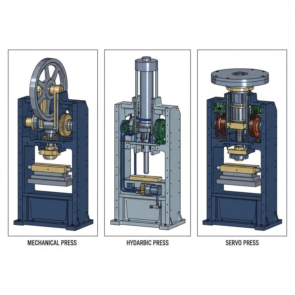
तीन प्रमुख प्रेस प्रौद्योगिकियाँ आधुनिक धातु स्टैम्पिंग मशीनों पर प्रभुत्व बनाए हुए हैं: यांत्रिक, हाइड्रोलिक और सर्वो-चालित प्रणालियाँ। प्रत्येक प्रणाली विशिष्ट अनुप्रयोगों के लिए विशिष्ट लाभ प्रदान करती है — इन अंतरों को समझना आपको अपनी उत्पादन आवश्यकताओं के अनुरूप प्रेस क्षमताओं का चयन करने में सहायता करता है।
यांत्रिक बनाम हाइड्रोलिक बनाम सर्वो प्रेस — एक तकनीकी तुलना
यांत्रिक प्रेस उच्च-मात्रा वाले उत्पादन के लिए अतुलनीय गति प्रदान करते हैं। एक विद्युत मोटर एक फ्लाईव्हील को घुमाती है, जो घूर्णन ऊर्जा को संग्रहीत करता है। जब क्लच सक्रिय होता है, तो यह ऊर्जा क्रैंकशाफ्ट के माध्यम से रैम के अवरोही स्ट्रोक को संचालित करने के लिए स्थानांतरित हो जाती है। परिणाम? शानदार गति पर सुसंगत और दोहराव योग्य गति।
यांत्रिक धातु स्टैम्पिंग प्रेस मशीनों को इतनी तेज़ क्यों बनाता है? फ्लाईव्हील लगातार घूमता रहता है और स्ट्रोक के बीच में ऊर्जा को संग्रहीत करता रहता है। मानक यांत्रिक प्रेस 10 से 18 स्ट्रोक प्रति मिनट की गति प्राप्त करती हैं, जबकि उच्च-गति वाले संस्करण छोटे भागों के उत्पादन के लिए प्रति मिनट 1,400 स्ट्रोक से अधिक प्राप्त करते हैं। यह गति लाभ इन प्रेसों को ब्लैंकिंग, पियर्सिंग और उथले फॉर्मिंग ऑपरेशन के लिए आदर्श बनाता है, जहाँ उत्पादन मात्रा सबसे अधिक महत्वपूर्ण होती है।
सीमा क्या है? बल की उपलब्धता स्ट्रोक की स्थिति पर निर्भर करती है। एक स्टील स्टैम्पिंग प्रेस केवल स्ट्रोक के निचले भाग के निकट एक विशिष्ट बिंदु पर अधिकतम टनेज प्रदान करती है। ऐसी कार्यवाहियाँ जिन्हें पूरे स्ट्रोक के दौरान पूर्ण बल की आवश्यकता होती है—जैसे गहरी ड्रॉइंग (डीप ड्रॉइंग)—यांत्रिक क्षमताओं से परे चली जाती हैं। इसके अतिरिक्त, निश्चित स्ट्रोक लंबाई भागों की ऊँचाई में काफी भिन्नता होने पर लचकशीलता को सीमित कर देती है।
हाइड्रॉलिक प्रेस नियंत्रण के लिए गति का त्याग करें। पंपों द्वारा दबावित हाइड्रॉलिक द्रव रैम को चालित करता है, जिससे स्ट्रोक के किसी भी बिंदु पर पूर्ण टनेज प्राप्त होता है—केवल निचले भाग पर नहीं। यह विशेषता हाइड्रॉलिक प्रणालियों को गहरी ड्रॉइंग के लिए प्राथमिक विकल्प बनाती है, जहाँ सामग्री को रूपांतरण क्रिया के समग्र दौरान स्थिर दबाव की आवश्यकता होती है।
बल नियंत्रण के अतिरिक्त, हाइड्रोलिक प्रेस में समायोज्य स्ट्रोक लंबाई और पूर्ण दबाव पर धीमा करने का समय (ड्वेल टाइम) उपलब्ध होता है। क्या आप चाहते हैं कि रैम स्थिति बनाए रखे जबकि सामग्री एक जटिल डाई कोष्ठ में प्रवाहित हो रही हो? हाइड्रोलिक प्रणालियाँ इसे आसानी से संभाल लेती हैं। विभिन्न डाई ऊँचाइयों या सामग्री की मोटाई के साथ काम कर रहे हैं? स्ट्रोक को यांत्रिक संशोधनों के बिना समायोजित करें।
इसका समझौता चक्र समय में दिखाई देता है। हाइड्रोलिक प्रेस आमतौर पर यांत्रिक विकल्पों की तुलना में धीमी गति से चलती हैं — और सरल कार्यों के लिए अक्सर काफी धीमी होती हैं। हालाँकि, जब बड़े या अनियमित आकार के भागों को बनाया जाता है, जिनमें सटीक बल नियंत्रण की आवश्यकता होती है, तो गुणवत्ता में सुधार गति के त्याग को औचित्यपूर्ण बना देता है।
सर्वो प्रेस ये स्टैम्पिंग मशीनरी में नवीनतम विकास का प्रतिनिधित्व करते हैं। फ्लाईव्हील या हाइड्रोलिक पंप के बजाय, सर्वो मोटर्स सीधे रैम को कार्यक्रमणीय गति प्रोफाइल के माध्यम से चलाती हैं। यह प्रौद्योगिकी यांत्रिक-जैसी गति को हाइड्रोलिक-जैसे नियंत्रण के साथ जोड़ती है — और ऐसी क्षमताएँ जोड़ती है जो कोई भी पारंपरिक प्रकार प्रदान नहीं कर सकता।
प्रोग्रामेबिलिटी का लाभ उत्पादन लचीलापन को बदल देता है। उद्योग विश्लेषण के अनुसार, सर्वो प्रेस उन्नत नियंत्रण की अनुमति देते हैं, जिसमें एक ही चक्र के भीतर विभिन्न स्ट्रोक गतियाँ, किसी भी बिंदु पर सटीक स्थिति निर्धारण और भाग संख्याओं के बीच त्वरित सेटअप समायोजन शामिल हैं। क्या आप स्ट्रोक के आकृति निर्माण (फॉर्मिंग) भाग के दौरान गति कम करना चाहते हैं, जबकि आगमन (एप्रोच) और वापसी (रिटर्न) के दौरान उच्च गति बनाए रखना चाहते हैं? सर्वो प्रौद्योगिकि यह संभव बनाती है।
ऊर्जा दक्षता सर्वो प्रेस का एक अतिरिक्त लाभ जोड़ती है। मोटर केवल तभी शक्ति आकर्षित करती है जब वह सक्रिय रूप से कार्य कर रही होती है—यह यांत्रिक प्रेसों के विपरीत है, जो लगातार फ्लाईव्हील को घुमाते रहते हैं, या हाइड्रोलिक प्रणालियों के विपरीत, जो लगातार पंप चलाती रहती हैं। ऐसे संचालनों के लिए, जहाँ स्ट्रोक के बीच महत्वपूर्ण निष्क्रिय समय होता है, ऊर्जा बचत काफी मात्रा में संचित हो जाती है।
प्रेस क्षमताओं का उत्पादन आवश्यकताओं के साथ मिलान
सही धातु स्टैम्पिंग मशीन का चयन करना आपकी विशिष्ट अनुप्रयोग आवश्यकताओं को समझने से शुरू होता है। इन महत्वपूर्ण कारकों पर विचार करें:
- टनेज आवश्यकताएँ: अपने फॉर्मिंग ऑपरेशन के लिए आवश्यक बल की गणना करें। छोटे आकार के प्रेस अतिभार के कारण क्षति के जोखिम में होते हैं; बड़े आकार के उपकरण पूंजी निवेश को व्यर्थ कर देते हैं।
- स्ट्रोक दर की आवश्यकता: सरल भागों के उच्च-मात्रा उत्पादन के लिए यांत्रिक गति अधिक उपयुक्त है। जटिल फॉर्मिंग ऑपरेशन के लिए, मात्रा के बावजूद, हाइड्रोलिक या सर्वो नियंत्रण का लाभ उठाया जाता है।
- भाग की ज्यामिति: गहरी ड्रॉ और जटिल आकृतियाँ, जिन्हें लगातार बल की आवश्यकता होती है, हाइड्रोलिक या सर्वो प्रणालियों की ओर इशारा करती हैं। उथले ब्लैंकिंग और पियर्सिंग ऑपरेशन के लिए यांत्रिक प्रेस उपयुक्त हैं।
- सामग्री की विशेषताएँ: स्टेनलेस स्टील या उच्च-शक्ति मिश्र धातु जैसी फॉर्म करने में कठिन सामग्री अक्सर फॉर्मिंग गति और बल प्रोफाइल को अनुकूलित करने के लिए सर्वो प्रोग्रामेबिलिटी से लाभान्वित होती हैं।
- उत्पादन लचीलापन: विविध भागों का उत्पादन करने वाले जॉब शॉप्स को सर्वो की त्वरित-परिवर्तन क्षमता से लाभ होता है। लाखों समान भागों का उत्पादन करने वाली समर्पित उत्पादन लाइनों को इस लचीलापन की आवश्यकता नहीं हो सकती है।
निम्नलिखित तुलना विभिन्न प्रेस प्रकारों के मुख्य अंतरों का सारांश प्रस्तुत करती है:
| प्रेस प्रकार | गति सीमा | बल नियंत्रण | ऊर्जा दक्षता | सर्वश्रेष्ठ उपयोग | प्रतिरक्षा की विवेचना |
|---|---|---|---|---|---|
| यांत्रिक | 10–1,400+ स्ट्रोक/मिनट | केवल स्ट्रोक के निचले भाग के निकट पूर्ण बल | मध्यम — फ्लाईव्हील लगातार चलता रहता है | ब्लैंकिंग, पियर्सिंग, उथला फॉर्मिंग, उच्च-मात्रा उत्पादन | क्लच और ब्रेक का क्षरण; फ्लाईव्हील बेयरिंग का रखरोट; निरंतर स्नेहन की आवश्यकता |
| हाइड्रोलिक | सामान्यतः 10–50 स्ट्रोक/मिनट | पूरे स्ट्रोक के दौरान पूर्ण टनेज उपलब्ध | निचला – पंप संचालन के दौरान चलते हैं | गहरा ड्रॉइंग, बड़े भागों का फॉर्मिंग, विश्राम समय की आवश्यकता वाले संचालन | हाइड्रोलिक द्रव की निगरानी और प्रतिस्थापन; सील की अखंडता; पंप रखरोट |
| सर्वो | परिवर्तनशील – अनुप्रयोग के अनुसार प्रोग्राम करने योग्य | पूर्णतः प्रोग्राम करने योग्य बल और स्थिति प्रोफाइल | उच्चतम – केवल मांग के अनुसार शक्ति | जटिल आकार निर्माण, विविध उत्पादन, परिशुद्धता अनुप्रयोग | सर्वो मोटर और ड्राइव इलेक्ट्रॉनिक्स; कम यांत्रिक घर्षण घटक |
अभी भी यह तय नहीं कर पाए हैं कि किस दिशा में जाना है? अपने सबसे चुनौतीपूर्ण अनुप्रयोग के आधार पर अपना निर्णय लें। वह धातु स्टैम्पिंग प्रेस मशीन जो आपके सबसे कठिन कार्य को सँभालती है, आसान कार्यों को तो और भी आसानी से पूरा कर लेगी। लेकिन यदि कोई प्रेस आसान भागों के लिए चुनी गई है, तो जटिलता बढ़ने पर वह काम करने में कठिनाई का सामना कर सकती है।
प्रेस के प्रकार को समझ लेने के बाद, एक अन्य महत्वपूर्ण पहलू आपके ध्यान की प्रतीक्षा कर रहा है: जब भाग सही तरीके से नहीं निकलते हैं, तो क्या होता है? अच्छी तरह से डिज़ाइन की गई स्टैम्पिंग ऑपरेशन में भी दोष उत्पन्न हो सकते हैं—और उनके निदान तथा उन्मूलन के तरीके जानना, असफल उत्पादन लाइनों को विश्व-स्तरीय विनिर्माण से अलग करता है। आइए उन ट्रबलशूटिंग रणनीतियों का पता लगाएँ जो गुणवत्ता को लक्ष्य पर बनाए रखती हैं।
दोषों का निवारण और गुणवत्ता नियंत्रण मानक
यहाँ तक कि सबसे सावधानीपूर्ण ढंग से डिज़ाइन किए गए धातु स्टैम्पिंग प्रक्रियाओं में भी समस्याएँ उत्पन्न होती हैं। भाग खराब किनारों, अप्रत्याशित वक्रों या लक्ष्य से विचलित आयामों के साथ निकलते हैं। जब दोष प्रकट होते हैं, तो यह जानना कि ठीक क्या गलत हुआ — और इसे कैसे ठीक किया जाए — उत्पादक ऑपरेशन्स को महंगे कचरे के ढेर से अलग कर देता है।
वास्तविकता यह है कि अधिकांश स्टैम्पिंग दोष पूर्वानुमेय कारणों से उत्पन्न होते हैं। इन मूल कारणों को समझना प्रतिक्रियाशील संकट प्रबंधन को पूर्वानुमानात्मक रोकथाम में बदल देता है। आइए स्टैम्प किए गए धातु भागों को प्रभावित करने वाले छह सबसे सामान्य दोषों और उन्हें दूर करने के लिए सिद्ध समाधानों पर विचार करें।
सामान्य स्टैम्पिंग दोषों का निदान और उनका उन्मूलन
बर्र ये कट सतहों के साथ उठे हुए धातु के किनारों या तीव्र उभार के रूप में प्रकट होते हैं। ये अवांछित रूपांकन सुरक्षा के लिए खतरा पैदा करते हैं, असेंबली में बाधा डालते हैं और प्रक्रिया से संबंधित मूल समस्याओं का संकेत देते हैं।
- प्रमुख कारण: पंच और डाई के बीच अत्यधिक खाली स्थान के कारण सामग्री साफ़ काटने के बजाय प्रवाहित हो जाती है। घिसे हुए या चिपके हुए कटिंग एज़ भी इसी प्रभाव को उत्पन्न करते हैं। उद्योग अनुसंधान के अनुसार, 0.1 मिमी से अधिक बर्र ऊँचाई आमतौर पर खाली स्थान या घिसावट की समस्याओं को दर्शाती है, जिनका तुरंत ध्यान रखा जाना आवश्यक है।
- समाधान: डाई के खाली स्थान को सामग्री की मोटाई के 8–12% तक समायोजित करें — मृदु इस्पात के लिए छोटे मान का उपयोग करें और कठोर सामग्रियों के लिए बड़े मान का उपयोग करें। नियमित डाई निरीक्षण कार्यक्रम लागू करें, जिसमें प्रत्येक 50,000 स्ट्रोक के बाद कटिंग एज़ की जाँच की जाए। लगातार समस्याओं के लिए, V-आकार के ब्लैंक होल्डर्स के साथ फाइन ब्लैंकिंग प्रौद्योगिकी पर विचार करें, जो बर्र-मुक्त किनारों का उत्पादन करती है।
झुर्रियाँ जब आकृति निर्माण के दौरान अतिरिक्त सामग्री तरंगित सतहें या एकत्रित किनारों के रूप में विकृत हो जाती है, तो ये बनते हैं, जिससे भाग की कार्यक्षमता और उपस्थिति प्रभावित होती है।
- प्रमुख कारण: अपर्याप्त ब्लैंक होल्डर दबाव के कारण सामग्री डाई के कोटरों में अनियंत्रित रूप से प्रवाहित हो जाती है। अनुचित स्नेहन असमान घर्षण क्षेत्रों का निर्माण करता है। आकर्षण अनुपात जो सामग्री की क्षमताओं से अधिक होते हैं, अतिरिक्त धातु को सीमित स्थानों में धकेल देते हैं।
- समाधान: सटीक समायोजन के लिए सर्वो-नियंत्रित हाइड्रोलिक पैड का उपयोग करके ब्लैंक होल्डर बल में वृद्धि करें। सामग्री प्रवाह को संतुलित करने के लिए ड्रॉइंग रिब लेआउट को अनुकूलित करें। गहरी ड्रॉइंग कार्यों के लिए, प्रारंभिक 60% ड्रॉ के साथ चरणबद्ध फॉर्मिंग को लागू करें, जिसके बाद द्वितीयक आकृति निर्माण कार्य किए जाते हैं।
स्प्रिंगबैक यह तब होता है जब स्टैम्प किए गए भाग फॉर्मिंग के बाद अपने मूल सपाट आकार की ओर आंशिक रूप से वापस लौटते हैं। यह प्रत्यास्थ पुनर्प्राप्ति बेंड कोणों को लक्ष्य से विचलित कर देती है और सटीक धातु स्टैम्पिंग भागों में आयामी विचलन का कारण बनती है।
- प्रमुख कारण: सभी धातुएँ प्लास्टिक विरूपण के बाद प्रत्यास्थ पुनर्प्राप्ति प्रदर्शित करती हैं — सामग्री फॉर्मिंग दबाव के छूटने पर "वापस झटका" देती है। उच्च-शक्ति इस्पात और एल्यूमीनियम मिश्र धातुएँ विशेष रूप से आक्रामक स्प्रिंगबैक व्यवहार प्रदर्शित करती हैं। फॉर्मिंग स्ट्रोक के दौरान अपर्याप्त ओवरबेंडिंग इस प्राकृतिक प्रवृत्ति की भरपाई करने में विफल रहती है।
- समाधान: सामग्री के व्यवहार के CAE सिमुलेशन के आधार पर स्प्रिंगबैक के मुआवजे के साथ डिज़ाइन डाई। कॉइनिंग संचालन सामग्री के प्रवाह प्रतिबल को पार करके स्प्रिंगबैक को पूरी तरह से समाप्त कर देते हैं। कड़ी कोणीय सहिष्णुता की आवश्यकता वाले स्टैम्प्ड स्टील भागों के लिए, 0.05–0.1 मिमी के मजबूत दबाव सुधार के साथ शेपिंग प्रक्रियाएँ जोड़ें।
टूटना सामग्री विफलता को दर्शाता है — जिससे भाग अउपयोगी हो जाते हैं, जैसे विभाजन या फ्रैक्चर। दरारें आमतौर पर बेंड त्रिज्या, ड्रॉ कॉर्नर या उच्च सामग्री प्रतिबल वाले क्षेत्रों में दिखाई देती हैं।
- प्रमुख कारण: रूपांतरण के दौरान सामग्री की तन्यता सीमा को पार करने से दरारें उत्पन्न होती हैं। सामग्री की मोटाई के लिए डाई त्रिज्या बहुत छोटी होने से तनाव इतना केंद्रित हो जाता है कि धातु उसे सहन नहीं कर पाती। पिछली संचालनों से ठंडा कार्य करने से शेष रूपांतरण क्षमता कम हो जाती है।
- समाधान: डाई के कोने की त्रिज्या को कम से कम चार गुना सामग्री की मोटाई तक बढ़ाएँ (R ≥ 4t)। उच्च-सामर्थ्य इस्पात के लिए, लचीलापन में सुधार के लिए 200–400°C पर गर्म आकृति निर्माण (हॉट फॉर्मिंग) कार्यान्वित करें। आकृति निर्माण के चरणों के बीच मध्यवर्ती अनीलिंग जोड़कर सामग्री की कार्ययोग्यता को पुनर्स्थापित करें। लंबाई में अधिक विस्तार (एलोंगेशन) के गुणों वाली सामग्री पर स्विच करने पर विचार करें।
सतह पर खरोंच क्षति भाग की उपस्थिति को प्रभावित कर सकती है और जब सुरक्षात्मक लेपों को भेदा जाता है, तो संक्षारण प्रतिरोध को भी कमजोर कर सकती है।
- प्रमुख कारण: खुरदुरी डाई सतहें आकृति निर्माण के दौरान दोषों को भागों पर स्थानांतरित कर देती हैं। सामग्री और टूलिंग के बीच फँसे विदेशी कण घर्षण चिह्न उत्पन्न करते हैं। अपर्याप्त या दूषित स्नेहन धातु-से-धातु संपर्क को रोकने में विफल रहता है।
- समाधान: डाई सतहों को Ra 0.2μm या उससे भी बेहतर (फाइनर) तक पॉलिश करें। सतह की टिकाऊपन में वृद्धि के लिए क्रोम प्लेटिंग या टीडी (TD) उपचार लागू करें। ऐसे वाष्पशील स्टैम्पिंग तेलों का उपयोग करें जो एस्टर-आधारित स्नेहक हों और जिन्हें आसानी से साफ़ किया जा सके। स्टैम्पिंग से पहले आने वाली सामग्रियों को पूर्व-सफाई के द्वारा गंदगी, धूल और सतही दूषण से मुक्त कर दें।
आयामिक भिन्नताएँ - जब भाग अनुमत सहिष्णुता विनिर्देशों के बाहर विचलित हो जाते हैं, तो असेंबली के फिट और कार्यात्मक प्रदर्शन को कमजोर कर देते हैं।
- प्रमुख कारण: डाई के पहने जाने से धीरे-धीरे कोष्ठ के आयाम बढ़ जाते हैं। आने वाले स्टॉक में सामग्री की मोटाई में भिन्नताएँ फॉर्मिंग ऑपरेशन के माध्यम से प्रसारित होती हैं। दबाव यंत्र की अपर्याप्त दृढ़ता या खराब स्लाइड समानांतरता भार के अधीन विक्षेप की अनुमति देती है। उत्पादन के दौरान तापमान में परिवर्तन टूलिंग के आयामों और सामग्री के व्यवहार दोनों को प्रभावित करते हैं।
- समाधान: डाइज़ में गाइड पोस्ट या सटीक स्थिति निर्धारण पिन जोड़ें। नियमित रूप से प्रेस की समानांतरता और टनेज डिलीवरी की जाँच करें। ±0.02 मिमी की मोटाई सहिष्णुता सत्यापन के साथ आने वाली सामग्री का निरीक्षण करें। अनुसार, गुणवत्ता नियंत्रण विशेषज्ञ , सटीक स्टैम्पिंग भागों के लिए आयामी सहिष्णुताएँ अक्सर ±0.05 मिमी के आसपास होती हैं — जो दो कागज़ की शीटों की मोटाई के बराबर है।
गुणवत्ता नियंत्रण उपाय जो प्रथम-पास मंजूरी सुनिश्चित करते हैं
उत्पादन के बाद दोषों का पता लगाना सामग्री, समय और धन का अपव्यय है। प्रभावी गुणवत्ता प्रणालियाँ समस्याओं का पता तभी लगाती हैं जब वे विकसित हो रही हों— या इससे भी बेहतर, उन्हें पूरी तरह से रोक देती हैं। एक संपूर्ण गुणवत्ता ढांचा बनाने के लिए तीन अंतर्संबद्ध दृष्टिकोणों का उपयोग किया जाता है:
प्रक्रिया-मध्य निरीक्षण (IPQC) उत्पादन की वास्तविक समय में निगरानी करता है। प्रथम लेख निरीक्षण बड़े पैमाने पर उत्पादन शुरू होने से पहले आकार, बाह्य रूप और कार्यक्षमता की पुष्टि करता है। गश्ती निरीक्षण नियमित अंतराल पर भागों के नमूने लेता है— प्रत्येक ३० मिनट में पाँच टुकड़ों की जाँच करने से प्रक्रिया में हो रहे विचलन को हज़ारों दोषों के जमा होने से पहले पकड़ा जा सकता है। ऑटोमोटिव सुरक्षा या चिकित्सा उपकरणों में उपयोग किए जाने वाले स्टैम्प किए गए भागों के लिए, ग्राहकों तक शून्य दोष पहुँचाने के सुनिश्चित करने के लिए १००% निरीक्षण आवश्यक हो सकता है।
सांख्यिकीय प्रक्रिया नियंत्रण (SPC) निरीक्षण डेटा को कार्यान्वयन योग्य बुद्धिमत्ता में परिवर्तित करता है। आयामी मापों के नियंत्रण आलेख उन प्रवृत्तियों को उजागर करते हैं जो तब तक दिखाई देती हैं जब तक कि सहनशीलता सीमाएँ लांघी नहीं जाती हैं। छिद्र के व्यास में धीमी वृद्धि गाइड पोस्ट के क्षरण को इंगित कर सकती है — इस प्रतिरूप को शुरुआत में पकड़ लेने से पूरे बैच के विनिर्देशों से बाहर होने से रोका जा सकता है। प्रक्रिया क्षमता सूचकांक (CPK) यह मापते हैं कि क्या आपकी प्रक्रिया आवश्यकताओं को लगातार पूरा करने में सक्षम है। CPK मान 1.33 से कम होने पर प्रक्रिया अस्थिर होती है और उसमें समायोजन की आवश्यकता होती है।
अंतिम प्रमाणीकरण यह शिपमेंट से पहले अंतिम गेट के रूप में कार्य करता है। AQL मानकों के अनुसार नमूना निरीक्षण — उदाहरण के लिए, 5,000 के बैच से 200 टुकड़ों का मापन — कुल बैच की गुणवत्ता की पुष्टि करता है। ग्राहकों द्वारा पहचाने गए महत्वपूर्ण आयामों का सख्त निरीक्षण किया जाता है, जिसमें अक्सर शिपमेंट के साथ दस्तावेज़ीकृत माप डेटा भी शामिल होता है। स्टेनलेस स्टील जैसी तनाव-संवेदनशील सामग्रियों के लिए, अवशिष्ट तनाव मुक्ति के कारण आयामी परिवर्तनों को पकड़ने के लिए 12–24 घंटे के स्थिरीकरण के बाद द्वितीयक निरीक्षण किया जाता है।
स्टैम्पिंग की विधियों के अनुसार सहनशीलता क्षमताएँ काफी हद तक भिन्न होती हैं। प्रोग्रेसिव और ट्रांसफर डाई संचालन आमतौर पर ±0.05 से ±0.15 मिमी की आयामी शुद्धता प्राप्त करते हैं। अत्यधिक सटीकता की आवश्यकता वाले अनुप्रयोगों के लिए फाइन ब्लैंकिंग ±0.01 से ±0.05 मिमी की सहनशीलता प्रदान करती है। इन क्षमताओं को समझना आपको डिज़ाइन के दौरान उचित सहनशीलता के निर्दिष्ट करने में सहायता करता है—जिससे आप उस सटीकता की मांग करने से बच सकते हैं, जिसे आपकी चुनी गई प्रक्रिया विश्वसनीय रूप से प्रदान नहीं कर सकती, और इस प्रकार अनावश्यक लागत से बचाव किया जा सकता है।
गुणवत्ता संबंधी समस्याएँ दुर्लभता से ही अपने आप में मौजूद होती हैं। बर्स (धार) का होना घिसावट का संकेत हो सकता है, जो अंततः आयामी विचलन का कारण बन सकती है। दरारें ऐसी तनाव स्थितियों को दर्शाती हैं जो और भी गंभीर हो सकती हैं। प्रभावी ट्रबलशूटिंग में व्यक्तिगत दोषों के पार जाकर व्यवस्थागत समस्याओं की पहचान करना शामिल है। जब समस्याएँ व्यक्तिगत सुधारों के बावजूद भी बनी रहती हैं, तो पूरी श्रृंखला की जाँच करें: आने वाली सामग्री की गुणवत्ता, डाई की स्थिति, प्रेस के पैरामीटर और ऑपरेटर की प्रक्रियाएँ—ये सभी अंतिम भाग की गुणवत्ता को प्रभावित करते हैं।
दोषों को समझ लेने और गुणवत्ता प्रणालियों की स्थापना के बाद, आप उन स्टैम्प किए गए भागों का उत्पादन करने के लिए तैयार हैं जो विनिर्देशों को लगातार पूरा करते हैं। लेकिन ये भाग वास्तव में कहाँ जाते हैं? इसका उत्तर लगभग हर उद्योग तक फैला हुआ है — और प्रत्येक उद्योग अपनी विशिष्ट आवश्यकताएँ लाता है, जो स्टैम्पिंग ऑपरेशन्स के प्रदर्शन को आकार देती हैं। आइए अब इन अनुप्रयोगों का अध्ययन करें।
ऑटोमोटिव से लेकर मेडिकल उपकरणों तक उद्योग अनुप्रयोग
स्टैम्प किए गए धातु घटक आपके चारों ओर रोज़ाना मौजूद होते हैं — बस आप उन्हें नोटिस नहीं करते। आपकी कार के इंजन को स्थिर रखने वाला ब्रैकेट, आपके स्मार्टफोन के सर्किट बोर्ड्स को जोड़ने वाला कनेक्टर, आपके पेसमेकर के इलेक्ट्रॉनिक्स की सुरक्षा के लिए उपयोग किया जाने वाला हाउसिंग। प्रत्येक अनुप्रयोग स्टैम्पिंग प्रक्रिया से कुछ अलग-अलग आवश्यकताएँ रखता है। इन उद्योग-विशिष्ट आवश्यकताओं को समझना आपको अपने विशिष्ट परियोजना के लिए सही प्रक्रिया, सामग्री और गुणवत्ता मानकों को निर्दिष्ट करने में सहायता प्रदान करता है।
ऑटोमोटिव स्टैम्पिंग — बॉडी पैनल्स से लेकर सुरक्षा घटकों तक
एक विशिष्ट वाहन में 300 से 500 स्टैम्प किए गए धातु घटक होते हैं। इंजन कवर के नीचे, आप बैटरी टर्मिनल, सेंसर माउंटिंग ब्रैकेट और ऊष्मा रोधक पाएंगे। केबिन के अंदर, सीट तंत्र और दरवाज़े के लॉच घटक होते हैं। संरचना भर में, शरीर पैनल और टक्कर अवशोषण भाग होते हैं। प्रत्येक घटक समतल धातु शीट से शुरू हुआ था।
ऑटोमोटिव धातु स्टैम्पिंग को कार्य और महत्वपूर्णता के आधार पर स्पष्ट श्रेणियों में विभाजित किया जाता है:
- बॉडी पैनल और क्लोजर: दरवाज़े, इंजन कवर, फेंडर और छत पैनलों के लिए बड़े पैमाने की ट्रांसफर डाई ऑपरेशन की आवश्यकता होती है, जिसमें पेंट चिपकने के लिए सटीक सतह गुणवत्ता आवश्यक होती है। ये उच्च मात्रा वाले धातु स्टैम्पिंग अनुप्रयोग लाखों भागों में अत्यधिक स्थिरता की मांग करते हैं।
- संरचनात्मक घटक: फ्लोर पैन, क्रॉस मेम्बर और क्रैश रेल्स में सुरक्षा विनियमों को पूरा करने के लिए उच्च-शक्ति वाले इस्पात का उपयोग किया जाता है। निलंबन और ड्राइवट्रेन प्रणालियों के साथ जुड़ने वाले घटकों के लिए टॉलरेंस काफी कड़े हो जाते हैं।
- ब्रैकेट और माउंटिंग हार्डवेयर: इंजन माउंट्स, ट्रांसमिशन ब्रैकेट्स और एग्जॉस्ट हैंगर्स को लगातार कंपन और तापीय चक्रों का सामना करना पड़ता है। सामग्री का चयन ताकत, संक्षारण प्रतिरोध और लागत के बीच संतुलन बनाए रखता है।
- सुरक्षा-महत्वपूर्ण भाग: सीट बेल्ट एंकर, एयरबैग हाउसिंग और ब्रेक घटकों के लिए ±0.002 इंच या उससे भी कड़े टॉलरेंस की आवश्यकता होती है — जिसमें शून्य दोष सहनशीलता होती है।
प्रमाणन परिदृश्य ऑटोमोटिव स्टैम्पिंग में सभी कुछ को आकार देता है। IATF 16949 प्रमुख ऑटोमेकर्स को आपूर्ति करने के लिए प्रमाणन अनिवार्य है। यह गुणवत्ता प्रबंधन मानक ISO 9001 पर आधारित है तथा दोष रोकथाम, विचरण कम करने और आपूर्ति श्रृंखला प्रबंधन के लिए विशिष्ट आवश्यकताएँ शामिल करता है। PPAP (उत्पादन भाग स्वीकृति प्रक्रिया) के दस्तावेज़ यह साबित करते हैं कि आपके भाग उत्पादन शुरू होने से पहले सभी इंजीनियरिंग आवश्यकताओं को पूरा करते हैं।
ऑटोमोटिव अनुप्रयोगों में मात्रा आवश्यकताएँ अक्सर वार्षिक रूप से लाखों या करोड़ों टुकड़ों तक पहुँच जाती हैं। छोटे घटकों के लिए प्रगतिशील डाई स्टैम्पिंग प्रमुखता से उपयोग की जाती है, जो जटिलता के आधार पर प्रति मिनट 20 से 200 भागों का उत्पादन करती है। उन निर्माताओं के लिए, जो इन मांगों वाले OEM मानकों को पूरा करने वाले सटीक स्टैम्पिंग डाई समाधानों की तलाश में हैं, IATF 16949 प्रमाणन और उन्नत CAE सिमुलेशन क्षमताओं वाले साझेदार — जैसे कि शाओयी का ऑटोमोटिव स्टैम्पिंग डाई विभाग — त्वरित प्रोटोटाइपिंग के माध्यम से केवल 5 दिनों में उत्पादन के समय-सीमा को तेज़ कर सकते हैं और 93% प्रथम-पास मंजूरी दर प्राप्त कर सकते हैं।
विद्युत वाहनों (EV) की ओर बदलाव ने हल्की सामग्रियों, वैद्युतचुंबकीय कवरेज (शील्डिंग), और तापीय प्रबंधन घटकों के लिए नई आवश्यकताएँ उत्पन्न कर दी हैं। EV उत्पादन के बढ़ते पैमाने के साथ स्टैम्प किए गए एल्युमीनियम बैटरी एन्क्लोज़र और कॉपर बस बार अधिकाधिक महत्वपूर्ण होते जा रहे हैं।
एयरोस्पेस अनुप्रयोग — जहाँ सटीकता चरम परिस्थितियों के साथ मिलती है
एयरोस्पेस स्टैम्पिंग में उच्चतम स्तर की परिशुद्धता, विश्वसनीयता और दस्तावेज़ीकरण की आवश्यकता होती है। घटकों को चरम परिस्थितियों में बिना किसी दोष के कार्य करना चाहिए, साथ ही एफएए (FAA), नासा (NASA) और डीओडी (DOD) के कठोर विनियामक मानकों को पूरा करना आवश्यक है।
महत्वपूर्ण एयरोस्पेस स्टैम्प्ड घटकों में शामिल हैं:
- संरचनात्मक ब्रैकेट: विमान प्रणालियों का समर्थन करें जबकि वजन को न्यूनतम करें — 35,000 फीट की ऊँचाई पर प्रत्येक ग्राम मायने रखता है
- एविओनिक्स फ्रेम: नेविगेशन और संचार उपकरणों के लिए परिशुद्ध आवास
- लैंडिंग गियर सपोर्ट्स: लैंडिंग के दौरान विशाल प्रभाव बलों का सामना करने वाले घटक
- ऑक्सीजन प्रणाली वाल्व: पूर्ण विश्वसनीयता अनिवार्य है — विफलता का कोई विकल्प नहीं है
- प्रकाश व्यवस्था आवास: -65°F से +160°F तक के चरम तापमान परिवर्तनों के लिए डिज़ाइन किया गया
एयरोस्पेस धातु भागों के स्टैम्पिंग के लिए सामग्री का चयन अक्सर विशिष्ट मिश्र धातुओं के साथ किया जाता है। टाइटेनियम अद्वितीय शक्ति-प्रति-भार अनुपात प्रदान करता है। एल्यूमीनियम मिश्र धातुएँ भार-संवेदनशील अनुप्रयोगों के लिए द्रव्यमान को कम करती हैं। स्टेनलेस स्टील की स्टैम्पिंग उन घटकों के लिए संक्षारण प्रतिरोध प्रदान करती है जो कठोर वातावरण के संपर्क में आते हैं। कच्चे माल से लेकर अंतिम निरीक्षण तक पूर्ण पहचान योग्यता (फुल ट्रेसेबिलिटी) अनिवार्य है।
आईटीएआर (ITAR) अनुपालन रक्षा संबंधित एयरोस्पेस कार्यों के लिए एक अतिरिक्त परत जोड़ता है। सुरक्षा प्रक्रियाएँ, कर्मचारियों की सुरक्षा स्पष्टता (क्लियरेंस), और नियंत्रित तकनीकी डेटा का संचालन आकारिक सटीकता के समान महत्वपूर्ण हो जाते हैं।
चिकित्सा उपकरण — जीवन-महत्वपूर्ण सटीकता
चिकित्सा उपकरण निर्माण में उच्च सटीकता की आवश्यकताओं के साथ-साथ जैव-संगतता के विचार और कड़े एफडीए (FDA) विनियामक अनुपालन को भी शामिल किया जाता है। जब भाग मानव शरीर के अंदर जाते हैं, तो जोखिम का स्तर और भी अधिक हो जाता है।
चिकित्सा स्टैम्पिंग अनुप्रयोगों में शामिल हैं:
- प्रत्यारोपित उपकरणों के आवरण: पेसमेकर और न्यूरोस्टिमुलेटर के आवरण जिनमें जैव-अनुकूल सामग्रियों और वायुरोधी सीलिंग की आवश्यकता होती है
- शल्य चिकित्सा उपकरणों के घटक: स्टरीलाइजेशन संगतता के लिए सटीक आयाम और चिकनी सतह समाप्ति
- नैदानिक उपकरणों के आवरण: संवेदनशील इलेक्ट्रॉनिक प्रणालियों के लिए सुरक्षात्मक आवरण
- डिफ़िब्रिलेटर के आवरण: जीवनरक्षक उपकरणों के लिए सुरक्षा और जैव-अनुकूलता का संयोजन
- विद्युत कनेक्टर: रोगी निगरानी उपकरणों के लिए विश्वसनीय कनेक्शन
जैव-अनुकूलता की आवश्यकताएँ सामग्री चयन को उन ग्रेड की ओर प्रेरित करती हैं, जैसे 316L स्टेनलेस स्टील और टाइटेनियम मिश्र धातुएँ, जिनकी चिकित्सा अनुप्रयोगों के लिए सुरक्षित होने की पुष्टि की गई है। सतह समाप्ति विनिर्देशों के अक्सर अन्य उद्योगों में मानकों से अधिक कठोर होते हैं — चिकनी सतहें कार्यक्षमता और स्टरीलाइजेशन संगतता दोनों के लिए आवश्यक हैं।
कई चिकित्सा घटकों को गामा विकिरण, इलेक्ट्रॉन बीम स्टरीलाइजेशन या रासायनिक स्टरीलाइजेशन प्रक्रियाओं के अधीन होने पर भी उनके गुणों में कोई कमी नहीं आनी चाहिए। स्टैम्प किए गए धातु घटकों को उनके पूरे जीवनचक्र — अक्सर रोगी के शरीर के अंदर दशकों तक — के दौरान अपने गुणों और प्रदर्शन को बनाए रखना आवश्यक है।
इलेक्ट्रॉनिक्स – सूक्ष्मीकरण उच्च मात्रा के साथ मिलता है
इलेक्ट्रॉनिक्स उद्योग को सूक्ष्मीकरण, परिशुद्धता और लागत-प्रभावशीलता की आवश्यकता होती है, जिससे धातु स्टैम्पिंग घटकों का असंख्य अनुप्रयोगों के लिए आदर्श होना सुनिश्चित होता है।
इलेक्ट्रॉनिक स्टैम्पिंग अनुप्रयोगों में शामिल हैंः
- टर्मिनल्स और कनेक्टर्स: सर्किट बोर्ड कनेक्शन जिनमें इंच के हज़ारवें हिस्से में मापी गई सहिष्णुता की आवश्यकता होती है
- ईएमआई/आरएफआई शील्ड: संवेदनशील इलेक्ट्रॉनिक्स के लिए विद्युत चुम्बकीय हस्तक्षेप सुरक्षा – कस्टम शील्ड्स विभिन्न आकारों में उपलब्ध हैं, जिनमें अंडाकार, गोल और विशिष्ट ज्यामितीय आकृतियाँ शामिल हैं
- हीट सिंक्स: थर्मल प्रबंधन घटक जो प्रोसेसर और पावर इलेक्ट्रॉनिक्स से ऊष्मा को अवशोषित करते हैं
- संपर्क स्प्रिंग्स: स्विच और रिले जिनमें लाखों चक्रों तक सटीक स्प्रिंग गुणों की आवश्यकता होती है
- चेसिस घटक: एनक्लोज़र्स जो संरचनात्मक समर्थन को विद्युत चुम्बकीय सुरक्षा के साथ संयोजित करते हैं
इलेक्ट्रॉनिक्स में परिशुद्धता की आवश्यकताएँ अक्सर अन्य उद्योगों की तुलना में अधिक कठोर होती हैं। सतह के फिनिश के विनिर्देश विद्युत प्रदर्शन को प्रभावित करते हैं — खुरदुरी सतहें संपर्क प्रतिरोध को बढ़ा देती हैं। उपभोक्ता इलेक्ट्रॉनिक्स के लिए स्टैम्पिंग घटकों की वार्षिक मात्रा लाखों टुकड़ों तक पहुँच सकती है, जिससे प्रोग्रेसिव डाई स्टैम्पिंग प्रमुख उत्पादन विधि बन जाती है।
ईएमआई/आरएफआई शील्डिंग अनुप्रयोगों के लिए न केवल सटीक आयामी नियंत्रण अपेक्षित होता है, बल्कि उपयुक्त सामग्री गुणों की भी आवश्यकता होती है। चालक सामग्रियों को स्टैम्पिंग प्रक्रिया के दौरान अपने विद्युतचुंबकीय गुणों को बनाए रखना आवश्यक है — यह विशेष रूप से कार्य कठोरीकरण (वर्क हार्डनिंग) और सतह की स्थिति पर सावधानीपूर्ण ध्यान देने की आवश्यकता रखता है।
एचवीएएसी और औद्योगिक उपकरण
हीटिंग, वेंटिलेशन और एयर कंडीशनिंग (एचवीएसी) प्रणालियाँ कार्यक्षमता और स्थायित्व के लिए मुख्य रूप से स्टैम्प किए गए धातु घटकों पर निर्भर करती हैं।
सामान्य एचवीएसी स्टैम्पिंग अनुप्रयोगों में शामिल हैं:
- डक्टवर्क घटक: वायु वितरण प्रणालियों के निर्माण के लिए फ्लैंज, कॉलर और ट्रांज़िशन
- माउंटिंग ब्रैकेट: ब्लोअर्स, कंप्रेसर्स और हीट एक्सचेंजर्स को सहारा देना
- फैन हाउसिंग: संरचनात्मक समर्थन को वायु प्रवाह प्रबंधन के साथ संयोजित करना
- ऊष्मा विनिमयक फिन्स: तापीय स्थानांतरण के लिए सतह क्षेत्रफल को अधिकतम करना
- नियंत्रण पैनल आवरण: इलेक्ट्रॉनिक नियंत्रणों को वातावरणीय परिस्थितियों से सुरक्षित रखना
HVAC घटकों में अक्सर चरम सटीकता की तुलना में टिकाऊपन और लागत-प्रभावशीलता को प्राथमिकता दी जाती है। आर्द्र वातावरणों में संक्षारण प्रतिरोध के लिए जस्तीकृत इस्पात प्रमुखता बनाए हुए है। उत्पादन मात्रा काफी विस्तृत है — कस्टम वाणिज्यिक स्थापनाओं के लिए सैकड़ों टुकड़ों की आवश्यकता हो सकती है, जबकि आवासीय उपकरण घटकों का वार्षिक उत्पादन सैकड़ों हज़ारों तक पहुँच सकता है।
स्टैम्पिंग विशिष्टताओं को आकार देने वाली उद्योग-विशिष्ट आवश्यकताएँ
प्रत्येक उद्योग ऐसी प्रमाणन आवश्यकताएँ लाता है जो प्रक्रिया चयन और आपूर्तिकर्ता योग्यता को सीधे प्रभावित करती हैं:
| उद्योग | मुख्य प्रमाणन | सामान्य सहनशीलता | सामान्य सामग्री | मात्रा विशेषताएं |
|---|---|---|---|---|
| ऑटोमोटिव | IATF 16949, PPAP | ±0.002" से ±0.010" | HSLA इस्पात, एल्यूमीनियम, स्टेनलेस स्टील | वार्षिक 1,00,000 से लाखों तक |
| एयरोस्पेस | AS9100, ITAR, NADCAP | ±0.001" से ±0.005" | टाइटेनियम, एल्युमीनियम मिश्रधातुएँ, इनकोनेल | वार्षिक रूप से 1,000 से 100,000 |
| चिकित्सा | ISO 13485, FDA 21 CFR | ±0.001" से ±0.003" | 316L स्टेनलेस, टाइटेनियम, जैव-अनुकूल मिश्र धातुएं | वार्षिक रूप से 1,000 से 500,000 |
| इलेक्ट्रानिक्स | ISO 9001, IPC मानक | ±0.002" से ±0.005" | तांबे के मिश्र धातुएँ, पीतल, फॉस्फर ब्रोंज | वार्षिक 1,00,000 से लाखों तक |
| HVAC/औद्योगिक | ISO 9001, UL सूचियाँ | ±0.010" से ±0.030" | जस्तीकृत इस्पात, एल्यूमीनियम, स्टेनलेस | वार्षिक रूप से 5,000 से 500,000 |
आयतन विचार सीधे स्टैम्पिंग विधि के चयन को प्रभावित करते हैं। एयरोस्पेस भागों की संख्या कुछ हज़ार के निचले स्तर पर हो सकती है, जिससे उनकी लचीलापन के कारण ट्रांसफर डाई संचालन का औचित्य सिद्ध होता है, जबकि करोड़ों में उत्पादित ऑटोमोटिव स्टैम्प्ड धातु घटकों के लिए प्रोग्रेसिव डाई की कार्यक्षमता की आवश्यकता होती है। मेडिकल उपकरण अक्सर इन दोनों के बीच में आते हैं — जिन्हें एयरोस्पेस मानकों के करीब की परिशुद्धता की आवश्यकता होती है, लेकिन उत्पादन मात्रा ऑटोमोटिव उत्पादन के करीब होती है।
इन उद्योग-विशिष्ट आवश्यकताओं को समझना आपको स्टैम्पिंग साझेदारों के साथ प्रभावी ढंग से संवाद करने और उचित गुणवत्ता मानकों को निर्दिष्ट करने में सहायता करता है। लेकिन वैकल्पिक निर्माण विधियों की तुलना में धातु स्टैम्पिंग कब उचित होती है? यह निर्णय रूपरेखा अगले चरण में आती है।
वैकल्पिक विधियों की तुलना में धातु स्टैम्पिंग का चयन कब करें
आपने धातु स्टैम्पिंग के क्या कर सकने के बारे में जानकारी प्राप्त कर ली है — लेकिन यहाँ एक महत्वपूर्ण प्रश्न है: क्या आपको अपनी परियोजना के लिए इसका उपयोग करना चाहिए? इसका उत्तर आपकी विशिष्ट आवश्यकताओं — उत्पादन मात्रा, सटीकता, ज्यामिति और बजट — पर निर्भर करता है। गलत विनिर्माण विधि का चयन करने से धन, समय और इंजीनियरिंग संसाधनों का अपव्यय होता है। सही विधि का चयन करने से आपकी परियोजना पहले दिन से ही सफलता के लिए स्थापित हो जाती है।
चलिए देखें कि शीट धातु स्टैम्पिंग की तुलना चार प्रमुख विकल्पों से कैसे की जाती है — और कोई भी परियोजना लागू करने के लिए एक निर्णय ढांचा तैयार करें।
धातु स्टैम्पिंग बनाम सीएनसी मशीनिंग — सही विकल्प का चयन
यह तुलना लगातार उठती रहती है, और इसका अच्छा कारण भी है। दोनों प्रक्रियाएँ सटीक धातु घटकों का उत्पादन करती हैं — लेकिन वे मौलिक रूप से भिन्न परिस्थितियों में उत्कृष्ट प्रदर्शन करती हैं।
सीएनसी मशीनिंग यह ठोस ब्लॉक या सामग्री की सलाखों से शुरू होता है और अंतिम भाग के अलावा सभी को हटा देता है। यह घटात्मक दृष्टिकोण अत्यधिक सटीकता प्रदान करता है — ±0.001 इंच की सहिष्णुता आम बात है, और कुशल विनिर्माण इकाइयाँ इससे भी कड़ी विनिर्देशों को प्राप्त कर सकती हैं। जटिल त्रि-आयामी ज्यामिति, गहरे कोटर (पॉकेट्स) और जटिल आंतरिक विशेषताएँ कोई समस्या नहीं पैदा करती हैं।
इसका सौदा-विकल्प? गति और सामग्री का अपव्यय। विनिर्माण विश्लेषण के अनुसार, सीएनसी मशीनिंग धातुओं, प्लास्टिक्स और कॉम्पोजिट्स सहित विभिन्न प्रकार की सामग्रियों के साथ अच्छी तरह काम करती है — लेकिन चूँकि मशीनिंग में एक ठोस ब्लॉक से सामग्री को काटकर हटाना शामिल होता है, इसलिए विशेष रूप से धातुओं के मामले में काफी मात्रा में सामग्री का अपव्यय हो सकता है। प्रत्येक भाग के लिए अलग से मशीनिंग समय की आवश्यकता होती है, जिससे प्रति भाग लागत आयतन के बावजूद अपेक्षाकृत स्थिर रहती है।
कस्टम मेटल स्टैम्पिंग विपरीत दृष्टिकोण अपनाता है। एक बार टूलिंग पूर्ण हो जाने के बाद, प्रत्येक प्रेस स्ट्रोक कुछ सेकंड में एक पूर्ण या लगभग पूर्ण भाग उत्पन्न करता है। सामग्री का उपयोग आश्चर्यजनक रूप से सुधर जाता है — शीट मेटल प्रक्रिया समतल स्टॉक का कुशलतापूर्ण उपयोग करती है, जिसमें अपशिष्ट केवल परिधीय ट्रिम और पंच किए गए छिद्रों तक सीमित रहता है। उच्च-मात्रा उत्पादन टूलिंग लागत को लाखों भागों पर वितरित कर देता है।
प्रत्येक विधि कब श्रेष्ठ होती है?
- सीएनसी मशीनिंग का चयन करें जब आपको 1,000 से कम भागों की आवश्यकता हो, गहरी विशेषताओं के साथ जटिल 3D ज्यामिति की आवश्यकता हो, सबसे कड़े संभव सहिष्णुता मानों की आवश्यकता हो, या डिज़ाइन में बार-बार परिवर्तन की उम्मीद हो जो महंगे डाई संशोधनों की आवश्यकता करेंगे।
- धातु स्टैम्पिंग का चयन करें जब वार्षिक उत्पादन मात्रा 10,000 टुकड़ों से अधिक हो, भाग की ज्यामिति शीट मेटल फॉर्मिंग के अनुकूल हो, और उत्पादन इतने लंबे समय तक जारी रहेगा कि टूलिंग निवेश को अपलिखित किया जा सके।
स्टैम्प किया गया धातु बनाम डाई कास्टिंग विभिन्न विचार-मापदंड प्रस्तुत करता है। डाई कास्टिंग में मोल्टन धातु को साँचों में इंजेक्ट किया जाता है, जिससे उत्कृष्ट सतह समाप्ति वाले जटिल त्रि-आयामी आकार बनते हैं। यह उन भागों के निर्माण में अत्यधिक कुशल है जिनमें मोटी दीवारें, आंतरिक रिब्स और कास्ट-इन सुविधाएँ होती हैं, जिन्हें स्टैम्पिंग के माध्यम से प्राप्त करना असंभव होता है।
हालाँकि, डाई कास्टिंग आपके सामग्री विकल्पों को उन धातुओं तक सीमित कर देती है जिनके गलनांक और प्रवाह गुण उपयुक्त हों — मुख्य रूप से एल्यूमीनियम, जिंक और मैग्नीशियम मिश्र धातुएँ। स्टील और स्टेनलेस स्टील इस प्रक्रिया के लिए व्यावहारिक नहीं हैं। स्टैम्पिंग लगभग किसी भी शीट धातु मिश्र धातु को स्वीकार करती है, जिसमें माइल्ड स्टील से लेकर टाइटेनियम और विशेष निकल मिश्र धातुओं तक शामिल हैं।
सतह समाप्ति की बात करें तो यह एक अलग कहानी कहती है। डाई कास्टिंग में जैसे-के-जैसे कास्ट सतहें उत्पन्न होती हैं, जिन्हें कई अनुप्रयोगों के लिए न्यूनतम फिनिशिंग की आवश्यकता होती है। स्टैम्पिंग समतल क्षेत्रों पर साफ़ और चिकनी सतहें बनाती है, लेकिन आकारित विशेषताओं पर उपकरण के निशान दिखाई दे सकते हैं। सजावटी भागों के लिए, दोनों में से किसी भी प्रक्रिया में द्वितीयक फिनिशिंग की आवश्यकता हो सकती है।
लेज़र कटिंग बनाम स्टैम्पिंग लचीलापन को गति के मुकाबले दर्शाता है। लेज़र कटिंग के लिए कोई टूलिंग की आवश्यकता नहीं होती — बस अपनी डिज़ाइन फ़ाइल अपलोड करें और कटिंग शुरू कर दें। अनुसार लागत विश्लेषण अनुसंधान , लेज़र कटिंग, 3,000 इकाइयों से कम के बैचों के लिए स्टैम्पिंग की तुलना में 40% लागत कमी प्रदान करती है, क्योंकि इसमें $15,000+ की टूलिंग लागत समाप्त हो जाती है। सटीकता ±0.1 मिमी तक पहुँच जाती है, जबकि मानक ब्लैंकिंग संचालन के लिए स्टैम्पिंग की सटीकता ±0.3 मिमी होती है।
उच्च मात्रा में उत्पादन के लिए गणितीय गणना भारी रूप से बदल जाती है। उसी अनुसंधान के अनुसार, छोटे बैचों के लिए लेज़र कटिंग की औसत लागत प्रति इकाई $8.50 है, जबकि स्टैम्पिंग की लागत $14.20 प्रति इकाई है — लेकिन 10,000 इकाइयों से अधिक के उच्च-मात्रा उत्पादन के लिए यह समीकरण उलट जाता है, जहाँ स्टैम्पिंग की प्रति-इकाई प्रसंस्करण लागत का लाभ टूलिंग की लागत को कम करने लगता है।
समयसीमा भी महत्वपूर्ण है। लेज़र कटिंग भागों को 24–48 घंटे के भीतर तैयार कर देती है, जबकि स्टैम्पिंग के लिए उत्पादन शुरू करने से पहले टूलिंग निर्माण के लिए 4–8 सप्ताह का समय लगता है। जब किसी परियोजना की तात्कालिकता निर्णय लेने को प्रभावित करती है, तो लेज़र कटिंग अक्सर मात्रा की गणना के बिना भी विजेता बन जाती है।
निर्माण और वेल्डिंग कई टुकड़ों से भागों को एकत्रित करना, बजाय एकल खाली स्थानों (ब्लैंक्स) से उन्हें बनाने के। यह दृष्टिकोण ऐसी ज्यामितियों को संभालता है जिन्हें स्टैम्पिंग द्वारा बनाना असंभव है — बड़े आवरण, संरचनात्मक फ्रेम, और विभिन्न सामग्रियों या मोटाइयों को मिलाकर बनाए गए संयोजन। हालाँकि, उच्च उत्पादन मात्रा पर श्रम-घनत्व लागत को काफी बढ़ा देता है, और वेल्ड की गुणवत्ता के लिए कुशल ऑपरेटरों तथा सावधानीपूर्ण निरीक्षण की आवश्यकता होती है।
धातु प्रेसिंग कार्य तब उत्कृष्ट प्रदर्शन करते हैं जब डिज़ाइन बहुत सारे निर्मित भागों को एकल स्टैम्प्ड घटकों में एकीकृत करते हैं। एक ब्रैकेट जो पहले तीन टुकड़ों को काटने, मोड़ने और वेल्ड करने की आवश्यकता रखता था, अब एक प्रगतिशील डाई ऑपरेशन में पूर्ण रूप से स्टैम्प किया जा सकता है — जिससे श्रम समाप्त हो जाता है, वजन कम होता है, और स्थिरता में सुधार होता है।
स्टैम्पिंग परियोजना की व्यवहार्यता निर्धारित करने वाले लागत कारक
धातु स्टैम्पिंग सेवाओं की वास्तविक अर्थव्यवस्था को समझने के लिए प्रति-टुकड़ा मूल्यों के पार जाकर समय के साथ कुल परियोजना लागत का विश्लेषण करना आवश्यक है।
उपकरण निवेश यह सबसे बड़ा प्रारंभिक व्यय को दर्शाता है। जटिल भागों के लिए प्रगतिशील मॉल्ड (डाई) की कीमत आकार, जटिलता और सामग्री की आवश्यकताओं के आधार पर $15,000 से $100,000 या अधिक तक हो सकती है। ट्रांसफर मॉल्ड (डाई) की लागत अतिरिक्त तंत्रों के कारण अक्सर प्रगतिशील मॉल्ड की लागत से अधिक होती है। फाइन ब्लैंकिंग टूलिंग की कीमतें प्रीमियम स्तर की होती हैं, लेकिन यह द्वितीयक समापन संचालनों को समाप्त कर देती है।
यह निवेश एक ब्रेक-ईवन गणना बनाता है। मॉल्ड (डाई) की लागत को वैकल्पिक प्रति-टुकड़ा लागत और स्टैम्प्ड प्रति-टुकड़ा लागत के अंतर से विभाजित करें। यह संख्या आपको बताती है कि स्टैम्पिंग को आर्थिक रूप से फायदेमंद बनाने के लिए आपको कितने टुकड़ों की आवश्यकता होगी। उदाहरण के लिए, यदि मशीनिंग की तुलना में प्रति भाग $0.50 की बचत करने वाले $30,000 के मॉल्ड (डाई) के लिए ब्रेक-ईवन 60,000 टुकड़ों पर होता है।
उच्च मात्रा में प्रति-टुकड़ा लागत टूलिंग के एमोर्टाइज़ हो जाने के बाद स्टैम्पिंग को अत्यधिक पसंद किया जाता है। विनिर्माण विशेषज्ञों के अनुसार, एक बार जब डाई तैयार कर ली जाती है, तो स्टैम्पिंग प्रेस प्रति मिनट दर्जनों से सैकड़ों समान भागों का उत्पादन कर सकती है, जो लाखों चक्रों तक सटीक आयामी स्थिरता बनाए रखती है। यद्यपि डाई बनाने की प्रारंभिक लागत काफी अधिक हो सकती है, लेकिन यह एकमुश्त व्यय बड़े उत्पादन चक्रों पर फैला हुआ होता है, जिससे प्रति भाग लागत कम हो जाती है।
निम्नलिखित तालिका में विनिर्माण विधियों की तुलना प्रमुख निर्णय कारकों के आधार पर सारांशित की गई है:
| निर्माण विधि | सेटअप लागत | मात्रा के अनुसार प्रति भाग लागत | सहनशीलता क्षमता | सामग्री के विकल्प | आदर्श मात्रा सीमा |
|---|---|---|---|---|---|
| शीट मेटल स्टैंपिंग | $10,000–$100,000+ (टूलिंग) | बहुत कम ($0.10–$2.00 सामान्यतः) | ±0.005" मानक; फाइन ब्लैंकिंग के साथ ±0.001" | सभी शीट धातुएँ: स्टील, एल्युमीनियम, तांबा, स्टेनलेस स्टील, टाइटेनियम | वार्षिक रूप से 10,000 से लाखों तक |
| सीएनसी मशीनिंग | $500–$5,000 (प्रोग्रामिंग/फिक्स्चरिंग) | मध्यम से उच्च ($5–$100+, जटिलता के आधार पर) | ±0.001" नियमित; ±0.0005" प्राप्त करने योग्य | लगभग असीमित: धातुएँ, प्लास्टिक, कॉम्पोजिट्स | वार्षिक रूप से 1 से 10,000 |
| डाइ कास्टिंग | $5,000–$75,000 (मोल्ड टूलिंग) | कम ($0.50–$5.00 सामान्यतः) | ±0.002" से ±0.005" तक सामान्य | केवल एल्युमीनियम, जिंक, मैग्नीशियम मिश्र धातुएँ | वार्षिक 5,000 से लाखों तक |
| लेजर कटिंग | $0–$500 (केवल प्रोग्रामिंग) | मध्यम ($5–$20 छोटे बैच के लिए) | ±0.004" (±0.1 मिमी) सामान्यतः | अधिकांश शीट धातुएँ, जिनकी मोटाई 25 मिमी तक हो सकती है | वार्षिक रूप से 1 से 3,000 |
| निर्माण/वेल्डिंग | $500-$5,000 (फिक्सचर/जिग्स) | उच्च (श्रम-घनत्वपूर्ण) | आमतौर पर ±0.010" से ±0.030" | लगभग असीमित संयोजन | वार्षिक 1 से 5,000 इकाइयाँ |
डिपार्ट जियोमेट्री आकृतियों की विधि चयन मूलभूत रूप से निर्धारित करती है। शीट धातु प्रेस संचालन उन भागों के साथ सबसे अच्छा काम करते हैं जिनमें तुलनात्मक रूप से एकसमान मोटाई, मध्यम ड्रॉ गहराई और कटिंग, बेंडिंग तथा फॉर्मिंग संचालन के माध्यम से प्राप्त की जा सकने वाली विशेषताएँ होती हैं। विभिन्न दीवार मोटाई वाले गहरे त्रि-आयामी आकारों के लिए ढलवाँ या मशीनिंग अधिक उपयुक्त है।
सामग्री की मांगें कुछ विकल्पों को तुरंत समाप्त कर दें। क्या आपको स्टेनलेस स्टील की आवश्यकता है? डाई कास्टिंग काम नहीं करेगी। क्या आपको एयरोस्पेस प्रमाणन के लिए एक विशिष्ट एल्यूमीनियम मिश्र धातु की आवश्यकता है? सुनिश्चित करें कि यह स्टैम्पिंग के लिए शीट रूप में उपलब्ध है। क्या आप इनकोनेल या टाइटेनियम जैसी विशिष्ट सामग्रियों के साथ काम कर रहे हैं? मशीनिंग और स्टैम्पिंग दोनों संभव हैं, लेकिन टूलिंग का क्षरण और प्रसंस्करण लागत में काफी वृद्धि हो जाती है।
मात्रा पूर्वानुमान मौलिक आर्थिक निर्णय लेने का आधार उत्पादन मात्रा है। कम मात्रा के लिए न्यूनतम सेटअप लागत वाली लचीली प्रक्रियाएँ अधिक उपयुक्त होती हैं। उच्च मात्रा के मामले में, प्रति भाग बहुत अधिक बचत के कारण टूलिंग में निवेश का औचित्य सिद्ध हो जाता है। जब मात्रा अनिश्चित हो, तो संकर (हाइब्रिड) दृष्टिकोण पर विचार करें — शुरुआती उत्पादन के लिए लेज़र कटिंग का उपयोग करें जबकि स्टैम्पिंग टूलिंग का विकास किया जा रहा हो, और फिर माँग के अनुसार भविष्य के अनुमानों की पुष्टि होने पर स्टैम्पिंग पर संक्रमण करें।
सहिष्णुता की आवश्यकता प्रक्रिया क्षमताओं के साथ विनिर्देशों का वास्तविकता के अनुरूप मिलान होना आवश्यक है। उन विशेषताओं पर ±0.001" के टॉलरेंस का निर्दिष्ट करना, जो ±0.010" के टॉलरेंस पर भी सही ढंग से कार्य कर सकती हैं, बिना कोई मूल्यवर्धन किए लागत में वृद्धि कर देता है। इसके विपरीत, मशीनिंग-स्तरीय परिशुद्धता की वास्तविक आवश्यकता वाले भागों के लिए स्टैम्पिंग का चयन करने से महँगे द्वितीयक संचालन या अस्वीकृत भागों की समस्या उत्पन्न हो सकती है।
निर्णय ढांचा अंततः इन कारकों को आपकी विशिष्ट प्राथमिकताओं के साथ संतुलित करता है। नए उत्पादों के प्रोटोटाइपिंग के लिए एक स्टार्टअप के लिए लचीलापन और कम स्थापना लागत महत्वपूर्ण होती है — लेज़र कटिंग या मशीनिंग उचित विकल्प होती है। सिद्ध डिज़ाइन और भविष्य में भरोसेमंद मांग वाले एक स्थापित निर्माता के लिए प्रति टुकड़ा लागत को अनुकूलित करना महत्वपूर्ण होता है — स्टैम्पिंग यहाँ उचित समाधान प्रदान करती है। चिकित्सा उपकरण कंपनियाँ मशीनिंग द्वारा प्रदान की जाने वाली सटीकता और ट्रेसेबिलिटी के लिए उच्च लागत स्वीकार कर सकती हैं।
जब आपकी निर्माण पद्धति का चयन कर लिया गया हो, तो एक महत्वपूर्ण तत्व शेष रह जाता है: वह टूलिंग जो स्टैम्पिंग को संभव बनाती है। डाई डिज़ाइन और परियोजना योजना निर्धारित करती है कि आपका स्टैम्पिंग कार्यक्रम सफल होगा या कठिनाइयों का सामना करेगा — और यहीं पर हम अगले चरण में ध्यान केंद्रित करेंगे।
टूलिंग डिज़ाइन और स्टैम्पिंग परियोजना योजना के मूल तत्व
आपकी विनिर्माण पद्धति का चयन कर लिया गया है, आपकी सामग्री निर्दिष्ट कर दी गई है, और आपके स्टैम्पिंग साझेदार की पहचान कर ली गई है। लेकिन यहाँ एक कड़वी सच्चाई है जो कई प्रोजेक्ट प्रबंधकों को अचानक घेर लेती है: डाई (ढलाई मशीन) स्वयं ही निर्धारित करती है कि आपका उत्पादन स्टैम्पिंग कार्यक्रम सफल होगा या संघर्ष का सामना करेगा। यदि उपकरण (टूलिंग) उसे विश्वसनीय रूप से, आर्थिक रूप से और आपके अनुसूची द्वारा आवश्यक गति से उत्पादित नहीं कर सकता है, तो एक शानदार डिज़ाइन किए गए भाग का कोई महत्व नहीं है।
स्टैम्पिंग डिज़ाइन को इंजीनियरिंग के उद्देश्य और विनिर्माण की वास्तविकता के बीच का पुल मानें। डाई विकास के दौरान लिए गए प्रत्येक निर्णय — घटक सामग्रियों से लेकर सिमुलेशन प्रोटोकॉल तक — उत्पादन के वर्षों तक प्रभाव डालते हैं। आइए जानें कि क्या वह टूलिंग है जो परिणाम देती है और क्या वह टूलिंग है जो निराशा देती है।
उत्पादन सफलता निर्धारित करने वाले डाई डिज़ाइन के मूल सिद्धांत
स्टैम्पिंग डाई बाहर से धोखेबाज़ रूप से सरल प्रतीत होती है — दो आधे हिस्से जो दबाव के तहत एक साथ आते हैं। अंदर, सटीक घटक एक साथ काम करके समतल धातु को तैयार भागों में परिवर्तित करते हैं। इन तत्वों को समझना आपको टूलिंग प्रस्तावों का मूल्यांकन करने और डाई निर्माताओं के साथ प्रभावी ढंग से संवाद करने में सहायता करता है।
पंच पुरुष आकृति निर्माण तत्व के रूप में कार्य करता है — वह घटक जो सामग्री को दबाकर या उसके माध्यम से धकेलकर सक्रिय रूप से आकार देता है। पंच की ज्यामिति निर्धारित करती है कि कौन-सा आकार बनाया जा रहा है, चाहे वह पियर्सिंग के दौरान एक छेद हो, ब्लैंकिंग के दौरान एक प्रोफाइल हो, या फॉर्मिंग के दौरान एक कंटूर हो। डाई डिज़ाइन के विशेषज्ञों के अनुसार, पंच का डिज़ाइन सीधे भाग की गुणवत्ता और उत्पादन दक्षता को निर्धारित करता है — एक खराब डिज़ाइन किया गया पंच पूर्वकालिक घिसावट, असंगत आयामों और बार-बार उत्पादन रुकावट का कारण बनता है।
डाई ब्लॉक डाई ब्लॉक महिला समकक्ष के रूप में कार्य करता है, जो पंच के विपरीत कोटर या कटिंग एज प्रदान करता है। पंच और डाई ब्लॉक के बीच की क्लीयरेंस—आमतौर पर सामग्री की मोटाई का 8–12%—किनारे की गुणवत्ता, बर्र निर्माण और टूल घिसावट को नियंत्रित करती है। यदि क्लीयरेंस बहुत कम हो, तो अत्यधिक घर्षण से घिसावट तेज़ी से बढ़ जाती है; यदि बहुत अधिक हो, तो बर्र अस्वीकार्य हो जाते हैं।
स्ट्रिपर प्लेटें ऑपरेशन के दौरान सामग्री को समतल रखने और फॉर्मिंग के बाद पंच से तैयार भागों को अलग करने के लिए उपयोग किए जाते हैं। स्प्रिंग-लोडेड स्ट्रिपर्स नियंत्रित दबाव लगाते हैं, जो पिर्सिंग के दौरान सामग्री के विकृत होने को रोकते हैं तथा स्वच्छ भाग अलगाव सुनिश्चित करते हैं। स्ट्रिपर डिज़ाइन चक्र गति को काफी प्रभावित करता है—दक्ष स्ट्रिपिंग दबाव मशीन के तेज़ संचालन की अनुमति देती है।
गाइड पिन और बुशिंग लाखों चक्रों तक ऊपरी और निचली डाई आधे हिस्सों के बीच सटीक संरेखण को बनाए रखते हैं। यहाँ तक कि थोड़ा सा भी विसंरेखण आकार-माप के विचरण, त्वरित घिसावट और संभावित डाई क्षति का कारण बन सकता है। उच्च-गुणवत्ता वाले टूलिंग में कठोरित मार्गदर्शक घटकों का उपयोग किया जाता है, जिनके ग्राउंड फिनिश के साथ लंबी उत्पादन चलाने के दौरान भी शुद्धता बनाए रखी जा सके।
इन घटकों के बीच की अंतःक्रिया एक ऐसी चीज़ बनाती है जिसे अनुभवी डाई निर्माताओं द्वारा "यांत्रिक बैले" कहा जाता है — प्रेस साइकिल के दौरान प्रत्येक तत्व का समय सेकंड के अंशों में सटीक रूप से निर्धारित होता है। यही सटीकता इस बात की व्याख्या करती है कि क्यों कस्टम धातु स्टैम्पिंग डाई के विकास के लिए पार्ट डिज़ाइनरों और टूलिंग इंजीनियरों के बीच प्रोजेक्ट के सबसे शुरुआती चरणों से ही सहयोग आवश्यक होता है।
डाई घटकों के लिए सामग्री का चयन पार्ट की सामग्री के चयन के नियमों से भिन्न होता है:
- टूल स्टील ग्रेड (D2, A2, S7): पंच और फॉर्मिंग सेक्शन के लिए कठोरता और टफनेस के बीच संतुलन बनाए रखें
- हाई-स्पीड स्टील (M2, M4): उच्च गति वाले संचालन और कठोर सामग्रियों को संभालता है
- कार्बाइड इंसर्ट: उच्च घर्षण क्षेत्रों के जीवनकाल को काफी बढ़ाता है — विशेष रूप से जब स्टेनलेस स्टील या उच्च-शक्ति वाले मिश्र धातुओं को स्टैम्प किया जा रहा हो
- सतह प्रइंटिंग: TiN कोटिंग, TD उपचार और क्रोम प्लेटिंग घर्षण को कम करते हैं और घटकों के जीवनकाल को बढ़ाते हैं
के अनुसार उद्योग अनुभव गलत डाई सामग्री का चयन करना एक दुखद चक्र पैदा करता है — "शुरुआत में थोड़ा पैसा बचाना, लेकिन बाद में बहुत अधिक खर्च करना।" एक स्टार्टअप ग्राहक, जिसने पूरी डाई के लिए कम लागत वाले YK30 इस्पात का उपयोग करने पर जोर दिया, इसे केवल 5,000 भागों से कम बनाने के बाद ही समझ पाया, जब पंच घिसने लगे, जिससे गंभीर बर्र (किनारे) उत्पन्न हुए और दैनिक उत्पादन लाइन बंद हो गई।
आधुनिक डाई विकास में सिमुलेशन का लाभ
एक स्टैम्पिंग डाई का निर्माण करने के लिए पहले काफी विश्वास की आवश्यकता होती थी — आप अपने अनुभव के आधार पर डिज़ाइन करते थे, उपकरण बनाते थे, और आशा करते थे कि पहली परीक्षण चलाने से गंभीर दोषों के बजाय प्रबंधनीय समस्याएँ ही सामने आएँगी। कंप्यूटर सिमुलेशन के माध्यम से स्टैम्पिंग प्रौद्योगिकी ने इस जुआ को एक गणना-आधारित प्रक्रिया में बदल दिया है।
CAE (कंप्यूटर-सहायता प्राप्त इंजीनियरिंग) और FEA (परिमित तत्व विश्लेषण) सॉफ़्टवेयर अब इस्पात काटने से पहले पूरी स्टैम्पिंग प्रक्रिया का डिजिटल रूप से सिमुलेशन करते हैं। ये प्लेटफ़ॉर्म रूपांतरण दबाव के तहत सामग्री के व्यवहार का मॉडल बनाते हैं, जिससे समस्याओं के उत्पन्न होने के स्थान की भविष्यवाणी की जा सके और डिज़ाइन में सुधार के लिए मार्गदर्शन प्रदान किया जा सके।
सिमुलेशन क्षमताओं में शामिल हैं:
- प्रतिबल वितरण विश्लेषण: अत्यधिक सामग्री तनाव के क्षेत्रों की पहचान करता है जो दरारें उत्पन्न कर सकते हैं
- सामग्री प्रवाह भविष्यवाणी: धातु के आकृति निर्माण के दौरान कैसे विस्थापित होगी, इसे दर्शाता है, जिससे संभावित झुर्रियाँ या मोटाई में कमी का पता चलता है
- स्प्रिंगबैक क्षतिपूर्ति: लोचदार पुनर्प्राप्ति की गणना करता है ताकि डाई को सटीक अंतिम आयामों के उत्पादन के लिए डिज़ाइन किया जा सके
- ब्लैंक अनुकूलन: सामग्री अपव्यय को न्यूनतम करने के लिए आदर्श ब्लैंक आकार और आकृति का निर्धारण करता है, जबकि आकृति निर्माण के लिए पर्याप्त सामग्री सुनिश्चित की जाती है
यह आभासी मान्यीकरण भौतिक परीक्षण चक्रों को काफी कम कर देता है। एक डिजिटल मॉडल को समायोजित करना, कठोरीकृत टूल स्टील को पुनः मशीन करने की तुलना में काफी सस्ता और तेज़ है। ऑटोमोटिव उत्पादन के समय-सीमा को त्वरित करने के लिए उद्यमों के लिए, ऐसे भागीदार जो दोष-मुक्त परिणामों के लिए उन्नत CAE सिमुलेशन प्रदान करते हैं — जैसे शाओयी के सटीक स्टैम्पिंग डाई समाधान - स्टील को काटे जाने से पहले ही महंगे संशोधनों को रोक सकते हैं।
अनुकरण के अतिरिक्त, प्रोटोटाइपिंग भौतिक साक्ष्य के माध्यम से डिज़ाइनों की वैधता सिद्ध करती है। एल्युमीनियम या पूर्व-कठोरीकृत इस्पात का उपयोग करके मुलायम टूलिंग उत्पादन-ग्रेड डाई के निर्माण में प्रतिबद्ध होने से पहले फिट जाँच और कार्यात्मक परीक्षण के लिए नमूना भागों का उत्पादन करती है। यह दृष्टिकोण उन समस्याओं को पकड़ता है जो यहाँ तक कि उन्नत अनुकरण भी छोड़ सकता है — डिजिटल मॉडलों और वास्तविक भागों के बीच का "धारणा अंतर", जिन्हें ग्राहक वास्तव में पकड़ सकते हैं और मूल्यांकन कर सकते हैं।
प्रोटोटाइप से उत्पादन तक अपने स्टैम्पिंग परियोजना की योजना बनाना
सफल स्टैम्पिंग परियोजनाएँ भविष्यवाणि योग्य समय सीमा का अनुसरण करती हैं — इन चरणों को समझना आपको प्रभावी ढंग से योजना बनाने और हितधारकों के साथ वास्तविक संभावनाएँ निर्धारित करने में सहायता करता है।
चरण 1: डिज़ाइन और संभवता (2–4 सप्ताह)
भाग ड्रॉइंग विश्लेषण यह निर्धारित करता है कि क्या स्टैम्पिंग सही दृष्टिकोण है और संभावित रूपांतरण चुनौतियों की पहचान करता है। यह गेटकीपिंग प्रक्रिया संसाधनों में प्रतिबद्ध होने से पहले सामग्री की रूपांतरण क्षमता, सहनशीलता प्राप्त करने की संभावना और प्रक्रिया अर्थशास्त्र का मूल्यांकन करती है।
चरण 2: टूलिंग डिज़ाइन और अनुकरण (3–6 सप्ताह)
स्ट्रिप लेआउट विकास संचालन के क्रम को निर्धारित करता है और सामग्री के उपयोग को अनुकूलित करता है। विस्तृत 3D मॉडलिंग प्रत्येक पंच, डाई सेक्शन और गाइड घटक को परिभाषित करती है। सिमुलेशन रन डिज़ाइन की वैधता सत्यापित करते हैं और शुद्धिकरण को सक्रिय करते हैं।
चरण 3: डाई निर्माण (6-12 सप्ताह)
डाई घटकों का वास्तविक मशीनिंग जटिल प्रग्रेसिव डाई के लिए सबसे लंबा चरण है। सीएनसी मशीनिंग, वायर ईडीएम, ग्राइंडिंग और ऊष्मा उपचार डिज़ाइन को कठोर इस्पात घटकों में परिवर्तित करते हैं। असेंबली और प्रारंभिक संरेखण उपकरण को ट्रायआउट के लिए तैयार करते हैं।
चरण 4: ट्रायआउट और शुद्धिकरण (1-4 सप्ताह)
पहले नमूने यह दर्शाते हैं कि सिमुलेशन ने वास्तविकता की कितनी सटीकता से भविष्यवाणी की थी। समायोजन आयामी भिन्नताओं, सतह संबंधी समस्याओं और प्रक्रिया अनुकूलन को दूर करते हैं। उच्च परिशुद्धता वाले भागों के लिए कई ट्रायआउट पुनरावृत्तियाँ सामान्य हैं।
चरण 5: उत्पादन की मंजूरी (1-2 सप्ताह)
PPAP या समकक्ष दस्तावेज़ीकरण से सिद्ध होता है कि प्रक्रिया सभी आवश्यकताओं को पूरा करती है। क्षमता अध्ययन सुसंगत उत्पादन की पुष्टि करते हैं। प्रथम लेख निरीक्षण विशिष्टताओं के सापेक्ष आयामों की वैधता सिद्ध करता है।
परियोजना आरंभ से अनुमोदित उत्पादन तक की कुल समयावधि आमतौर पर जटिलता के आधार पर 13–28 सप्ताह के मध्य होती है। हालाँकि, त्वरित प्रोटोटाइपिंग क्षमता वाले निर्माता प्रारंभिक चरणों को काफी कम कर सकते हैं — कुछ साझेदार प्रोटोटाइप भागों को मात्र 5 दिनों में भी वितरित कर सकते हैं, जिससे डिज़ाइन वैधीकरण उत्पादन औज़ारी के विकास के साथ-साथ आगे बढ़ सकता है।
डाई रखरखाव की आवश्यकताएँ प्रारंभिक विकास से परे भी विस्तारित होती हैं। एक धातु स्टैम्प डाई एक "एक बार सेट करें और भूल जाएँ" संपत्ति नहीं है — यह लाखों चक्रों तक गुणवत्ता बनाए रखने के लिए व्यवस्थित देखभाल की आवश्यकता रखती है:
- स्तर 1 रखरखाव (दैनिक): सतह शुद्धिकरण, मलबे का निकास, स्नेहन लागू करना
- स्तर 2 रखरखाव (साप्ताहिक/मासिक): स्प्रिंग प्रतिस्थापन, घिसावट मापन, आवश्यकतानुसार तेज़ करना
- स्तर 3 रखरखाव (वार्षिक/आवश्यकतानुसार): पूर्ण विघटन, घटकों का प्रतिस्थापन, क्षयित सतहों का पुनः ग्राइंडिंग
उपकरण विशेषज्ञों के अनुसार, उन दुकानों में जहाँ दृढ़ रखरखाव दिशानिर्देशों का पालन किया जाता है, सब कुछ पृष्ठभूमि में चिकनी तरह से चलता रहता है — यदि रखरखाव छोड़ दिया जाए, तो आप इसे भागों की स्थिरता और डिलीवरी के समय-सीमा पर प्रभाव के रूप में महसूस करेंगे। नियमित निरीक्षण क्षय को तब तक पकड़ लेता है जब तक कि वह भागों की गुणवत्ता को प्रभावित नहीं करता या उत्पादन के दौरान टूल की विफलता नहीं करता।
डाइ का जीवनकाल यह डिज़ाइन निर्णयों, सामग्री के चयन और रखरखाव के अभ्यासों के आधार पर बहुत अधिक भिन्न होता है। माइल्ड स्टील के भागों के लिए चल रहे स्टील स्टैम्पिंग डाई एक बड़े पैमाने पर पुनर्स्थापना से पहले लाखों टुकड़े उत्पादित कर सकते हैं। वही डाई स्टेनलेस स्टील के साथ चलाने पर १,००,००० चक्रों के बाद ध्यान की आवश्यकता हो सकती है। उच्च-मात्रा वाले ऑटोमोटिव अनुप्रयोगों में अक्सर अनुबंधों में डाई जीवन आवश्यकताओं को निर्दिष्ट किया जाता है — उत्पादन स्टैम्पिंग कार्यक्रमों के लिए न्यूनतम १० लाख चक्र आम बात है।
स्टैम्पिंग साझेदारों का मूल्यांकन करते समय, टूलिंग दक्षता के इन संकेतकों की तलाश करें:
- आंतरिक डाई डिज़ाइन और निर्माण क्षमताएँ – संचार अंतराल को कम करना और संशोधनों को त्वरित करना
- उन्नत सिमुलेशन सॉफ़्टवेयर और इसके उपयोग में प्रदर्शित विशेषज्ञता
- दस्तावेज़ीकृत प्रक्रियाओं के साथ नियमित टूल रखरखाव प्रोटोकॉल
- डिज़ाइन में परिवर्तन होने पर डाइज़ को त्वरित रूप से संशोधित करने की क्षमता
- आपके विशिष्ट उद्योग की प्रमाणन आवश्यकताओं का अनुभव
आप जो टूलिंग निवेश आज करते हैं, वह वर्षों तक उत्पादन अर्थशास्त्र को आकार देता है। एक अच्छी तरह से डिज़ाइन किया गया और उचित रूप से रखरखाव किया गया डाई अपने पूरे जीवनकाल के दौरान कम प्रति-टुकड़ा लागत पर सुसंगत भागों की आपूर्ति करता है। एक खराब रूप से अवधारित टूल गुणवत्ता संबंधी मुद्दों, रखरखाव लागतों और उत्पादन व्यवधानों का एक निरंतर बोझ उत्पन्न करता है। अधिगम से कार्यान्वयन की ओर बढ़ते समय, उन आपूर्तिकर्ताओं के साथ साझेदारी करना जो आधुनिक उपकरणों के साथ-साथ पूरी प्रक्रिया – शीट धातु स्टैम्पिंग डिज़ाइन से लेकर अंतिम निरीक्षण तक – के व्यापक, अनुभव-आधारित ज्ञान को जोड़ते हैं, आपकी परियोजना को दीर्घकालिक सफलता के लिए स्थित करता है।
धातु स्टैम्पिंग प्रक्रियाओं के बारे में अक्सर पूछे जाने वाले प्रश्न
1. धातु स्टैम्पिंग की प्रक्रिया क्या है?
धातु स्टैम्पिंग एक ठंडा-आकार देने वाली निर्माण प्रक्रिया है, जो डाई और स्टैम्पिंग प्रेस का उपयोग करके समतल शीट धातु को विशिष्ट आकारों में रूपांतरित करती है। इस प्रक्रिया में धातु को एक पंच और डाई के बीच रखा जाता है, और फिर कटिंग, बेंडिंग या आकार देने के लिए उच्च दबाव लगाया जाता है। एक पूर्ण स्टैम्पिंग कार्यप्रवाह में सात चरण शामिल होते हैं: डिज़ाइन और इंजीनियरिंग, टूलिंग/डाई निर्माण, सामग्री का चयन और तैयारी, ब्लैंक फीडिंग, स्वयं स्टैम्पिंग ऑपरेशन, डीबरिंग या प्लेटिंग जैसे द्वितीयक ऑपरेशन, और गुणवत्ता निरीक्षण। यह विधि प्रति घंटे हज़ारों समान भागों का उत्पादन करती है, जिनकी सहिष्णुता इंच के हज़ारवें हिस्से में मापी जाती है।
2. स्टैम्पिंग विधि में 7 कदम क्या हैं?
धातु स्टैम्पिंग में सात चरण होते हैं: 1) डिज़ाइन और इंजीनियरिंग — भाग के विनिर्देशों को परिभाषित करना और प्रोटोटाइप बनाना; 2) टूलिंग और डाई निर्माण — प्रत्येक भाग को आकार देने के लिए उच्च-सटीकता वाली डाइज़ का निर्माण करना; 3) सामग्री का चयन और तैयारी — उपयुक्त धातुओं का चयन करना और स्टॉक की तैयारी करना; 4) ब्लैंक फीडिंग — सटीक स्थिति के साथ दबाव यंत्र (प्रेस) में सामग्री को आगे बढ़ाना; 5) स्टैम्पिंग ऑपरेशन — जहाँ पंच डाई में प्रवेश करके भागों को आकार देता है; 6) द्वितीयक ऑपरेशन — जिनमें डीबरिंग, ऊष्मा उपचार और कोटिंग शामिल हैं; 7) गुणवत्ता निरीक्षण — सांख्यिकीय प्रक्रिया नियंत्रण (SPC) और अंतिम सत्यापन के माध्यम से आयामों और सतह के रूपांतरण की पुष्टि करना।
3. धातु स्टैम्पिंग के चार प्रकार कौन-कौन से हैं?
धातु छापन के चार प्राथमिक प्रकार हैं: प्रगतिशील डाई छापन — जहाँ एक निरंतर पट्टी 1,500 भाग प्रति मिनट तक की गति से कई स्टेशनों के माध्यम से गुजरती है, जो उच्च मात्रा में छोटे से मध्यम आकार के भागों के लिए आदर्श है; ट्रांसफर डाई छापन — जहाँ व्यक्तिगत भाग जटिल त्रि-आयामी ज्यामिति के लिए स्टेशनों के बीच स्थानांतरित होते हैं; फोरस्लाइड/मल्टीस्लाइड छापन — जहाँ क्षैतिज उपकरण स्लाइड्स अनेक दिशाओं से आकर्षित होते हैं, जिससे जटिल मोड़ों और तार आकृतियों का निर्माण संभव होता है तथा उपकरण लागत 50–70% कम हो जाती है; और फाइन ब्लैंकिंग — जो ±0.01 मिमी की सहिष्णुता के साथ चिकने, बर्र-मुक्त किनारों का उत्पादन करती है, जिससे सटीक अनुप्रयोगों के लिए द्वितीयक फिनिशिंग संचालनों की आवश्यकता समाप्त हो जाती है।
4. मैं प्रगतिशील डाई और ट्रांसफर डाई छापन के बीच कैसे चयन करूँ?
छोटे से मध्यम आकार के भागों के लिए प्रगतिशील डाई स्टैम्पिंग का चयन करें, जिनकी वार्षिक मात्रा 1,00,000 से लाखों तक की आवश्यकता होती है, और जहाँ भागों को प्रसंस्करण के पूरे दौरान कैरियर स्ट्रिप से जुड़ा रखा जा सकता है। उच्च मात्रा में उत्पादन के लिए प्रगतिशील डाइज़ की प्रति-टुकड़ा लागत सबसे कम होती है। बड़े आकार के भागों के लिए ट्रांसफर डाई स्टैम्पिंग का चयन करें, जो स्ट्रिप पर फिट नहीं हो सकते हैं, या जिन घटकों को कई कोणों से संचालन की आवश्यकता होती है, या जिनकी ज्यामिति के लिए स्टेशनों के बीच महत्वपूर्ण पुनर्स्थिति की आवश्यकता होती है। ट्रांसफर डाइज़ ऐसे जटिल त्रि-आयामी आकार दे सकते हैं जो प्रगतिशील प्रणालियों में संभव नहीं हैं, हालाँकि चक्र समय धीमा होता है। आपका निर्णय वार्षिक मात्रा, ज्यामितीय जटिलता और टूलिंग निवेश सहित कुल लागत के बीच संतुलन बनाने पर आधारित होना चाहिए।
5. धातु स्टैम्पिंग अनुप्रयोगों के लिए कौन-से सामग्री सबसे अच्छी कार्य करती हैं?
स्टैम्पिंग के लिए सर्वोत्तम सामग्री आपकी अनुप्रयोग आवश्यकताओं पर निर्भर करती है। कम-कार्बन इस्पात ऑटोमोटिव ब्रैकेट और घरेलू उपकरणों के लिए उत्कृष्ट आकार देने की क्षमता और किफायतीपन प्रदान करता है। स्टेनलेस स्टील (300 और 400 श्रृंखला) चिकित्सा उपकरणों और खाद्य उपकरणों के लिए संक्षारण प्रतिरोध प्रदान करता है, हालाँकि कार्य कठोरीकरण के कारण प्रक्रिया नियंत्रण को सावधानीपूर्ण रूप से किया जाना आवश्यक है। एल्यूमीनियम मिश्र धातुएँ इस्पात के वजन के एक-तिहाई वजन पर हल्के प्रदर्शन की प्रदान करती हैं, जो एयरोस्पेस और इलेक्ट्रॉनिक्स के लिए आदर्श हैं। तांबा और पीतल चालकता की आवश्यकता वाले विद्युत अनुप्रयोगों में उत्कृष्ट प्रदर्शन करते हैं। इष्टतम परिणामों के लिए, सामग्री की तन्यता, अधिकतम तन्य सामर्थ्य, कार्य कठोरीकरण विशेषताएँ और मोटाई पर विचार करें—आमतौर पर सामग्री की मोटाई के सापेक्ष 8–12% डाई क्लीयरेंस साफ कट बनाने के लिए सुनिश्चित करता है।