 Малки порции, високи стандарти. Нашата услуга за бързо проектиране на прототипи прави валидацията по-бърза и лесна —

Производството на шаблони разкодирано: от суровата стомана до прецизните инструменти
Какво е матрица в производството
Когато помислите за безбройните метални части, които ви заобикалят — от каросерийните панели на вашия автомобил до смартфона в джоба ви — някога ли сте се чудили как те постигат толкова прецизни и последователни форми? Отговорът се крие в специализирани инструменти, наречени матрици. Разбирането на това какво представлява матрицата в производството отваря вратата към оценяване на един от най- основните процеси в съвременното индустриално производство .
Матрицата е предварително оформен инструмент, който работи в съчетание с преса, за да реже, оформя или формира сурови материали — като метал, пластмаса или композити — в определени конфигурации с повтаряща се прецизност.
Помислете за това по следния начин: матрицата се използва за превръщане на плоски листове или суров материал в готови компоненти, подобно на това, как кухненският резач за бисквити оформя тестото. Въпреки това, за разлика от простите кухненски инструменти, промишлените матрици работят при огромни сили и произвеждат части с допуски, измервани в хилядни от инча. Според Monroe Engineering матриците функционират чрез принуждаване на материала да навлезе в предварително изработена кухина, като го штампват в желания размер и форма.
Основната функция на матриците в промишленото производство
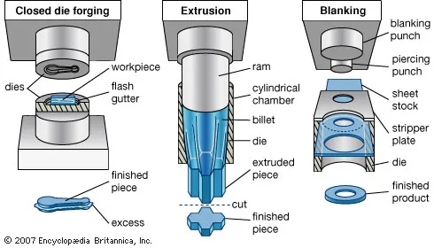
И така, какво всъщност правят матриците по време на производствения процес? В основата си тези инструменти извършват три основни операции:
- Сглобяване: Операциите по изрязване и пробиване премахват материал, за да се създадат определени контури или отвори
- Оформяне: Операциите по огъване, разтягане и изтегляне оформят материала, без да го премахват
- Комбинирани операции: Много матрици извършват множество операции в един-единствен ход на пресата
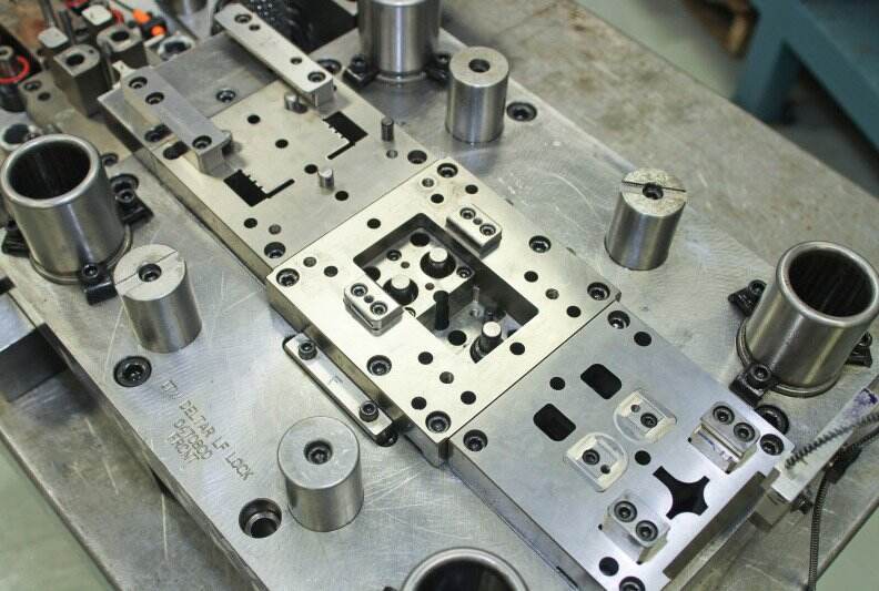
Определението, което професионалистите използват, обхваща тази универсалност. Типичен комплект матрици съдържа почти дузина компоненти — включително плочата за пробиване, матричния блок, отстраняващата плоча и водачите, — всички те работят заедно, за да осигурят точни и повтаряеми резултати. Пробивният инструмент извършва операции по разтягане, огъване или изрязване, докато матричният блок здраво стиска заготовката и осигурява съответстващата кухина.
Защо матриците са незаменими за съвременното производство
Производството на матрици засяга практически всяка индустрия, която можете да си представите. В автомобилната промишленост матриците се използват за изработване на каросерийни панели, конструктивни компоненти и части от шасито с точността, изисквана от стандартите за безопасност. Производителите на авиационна техника разчитат на специализирани матрици за леки, но изключително здрави компоненти. Електронните компании ги използват за производство на миниатюрни конектори и корпуси, докато производителите на потребителски стоки използват тях за изработване на всичко — от части за битова техника до опаковки.
Какво прави този процес толкова ценен? Бързина и последователност. Веднъж щом е създадена матрица за конкретно приложение, тя може да произвежда хиляди — дори милиони — идентични части ефективно. Тази възможност за производство в голям обем прави изработката на матрици икономически изгодна за серийно производство, където ръчното изработване би било непрактично. Първоначалните инвестиции в инструментариума се възвръщат чрез по-бързи производствени цикли и намаляващи разходи по част от времето.
Видове матрици и техните промишлени приложения
Сега, когато сте разбрали каква е функцията на една матрица, следващият въпрос естествено е: кой тип матрица трябва да използвате за вашия конкретен проект? Изборът на подходяща штемпелова матрица може да означава разликата между икономически изгодно производство и скъпо несъответствие между инструментариума и изискванията. Нека разгледаме основните видове матрици и да проучим кога всеки от тях е най-подходящ.
Прогресивни и трансферни матрици за производство в голям обем
Когато вашите производствени изисквания предвиждат хиляди или дори милиони части, прогресивни шаблони и трансферни шаблони станат вашите основни решения. Но каква е разликата между тях и кога трябва да изберете един от тях?
Прогресивни матрици работят чрез серия последователни станции, като всяка извършва конкретна операция, докато металният лист напредва през пресата. Представете си конвейерна лента на прецизността — при всеки ход материала се придвижва напред и преминава през рязане, огъване или формоване на различните етапи, докато в края се получи готовата детайл. Според Larson Tool прогресивните шаблони са известни с по-високите първоначални разходи за проектиране и изработка на инструментите, но разходите за отделна детайл намаляват значително при големи серийни производствени обеми.
Какво прави шаблоните за метално штамповане, конфигурирани като прогресивни инструменти, толкова ефективни? Разгледайте следните предимства:
- Непрекъснатата работа минимизира времето за работа между етапите
- Сложни геометрии могат да бъдат постигнати чрез множество прости операции
- Еднородността се запазва постоянна за всички произведени компоненти
- Високоскоростното производство отговаря на нуждите на индустрии като автомобилната и електрониката
Трансферни матрици от друга страна, преместват заготовката независимо между станциите чрез механични трансферни системи. За разлика от прогресивните матрици, при които лентата остава свързана, трансферните матрици физически преместват всяка детайла от една операция към следващата. Този подход работи изключително добре за по-големи или по-сложни детайли, които биха били трудни за запазване в свързано състояние по време на прогресивни операции.
Кога е по-целесъобразно да се използва трансферна матрица? Помислете за компоненти за аерокосмическата промишленост или части за тежка техника — приложения, при които големината, сложността или необходимостта от дълбоко изтегляне правят прогресивното инструментално оснащение непрактично. Контролираният трансферен процес осигурява висока точност дори при обработката на сложни сглобки, които изискват множество формообразуващи стъпки.
Компаундни, комбинирани и специални конфигурации на матрици
Не всеки проект изисква сложността на прогресивни или трансферни инструментални матрици. Понякога по-простите решения осигуряват по-голяма стойност — особено когато обемите на производството са умерени или геометрията на детайла е проста.
Комбинирани штампи извършват множество операции при един ход на пресата. Представете си изрязването на външната форма едновременно с пробиването на вътрешни отвори — всичко това става едновременно. Както обяснява JBC Technologies, компаунд-матриците произвеждат пълен бланк в една станция при всеки ход, като по този начин се избягва необходимостта от вторични процеси или ръчна инспекция на детайлите веднага след завършването им.
Прелестта на компаунд-матриците се крие в тяхната ефективност за проекти със среден обем. Те обикновено са по-евтини за проектиране в сравнение с прогресивните матрици, но все пак осигуряват резултати с висока прецизност. Режещото действие — а не деформацията — води до по-чисти ръбове и по-равни детайли направо от пресата. Това ги прави идеални за електрическа изолация, твърди филми и приложения, изискващи висока механична точност.
Комбинирани матрици предлагат гъвкавост чрез включване на различни функции на матрицата в един и същ инструмент. Те могат да комбинират рязане с формовъчни операции, което позволява на производителите да адаптират една и съща основна инструментална оснастка към променящите се производствени нужди. Тази гъвкавост се оказва ценна, когато продуктовите линии се развиват или когато трябва да се максимизира инвестициите в инструменталната оснастка за множество варианти на детайли.
За по-меки материали стоманени ножови матрици представляват икономически ефективно решение. Те използват нож с клиновидна форма за пробиване на материали като уплътнения, пяна или тънки пластмаси. Въпреки че са по-малко подходящи за твърди метали или високи обеми, стоманените линейни матрици осигуряват бързо изпълнение и по-ниски първоначални инвестиции — идеални за прототипиране или по-кратки серийни производствени серии.
Съвпадащи метални шаблони стъпка напред, когато изискванията за прецизност надхвърлят възможностите на инструментите за рязане със стоманена линийка. Като комбинират компоненти от стоманена линийка със съответстващи метални компоненти, тези хибридни решения изрязват по-малко детайлирани външни контури със стоманена линийка, докато използват съответстващи метални компоненти за сложни вътрешни форми. Матриците и штамповите приложения, които изискват строги допуски за сложни геометрии, значително се възползват от този подход.
| Тип чип | Най-добри приложения | Пригодност за производствения обем | Ниво на сложност |
|---|---|---|---|
| Прогресивни матрици | Автомобилни скоби, клипове, електронни компоненти | Голям обем (100 000+ детайла) | Високо — множество последователни станции |
| Трансферни матрици | Големи структурни части, дълбоко изтеглени компоненти, аерокосмически сглобки | Среден до висок обем | Високо — независимо прехвърляне на детайлите между станциите |
| Комбинирани штампи | Плоски части, изискващи едновременно рязане и пробиване, електрическа изолация | Средни серии | Умерено — многооперационен единичен ход |
| Комбинирани матрици | Детайли, изискващи смесено рязане и формоване, адаптивни производствени линии | Нисък до среден обем | Умерено — гъвкава конфигурация |
| Стоманени ножови матрици | Уплътнения, пяна, тънки пластмаси, прототипи | Нисък до среден обем | Ниско — направо рязане с нож |
| Съвпадащи метални шаблони | Сложни форми в твърди материали, прецизни компоненти | Среден до висок обем | Умерено до високо — хибридна конструкция |
Изборът на подходящите штампови шаблони в крайна сметка се свежда до съпоставяне на изискванията за производство с предимствата на всеки тип шаблон. Имайте предвид сложността на детайлите, очакваните обеми, спецификациите на материала и бюджетните ограничения. Решението за инструментариум, взето днес, ще повлияе на разходите ви за всяко отделно детайло и на последователността на качеството в продължение на години — което прави този избор един от най-важните в производствения ви процес.
Пълен работен процес за производство на матрици
Някога ли сте се чудили как се изработва шаблон от начало до край? Пътят от суровата стомана до прецизната инструментална оснастка включва далеч повече от просто рязане на метал в определена форма. Изработката на шаблони е сложен процес , многоетапен процес, при който всеки етап се основава на предишния — и където една-единствена грешка може да компрометира целия шаблон. Разбирането на този работен процес ви помага да осъзнаете защо качествените шаблони се предлагат по премиални цени и защо опростяването на стъпките неизбежно води до производствени проблеми по-нататък.
Процесът за изработка на шаблон обикновено продължава седмици или дори месеци, в зависимост от сложността му. Нека прегледаме всеки етап, за да знаете точно какво се случва зад кулисите, когато вашата поръчка за шаблони достигне производствения под,
- Дизайн и инженерство чрез CAD моделиране: Всеки шаблон започва като цифров концепт. Инженерите използват софтуер за компютърно подпомогнато проектиране (CAD), за да създадат подробни 3D модели, които отразяват всяко измерение, допуск и характеристика. Тази фаза на чертане на шаблона взема предвид материала, който ще бъде формиран, необходимата геометрия на детайла, спецификациите на пресата и очакванията относно обема на производството. Често се извършват множество итерации на дизайна, преди моделът да бъде одобрен.
- CAE симулация за анализ на напрежения: Преди да се извърши каквато и да е рязане на метал, софтуерът за компютърно подпомогнато инженерство (CAE) симулира начина, по който ще работи матрицата в реални условия. Анализът на напреженията идентифицира потенциалните слаби точки, докато симулациите на формоването предвиждат движението на материала и отбелязват рисковете от дефекти като гънки, намаляване на дебелината или еластична деформация. Това виртуално тестване спестява значително време и пари, като открива проблемите още преди те да се проявят физически.
- Програмиране с CAM за обработвани пътища: След като проектът успее при симулацията, програмистите по компютърно подпомогнато производство (CAM) превръщат 3D модела в прецизни траектории на режещия инструмент. Тези инструкции точно определят как трябва да се движи CNC машината, с какви скорости и с кои режещи инструменти. Оптимизираното програмиране балансира ефективността на обработката с изискванията към качеството на повърхността.
- ЧПУ обработка на компонентите на матрицата: Физическата трансформация започва тук. Фрезите с ЧПУ отстраняват голямо количество материал от стоманени блокове, за да създадат основните форми на матриците. Съвременните операции по обработка на матрици чрез фрезоване постигат забележителна прецизност — често в рамките на хилядни части от инча — благодарение на многосоставни движения и стратегии за високоскоростно рязане. Сложни геометрични форми, които някога изискваха обемна ръчна обработка, сега се получават директно от машината.
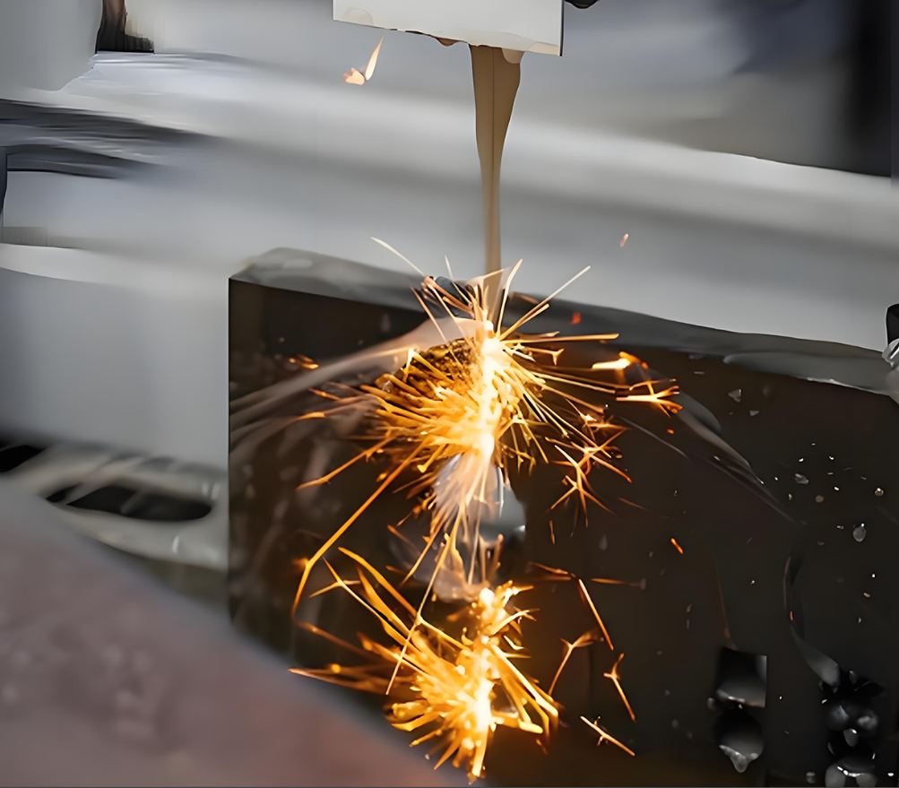
- Процеси на електроерозионно фрезоване за фини детайли: Когато конвенционалните режещи инструменти не могат да достигнат определени области или когато са необходими изключително тесни допуски, в действие влизат процесите на електроерозионно фрезоване (EDM). Този безконтактен процес разрушава материала чрез контролирани електрически искри и позволява изработването на детайли, които е невъзможно да се постигнат чрез традиционно фрезоване.
- Термична обработка за твърдост: Суровата обработена стомана няма твърдостта, необходима за производствена употреба. Термичната обработка — обикновено включваща нагряване до определени температури, последвано от контролирано охлаждане — променя металургичната структура на матрицата. Разпространени методи са закаляването, отпускането и повърхностното закаляване, като всеки от тях се подбира според марката стомана и изискванията на приложението.
- Прецисионно шлифоване и довършителна обработка: След термичната обработка матриците се подлагат на шлифоване, за да се постигнат окончателните размери и изисквания към повърхността. Равните повърхности се шлифоват до огледален блясък, докато контурните участъци могат да бъдат полирани или подложени на специализирани покрития. Тези завършващи етапи оказват пряко влияние върху качеството на детайлите и продължителността на експлоатацията на матрицата.
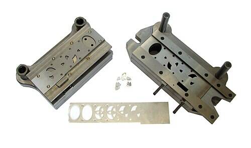
- Окончателна сглобка и пробни изпитания: Отделните компоненти се сглобяват в пълната матрица. Пробойниците, матричните блокове, отстраняващите плочи и системите за насочване трябва да са идеално подравнени. Сглобената матрица след това се подлага на пробни изпитания — реални тестови цикли, които потвърждават нейната работоспособност и позволяват окончателни корекции преди пускането ѝ в серийно производство.
От CAD проектиране до CNC машинна обработка
Предният етап на изработването на инструментални форми силно разчита на цифровото инженерство. Съвременните CAD системи правят далеч повече от това да създават привлекателни изображения — те създават интелигентни модели, съдържащи свойства на материала, натрупвания на допуски и производствени ограничения. Когато инженерите променят един елемент, системата автоматично актуализира свързаните размери в целия проект.
Защо това има значение за вашия проект? Защото възможностите за симулация означават по-малко изненади по време на производството. CAE софтуерът може да моделира операциите по формоване, да предвижда къде материалът може да се напука или да се набръчка и да оптимизира формата на заготовките за по-ефективно използване на материала. Според експерти от отрасъла този етап на проектиране включва определяне на необходимите допуски, изчисляване на силите при формоване и избор на подходящи материали въз основа на производствените изисквания.
Самият процес на машинна обработка се е развил драматично благодарение на технологиите за числов контрол (CNC). Многоосевите машини могат да се приближават към заготовките от практически всеки ъгъл, създавайки подрязвания и сложни контури в един-единствен монтаж. Стратегиите за високоскоростна обработка комбинират леки резове с бързи движения, за да се постигнат отлични повърхностни качества, като едновременно с това се минимизира натрупването на топлина, което би могло да повлияе върху материалните свойства.
Процеси за електроерозионна обработка (EDM) и техники за прецизна финиш обработка
Тук обработката на матрици става истински специализирана. Технологията за електроерозионна обработка (EDM) позволява изработването на елементи, които конвенционалната машинна обработка просто не може да осъществи — а разбирането на различните методи за EDM помага да се оцени защо някои матрици струват повече от други.
Телен EDM използва непрекъснато подаван жиросен електрод от медна сплав. Жицата преминава през обработваната детайл, докато е потопена в деионизирана вода, и изрязва прецизни профили с допуски, измервани в микрометри. Според YCM Alliance, телена EDM-обработка се отличава с изключителна точност при пробиване на цели отвори и произвежда ръбове без заешки крачета, готови за сглобяване. Тази технология често се използва за производството на матрици, отвори в шаблони и прецизни плочи.
Синкер EDM (също наричана „die-sinking“ или „ram EDM“) работи по различен начин. Формован електрод — обикновено от графит или мед — се вмъква в обработваната детайл, като възпроизвежда нейната геометрия в обратен ред. Този процес създава затворени кухини, сложни триизмерни форми и остри вътрешни ъгли, които фрезите просто не могат да достигнат. Диелектричната течност отстранява отпадъците, докато сервоконтролите поддържат прецизни разстояния между искрите.
Small hole edm специализира се в създаването на миниатюрни, дълбоки отвори за охладителни канали и отдушни отвори. Тези проходи са от съществено значение за управлението на топлината по време на производството, но е невъзможно да се пробият по конвенционален начин поради високото си съотношение дълбочина-диаметър.
Какво прави ЕДМ толкова ценен за изработката на матрици? Неконтактният характер на процеса означава, че върху заготовката не действат никакви резултантни сили. Закалени стомани, карбиди и екзотични сплави се обработват също толкова лесно, колкото и по-меките материали. Зоните, засегнати от топлината, остават малки и контролируеми, което запазва металургичните свойства, установени по време на термичната обработка.
След механичната обработка и операциите с електроерозионна обработка (ЕДМ) повърхностната финишна обработка довежда матрицата до състояние, готово за производство. Операциите по шлифоване осигуряват равността и успоредността, критични за правилното функциониране на пресата. Полирането намалява триенето и предотвратява прилепването на материала по време на формовъчните операции. При някои приложения се изискват специализирани покрития — нитрид на титан, диамантоподобен въглерод или други обработки, — които удължават живота на матрицата и подобряват отделянето на детайлите.
Етапът на окончателната сглобка обединява всичко. Всеки компонент трябва да се побере точно в съответстващите му части. Елементите за подравняване, насочващите системи и пружинните механизми изискват внимателна настройка. Само след успешни пробни пускове — при които матрицата действително произвежда пробни детайли — инструментът получава одобрение за употреба в серийно производство.
Сега, когато производственият процес е ясен, следващото критично решение е изборът на подходящите материали за компонентите на вашата матрица — решение, което директно влияе върху срока на експлоатация на инструмента, изискванията за поддръжка и, в крайна сметка, върху разходите ви за всяко отделно детайл.
Избор на материали за матрици и обяснение на стоманени класове
Вече сте видели как се проектират и произвеждат матриците — но какво да кажем за материалите, които ги правят функционални? Изборът на подходяща стомана за матрици или вмъкнат материал е едно от най-важните решения в производството на матрици. Направете правилния избор и вашето инструментално оборудване ще произвежда стотици хиляди прецизни детайли. Направите погрешен избор и ще се сблъскате с преждевременно износване, неочаквани повреди и скъпи прекъсвания в производствения процес.
Така какво всъщност представлява изборът на материали за инструменти и матрици? Той се свежда до съчетаване на металургичните свойства с конкретните ви производствени изисквания. Понятието „инструменти и матрици“ надхвърля самото физическо инструментално оборудване — то включва внимателното инженерно проектиране на избора на материали, който осигурява баланс между устойчивостта към износване, ударопрочността, обработваемостта и разходите.
Класове инструментална стомана и техните експлоатационни характеристики
Не всяка стомана за матрици има еднакви характеристики. Различните марки се отличават в различни приложения, а разбирането на тези различия ви помага да определите подходящия материал за вашите изисквания към инструменталното оборудване за матрици.
D2 инструментална стомана се отличава като работна коня за устойчивост на износване. С приблизително 12% съдържание на хром, стоманата D2 развива изключителна твърдост (обикновено 58–62 HRC след термична обработка) и по-добре устойчива на абразивно износване в сравнение с повечето алтернативи. Според Worthy Hardware, D2 е класически избор за матрици и пробойници, които изискват много висока устойчивост на износване. Тази твърдост обаче има и своя цена — D2 е по-трудна за машинна обработка и по-крехка в сравнение с по-удароустойчивите марки.
Инструментална стомана A2 предлага отлично равновесие между устойчивост на износване и обработваемост. Тя се закалява на въздух, което намалява деформацията по време на термична обработка — значително предимство за прецизни метални компоненти на матрици. A2 обикновено достига твърдост 57–62 HRC и се обработва по-лесно от D2, което я прави универсален избор за общи приложения в штамповката, където имат значение как експлоатационните характеристики, така и възможностите за производство.
S7 инструментална стомана специализира се в устойчивост на ударни натоварвания. Когато вашите матрични компоненти трябва да издържат повтарящи се високоинтензивни натоварвания, без да се чупят или пукат, S7 осигурява изключителна производителност. Както отбелязват експертите от индустрията, S7 е известна със своята забележителна ударна здравина, която се дължи на по-ниското съдържание на въглерод и допринася за изключителна твърдост. Това я прави идеална за пробойници, резачи и компоненти, които изпитват внезапни и интензивни сили по време на формовъчни операции.
H13 инструментална стомана изcellира в приложения за гореща обработка. Ако производството на вашите матрици включва високи температури — например горещо клеймо или леене в матрица — H13 запазва своята здравина и твърдост там, където други стомани биха се размекнали. Нейната устойчивост към термична умора предотвратява образуването на топлинни пукнатини, които с времето разрушават по-нискокачествени материали.
Съответствие между материала на матрицата и производствените изисквания
Освен инструменталните стомани, матричните компоненти често включват специализирани материали за конкретни функции. Според Header Die & Tool , изборът между материали като стомана и карбидни вставки може да окаже значително влияние върху способността на производителя на инструменти да предоставя надеждни продукти.
Вставки от карбид осигуряват изключителна устойчивост на износване за производство в големи обеми. Волфрамовият карбид — наличен в различни класове според съдържанието на кобалт — има срок на служба, който надвишава този на стоманените вставки с коефициент от 10 или повече в изискващи приложения. Компромисът? По-висока първоначална цена и намалена здравина. При увеличаване на съдържанието на кобалт (обикновено от 6 % до 25 %) твърдостта намалява, докато устойчивостта към удар се подобрява. Това означава, че можете да подбирате подходящия карбид според конкретните компоненти на матрицата и условията на производството.
Сплави на бронз изпълняват ключови функции като водещи компоненти, втулки и плочи за износване. Тяхната самосмазваща се способност намалява триенето там, където компонентите на матрицата се плъзгат един по друг, удължавайки живота на инструмента и запазвайки точността на подравняването през целия производствен цикъл.
При избора на материали вземете предвид следните ключови фактори:
- Обем на производството: По-високите обеми оправдават използването на премиални материали като карбид, които осигуряват по-продължителен експлоатационен живот
- Материалът, който се оформя: Абразивните материали като неръждаемата стомана изискват по-твърди повърхности на матриците в сравнение с приложенията с мека стомана
- Изисквани допуски: По-строгите допуски изискват стабилни, устойчиви на износване материали, които запазват размерите си по-дълго
- Бюджетни ограничения: Балансирайте първоначалните разходи за материали с общата стойност на притежанието, включително поддръжка и замяна
| Марка на материала | Основни характеристики | Най-добри приложения | Относителна цена |
|---|---|---|---|
| D2 инструментална стомана | Изключителна устойчивост на износване, висока твърдост (58–62 HRC), добра запазваемост на ръба | Резачни матрици, пробивни пулове, матрици за продължително штамповане | Умерена |
| Инструментална стомана A2 | Балансирана устойчивост на износване и ударна здравина, закаляване на въздух, добра обработваемост | Матрици за обща употреба, формовъчни инструменти, универсални приложения | Умерена |
| S7 инструментална стомана | Изключителна устойчивост на ударни натоварвания, висока ударна здравина, умерена устойчивост на износване | Тежки пробивни пулове, ножове за рязане, компоненти, подложени на ударни натоварвания | Умерена |
| H13 инструментална стомана | Твърдост при високи температури, устойчивост на термична умора, размерна стабилност при високи температури | Матрици за горещо штамповане, леярски матрици, формовъчни процеси при повишени температури | Средно-висок |
| Тунгътен карбид | Екстремна устойчивост на износване, висока твърдост, отлично размерно състояние | Производство в големи обеми, абразивни материали, критични зони на износване | Високо |
| Сплави на бронз | Самосмазващ се, с ниско триене, добри свойства на износване при контакт със стомана | Ръководни бушони, плочи за износване, плъзгащи се компоненти | Умерена |
Правилният избор на материал директно влияе върху работната област на вашата матрица. Матрицата, изработена от подходящи материали за предвиденото й приложение, ще запази допуските по-дълго, ще изисква по-рядка поддръжка и в крайна сметка ще осигури по-ниски разходи на част през целия й производствен живот. След като са избрани материалите, следващото критично съображение е как проектните решения превръщат тези материални свойства в оптимална производителност на матрицата.
Принципи за проектиране на матрици за оптимална производителност
Избрали сте своите материали и разбирате производствения процес — но точно тук започва истинското инженерство. Принципите за проектиране на шаблони определят дали вашата оснастка ще произвежда последователни, висококачествени детайли или ще се превърне в източник на безкрайни производствени проблеми. Решенията, взети по време на фазата на проектиране, оказват влияние върху всеки последващ производствен цикъл, като засягат размерната точност, повърхностната обработка и, в крайна сметка, вашата печалба.
Какво отличава добрия шаблон от отличния? Това се свежда до разбирането как всеки елемент от проектирането — от зазорите между пробойника и матрицата до подредбата на лентата — работи заедно като интегрирана система. Нека разгледаме критичните принципи, на които разчитат специалистите по производство, за да създадат оснастка, която функционира безупречно при изискващи производствени условия.
Критични зазори и стандарти за допуски
Когато матричен пробойник принуждава материала да мине през отвора на матрицата, разстоянието между тези режещи ръбове определя всичко свързано с качеството на рязането ви. Според MISUMI, зазорът е разстоянието между режещия ръб на пробойника и режещия ръб на матричната кутия — и представлява оптималното разстояние, необходимо за пробиване на материала чрез срязване и изработване на чист отвор.
Звучи просто, нали? Тук нещата стават по-тонки. Зазорът се задава като процент на всяка страна, т.е. зазорът, наличен във всеки ръб на повърхността на рязането, като функция от дебелината на заготовката. Например препоръчителният зазор от 10 % означава, че от всяка страна трябва да има зазор, равен на 10 % от дебелината на материала. Ако го изчислите погрешно, последствията ще се проявят незабавно върху вашите детайли.
Какви са последствията от неправилен зазор?
- Излишни заострени ръбове (бурини), които изискват време-емка вторична ръчна обработка
- Деформация на материала и непостоянни режещи ръбове
- Ускорено износване на пробойниците и матриците
- Възможна фрактура на компонентите на инструментите — създава опасности за безопасността
- Увеличено енергопотребление от пресата
Материалът на заготовката определя първо вашите решения относно зазорите. По-силните и по-твърди материали изискват по-големи зазори в сравнение с по-слабите и по-меки алтернативи. Важно е и дебелината — по-дебелите материали изискват допълнително разстояние. Като обща насока стандартният препоръчителен зазор е около 10 % от дебелината на материала от всяка страна, макар съвременното производство често препоръчва 11–20 % за намаляване на натоварването върху инструментите и удължаване на техния експлоатационен живот.
За специализирани приложения като финото шперцоване — където изключителната размерна точност и качеството на ръба на реза са от първостепенно значение — се изискват много малки зазори. Плочата на пресата и заготовката трябва да бъдат строго ограничени, за да се предотврати пластичната деформация, но тази прецизност има своя цена: финото шперцоване е износващо за производствените инструменти поради тези изключително тесни допуски.
Дизайнерски решения, които влияят върху качеството на детайлите
Освен допуските, няколко взаимосвързани елемента на конструкцията определят производителната ефективност на вашата матрица. Всяко взето решение поражда верига от последствия през цялата производствена операция.
Оптимизация на разположението на лентата непосредствено влияе върху вашите разходи за материали. Според отраслени указания проектирането на разположението на лентата за прогресивни матрици има за цел да максимизира използването на материала — често се цели над 75 % ефективност — и едновременно с това да минимизира отпадъците. Разположението определя начина, по който детайлите се подреждат върху лентата, последователността на операциите и, в крайна сметка, колко суров материал се превръща в готов продукт спрямо отпадъците.
Ключови изчисления при проектиране на разположението на лентата включват определяне на дебелината на мостчето — малкия участък материал, оставащ между отделните детайли. Често използвана формула изхожда от дебелината на материала (t): дебелината на мостчето обикновено варира между 1,25t и 1,5t. Тази изглеждаща незначителна подробност предотвратява завъртането и заклещването на отпадъците в матрицата, като същевременно остава достатъчно здрава, за да пренася детайлите напред през прогресивните станции.
Системи за пилоти и водачи осигуряват точност на подравняването през целия цикъл на штамповане. Ръководните штифтове на матрицата работят в съчетание с ръководни бушони, за да подравнят горната и долната матрични плочи с висока точност — често се произвеждат с допуски в рамките на 0,0001 инча. Ръководните штифтове с топлинни кугли са станали индустриален стандарт, тъй като се разделят по-лесно и осигуряват последователно насочване, докато триещите штифтове все още се използват в специфични приложения, изискващи максимална твърдост.
Избор на пружини за изтеглящи плочи влияе върху начина, по който материала се отделя от пробива след всяка операция. Матричните пружини — обикновено спираловидни пружини за компресия с висока сила — осигуряват необходимата сила, за да задържат металните листове на място по време на формоването, като едновременно позволяват чисто изхвърляне след това. Изборът между механични жироспирални пружини и азотни газови пружини зависи от изискванията към силата, ограниченията по отношение на пространството и съображенията за поддръжка.
Ето основните принципи за проектиране на матрици, които всеки инженер трябва да следва:
- Изчисляване на зазорите въз основа както на свойствата на материала, така и на неговата дебелина —по-твърдите материали и по-дебелите листове изискват увеличено разстояние между повърхностите за пробиване и отворите на матрицата
- Оптимизирайте разположението на лентите за по-ефективно използване на материала —разгледайте ъгловото подреждане или многостепенните стратегии, когато геометрията на детайлите го позволява
- Изберете конструкции на носещи ленти, подходящи за операциите по формоване —цели носещи ленти за плоски детайли, носещи ленти с еластична мрежа за детайли, които изискват вертикално преместване или дълбоко изтегляне
- Задайте компоненти за насочване според вашите изисквания към прецизността —по-тесните допуски изискват по-висококачествени насочващи пинове и втулки
- Размерирайте пружините правилно според силите за отделяне —недостатъчното налягане на пружините води до проблеми с изваждането на отпадъците и прихващането им
- Проектирайте за лесен достъп при поддръжка —компонентите, които се износват, изискват проста процедура за замяна
- Включване на валидация чрез симулация —софтуерът за компютърно подпомогнато инженерство (CAE) идентифицира потенциални дефекти като пукнатини, гънки или еластично връщане още преди рязането на стомана
Всяко решение, взето по време на проектирането, има пряка връзка с производствените резултати. Добре проектираната матрица за пресови приложения не само произвежда детайли — тя произвежда последователни детайли ефективно, с минимални отпадъци и удължени интервали между техническото обслужване. Първоначалните инвестиции в правилно проектиране се възвръщат многократно през милиони производствени цикли.
След като принципите на проектирането са установени, следващата критична стъпка гарантира, че вашата оснастка действително изпълнява поставените й задачи. Стандартите за контрол на качеството и инспекцията потвърждават, че всеки размер, повърхност и сборка отговарят на спецификациите, изисквани от вашето производство.
Стандарти за контрол на качеството и инспекция на матриците
Шаблонът ви е проектиран, изработен и сглобен — но как можете да бъдете сигурни, че ще работи наистина в производствените условия? Контролът на качеството изпълнява ролята на последна бариера между инвестициите ви в инструменти и успеха на производствения подов. В света на производството на шаблони дори микроскопичните отклонения могат да доведат до отхвърлени детайли, неочаквани простои и недоволни клиенти. Разбирането на методите за инспекция и подходите за диагностика разграничава производителите, които само се надяват шаблоните им да работят, от тези, които са сигурни в тяхната функционалност.
Индустрията за производство на шаблони е развила сложни протоколи за верификация, които откриват проблемите, преди те да се превърнат в скъпи производствени провали. Нека разгледаме техниките, които гарантират съответствието на вашия инструментален шаблон на зададените спецификации — и какво трябва да се направи, когато възникнат проблеми с производителността.
Методи за инспекция и проверка на допуските
Размерният контрол започва с координатни измервателни машини (CMM) — златният стандарт за проверка на геометрията на матриците спрямо проектните спецификации. Тези системи използват прецизни зонди за картографиране на повърхности и елементи в тримерно пространство, като сравняват действителните измервания с CAD модели с точност до микрометър.
Според Keyence съвременната технология за CMM интегрира множество методи за измерване в рамките на единна платформа. Контактните зонди работят добре при големи и твърди компоненти, докато безконтактното лазерно сканиране бързо регистрира сложни повърхностни геометрии. Този хибриден подход отстранява временни ограничения и подобрява ефективността на измерванията — особено важно при контрола на машинни матрици с изключително сложни елементи.
Какви конкретни елементи изискват верификация? Критичните елементи на матрицата включват:
- Външни повърхности: Правилните пропорции и форми трябва да съответстват на проектната цел
- Вътрешни канали: Точните размери гарантират структурната цялост и ефективността на охлаждането
- Монтажни отвори и точки за свързване: Правилното позициониране гарантира съвместимост при сглобяването
- Стена на тръбата: Предотвратява зони с повишена склонност към повреда в областите за формоване
- Равнинност, перпендикулярност и концентричност: Геометричните взаимовръзки влияят върху функционирането на матрицата
Освен проверките на размерите, верификацията на повърхностната шерохватост потвърждава, че формователните повърхности отговарят на изискванията за качеството на детайлите и продължителността на живота на матрицата. Профилометрите измерват стойностите на шерохватостта, докато визуалният инспекционен контрол открива драскотини, следи от инструменти или дефекти от полиране, които биха могли да се пренесат върху штамповани детайли.
Протоколите за твърдостни изпитвания потвърждават, че термичната обработка е постигнала целевите спецификации. Изпитвания за твърдост по Рокуел или Викерс на множество места потвърждават равномерното закаляване по цялата дължина на критичните компоненти на матрицата. Неравномерната твърдост сочи проблеми с термичната обработка, които намаляват устойчивостта към износване и сроковете на експлоатация на инструмента.
Процедурата за пробно използване на матрицата представлява окончателната валидация. Според подробностите, предоставени от експерти по штамповане в автомобилната промишленост, пробното използване е интензивен етап на финна настройка, при който новопроизведената матрица произвежда първите си части при реални условия на преса. Този итеративен процес включва штамповане на пробни изделия, инспекция за дефекти и извършване на прецизни корекции, докато матрицата последователно не започне да произвежда части, отговарящи на всички спецификации.
Контролни точки за качество в цялата матрична индустрия следват установени протоколи:
- Проверка с координатно-измерителна машина (CMM) на всички критични размери спрямо допуските в CAD
- Измерване на повърхностната шлифовка върху формиращи и износващи повърхности
- Твърдостни изпитания на множество места в компонентите, подложени на термична обработка
- Визуална инспекция за дефекти от машинна обработка, заострени ръбове или повърхностни повреди
- Проверка на сглобяването, потвърждаваща правилното прилягане и подравняване на компонентите
- Пробни изпълнения, произвеждащи пробни части за размерна и визуална оценка
- Статистически проучвания за способността на процеса, потвърждаващи повторяемостта на производството
Отстраняване на често срещани проблеми с производителността на матриците
Дори добре изработените матрици срещат предизвикателства в производствения процес. Разбирането на често срещаните проблеми и техните коренни причини позволява по-бързо тяхното отстраняване и предотвратява повторното им възникване, което би нарушило вашата производствена дейност.
Шаблони на износ тези проблеми се развиват в течение на производствените цикли и в крайна сметка засягат качеството на детайлите. Според Gromax Precision леки тенденции като увеличаващи се зауси или постепенно отклоняващи се размери често показват започващото износване още преди да са настъпили очевидни повреди. Съвременните подходи използват статистически контрол на процеса (SPC), подпомогнат от изкуствен интелект, за по-ранно откриване на такива закономерности в сравнение с ръчната инспекция. Мониторингът на тенденциите в натиска осигурява допълнително ранно предупреждение — бавното увеличаване на необходимата пресова сила често е признак за затъпяване на инструментите или за развиваща се несъосаност.
Въпроси за съгласуване се проявяват като непоследователни размери на детайлите, неравномерен износ на повърхностите на пуансона и матрицата или преждевременно повреждане на инструментите. Износът на насочващите пинове и втулките води до постепенно разместване, което се усилва с времето. Редовната проверка на насочващите компоненти — и замяната им въз основа на измерения износ, а не според произволни графици — предотвратява проблеми с качеството, свързани с подравняването.
Проблеми с материала при формоване предизвикват дефекти като набръчкване, разкъсване или непълно формоване. Набръчкването показва недостатъчно налягане от държача на заготовката, което позволява на листовия метал да се огъне, докато разкъсването възниква, когато материала се удължи над границите на неговата формователна способност. Както е отбелязано в документацията за пробното използване на матрицата, коригирането на тези проблеми често изисква настройка на влечещите ръбове или модифициране на допълнителните елементи, които контролират подаването на материала в кухината на матрицата.
Връщане след извиване предизвикателствата стават по-значими при високопрочните материали. След формирането налягането се разтоварва и еластичното възстановяване кара детайлите да отклоняват от предвидените размери. Прогнозирането и компенсирането на това явление често изисква няколко итерации на корекция на повърхността на матрицата — прегъване на детайла в малка степен над необходимото, за да се върне обратно в правилната окончателна форма.
Превентивното поддържане, базирано на данни, а не на интуиция, предотвратява много проблеми, преди те да повлияят на производствения процес. Броят на удари, проследяването на консумацията на руло и прогнозното моделиране позволяват графици за превентивно поддържане, които отстраняват износването, преди допуските да се отклонят в недопустима степен. Вградените системи за визуална инспекция откриват микроскопични промени в размерите в реално време и идентифицират проблемите, докато производството продължава, вместо да чакат отхвърлянето на продуктите в края на производствената линия.
Проверката на качеството не свършва, когато матрицата бъде изпратена за производство. Непрекъснатото функциониране на матрицата изисква непрекъснато наблюдение, периодична повторна инспекция и документирани протоколи за поддръжка. Този подход, основан на целия жизнен цикъл, гарантира, че инвестициите ви в инструментариум ще осигуряват последователни резултати през целия срок на неговата експлоатация — което ни води до начина, по който тези прецизни инструменти се прилагат в реални автомобилни приложения.
Автомобилни штемпеловъчни матрици и изисквания на производителите на оригинален оборудван (OEM)
Ако имаме предвид, че един съвременен автомобил съдържа хиляди точно оформени метални компоненти, мащабът на производството на инструменти и матрици за автомобилни приложения става поразяващ. От извития капак, който привлича погледа ви, до конструктивните усилващи елементи, които защитават пътниците при сблъскване, производството на штемпеловъчни матрици осигурява прецизността и последователността, които производителите на оригинален автомобилно оборудван (OEM) изискват. Но как матриците в производствения процес превръщат инженерните проекти в надеждни компоненти, които напускат производствените линии по целия свят?
Автомобилната индустрия представлява една от най-изискващите среди за производството на шаблони. Всеки панел на кузовът трябва да се съчетава идеално със съседните компоненти. Всеки конструктивен елемент трябва да отговаря на строгите изисквания за безопасност. И всеки серийно производствен цикъл трябва да осигурява идентични резултати — независимо дали произвеждате първата или милионната част. Тук прецизното штамповане среща реалните предизвикателства на производството.
Прецизно штамповане за автомобилни кузовни и конструктивни части
Штамповъчните матрици за автомобилна индустрия произвеждат три основни категории компоненти, като всяка от тях има специфични изисквания, които определят техническите характеристики на производствените матрици:
Karoserни панели изискват изключително високо качество на повърхността, защото те са това, което клиентите виждат и докосват. Капаци, фендери, врати и покривни панели трябва да излизат от процеса на штамповане с повърхности от клас А — без вълнистост, текстура като портокалова кора или други видими дефекти. Според Mursix производството чрез метално штамповане осигурява прецизност, издръжливост и последователност, всичко това в големи обеми — точно това, от което се нуждае производството на кузовни панели.
Структурни компоненти поставят предимство на здравината и размерната точност пред естетиката на повърхността. B-колоните, подовите панели и напречните греди формират защитната клетка на превозното средство, абсорбирайки и насочвайки енергията от удар при сблъсък, за да защитят пътниците. Тези части все по-често се произвеждат от напреднали стомани с висока здравина (AHSS), които предизвикват традиционните методи на штамповане. По-високата граница на текучест на материала означава по-голямо еластично връщане (springback), по-строги условия за формоване и ускорено износване на штамповите матрици — всички тези фактори влияят върху решенията за производствените инструменти.
Компоненти на шасието свързват механичните системи на превозното средство, докато издържат постоянен стрес от условията на пътя. Ръчките за управление, монтажните точки на подвеската и компонентите на подрамката изискват строги допуски, за да се осигури правилна подравняване на колелата и желаните характеристики на управляемостта. Производството чрез пробиване с матрица за тези приложения трябва да взема предвид взаимодействието между множество части в сглобеното превозно средство.
Какво прави штамповката за автомобилна индустрия уникално предизвикателна?
- Сложност на материала: Съвременните превозни средства комбинират нискоуглеродна стомана, високопрочна стомана (AHSS), алуминий и дори композитни материали — всеки от които изисква специализирани подходи към изработката на матрици.
- Натрупване на допуски: Компонентите трябва да се съчетават помежду си по цялото превозно средство, което означава, че допуските за отделните части трябва да са по-строги от изискванията за крайната сглобка.
- Обеми на производството: Популярните модели могат да изискват милиони идентични части годишно, което налага изключителна издръжливост на матриците.
- Дизайнерски натиски: Дизайнерите насочват към по-сложни криви и по-остри контурни линии, които изпитват границите на технологиите за формоване.
Спазване на стандартите на производителите на оригинално оборудване (OEM) чрез напреднало инженерство на матрици
Автомобилните производители на оригинално оборудване (OEM) не просто се надяват, че доставчиците им ще осигурят качество — те изискват документирани доказателства чрез строги стандарти за сертифициране. Основата на тази система за осигуряване на качество е сертификатът IATF 16949.
Според NSF International iATF 16949 е международният стандарт за системи за управление на качеството в автомобилната промишленост и предоставя стандартизирана Система за управление на качеството (СУК), която насочва непрекъснатото подобряване, с акцент върху предотвратяването на дефекти и намаляването на вариациите и отпадъците в автомобилната верига за доставки. Повечето големи автомобилни OEM изискват този сертификат от своите партньори в веригата за доставки — което го превръща в базово изискване, а не в конкурентно предимство.
Защо IATF 16949 има особено значение именно за умиращите инструменти в производствените приложения? Стандартът изисква:
- Документирани процеси за всеки етап от разработката и производството на инструментите
- Статистически контрол на процесите за наблюдение и поддържане на последователността
- Системи за коригиращи действия, които решават причините за проблемите, а не само техните прояви
- Инициативи за непрекъснато подобряване, вградени в ежедневните операции
Над рамките на сертифицирането, CAE-симулациите са променили начина, по който се разработват штамповите матрици за автомобилна промишленост. Както е подробно описано от експертите по симулации , съвременните симулации на формоване предвиждат поведението на материала още преди да е изрязано каквото и да било стоманено парче. Инженерите могат да идентифицират потенциални дефекти — набръчкване, изтъняване, разкъсване, еластично връщане — при виртуални пробни пускове и съответно да коригират конструкцията на матриците. Този подход, базиран преди всичко на симулации, значително намалява броя на физическите пробни пускове и ускорява времето до производство.
Възможностите за бързо прототипиране са станали все по-критични, тъй като циклите на разработка на автомобили се скъсяват. Производителите на оригинално оборудване (OEM) имат нужда от прототипни части бързо, за да валидират дизайните, да извършват изпитания и да вземат решения, преди да се ангажират с производствени инструменти. Компании като Shaoyi показват как напредналите производители на шаблони реагират на тези предизвикателства — техните операции, сертифицирани според IATF 16949, осигуряват бързо прототипиране за срок от само 5 дни, като поддържат процент на одобрение при първия опит от 93 % чрез интегрирани възможности за CAE симулация.
Показателят за първоначалното одобрение представлява ключов индикатор за ефективност, който производителите на оригинално оборудване (OEM) следят внимателно. Този показател измерва колко често шаблоните произвеждат приемливи детайли при първото пробно производство, без да се налага повторна обработка или модификация. Производителите с водещо положение в отрасъла постигат показатели над 90 % чрез строга инженерна подготовка преди започване на производството — рязък контраст спрямо традиционните подходи, при които няколко цикъла на преработка се считаха за нормални. По-високите показатели за първоначално одобрение водят директно до по-бързо стартиране на програмите и намаляване на разходите за разработка.
Сливането на качествените системи IATF 16949, напредналите симулационни технологии и възможностите за бързо прототипиране определя съвременното производство на шаблони за автомобилно шампиране. Тези елементи работят заедно, за да осигурят онова, от което OEM-производителите най-накрая имат нужда: прециозни инструменти, които произвеждат последователни и висококачествени детайли още от първото серийно производство и през милиони последващи цикли.
Разбирането на тези технически и качествени изисквания естествено води до практически въпрос: каква е цената на цялата тази прецизност и как оценявате възвръщаемостта на инвестициите си в матриците?
Фактори, влияещи цената, и планиране на инвестициите за матрици
Вие вече видяхте прецизното инженерство, стоящо зад автомобилните штамповъчни матрици — но ето въпроса, който всеки мениджър по набавки и проектен инженер задава: каква е действителната цена и как да обоснова инвестициите? Производството на матрици представлява значителни първоначални разходи, но правилният избор на инструменти може радикално да намали разходите ви за отделна част през милиони производствени цикли. Разбирането на факторите, които определят цената, ви помага да правите точни бюджетни прогнози и да водите ефективни преговори с производителите на матрици.
Реалността е, че оценките за разходите за инструменти се различават значително между различните цехове — понякога с повече от 50 % за една и съща част. Според Производителят тази разлика се дължи на различия в методите за обработка, възможностите на доставчиците и начина, по който всеки производител на матрици интерпретира вашите изисквания. Един цех може да предложи прогресивна матрица с 10 станции, докато друг предлага такава с 15 станции — а тази разлика фундаментално променя цената.
Фактори, които влияят върху производствените разходи за матрици
Какво всъщност определя цената на матриците? Отговорът включва взаимосвързани променливи, които опитните компании за производство на матрици вземат под внимание при подготовката на оферти. Разбирането на тези фактори ви дава възможност да вземате обосновани решения — и потенциално да откриете възможности за намаляване на разходите.
- Тип и сложност на инструментите: Прогресивните матрици с множество станции струват повече от простите компаундни матрици. Броят на операциите, сложността на формиращите елементи и изискванията за прецизност увеличават както инженерното, така и машинното време, необходимо за производството.
- Геометрия на детайла и допуски: Сложни криви, тесни допуски и изискани конструктивни елементи изискват по-съвършено машинно обработване, допълнителни операции с електроерозионно фрезоване (EDM) и удължени цикли за пробно производство. Долната плоча за проста скоба струва значително по-малко от долната плоча за автомобилна панелна част, получена чрез дълбоко изтегляне.
- Размери на долната плоча и изисквания към материала: По-големите долните плочи изискват повече стомана, по-големи CNC машини и по-дълги цикли на машинно обработване. Детайлите, изработени от специални материали като високопрочна стомана, титан или алуминий, често изискват по-висококачествени инструментални стомани и карбидни резцови пластина — което значително увеличава разходите за материали.
- Очаквани обеми на производството: Долните плочи, проектирани за милиони детайли, изискват премиални материали, закалени вставки и здрава конструкция, което увеличава първоначалните разходи, но намалява разходите за отделно детайле с течение на времето.
- Местоположение на доставчика и нива на заплати: Производителите на долните плочи в различни региони се сблъскват с различни разходи за труд. Както отбелязват експертите от отрасъла, обикновено е по-скъпо да се изработи инструмент в Калифорния, отколкото в Уисконсин, тъй като проектирането и изработването на долните плочи е трудоемък процес.
- Товарът и капацитетът на доставчика: Магазинът, който е напълно зареден с поръчки и работи извън работно време, ще предложи по-високи цени в сравнение с този, който търси работа. Стратегичното планиране на вашите заявките за оферти може да повлияе върху ценообразуването.
- Условия за плащане: Клиентите, които плащат навреме, често получават по-конкурентни оферти. За скъпите проекти промеждутъчните плащания помагат на производителите на шаблони за рязане да управляват паричния си поток — а тази гъвкавост може да се отрази в по-добра цена.
Искате ли да минимизирате разликата между оферти? Според най-добрите практики в отрасъла, производителите на штамповани изделия трябва да определят как ще произвеждат детайла, преди да изпратят заявките си за оферти. Когато специалист по инструментално оборудване определи технологичния процес — вместо да остави това на интерпретацията на всеки доставчик — се получават по-сравними оферти и често се идентифицира най-икономичният подход още в началото.
Изчисляване на възвращаемостта от инвестициите в шаблони за рязане
Тук се разкрива истинската финансова картина. Изработката на матрици представлява първоначално инвестиране, което води до възвращаемост през целия ви производствен цикъл. Връзката между първоначалната цена и икономиката за отделна част определя дали решението ви относно матриците е финансово оправдано.
Разгледайте тази проста рамка: разделете общата цена на матрицата на очаквания обем на производството, за да определите приноса на матрицата към цената на всяка отделна част. Матрица за 200 000 щ.д. за производство на 1 милион части добавя 0,20 щ.д. към цената на всяка единица. Същата матрица, произвеждаща само 100 000 части, добавя 2,00 щ.д. към цената на всяка единица — десетократна разлика, която може да направи проекта неикономически оправдан.
Обаче първоначалната цена показва само част от историята. Според Die-Matic инвестициите в проектирането на висококачествени шаблони помагат да се гарантира точна и последователна продукция, като се минимизират както грешките, така и необходимостта от поправки. По-издръжливите шаблони изискват по-малко поддръжка и намаляват разходите за замяна през целия им експлоатационен живот. При оценката на оферти имайте предвид общата стойност на притежанието — не само първоначалната покупна цена.
Фактори в жизнения цикъл на шаблоните, които влияят върху реалния ви ROI, включват:
- Требования за поддръжка: Редовното планово поддържане предотвратява неочаквани повреди и удължава срока на експлоатация на шаблоните. Предвиждайте бюджет за периодично заостряне, замяна на компоненти и профилактични инспекции.
- Очакван живот: Шаблоните от висок клас, изработени с карбидни вставки и правилно термообработени, могат да произвеждат 5–10 пъти повече детайли от икономичните шаблони, преди да се наложи основно възстановяване.
- Възможности за възстановяване: Шаблоните не са еднократни — износените компоненти често могат да бъдат заменени или прегледани, което удължава полезния им живот при част от разходите за нови шаблони.
- Разходи за простоюване: Авария на шаблон по време на производството струва далеч повече от самия ремонт. Загубеното производство, ускореното доставяне и санкциите от страна на клиентите могат да надвишат разходите за самото инструментариум.
За практически цели при бюджетното планиране следвайте този подход: поискайте оферти от няколко производителя на шаблони, но уверете се, че всеки доставчик предлага цитиране според едни и същи технически спецификации. Сравнявайте не само цената, но и водещото време, условията на гаранцията и досегашния опит на доставчика с подобни проекти. Вземете предвид и текущите разходи за поддръжка, както и реалистични очаквания относно сроковете на експлоатация, базирани на вашите обеми на производство и използваните материали.
Най-ниската оферта не винаги е най-добрата стойност. Матрица, която струва с 20 % повече, но трае два пъти по-дълго, осигурява по-добра икономическа ефективност — а това изчисление става ясно само когато се мисли не само за поръчката, а за целия производствен жизнен цикъл. Когато са разбрани всички фактори, свързани с цената, последният елемент от загадката е намирането на подходящия производствен партньор, който може да изпълни както обещанията си относно цена, така и тези относно производителност.
Избор на подходящ партньор за производство на матрици
Изследвали сте техническите нюанси на проектирането на матрици, материалите и стандартите за качество — но никое от тези знания не осигурява стойност без подходящ производствен партньор, който да осъществи вашето видение. Изборът на производител на матрици не е просто въпрос на намиране на участника с най-ниската оферта. Това е въпрос на идентифициране на партньор, чиито възможности, корпоративна култура и ангажимент са в съответствие с вашите производствени цели за години напред. Така какво всъщност представлява партньорството при производството на матрици и как оценявате потенциалните доставчици, като излизате извън цитираните от тях цени?
Според Die-Matic изборът на правилния производител не се свежда само до цена или възможности — той е свързан с дългосрочното партньорство и стратегическото съвпадение. Неподходящият партньор може да доведе до забавяния, скъпо струващи повторни работи и провали на продукти, докато правилният партньор гарантира винаги най-високо качество, иновативни решения и надеждно обслужване. Този подход променя оценката от трансакционна покупка към стратегическо решение за установяване на партньорство.
Основни способности за оценка при производителите на матрици
Когато оценявате потенциални кандидати за производители на матрици, започнете с оценка на техните технически възможности спрямо конкретните изисквания на вашия проект. Не всяка фирма може да изпълни всеки проект — а разбирането на това какви са възможностите на дадена матрица за вашето приложение предотвратява скъпи несъответствия.
Технически възможности, които заслужава да бъдат проучени, включват:
- Обхват на типовете матрици: Могат ли да произвеждат прогресивни, трансферни, компаундни и комбинирани матрици? Производител с разнообразни възможности може да ви осигури единен източник за различните изисквания на вашите проекти.
- Инвестиции в оборудване и технологии: Търсете високоточни CNC машини, напреднали възможности за електроерозионно обработване (EDM) и съвременни системи за контрол на качеството. Според Eigen Engineering компаниите трябва да търсят производители, които инвестират в технология — остарялата техника често означава остарели резултати.
- Експертност в материалите: Различните материали изискват различно обращение, различни режещи инструменти и различни процеси. Производителят на матрици, опитен в работа с вашите специфични материали — независимо дали това са напреднали високопрочни стомани, алуминий или специални сплави — намалява риска от разработка.
- Производствен капацитет и мащабируемост: Могат ли те да изпълнят вашите обемни изисквания днес и да се мащабират заедно с вас утре? Проектите с голям обем обикновено изискват автоматизирани процеси и преси с висока производителност, докато прототипните серии изискват гъвкавост.
Сертификатите за качество предоставят обективно потвърждение на процесите на производителя. ISO 9001 демонстрира общата компетентност в областта на управлението на качеството, докато сертификацията IATF 16949 е насочена специално към изискванията на автомобилната индустрия. Както отбелязват експертите от отрасъла, осигуряването на съответните сертификати — както и проверката на надеждни решения за инспекция, изпитания и проследимост — представлява основата на гарантирането на качеството.
Възможностите за инженерна поддръжка често разграничават задоволителните доставчици от изключителните партньори. Един матричен инструмент за производството на сложни части се възползва значително от съвместната оптимизация на дизайна. Търсете производители, които предлагат:
- Прегледи за проектиране за производствена осъществимост (DFM), които усъвършенстват вашите концепции за по-ефективно производство
- Възможности за CAE симулации, които предвиждат и предотвратяват дефекти при формоване още преди рязането на стомана
- Услуги за прототипиране и пробно производство, които валидират дизайна преди ангажиране с пълномащабно производство
- Помощ при проектирането на матрични инструменти, която използва техния опит за подобряване на вашите резултати
Скоростта на прототипиране става все по-важна, тъй като циклите на разработка се скъсяват. Shaoyi демонстрират как способните партньори реагират на временното напрежение — техният инженерен екип осигурява бързо прототипиране за срок от само 5 дни, като поддържа процент на одобрение при първия опит от 93 % чрез интегрирани CAE симулации. Това съчетание от скорост и качество е пример за това, което трябва да търсите в партньор за производство на шаблони.
Създаване на успешен партньорски отношения за производство на шаблони
Освен техническите възможности, по-меките аспекти на партньорството често определят дългосрочния успех. Според Akirolabs , сътрудничеството с доставчиците е еволюирало от любезен жест до бизнес-критично предимство, което води до намаляване на разходите, иновации и устойчивост. Тази философия се отнася директно и за партньорските отношения в производството на шаблони.
Какво отличава сътрудническите партньорства от транзакционните? Разгледайте следните елементи:
- Качество на комуникацията: Отговаря ли производителят бързо, достъпен ли е и проактивен ли е по отношение на потенциални проблеми? Идеалният партньор поддържа честни процеси, осигурява достатъчно точки на контакт и спазва вашите изисквания за производство.
- Прозрачност относно прекъсванията: Проблемите в доставковата верига се случват — от значение е как вашият партньор комуникира и реагира, когато те възникнат.
- Финансова стабилност: Проучете колко дълго е на пазара, какъв е стажът на екипа и какви са текущите му отношения с клиенти. Дългогодишните партньорства с клиенти са показател за надеждност.
- Географски аспекти: Местните производители или тези със стратегически разположени производствени обекти могат да осигурят по-бързи срокове за изпълнение и да намалят транспортните разходи.
Преди окончателното избиране на партньор организирайте посещения на производствените обекти на най-подходящите кандидати. Подробно обясните продуктите си, желаните услуги и очакванията си от производствения процес. Наблюдавайте лично техните операции — така ще получите ценни наблюдения, които цитатите и брошури не могат да предоставят. Това инвестиране на време често разкрива истинската корпоративна култура и възможностите на потенциалния партньор.
Обърнете внимание на предупредителните знаци по време на оценката си:
- Непоследователна история на качеството или нежелание да се споделят показатели за производителност
- Слаба комуникация по време на процеса на цитиране — предварителен преглед на взаимодействията по време на производството
- Ограничения в обхвата на възможностите, които биха ограничили бъдещи проекти
- Съпротива срещу посещения на производствените помещения или проверки чрез референтни лица
За автомобилни приложения специално търсете партньори с доказан опит в работа с OEM. Атестуваните от IATF 16949 операции на Shaoyi са пример за тази способност — тяхната комплексна компетентност в областта на проектирането и изработката на форми осигурява икономични и висококачествени инструменти, адаптирани към стандартите на OEM. Изследвайте техния решения за автомобилни штампови матрици за да разберете какво предлага един проверен производител на шаблони.
В крайна сметка какво представлява успехът в изработката на шаблони? Това е кулминацията на техническия опит, системите за качество, съвместната комуникация и взаимното ангажираност към вашите производствени цели. Правилният партньор не просто изготвя шаблоните ви — той става продължение на вашия инженерен екип и е ангажиран с вашия успех във всеки производствен цикъл. Отделете време за внимателна оценка и партньорството ви ще донесе резултати, които надхвърлят значително самото оборудване.
Често задавани въпроси за производството на матрици
1. Какво представлява матрица в завод?
Шаблонът е специализиран прецизен инструмент, използван в производството за рязане, оформяне или формиране на сурови материали — като метални листове, пластмаси или композити — в определени конфигурации. Шаблоните работят в съчетание с преси, за да превръщат плоски заготовки в готови компоненти с повтаряща се точност. Те се състоят от множество компоненти, включително пробивни плочи, матрични блокове, изтеглящи плочи и водещи системи, които работят заедно, за да извършват операции по рязане, оформяне или комбинирани операции при единичен ход на пресата.
2. Какво представлява шаблонният инструмент и как се използва?
Диезът е прецизно производствено оборудване, което извършва три основни операции: рязане (изрязване и пробиване за отстраняване на материал), формоване (огъване, разтягане и дърпане за оформяне на материала) и комбинирани операции (няколко операции в един ход). Диезите са незаменими в различни индустрии, включително автомобилостроенето, авиационната и космическата промишленост, електрониката и потребителските стоки. Те осигуряват високоточна серийна продукция на идентични части с допуски, измервани в хилядни от инча, което ги прави икономически ефективни за масово производство, където ръчното изработване би било непрактично.
3. Какъв е процесът на производство на диези?
Производството на матрици следва осем ключови етапа: CAD проектиране и инженерен анализ, CAE симулация за анализ на напреженията и прогнозиране на дефекти, CAM програмиране за определяне на пътищата на машинната обработка, CNC обработка на компонентите на матрицата, EDM процеси (Wire EDM, Sinker EDM, Small Hole EDM) за изработване на сложни детайли, термична обработка за постигане на твърдост, прецизна шлифовка и довършителна обработка, както и окончателна сглобка с пробни изпитания. Този комплексен работен процес обикновено продължава от седмици до месеци, в зависимост от сложността, като всеки етап се основава на предходния, за да се гарантира производството на прецизни инструменти, които отговарят на производствените спецификации.
4. Какви типове матрици се използват в производството?
Основните типове матрици включват прогресивни матрици за високотомна непрекъсната обработка с последователни станции, трансферни матрици за по-големи и сложни детайли, използващи механични трансферни системи, компаундни матрици за едновременно рязане и пробиване при един ход, комбинирани матрици за гъвкави смесени операции, матрици със стоманена линийка за по-меки материали като пяна и пластмаси, както и съответстващи метални матрици за прецизна обработка на сложни геометрии. Изборът зависи от обема на производството, сложността на детайла, спецификациите на материала и бюджетните ограничения.
5. Как да избера подходящ партньор за производство на матрици?
Оценете потенциалните партньори въз основа на техническите им възможности (видове матрици, CNC и EDM оборудване, експертиза по материали), сертификати за качество (ISO 9001, IATF 16949 за автомобилната промишленост), инженерна поддръжка (анализи DFM, CAE симулации, скорост на прототипиране) и производствена мощност. Търсете производители, които предлагат възможности за бързо прототипиране, високи проценти на одобрение при първия опит и прозрачна комуникация. Назначете посещения на производствените им обекти, проверете референтни клиенти и оценете финансовата им стабилност. Партньори като Shaoyi демонстрират изключително качество със сертификат IATF 16949, бързо прототипиране за 5 дни и процент на одобрение при първия опит от 93%.