 Малые партии, высокие стандарты. Наша служба быстрого прототипирования делает проверку точнее и проще —

Прогрессивная штамповка в деталях: пошаговые секреты, которые упускают из виду большинство инженеров
Что действительно означает прогрессивная формовка для современного производства
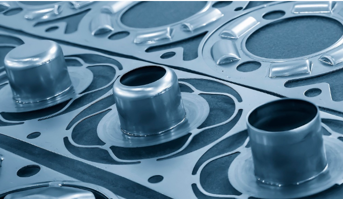
Представьте, что простая металлическая лента превращается в готовую, точно спроектированную деталь без единого извлечения её из пресса. Именно это и обеспечивает прогрессивная формовка — и она меняет подход производителей к серийному производству .
В отличие от одностанционной штамповки, при которой каждая операция требует отдельной настройки, прогрессивная штамповка с использованием многопозиционных штампов объединяет несколько операций формовки в одну непрерывную автоматизированную последовательность. Результат? Значительно более короткое время цикла, исключительная стабильность параметров и существенное снижение себестоимости одной детали при объёмах, оправдывающих инвестиции в оснастку.
Прогрессивная формовка — это процесс обработки металла, при котором металлическая лента подаётся с рулона через единый прецизионный штамп, а каждый ход пресса выполняет сразу несколько заранее спроектированных операций — резку, гибку, вытяжку и формовку — на последовательных станциях, обеспечивая автоматическое и непрерывное получение готовых деталей.
Как поэтапная формовка трансформирует производство изделий из листового металла
Вот где всё становится интересно. При традиционной штамповке вы, по сути, используете отдельные рабочие станции: на одной станции выполняется вырезание контура детали, на другой — гибка, на третьей — пробивка отверстий. Каждый этап требует отдельного инструмента, отдельной наладки и зачастую ручного перемещения заготовки между операциями. Поэтапная штамповка металла устраняет всё это трение.
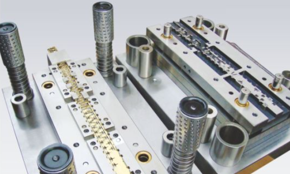
При поэтапной штамповке с использованием многопозиционного штампа металлическая лента входит в одну сторону штампа и выходит в виде готовой детали с другой стороны. Каждый ход пресса продвигает материал к следующей позиции, одновременно выполняя технологические операции на всех позициях последовательно. Один оператор может контролировать выпуск сотен — а иногда и тысяч — деталей в час.
Этот подход кардинально меняет экономику производства. Хотя первоначальные затраты на изготовление штампов выше, чем при использовании инструментов для одностадийных операций, резкое сокращение трудозатрат, времени на транспортировку и запасов незавершённого производства обеспечивает привлекательную отдачу при объёмах выпуска, превышающих определённые пороговые значения.
Принцип последовательных станций: пояснение
Так каким же образом материал фактически перемещается в ходе этого процесса? Секрет заключается в механизме непрерывной подачи ленты. Тяжёлая катушка металла поступает с разматывателя, проходит через выправляющее устройство для устранения внутренних напряжений, а затем подаётся в штамп с помощью прецизионного сервоподатчика. Этот податчик контролирует точное расстояние — так называемый шаг — на которое лента продвигается при каждом ходе пресса.
Надежность прогрессивной штамповочной технологии обеспечивается системой направляющих отверстий. На первых станциях в ленте пробиваются точные ориентировочные отверстия. Эти отверстия не входят в состав готовой детали — они выполняют функцию навигационной системы. При каждом ходе закрытия штампа конические направляющие пальцы входят в эти отверстия до начала любых операций формообразования, обеспечивая идеальное позиционирование ленты и устраняя накопительные погрешности установки.
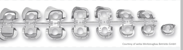
Лента остается соединенной с несущей полосой до последней станции отрезки, одновременно выполняя функции транспортера, приспособления и несущего каркаса на протяжении всей последовательности формообразования. Именно поэтому детали, полученные методом прогрессивной штамповки, отличаются столь выдающейся стабильностью: взаимное расположение каждого изгибов, отверстий и других элементов остается строго контролируемым от начала до конца.
Для инженеров, оценивающих методы производства, понимание этого последовательного принципа объясняет, почему прогрессивная штамповка стала предпочтительным решением для сложного массового производства в автомобильной, электронной и потребительской отраслях.
Полный поэтапный разбор процесса
Теперь, когда вы поняли базовые принципы, давайте подробно рассмотрим, что именно происходит на каждой станции в процессе прогрессивной штамповки. Именно здесь большинство пояснений оказываются недостаточными — они упоминают «множество операций», не раскрывая при этом точную последовательность, которая преобразует плоский металл в готовые детали .
Представьте штамп в прогрессивной штамповке как тщательно отрепетированную сборочную линию, сжатую в единый инструмент. Каждая станция выполняет одну конкретную задачу, а совокупный эффект обеспечивает получение деталей, для изготовления которых в противном случае потребовались бы несколько отдельных операций, обширное ручное вмешательство и значительные риски потери качества.
От рулона до готовой детали за один цикл прессования
Прежде чем переходить к рассмотрению отдельных станций, представьте себе весь процесс в целом. Рулон металлической ленты — порой весом в несколько тысяч фунтов — размещён на разматывателе, расположенном за прессом. Материал проходит через выправляющее устройство, устраняющее естественную кривизну рулона, а затем подаётся в штамп с точно выверенными интервалами. При каждом ходе пресса лента продвигается вперёд ровно на одну шаговую длину, в то время как штампы выполняют свои назначенные операции одновременно на каждой станции.
В чём преимущество этой системы? Пока на первой станции пробиваются направляющие отверстия в новом материале, на пятой станции может формироваться сложный изгиб, а на десятой — отделяться готовая деталь. Каждый ход пресса даёт законченную комплектующую — именно такая эффективность делает прогрессивную штамповку предпочтительным методом для массового производства.
Понимание работы каждой станции в прогрессивной последовательности
Процесс прогрессивной штамповки следует логической последовательности от простых к сложным операциям. Ниже приведена типичная последовательность станций, с которой вы столкнётесь в большинстве применений прогрессивных пробойников:
- Пробивка направляющих отверстий: На первой станции в ленте создаются прецизионные отверстия для точного позиционирования. Эти отверстия не являются функциональными элементами детали — они служат системой отсчёта, гарантирующей, что каждая последующая операция будет выполняться строго в заданном месте. Конические направляющие штифты входят в эти отверстия при каждом ходе, устраняя незначительные неточности подачи ленты до начала формообразования.
- Операции вырубки: Этот этап предусматривает удаление материала для формирования базового контура детали. Станции вырубки удаляют крупные участки ленты, создавая приблизительный внешний профиль. В некоторых конструкциях эта операция выполняется поэтапно, чтобы контролировать возникающие усилия и продлить срок службы штампа.
- Пробивка и вырезка выемок: Далее идут особенности интерьера. Пробойные станции пробивают отверстия, прорези и внутренние вырезы, определяющие функциональную геометрию детали. Операции вырубки удаляют материал с кромок для получения заданных профилей. Последовательность имеет значение: пробой выполняется до формовки, чтобы избежать деформации.
- Станции формования: Здесь плоский металл приобретает трёхмерную форму. Операции формовки создают изгибы, каналы и сложные формы за счёт контролируемого течения материала. Конструкция несущей ленты (сплошная или с растяжимыми перемычками) напрямую влияет на степень гибкости формовки на этих станциях.
- Операции гибки: Станции гибки создают угловые элементы — фланцы, ушки, кронштейны и конструктивные изгибы. В отличие от формовки, гибка обеспечивает чёткие углы вдоль заданных линий. Прогрессивные штампы часто включают несколько станций гибки, каждая из которых добавляет постепенные углы, предотвращая образование трещин или упругое восстановление формы.
- Калибровка и подгонка: Для деталей, требующих высокой точности размеров, операции клеймения выполняются на станциях клеймения с применением интенсивного локализованного давления для достижения заданных точных размеров, параметров шероховатости поверхности или толщины. Эта повторная штамповка обеспечивает соответствие критически важных элементов строгим требованиям — зачастую с допуском ±0,01 мм.
- Отрезка и выброс: На последней станции готовая деталь отделяется от ленточного носителя. Штампованный компонент выходит из пресс-формы по гравитационным желобам, с помощью воздушного выброса или механического извлечения, в то время как скелетный обрезок продолжает движение по линии для последующей переработки. Один цикл производства завершён — а следующая деталь уже сформирована и ожидает выхода.
Мощность данной последовательности заключается в её одновременности. Пока вы читаете о седьмой станции, имейте в виду, что станции с первой по шестую одновременно выполняют свои операции над последующими деталями при каждом ходе пресса. Пресс-форма, работающая со скоростью 200 ходов в минуту, производит 200 готовых деталей за ту же минуту — вне зависимости от количества станций в этой пресс-форме.
Точность этого процесса полностью зависит от упомянутой ранее системы направляющих отверстий. По мере опускания верхней матрицы направляющие штифты входят в установочные отверстия до того, как соприкоснутся с ними режущие или формовочные инструменты. Их конические поверхности создают боковые силы, которые смещают полосу в идеальное положение, восстанавливая его с каждым циклом. Такой подход «корректировка на каждом ходе» предотвращает накопление ошибок, которое в противном случае сделало бы невозможным использование матриц с большим количеством станций.
Понимание этих постанционных механических процессов объясняет, почему для штамповочных матриц требуется столь тщательное проектирование. Каждая операция должна учитывать поведение материала, распределение усилий и суммарное влияние всех предшествующих станций. При правильной проработке этой последовательности вы получаете высокопроизводительную производственную систему. Упустите критически важную деталь — и вам придётся выполнять дорогостоящие доработки матрицы ещё до получения одобрения первого образца.
После того как основа этого процесса заложена, следующим логическим вопросом становится: когда применение прогрессивной штамповки целесообразно по сравнению с другими методами? Ответ в значительной степени зависит от геометрии детали, объёмов производства и характеристик материала, которые мы подробно рассмотрим.
Сравнение методов прогрессивной, трансферной и компаундной штамповки
Вы уже ознакомились с тем, как работает прогрессивная штамповка поэтапно — но вот вопрос, имеющий решающее значение: является ли она действительно оптимальным выбором для вашего конкретного применения? Честный ответ зависит от ряда факторов, на которые многие инженеры не обращают внимания до тех пор, пока не будут уже выделены значительные средства на дорогостоящее изготовление оснастки.
Прогрессивная штамповка не является универсально превосходящей. Как и трансферная штамповка или компаундная штамповка . Каждый из этих методов демонстрирует наилучшие результаты в определённых условиях, и выбор неподходящего подхода может обойтись вам в десятки тысяч долларов из-за избыточных затрат на оснастку или неэффективного производства. Давайте подробно разберём, в каких именно случаях каждый из этих методов оказывается наиболее целесообразным.
Когда прогрессивная штамповка предпочтительнее трансферной и компаундной
Прогрессивная штамповка доминирует, когда выполняются три условия: высокие объёмы производства, умеренная сложность детали и совместимость с непрерывной лентой. Если ваш годовой спрос превышает 100 000 штук, а геометрия детали позволяет ей оставаться прикреплённой к несущей ленте на протяжении всего процесса формовки, использование прогрессивных штампов и штамповки становится чрезвычайно экономически эффективным.
Преимущество в скорости существенно. Прогрессивные штампы обычно работают со скоростью 200–400 ходов в минуту, а в некоторых высокоскоростных применениях достигают более 1000 ходов в минуту. Каждый ход производит готовую деталь. Сравните это с трансферной штамповкой, где механическая передача заготовки между станциями ограничивает практическую скорость до 30–60 ходов в минуту для сложных деталей.
Однако именно здесь штамповка с помощью переходной матрицы выходит на первое место: крупные, глубоковытяжные или трехмерно сложные детали, которые просто не могут оставаться прикрепленными к ленточному держателю. Когда для вашей детали требуется значительное перемещение материала — например, панели кузова автомобиля, глубокие чашки или детали, требующие доступа под углом 360° для операций формовки — штамповка с помощью переходной матрицы становится единственным жизнеспособным вариантом.
Штамповка компаундной матрицей занимает совершенно иную нишу. Этот метод выполняет несколько операций резки за один ход, обеспечивая изготовление плоских деталей с исключительной точностью. Если вам требуются простые вырубленные детали с жесткими допусками — шайбы, электрические контакты или плоские кронштейны — компаундные матрицы обеспечивают превосходную точность при более низких затратах на оснастку по сравнению с прогрессивными альтернативами.
Сопоставление геометрии детали с подходящим методом формовки
Геометрия детали зачастую определяет выбор метода ещё до того, как вы начнёте учитывать объёмы производства. Задайте себе следующие вопросы:
- Может ли деталь оставаться на ленточном держателе? Если да, то возможна постепенная штамповка. Если для штамповки детали требуется ее полное отделение для обеспечения доступа, рассмотрите возможность использования переносной штамповки.
- Остается ли деталь относительно плоской? Комбинированные штампы отлично подходят для изготовления точных плоских деталей. Постепенная и переносная штамповка позволяют выполнять объемную (трехмерную) штамповку.
- Каков максимальный размер детали? Постепенные штампы обычно подходят для деталей размером до 12–18 дюймов. Для более крупных компонентов предпочтительнее переносная штамповка на прессах.
- Сколько операций требуется? Простые детали с небольшим количеством операций могут не оправдывать сложности постепенной оснастки.
В приведенной ниже сравнительной таблице указаны объективные критерии для оценки каждого метода в соответствии с вашими конкретными требованиями:
| Критерии | Прогрессивная штамповка | Передача штамповки | Штамповка составными матрицами |
|---|---|---|---|
| Возможности по сложности детали | Умеренный — высокий; ограничен требованием к креплению заготовки на ленте | Очень высокий; позволяет выполнять глубокую вытяжку, обрабатывать крупногабаритные детали и сложные трехмерные геометрические формы | Низкий; оптимален для плоских деталей с несколькими вырезанными элементами |
| Идеальный объем производства | Высокий объём (100 000 и более ежегодно); себестоимость одной детали значительно снижается при увеличении объёма производства | Средний или высокий объём; универсален для различных объёмов выпуска | Низкий или средний объём; экономичен для простых производственных задач |
| Коэффициент использования материала | 70–85 % — типично; лента-носитель становится отходом | 80–90 %; индивидуальные заготовки минимизируют отходы | 85–95 %; отлично подходит для компоновки плоских деталей методом вложенной штамповки |
| Уровень инвестиций в оснастку | Высокие первоначальные затраты (от 50 000 до 500 000+ долларов США); окупаются за счёт объёма производства | Высокие (от 75 000 до 400 000+ долларов США); включают механизмы транспортировки | Ниже (от 15 000 до 100 000 долларов США); более простая конструкция штампа |
| Время цикла / Скорость производства | Очень высокая (200–1000+ ходов/минуту) | Умеренная (обычно 30–60 ходов/минуту) | Умеренная (60–150 ходов/минуту) |
| Время установки | Умеренная; установка одного штампа | Более длительная; требует калибровки системы перемещения | Короткая; простая центровка штампа |
| Требования к обслуживанию | Регулярное профилактическое обслуживание критически важно из-за сложности конструкции | Высокая; требуется внимание как к штампу, так и к механизмам перемещения | Низкая; более простая конструкция требует меньшего обслуживания |
Обратите внимание на компромиссы, заложенные в этом сравнении. При постепенной формовке несколько снижается коэффициент использования материала — несущая лента превращается в отходы — в обмен на беспрецедентную скорость производства. При переносной штамповке допускаются более медленные циклы работы для достижения возможностей формовки, недостижимых при методах с фиксацией заготовки на ленте. Комбинированные штампы жертвуют сложностью и функциональностью ради экономической эффективности и высокой точности при простых геометрических формах.
При оценке переносной штамповки для вашего применения учтите, что данный метод предполагает механическое или ручное перемещение отдельных деталей между станциями. Такой подход обеспечивает гибкость при обращении с деталями и их ориентации, которой прогрессивные методы просто не могут достичь. Для сложных конструкций, требующих выполнения операций с нескольких сторон, переносная штамповка на прессе зачастую становится единственным практически применимым решением.
Уравнение затрат кардинально меняется в зависимости от объёма. При годовом выпуске 10 000 деталей более низкие затраты на оснастку комбинированной матрицы могут обеспечить наилучшую совокупную стоимость, несмотря на более медленное производство. При выпуске 500 000 деталей преимущество прогрессивной штамповки в скорости производства перевешивает её более высокую стоимость оснастки — экономия на каждой детали быстро накапливается. Штамповка с использованием переходной матрицы обычно занимает промежуточное положение между этими крайностями и обеспечивает гибкость для производителей, чей ассортимент продукции варьируется или объёмы выпуска колеблются в зависимости от программ.
Один часто упускаемый из виду фактор — сложность технического обслуживания. Прогрессивные матрицы требуют регулярного профилактического обслуживания из-за своей сложной многостанционной конструкции. Переходные матрицы требуют внимания как к инструментам формообразования, так и к механическим системам перемещения. Комбинированные матрицы благодаря своей более простой конструкции, как правило, нуждаются в менее частом вмешательстве — хотя режущие кромки по-прежнему требуют контроля и заточки.
Выбор между этими методами — это не поиск «наилучшей» технологии, а подбор подходящего процесса с учётом конкретной геометрии детали, требуемых объёмов производства и ограничений по стоимости. Сформировав эту сравнительную основу, следующим важнейшим решением становится выбор материала и понимание того, как различные металлы ведут себя в условиях прогрессивной формовки.
Выбор правильных материалов для успешной прогрессивной формовки
Вы определили, что прогрессивная формовка соответствует вашим производственным требованиям — однако именно на этом этапе многие инженеры допускают ошибки: они выбирают материал, который выглядит превосходно в технической документации, но проявляет непредсказуемое поведение при высокоскоростной формовке. Разница между бесперебойной работой производственной линии и постоянным обслуживанием штампов зачастую определяется пониманием того, как конкретные металлы реагируют на уникальные требования прогрессивной стальдавильной штамповки.
Почему выбор материала имеет столь важное значение именно для прогрессивных операций? В отличие от штамповки на одностанционном прессе, где параметры можно корректировать между операциями, прогрессивные штампы требуют стабильного поведения материала на каждой станции и при каждом ходе — тысячи раз в час. Материал, который интенсивно упрочняется при пластической деформации, может прекрасно формоваться на третьей станции, но растрескаться на седьмой. Именно взаимодействие свойств материала и последовательных этапов формовки определяет успех программы или приводит к дорогостоящим неудачам.
Свойства материалов, определяющие успех прогрессивной формовки
Прежде чем рассматривать конкретные металлы, необходимо понять четыре свойства, определяющие поведение при формовке в любом применении штамповки металла:
- Пластичность и обрабатываемость: Формовка происходит при напряжениях, лежащих между пределом текучести и пределом прочности материала. Если напряжение не превышает предела текучести, формовка не происходит. Превышение предела прочности приводит к разрушению материала. У высокопрочных материалов интервал между пределом текучести и пределом прочности становится очень узким — оставляя минимальный запас прочности. Однородный размер зерна по всей длине полосы напрямую влияет на формоустойчивость, поэтому использование материала, полученного на прецизионных станках повторной прокатки, зачастую позволяет избежать проблем, возникающих при применении материалов товарного качества.
- Прочность на растяжение: Этот параметр характеризует величину растягивающей или вытягивающей силы, которую металл может выдержать до разрушения. При проектировании прогрессивных штамповочных операций необходимо сбалансировать требования к прочности готовой детали и требования к формовке на каждой операционной позиции. Более высокая прочность не всегда является преимуществом: чрезмерно высокий предел прочности снижает формоустойчивость и ускоряет износ штампов.
- Скорость упрочнения при деформации: По мере штамповки и формовки металла его кристаллическая структура изменяется. Материал становится твёрдее и хрупче с каждой операцией. Материалы с высокой скоростью упрочнения при деформации могут требовать отжига между отдельными этапами формовки — либо тщательного проектирования последовательности станций, чтобы предотвратить появление трещин на последующих операциях.
- Обрабатываемость: Легкость резания, обрезки и формовки материала влияет как на качество поверхности готовой детали, так и на срок службы штампа. Материалы с низкой обрабатываемостью образуют более грубые кромки, требуют более частой заточки инструмента и могут нуждаться в дополнительных отделочных операциях, что увеличивает себестоимость.
Эти свойства взаимодействуют сложным образом. Например, аустенитная нержавеющая сталь обладает высоким индексом холодного упрочнения и может претерпевать фазовые превращения при деформации, сопровождающиеся образованием хрупкой мартенситной фазы. Эта фаза проявляется тем сильнее, чем дальше продвигается процесс формовки, что приводит к росту остаточных напряжений и повышению риска образования трещин — именно такой накопительный эффект делает выбор материала для прогрессивной формовки чрезвычайно важным.
Диапазоны толщин и их влияние на проектирование штампов
Толщина материала напрямую влияет на конструкцию станции, силы формовки и достижимые допуски. Слишком малая толщина приводит к проблемам с деформацией и обработкой заготовки. Слишком большая толщина может привести к тому, что силы формовки превысят практические пределы или потребуется чрезмерное количество станций для достижения требуемых геометрических параметров.
В следующей таблице приведены оптимальные диапазоны толщин и характеристики формовки для распространённых материалов, используемых в прогрессивной штамповке:
| Материал | Оптимальный диапазон толщины | Характеристики формообразования | Лучшие применения |
|---|---|---|---|
| Углеродистая сталь | 0,4 мм – 6,0 мм | Отличная формоустойчивость; хорошо принимает покрытия; предсказуемое поведение при высокоскоростной оснастке; экономичность | Кронштейны, корпуса, конструкционные компоненты, колпачки для смазки |
| Нержавеющая сталь (серия 300) | 0,3 мм – 4,0 мм | Более выраженный упругий возврат; быстрая наклёпка; требует тщательного планирования последовательности изгибов; отличная коррозионная стойкость | Медицинские устройства, оборудование для пищевой промышленности, компоненты систем отопления, вентиляции и кондиционирования воздуха |
| Нержавеющая сталь (серия 400) | 0,3 мм – 3,5 мм | Магнитный; умеренная формоустойчивость; хорошая износостойкость; менее пластичен по сравнению с марками серии 300 | Режущие инструменты, пружины, применения с высоким износом |
| Алюминий | 0,5 мм – 5,0 мм | Высокое отношение прочности к массе; отличная формоустойчивость; склонен к залипанию без надлежащей подготовки матрицы; быстрая формовка | Электрические корпуса, аэрокосмические компоненты, товары повседневного спроса |
| Медь | 0.2мм - 3.0мм | Очень мягкий и пластичный; превосходная электропроводность; требует тщательного контроля радиусов изгиба; склонен к наклёпу | Электрические разъёмы, клеммы, компоненты для управления тепловыми процессами |
| Латунь | 0,3 мм – 4,0 мм | Гладкое формование; снижение износа инструмента; хорошая обрабатываемость; теплопроводность и электропроводность | Клапаны, шестерни, декоративные крепёжные элементы, прецизионные разъёмы |
| Бериллиевая бронза | 0,2 мм – 2,5 мм | Высокая устойчивость к механическим нагрузкам; неискрящийся; превосходная усталостная прочность; требует специальных мер при обращении | Пружины, детали авиационных двигателей, подшипники, работающие в условиях высоких нагрузок |
| Титан | 0,3 мм – 2,0 мм | Исключительное соотношение прочности к массе; коррозионная стойкость; сложность формования; требуются пониженные скорости обработки | Аэрокосмическая отрасль, медицинские импланты, военные и оборонные применения |
Обратите внимание, как диапазоны толщин значительно различаются в зависимости от материала. Широкий диапазон для углеродистой стали — от 0,4 мм до 6,0 мм — отражает её универсальные свойства при формовке и широкое применение в прогрессивных операциях. Более узкий диапазон для титана подчёркивает сложности, присущие формовке этого высокопрочного материала: его прочность требует более низких скоростей формовки и более постепенного продвижения заготовки по станциям.
В частности, для прогрессивной штамповки из углеродистой стали холоднокатаный материал обладает существенными преимуществами по сравнению с горячекатаными аналогами: более гладкая поверхность готовых изделий, чёткие кромки, стабильные геометрические размеры и повышенная прочность. Эти характеристики напрямую обеспечивают более предсказуемое поведение штампа и более строгие допуски на детали — именно то, что требуется при высокопроизводительных прогрессивных операциях.
Когда ваше применение требует повышенной коррозионной стойкости, но при этом необходимо сохранить экономическую эффективность углеродистой стали, рассмотрите возможность нанесения цинковых, хромовых или никелевых покрытий после штамповки. Многие производители штамповочных пресс-форм для листового металла координируют процесс гальванического покрытия через утверждённых поставщиков, поставляя полностью готовые детали без необходимости для заказчиков управлять взаимодействием с несколькими поставщиками.
Алюминий требует особого внимания при проектировании штамповочных пресс-форм для листового металла. Хотя он легко формуется и обеспечивает отличное качество поверхности, алюминий может вызывать заедание или оставлять следы без надлежащей подготовки рабочих поверхностей пресс-формы. В прогрессивных пресс-формах, предназначенных для обработки алюминия, часто применяются специализированные покрытия, системы смазки и методы обработки поверхностей, предотвращающие адгезию материала к инструментальным поверхностям.
В конечном счете, соответствие свойств материала конкретным требованиям к вашей детали — прочность, электропроводность, коррозионная стойкость, масса — определяет, какой из этих типов материалов для штамповочных матриц обеспечит оптимальные результаты. Технология штамповки существует для эффективной обработки всех этих материалов; вопрос заключается в том, учитывают ли ваш дизайн и технические требования к матрице уникальное поведение каждого материала при поэтапном формообразовании.
После определения принципов выбора материалов следующим важнейшим фактором становится проектирование самой матрицы — в частности, то, как современные CAD/CAM-системы и программное обеспечение для моделирования трансформировали инженерный процесс, превращающий эти соображения, связанные с материалами, в готовые к производству инструменты.
Принципы проектирования прогрессивных матриц и современные технологии изготовления оснастки
Вы выбрали материал, подтвердили, что прогрессивная штамповка соответствует вашим требованиям по объёму производства, и понимаете процесс поштационно. Теперь наступает этап, на котором успех производства либо закладывается в конструкцию штампа, либо дорогостоящие проблемы непреднамеренно проектируются в него. Проектирование прогрессивных штампов — это тот момент, когда теория сталкивается с реальностью, а современная интеграция CAD/CAM кардинально расширила возможности проектирования.
Вот что отличает выдающиеся прогрессивные штампы от посредственных: тщательное внимание к размещению заготовки на ленте, стратегии расположения направляющих отверстий, расстоянию между станциями и управлению отходами. Эти элементы взаимодействуют сложным образом, неочевидным на первый взгляд, и их правильная реализация требует как инженерной экспертизы, так и передовых программ моделирования. Рассмотрим каждый из ключевых элементов проектирования.
Оптимизация размещения заготовки на ленте для достижения максимального коэффициента использования материала
Расположение деталей на ленте — это расположение элементов в металлической ленте по мере её продвижения через штамп — напрямую влияет на стоимость материала, качество формовки и производственную эффективность. При плохо оптимизированном расположении до 30 % материала может быть потеряно в виде отходов. Экспертно разработанное расположение для той же детали может обеспечить коэффициент использования материала 85 % и выше.
При разработке расположения деталей на ленте инженеры решают сложную задачу: размещают каждый элемент, вырез, сформированный участок, сохраняя при этом достаточный объём несущего материала для надёжного перемещения ленты через все станции. Конструкция несущей части сама по себе предполагает компромиссы. Сплошные несущие части обеспечивают максимальную устойчивость, но ограничивают гибкость формовки. Растяжимые перемычки — узкие соединительные полосы между станциями — позволяют большее перемещение материала в процессе операций формовки, однако требуют тщательной инженерной проработки, чтобы предотвратить разрыв или деформацию.
Ключевые аспекты, которые следует учитывать при проектировании эффективного расположения деталей на ленте:
- Ориентация детали: Вращение деталей внутри ленты может значительно повысить эффективность размещения. Иногда поворот на 45 градусов устраняет отходы материала между соседними деталями.
- Ширина и положение несущей полосы: Несущая полоса должна быть достаточно широкой, чтобы выдерживать формовочные нагрузки без деформации, но при этом достаточно узкой для минимизации отходов. Центральные, боковые и двухполосные конструкции несущих полос подходят для разных геометрий деталей.
- Оптимизация шага: Расстояние между станциями влияет на расход материала, длину штампа и возможности формовки. Уменьшение шага снижает отходы материала, однако может не обеспечить достаточного пространства для выполнения сложных операций.
- Направление волокон: Ориентация критических изгибов перпендикулярно направлению волокон материала предотвращает появление трещин и улучшает качество сформированного края.
- Управление отходами в прогрессивном штампе: Проектирование места и способа удаления отходов влияет на сложность штампа и надёжность его работы. Накопление отходов вызывает заклинивание; чистое удаление отходов обеспечивает бесперебойную работу производства.
Согласно отраслевым методологиям проектирования, создание разводки заготовки является критически важным этапом, который определяет последовательность операций, оптимизирует расход материала, задаёт количество станций и устанавливает операции на каждом этапе. Этот этап планирования минимизирует отходы материала и обеспечивает эффективное производство на протяжении всего срока службы инструмента.
Ключевые компоненты штамповочного инструмента и их функции
Прогрессивные штампы объединяют десятки прецизионных компонентов, которые должны работать в полной гармонии. Понимание этих компонентов штампов для холодной штамповки помогает вам эффективно взаимодействовать со специалистами по изготовлению штампов и грамотно оценивать проектные предложения.
Конструкция штампа начинается с верхней и нижней плит — массивных стальных пластин, на которых крепятся все активные компоненты и которые обеспечивают жёсткость при высокоскоростных процессах формовки. Направляющие штифты и втулки обеспечивают точное взаимное расположение этих плит на протяжении всего хода пресса. Для прогрессивных штампов и матриц отраслевые стандарты обычно требуют наличия четырёх направляющих штифтов с направляющими на шарикоподшипниках, причём один из штифтов смещён для предотвращения неправильной сборки.
Особое внимание следует уделить направляющим отверстиям и направляющим штифтам. Как обсуждалось в предыдущих разделах, они не являются элементами детали — это система навигации. На первой операции пробиваются прецизионные установочные отверстия, а конические направляющие штифты входят в эти отверстия до начала любой операции формовки. Стандарты ведущих автопроизводителей (OEM) в области штампов устанавливают минимальный диаметр направляющих штифтов 10 мм, предпочтительно — 13 мм, и требуют применения направляющих штифтов с принудительным захватом (positive pick-up), а также наличия отверстий для удаления отходов (slug clearance holes), просверленных сквозь штамповую плиту.
Режущие стали, формовочные стали и пуансоны выполняют непосредственное преобразование материала. Для этих компонентов требуются определённые марки сталей в зависимости от операции: минимум инструментальная сталь марки A2 — для резки материалов толщиной 3,0 мм и менее; сталь марки S7 — для более толстых материалов; сталь марки D2 — для операций формовки и вытяжки. Покрытия, такие как Duplex Variantic, значительно увеличивают срок службы инструмента, особенно при обработке двухфазных материалов.
Один технический нюанс, который большинство источников упускают из виду: обходные вырезы (bypass notches). Эти небольшие элементы выполняют критически важную функцию в штамповой оснастке. Шаговые вырезы (pitch notches) — как правило, обрезаемые с одной или обеих сторон ленты — служат индикатором «первого удара» и обеспечивают точное позиционирование ленты. Стандарты отрасли требуют возможности обрезки шаговых вырезов минимум на 3 мм с одной стороны; обрезка с обеих сторон обязательна для лент толщиной менее 1,5 мм или шириной более 400 мм. Если лента не прилегает к шаговым вырезам при правильном ходе подачи, могут возникать накопительные погрешности позиционирования.
Интеграция CAE-моделирования в разработку штампов
Здесь современный прогрессивный дизайн штампов достиг значительных успехов. До того как CAE-моделирование стало повсеместно применяемым, инженеры полагались на свой опыт, пробные вырезы и дорогостоящие физические прототипы для проверки проектов. Сегодня программное обеспечение для моделирования предсказывает течение материала, выявляет потенциальные дефекты и оптимизирует параметры формовки ещё до того, как будет произведён первый разрез стали.
Многостадийное моделирование формовки стало обязательным требованием для крупных программ ОЕМ. Такие модели точно воспроизводят поведение материала при его перемещении через каждую станцию и позволяют выявить следующие проблемы:
- Волнистость: Сжатие материала, вызывающее неровности поверхности в отформованных областях
- Разрыв: Чрезмерное растяжение, превышающее пределы прочности материала и приводящее к образованию трещин
- Упругая деформация: Упругое восстановление после формовки, влияющее на конечные размеры детали
- Утончение стенки: Локальное уменьшение толщины материала в глубоковытяжных или сильно растянутых зонах
- Проблемы течения материала: Неправильное перемещение материала в процессе формовки, вызывающее деформацию или несоосность
Согласно передовым методам моделирования в CAE-системах, инженеры используют эту технологию для прогнозирования поведения материалов и выявления потенциальных проблем при штамповке до начала производства оснастки. Этот этап проверки помогает предотвратить дорогостоящие ошибки на стадии изготовления оснастки и её пробной отладки — ошибки, которые могут задержать реализацию проекта на недели и потребовать десятки тысяч долларов на устранение.
Программные платформы, такие как AutoForm-DieDesigner, напрямую интегрируются в рабочие процессы разработки прогрессивных штампов, позволяя инженерам проверять последовательности формообразования, оптимизировать конфигурации станций и обеспечивать соответствие деталей размерным требованиям до перехода к изготовлению физической оснастки. Эти инструменты кардинально изменили экономику разработки штампов: проблемы, которые ранее требовали нескольких итераций физической пробной отладки, теперь решаются в цифровой среде.
Сам процесс проверки проекта стал более строгим благодаря интеграции моделирования. Для основных программ теперь требуется многоступенчатое моделирование формовки до утверждения 50 % проекта, при этом все потенциальные режимы отказа должны быть устранены до перехода к окончательному проекту. Расположения обходных и штамповочных зон требуют утверждения до завершения 100 % проекта, что гарантирует проверку каждой детали на соответствие реальному поведению при формовке, а не предположениям.
Для производителей, оценивающих прогрессивные штампы, это означает необходимость задавать конкретные вопросы о методологии моделирования на этапе подготовки коммерческого предложения. Какое программное обеспечение использует изготовитель оснастки? Сколько итераций формовки было смоделировано? Были ли схемы течения материала проверены на соответствие реальным промышленным маркам материалов? Ответы на эти вопросы показывают, получаете ли вы глубокую инженерную проработку или просто копирование геометрии.
Современная разработка штамповочного инструмента объединяет моделирование в CAD, имитационное моделирование в CAE и планирование производства в единый непрерывный рабочий процесс. Раскладки ленты оптимизируют расход материала. Конструкции деталей задают точные допуски, материалы и виды термообработки. Имитационное моделирование подтверждает поведение заготовки при формовке. А подробные чертежи производства — полностью размерные 2D-чертежи и 3D-модели CAD — обеспечивают точное исполнение проекта изготовителями инструментов. Именно такой комплексный подход отличает готовые к серийному производству прогрессивные штампы от дорогостоящих экспериментов.
После освоения принципов проектирования и инструментов имитационного моделирования следующая задача заключается в сохранении этой точности на протяжении всего производственного цикла — в частности, в диагностике и устранении дефектов, неизбежно возникающих при формовке миллионов деталей в высокоскоростных прогрессивных операциях.
Устранение типичных дефектов при прогрессивной формовке
Ваша конструкция прогрессивного штампа прошла имитационное моделирование. Выбор материала соответствовал всем требованиям. Производство началось гладко — а затем возникли проблемы. Детали выходили скрученными, кромки имели неровные заусенцы или размеры выходили за пределы допусков. Знакомо? Эти проблемы вызывают раздражение даже у опытных инженеров, однако понимание их коренных причин позволяет перейти от реагирования на аварийные ситуации к системному решению проблем.
Дефекты при прогрессивной формовке редко имеют единственную причину. Они возникают в результате взаимодействия поведения материала, состояния штампа, параметров пресса и накопительных эффектов на нескольких станциях. То, что затрудняет диагностику — и что конкуренты систематически упускают из виду — это то, что симптомы, проявляющиеся на восьмой станции, могут иметь своё происхождение в условиях, существовавших на третьей станции. Давайте разработаем системный подход к диагностике и устранению наиболее распространённых дефектов.
Диагностика и устранение пружинения в формованных деталях
Упругое восстановление формы остается самой стойкой проблемой при точной штамповке с использованием пресс-форм. После отхода формующего пуансона собственная упругость металла вызывает частичное возвращение заготовки к исходной форме. Ваш изгиб под углом 90 градусов становится 87 градусов. Тщательно спроектированный радиус увеличивается. Размерные допуски, которые выглядели достижимыми при моделировании, на производстве становятся недостижимыми.
Почему возникает упругое восстановление формы? Согласно исследованиям в области штамповки металлов, на упругое отскакивание влияют несколько факторов: упругие свойства материала, сложность геометрии детали, уровень давления при штамповке и характеристики пресс-формы. Детали с выраженной кривизной, острыми углами или резкими изменениями формы особенно склонны к проявлению эффекта упругого восстановления формы.
Влияние этого явления выходит за рамки отдельных деталей. Упругое восстановление формы вызывает размерные погрешности, влияющие на точность сборки. Оно требует доработки деталей, что повышает себестоимость и задерживает поставки. Общая эффективность производства снижается, когда в ходе серийного выпуска приходится вносить коррективы.
Эффективные стратегии коррекции упругого отскока включают:
- Компенсация перегиба: Проектирование формовочных станций таким образом, чтобы изгиб выполнялся за пределы целевого угла, позволяя упругому отскоку привести деталь к конечным заданным параметрам. Для этого необходимо понимать характеристики упругого восстановления конкретного материала — обычно они определяются путём испытаний на изгиб образцов материала, соответствующего производственному.
- Оптимизации выбора материала: Некоторые материалы обладают меньшей упругостью и склонны к менее выраженному упругому отскоку. Когда критична размерная точность, выбор материалов с повышенной стойкостью к упругой деформации — даже при незначительно более высокой стоимости — зачастую оказывается экономически оправданным по сравнению с постоянными проблемами качества.
- Коррекция геометрии штампа: Компенсационные штампы противодействуют упругому отскоку за счёт контролируемой деформации материала при штамповке. Эти штампы имеют специальную геометрию, предназначенную для компенсации ожидаемого упругого восстановления, то есть фактически создают предварительное напряжение в материале.
- Операции выдавливания: Добавление станций калибровки, которые оказывают интенсивное локализованное давление, позволяет закрепить изгибы более надёжно. Пластическая деформация при калибровке снижает упругую составляющую, вызывающую отскок.
- Контроль температуры: Температура материала влияет на его упругое поведение. Регулировка температуры полосы перед формовкой — как за счёт контролируемого нагрева, так и за счёт обеспечения стабильных условий окружающей среды — позволяет снизить вариации отскока и повысить точность геометрических размеров.
Каждый случай требует проведения специфических испытаний и корректировок. Изгиб, который даёт отскок на 3 градуса в холоднокатаной стали, может дать отскок на 5 градусов в нержавеющей стали при идентичных условиях формовки. Документирование поведения материала при отскоке с разбивкой по марке стали, толщине и геометрии изгиба способствует формированию корпоративных знаний и ускоряет решение подобных задач в будущем.
Предотвращение образования заусенцев за счёт технического обслуживания штампов
Зачистки — неровные металлические выступы, остающиеся после операций резания — указывают на скрытые проблемы, которые усугубятся без вмешательства. Помимо ухудшения внешнего вида детали, зачистки нарушают точность сборки, создают угрозу безопасности и свидетельствуют об износе штампа, что ставит под угрозу размерную точность.
Понимание механизмов образования зачисток позволяет разработать стратегии их предотвращения. Согласно исследованиям в области прецизионного производства, зачистки возникают вследствие избыточного материала, остающегося после пластической деформации при резании. Основные причины можно разделить на три категории: неоптимальные параметры резания, проблемы с состоянием инструмента и особенности обрабатываемого материала.
Распространённые проблемы, связанные с зачистками, их причины и решения:
- Чрезмерная высота зачисток при пробивке отверстий: Обычно указывает на износ или скол режущих кромок. Тупая кромка не способна чисто отрезать металлические волокна, в результате материал разрывается вместо того, чтобы резаться. Решение: заточить режущие кромки пуансона и матрицы, соблюдая рекомендуемые проценты зазора для заданной толщины материала.
- Заусенцы только с одной стороны: Указывает на несоосность пуансона и матрицы. Неравномерный зазор приводит к чистому срезу с одной стороны и разрыву — с другой. Решение: проверьте и скорректируйте соосность пуансона и матрицы; осмотрите направляющие элементы на предмет износа.
- Увеличение образования заусенцев в течение производственного цикла: Постепенный износ режущей кромки при длительных циклах работы. Это нормальное явление при высокопроизводительном производстве, однако темпы нарастания указывают на целесообразность интервалов технического обслуживания. Решение: установите графики заточки в зависимости от типа обрабатываемого материала и объёма производства; фиксируйте количество ударов между техническими обслуживаниями.
- Образование заусенцев в материалах с высокой пластичностью: Алюминиевые и медные сплавы более склонны к пластической деформации и образованию заусенцев из-за своих физико-механических свойств. Решение: немного уменьшите зазоры при резании; обеспечьте остроту режущих кромок; рассмотрите возможность нанесения покрытий на пуансон для снижения адгезии.
Сама штамповочная машина способствует образованию заусенцев при неоптимальных условиях прессования. Избыточные скорости подачи увеличивают сжатие между инструментом и заготовкой, вызывая более значительную пластическую деформацию. Слишком низкие скорости резания приводят к «сдавливающему резанию» вместо плавного сдвига, что напрямую вызывает образование заусенцев.
Рекомендации по техническому обслуживанию штампов для обеспечения стабильного качества
Точное штампование требует постоянного внимания к состоянию инструмента — не только реагирования на возникновение проблем, когда они становятся очевидными. Согласно стандартам технического обслуживания прогрессивных штампов, эффективное обслуживание ориентировано на три основные цели: стабильность, документирование и непрерывное совершенствование.
Согласованность означает выявление, измерение и оценку каждой области инструмента, которая со временем будет ухудшаться. Две распространённые ошибки подрывают достижение этой цели: пропуск отдельных элементов износа и предположения о том, что определённые зоны износа не влияют на качество деталей. Эти ошибки приводят к нестабильному количеству ударов на один сервис и к колебаниям качества деталей, получаемых с помощью инструмента.
Документация даёт ответы на ключевые вопросы: сколько материала удаляется при заточке пуансона и матрицы? Какой полировальный материал сохраняет поверхности формующих вставок? Какие размеры требуют проверки и с какой точностью? При отсутствии документированных процедур каждый техник по обслуживанию выполняет техническое обслуживание по-своему, что создаёт вариации процесса и подрывает контроль качества.
Комплексный контрольный перечень технического обслуживания штамповочного пресса включает:
- Проверка режущего участка: Проверьте все режущие кромки на наличие следов износа; при необходимости выполните заточку, соблюдая заданные размеры уступа и угловую геометрию.
- Проверка направляющих отверстий: Проверьте все направляющие штифты на износ, уменьшение диаметра и состояние кончика; замените любые штифты, у которых обнаружен измеримый износ, поскольку точность направляющих штифтов влияет на каждую последующую операцию.
- Оценка формующего пуансона и матрицы: Проверьте все формующие компоненты на наличие износа поверхности, заедания или отклонения размеров; замените компоненты, у которых обнаружено любое измеримое отклонение от заданных параметров.
- Проверка пружин и подъёмников: Проверьте все пружины на соответствие требуемому усилию; осмотрите подъёмники на предмет износа и правильности работы; замените компоненты, проявляющие признаки усталости или нестабильного поведения.
- Проверка синхронизации: Проверьте последовательность синхронизации всех вставок, чтобы обеспечить выполнение операций в правильном порядке и с соблюдением корректных взаимосвязей.
Прогрессивные рисунки металлолома дают диагностическую информацию, которую опытные производители инструментов учатся читать. Устойчивые размеры лома указывают на стабильное состояние штампа. Изменения размера или формы лома сигнализируют о возникновении проблем, часто раньше, чем эти проблемы затрагивают готовые детали. Сбор и исследование образцов лома во время производственных работ позволяет заранее предупредить о возникновении проблем.
Постоянное совершенствование основывается на последовательном, документированном обслуживании. Какие изменения улучшат прочность инструмента? Какие компоненты наиболее разнообразны и могут воспользоваться улучшенными материалами или покрытиями? Могут ли различные сорта стали или карбида увеличить количество ударов в каждом отделе? Эти вопросы приводят к постоянной оптимизации, которая отделяет операции по штампованию металлов мирового класса от просто адекватных.
Инвестиции в систематическое техническое обслуживание приносят выгоду, выходящую за рамки предотвращения дефектов. Правильно обслуживаемые штампы работают быстрее и с меньшим простоем. Они производят детали с более высокой точностью геометрических размеров. Срок их службы увеличивается, что позволяет распределить затраты на оснастку на большее количество выпускаемых изделий. Для производителей, ориентированных на высокое качество штамповки по прецизионным штампам, техническое обслуживание — это не накладные расходы, а конкурентное преимущество.
После усвоения основных принципов диагностики следующим важным вопросом становится то, как эти принципы качества применяются в самых сложных условиях производства — в автомобильной промышленности, где требования автопроизводителей (OEM), стандарты сертификации и объёмы выпуска выводят возможности прогрессивной штамповки на предел.
Автомобильные применения и требования автопроизводителей (OEM) к качеству
Когда графики производства сжимаются, а допуски сокращаются до сотых долей миллиметра, автопроизводители не могут позволить себе никакой изменчивости. Именно поэтому прогрессивная штамповка автомобильных компонентов стала основой производства транспортных средств — обеспечивая требуемую производителями оригинального оборудования (OEM) стабильность, объём и точность.
Подумайте о том, что на самом деле находится внутри современного автомобиля. Тысячи металлических деталей — кронштейны для крепления жгутов проводов, разъёмы для соединения электронных систем, силовые элементы, распределяющие нагрузку при ударе, — должны безотказно функционировать на протяжении 150 000 миль и более. Каждая деталь подвергается воздействию вибрации, экстремальных температур, влажности и постоянных механических нагрузок. Прогрессивная формовка обеспечивает изготовление таких деталей с необходимой стабильностью геометрических размеров и воспроизводимостью, предъявляемыми требованиями автомобильной отрасли.
Соблюдение стандартов автомобильных OEM посредством прогрессивной формовки
Автопроизводители (OEM) не просто задают габаритные размеры деталей. Они определяют системы управления качеством, контроль технологических процессов, требования к документации и статистическую валидацию, гарантирующие соответствие каждой детали заданным спецификациям — не только выборочных образцов, но и каждой отдельной детали в рамках миллионов выпускаемых единиц.
Прогрессивно штампованные автомобильные детали отлично зарекомендовали себя в такой среде, поскольку сам процесс обеспечивает стабильность. После того как инженеры настраивают штамп, калибруют параметры подачи материала и проводят валидацию первых образцов, система выдаёт идентичные детали при каждом ходе пресса. Система выравнивания по направляющим отверстиям корректирует погрешности позиционирования на каждом цикле. Статистический контроль процесса в реальном времени отслеживает тенденции изменения геометрических параметров. При обнаружении отклонений операторы выявляют их до того, как бракованные детали попадут на сборочные линии.
Программы прогрессивной штамповки для автопроизводителей (OEM) обычно требуют:
- Документация PPAP: Документации по процедуре одобрения производственных деталей (PPAP), подтверждающей способность производственного процесса стабильно выпускать детали, полностью соответствующие всем техническим требованиям
- Статистическая способность процесса: Демонстрируемые значения Cpk 1,33 и выше для критических размеров, подтверждающие, что процесс центрирован в пределах допусков с запасом по отклонениям
- Системы прослеживаемости: Отслеживание партий материалов, кодирование даты производства и регистрация данных о качестве, связывающих каждую деталь с условиями её изготовления
- Программы непрерывного совершенствования: Документированные системы выявления и устранения источников вариаций со временем
Поступательные высокоточные штамповки из металла изначально соответствуют этим требованиям. Подход с последовательными станциями создаёт естественные точки контроля. Датчики, установленные непосредственно в штампе, позволяют проверять корректность выполнения операций. Автоматизированные системы машинного зрения контролируют критические параметры на скорости производства. В результате получается метод изготовления, спроектированный специально для интенсивного документирования и подтверждения соответствия, требуемого в автомобильной промышленности.
Сертификаты качества, имеющие значение при штамповке компонентов для автомобилей
Если вы закупаете компоненты, полученные методом прогрессивной штамповки, для автомобильных применений, одна сертификация имеет первостепенное значение: IATF 16949. Этот международно признанный стандарт специально регулирует систему менеджмента качества в автомобильной промышленности и представляет собой базовое требование к серьёзным поставщикам автокомпонентов.
Согласно документации по сертификации IATF, стандарт изначально был разработан Международной автомобильной рабочей группой (International Automotive Task Force) с целью унификации множества различных программ сертификации и систем оценки качества, используемых в мировой автомобильной промышленности. Его основные цели сосредоточены на предотвращении дефектов, снижении производственных отклонений и минимизации отходов — принципах, которые напрямую соответствуют врождённым возможностям прогрессивной штамповки.
Сертификация по стандарту IATF 16949 достигает трёх ключевых целей:
- Улучшение качества и согласованности: Рамочная структура сертификации повышает как качество продукции, так и стабильность производственных процессов, обеспечивая в качестве дополнительных преимуществ снижение производственных затрат и долгосрочную устойчивость
- Интеграция цепочек поставок: Благодаря проверенной последовательности и ответственности сертифицированные поставщики получают статус «поставщика выбора» у ведущих автопроизводителей, укрепляя и повышая надёжность отношений в цепочке поставок
- Интеграция стандартов: Требования IATF 16949 бесшовно интегрируются со стандартами сертификации ISO, применяемыми в отрасли в целом, создавая комплексную систему обеспечения качества вместо конкурирующих систем
Для производителей, оценивающих партнёров по штамповке, сертификация по IATF свидетельствует не только о приверженности качеству. Она подчёркивает ориентацию на клиента в производственном процессе — повышенное внимание к уникальным производственным потребностям, ожиданиям, требованиям и проблемам заказчика. Такая оперативность особенно важна при возникновении инженерных изменений в ходе реализации проекта или при непредвиденных колебаниях объёмов производства.
Сертификация также естественным образом распространяется на смежные отрасли высокой точности. Например, медицинская прогрессивная штамповка имеет много общих требований к системам управления качеством с автомобильными применениями — прослеживаемость, валидация процессов, документированные процедуры и статистический контроль. Поставщики, обслуживающие автомобильный рынок, зачастую обнаруживают, что их системы качества напрямую применимы в производстве медицинских изделий, где нормативные требования столь же строги.
Типичные автомобильные применения прогрессивной штамповки
Круг автомобильных применений прогрессивной формовки продолжает расширяться по мере усложнения конструкции транспортных средств. Компоненты, которые ранее изготавливались с использованием альтернативных методов производства, всё чаще переходят на прогрессивную штамповку, поскольку автопроизводители стремятся к обеспечению стабильности качества, снижению затрат и упрощению цепочки поставок.
Типичные автомобильные применения включают:
- Конструктивных кронштейнов и усиливающих элементов: Компоненты, распределяющие нагрузки по всей конструкции транспортного средства и требующие точной геометрии и стабильных свойств материала
- Электрические соединители и терминалы: Точные контакты, обеспечивающие надежные электрические соединения во всей проводке транспортного средства — часто изготавливаются из меди или латунных сплавов
- Корпуса датчиков и крепёжные элементы: Компоненты, обеспечивающие точное позиционирование датчиков в моторных отсеках, системах шасси и оборудовании безопасности
- Элементы каркаса сиденья: Зажимы, кронштейны и механизмы регулировки, требующие высокой прочности и точности размеров
- Комплектующие для систем отопления, вентиляции и кондиционирования воздуха (HVAC): Соединители воздуховодов, крепёжные кронштейны и компоненты управления потоком воздуха, работающие в условиях циклического изменения температуры
- Компоненты топливной системы: Кронштейны, зажимы и крепёжные элементы, соответствующие требованиям совместимости с топливом и стойкости к коррозии
Как отмечают эксперты отрасли, производители автомобильных компонентов полагаются на партнёров по массовому штампованию, способных соблюдать жёсткие графики поставок и строгие допуски. Прогрессивная штамповка особенно эффективна при изготовлении кронштейнов, зажимов, фиксаторов, разъёмов, корпусов и усиливающих элементов, которые должны выдерживать вибрацию, тепло и постоянные механические нагрузки.
Интеграция «Индустрии 4.0» в автомобильной штамповке
Современная прогрессивная штамповка в автомобилестроении всё чаще включает принципы интеллектуального производства. Вместо того чтобы рассматривать прессы как автономное оборудование, ведущие поставщики интегрируют системы реального времени для мониторинга, прогнозной аналитики и подключённых систем, повышающих качество и эффективность.
Практические примеры внедрения «Индустрии 4.0» в прогрессивной штамповке включают:
- Встроенные датчики в штамп Датчики контроля усилий формовки, положения ленты и наличия деталей на каждой станции — выявление аномалий до появления бракованных изделий
- Прогнозируемое обслуживание: Анализ вибрации и мониторинг тенденций для прогнозирования износа компонентов штампа до ухудшения качества, что позволяет проводить плановое техническое обслуживание вместо устранения неисправностей по факту
- Цифровые журналы качества: Автоматизированная документация, связывающая параметры производства с качеством деталей и обеспечивающая полную прослеживаемость без ручного ввода данных
- Статистический контроль процесса в реальном времени: Системы статистического контроля процесса (SPC), анализирующие размерные данные в ходе производственного цикла и сигнализирующие о возникающих тенденциях до выхода параметров за пределы допусков
Эти технологии трансформируют прогрессивную штамповку из производственного процесса в систему, генерирующую информацию. Данные о качестве автоматически поступают в порталы автопроизводителей (OEM). Графики технического обслуживания оптимизируются на основе реальных паттернов износа. Планирование производства интегрируется с сигналами спроса со стороны заказчиков. В результате формируется гибкая и прозрачная цепочка поставок, которую автопроизводители всё чаще ожидают от своих партнёров по штамповке.
Для производителей, рассматривающих решения по прогрессивной формовке для автомобильных применений, сотрудничество с Поставщиками, сертифицированными по стандарту IATF 16949 которые совмещают высокоточную оснастку с передовыми возможностями CAE-моделирования, гарантирует соответствие компонентов строгим требованиям автопроизводителей — от начального прототипирования до серийного массового производства.
После того как установлены требования к качеству и категории применения в автомобильной промышленности, следующим важнейшим аспектом становится финансовая сторона: понимание реальных затрат на инвестиции в прогрессивные штампы и определение момента, когда такие инвестиции обеспечивают привлекательную отдачу.
Анализ инвестиций и стратегии оптимизации затрат
Вы подтвердили, что прогрессивная штамповка соответствует вашим техническим требованиям. Теперь возникает вопрос, который зачастую определяет, будет ли проект реализован или застопорится на неопределённый срок: какова реальная стоимость и когда окупятся вложения? В отличие от более простых решений в области производства, экономика прогрессивной штамповки предполагает значительные первоначальные затраты на изготовление оснастки, которые компенсируются существенной экономией на каждой детали при крупносерийном производстве.
Что часто упускают из виду закупочные команды: сосредоточение исключительно на первоначальной смете игнорирует факторы, фактически определяющие долгосрочную рентабельность. Прогрессивная оснастка стоимостью 75 000 долларов США, производящая детали по 0,30 доллара США за штуку, даёт совершенно иную экономическую картину по сравнению с оснасткой стоимостью 40 000 долларов США, требующей частого технического обслуживания и производящей детали по 0,45 доллара США за штуку. Понимание полной картины затрат позволяет принимать обоснованные решения, а не дорогостоящие ошибки.
Расчёт истинной стоимости одной детали при прогрессивной штамповке
Уравнение стоимости на деталь при прогрессивной штамповке металла выходит далеко за рамки простого деления стоимости оснастки на объём производства. Согласно исследованию затрат на штамповку в автомобильной промышленности , на реальную экономическую эффективность производства влияет несколько взаимосвязанных факторов:
Сложность и конструкция детали: Это, пожалуй, самый значимый фактор, определяющий затраты. Простая плоская деталь, требующая лишь одной операции вырубки, нуждается в относительно недорогой матрице. Напротив, сложная автомобильная деталь с глубокими вытяжками, замысловатыми контурами и множеством пробивок требует высокоточной прогрессивной штамповочной матрицы. По оценкам отраслевых экспертов, каждая дополнительная станция в прогрессивной матрице может увеличить её общую стоимость на 8–12 %. Конструкторские решения, такие как острые углы или жёсткие допуски, требуют более прочной и точно обработанной оснастки, что дополнительно повышает цену.
Тип и толщина материала: Материал вашей конечной детали определяет требуемый материал штампа. Штамповка стандартной холоднокатаной стали предъявляет меньшие требования, чем формовка высокопрочного алюминия или сталей повышенной прочности (AHSS). Эти более твёрдые материалы вызывают больший износ и требуют применения более твёрдых и дорогих инструментальных сталей. Более толстые материалы требуют более прочных конструкций штампов и прессов с большей номинальной силой — оба фактора способствуют росту затрат на оснастку.
Объем производства и срок службы инструмента: Планируёмый объём производства напрямую влияет на проектирование штампа и выбор материала. Для небольших партий в несколько тысяч деталей может быть достаточным менее долговечный «мягкий инструмент». Однако для массового производства сотен тысяч или миллионов деталей требуется высококачественная, износостойкая инструментальная сталь, способная выдерживать длительную эксплуатацию. Хотя это повышает первоначальные капитальные затраты, в долгосрочной перспективе снижает себестоимость одной детали и минимизирует простои, связанные с техническим обслуживанием.
В следующей таблице представлены ключевые факторы стоимости и их влияние на общие инвестиции в прогрессивный штамп:
| Фактор стоимости | Низкое влияние сложности | Высокая сложность воздействия | Стратегия оптимизации |
|---|---|---|---|
| ## Количество станций | 3–5 станций: базовая стоимость | 10+ станций: повышение на 80–120 % | Комбинируйте операции там, где это возможно; исключите излишние функции |
| Марка материала для матрицы | Стандартная инструментальная сталь: базовая стоимость | Карбид / премиальные сплавы: повышение на 40–60 % | Подбирайте материал в соответствии с фактическими требованиями к объёму производства |
| Требования к допускам | Стандартные допуски: базовая стоимость | Повышенная точность допусков (±0,05 мм): повышение на 25–35 % | Указывайте строгие допуски только там, где это требуется функционально |
| Размер детали | Мелкие детали (< 100 мм): базовая стоимость | Крупные детали (> 300 мм): повышение стоимости на 50–100 % | Учитывайте ориентацию детали и оптимизацию размещения на листе |
| Ежегодное обслуживание | Простые штампы: 3–5 % от первоначальной стоимости | Сложные штампы: 8–12 % от первоначальной стоимости | Инвестируйте в качество на начальном этапе, чтобы снизить долгосрочные затраты на техническое обслуживание |
| Инженерное проектирование в CAD/CAE | Стандартный проект: 5 000–15 000 долларов США | Сложное моделирование: 25 000–50 000 долларов США | Инженерная проработка на ранних этапах для предотвращения дорогостоящих итераций при пробных запусках |
Согласно отраслевые методы оценки , не существует универсальной формулы для расчёта стоимости оснастки, однако можно учитывать множество факторов, повышающих точность оценки. Прогрессивные штампы, как правило, стоят дороже однопозиционных, поскольку требуют проектирования несущей ленты, последовательности подачи и подъёмников ленты, синхронизированных так, чтобы каждая позиция работала на одной и той же высоте.
Когда инвестиции в прогрессивный штамп экономически оправданы
Экономическая точка пересечения — при которой прогрессивная формовка становится более рентабельной по сравнению с альтернативными методами — зависит от конкретных объёмов производства и сложности детали. Понимание этого порогового значения позволяет избежать как преждевременных инвестиций в оснастку, так и упущенных возможностей снижения затрат.
На основе анализ точки безубыточности в производстве , расчёт основан на простом принципе: общая стоимость прогрессивной формовки (оснастка плюс детали) должна быть равной или ниже совокупной стоимости деталей, полученных альтернативными методами. Рассмотрите следующие ориентировочные значения:
- Менее 10 000 деталей: Альтернативные методы, такие как лазерная резка или штамповка простыми штампами, как правило, оказываются более экономичными. Затраты на оснастку не окупаются в достаточной степени при ограниченном объеме производства.
- 10 000–50 000 деталей: Переходная зона, в которой поэтапная формовка становится целесообразной в зависимости от сложности детали. Для более простых деталей по-прежнему могут быть предпочтительны альтернативные методы; для деталей со сложной геометрией преимущества поэтапной штамповки становятся всё более очевидными.
- более 50 000 деталей в год: Поэтапная штамповка металла обычно обеспечивает значительные экономические преимущества. Себестоимость одной детали резко снижается, одновременно повышаясь стабильность качества.
- более 100 000 деталей: Для подходящих геометрий поэтапная формовка становится бесспорным экономически обоснованным выбором. Затраты на оснастку становятся незначительными в расчёте на одну деталь.
Представьте, что вы сравниваете деталь, полученную лазерной резкой по цене 4,50 долл. США, с деталью, полученной штамповкой по цене 0,30 долл. США, при затратах на оснастку в 40 000 долл. США. Точка безубыточности достигается примерно на 9500-й детали — после этого каждая дополнительная деталь позволяет сэкономить 4,20 долл. США. При ежегодном объёме выпуска 100 000 деталей это даёт экономию в 420 000 долл. США в год по сравнению с единовременными затратами на оснастку.
Снижение рисков разработки за счет быстрого прототипирования
Вот где экономика прогрессивных штампов и оснастки становится особенно интересной: этап разработки зачастую определяет, будет ли проект успешным или превратится в дорогостоящий урок. Традиционные сроки изготовления оснастки, измеряемые месяцами, создают значительные риски — что, если дизайн потребует доработки после того, как вы уже инвестировали 100 000 долларов США в закалённую сталь?
Современные методы разработки прогрессивных штампов решают эту задачу за счёт интеграции прототипирования и имитационного моделирования. Современный инженерный анализ методом конечных элементов (CAE) выявляет потенциальные проблемы формовки ещё до того, как сталь будет обработана. Возможности быстрого прототипирования позволяют инженерам физически проверить работоспособность конструкции до начала изготовления производственной оснастки.
Ведущие производители штамповочных матриц теперь предлагают прототипирование с выполнением заказов всего за 5 дней — это лишь небольшая доля традиционных сроков разработки. Такая скорость принципиально меняет уравнение рисков. Вместо того чтобы принимать решение о запуске в производство на основе теоретического анализа, инженеры могут протестировать реальные штампованные детали, проверить их пригодность для сборки и подтвердить поведение материала до осуществления крупных инвестиций.
Финансовый эффект выходит за рамки предотвращения ошибок при выборе штамповой оснастки. Более короткие циклы разработки означают более быстрый выход на рынок. Продукты поступают к клиентам раньше. Генерация выручки начинается раньше. Конкурентные преимущества многократно возрастают, когда сроки разработки сокращаются с месяцев до недель.
Согласно отраслевым эталонным показателям, хорошо спроектированные программы штамповки с прогрессивными штампами обеспечивают коэффициент одобрения с первого прохода на уровне 93 % — то есть детали соответствуют техническим требованиям без необходимости внесения изменений в штамп. Сравните это с программами, которые торопливо запускаются в производство без достаточной инженерной проверки: в таких случаях циклы доработок могут привести к задержкам на несколько недель и затратам на переделку в десятки тысяч долларов.
Общая стоимость владения: за пределами первоначального коммерческого предложения
Выбор поставщика исключительно на основе самого низкого первоначального коммерческого предложения является распространённой ошибкой при закупках. Такая цена зачастую отражает лишь часть общей стоимости владения. Комплексная оценка затрат должна учитывать текущие расходы, расходы на техническое обслуживание, а также стратегическую ценность партнёров по производству, обладающих необходимыми компетенциями.
Согласно анализу штамповки автомобильных деталей, штампы могут требовать повторной заточки каждые 50 000–200 000 ходов, а ежегодные расходы на техническое обслуживание обычно составляют 5–10 % от первоначальной стоимости штампа. Более дешёвый и менее качественный штамп, требующий частого обслуживания, приводит к более высоким совокупным затратам и увеличению простоев в течение всего срока службы.
Дополнительные эксплуатационные расходы, подлежащие оценке, включают:
- Неповторяющиеся инженерные расходы (NRE): Первоначальные расходы на проектирование, имитационное моделирование и изготовление прототипов, возникающие однократно, но существенно влияющие на общую инвестицию
- Расходы на пробный запуск: Материалы, время работы пресса и инженерные трудозатраты, необходимые для проверки работоспособности штампа и утверждения первой партии изделий
- Доставка и логистика: Особенно актуально для крупных прогрессивных штампов, требующих специализированного обращения и транспортировки
- Запасные компоненты: Критически важные изнашиваемые компоненты, которые хранятся на складе для минимизации перерывов в производстве во время технического обслуживания
- Обучение и документация: Обучение операторов, процедуры технического обслуживания и техническая документация, обеспечивающие успешное долгосрочное производство
При оценке потенциальных поставщиков обращайте внимание не только на ценники, но и на их возможности. Хорошо оснащенное предприятие, предлагающее комплексные решения «под ключ» — проектирование, изготовление, испытания и документированные графики технического обслуживания — позволяет избежать непредвиденных расходов на последующих этапах. Например, Инженерная команда Shaoyi предлагает комплексные услуги — от CAE-моделирования и изготовления прототипов до серийного производства, обеспечивая учет долгосрочных показателей эксплуатации и требований к техническому обслуживанию уже на этапе первоначального проектирования. Их сертификат IATF 16949 и передовые возможности моделирования значительно снижают долгосрочные риски и затраты для производителей, рассматривающих решения на основе прогрессивных штампов.
Вопросы, раскрывающие истинную ценность поставщика
Прежде чем принимать решение об инвестициях в прогрессивный штамп, задайте потенциальным партнерам следующие revealing вопросы:
- Какой метод оценки вы используете — основанный на опыте и сходстве или аналитический/основанный на программном обеспечении?
- Какова ваша типичная доля первичных одобрений новых прогрессивных штампов?
- Как быстро вы можете поставить прототипные детали для проверки конструкции?
- Что входит в вашу стандартную программу технического обслуживания и каковы типичные ежегодные расходы?
- Предоставляете ли вы обучение и документацию для проведения технического обслуживания штампов силами собственного персонала?
- Что происходит, если после первоначальных испытаний потребуются изменения в конструкции?
Поставщик, уверенный в своих инженерных возможностях, даст чёткие и подробные ответы. Расплывчатые формулировки или нежелание обсуждать долгосрочные затраты зачастую указывают на проблемы, которые проявятся уже после подписания контрактов.
Решение об инвестициях в конечном счёте сводится к сопоставлению экономических преимуществ прогрессивной штамповки с вашими конкретными производственными требованиями. Для программ с высоким объёмом выпуска и стабильной конструкцией достигаются впечатляющие результаты. Продукция с меньшим объёмом выпуска или быстро изменяющаяся может выгоднее производиться альтернативными методами — по крайней мере до тех пор, пока конструкция не стабилизируется и объёмы выпуска не оправдают инвестиции в оснастку.
После определения структуры затрат и анализа рентабельности инвестиций окончательным этапом становится интеграция всех рассмотренных аспектов — механики процесса, выбора материалов, принципов проектирования, требований к качеству и экономических факторов — в практическую систему принятия решений для ваших конкретных задач.
Принятие правильного решения о применении прогрессивной штамповки для вашей задачи
Теперь вы изучили прогрессивную штамповку со всех сторон: механику процесса, поведение материалов, принципы проектирования штампов, стратегии устранения неполадок, требования к качеству и финансовый анализ. Однако знания без практического применения не создают ценности. Вопрос заключается в следующем: как объединить эти выводы в обоснованное решение для вашей конкретной задачи?
Ответ заключается в систематической оценке, а не в интуитивных суждениях. Слишком многие производители либо преждевременно инвестируют в дорогостоящую оснастку, либо избегают прогрессивной штамповки, хотя именно она могла бы обеспечить существенные преимущества. Давайте разработаем практическую систему, которая поможет вам принять верное решение.
Ваш чек-лист для принятия решения о прогрессивной формовке
Прежде чем обращаться к поставщикам или запрашивать коммерческие предложения, внимательно проанализируйте следующие критерии оценки. Каждый из этих факторов влияет на то, является ли прогрессивная штамповка оптимальным производственным методом для вашей задачи — или же следует рассмотреть альтернативные технологии.
- Оценка объёма производства: Будет ли годовой объём превышать 50 000 деталей? Экономическая эффективность прогрессивной формовки значительно возрастает при превышении этого порога. При объёме от 100 000 деталей и выше данный метод, как правило, становится безусловным выбором для соответствующих геометрий.
- Совместимость геометрии детали: Может ли ваша деталь оставаться соединённой с транспортной лентой на протяжении всех операций формовки? Если в конструкции требуется доступ под углом 360° или полное отделение детали для выполнения некоторых операций, то передаточная штамповка может оказаться более подходящим решением.
- Требования к размерным допускам: Какие уровни точности требуются для ваших критических характеристик? Прогрессивные штампы и штамповка отлично обеспечивают соблюдение допусков ±0,05 мм на постоянной основе, однако указание более жёстких допусков, чем это необходимо функционально, существенно увеличивает затраты на изготовление оснастки.
- Согласованность выбора материала: Будет ли ваша указанная форма материала вести себя предсказуемо при высокоскоростных прогрессивных условиях? Материалы с высокой скоростью упрочнения при деформации или узким окном формовки требуют тщательного проектирования последовательности операций на станциях и, возможно, увеличения их количества.
- Оценка стабильности конструкции: Завершена ли конструкция вашего изделия или вы ожидаете инженерные изменения? Модификации прогрессивных штампов обходятся значительно дороже, чем корректировки прототипной оснастки — проведите валидацию конструкции до начала разработки производственной оснастки.
- Требования к сертификации качества: Требуют ли ваши заказчики сертификации IATF 16949, AS9100 или аналогичные? Убедитесь, что потенциальные поставщики обладают соответствующими сертификатами до того, как вы вложите значительные инженерные ресурсы.
- Расчёт совокупной стоимости владения: Вы рассмотрели ли расходы на техническое обслуживание, запасные компоненты и требования к долгосрочной поддержке, выходящие за рамки первоначальной сметы на оснастку?
Работа по данному контрольному списку позволяет определить, соответствует ли ваше применение преимуществам прогрессивной штамповки. Ответ «да» по большинству критериев свидетельствует о том, что прогрессивная оснастка заслуживает серьёзного рассмотрения. Несколько ответов «нет» указывают на то, что альтернативные методы — такие как комбинированные штампы, переносная штамповка или даже лазерная резка при небольших объёмах — могут лучше удовлетворять ваши потребности.
Следующие шаги по внедрению решений с использованием прогрессивных штампов
После того как вы убедились, что прогрессивная штамповка соответствует вашим требованиям, путь её внедрения следует логической последовательности, минимизирующей риски и ускоряющей вывод продукции в производство.
Начните с проверки проекта: Прежде чем запрашивать коммерческие предложения на производство штамповой оснастки, проверьте свою конструкцию с помощью CAE-моделирования и изготовления физических прототипов. Этот этап — часто обходящийся в долю стоимости производства штамповой оснастки — позволяет выявить проблемы формовки, нарушения течения материала и трудности, связанные с обеспечением заданных размеров, которые в противном случае потребовали бы дорогостоящей доработки штампов. В качестве примера передовых практик штамповки ведущие производители достигают показателя утверждения деталей с первого раза выше 93 % за счёт ранней инженерной верификации.
Раннее привлечение квалифицированных партнёров: Опытные поставщики штамповой оснастки и штампов предоставляют обратную связь по вопросам проектирования с учётом технологичности, что позволяет улучшить вашу деталь ещё до начала изготовления оснастки. Поделитесь с потенциальными партнёрами своими требованиями, допусками и прогнозами объёмов выпуска. Их рекомендации зачастую выявляют возможности оптимизации — модификации элементов конструкции, позволяющие сократить количество операций, альтернативные материалы, повышающие формоустойчивость, или корректировку допусков, снижающую себестоимость без ущерба для функциональности.
Установите чёткие технические требования: Документируйте все требования до начала изготовления оснастки. В вашей спецификации на штамповку должны быть указаны марка материала и поставщик, допуски размеров с обозначениями геометрических допусков (GD&T), требования к шероховатости поверхности, а также ожидания в отношении документации по качеству. Неоднозначность на этом этапе приводит к спорам в дальнейшем.
Планируйте успех производства: Прогрессивная формовка обеспечивает максимальную ценность, когда производство проходит гладко в течение длительного времени. Обсудите с поставщиком оснастки графики технического обслуживания, наличие запасных компонентов на складе и оказание постоянной поддержки. Понимание этих долгосрочных требований позволяет избежать неожиданностей после начала производства.
Производители, добивающиеся успеха с помощью прогрессивной штамповки, рассматривают её как стратегическое решение на всём жизненном цикле — от первоначальной проверки концепции до многолетней оптимизации производства. Они понимают, что процесс поэтапной обработки, рассмотренный в данной статье, — это не просто метод изготовления. Это система, которая вознаграждает тщательное планирование, точное исполнение и постоянное внимание к качеству.
Независимо от того, производите ли вы автомобильные кронштейны, электронные разъёмы или компоненты потребительских товаров, принципы остаются неизменными: выбирайте метод, соответствующий вашим требованиям; проводите проверку перед окончательным принятием решения; сотрудничайте с квалифицированными поставщиками; соблюдайте дисциплину, необходимую для высокоточного массового производства. Соблюдение этих условий превращает прогрессивную штамповку не просто в один из вариантов производства, а в конкурентное преимущество.
Часто задаваемые вопросы о прогрессивной штамповке
1. Что такое прогрессивная штамповка?
Прогрессивная штамповка — это процесс обработки металла, при котором рулон металлической ленты подаётся через один прецизионный штамп, выполняя несколько заранее спроектированных операций — резку, гибку, вытяжку и формовку — на последовательных станциях при каждом ходе пресса. Лента остаётся соединённой с несущей полосой на всём протяжении процесса, обеспечивая автоматическое и непрерывное получение готовых деталей. Этот метод идеально подходит для массового производства свыше 100 000 деталей в год и обеспечивает исключительную стабильность размеров, а также значительно более низкую себестоимость одной детали по сравнению с одностанционными штамповочными методами.
2. В чём разница между прогрессивным и комбинированным штампом?
Прогрессивные штампы выполняют несколько операций последовательно по мере продвижения металлической ленты через станции при каждом ходе пресса, обрабатывая детали умеренной и высокой сложности, закреплённые на несущей ленте. Комбинированные штампы выполняют несколько операций резки одновременно за один ход, обеспечивая изготовление плоских деталей с исключительной точностью и при более низких затратах на оснастку. Прогрессивные штампы особенно эффективны при серийном производстве трёхмерных компонентов, тогда как комбинированные штампы оптимальны для изготовления простых вырубных деталей, таких как шайбы, электрические контакты или плоские кронштейны, требующие строгого соблюдения допусков.
3. Какие материалы наиболее подходят для прогрессивной формовки?
Углеродистая сталь (толщиной от 0,4 до 6,0 мм) обеспечивает превосходную формоустойчивость и экономичное производство кронштейнов и конструкционных компонентов. Нержавеющая сталь обеспечивает коррозионную стойкость, однако требует тщательного соблюдения последовательности гибки из-за повышенного упругого возврата. Алюминий легко формуется и обеспечивает отличное качество поверхности, однако для предотвращения заедания необходимо правильное условие штампов. Сплавы меди и латуни хорошо подходят для электрических разъёмов, тогда как титан и бериллиевая медь применяются в специализированных аэрокосмических и высоконагруженных областях применения. Выбор материала зависит от его пластичности, предела прочности при растяжении, скорости наклёпа и ваших конкретных требований к допускам.
4. Сколько стоит изготовление прогрессивного штампа?
Стоимость штамповочного инструмента для прогрессивной штамповки обычно составляет от 50 000 до 500 000 долларов США и более, в зависимости от сложности детали, количества станций, требований к материалу и допускам. Каждая дополнительная станция может увеличить стоимость на 8–12 %. Инвестиции становятся экономически оправданными при годовых объёмах производства свыше 50 000 деталей, а при объёмах свыше 100 000 деталей обеспечивается высокая рентабельность. Ежегодные затраты на техническое обслуживание составляют 5–10 % от первоначальной стоимости покупки. Сотрудничество с сертифицированными поставщиками, предлагающими быстрое прототипирование (всего за 5 дней) и достигающими коэффициента одобрения при первом проходе 93 %, существенно снижает риски разработки и совокупную стоимость владения.
5. Каковы причины типичных дефектов при прогрессивной штамповке?
Возврат в исходное положение происходит, когда упругость материала вызывает частичное восстановление формы обработанных деталей, что требует компенсации за счёт чрезмерного изгиба или операций калибровки. Образование заусенцев возникает из-за изношенных режущих кромок, несоосности пуансона и матрицы или неправильных зазоров — эти проблемы устраняются регулярной заточкой и техническим обслуживанием. Размерные несоответствия часто связаны с износом направляющих отверстий или нарушением соосности станций. Успешная диагностика требует понимания того, что признаки дефектов на последующих станциях могут быть вызваны операциями, выполненными ранее, поэтому систематическое обслуживание штампов и ведение документации являются обязательными условиями обеспечения стабильного качества при прецизионном производстве.