 Małe partie, wysokie standardy. Nasza usługa szybkiego prototypowania sprawia, że weryfikacja jest szybsza i łatwiejsza —

Obróbka skrawaniem w praktyce: 9 kluczowych punktów – od procesu po wybór partnera
Co naprawdę oznacza obróbka skrawaniem w nowoczesnej produkcji przemysłowej
Czy kiedykolwiek zastanawiałeś się, jak powstają skomplikowane elementy wewnątrz smartfona lub precyzyjne części silnika odrzutowego? Odpowiedź tkwi w obróbce – podstawowym procesie produkcyjnym, który kształtuje nasz współczesny świat. Czym więc właściwie jest obróbka? W swojej istocie obróbka to proces produkcyjny typu ubytkowego, w którym materiał jest systematycznie usuwany z stałego przedmiotu obrabianego w celu uzyskania określonych kształtów, wymiarów oraz jakości powierzchni.
Obróbka to kontrolowane usuwanie materiału z przedmiotu obrabianego przy użyciu narzędzi tnących w celu wytworzenia części o precyzyjnych wymiarach, ścisłych dopuszczalnych odchyłkach i wysokiej jakości powierzchni.
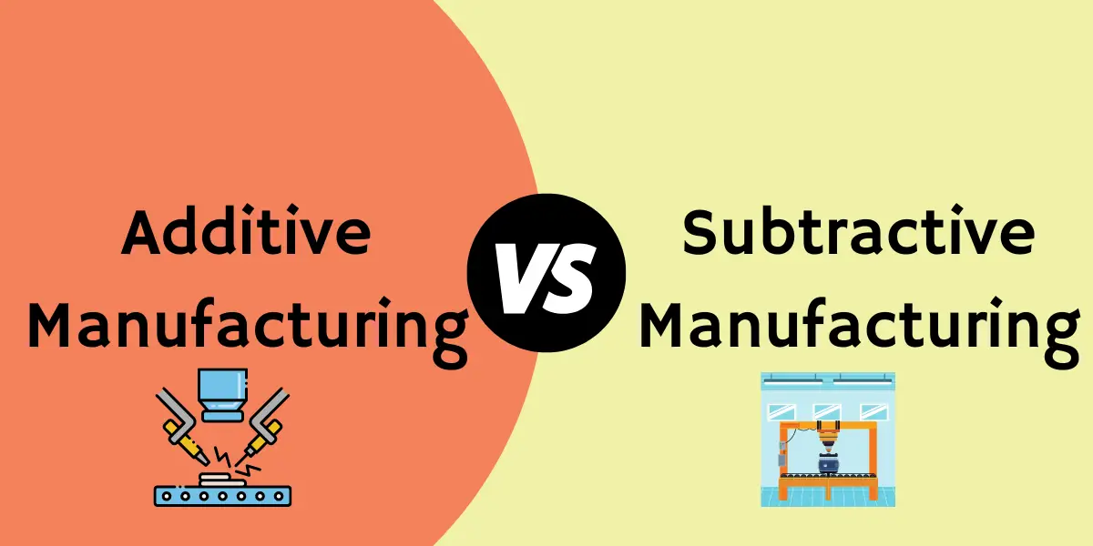
Ta definicja obróbki mechanicznej wyróżnia ją spośród innych podejść produkcyjnych, z jakimi możesz się spotkać. W przeciwieństwie do produkcji przyrostowej (powszechnie znanej jako druk 3D), która tworzy elementy warstwa po warstwie, obróbka mechaniczna zaczyna się od materiału o większych wymiarach niż wymagane i celowo usuwa nadmiar. Różni się również od procesów kształtujących, takich jak odlewanie lub kucie , w których materiał jest formowany za pomocą form lub ciśnienia bez istotnego jego usuwania.
Od surowca do precyzyjnego elementu
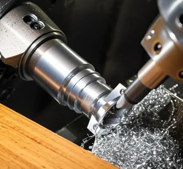
Wyobraź sobie, że zaczynasz od pełnego bloku aluminium lub stali. Dzięki precyzyjnie kontrolowanym operacjom skrawania ten surowy materiał przekształca się w złożony element o ścisłych specyfikacjach. To właśnie ten proces przekształcania nadaje obróbce mechanicznej jej wyjątkową uniwersalność. Niezależnie od tego, czy potrzebujesz jednego prototypu, czy tysięcy identycznych części, to podejście zapewnia spójne rezultaty.
Zasada obróbki ubytkowej
Definiując obróbkę skrawaniem, zasadnicze znaczenie ma zrozumienie zasady ubytkowej. Narzędzie tnące wchodzi w kontakt z przedmiotem obrabianym, usuwając cienkie warstwy materiału zwane wiórkami. Ta interakcja zachodzi w ściśle kontrolowanych warunkach — prędkość, posuw oraz głębokość skrawania współpracują ze sobą, aby osiągnąć pożądany efekt. Pojęcie obróbki skrawaniem wykracza poza proste usuwanie materiału; obejmuje ono cały system doboru narzędzi, możliwości maszyny oraz kontroli procesu.
Dlaczego usuwanie materiału ma znaczenie
Możesz zastanawiać się, dlaczego usuwanie materiału pozostaje tak istotne, skoro istnieją inne metody wytwarzania. Odpowiedź tkwi w nieosiągalnej precyzji i jakości powierzchni, jaką można uzyskać przy użyciu różnych typów obróbki skrawaniem. Rozważ poniższe zastosowania:
- Elementy konstrukcyjne do przemysłu lotniczego wymagające tolerancji rzędu tysięcznych cala
- Implanty medyczne wymagające powierzchni biokompatybilnych
- Części samochodowe wymagające spójnej jakości w milionach sztuk
- Obudowy urządzeń elektronicznych o złożonej geometrii
Od urządzenia w Twojej dłoni po samolot na niebie — komponenty wykonywane metodą obróbki skrawaniem są wszędzie. Ta powszechna ważność czyni zrozumienie różnych rodzajów obróbki skrawaniem niezbędnym dla inżynierów, projektantów oraz specjalistów ds. zakupów. W trakcie lektury tego przewodnika przejdziesz od podstawowych pojęć do praktycznych ram decyzyjnych – uzyskując umiejętności potrzebne do precyzyjnego określenia wymagań, oceny oraz pozyskiwania komponentów wykonywanych metodą obróbki skrawaniem z pełnym zaufaniem.
Podstawowe procesy obróbki skrawaniem, które powinien znać każdy inżynier
Teraz, gdy już wiesz, co oznacza obróbka skrawaniem, przejdźmy do konkretnych procesów, które ją umożliwiają. Każda operacja obróbkowa charakteryzuje się unikalnymi cechami, dzięki czemu jest szczególnie odpowiednia do określonych zastosowań. Wiedza na temat tego, kiedy należy użyć tokarki a kiedy frezarki – czy też kiedy specjalizowane metody, takie jak EDM stają się konieczne – pozwoli zaoszczędzić znaczne ilości czasu i środków finansowych w ramach Twojego kolejnego projektu.
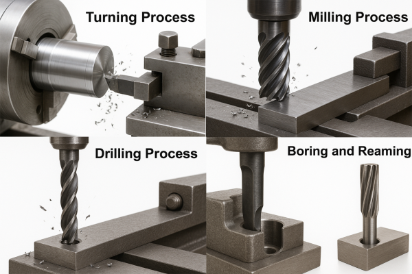
Wyjaśnienie toczenia i operacji tokarskich
Wyobraź sobie kawałek metalu wirujący z dużą prędkością, podczas gdy nieruchomy narzędzie do cięcia metalu stopniowo kształtuje jego powierzchnię. To właśnie tokarka w akcji. Tokarka obrotowa obraca przedmiot obrabiany względem narzędzia skrawającego, usuwając materiał w celu utworzenia kształtów cylindrycznych lub stożkowych. Proces ten doskonale nadaje się do produkcji wałów, sworzni, tulei oraz dowolnych elementów o symetrii obrotowej.
Tokarki występują w różnych konfiguracjach — od ręcznych tokarek uniwersalnych obsługiwanych przez wykwalifikowanych tokarzy po zaawansowane centra tokarskie CNC zdolne do wykonywania złożonych operacji wieloosiowych. Podstawowa zasada pozostaje niezmieniona: przedmiot obrabiany wiruje, a narzędzie porusza się wzdłuż zaprogramowanych ścieżek w celu uzyskania pożądanego kształtu geometrycznego. Typowe tolerancje dla precyzyjnego toczenia mieszczą się w zakresie od ±0,001 cala do ±0,0005 cala, w zależności od wyposażenia i materiału.
Frezowanie dla złożonych geometrii
A co jeśli Twój detal nie jest okrągły? Wtedy na pierwszy plan wychodzi frezowanie. W przeciwieństwie do tokarki, frezowanie wykorzystuje wirujący narzędzie skrawające, które porusza się po nieruchomym przedmiocie obrabianym. Ta wszechstronna metoda pozwala tworzyć powierzchnie płaskie, rowki, kieszenie oraz złożone kontury 3D, których niemożliwe jest uzyskanie na tokarce.
Współczesne frezarki obejmują od prostych pionowych frezarek 3-osiowych po zaawansowane centra frezarskie 5-osiowe. Dodatkowe osie pozwalają narzędziu skrawającemu zbliżyć się do przedmiotu obrabianego pod praktycznie dowolnym kątem, umożliwiając obróbkę złożonych elementów stosowanych w przemyśle lotniczym i urządzeń medycznych w jednej operacji montażowej. Operacje frezarskie obejmują:
- Frezowanie czołowe – Tworzenie powierzchni płaskich prostopadłych do osi wrzeciona
- Frezowaniu końcowym – Frezowanie rowków, kieszonek oraz profili o złożonym kształcie
- Frezowanie obwodowe – Obróbkę powierzchni równoległych do osi wrzeciona
- Wiercenie i rozwiercanie – Tworzenie otworów i ich dokładne rozszerzanie
Operacje wiercenia i szlifowania
Choć wiercenie może wydawać się proste — obracanie wiertełka w celu stworzenia otworów — to precyzyjne wiercenie wymaga starannego doboru prędkości obrotowych, posuwów oraz geometrii narzędzia. Specjalizowane odmiany, takie jak wiercenie głębokich otworów, wiercenie lufowe oraz rozwiercanie, pozwalają osiągać ścisłe допусki i doskonałą jakość powierzchni wewnątrz otworów.
Szlifowanie przesuwa poziom precyzji na jeszcze wyższy stopień. Zamiast ostrzy tnących stosuje się koła szlifierskie z materiałem ściernym, które usuwają niewielkie ilości materiału, umożliwiając uzyskanie powierzchni lustrzanej oraz dopuszczeń mierzonych w mikronach. Szlifowanie płaszczyzn, szlifowanie walcowe oraz szlifowanie bezosowe są przeznaczone do konkretnych zastosowań, w których tradycyjne narzędzia skrawające nie zapewniają wymaganej dokładności.
Specjalistycznych metod cięcia
Czasem tradycyjne operacje frezarskie czy tokarskie nie wystarczają. Zaawansowane metody służą do obróbki materiałów i kształtów, które stanowią wyzwanie dla konwencjonalnych podejść.
Machining za pomocą Wypalania Elektrycznego (EDM) wykorzystuje iskry elektryczne do erozji materiałów przewodzących prąd. W procesie drutowego EDM cienki drut elektrodowy jest przeprowadzany przez obrabiany przedmiot, osiągając dokładność rzędu ±2,5 µm – wyjątkową precyzję przy obróbce hartowanych stali narzędziowych i egzotycznych stopów, które szybko zniszczyłyby tradycyjne narzędzia skrawające. Jednak EDM działa wyłącznie na materiałach przewodzących prąd i charakteryzuje się stosunkowo niskimi prędkościami cięcia.
Wycinanie wodne przyspiesza cząstki ścierniowe w strumieniu wody pod wysokim ciśnieniem, skutecznie erozując materiał bez generowania ciepła. Mikrostrumieniowa technologia ścierna z wodą osiąga dokładność rzędu ok. ±10 µm przy prędkościach cięcia od 5 do 10 razy wyższych niż w przypadku EDM. Ten proces niegenerujący ciepła zachowuje właściwości materiału – szczególnie istotne przy obróbce stopów wrażliwych na ciepło oraz kompozytów.
Toczenie może wydawać się podstawowe, ale nowoczesne piły taśmowe i zimne piły zapewniają wydajne oddzielanie materiału przy minimalnych odpadach. W przypadku przygotowania prętów i wstępnego doboru ich wymiarów cięcie piłą pozostaje niezbędnym pierwszym krokiem w wielu procesach obróbki skrawaniem.
Porównanie procesów obróbki skrawaniem w pigułce
Wybór odpowiedniego procesu zależy od geometrii detalu, rodzaju materiału, wymaganych tolerancji oraz objętości produkcji. Poniższe porównanie pomoże w podjęciu tej decyzji:
| Proces | Rodzaj operacji | Typowe materiały | Osiągalne tolerancje | Jakość Powierzchni (Ra) | Najlepsze przypadki użycia |
|---|---|---|---|---|---|
| Toczenie (tokarka) | Obróbka obrotowa | Metale, tworzywa sztuczne, kompozyty | ±0,001 cala do ±0,0005 cala | 16–63 µin | Wały, sworznie, elementy cylindryczne |
| Wyroby z mięsa | Wieloosiowa obróbka skrawaniem | Metale, tworzywa sztuczne, kompozyty | ±0,001 cala do ±0,0002 cala | 32–125 µin | Złożone geometrie 3D, obudowy |
| Wiercenie | Tworzenie otworów | Najlepiej obrabialne materiały | ±0,002 cala do ±0,0005 cala | 63–250 µin | Otwory, otwory walcowane, elementy gwintowane |
| Szlifowanie | Wykańczanie ścierniowe | Utrudnione metale, ceramiki | ±0,0001 cala do ±0,00005 cala | 4–16 µcal | Powierzchnie precyzyjne, ścisłe допусki |
| Obróbka elektroerozyjna drutem | Erozja elektryczna | Tylko materiały przewodzące | ±0,0001" (±2,5 µm) | 8–32 µcal | Stale hartowane, złożone profile |
| Wodny strumień | Erozja ścierająca | Prawie wszystkie materiały | ±0,0004" (±10 µm) | 32–125 µin | Materiały wrażliwe na ciepło, kompozyty |
Wybór odpowiedniego procesu dla Twojej części
Jak dopasować wymagania dotyczące Twojej części do optymalnego procesu? Zacznij od następujących kwestii:
- Geometria Części – Części cylindryczne zwykle przetwarzane są na tokarkach; kształty graniaste – na frezarkach
- Właściwości materiału – Materiały hartowane mogą wymagać szlifowania lub elektroerozyjnego obróbki (EDM); kompozyty często nadają się do cięcia strumieniem wody (waterjet)
- Wymagania tolerancyjne – Wymagania ultra-dokładności mogą narzucać zastosowanie szlifowania lub końcowej obróbki elektroerozyjnej (EDM)
- Wolumen produkcji – Wysokie wolumeny produkcji sprzyjają zautomatyzowanym operacjom CNC; niskie wolumeny mogą wykorzystywać ręczne ustawienia
- Wymagania dotyczące chropowatości powierzchni – Dla powierzchni krytycznych może być konieczne dodatkowe szlifowanie lub polerowanie
Zrozumienie tych podstawowych operacji skrawania zapewnia Ci słownictwo umożliwiające skuteczną komunikację z warsztatami maszynowymi oraz podejmowanie świadomych decyzji dotyczących podejścia do produkcji. Jednak wybór między wyposażeniem ręcznym a sterowanym komputerowo wprowadza kolejny wymiar do rozważenia – temat, który omówimy w dalszej części.
Porównanie obróbki CNC i tradycyjnej
Zapoznałeś się z podstawowymi procesami — toczeniem, frezowaniem, szlifowaniem i innymi. Ale istnieje pytanie, które często decyduje o powodzeniu projektu: czy te operacje powinny być wykonywane na sprzęcie sterowanym komputerowo, czy też na tradycyjnych maszynach ręcznych? Odpowiedź nie zawsze jest oczywista, a zrozumienie kompromisów między obróbką CNC a konwencjonalną może zaoszczędzić znaczne ilości czasu i środków.
Rewolucja CNC w precyzyjnej obróbce
Sterowanie numeryczne komputerowe przekształciło produkcję poprzez zastąpienie kółek ręcznych i ręcznych regulacji precyzją cyfrową . Maszyna CNC odczytuje zaprogramowane instrukcje z oprogramowania CAD/CAM, automatycznie kontrolując ruch narzędzi wzdłuż wielu osi. Co to oznacza dla Twoich części? Powtarzalność mierzona w tysięcznych cala, skomplikowane geometrie realizowane w pojedynczym ustawieniu oraz spójna jakość – niezależnie od tego, czy produkujesz jedną część, czy tysiąc.
Precyzyjne frezowanie CNC doskonale ilustruje tę zaletę. Tam, gdzie operator ręczny może mieć trudności z powtarzaniem skomplikowanych konturów na wielu częściach, frezarka CNC wykonuje ten sam program identycznie za każdym razem. Jeden wykwalifikowany mechanik CNC może nadzorować jednocześnie kilka maszyn, z których każda wytwarza elementy spełniające ścisłe wymagania bez zmienności charakterystycznej dla operacji wykonywanych ręcznie.
Zalety te wykraczają poza samej precyzji:
- Zmniejszenie błędów ludzkich – Ruchy kontrolowane oprogramowaniem eliminują błędy wynikające z zmęczenia lub rozproszenia uwagi
- Wyższa wydajność – Maszyny pracują nieprzerwanie przy minimalnym nadzorze
- Złożone możliwości – Systemy wieloosiowe pozwalają tworzyć geometrie niemożliwe do osiągnięcia ręcznie
- Poprawione bezpieczeństwo – Operatorzy pracują za osłonami ochronnymi, w bezpiecznej odległości od poruszających się elementów
Gdy obróbka ręczna nadal ma przewagę
Skoro CNC oferuje takie zalety, to dlaczego maszyny ręczne nadal znajdują się w warsztatach na całym świecie? Odpowiedź tkwi w konkretnych sytuacjach, w których tradycyjne urządzenia okazują się bardziej praktyczne.
Wyobraź sobie, że potrzebujesz pojedynczego, niestandardowego uchwytu — czegoś szybkiego i prostego. Zaprogramowanie maszyny CNC, przygotowanie narzędzi oraz wykonanie próbnych cięć może zająć godziny, zanim wyprodukujesz tę jedną część. Doświadczony tokarz pracujący na urządzeniach ręcznych mógłby wykonać ten sam element w ułamku tego czasu. Co robią operatorzy obrabiarek w takich sytuacjach? Korzystają ze swoich umiejętności praktycznych, dostosowując parametry cięcia w czasie rzeczywistym na podstawie wizualnej informacji zwrotnej oraz wrażeń dotykowych.
Obróbka ręczna wyróżnia się w następujących przypadkach:
- Produkcja pojedynczych prototypów lub niestandardowych napraw
- Proste geometrie nie uzasadniają nakładu czasu na programowanie
- Ograniczenia budżetowe ograniczają inwestycje w sprzęt
- Szkolenie nowych operatorów obrabiarek w podstawowych technikach
Opis stanowiska doświadczonego operatora obrabiarki w środowisku ręcznym podkreśla rzemiosło — odczytywanie rysunków technicznych, dobór odpowiednich prędkości obrotowych i posuwów oraz dokonywanie mikro-korekt w trakcie procesu cięcia. Ta praktyczna wiedza pozostaje nadal wartościowa, szczególnie przy produkcji małych serii, gdzie czas przygotowania stanowi dominującą część całkowitego czasu produkcji.
Wybór poziomu automatyzacji
Decyzja między podejściem CNC a ręcznym zależy ostatecznie od konkretnych wymagań. Przyjrzyj się poniższemu porównaniu obok siebie:
| Czynnik | Obróbka CNC | Obróbka ręczna |
|---|---|---|
| Czas montażu | Dłuższe początkowe programowanie (godziny dla złożonych części) | Minimalne — można rozpocząć cięcie niemal natychmiast |
| Powtarzalność | Wysokie — identyczne części w każdej serii | Zmienne — zależy od spójności operatora |
| Wymagania dotyczące umiejętności operatora | Wymagana wiedza programistyczna; mniejsza potrzeba sprawności manualnej | Wysoka sprawność manualna; lata praktycznego doświadczenia |
| Koszt elementu (mała seria) | Wyższe — koszty przygotowania rozłożone na niewielką liczbę części | Niższe — szybkie przygotowanie, natychmiastowa produkcja |
| Koszt elementu (duża seria) | Niższe — automatyzacja zmniejsza koszty pracy przypadające na jednostkę | Wyższy — intensywnie wykorzystujący siłę roboczą na wszystkich etapach |
| Elastyczność w zakresie zmian projektowych | Umiarkowany — wymaga ponownego programowania | Wysoki — korekty wykonywane w locie |
| Osiągalna precyzja | ±0,0001 cala możliwe przy użyciu wysokiej klasy sprzętu | ±0,001 cala typowe przy zastosowaniu wykwalifikowanego operatora |
| Koszt usługi godzinowej | ~80 USD/godz. dla frezarek 3-osiowych (wyższy dla frezarek 5-osiowych) | ~40 USD/godz. |
Zwróć uwagę, jak ekonomia zmienia się wraz z wielkością serii. Dla serii produkcyjnej 500 części wyższy koszt przygotowania maszyny CNC staje się pomijalny po rozłożeniu na wszystkie jednostki, podczas gdy jej zautomatyzowana praca znacznie obniża koszt pracy przypadający na pojedynczą część. Dla trzech niestandardowych części obróbka ręczna często okazuje się bardziej opłacalna mimo niższej powtarzalności.
Współczesna rola mechanika
Kim jest tokarz w dzisiejszym środowisku produkcyjnym? Rola ta uległa znacznemu rozwojowi. Tradycyjni tokarze obsługiwali maszyny bezpośrednio — kręcili kółkami ręcznymi, odczytywali pomiary za pomocą mikrometrów i polegali na swoim doświadczeniu, aby osiągnąć wymagane tolerancje. Współczesni operatorzy CNC programują maszyny, monitorują cykle automatyczne oraz diagnozują i usuwają usterki w razie ich wystąpienia.
Wiele zakładów produkcyjnych przyjmuje obecnie podejście hybrydowe. Typowa warsztatowa hala obróbkowa może wykorzystywać tokarki ręczne do szybkiej produkcji prototypów, a jednocześnie stosować maszyny CNC do realizacji zamówień produkcyjnych. Doświadczeni tokarze swobodnie przechodzą między oboma typami maszyn, wykorzystując podstawową wiedzę z zakresu zasad skrawania – niezależnie od tego, czy ręcznie dostosowują parametry posuwu, czy optymalizują programy w kodzie G.
Ta ewolucja odzwierciedla szersze trendy branżowe. Firmy coraz częściej inwestują w możliwości obróbki CNC, zachowując przy tym sprzęt ręczny w celu zapewnienia elastyczności. Przejście to często odbywa się stopniowo — dodawanie mocy CNC do prac o wysokim wolumenie przy jednoczesnym utrzymywaniu maszyn konwencjonalnych do prototypowania i krótkich serii. Zrozumienie obu podejść pozwala ocenić potencjalnych partnerów produkcyjnych oraz określić odpowiednie rozwiązanie dla każdego projektu.
Gdy wybór procesu i poziom zautomatyzowania są już ustalone, pojawia się kolejny kluczowy czynnik: допuszczalne odchylenia wymiarowe oraz normy precyzji określające, czy Twoje elementy rzeczywiście działają zgodnie z przeznaczeniem.
Dopuszczalne odchylenia wymiarowe oraz normy precyzji określające jakość
Wybrałeś/aś swój proces i zdecydowałeś/aś się między wyposażeniem CNC a ręcznym. Ale istnieje pytanie, które ostatecznie decyduje o tym, czy wyprodukowane części rzeczywiście będą działać: czy proces produkcyjny pozwala na zachowanie wymaganych przez projekt tolerancji? Zrozumienie specyfikacji tolerancji pozwala odróżnić funkcjonalne elementy od drogiego odpadu — a brak tej wiedzy często zaskakuje inżynierów i zakupujących.
Zrozumienie specyfikacji tolerancji
Co dokładnie oznacza tolerancja w obróbce skrawaniem? Prościej mówiąc, jest to dopuszczalny zakres odchylenia wymiarowego od idealnej wartości określonej w dokumentacji technicznej. Żaden proces produkcyjny nie pozwala osiągnąć doskonałych wymiarów — tolerancje uwzględniają tę rzeczywistość, jednocześnie definiując dopuszczalne granice odchylenia. Gdy określisz średnicę otworu na 10,00 mm z tolerancją ±0,05 mm, informujesz zakład mechaniczny, że każda średnica w zakresie od 9,95 mm do 10,05 mm będzie poprawnie funkcjonować w Twoim zespole.
Tolerancje w precyzyjnej obróbce skrawaniem zwykle przyjmują standardowe formaty:
- Tolerancje dwustronne – Odchylenie dopuszczone w obu kierunkach (np. 10,00 ±0,05 mm)
- Tolerancje jednostronne – Wariantowość dopuszczalna tylko w jednym kierunku (np. 10,00 +0,00/−0,10 mm)
- Tolerancje graniczne – Wymiary górny i dolny podane bezpośrednio (np. 9,95–10,05 mm)
Dlaczego to ma znaczenie dla Twoich części obrabianych? Rozważmy precyzyjną część obrabianą, zaprojektowaną do montażu wciskowego w obudowie. Jeśli wał będzie nieco za gruby, a otwór nieco za ciasny, montaż stanie się niemożliwy. Z kolei nadmierna luzowość powoduje niepożądane przesunięcia. Specyfikacje tolerancji zapewniają spójność dopasowania we wszystkich tysiącach precyzyjnie obrabianych komponentów.
Standardowe tolerancje frezowania CNC zwykle mieszczą się w zakresie ±0,005 cala do ±0,030 cala przy pracach ogólnych. Obróbka wysokiej precyzji zawęża te limity – nawet do ±0,001 cala lub nawet ±0,0005 cala dla kluczowych cech geometrycznych. Wszelkie tolerancje poniżej ±0,001 cala należą do zakresu obróbki ultra-precyzyjnej, wymagającej specjalistycznego sprzętu i znacznie wyższych kosztów.
Poziomy precyzji w różnych branżach
Różne zastosowania wymagają zupełnie innych poziomów dokładności. To, co jest akceptowalne dla uchwytu konstrukcyjnego, spowodowałoby natychmiastowe odrzucenie części metalowych wykonanych metodą obróbki skrawaniem w urządzeniach medycznych. Zrozumienie tych oczekiwań pozwala określić odpowiednie допусki — wystarczająco ścisłe, aby zapewnić funkcjonalność, ale nie tak ścisłe, aby koszty nie rosły niepotrzebnie.
Oto typowy podział wymagań dotyczących dopuszczalnych odchyłek w zależności od zastosowania:
| Kategoria zastosowań | Typowy zakres tolerancji | Jakość Powierzchni (Ra) | Przykłady |
|---|---|---|---|
| Komercyjne / Ogólne | ±0,010" do ±0,030" | 63–125 µin | Uchwyty, obudowy, elementy niestanowiące kluczowego znaczenia |
| Przemysłowe / Mechaniczne | ±0,005" do ±0,010" | 32–63 µin | Zębniki, wały, powierzchnie łożyskowe |
| Precyzyjne / Lotnicze | ±0,001" do ±0,005" | 16–32 µin | Elementy turbin, sprzęt krytyczny dla lotu |
| Ultra-precyzyjne / Medyczne | ±0,0005" lub mniejsza | 4–16 µcal | Implanty, elementy optyczne, łożyska |
Wykończenie powierzchni — mierzone wartościami Ra (średnia chropowatość) — działa w połączeniu z tolerancjami wymiarowymi w celu określenia jakości części. Maszyny precyzyjne osiągają gładziej wykończone powierzchnie, jednak zależność ta nie jest zawsze liniowa. Powierzchnia szlifowana może mieć wartość Ra wynoszącą 8 µin, zachowując jedynie umiarkowany stopień kontroli wymiarowej. Z kolei niektóre operacje toczenia zapewniają ścisłe wymiary, pozostawiając jednak stosunkowo chropowate powierzchnie, które wymagają dodatkowego wykańczania.
Czynniki wpływające na osiągalną dokładność
Dlaczego jedna warsztatowa firma maszynowa może systematycznie osiągać dokładność ±0,0005 cala, podczas gdy inna dopiero stara się osiągnąć ±0,005 cala? Na rzeczywistą dokładność wpływają wiele czynników:
- Sztywność maszyny – Wibracje i ugięcia mają bezpośredni wpływ na dokładność wymiarową; precyzyjne maszyny są wyposażone w masywne odlewy i łożyska z napięciem wstępnym, aby zminimalizować ruch
- Zużycia narzędzi – W miarę zużywania się krawędzi skrawających wymiary ulegają zmianie; skuteczne zarządzanie narzędziem obejmuje monitorowanie zużycia i wymianę płytek tnących przed przekroczeniem dopuszczalnych odchyłek
- Rozszerzenie termiczne – Ciepło generowane podczas cięcia powoduje rozszerzanie się zarówno obrabianego przedmiotu, jak i komponentów maszyny; środowiska kontrolowane pod względem temperatury oraz strategie kompensacyjne zapewniają radzenie sobie z tym zjawiskiem
- Materiał obrabiany – Miękkie materiały, takie jak aluminium, są czysto przecinane; stopy ulegające wzmocnieniu przez odkształcenie plastyczne oraz kompozyty ścierne negatywnie wpływają na trwałość narzędzi i jakość powierzchni
- Umiejętności operatora – Nawet przy zastosowaniu automatyzacji CNC do optymalizacji programów, doboru odpowiednich parametrów oraz wykrywania problemów zanim doprowadzą one do produkcji odpadów wymagani są wykwalifikowani operatorzy
- Jakość oprzyrządowania – Niewłaściwe zamocowanie przedmiotu obrabianego pozwala na przesuwanie się części podczas cięcia, co niszczy dokładność niezależnie od możliwości maszyny
Ponad te czynniki właściwości materiału same w sobie określają praktyczne ograniczenia. Grubszy, szorstki półprodukt wymaga cięższych początkowych przejść frezarskich, co może wywołać naprężenia prowadzące do odkształceń. Niektóre materiały ulegają sprężystemu odkształceniu (odskokowi) po cięciu, co wymaga wprowadzenia korekty w wymiarach programowanych. Doświadczone zakłady uwzględniają te zmienne przy określaniu możliwości osiągania zadanych tolerancji.
Środki kontroli jakości weryfikujące precyzję
Skąd wiadomo, że wykonywane części zgodne są z podanymi specyfikacjami? Kontrola jakości stanowi most między określonymi tolerancjami a potwierdzoną rzeczywistością. Współczesne metody kontroli obejmują:
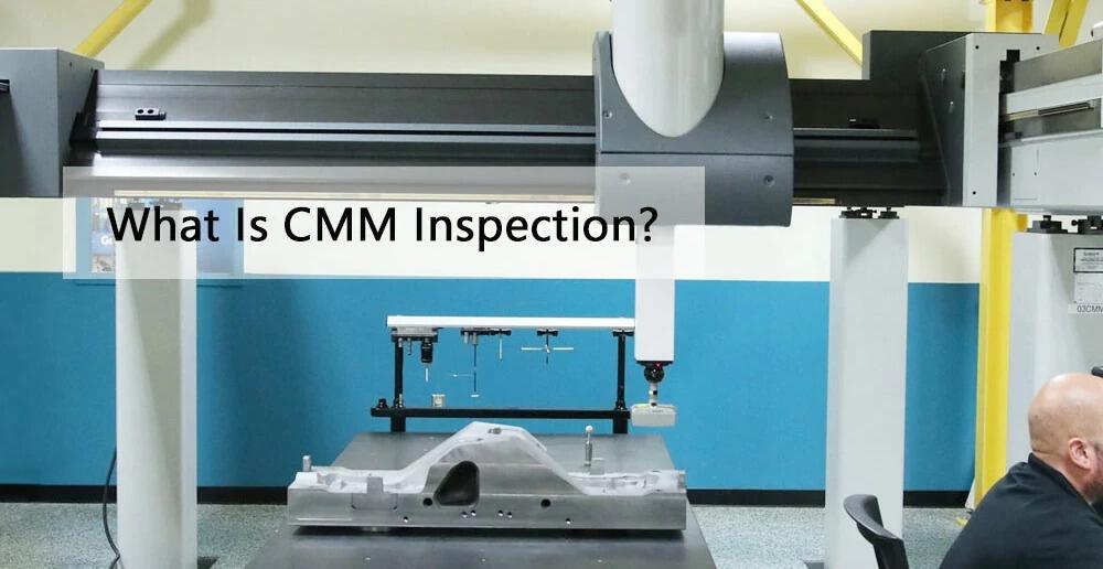
Maszyny pomiarowe współrzędne (CMM) – Te zaawansowane systemy badają części obrabiane w wielu punktach, tworząc model cyfrowy, który porównuje rzeczywiste wymiary z danymi zawartymi w specyfikacji CAD. Kontrola przy użyciu maszyny pomiarowej trójwymiarowej (CMM) pozwala zweryfikować tolerancje z dokładnością do ±0,0001 cala i zapewnia udokumentowany dowód zgodności.
Mierniki GO/NO-GO – W przypadku produkcji masowej suwmiarki kontrolne umożliwiają szybką weryfikację typu „zatwierdzone / odrzucone”. Jeśli suwmiarka pasuje (lub nie pasuje) zgodnie z projektem, część spełnia wymagane tolerancje. Ta metoda rezygnuje z szczegółowych danych pomiarowych na rzecz szybkości kontroli.
Sterowanie procesem statystycznym (spc) – Zamiast kontrolować każdą pojedynczą część, statystyczna kontrola procesu (SPC) pobiera próbki z produkcji w ustalonych odstępach czasu i śledzi trendy wymiarowe. Wykresy kontrolne ujawniają moment, w którym proces zaczyna się przesuwać w kierunku granic tolerancji, umożliwiając wprowadzenie korekt jeszcze przed wystąpieniem wad. To proaktywne podejście zapewnia utrzymanie wysokiej jakości w całym przebiegu produkcji precyzyjnych części obrabianych.
Profilometry powierzchni – Te urządzenia mierzą wartości Ra, przesuwając głowicę pomiarową po powierzchniach, co pozwala ilościowo określić chropowatość, której nie można ocenić wizualnie. Krytyczne powierzchnie uszczelniające oraz powierzchnie osi łożysk często wymagają udokumentowanych odczytów profilometru.
Zrozumienie tych metod kontroli pozwala na określenie odpowiednich wymagań jakościowych przy zakupie części tokarskich. Wymaganie raportów z pomiarów wykonywanych za pomocą maszyn pomiarowych współrzędnościowych (CMM) dla krytycznych wymiarów zapewnia obiektywne potwierdzenie zgodności z tolerancjami, podczas gdy wdrożenie statystycznej kontroli procesu (SPC) świadczy o zaangażowaniu dostawcy w zapewnienie stałej jakości, a nie jedynie reaktywną sortowanie produktów.
Po ustaleniu podstaw tolerancji kolejnym zagadnieniem staje się sposób, w jaki te wymagania precyzyjne różnią się w poszczególnych branżach – oraz konkretne certyfikaty mające znaczenie dla danego zastosowania.
Branżowe wymagania i normy dotyczące obróbki skrawaniem
Teraz, gdy zrozumiałeś tolerancje i podstawy precyzji, oto rzeczywistość: te wymagania wyglądają zupełnie inaczej w zależności od branży, której się obsłuży. Tolerancja akceptowalna dla sprzętu rolniczego natychmiast zdyskwalifikowałaby element przeznaczony do silnika odrzutowego. Zrozumienie tych sektorowych wymagań pozwala skutecznie komunikować się z dostawcami oraz ustalać odpowiednie oczekiwania dotyczące projektów obróbki skrawaniem w produkcji.
Wymagania w zakresie obróbki skrawaniem w przemyśle lotniczo-kosmicznym
Wyobraź sobie element, który musi działać bezbłędnie na wysokości 40 000 stóp, wytrzymując skrajne wahania temperatury, drgania oraz cykle obciążenia mierzone w milionach. To właśnie rzeczywistość pracy operatora CNC w przemyśle lotniczo-kosmicznym – gdzie awaria nie jest jedynie uciążliwa, lecz potencjalną katastrofą.
Obróbka przemysłowa elementów lotniczych i kosmicznych obejmuje materiały, które stanowią wyzwanie dla każdej warsztatowej pracowni. Stopy tytanu, Inconel oraz inne egzotyczne superstopy odpornościowe na ciepło i korozję są również trudne w obróbce skrawaniem. Te materiały podlegające wytężeniu przy obróbce wymagają specjalistycznego narzędziowania, obniżonych prędkości skrawania oraz doświadczonych operatorów znających ich zachowanie. Metody obróbki stali nie mogą być bezpośrednio przeniesione na superstopy niklowe.
Wymagania dotyczące dopuszczalnych odchyłek geometrycznych doprowadzają wyposażenie do granic jego możliwości. Kluczowe elementy lotnicze często określają tolerancje ±0,0005 cala lub jeszcze ścislsze, a wymagania dotyczące chropowatości powierzchni wyrażane są jednocyfrowymi wartościami Ra. Każda wymiar ma znaczenie, ponieważ montaż elementów lotniczych często obejmuje dziesiątki części współpracujących ze sobą, co prowadzi do kumulacji tolerancji.
Jednak sama precyzja nie uprawnia jeszcze warsztatu do wykonywania zleceń lotniczych. Wymagania certyfikacyjne tworzą dodatkowe bariery:
- Certyfikat AS9100 – ten specyficzny dla branży lotniczej standard zarządzania jakością opiera się na normie ISO 9001 z wzmocnionymi wymaganiami dotyczącymi śledzalności, zarządzania ryzykiem oraz dokumentacji
- Pełna śledzalność materiałów – Każda partia metalu musi być śledzona od surowca przez gotowy element, w tym zapisy dotyczące obróbki cieplnej, analiz chemicznych oraz wyników badań fizycznych
- Rozległe Protokoły Testowania – Badania nieniszczące (NDT), weryfikacja wymiarowa oraz potwierdzenie właściwości materiału są standardowymi wymaganiami
- Długoterminowe przechowywanie dokumentacji – Dokumentację należy przechowywać przez co najmniej siedem lat, przy czym niektóre programy wymagają dłuższych okresów
Inwestycja w certyfikację AS9100 zwykle wymaga 12–18 miesięcy przygotowania. Po uzyskaniu certyfikatu przedsiębiorstwa podlegają regularnym audytom nadzorczym w celu utrzymania zgodności. Ten barierą wejścia wyjaśnia, dlaczego dostawcy kwalifikowani do przemysłu lotniczego cieszą się wyższymi cenami — a także dlaczego zakupujący muszą zweryfikować ważność certyfikatów przed złożeniem zamówień.
Wymagania produkcyjne branży motocyklowej
Przesuń swoje zainteresowanie z nieba na autostradę — a priorytety obróbki metali ulegają całkowitej zmianie. Obróbka metalowa w produkcji motocyklowej i samochodowej skupia się na wysokiej jednorodności masowej, optymalizacji kosztów oraz precyzji dostaw zapewniającej ciągłość pracy linii montażowych.
Podczas gdy w przemyśle lotniczym może być produkowanych kilkadziesiąt sztuk określonego komponentu rocznie, w produkcji motocyklowej i samochodowej liczba ta wynosi tysiące lub miliony sztuk. Taka skala produkcji fundamentalnie zmienia ekonomię procesu. Koszty przygotowania stanowiska, które byłyby uciążliwe przy produkcji dziesięciu sztuk, stają się zaniedbywalne przy produkcji dziesięciu tysięcy sztuk. Skrócenie czasu cyklu o kilka sekund przekłada się na znaczne oszczędności kosztów w skali całej produkcji.
Obróbka CNC elementów metalowych przeznaczonych do zastosowań motocyklowych i samochodowych wymaga równowagi między jakością a presją kosztową. Dopuszczalne odchylenia wymiarowe mieszczą się zwykle w zakresie od ±0,001" do ±0,005" — są one wymagające, ale osiągalne przy prawidłowo konserwowanym sprzęcie. Wyzwaniem jest utrzymanie tej spójności w trakcie długotrwałych serii produkcyjnych, podczas których zużycie narzędzi, dryf termiczny oraz zmienność materiału zagrażają stabilności wymiarowej.
Dostawa just-in-time (JIT) dodaje kolejny wymiar. Producenci samochodów minimalizują zapasy, planując dostawy tak, aby dotarły dokładnie wtedy, gdy są potrzebne. Opóźnione przesyłki powodują zatrzymanie linii montażowych, co wiąże się z ogromnymi kosztami. Przysłane wcześniej części zajmują miejsce w magazynie i blokują kapitał. Dostawcy obrabiarek produkcyjnych muszą zsynchronizować swoje działania z harmonogramami klientów.
Ramka certyfikacyjna odzwierciedla te priorytety:
- Certyfikacja IATF 16949 – Międzynarodowy Zespół Roboczy ds. Motocykli i Samochodów (IATF) skupia się na zapobieganiu wadom, ograniczaniu zmienności oraz eliminacji marnotrawstwa w całym łańcuchu dostaw
- Sterowanie procesem statystycznym (spc) – Ciągłe monitorowanie krytycznych wymiarów pozwala identyfikować trendy jeszcze przed powstaniem wad
- Proces Zatwierdzania Części Produkcji (PPAP) – Formalna dokumentacja potwierdzająca, że proces produkcyjny jest w stanie systematycznie wytwarzać części zgodne ze specyfikacją
- Rozwój jakości u dostawców – Producenci samochodów (OEM) aktywnie współpracują z dostawcami w celu doskonalenia procesów i obniżania kosztów
Wdrożenie normy IATF 16949 wymaga zaangażowania kierownictwa najwyższego szczebla, szczegółowej analizy luk oraz ciągłego szkolenia pracowników. Standard ten podkreśla myślenie oparte na procesach oraz zarządzanie ryzykiem – traktując jakość jako system, a nie jedynie działalność kontrolną. Dostawcy, którzy uzyskali certyfikat, wykazują swoją zdolność do spełnienia wymagających standardów branży motocyklowej i motoryzacyjnej.
Standardy precyzji w przemyśle urządzeń medycznych
Obróbka elementów urządzeń medycznych zajmuje wyjątkową pozycję, w której precyzja spotyka się ze złożonością przepisów prawnych. Komponenty wszczepiane w ciele ludzkim lub stosowane w sprzęcie diagnostycznym muszą spełniać wymagania wykraczające poza samą dokładność wymiarową.
Wybór materiału staje się kluczowy w sposób, jaki inne branże nie doświadczają. Zgodność biologiczna — zdolność materiału do funkcjonowania bez wywoływania niekorzystnych reakcji w tkankach żywych — ogranicza wybór do sprawdzonych stopów. Tytan, stopy kobaltu i chromu oraz określone gatunki stali nierdzewnej dominują w zastosowaniach medycznych. Każdy z nich wymaga zweryfikowanych parametrów obróbki skrawaniem, aby osiągnąć wymagane cechy powierzchniowe bez zanieczyszczenia.
Jakość powierzchni nabiera zwiększonego znaczenia. Powierzchnie implantów muszą zapobiegać kolonizacji bakteryjnej i jednocześnie sprzyjać integracji tkankowej. Wymagania dotyczące chropowatości często obejmują zarówno minimalne, jak i maksymalne wartości Ra — zbyt gładka powierzchnia utrudnia wzrost kości, natomiast zbyt chropowata sprzyja rozwojowi infekcji. Te podwójne wymagania wymagają precyzyjnej kontroli procesu.
Wymagania dotyczące śledzalności przekraczają nawet standardy stosowane w przemyśle lotniczym. Każdy komponent musi być śledzony w odniesieniu do konkretnych partii materiałów, maszyn, operatorów oraz parametrów procesu. Gdy po latach od wszczepienia pojawi się problem, dochodzenie musi umożliwić dokładne odtworzenie sposobu wytworzenia danej części.
Ramy regulacyjne kształtują każdy aspekt produkcji urządzeń medycznych:
- Certyfikat ISO 13485 – Standard zarządzania jakością specyficzny dla urządzeń medycznych, który kładzie nacisk na zarządzanie ryzykiem oraz kontrolę projektowania
- Zgodność z wymogami FDA – Producentom z USA należy zarejestrować swoje obiekty produkcyjne, stosować obowiązujące zasady dobrej praktyki produkcyjnej (cGMP) oraz prowadzić obszerne dokumentacje
- Wymagania dotyczące weryfikacji – Procesy muszą zostać oficjalnie zweryfikowane, aby wykazać, że stale zapewniają uzyskanie wyrobów zgodnych ze specyfikacją
- Czyste środowiska produkcyjne – Warunki kontrolowane zapobiegają zanieczyszczeniom, które mogłyby zagrozić bezpieczeństwu pacjentów
Dopasowanie Państwa wymagań do standardów branżowych
W jaki sposób te wymagania specyficzne dla danego sektora wpływają na decyzje związane z obróbką skrawaniem? Rozważ poniższe czynniki podczas oceny dostawców lub rozwoju własnych kompetencji:
| Czynnik | Aeronautyka i kosmonautyka | Motoryzacyjny | Medycyna |
|---|---|---|---|
| Typowe tolerancje | ±0,0005" lub mniejsza | ±0,001" do ±0,005" | ±0,0005" do ±0,002" |
| Główne materiały | Tytan, Inconel, stopy aluminium | Stal, aluminium, żeliwo | Tytan, stop kobalt-chrom, stal nierdzewna przeznaczona do zastosowań medycznych |
| Wolumeny produkcji | Niski do średni | Wysoki do bardzo wysokiego | Niski do średni |
| Kluczowa Certyfikacja | AS9100 | IATF 16949 | ISO 13485 |
| Priorytet krytyczny | Bezwzględna niezawodność, śledzoność | Efektywność kosztowa, terminy dostawy | Zgodność z wymogami biokompatybilności, dokumentacja |
Zrozumienie tych branżowo-specyficznych wymagań pozwala zadawać właściwe pytania podczas zakupu elementów wykonanych metodą obróbki skrawaniem. Zakład doskonale przystosowany do masowej produkcji części samochodowych może nie posiadać doświadczenia w obróbce materiałów egzotycznych wymaganych w przemyśle lotniczym. Natomiast zakład certyfikowany do produkcji wyrobów medycznych może nie zapewniać konkurencyjności cenowej wymaganej w programach motocyklowych lub samochodowych. Dopasowanie kompetencji do konkretnej branży gwarantuje znalezienie partnerów zdolnych spełnić rzeczywiste potrzeby klienta.
Gdy wymagania branżowe zostaną wyjaśnione, pojawia się kolejne strategiczne pytanie: kiedy obróbka skrawaniem jest bardziej uzasadniona niż alternatywne metody wytwarzania, takie jak odlewanie, kucie czy wytwarzanie przyrostowe?
Kiedy wybrać obróbkę skrawaniem zamiast innych metod wytwarzania
Rozumiesz procesy, opcje wyposażenia, допuszczalne odchylenia i wymagania branżowe. Ale oto strategiczne pytanie, które oddziela świadome decyzje od kosztownych błędów: kiedy toczenie (czy ogólnie obróbka skrawaniem) jest rzeczywiście uzasadnione w porównaniu do odlewania, kucia, drukowania 3D lub wtryskiwania? Każda metoda produkcji ma swoje obszary zastosowania — a nieodpowiedni wybór może oznaczać nadpłacanie, przekroczenie terminów czy otrzymanie części, które po prostu nie działają.
Obróbka skrawaniem to proces ubytkowy, który świetnie sprawdza się w określonych sytuacjach, ale nie zawsze jest optymalnym wyborem. Zrozumienie, gdzie obróbka skrawaniem znajduje zastosowanie w stosunku do innych metod, pozwala na określenie właściwego podejścia od samego początku, oszczędzając tym samym czas i budżet.
Obróbka skrawaniem vs. produkcja przyrostowa
Wzrost popularności drukowania 3D wywołał liczne debaty na temat „obróbki skrawaniem kontra produkcja przyrostowa”. Kiedy więc każda z tych metod okazuje się najlepszym rozwiązaniem?
Wytwarzanie przyrostowe tworzy elementy warstwa po warstwie, umożliwiając uzyskanie złożonych geometrii wewnętrznych, których nie da się osiągnąć za pomocą tradycyjnych metod frezowania. Przykładami mogą być struktury siatkowe, kanały chłodzące dopasowane do kształtu części lub organiczne formy zoptymalizowane za pomocą projektowania generatywnego. Jeśli Twój element zawiera przewody wewnętrzne lub części puste, do których zwykła maszyna frezująca po prostu nie jest w stanie dotrzeć, wytwarzanie przyrostowe otwiera możliwości niedostępne przy obróbce skrawaniem.
Jednak obróbka skrawaniem i wytwarzanie konstrukcyjne przewyższają wytwarzanie przyrostowe w kilku kluczowych obszarach:
- Właściwości materiału – Elementy wykonane metodą skrawania pochodzą z pełnych prętów lub wykutek o znanych i spójnych właściwościach mechanicznych. Materiały stosowane w wytwarzaniu przyrostowym często wykazują zmienność wytrzymałości w zależności od kierunku oraz mogą wymagać obróbki dodatkowej, aby osiągnąć porównywalne właściwości.
- Opracowanie powierzchni – Operacja frezowania regularnie zapewnia chropowatość powierzchni na poziomie 32 µin Ra lub lepszą. Większość procesów wytwarzania przyrostowego pozostawia chropowatość powierzchni w zakresie 200–500 µin Ra, co wymaga dodatkowej obróbki skrawaniem powierzchni stykowych.
- Precyzja – Standardowe tolerancje CNC wynoszące ±0,001" do ±0,005" przewyższają dokładność osiąganą przez większość technologii addytywnych bez konieczności obróbki dodatkowej.
- Ekonomika produkcji – Dla ilości przekraczających prototypy koszty produkcji na pojedynczą część w procesie frezowania znacznie spadają wraz ze wzrostem objętości zamówienia. Koszty produkcji metodami addytywnymi pozostają stosunkowo stałe niezależnie od ilości.
Jak to wygląda w praktyce? Wiele elementów wykonywanych metodami addytywnymi wymaga obróbki skrawaniem dla kluczowych cech geometrycznych — co prowadzi do hybrydowego procesu produkcyjnego, a nie do czystego wyboru jednej z metod. Rozważ zastosowanie technik addytywnych tam, gdzie geometria tego wymaga, ale spodziewaj się udziału obróbki skrawaniem przy precyzyjnych powierzchniach styku.
Kiedy odlewanie lub kucie są rozsądnym wyborem
Odlewanie i kucie to metody kształtowania materiału, które tworzą przedmiot poprzez formowanie, a nie usuwanie nadmiaru materiału. Oba procesy są szczególnie opłacalne tam, gdzie obróbka skrawaniem staje się ekonomicznie nieuzasadniona.
FORMOWANIE polega na wlewaniu stopionego materiału do form, w których materiał zestalnia się, tworząc kształty zbliżone do gotowego produktu. Odlewanie w formach wytapialnych pozwala uzyskać wyjątkową szczegółowość, podczas gdy odlewanie w piasku umożliwia produkcję bardzo dużych elementów. Odlewanie jest opłacalne ekonomicznie w przypadku:
- Złożonych wewnętrznych wnęk, których wykonanie wymagałoby nadmiernej ilości usuwanego materiału
- Objętości produkcji uzasadniają inwestycję w oprzyrządowanie (zazwyczaj 500+ sztuk)
- Materiały trudno są obrabiane, ale dobrze nadają się do odlewania (pewne stopy aluminium, żeliwo szare)
- Redukcja masy dzięki zoptymalizowanej geometrii ma większe znaczenie niż ostateczna precyzja
Jaki jest kompromis? Odlewy wymagają zazwyczaj dodatkowej obróbki skrawaniem powierzchni montażowych, elementów gwintowanych oraz precyzyjnych otworów. Tolerancje surowych odlewów mieszczą się w zakresie ±0,010" do ±0,030" — co jest akceptowalne dla wielu cech, ale niewystarczające dla pasowań i krytycznych wymiarów.
Wyroby szlachetne kształtują nagrzanego metalu za pomocą siły ściskającej, tworząc części o lepszej strukturze ziarnistej i właściwościach mechanicznych. Podwozia samolotów, wały korbowe oraz elementy poddawane wysokim naprężeniom często zaczynają swój cykl produkcyjny jako wykonywane przez kucie części właśnie dlatego, że ten proces dopasowuje kierunek przepływu ziaren materiału do torów naprężeń. Kucie zapewnia:
- Zwiększoną wytrzymałość w porównaniu z metodami obróbki skrawaniem z pełnego materiału
- Mniejsze zużycie materiału niż przy cięciu z dużych bloków
- Lepszą odporność na zmęczenie dla części obciążanych cyklicznie
Podobnie jak odlewy, kowanki wymagają obróbki wykańczającej. Kucie tworzy szkicowy kształt z ulepszonymi właściwościami; obróbka skrawaniem zapewnia końcowe wymiary i jakość powierzchni.
Porównanie wtryskiwania
W przypadku komponentów plastycznych wtryskiwanie dominuje w produkcji wysokogłębokościowej. Roztopiony polimer wpływa do precyzyjnych form, zastygając w złożone kształty w cyklach trwających kilka sekund. Przy ilościach przekraczających 10 000 sztuk koszt jednostkowy wtryskiwania spada znacznie poniżej poziomu, jaki można osiągnąć przy użyciu dowolnej maszyny i operacji obróbkowych.
Jednak obróbka skrawaniem tworzyw sztucznych ma sens, gdy:
- Ilość prototypów nie uzasadnia inwestycji w formę (5 000–100 000 USD+)
- Kontynuowane są iteracje projektowe, a ustalenie ostatecznej geometrii na potrzeby wykonania narzędzi jest jeszcze zbyt wcześniejsze
- Wymagania materiałowe narzucają zastosowanie tworzyw inżynierskich, które dobrze poddają się obróbce skrawaniem, ale źle wtryskiwaniu
- Ścisłe допусki przekraczają typowe możliwości wtryskiwania (±0,005 cala i ścislsze)
Ramka decyzyjna do wyboru procesu
W jaki sposób systematycznie dokonujesz wyboru między tymi opcjami? Rozważ tę kompleksową porównawczą analizę w zakresie czynników, które zwykle decydują o decyzjach produkcyjnych:
| Czynnik | Obróbka CNC | druk 3D (metal) | FORMOWANIE | Wyroby szlachetne | Wtryskowanie materiałów |
|---|---|---|---|---|---|
| Opcje materiałowe | Doskonała — metale, tworzywa sztuczne, kompozyty | Ograniczona — konkretne proszki stopowe | Dobra — większość stopów nadających się do odlewania | Umiarkowana — wyłącznie metale nadające się do kucia | Tworzywa sztuczne oraz niektóre metale (proces MIM) |
| Złożoność geometryczna | Umiarkowana — ograniczona dostępnością narzędzi | Doskonała — możliwe wykonanie elementów wewnętrznych | Dobra — możliwe wykonanie wnęk wewnętrznych | Ograniczona — stosunkowo proste kształty | Doskonałe — złożone geometrie plastyczne |
| Optymalny zakres wielkości serii | 1–10 000 elementów | 1–100 sztuk | 500–100 000+ sztuk | 1 000–100 000+ sztuk | 10 000–1 000 000+ sztuk |
| Koszt jednostkowy (niska seria) | Umiarkowany | Wysoki | Bardzo wysokie (amortyzacja narzędzi) | Bardzo wysokie (koszty matryc) | Ekstremalnie wysokie (koszty form) |
| Koszt jednostkowy (duża objętość) | Wysokie (wymagające dużej ilości pracy ręcznej) | Bardzo wysokie (brak korzyści skali) | Niski | Niski | Bardzo niska |
| Czas realizacji (pierwsza sztuka) | Dni do tygodni | Dni do tygodni | Kilka tygodni do miesięcy (oprzyrządowanie) | Tygodnie do miesięcy (produkcja matryc) | Tygodnie do miesięcy (wykonanie formy) |
| Precyzja wykonania | ±0,0005 cala osiągalne | ±0,005 cala typowo (często wymagana obróbka dodatkowa) | ±0,010 cala do ±0,030 cala w stanie odlewu | ±0,015 cala do ±0,030 cala w stanie wykowaniu | ±0,002 cala do ±0,005 cala (większe odchylenia przy precyzyjnych formach) |
| Inwestycja w narzędzia | Niski (standardowe oprzyrządowanie) | Brak (tylko płytka budowy) | Średnie do wysokich (2000–50 000 USD i więcej) | Wysokie (10 000–100 000 USD i więcej) | Wysokie (5000–100 000 USD i więcej) |
Uwagi dotyczące projektowania pod kątem łatwości produkcji
Projekt samej części często decyduje, który proces jest najbardziej odpowiedni. Projektowanie z myślą o wykonalności produkcyjnej (DFM) oznacza dostosowanie geometrii tak, aby wykorzystać zalety konkretnego procesu i uniknąć jego ograniczeń.
Zasady DFM w obróbce skrawaniem obejmują:
- Unikaj głębokich kieszeni o małych promieniach zaokrąglenia – Długie i cienkie frezy odkształcane uginają się i drżą; projektuj narożniki kieszeni z promieniami zaokrąglenia odpowiadającymi dostępnym narzędziom
- Minimalizuj przygotowania – Elementy dostępne z jednego kierunku zmniejszają liczbę operacji manipulacyjnych i poprawiają dokładność
- Określ tylko niezbędną dokładność – Ścisłe допусki na każdą wymiar zwiększają koszty bez dodawania wartości
- Rozważ standardowe rozmiary – Projektowanie z uwzględnieniem dostępnych prętów redukuje odpady materiału
Porównaj to z zasadami projektowania dla odlewnictwa (DFM), gdzie jednolita grubość ścian zapobiega wadom skurczowym, kąty wyciągu umożliwiają wyjmowanie odlewów z formy, a duże promienie zaokrągleń zmniejszają koncentrację naprężeń. Projekt zoptymalizowany pod kątem frezowania może być słabo nadający się do odlewnictwa i odwrotnie.
Czynniki wpływające na koszty poza ceną jednostkową
Przy porównywaniu metod wytwarzania należy brać pod uwagę nie tylko podane ceny sztuki, lecz także całkowite koszty realizacji programu:
- Odpady materialne – Frezowanie z litego materiału generuje wiórkę; procesy bliskie końcowej postaci (near-net-shape) minimalizują odpady. W przypadku drogich materiałów, takich jak tytan czy Inconel, wykorzystanie materiału ma decydujący wpływ na opłacalność.
- Inwestycja w narzędzia – Formy odlewnicze, matryce kuźnicze oraz formy wtryskowe wymagają znacznych nakładów kapitałowych na etapie przygotowania. W przypadku frezowania koszty narzędzi są rozłożone na standardowe wkładki i frezy.
- Wymagania dotyczące pracy – Produkcja maszynowa wymaga nadzoru operatora, programowania oraz kontroli jakości na poziomach zależnych od danego procesu.
- Operacje wtórne – Procesy bliskie końcowej postaci często wymagają obróbki wykończeniowej. Należy uwzględnić te koszty przy porównaniach.
- Skutki dla zapasów – Procesy z długim czasem realizacji narzędzi sprzyjają dużym partiom produkcji; obróbka skrawaniem umożliwia elastyczność dostaw w trybie just-in-time.
Dokonywanie decyzji dotyczącej procesu
Przy uwzględnieniu wszystkich czynników poniżej przedstawiono praktyczny ramowy schemat podejmowania decyzji:
- Zacznij od ilości – Dla 1–100 sztuk zwykle lepsze są obróbka skrawaniem lub technologia addytywna. Powyżej 10 000 sztuk rozważ odlewanie, kucie lub formowanie.
- Oceń geometrię – Złożone cechy wewnętrzne sprzyjają technologii addytywnej lub odlewaniu. Proste kształty zewnętrzne z wysoką dokładnością richają obróbki skrawaniem.
- Oceń wymagania materiałowe – Stopy egzotyczne mogą ograniczać dostępne opcje. Standardowe materiały umożliwiają zastosowanie wszystkich procesów.
- Rozważ harmonogram – Potrzebujesz części w ciągu kilku dni? Wybierz frezowanie lub technologię przyrostową. Masz miesiące na opracowanie narzędzi? Procesy bliskie końcowej postaci stają się wtedy opłacalne.
- Oblicz całkowity koszt – Włącz do porównania koszty narzędzi, operacje wtórne oraz wymagania jakościowe.
Zrozumienie, kiedy wybrać frezowanie – a kiedy alternatywne metody są bardziej uzasadnione – pozwala na dobranie odpowiedniego procesu już na etapie rozpoczęcia projektu. Jednak nawet przy wybraniu optymalnego procesu typowe wady mogą zakłócić produkcję. Poznanie sposobów zapobiegania tym problemom jeszcze przed ich wystąpieniem stanowi kolejną niezbędną umiejętność.
Typowe wady frezowania i sposoby ich zapobiegania
Wybrałeś odpowiedni proces, określiłeś odpowiednie допусki i wybrano kompetentnego partnera. Ale oto frustrująca rzeczywistość: nawet dobrze zaplanowane projekty mogą generować wadliwe części. Zrozumienie defektów obróbkowych, które zakłócają produkcję – oraz wiedza na temat ich zapobiegania – stanowi kluczową różnicę między sukcesem projektu a kosztowną przeróbką. Niezależnie od tego, czy dopiero zaczynasz przygodę z podstawowymi pojęciami obróbki skrawaniem, czy też rozwiązujesz uporczywy problem produkcyjny, ten praktyczny przewodnik dotyczy najbardziej prawdopodobnych do napotkania trudności.
Problemy z wykończeniem powierzchni i ich rozwiązania
Gdy Twoje części obrobione skrawaniem wracają z chropowatą, paskowaną lub niestabilną powierzchnią, za takie wady wykończenia powierzchni odpowiadają zwykle defekty powierzchniowe. Problemy te wpływają zarówno na wygląd, jak i funkcjonalność – szczególnie w przypadku powierzchni uszczelniających oraz powierzchni stykających się ze sobą.
Ślady rozmowy pojawiają się jako regularne, falopodobne wzory na powierzchniach obrobionych skrawaniem. Co je powoduje? Wibracje podczas skrawania — niezależnie od niedostatecznej sztywności, niewłaściwych prędkości czy rezonansu między narzędziem a przedmiotem obrabianym. Zdaniem ekspertów z zakresu narzędzi do obróbki skrawaniem drgania (chatter) stanowią jeden z najczęściej występujących i najbardziej irytujących problemów, z jakimi stykają się tokarze i frezarki.
Strategie zapobiegania obejmują:
- Zmniejszenie wystającego odcinka narzędzia w celu zwiększenia sztywności
- Dostosowanie prędkości wrzeciona w celu uniknięcia częstotliwości rezonansowych
- Zwiększenie posuwu (przeciwnie do intuicji, czasem szybsze posuwy zmniejszają drgania)
- Stosowanie uchwytów narzędziowych zapobiegających wibracjom przy operacjach z dużym wychyleniem narzędzia
Ślady narzędzi pozostawiają widoczne linie lub wzory odzwierciedlające ścieżkę narzędzia. Choć pewien stopień znakowania jest nieunikniony w obróbce metali, nadmierne jego nasilenie wskazuje na istnienie problemów. Najczęstsze przyczyny to zużyte krawędzie tnące, niewłaściwe prędkości posuwu lub słabe usuwanie wióra. Zmiana ostrzy na bardziej ostre, optymalizacja parametrów skrawania oraz zapewnienie odpowiedniego przepływu chłodziwa zwykle rozwiązuje te problemy.
Uszkodzenia powierzchni obejmuje oparzenia, rozrywania i rozsmarowywanie — szczególnie częste przy materiałach trudnych do obróbki. Gdy ciepło gromadzi się szybciej, niż się rozprasza, powierzchnia obrabianego przedmiotu ulega degradacji. Zastosowanie chłodziwa o dużej objętości i wysokim ciśnieniu — lub w niektórych przypadkach całkowite zaniechanie jego stosowania — może faktycznie poprawić wyniki dzięki skuteczniejszemu zarządzaniu warunkami termicznymi.
Problemy z dokładnością wymiarową
Brzmi skomplikowanie? Problemy wymiarowe często wynikają z prostych przyczyn. Gdy pomiary części wychodzą poza dopuszczalne tolerancje, systematowe diagnozowanie pozwala zidentyfikować źródło problemu.
Dryft wymiarowy występuje, gdy części stopniowo odchylają się od specyfikacji w trakcie serii produkcyjnej. Obróbka rozpoczyna się prawidłowo, ale już przy pięćdziesiątej lub setnej części wymiary ulegają przesunięciu. Główne przyczyny to:
- Rozszerzenie termiczne – W miarę nagrzewania się maszyny jej elementy ulegają rozszerzeniu. Wrzeciono pracujące przez kilka godzin mierzy się wyraźnie większą długość, co przesuwa pozycję narzędzia względem obrabianego przedmiotu.
- Zużycia narzędzi – Krawędzie tnące stopniowo tępią się, zmieniając efektywne wymiary. Wkład tokarski zużyty o 0,001 cala przesuwa końcowy średnicę o 0,002 cala.
- Zmiany temperatury cieczy chłodzącej – Ciecz chłodząca pochłania ciepło podczas frezowania. W miarę jej nagrzewania zmieniają się zarówno jej właściwości smarujące, jak i warunki termiczne.
Zapobieganie wymaga proaktywnego zarządzania. Pozwól maszynom osiągnąć równowagę termiczną przed wykonaniem krytycznych frezowań. Wdroż monitorowanie zużycia narzędzi – niezależnie od tego, czy odbywa się ono poprzez zaplanowane wymiany, czy pomiary w trakcie procesu. Utrzymuj temperaturę cieczy chłodzącej w zakresie określonym przez producenta.
Niewłaściwe uchwyty powodują przesuwanie się elementów podczas frezowania, generując niestabilne błędy wymiarowe. Siły występujące w trakcie obróbki mogą łatwo przesunąć słabo zamocowane przedmioty obrabiane. Objawami są niestabilne wymiary między poszczególnymi elementami oraz cechy geometryczne, które nie są prawidłowo zsynchronizowane ze sobą. Zainwestuj w profesjonalne systemy zaciskowe – wysokiej jakości uchwyty szybko zwracają się w postaci zmniejszonej ilości odpadów.
Wady związane z narzędziami
Twoje narzędzia tnące bezpośrednio decydują o jakości wykonywanych elementów. Gdy one zawiodą, zawodzą również Twoje części. Rozpoznawanie wad związanych z narzędziami pozwala na interwencję jeszcze przed eskalacją problemów.
Zadziory powstają, gdy materiał wypychany jest na zewnątrz zamiast czysto ścinany. Te wypukłe krawędzie wymagają dodatkowych operacji usuwania wyprasek, które zwiększają koszty i uciążliwość obsługi. Tworzenie wyprasek wzrasta wraz z:
- Zaokrąglonymi krawędziami tnącymi, które wypychają zamiast tnąć
- Zbyt dużymi prędkościami posuwu, powodującymi przeciążenie krawędzi tnącej
- Niewłaściwymi strategiami wyjścia narzędzia, gdy opuszcza ono przedmiot obrabiany
- Właściwościami materiału — materiały plastyczne tworzą wypraski łatwiej niż materiały kruche
Ostrze narzędzia, zoptymalizowane parametry skrawania oraz strategicznie zaprojektowana ścieżka narzędzia minimalizują tworzenie wyprasek. W przypadku nieuniknionych wyprasek należy zaplanować operacje ich usuwania jako integralną część procesu, a nie traktować ich jako niespodzianki.
Tworzenie się grzbietu zalepnego (BUE) występuje, gdy materiał przedmiotu obrabianego przyspawa się do narzędzia tnącego. Zjawisko to występuje szczególnie często przy obróbce aluminium i stali nierdzewnej. W miarę gromadzenia się materiału zmienia się efektywna geometria skrawania, pogarsza się jakość powierzchni oraz grzbiet zalepny ostatecznie odpada — czasem zabierając ze sobą fragmenty karbidu. Głównym sposobem zapobiegania tworzeniu się grzbietu zalepnego (BUE) jest zapewnienie odpowiedniej ilości chłodziwa w strefie skrawania , w połączeniu ze zwiększonym stężeniem chłodziwa w celu poprawy smarowości.
Przedwczesne uszkodzenie narzędzi prowadzi do marnotrawienia budżetu na narzędzia i zwiększa ryzyko uszkodzenia obrabianych przedmiotów. Kilka mechanizmów zużycia przyczynia się do tego zjawiska:
- Zużycie boczne – Zużycie ścierne normalne na powierzchni przyłożenia narzędzia; kontrolowane przez odpowiednie prędkości skrawania oraz zastosowanie odpornych na zużycie gatunków płytek tnących
- Zużycie kraterowe – Erozja chemiczna na powierzchni natarcia spowodowana kontaktem gorących wiórków w wysokiej temperaturze; zmniejsz prędkość skrawania lub wybierz twardsze gatunki płytek tnących
- Kraking termiczny – Pęknięcia prostopadłe do krawędzi skrawającej, wywołane szybkimi zmianami temperatury; często wskazują na niestabilne zastosowanie chłodziwa lub przerywane skrawanie
- Rozdrabnianie – Uszkodzenia krawędzi skrawającej spowodowane obciążeniem udarowym lub nadmiernymi siłami; zmniejsz posuw i zapewnij płynne wprowadzanie narzędzia w materiał
Rozwiązywanie problemów
Gdy pojawiają się wady, systematyczna diagnostyka jest skuteczniejsza niż przypadkowe korekty. Rozpocznij od następujących pytań:
- Czy problem występuje regularnie, czy okresowo? Regularne wady wskazują na przyczyny systemowe (błędne parametry skrawania, zużyte narzędzia). Okresowe problemy sugerują występowanie zmiennych czynników (niespójność materiału, efekty termiczne, problemy z uchwytem).
- Kiedy problem się rozpoczął? Nowe problemy po zmianie narzędzia, edycji programu lub zmianie partii materiału zawężają zakres badań.
- W którym miejscu na elemencie pojawia się wada? Wady występujące w określonych miejscach często wiążą się z odcinkami ścieżki narzędzia, punktami styku uchwytu lub gradientami temperatury.
Skuteczna zapobiegawczość łączy odpowiednią konserwację narzędzi, zoptymalizowane parametry skrawania oraz uwagę do środowiska obróbkowego. Śledź dane dotyczące trwałości narzędzi, aby wymieniać płytki tnące przed wystąpieniem zużycia wpływającego na jakość. Dokumentuj sprawdzone parametry dla każdego materiału i operacji. Monitoruj stężenie i stan chłodziwa. Te działania zapobiegawcze pozwalają wykryć problemy jeszcze przed powstaniem odpadów.
Zrozumienie rodzajów wad i sposobów ich zapobiegania umożliwia bardziej skuteczne ocenianie potencjalnych partnerów produkcyjnych. Jednak znajomość tego, jak wygląda dobra jakość, to tylko część równania — wybór odpowiedniego partnera obróbkowego wymaga oceny jego kompetencji, certyfikatów oraz zdolności do skalowania mocy produkcyjnej zgodnie z rosnącymi potrzebami.
Wybór odpowiedniego partnera obróbkowego do realizacji projektu
Opanowałeś procesy, допuszczalne odchylenia i strategie zapobiegania wadom. Teraz nadszedł moment decyzji, która często decyduje o powodzeniu lub niepowodzeniu projektu: wybór odpowiedniego partnera z zakresu obróbki skrawaniem. Niezależnie od tego, czy zamawiasz pierwszy prototyp, czy skalujesz produkcję do dużych serii, ocena usług maszynowych wymaga spojrzenia poza podanymi cenami, aby rzetelnie ocenić rzeczywiste możliwości. Nieodpowiedni wybór oznacza przegapione terminy, problemy z jakością oraz koszty, które znacznie przekraczają pierwotne szacunki.
Wybieraj warsztat maszynowy tak, jak wybierałbyś chirurga — kwalifikacje mają znaczenie, ale równie istotne jest doświadczenie w pracy z konkretnym przypadkiem. Warsztat doskonały w obróbce tytanu dla przemysłu lotniczego może mieć trudności z komponentami motocyklowymi produkowanymi w dużych ilościach. Z kolei warsztat świetnie radzący sobie z szybkimi prototypami może nie dysponować wystarczającą mocą produkcyjną do długotrwałej produkcji seryjnej. Zrozumienie, co należy oceniać, oraz jakie pytania zadawać, pozwala znaleźć partnerów rzeczywiście odpowiadających Twoim potrzebom.
Ocenianie możliwości warsztatu obróbkowego
Zanim przejdziemy do certyfikatów i systemów jakości, rozpocznijmy od podstawowej oceny kompetencji. Co to jest tokarka w ich warsztacie — ręczna tokarka uniwersalna czy wieloosiowy centrum tokarskie CNC? Odpowiedź na to pytanie wiele mówi o ich potencjale dokładności i wydajności produkcyjnej.
Przy weryfikacji potencjalnych dostawców należy zbadać następujące kluczowe obszary:
- Jakie tolerancje są w stanie one systematycznie zachować? Każdy warsztat może deklarować ścisłe tolerancje — poproś o udokumentowane dowody. Zażądaj raportów z kontroli jakości z ostatnich zleceń o podobnych wymaganiach. Warsztaty pewne swoich kompetencji chętnie udostępniają takie dane.
- Z jakimi materiałami pracują regularnie? Doświadczenie w obróbce konkretnych stopów ma istotne znaczenie. Parametry skrawania, które dają doskonałe rezultaty przy aluminium 6061, kończą się spektakularnym fiaskiem przy Inconelu. Zapytaj o ich wiedzę specjalistyczną dotyczącą materiałów oraz zażądaj przykładów podobnych realizacji.
- Jakie wyposażenie tokarskie posiadają? Możliwości wieloosiowego CNC, tokarki z narzędziami obrotowymi oraz wyposażenie do szlifowania znacznie rozszerzają zakres możliwych do osiągnięcia wyników. Jednak same urządzenia nie wystarczają — dokumentacja konserwacji ujawnia, czy maszyny działają zgodnie ze specyfikacją.
- Jaka jest ich zdolność do realizacji zamówień w określonym czasie? Czy mogą dostarczyć prototypów w ciągu kilku dni, a części produkcyjne zgodnie z harmonogramem? Ograniczenia pojemnościowe i istniejące zaległości bezpośrednio wpływają na termin realizacji Twojego projektu. Firmy oferujące usługi, których nie są w stanie wykonać, powodują problemy w dalszej części procesu.
- Jakie systemy zapewnienia jakości są wdrożone? Poza certyfikatami należy zapytać o kontrole podczas procesu produkcyjnego, monitorowanie statystyczne oraz procedury działań korygujących. Jakość wbudowana w proces produkcyjny wiąże się z niższymi kosztami niż kontrola jakości przeprowadzana na końcu procesu.
Nie polegaj wyłącznie na prezentacjach sprzedażowych. Jeśli to możliwe, odwiedź zakład. Nieuporządkowana hala produkcyjna świadczy o nieuporządkowanych procesach — niemal niemożliwe jest wytwarzanie spójnych, wysokiej precyzji części w chaotycznej środowisku. Szukaj dowodów systemowego podejścia: uporządkowanych narzędzi warsztatowych, jasnych instrukcji pracy oraz zaangażowanych operatorów, którzy rozumieją, co produkują i dlaczego to ma znaczenie.
Certyfikaty o znaczeniu
Certyfikaty branżowe stanowią obiektywne potwierdzenie, że dostawca utrzymuje systemy jakości zgodne z uznawanymi standardami. Jednak nie wszystkie certyfikaty mają takie samo zastosowanie w każdej sytuacji.
ISO 9001 ustala podstawowe zasady zarządzania jakością — dokumentację, kontrolę procesów oraz ciągłe doskonalenie. Jest to punkt wyjścia, a nie cel końcowy. Większość profesjonalnych warsztatów maszynowych posiada ten certyfikat jako minimalny wymóg konieczny do poważnej działalności produkcyjnej.
AS9100 dodaje wymagania specyficzne dla przemysłu lotniczego i kosmicznego do normy ISO 9001. Jeśli Twoje komponenty są stosowane w lotnictwie lub kosmonautyce, dostawcy muszą wykazać wzmocnioną śledzalność, zarządzanie ryzykiem oraz dokumentację, których wymaga ta norma. Certyfikacja wymaga 12–18 miesięcy przygotowania oraz regularnych audytów nadzorczych.
IATF 16949 obejmuje wymagania branży motocyklowej i samochodowej, skupiając się na zapobieganiu wadom, redukcji zmiennych oraz eliminacji marnotrawstwa. W łańcuchach dostaw motocyklowych i samochodowych certyfikacja ta sygnalizuje, że dostawcy rozumieją presję wynikającą z systemu just-in-time oraz oczekiwania związane z ciągłą poprawą. Wdrożenie wymaga zaangażowania kierownictwa najwyższego szczebla , szczegółowej analizy luk oraz kompleksowego szkolenia pracowników.
ISO 13485 reguluje produkcję wyrobów medycznych, wprowadzając dodatkowe wymagania dotyczące biokompatybilności, śledzalności oraz zgodności z przepisami prawymi, których nie obejmują ogólne certyfikaty.
Ponad certyfikaty warto zapytać o wdrożenie Statystycznej Kontroli Procesu (SPC). SPC monitoruje kluczowe wymiary w trakcie całej serii produkcyjnej, wykrywając trendy jeszcze przed powstaniem wad. Firmy stosujące SPC wykrywają problemy proaktywnie, a nie dopiero podczas końcowej kontroli jakości — kiedy ich usunięcie wiąże się z istotnie wyższymi kosztami.
Obiekty takie jak Shaoyi Metal Technology przedstawiają, jak w praktyce wygląda kompleksowe partnerstwo w zakresie jakości. Ich certyfikat IATF 16949 w połączeniu z rygorystycznym wdrożeniem SPC umożliwia im stałe dostarczanie komponentów o wysokiej dokładności wymiarowej — niezależnie od tego, czy chodzi o szybkie prototypowanie z czasem realizacji nawet jednego dnia roboczego, czy o skalowanie produkcji do objętości masowych. To połączenie certyfikacji, kontroli procesów i elastycznych możliwości produkcyjnych stanowi standard, którego należy szukać przy ocenie potencjalnych partnerów.
Od prototypu do produkcji seryjnej
Twoje potrzeby produkcyjne ewoluują. Partner idealny do wytworzenia dziesięciu prototypów może mieć trudności, gdy będziesz potrzebować dziesięciu tysięcy części produkcyjnych — lub odwrotnie. Zrozumienie, jak warsztaty radzą sobie z skalowaniem, pozwala uniknąć bolesnych przejść w późniejszym etapie.
Obróbka prototypów i obróbka produkcyjna wymagają różnych kompetencji. Prace prototypowe skupiają się na szybkości i elastyczności — szybkich przygotowaniach maszyn, szybkich iteracjach oraz tolerancji wobec zmian projektowych. Produkcja wymaga spójności, wydajności oraz zdolności zapewnienia wysokiej jakości w trakcie długotrwałych serii.
Oceniając skalowalność, rozważ następujące czynniki:
- Pojemność sprzętu – Czy warsztat dysponuje wystarczającą liczbą maszyn, aby obsłużyć prognozowane objętości bez przesuwania terminów innych klientów? Przemysłowy tokarka przeznaczona wyłącznie do Twoich części ogranicza ich elastyczność — a także Twoją.
- Dokumentacja procesu – Czy potrafią udokumentować to, co sprawdza się w fazie prototypowania, i niezawodnie powielać to w produkcji? Nieudokumentowana „wiedza zakladowa" wiąże się z ryzykiem w przypadku zmiany kluczowych pracowników.
- Zarządzanie łańcuchem dostaw – Czy posiadają niezawodne źródła materiałów i dostawców zapasowych? Warsztat zależny od jednego źródła staje się dla Państwa punktem pojedynczego awarii.
- Skalowanie jakości – W jaki sposób metody kontroli przystosowują się od 100-procentowej kontroli prototypów do statystycznego pobierania próbek w produkcji? Odpowiedź ujawnia, czy systemy zapewnienia jakości rozwijają się wraz ze wzrostem objętości produkcji.
Przejście od prototypu do produkcji często ujawnia luki w zakresie kompetencji. Wczesne omawianie wymagań produkcyjnych —nawet podczas wstępnych rozmów dotyczących prototypów—pomaga zidentyfikować partnerów zdolnych do rozwoju wraz z Państwa potrzebami. Warsztaty przejawiające przejrzystość w kwestii swoich ograniczeń budują większe zaufanie niż te, które obiecują wszystko, a dostarczają jedynie problemów.
Dla zastosowań motocyklowych wymagających bezproblemowego skalowania, certyfikowane zakłady z udokumentowanym doświadczeniem w przejściu od prototypów do produkcji masowej zmniejszają ryzyko przejścia. Możliwość dostarczania złożonych zespołów podwozia, niestandardowych wkładek metalowych oraz precyzyjnych komponentów w różnych zakresach objętości — od początkowych próbek po trwającą produkcję — charakteryzuje partnerów wspierających cały cykl życia produktu, a nie tylko pojedyncze jego etapy.
Wybór odpowiedniego partnera wymaga więcej niż porównania ofert cenowych. Należy ocenić, czy jego kompetencje, certyfikaty oraz moc produkcyjna są zgodne z obecnymi potrzebami oraz perspektywami rozwoju. Gdy odpowiednia podstawa zostanie ustanowiona, jesteś w stanie skutecznie wykorzystać technologie obróbki skrawaniem — temat ten ciągle ewoluuje wraz z automatyzacją, programowaniem wspomaganym sztuczną inteligencją oraz hybrydowymi podejściami do produkcji.
Kolejne kroki z pewnością w decyzjach dotyczących obróbki skrawaniem
Przeszliście od podstawowych definicji przez dobór procesów, specyfikacje tolerancji oraz ocenę partnerów. Nadszedł teraz najbardziej ekscytujący etap: technologia obróbki nie stoi w miejscu. Krajobraz produkcyjny zmienia się bardzo szybko pod wpływem innowacji zwiększających precyzję, wydajność i połączenie systemów. Zrozumienie kierunku, w jakim rozwija się branża – oraz podjęcie konkretnych działań na podstawie zdobytej wiedzy – pozwala podejmować decyzje, które odpowiadają zarówno obecnym potrzebom, jak i przyszłemu wzrostowi.
Nowe technologie przekształcające obróbkę skrawaniem
Na czym polega dziś precyzyjna obróbka skrawaniem w erze inteligentnej produkcji? Odpowiedź tkwi w technologiach, które już teraz zmieniają sposób wytwarzania części.
Integracja automatyki wykracza daleko poza podstawowe programowanie CNC. Nowoczesne technologie obróbkowe wykorzystują roboty współpracujące, które działają bezproblemowo wraz z maszynami CNC, wykonując zadania takie jak załadunek, rozładunek, usuwanie wykańczania (deburring) oraz inspekcja. Ta współpraca skraca czasy cyklu i minimalizuje błędy wynikające z ręcznego manipulowania przedmiotami – jednocześnie zwalniając wykwalifikowanych operatorów do skupienia się na złożonym rozwiązywaniu problemów zamiast na powtarzalnych czynnościach.
Programowanie wspomagane sztuczną inteligencją rewolucjonizuje optymalizację procesów. Algorytmy sztucznej inteligencji analizują ogromne zbiory danych pochodzące z czujników maszyn, wykrywając wzorce, których operatorzy ludzcy mogliby nie zauważyć. Wynik? Poprawa prędkości skrawania, wydłużenie żywotności narzędzi oraz lepsza jakość powierzchni osiągana dzięki korektom parametrów w czasie rzeczywistym. Modele uczenia maszynowego przewidują teraz potencjalne awarie jeszcze przed ich wystąpieniem, umożliwiając utrzymanie zapobiegawcze, które zapobiega kosztownemu simply przestojowi.
Technologia Digital Twin tworzy wirtualne repliki fizycznych maszyn i procesów. Te cyfrowe modele pozwalają producentom na symulowanie operacji, testowanie różnych scenariuszy oraz optymalizację produkcji bez ryzyka dla rzeczywistego sprzętu lub materiałów. Gdy pojawiają się problemy, cyfrowe bliźniaki pomagają szybciej zidentyfikować ich pierwotne przyczyny niż tradycyjne metody diagnozowania.
Hybrydowe technologie produkcyjne łączy procesy addytywne i subtrakcyjne w pojedynczych maszynach. Wyobraź sobie wydrukowanie części w przybliżonej końcowej formie, a następnie precyzyjne obróbkę krytycznych powierzchni – wszystko w jednej konfiguracji. Takie podejście umożliwia tworzenie geometrii wcześniej niemożliwych do uzyskania, jednocześnie zmniejszając odpady materiałowe i konsolidując operacje.
Te innowacje w zakresie obróbki mechanicznej łączy wspólna cecha: łączność. Integracja z przemysłem 4.0 oznacza, że maszyny komunikują się z centralnymi systemami, platformy chmurowe umożliwiają zdalne monitorowanie, a dane płyną bezproblemowo przez całe operacje. Dla producentów oceniających potencjalnych partnerów te możliwości coraz częściej stanowią kluczowy czynnik rozgraniczający liderów od opóźnionych uczestników rynku.
Rozwijanie swojej wiedzy z zakresu obróbki skrawaniem
Jak nauczyć się obróbki skrawaniem w dzisiejszym środowisku? Ścieżka zależy od Twoich celów, ale kilka podejść nadaje się dla każdego, kto pragnie głębszego zrozumienia tej dziedziny.
Dla inżynierów i specjalistów ds. zakupów wiedza zdobyta dzięki niniejszemu przewodnikowi stanowi podstawę do podejmowania świadomych decyzji. Możesz teraz posługiwać się językiem dopuszczalnych odchyłek, wyboru procesów oraz systemów zapewnienia jakości — co umożliwia bardziej produktywne rozmowy z partnerami z branży produkcji.
Dla osób zastanawiających się, jak zostać tokarzem/frezarkiem, współczesna obróbka skrawaniem łączy tradycyjne umiejętności rzemieślnicze z technicznymi umiejętnościami programowania. Kolegia społecznościowe i szkoły techniczne oferują kursy programowania maszyn CNC, natomiast programy stażowe zapewniają praktyczne doświadczenie pod kierunkiem doświadczonych mentorów. Rola ta stale się rozwija — dzisiejsi tokarze/frezarki coraz częściej pełnią funkcję inżynierów procesów, monitorując systemy zautomatyzowane oraz optymalizując ich wydajność, zamiast ręcznie kręcić pokrętłami.
Nie ma znaczenia Twoja rola – ciągłe uczenie się jest kluczowe. Technologia produkcyjna rozwija się bardzo szybko, a śledzenie najnowszych osiągnięć pozwala wykorzystać nowe możliwości w momencie ich pojawienia się.
Działanie w zakresie potrzeb produkcyjnych
Wiedza bez działania pozostaje jedynie teoretyczna. Niezależnie od tego, czy wprowadzasz na rynek nowy produkt, optymalizujesz istniejący łańcuch dostaw, czy po raz pierwszy badasz opcje produkcji, systematyczne kroki przenoszą Cię od nabywania wiedzy do osiągania konkretnych rezultatów.
- Zdefiniuj wymagania i dopuszczalne odchylenia dla swojej części – Zacznij od funkcji. Co dokładnie musi wykonywać Twój element? Przeanalizuj wymagania funkcjonalne i na ich podstawie określ specyfikacje wymiarowe, wymagania dotyczące chropowatości powierzchni oraz właściwości materiału. Unikaj nadmiernego zawężania dopuszczalnych odchyleń, co zwiększa koszty bez dodawania wartości.
- Oceń odpowiednie procesy obróbki skrawaniem – Dopasuj swoje wymagania dotyczące geometrii, materiału i dokładności do procesów najlepiej nadających się do ich realizacji. Pamiętaj, że toczenie doskonale sprawdza się przy elementach cylindrycznych, frezowanie radzi sobie z złożonymi geometriami 3D, a specjalistyczne metody, takie jak EDM, służą do obróbki materiałów trudnych do cięcia tradycyjnymi metodami.
- Rozważ potrzeby związane z objętością produkcji i harmonogramem – Ilość produkowanych sztuk ma ogromny wpływ na opłacalność procesów. Dla prototypów preferowane są elastyczne metody obróbki skrawaniem; duże serie mogą uzasadniać zastosowanie odlewania, kucia lub formowania z uzupełniającą obróbką skrawaniem. Ograniczenia czasowe również kształtują dostępne opcje — szybkie prototypowanie wymaga innych możliwości niż długotrwała produkcja seryjna.
- Przeprowadź analizę decyzji „wykonywać wewnętrznie czy zakupować” – Czy rozwój własnej zdolności do obróbki skrawaniem odpowiada Państwa strategicznym celom, czy też bardziej opłacalne jest zlecenie tej działalności specjalistycznym dostawcom? Przemyśl inwestycje w wyposażenie, szkolenia operatorów, rozwój systemu zapewnienia jakości oraz koszty utraconych okazji w porównaniu z elastycznością i wiedzą fachową, jaką oferują zewnętrzni partnerzy.
- Współpracuj z kwalifikowanymi dostawcami – W przypadku outsourcingu wybieraj partnerów, których certyfikaty, wyposażenie i doświadczenie są zgodne z Państwa konkretnymi wymaganiami. Zweryfikuj ich kompetencje poprzez wizyty w zakładach, sprawdzenie referencji oraz ocenę próbek części przed podjęciem decyzji o uruchomieniu produkcji seryjnej.
Dla czytelników gotowych przejść od nauki do działania — szczególnie tych, którzy mają potrzeby związane z łańcuchem dostaw w przemyśle motocyklowym i motoryzacyjnym — współpraca z certyfikowanymi partnerami, którzy wykazują kompleksowe, nowoczesne możliwości obróbki skrawaniem, stanowi kluczową różnicę między płynnymi uruchomieniami a uciążliwymi opóźnieniami. Usługi precyzyjnej obróbki CNC firmy Shaoyi Metal Technology przykładają się na to, co takie partnerstwa umożliwiają: certyfikat IATF 16949, ścisłą kontrolę statystyczną procesów (SPC) oraz możliwość bezproblemowego skalowania produkcji — od szybkiego prototypowania z czasem realizacji już od jednego dnia roboczego po produkcję masową. Niezależnie od tego, czy potrzebujecie złożonych zespołów nadwoziowych, niestandardowych wkładek metalowych, czy elementów o wysokiej dokładności wymiarowej, certyfikowani partnerzy wyposażeni w odpowiednie możliwości technologiczne do spełnienia Państwa konkretnych wymagań przekształcają wyzwania produkcyjne w rozwiązane problemy.
Droga od zrozumienia podstaw obróbki skrawaniem do pewnego siebie określania i pozyskiwania precyzyjnych elementów nie jest liniowa — ale da się ją przebyć. Mając wiedzę, jaką zdobyłeś, jesteś gotów podejmować decyzje zapewniające równowagę między jakością, kosztem i harmonogramem, wykorzystując przy tym technologie przekształcające współczesne produkcję. Kolejny krok należy do Ciebie.
Najczęściej zadawane pytania dotyczące obróbki skrawaniem
1. Co rozumiesz przez obróbkę skrawaniem?
Obróbka skrawaniem to proces produkcyjny typu ubytkowego, w którym materiał – zazwyczaj metal – jest systematycznie usuwany z stałej заготовki za pomocą narzędzi skrawających w celu wytworzenia części o precyzyjnych wymiarach, ścisłych tolerancjach oraz wysokiej jakości powierzchni. W przeciwieństwie do produkcji przyrostowej (druk 3D), która tworzy element warstwa po warstwie, lub procesów kształtujących, takich jak odlewanie i kucie, obróbka skrawaniem rozpoczyna się od materiału o większych wymiarach niż wymagane końcowe części i usuwa nadmiar za pomocą kontrolowanych operacji skrawania. Typowymi operacjami obróbkowymi są toczenie na tokarkach, frezowanie, wiercenie oraz szlifowanie – każda z nich nadaje się do innych geometrii części i wymagań dotyczących dokładności.
2. Co to jest obróbka jednostkowa?
Obróbka skrawaniem odnosi się do stanowisk w przemyśle wytwórczym, które polegają na obsłudze maszyn do wytwarzania części metalowych lub plastikowych. Współcześni tokarzy pracują w dwóch głównych środowiskach: operacjach CNC (sterowanie numeryczne komputerowe), gdzie programują i nadzorują wyposażenie zautomatyzowane, lub obróbce ręcznej, podczas której bezpośrednio obsługują tokarki, frezarki i inne urządzenia. Rola ta uległa znacznemu rozwojowi — dzisiejsi tokarze często pełnią funkcję inżynierów procesowych, łącząc tradycyjne umiejętności rzemieślnicze z umiejętnościami programowania CAD/CAM. Do kluczowych obowiązków należą: odczytywanie rysunków technicznych, dobór odpowiednich parametrów skrawania, utrzymanie standardów jakości oraz rozwiązywanie problemów występujących w trakcie produkcji.
3. Czy obróbka skrawaniem to ciężka praca?
Chociaż obróbka skrawaniem wiąże się ze złożonymi pojęciami technicznymi i wymaga ciągłego uczenia się, jest dostępna dla osób gotowych systematycznie rozwijać swoje umiejętności. Ta dziedzina łączy praktyczną pracę mechaniczną z rozwiązywaniem problemów oraz pomiarami precyzyjnymi. Kluczem do sukcesu jest zrozumienie właściwości materiałów, zachowania narzędzi skrawających oraz możliwości maszyn. Nowoczesne technologie CNC zmniejszyły część fizycznych wymagań, jednocześnie wprowadzając konieczność posiadania umiejętności programowania. Wielu specjalistów znajduje głębokie zadowolenie w połączeniu wyzwań umysłowych z rzeczywistymi efektami pracy – tworzeniu precyzyjnych elementów z surowego materiału. Kolegia zawodowe, szkoły techniczne oraz programy stażowe zapewniają uporządkowane ścieżki wejścia do tej branży.
4. Kiedy powinienem wybrać obróbkę skrawaniem zamiast drukowania 3D lub odlewania?
Wybierz obróbkę skrawaniem, gdy potrzebujesz lepszych właściwości materiału, ścislszych tolerancji (±0,001 cala lub lepszych) lub gładziej wykończonych powierzchni niż zapewniają procesy addytywne lub odlewnicze. Obróbka skrawaniem sprawdza się szczególnie przy produkcji od 1 do 10 000 sztuk, gdy inwestycje w formy odlewnicze lub formy do wtryskiwania nie są uzasadnione. Jest również preferowana przy obróbce materiałów, które dobrze poddają się skrawaniu, ale źle nadają się do druku 3D lub odlewania. Należy jednak rozważyć zastosowanie druku 3D przy bardzo złożonych geometriach wewnętrznych, odlewania przy dużych partiach przekraczających 500 sztuk o złożonych kształtach oraz wtryskiwania przy elementach plastycznych w ilości powyżej 10 000 sztuk. Wiele projektów wykorzystuje podejście hybrydowe – np. odlewania lub druk 3D w przybliżeniu końcowej postaci, a następnie obróbkę skrawaniem kluczowych cech.
5. Jakie certyfikaty należy uwzględnić przy wyborze partnera wykonującego obróbkę skrawaniem?
Wymagane certyfikaty zależą od branży, w której działa Państwo. Certyfikat ISO 9001 stanowi podstawowy system zarządzania jakością dla ogólnego przemysłu wytwórczego. W zastosowaniach lotniczych wymagany jest certyfikat AS9100, który wprowadza ulepszoną śledzalność, zarządzanie ryzykiem oraz surowsze wymagania dokumentacyjne. Łańcuchy dostaw motocyklowe i samochodowe zwykle wymagają certyfikatu IATF 16949, który kładzie nacisk na zapobieganie wadom oraz kontrolę statystyczną procesów — firmy takie jak Shaoyi Metal Technology spełniają te standardy dzięki ścisłej implementacji kontroli statystycznej procesów (SPC) oraz czasom realizacji sięgającym zaledwie jednego dnia roboczego. Składniki urządzeń medycznych wymagają certyfikatu ISO 13485, obejmującego zagadnienia biokompatybilności oraz zgodności z wymaganiami FDA. Poza certyfikatami należy ocenić, czy dostawcy stosują kontrolę statystyczną procesów (SPC), aby proaktywnie wykrywać problemy jakościowe.