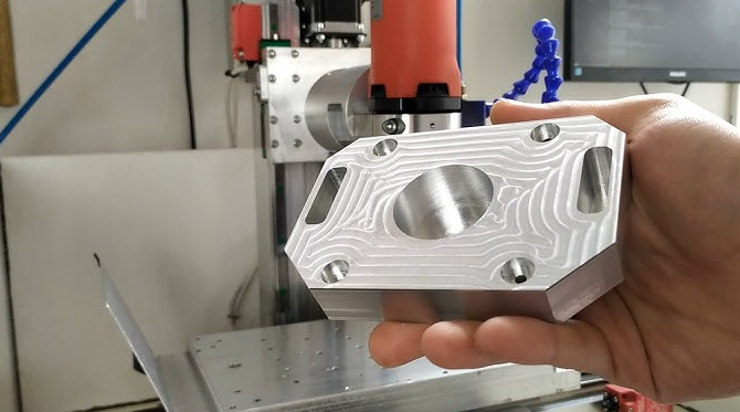
 Małe partie, wysokie standardy. Nasza usługa szybkiego prototypowania sprawia, że weryfikacja jest szybsza i łatwiejsza —

Koszty niestandardowej obróbki aluminium ujawnione: co warsztaty nie powiedzą Wam
Co naprawdę oznacza niestandardowa obróbka aluminium
Czy kiedykolwiek zastanawiałeś się, co różni unikalny element precyzyjny od produktu dostępnego w katalogu? Odpowiedź tkwi w niestandardowej obróbce aluminium – procesie, który przekształca Twoje konkretne specyfikacje w rzeczywistość, zamiast zmuszać Cię do akceptacji gotowych rozwiązań.
Niestandardowa obróbka aluminium to produkcja części lub komponentów aluminiowych zgodnie ze specyficznymi projektami i wymaganiami przy użyciu technologii sterowania numerycznego komputerowego (CNC), zapewniając wysoką precyzję, dużą powtarzalność oraz możliwość wytwarzania elementów o skomplikowanych kształtach.
W przeciwieństwie do masowej produkcji, podczas której tysiące identycznych części opuszcza linie montażowe, w tym podejściu Twoje indywidualne wymagania stają się centrum każdej decyzji. Nie Ty dopasowujesz swojego projektu do dostępnych opcji – proces produkcyjny dopasowuje się do Ciebie.
Co czyni frezowanie aluminium procesem dostosowanym do indywidualnych potrzeb
Słowo „dostosowany” ma tutaj rzeczywistą wagę. Gdy aluminium jest obrabiane w procesie dostosowanym do indywidualnych potrzeb, każdy parametr odzwierciedla konkretne wymagania danego projektu. Produkcja seryjna zaczyna się od ustalonego projektu i powtarza go wielokrotnie. Frezowanie dostosowane do indywidualnych potrzeb zaczyna się od Państwa pliku CAD —czyli od Państwa wizji—i buduje strategię produkcyjną wokół niego.
Różnicę tę można ująć następująco: produkcja masowa zadaje pytanie „ile sztuk potrzebujesz?”, podczas gdy frezowanie dostosowane do indywidualnych potrzeb pyta „co dokładnie potrzebujesz?”. Ta różnica ma ogromne znaczenie dla branż, które wymagają ścisłych tolerancji, specjalistycznych geometrii lub unikalnych właściwości materiału.
Elastyczność ta wykracza poza same wymiary. Projekty dostosowane do indywidualnych potrzeb obejmują:
- Unikalne cechy geometryczne niemożliwe do wykonania przy użyciu standardowych narzędzi
- Określone wymagania dotyczące stopu dopasowane do oczekiwanych właściwości użytkowych
- Specyfikacje tolerancji dostosowane do potrzeb montażu
- Wymagania dotyczące chropowatości powierzchni odpowiednie dla konkretnej aplikacji
Od surowca do precyzyjnych części
Jak więc blok aluminium przeznaczony do obróbki CNC staje się precyzyjnym elementem, którego potrzebujesz? Ta droga obejmuje kilka starannie zaplanowanych etapów.
Najpierw inżynierowie przekształcają Twój model 3D lub rysunek w instrukcje czytelne dla maszyny przy użyciu oprogramowania CAM. Te kody G informują maszynę CNC dokładnie, dokąd ma się przesunąć, z jaką prędkością wykonać cięcie oraz które narzędzia mają zostać użyte. Inżynierowie programujący planują ścieżki narzędzi i parametry cięcia z precyzją chirurgiczną.
Po zakończeniu programowania operatorzy mocują surowy materiał aluminiowy w maszynie CNC. Od tego momentu maszyna przejmuje kontrolę — wykonuje cięcia, frezowanie i wiercenie zgodnie z wcześniej zaprogramowanymi ścieżkami. Wynik? Elementy zgodne z Twoimi specyfikacjami z dokładnością do poziomu mikronów.
Dlaczego aluminium zdobyło pozycję materiału pierwszego wyboru w zastosowaniach CNC z użyciem aluminium? Powody gromadzą się bardzo szybko. Jest lekkie, a jednocześnie niezwykle wytrzymałym materiałem — co ma kluczowe znaczenie tam, gdzie liczy się oszczędność masy bez kompromisów w zakresie integralności konstrukcyjnej. Doskonała przewodność cieplna i elektryczna czyni je idealnym wyborem na chłodnice oraz obudowy urządzeń elektronicznych. Naturalna warstwa tlenku zapewnia odporność na korozję. A być może najważniejsze z punktu widzenia obróbki – plastyczność aluminium pozwala na cięcie wysoką prędkością, co skraca czas i obniża koszty energetyczne w porównaniu z cięższymi metalami.
Te zalety wyjaśniają, dlaczego branże od lotnictwa i astronautyki po urządzenia medyczne polegają na obróbce aluminium w swoich najbardziej wymagających zastosowaniach. Gdy projekt wymaga precyzji, dostosowania do indywidualnych potrzeb oraz wysokiej wydajności materiału działających razem, ta metoda oferuje to, czego standardowa produkcja po prostu nie jest w stanie zapewnić.
Wybór odpowiedniego stopu aluminium do Twojego projektu
Oto prawda, której większość warsztatów nie zdradzi dobrowolnie: wybór stopu aluminium może wpłynąć na koszty projektu o 30–50% jeszcze przed wykonaniem pierwszego cięcia. Wybranie niewłaściwej gatunkowości oznacza płacenie za wytrzymałość, której nie potrzebujesz — albo, co gorsza, odkrycie w trakcie produkcji, że materiał nie nadaje się do danego zastosowania. Zrozumienie właściwości aluminium w obróbce skrawaniem oznacza znajomość tego, który stop zapewnia dokładnie to, czego wymaga Twój projekt — ani więcej, ani mniej.
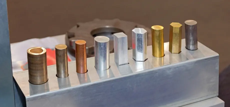
Cztery podstawowe stopy aluminium stosowane w produkcji niestandardowych wyrobów to 6061, 7075, 2024 i 5052. Każdy z nich oferuje charakterystyczne zalety, a dobranie odpowiedniej gatunkowości do konkretnych wymagań decyduje o opłacalności projektu lub o drogich błędach.
Dobór stopów w zależności od wymagań projektu
Wyobraź sobie dobór stopu jako rozwiązanie zagadki składającej się z czterech kluczowych elementów: wymagania dotyczące wytrzymałości, ekspozycja na czynniki środowiskowe, złożoność obróbki skrawaniem oraz ograniczenia budżetowe. Jeśli te cztery aspekty zostaną prawidłowo zsynchronizowane, wykonywane części z aluminium będą działać dokładnie tak, jak zakłada projekt.
6061 Aluminium zyskuje swoją reputację jako niezawodny materiał do zadań ciężkich i to z dobrych powodów. Ten stop krzemowo-magnezowy oferuje doskonałą spawalność, wiarygodną odporność na korozję oraz czysto się przecina przy minimalnym zużyciu narzędzi. Gdy inżynierowie nie mają specyficznych wymagań projektowych, które zmuszałyby ich do wyboru innego materiału, 6061 staje się domyślnym wyborem. Można go znaleźć w elementach samochodowych, komponentach morskich, sprzęcie budowlanym oraz obudowach elektronicznych — zasadniczo wszędzie tam, gdzie ważniejsza jest wszechstronność niż ekstremalne osiągi.
7075 Aluminium wkracza wtedy, gdy wytrzymałość staje się bezwzględnie konieczna. Ten dominowany cynkiem stop dorównuje stali pod względem wytrzymałości na rozciąganie, zachowując przy tym korzyść wagową aluminium. Komponenty lotnicze, zastosowania wojskowe, ramy rowerów oraz sprzęt do wspinaczki skalnej opierają się na wyjątkowym stosunku wytrzymałości do masy 7075. Jednak ta wydajność wiąże się z pewnymi kompromisami: ograniczoną spawalnością oraz zwiększoną podatnością na korozję w porównaniu z innymi gatunkami.
aluminium 2024 wyróżnia się tam, gdzie odporność na zmęczenie decyduje o sukcesie lub porażce. Składający się głównie z miedzi ten stop wytrzymuje powtarzające się cykle obciążeń, które w końcu spowodowałyby pęknięcie materiałów o niższej jakości. Konstrukcje lotnicze, pojazdy wojskowe oraz elementy konstrukcyjne poddawane wysokim naprężeniom korzystają z trwałości stopu 2024 pod wpływem obciążeń cyklicznych. Podobnie jak stop 7075, oferuje on nieco mniejszą odporność na korozję w zamian za lepsze właściwości mechaniczne.
5052 aluminium dominuje tam, gdzie warunki środowiskowe decydują o wyborze materiału. Zawartość magnezu zapewnia wyjątkową odporność na korozję, szczególnie wobec wody morskiej – co czyni go idealnym wyborem dla elementów wyposażenia morskiego, przewodów paliwowych oraz cystern. Choć nie jest tak wytrzymał ani łatwy w obróbce jak stop 6061, jego odporność w surowych warunkach usprawiedliwia tę kompromisową decyzję w odpowiednich zastosowaniach.
Kompromisy między wytrzymałością a obrabialnością
Oto czego rzadko wyjaśniają tabele porównawcze: silniejsze stopy zwykle wymagają od procesu obróbki skrawaniem większych nakładów. Zrozumienie tych kompromisów pozwala uniknąć kosztownych niespodzianek podczas obróbki aluminium.
| Stop | Wykorzystanie maszynowe | Wytrzymałość na rozciąganie | Odporność na korozję | Koszt względny | Najlepsze zastosowania |
|---|---|---|---|---|---|
| 6061 | Doskonały | Dobre | Dobre | $ | Prototypy, uchwyty, ogólne części konstrukcyjne |
| 7075 | Dobry (wymaga ostrożnego obchodzenia się) | Doskonały | Sprawiedliwe | $$-$$$ | Przemysł lotniczy i kosmiczny, elementy poddawane wysokim naprężeniom, ramy dronów |
| 2024 | Dobry (wymaga doświadczonego obchodzenia się) | Doskonały | Sprawiedliwe | $$ | Elementy wyposażenia samolotów, konstrukcje krytyczne pod względem zmęczeniowym |
| 5052 | Umiarkowany | Umiarkowany | Doskonały | $ | Sprzęt morski, obudowy, układy paliwowe |
Złożoność obróbki stopu ma bezpośredni wpływ na wycenę. Stop 6061 pozwala na wyższe prędkości posuwu i powoduje minimalne zużycie narzędzi, co przekłada się na krótsze czasy cyklu oraz niższe koszty obróbki. W porównaniu do niego stop 7075 wymaga niższych prędkości skrawania, częstszej wymiany narzędzi oraz starannej planacji torów narzędzia, aby uniknąć problemów związanych z naprężeniami. Cena materiału może być o 30–50% wyższa niż cena stopu 6061, ale różnica w czasie obróbki jeszcze bardziej powiększa tę lukę.
Zgodność z procesami wykańczania powierzchni stanowi kolejny aspekt wymagający uwagi. Stop 6061 doskonale anoduje się, co redukuje złożoność obróbki końcowej. Natomiast stopy 2024 i 7075 często wymagają dodatkowych zabiegów powierzchniowych zapewniających odpowiednią ochronę przed korozją — kolejny czynnik kosztowy, który nie pojawia się w początkowej wycenie materiału.
Kiedy wysokiej klasy stopy aluminium uzasadniają swoje koszty
Brzmi to drogo? Czasem tak wysokiej klasy części z aluminium mają doskonały sens finansowy . Kluczem jest zrozumienie, kiedy wyższe początkowe koszty zapobiegają poważniejszym problemom w dalszej części cyklu życia produktu.
Wybierz stop 7075, gdy awaria konstrukcyjna jest niedopuszczalna. W przypadku elementów złącznych do zastosowań lotniczych, komponentów do wyścigów wydajnościowych lub dowolnych zastosowań, w których stosunek wytrzymałości do masy ma bezpośredni wpływ na bezpieczeństwo lub funkcjonalność, wyższa cena się opłaca. Awaria uchwytu kosztuje nieskończenie więcej niż różnica cenowa w stosunku do tańszej odmiany stopu.
Wybierz stop 2024, gdy Twoje części są narażone na miliony cykli obciążenia. Konstrukcje skrzydeł, nośne ramy oraz komponenty podlegające powtarzającym się obciążeniom korzystają z odporności stopu 2024 na zmęczenie materiału. Dodatkowy koszt znacznie wydłuża okres użytkowania, redukując częstotliwość wymiany i całkowite koszty posiadania.
Zainwestuj w stop 5052, gdy narażenie na czynniki środowiskowe zagraża trwałości. Środowiska morskie, przetwarzanie chemiczne oraz zewnętrzne instalacje elektryczne niszczą w czasie gorsze stopy. Wyższy początkowy koszt zakupu materiału odpornego na korozję jest opłacalniejszy niż wielokrotne wymienianie uszkodzonych elementów.
Wybierz standardowo stop 6061, gdy żadne z tych specjalnych wymagań nie ma zastosowania. W przypadku prototypowania, uchwytów ogólnego przeznaczenia, oprzyrządowania do zautomatyzowanych procesów oraz większości niestandardowych projektów stop 6061 zapewnia optymalny balans między wydajnością, obrabialnością a kosztem. Jego łatwa dostępność skraca również czas realizacji zamówienia i ułatwia pozyskiwanie materiału – czynniki te przyczyniają się do dodatkowych oszczędności w całym cyklu produkcji.
Zrozumienie charakterystyki tych stopów przed złożeniem ofert pomaga precyzyjnie określić rzeczywiste potrzeby. Nadmiernie zaawansowane rozwiązania powodują niepotrzebne wydatki, podczas gdy niedostateczne specyfikacje prowadzą do awarii. Prawidłowy wybór stopu zaczyna się od rzetelnej oceny rzeczywistych wymagań, a nie od założeń co do tego, co mogłoby być potrzebne.
Parametry frezowania CNC, dzięki którym aluminium błyszczy
Wybrałeś idealny stop. Teraz pojawia się pytanie, które większość warsztatów pomija: w jaki sposób frezarki CNC rzeczywiście cięły aluminium inaczej niż inne metale? Odpowiedź na to pytanie decyduje o tym, czy Twoje elementy będą miały lustrzane wykończenie, czy też będą pokryte wadami – oraz o tym, czy płacisz za wydajną produkcję, czy za nieefektywne przeróbki.
Frezowanie CNC z użyciem aluminium wymaga zupełnie innego podejścia niż frezowanie stali lub tytanu. Jeśli dobrane zostaną odpowiednie parametry, aluminium staje się jednym z najbardziej satysfakcjonujących materiałów do obróbki. Jeśli jednak parametry będą błędne, na każdym etapie pracy będziesz zmagać się z lepkim osadzaniem się materiału, niską jakością powierzchni i przedwczesnym zużyciem narzędzi.
Podstawy prędkości obrotowej i posuwu dla aluminium
Oto co zaskakuje wielu początkujących: operacje frezowania CNC z użyciem aluminium przeprowadza się znacznie szybciej niż w przypadku stali. Podczas gdy dla stali wymagane mogą być prędkości obrotowe wrzeciona w zakresie 500–1500 obr/min, aluminium najlepiej obrabia się przy prędkościach 3000–6000 obr/min lub wyższych. Chodzi tu nie tylko o wydajność – chodzi przede wszystkim o zachowanie się materiału.
Podczas frezowania aluminium z wyższymi prędkościami materiał ścinany jest czysto, a nie rozrywany. Przy niższych prędkościach aluminium ulega odkształceniom przed krawędzią skrawającą, co powoduje tzw. zachowanie „lepkie”, generujące liczne problemy. Prędkość jest w tym przypadku Waszym sojusznikiem.
Liczby jasno opowiadają tę historię:
- Prędkość wału: 3 000–6 000 obr./min (w porównaniu do 500–1 500 obr./min dla stali)
- Prędkość cięcia: 600–1 000 stóp na minutę (powierzchniowo)
- Posuw: 0,002–0,005 cala na ząbek
- Głębokość skrawania: 0,04–0,10 cala na przejście
Wartości posuwu wymagają starannego doboru. Zbyt agresywny posuw spowoduje przeciążenie narzędzia, prowadząc do jego przedwczesnego zużycia oraz gorszej jakości powierzchni. Zbyt ostrożny posuw oznacza właściwie tarcie zamiast cięcia — generowanie ciepła bez efektywnego usuwania materiału. Optymalna wartość zależy od konkretnego stopu aluminium, zastosowanego narzędzi i sztywności maszyny; jednak rozpoczęcie pracy w podanych zakresach zapewnia wiarygodny punkt wyjścia dla frezarek CNC przeznaczonych do obróbki aluminium.
Przy obliczaniu prędkości obrotowej wrzeciona stosuje się wzór n = (Cs × 1000) / (π × d) pomaga określić optymalne obroty na minutę (RPM) na podstawie pożądanej prędkości skrawania i średnicy obrabianego przedmiotu. W przypadku frezowanych części aluminiowych prawidłowe zastosowanie tego obliczenia stanowi kluczową różnicę między profesjonalnymi a amatorskimi wynikami.
Skuteczne usuwanie wiórków i odprowadzanie ciepła
Zapytaj dowolnego doświadczonego tokarza lub frezera, jaka jest największa trudność przy obróbce aluminium — wspomnie o kontroli wiórków jeszcze zanim ukończysz pytanie. „Lepka” natura aluminium powoduje, że wiórki przyczepiają się do krawędzi tnących, tworząc zjawisko tzw. brzegu narastającego (BUE — built-up edge), które pogarsza jakość powierzchni i przyspiesza zużycie narzędzi.
Brzeg narastający powstaje wtedy, gdy aluminium przyczepia się do powierzchni tnącej narzędzia podczas operacji CNC na aluminium. Każde kolejne przejście przesuwa następnie ten nagromadzony materiał po powierzchni obrabianego przedmiotu, pozostawiając rysy, niestabilne wymiary oraz chropowatą powierzchnię. Zapobieganie powstawaniu brzegu narastającego wymaga podejścia wieloaspektowego.
Poprawne zastosowanie środka chłodzącego stanowi pierwszą linię obrony. Środki chłodzące rozpuszczalne w wodzie, zaprojektowane specjalnie do obróbki aluminium, pełnią podwójną funkcję: obniżają temperaturę cięcia oraz smarują strefę styku narzędzia z wiórkami, zapobiegając ich przywieraniu. Według Seco Tools , utrzymanie odpowiedniej koncentracji środka chłodzącego oraz wprowadzenie planu konserwacji bezpośrednio wpływa na trwałość narzędzi i spójność jakości wykonywanych części.
Zarządzanie ciepłem stanowi ciekawy paradoks w przypadku aluminium. Materiał ten przewodzi ciepło bardzo szybko – mniej więcej pięć razy szybciej niż stal – co wydaje się korzystne. Jednak ta wysoka przewodność oznacza, że ciepło generowane w strefie cięcia rozprasza się szybko w obrabianym elemencie zamiast być odprowadzane razem z wiórkami. Nadmierna akumulacja ciepła powoduje niestabilność wymiarową: część rozszerza się podczas obróbki, a następnie kurczy się po jej zakończeniu.
Skuteczne strategie radzenia sobie z tymi wyzwaniami obejmują:
- Dostarczanie środka chłodzącego pod wysokim ciśnieniem: Nalewa strefę cięcia, usuwając wiórki zanim zdążą one ponownie przyczepić się do powierzchni
- Chłodzenie przez wrzeciono: Dostarcza smaru bezpośrednio do krawędzi tnącej na frezarce CNC do obróbki aluminium
- Systemy dmuchaw powietrznych: Usuwa wióry z kieszeni i głębokich cech, gdzie chłodzenie trudno sięga
- Zoptymalizowane obciążenie ostrza: Utrzymanie wystarczającej ilości usuwanego materiału na ząbek zapewnia, że wióry odprowadzają ciepło zamiast pozostawiać je w obrabianym elemencie
Kluczowe spostrzeżenie? Wióry powinny opuszczać strefę cięcia w postaci małych, dobrze uformowanych spiral — nie długich, przewijających się wstążek ani sklejonych grudek. Wióry w postaci wstążek wskazują na zbyt niskie prędkości posuwu, natomiast grudkowanie sygnalizuje niewystarczające chłodzenie lub nieodpowiednie prędkości obrotowe.
Wybór narzędzi zapobiegający problemom
Ustawienia parametrów mają znaczenie jedynie wtedy, gdy narzędzia są w stanie je wykonać. Obróbka aluminium wymaga ostrych, specjalnie zaprojektowanych narzędzi tnących — tępe lub nieodpowiednie narzędzia przekształcają nawet doskonałe parametry w przeciętne rezultaty.
Narzędzia węglikowe dominują w obróbce aluminium z dobrych powodów. Zachowują ostrze dłużej niż stal szybkotnąca (HSS), wytrzymują wyższe prędkości wrzeciona i zapewniają lepszą jakość powierzchni. W przypadku profesjonalnej obróbki aluminium narzędzia węglikowe nie są opcjonalne – są niezbędne.
Geometria narzędzia ma ogromne znaczenie przy obróbce aluminium. Wysokie kąty helisy – zwykle 45 stopni lub więcej – poprawiają usuwanie wiórków, bardziej intensywnie wyciągając materiał z rowka cięcia. Polerowane kształty rowków zmniejszają tarcie i zapobiegają gromadzeniu się wiórków w rowkach, co jest typowym przyczyną uszkodzenia narzędzi podczas głębokich operacji frezowania kieszonek.
Powłoki dodają kolejnego poziomu wydajności. Powłoki PVD (osadzania warstw metodą osadzania z fazy gazowej) takie jak TiAlN zapewniają doskonałą stabilność termiczną i odporność na zużycie. Niektórzy producenci oferują obecnie specjalne powłoki do aluminium i metali nieżelaznych (ANF), zaprojektowane specjalnie w celu zapobiegania tworzeniu się narośli przez zmniejszenie tarcia na granicy narzędzie–wiórek.
Frezy końcowe z dwoma i trzema ostrzami pozostają standardem do obróbki aluminium. Mniejsza liczba ostrzy oznacza większe kieszenie wiórowe – przestrzenie między krawędziami tnącymi – zapewniające więcej miejsca na odprowadzanie wiórów. Narzędzia czteroostrzowe mogą być stosowane przy operacjach wykańczających, gdzie obciążenie wiórem jest minimalne, ale istnieje ryzyko zatkania podczas intensywnych operacji frezowania ścisłego.
Jedna często pomijana szczegółowa kwestia: uchwyty narzędzi są tak samo ważne jak same narzędzia. Uchwyty frezarskie, uchwyty koletkowe wysokiej precyzji oraz uchwyty termiczne zapewniają stałą biegunowość i sztywność. Wysokiej jakości frez końcowy zamocowany w zużytym uchwycie będzie działał gorzej niż przeciętne narzędzie zamocowane w precyzyjnym uchwycie. Wdrożenie zapobiegawczego programu konserwacji uchwytów chroni inwestycję w wysokiej klasy narzędzia.
Zrozumienie tych podstaw obróbki skrawaniem pozwala na bardziej krytyczną ocenę ofert. Gdy warsztaty opisują swoje możliwości w zakresie obróbki aluminium, rozpoznasz, czy stosują optymalne parametry, czy jedynie traktują aluminium jak każdy inny metal – różnica ta przejawia się zarówno w jakości końcowej części, jak i w wysokości faktury.
Wytyczne projektowe redukujące koszty i poprawiające jakość
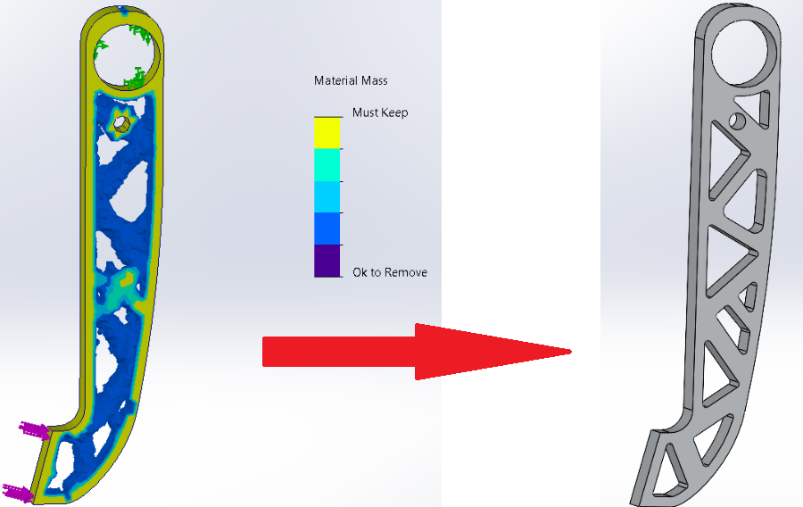
Oto sekret, który większość ofert na obróbkę skrawaniem nie ujawnia: największym czynnikiem wpływającym na koszty nie jest wybór materiału ani nawet specyfikacje dopuszczalnych odchyłek wymiarowych – lecz właśnie projekt samej części. Niestosowne decyzje geometryczne podjęte na etapie modelowania CAD mogą podwoić lub potroić czas obróbki jeszcze przed rozpoczęciem produkcji. Dobrą wiadomością jest to, że celowe modyfikacje projektu często pozwalają obniżyć koszty o 30–50%, a przy tym rzeczywiście poprawiają jakość wykonywanej części.
Zasady projektowania z myślą o wykonalności (DFM) przekształcają frezowanie CNC aluminium z procesu rozwiązywania problemów w zoptymalizowany proces produkcyjny. Gdy projekt uwzględnia rzeczywiste ograniczenia produkcyjne, każdy kolejny etap przebiega płynniej – od przygotowania oferty po końcową kontrolę jakości.
Zasady dotyczące grubości ścianek zapobiegające uszkodzeniom
Wyobraź sobie frezowanie precyzyjnego elementu w ściance tak cienkiej, że ugięła się pod wpływem nacisku narzędzia. Wymiar, który określiłeś, staje się fizycznie niemożliwy do osiągnięcia – nie z powodu ograniczeń maszyny, lecz z powodu odkształcenia materiału pod wpływem siły skrawania. Taka sytuacja występuje regularnie w warsztatach otrzymujących części zaprojektowane bez odpowiedniego uwzględnienia wymogów technologicznych.
Grubość ścianki decyduje bezpośrednio o tolerancjach, jakie można realistycznie osiągnąć. Zgodnie z wytycznymi produkcyjnymi firmy okdor, zachowanie minimalnej grubości ścianki wynoszącej 3 mm dla części aluminiowych wymagających tolerancji ±0,001 cala zapobiega problemom związанныm z ugięciem materiału, które uniemożliwiają osiągnięcie wymaganej precyzji. Oto, jak grubość ścianki wpływa na osiągalną dokładność:
- Ściany o grubości poniżej 1 mm: Oczekiwana dokładność wynosi maksymalnie ±0,010 cala — cechy precyzyjne stają się niewykonalne
- Ściany o grubości 1–2 mm: Rzeczywista dokładność spada do ±0,005 cala i wymaga starannego zabezpieczenia przedmiotu obrabianego
- Ściany o grubości 2–3 mm: dokładność ±0,002 cala jest osiągalna przy zastosowaniu odpowiednich strategii podparcia
- Ściany o grubości 3 mm i więcej: Pełna zdolność do osiągnięcia dokładności ±0,001 cala w zastosowaniach frezowania precyzyjnego z aluminium
Zasady fizyki są proste: siły skrawania powodują momenty zginające, których wartość rośnie wykładniczo wraz ze zmniejszaniem się grubości ściany. Ściana aluminiowa o grubości 1 mm ulega odkształceniu około 8 razy większemu niż ściana o grubości 3 mm przy identycznych obciążeniach skrawających. Żadna umiejętność operatora ani jakość wyposażenia nie potrafi pokonać tego podstawowego zjawiska.
Co zrobić, jeśli projekt wymaga cienkich ścian? Istnieje kilka strategii wspomagających:
- Dodaj lokalnych przełożonych: Zgrub tylko obszary wokół elementów o ścisłych tolerancjach
- Wewnętrzne żeberka: Trójkątne podpory z tyłu cienkich przekrojów zwiększają sztywność bez widocznych zmian
- Przeniesienie cech: Przenieś wymagania dotyczące dokładności do naturalnie grubszych obszarów
- Dostosowanie tolerancji: Zaakceptuj fakt, że cienkie ścianki ograniczają osiągalną dokładność
Zanim prześlesz rysunki, przeanalizuj swój model, mierząc grubość ścianek w pobliżu każdego miejsca ze ścisłą tolerancją. Jeśli znajdziesz cienkie obszary podporowe, albo zgrub je, albo złagód tolerancję — nie marnuj pieniędzy na osiąganie niemożliwej precyzji w przypadku każdego części z aluminium wykonanej frezowaniem.
Promienie zaokrągleń narożników i zależności między geometrią narzędzia a kształtami elementów
Każde frezarka CNC ma kształt cylindryczny. Ten prosty fakt tworzy rzeczywistość, którą często pomijają projektanci: narożniki wewnętrzne zawsze będą miały promień odpowiadający promieniowi narzędzia. Ostry narożnik wewnętrzny nie istnieje w standardowym frezowaniu — jego wykonanie wymaga operacji wtórnych, takich jak EDM, co znacznie zwiększa koszty.
Zrozumienie tej zależności pozwala na mądrzejsze projektowanie od samego początku. Zgodnie z Przewodnikiem inżynierskim Wevolvera , promień zaokrąglenia wewnętrznego (fillet) powinien wynosić przynajmniej 25–35% głębokości wnęki, aby uwzględnić geometrię narzędzia i zapobiec jego uszkodzeniu.
Obliczenia wyglądają następująco: przy frezowaniu kieszeni o głębokości 12 mm należy dodać w narożnikach promień 5 mm (lub większy). Pozwala to standardowemu frezowi czołowemu o średnicy 8 mm (czyli promieniu 4 mm) na swobodne frezowanie bez gwałtownych zmian kierunku, które obciążają narzędzie. Mniejsze promienie wymuszają użycie mniejszych narzędzi, co oznacza:
- Wielokrotne przejścia przy obniżonych prędkościach
- Dłuższy czas cyklu i wyższe koszty
- Wyższe ryzyko złamania narzędzia
- Gorszą jakość wykończenia powierzchni w narożnikach
Jak wygląda sytuacja z projektami wymagającymi kątów prostych — na przykład gdy prostokątny element musi dokładnie zmieścić się w gnieździe? Zamiast wymuszać niemożliwie małe promienie zaokrągleń naroży, zastosuj sprytne rozwiązanie: dodaj wycięcia (undercuty) w każdym narożu. Takie podejście umożliwia dopasowanie prostokątnych części współpracujących, zachowując przy tym możliwość obróbki naroży standardowymi narzędziami.
Stosunki głębokości do szerokości kieszeni i wpadek podlegają podobnym ograniczeniom. Standardowe frezy czołowe najlepiej sprawdzają się przy frezowaniu wnęk o głębokości do 2–3 razy większej niż ich średnica. Frez o średnicy ø12 mm czysto frezuje na głębokość 25 mm. Powyżej tej wartości rośnie ugięcie narzędzia, pogarsza się dokładność, a konieczne staje się stosowanie specjalnych narzędzi o dużym zasięgu — wszystko to zwiększa koszt oferty na usługi niestandardowej obróbki CNC.
W przypadku głębokich cech konstrukcyjnych rozważ zastosowanie kieszeni stopniowanych. Zamiast pojedynczego kanału o głębokości 20 mm i szerokości 6 mm zaprojektuj dwie kieszonki o głębokości 10 mm każda, połączone obszarem przejściowym o większych wymiarach. Funkcja pozostaje identyczna, natomiast koszt obróbki znacznie spada.
Projektowanie z uwzględnieniem osiągalnych tolerancji
Specyfikacja tolerancji może być najważniejszym czynnikiem wpływającym na koszty, który pozostaje pod Twoją kontrolą. Zgodnie z danymi branżowymi dotyczącymi kosztów, zmiana tolerancji z ±0,0005 cala na ±0,005 cala może obniżyć koszty obróbki mechanicznej o 300–500%. Niemniej jednak inżynierowie rutynowo określają ścisłe tolerancje dla każdej wymiaru „dla pewności”.
Takie podejście skutkuje negatywnymi konsekwencjami finansowymi. Każda ścisła tolerancja wymaga wolniejszych prędkości skrawania, dodatkowego czasu na inspekcję oraz często wielokrotnych weryfikacji pomiarowych. Tolerancję ±0,001 cala należy stosować wyłącznie tam, gdzie funkcjonalność produktu rzeczywiście tego wymaga — np. w przypadku miejsc osadzania łożysk, pasowań wałów lub powierzchni uszczelniających. Dla elementów niemających znaczenia funkcjonalnego, takich jak otwory montażowe czy powierzchnie zewnętrzne, wystarczają standardowe tolerancje ±0,005 cala.
Zastosuj tę ramę decyzyjną przed określeniem jakiejkolwiek ścisłej tolerancji:
- Waleczki obrotowe/łożyska: ±0,001 cala uzasadnione — zapobiega zaklinowaniu i zużyciu
- Statyczne powierzchnie uszczelniające: ±0,002 cala odpowiednie — zapewnia odpowiednie dociskanie uszczelki
- Piny lub kołki do wyrównania: ±0,003 cala wystarczające — zapewnia prawidłową pozycję
- Standardowe otwory montażowe: ±0,005 cala – wystarczające; elementy mocujące nie wymagają większej dokładności
- Elementy przeznaczone do zapewnienia luzu: ±0,010 cala – dopuszczalne; wystarczy zapewnić luzy
Sprawdź wybór tolerancji, zadając sobie pytanie: „Co ulegnie uszkodzeniu, jeśli ta wartość zmieni się o ±0,005 cala?”. Jeśli nic się nie uszkadza, zastosuj standardową tolerancję i zaoszczędź budżet na precyzję dla cech, które rzeczywiście jej wymagają.
Nakładanie się tolerancji w złożonych zespołach wprowadza kolejny aspekt do rozważenia. Gdy wiele części łączy się ze sobą, poszczególne tolerancje sumują się. W zespole pięciu części, z których każda ma tolerancję ±0,002 cala, całkowita suma odchyłek może osiągnąć ±0,010 cala na końcowym elemencie styku. Poprawny dobór punktów odniesienia oraz zastosowanie systemu GD&T zgodnie ze standardem ASME Y14.5 pomaga kontrolować takie łańcuchy tolerancji, jednak zrozumienie tej zasady pozwala uniknąć nieprzyjemnych niespodzianek podczas montażu.
Przed ostatecznym przygotowaniem rysunków do produkcji elementów z aluminium należy wykonać poniższą listę kontrolną DFM:
- Grubość ścian przekracza 3 mm w pobliżu wszystkich cech precyzyjnych
- Promienie zaokrągleń wewnętrznych wynoszą co najmniej 1/3 głębokości kieszeni
- Głębokość kieszeni nie przekracza trzykrotnej szerokości (maksymalnie czterokrotna)
- Ścisłe допусki występują tylko w wymiarach krytycznych z funkcjonalnego punktu widzenia
- Do wszystkich otworów stosowane są standardowe średnice wiertła
- Długość gwintu ograniczona do 2–2,5 średnicy nominalnej
- Wysokie cechy zachowują stosunek wysokości do szerokości poniżej 4:1
- Zapewniono dostęp narzędzi do wszystkich cech wewnętrznych
Zajęcie się tymi elementami jeszcze przed złożeniem ofert cenowych świadczy o zaawansowaniu inżynierskim — a zwykle przekłada się na niższe ceny. Firmy obróbkowe rozpoznają projekty, które można efektywnie frezować CNC z aluminium, w przeciwieństwie do tych, które wymagają ciągłego rozwiązywania problemów na linii produkcyjnej. Inwestycja w analizę zaprojektowania pod kątem wykonalności (DFM) przynosi korzyści przez cały cykl produkcji i poza nim.
Zrozumienie dopuszczalnych odchyłek w obróbce frezarskiej aluminium
Zoptymalizowałeś swój projekt pod kątem możliwości produkcyjnych. Teraz pojawia się pytanie, które ma bezpośredni wpływ na Twój budżet: jak ścisłe tolerancje są naprawdę potrzebne? Różnica między określeniem tolerancji ±0,05 mm a ±0,01 mm może zwiększyć koszty obróbki mechanicznej kilkukrotnie — mimo to wielu inżynierów domyślnie wybiera specyfikacje „precyzyjne”, nie rozumiejąc, co determinuje te koszty ani czy bardziej ścisłe wartości rzeczywiście poprawiają ich produkt.
Poprawne określanie tolerancji odróżnia świadomego zakupującego od tych, którzy płacą zbyt dużo. Zrozumienie tego, co jest osiągalne, co jest drogie, a co jest rzeczywiście konieczne, pozwala na określenie parametrów części aluminiowych wykonanych metodą frezowania tak, aby spełniały one wymagania funkcjonalne, bez marnowania budżetu na niepotrzebną precyzję.
Standardowe i precyzyjne wymagania dotyczące dopuszczalnych odchyleń
Jakich rzeczywistych wyników można oczekiwać od części aluminiowych wykonanych metodą frezowania? Odpowiedź zależy w dużej mierze od rodzaju operacji oraz możliwości maszyny. Zgodnie z przewodnikami branżowymi dotyczącymi tolerancji, typowe zakresy tolerancji zależą od rodzaju cechy:
| Typ cechy | Tolerancja standardowa | Dokładność tolerancji | Wpływ na koszty |
|---|---|---|---|
| Frezowanie ogólne | ±0,05 mm | ±0,01 mm | zwiększenie o 2–3 razy |
| Operacje tokarskie | ±0,025 mm | ±0.005 mm | 2-krotne zwiększenie |
| Średnice otworów | ±0,05 mm | ±0,02 mm | 1,5–2-krotny wzrost |
| Pozycje otworów | ±0,10 mm | ±0,025 mm | zwiększenie o 2–3 razy |
| Roughness surface | 63 µin (1,6 µm) | 32 µin (0,8 µm) | Zmienna |
Zwróć uwagę, jak toczenie zwykle zapewnia ścislsze допусki niż frezowanie? Symetria obrotowa zmniejsza wiele źródeł odkształceń, które utrudniają obróbkę części pryzmatycznych. Gdy projekt pozwala na to, cechy cylindryczne na maszynie CNC do aluminium zawsze zapewniają bardziej precyzyjne wymiary niż złożone geometrie frezowane trójosiowo.
Większość projektów CNC z aluminium mieści się wygodnie w ogólnych standardach tolerancji ISO 2768-m (średnia dokładność) lub ISO 2768-f (wysoka dokładność). Te standardy stosuje się automatycznie do wymiarów bez wyraźnie określonych допусków, zapewniając rozsądną dokładność bez konieczności ponoszenia dodatkowych kosztów. Ścislsze specyfikacje rezerwuj wyłącznie dla tych wymiarów, gdzie funkcjonalność rzeczywiście tego wymaga.
Czynniki wpływające na zdolność do osiągania określonych допусków
Dlaczego jedna firma jest w stanie zapewnić допусk ±0,01 mm, podczas gdy inna dopiero osiąga ±0,05 mm? Kilka czynników łącznie decyduje o osiągalnej precyzji – a ich zrozumienie pozwala realistycznie ocenić deklaracje dostawców.
Geometria Części bezpośrednio ogranicza to, co jest możliwe. Małe promienie wewnętrzne wymagają małych średnic narzędzi, które łatwiej uginają się i zmniejszają dokładność. Głębokie wgłębienia wymagają wydłużonych narzędzi, co nasila drgania. Cienkie ściany uginają się pod wpływem sił skrawania. Zanim określi się ścisłe допусki, należy ocenić, czy geometria elementu fizycznie na nie pozwala.
Stabilność oprzyrządowania często decyduje o powodzeniu lub porażce prac precyzyjnych. Zgodnie z opinią specjalistów ds. dopuszczalnych odchyłek przy obróbce skrawaniem , nieprawidłowe zamocowanie powoduje drgania i odkształcenia detalu, których nie da się skompensować nawet najbardziej starannym programowaniem. Specjalne oprzyrządowanie, płyty próżniowe oraz miękkie imadła pomagają zachować prawidłową pozycję – szczególnie przy cienkościennych elementach aluminiowych wykonanych metodą CNC, które są podatne na odkształcenia.
Rozszerzenie termiczne stwarza wyzwania charakterystyczne dla aluminium. Materiał ten rozszerza się o około 23 µm na metr przy wzroście temperatury o jeden stopień Celsjusza. Część o długości 500 mm, wykonana w ciepłej warsztatowej hali, może mieć pomiar różniący się o 0,02 mm po sprawdzeniu w klimatyzowanym pomieszczeniu. Poważne prace wymagające wysokiej precyzji wymagają środowisk kontrolowanych pod względem temperatury – zwykle 20 °C ± 1 °C – zarówno podczas obróbki, jak i pomiaru.
Kalibracja Maszyny ustala punkt odniesienia. Współczesne centra CNC osiągają dokładność pozycjonowania w zakresie ±0,005 mm, ale wyłącznie przy regularnej kalibracji z aktywną kompensacją termiczną. Zakłady monitorujące temperaturę maszyn i przestrzegające harmonogramów kalibracji osiągają znacznie bardziej spójną kontrolę tolerancji niż te, które traktują precyzję jako element wtórny.
Stan narzędzi zmniejsza zdolność do utrzymania tolerancji wraz z upływem czasu. Zmatowione lub zużyte narzędzia zwiększają ciśnienie tnące i generują więcej ciepła, co prowadzi do powiększenia zmienności wymiarowej. Regularna wymiana narzędzi oraz zoptymalizowane ścieżki narzędzia zmniejszają ugięcia i poprawiają powtarzalność w całym cyklu produkcji.
Inteligentne określanie tolerancji
Oto niezręczna prawda: ścisłe допусki są droższe, ponieważ wymagają niższych prędkości, dodatkowych ustawień, doskonalonego narzędziowania oraz wydłużonego czasu kontroli. Zgodnie z analizą kosztów produkcji przesunięcie od standardowych do precyzyjnych допусków zazwyczaj podwaja lub potraja koszt pojedynczej części.
Inteligentne określanie допусków zaczyna się od funkcji, a nie od założeń. Zadaj sobie pytania:
- Czy ta powierzchnia styku wymaga precyzyjnego połączenia wciskowego, czy wystarczy luźne połączenie?
- Czy problemy montażowe pojawią się, jeśli ten wymiar będzie się różnił o ±0,05 mm zamiast o ±0,01 mm?
- Czy ten element jest kontrolowany wizualnie, czy też styka się z innym elementem o wysokiej precyzji?
W przypadku zespołów aluminiowych wykonanych metodą CNC norma GD&T (Geometric Dimensioning and Tolerancing – geometryczne wymiary i допусki) oferuje potężne narzędzia wykraczające poza proste допусki typu plus/minus. Zgodnie z materiałami inżynierskimi firmy Protolabs, GD&T kontroluje relacje między cechami — takie jak rzeczywista pozycja, płaskość, cylindryczność, współśrodkowość i prostopadłość — których nie da się określić za pomocą dwustronnych допусków.
Zwróć uwagę na płaskość: powierzchnia frezowana może spełniać tolerancje wymiarowe, ale lekko ulec odkształceniu z powodu naprężeń wewnętrznych lub sił docisku podczas obróbki. Wymóg płaskości zgodnie z normą GD&T określa dwie równoległe płaszczyzny, pomiędzy którymi musi się znajdować dana powierzchnia, wykrywając w ten sposób problemy, których nie ujawnią zwykłe pomiary wymiarowe.
Weryfikacja pomiarowa wprowadza kolejny poziom kosztów. Proste wymiary można szybko zweryfikować za pomocą suwmiarek lub mikrometrów. Do sprawdzania skomplikowanych geometrii oraz cech określonych zgodnie z normą GD&T wymagane są maszyny pomiarowe współrzędnościowe (CMM) – drogie urządzenia wymagające wykwalifikowanych operatorów. Należy uwzględnić złożoność kontroli pomiarowej przy podejmowaniu decyzji dotyczących tolerancji.
Jedno ostatnie, często pomijane zagadnienie: różne metody pomiarowe dają nieco odmienne wyniki. Ustalenie jasnych punktów odniesienia pomiarowego oraz spójnych procedur pomiarowych na etapie wczesnym zapobiega sporom po dostarczeniu części. Protokoły weryfikacji należy omówić już w trakcie przygotowywania oferty – nie po zakończeniu produkcji.
Podsumowując? Określ dopuszczalne odchylenia na podstawie wymagań funkcjonalnych, a nie odbieranej jakości. Standardowe допuszczalne odchylenia doskonale spełniają większość zastosowań. Zastrzegaj precyzyjne wymagania tolerancyjne wyłącznie dla cech, których wydajność rzeczywiście zależy od ścislejszego kontrolowania odchylenia. Twoje budżet – oraz Twój partner produkcyjny – będą Ci za to wdzięczni.
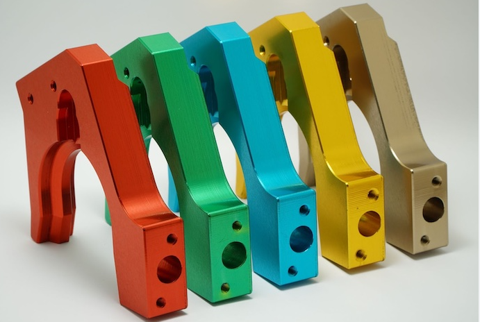
Opcje wykańczania powierzchni niestandardowych elementów z aluminium
Twoja praca frezowania precyzyjnego aluminium została ukończona – ale element wciąż nie jest gotowy. Obróbka powierzchni przekształca surowe, wyfrezowane elementy z aluminium z komponentów funkcjonalnych w gotowe wyroby przygotowane do zastosowań wymagających wysokich standardów. Jednak większość zakupujących traktuje obróbkę końcową jako kwestię drugorzędną, przegapiając tym samym szanse na jednoczesne poprawienie trwałości, wyglądu i wydajności.
Zrozumienie dostępnych opcji wykończenia przed ostatecznym zatwierdzeniem projektów pozwala zaoszczędzić pieniądze i uniknąć niespodzianek związanych z niezgodnością elementów. Wybrane obróbka powierzchniowa wpływa bezpośrednio na wybór stopu, wymagania dotyczące dopuszczalnych odchyłek oraz przeznaczenie produktu – dlatego wykończenie powierzchni stanowi decyzję strategiczną, a nie jedynie estetyczną.
Rodzaje anodowania i ich zastosowania
Anodowanie dominuje w procesach wykańczania aluminium z dobrych powodów: tworzy ochronną warstwę tlenku, która jest faktycznie częścią samego metalu, a nie powłoką naniesioną na jego powierzchnię. Ten proces elektrochemiczny zwiększa grubość naturalnej warstwy tlenku aluminium z kilku nanometrów do dziesiątek lub setek mikrometrów – co znacznie poprawia odporność na korozję oraz właściwości tribologiczne.
Jednak wiele osób nie zdaje sobie sprawy z tego, że „anodowanie” nie jest jednym, jednorazowym procesem. Dwa główne typy – Typ II i Typ III – służą zupełnie innym celom, a wybór niewłaściwego typu wiąże się z marnowaniem środków lub niespełnieniem oczekiwanych parametrów.
Anodowanie typu II (nazywane również anodowaniem dekoracyjnym lub siarkowym) tworzy warstwy tlenku o typowej grubości 5–25 mikrometrów. Ta obróbka wyróżnia się w zakresie:
- Dodawania intensywnych, trwałych kolorów poprzez barwienie w trakcie procesu
- Zapewniania solidnej odporności na korozję w warunkach użytkowanych wewnątrz pomieszczeń oraz przy umiarkowanym użytkowaniu na zewnątrz
- Tworzenia powierzchni nieprzewodzących prądu elektrycznego do obudów elektronicznych
- Zachowywania ścisłych tolerancji wymiarowych (dodaje jedynie 0,5–1 mil na każdą powierzchnię)
Anodowanie typu II doskonale sprawdza się w przypadku aluminium stopu 6061, które anoduje się jednorodnie i charakteryzuje się doskonałą zdolnością pochłaniania barwników. Można je spotkać w urządzeniach elektronicznych dla konsumentów, elementach wyposażenia architektonicznego oraz komponentach dekoracyjnych, gdzie ważna jest zarówno estetyka, jak i ochrona.
Anodowanie typu III (anodowanie twardym pokryciem) tworzy warstwy tlenku o grubości 25–100+ mikrometrów. Zgodnie ze specjalistami z firmy Rapid Axis, ten proces generuje wyjątkowo grube warstwy tlenku, znacznie zwiększające twardość oraz odporność na zużycie. Anodowanie typu III zapewnia:
- Ekstremalną odporność na zużycie dla części narażonych na ścieranie oraz naprężenia mechaniczne
- Wysoka odporność termiczna do zastosowań w wysokich temperaturach
- Powierzchnie o niskim współczynniku tarcia, które zmniejszają konieczność konserwacji ruchomych elementów
- Wydajna ochrona przed korozją w trudnych warunkach środowiskowych
Jaka jest cena tego rozwiązania? Typ III wymaga dodatkowej ilości materiału — zwykle 2–3 mil na powierzchnię — co należy uwzględnić przy obliczeniach dopuszczalnych odchyłek. Części wymagające precyzyjnych końcowych wymiarów często muszą być frezowane z niedomiarem, aby skompensować tę warstwę. Ponadto oferuje on ograniczoną gamę kolorów w porównaniu do typu II oraz kosztuje około 2–3 razy więcej.
Wybierz typ III dla komponentów hydraulicznych, sprzętu wojskowego, ciężkiego sprzętu maszynowego oraz wszelkich zastosowań, w których części wykonane na frezarce do aluminium są narażone na powtarzające się obciążenia mechaniczne.
Opcje wykończenia poza anodowaniem
Anodowanie nie zawsze jest odpowiednim rozwiązaniem. Kilka alternatywnych metod obróbki spełnia konkretne wymagania, których anodowanie nie potrafi — lub nie powinno — spełniać.
Powieka przekształcająca chromaty (nazywane również chem film lub Alodine) rozwiązuje problem powodowany anodowaniem: przewodność elektryczną. Zgodnie z przewodnikami przemysłowymi dotyczącymi obróbki powierzchniowej, w przeciwieństwie do anodowania, które jest nieprzewodzące, chem film zachowuje przewodność elektryczną aluminium, jednocześnie zapewniając odporność na korozję. Dlatego jest niezbędny w przypadku:
- Powierzchni uziemiających
- Zastosowania ekranowania EMI/RFI
- Elementów wymagających przyczepności farby lub powłoki proszkowej
- Części o tak ścisłych tolerancjach wymiarowych, że anodowanie nie jest możliwe
Warstwa chem film jest niezwykle cienka — praktycznie nie powoduje żadnych zmian wymiarowych — co czyni ją odpowiednią dla wyrobów aluminiowych o ścisłych wymaganiach tolerancyjnych. Przemysły lotniczy, obronny i elektroniczny w dużym stopniu polegają na tej metodzie obróbki powierzchni.
Malowanie proszkowe zapewnia niezrównaną wszechstranność pod względem koloru i ochrony. Suchy proszek nanoszony elektrostatycznie i utwardzany w temperaturze tworzy wytrzymałą, jednolitą powłokę odporną na zadrapania, skruszenia oraz blaknięcie pod wpływem promieni UV. Zasadniczo każdy kolor lub faktura osiągalna za pomocą farby staje się możliwa do uzyskania również metodą natrysku proszkowego – od matowej po wysokiej połyskowości, od gładkiej po teksturującej.
Natrysk proszkowy szczególnie nadaje się do:
- Sprzętu zewnętrznego narażonego na działanie promieni UV i warunków atmosferycznych
- Produktów konsumenckich wymagających określonych kolorów marki
- Sprzętu przemysłowego wymagającego odporności chemicznej
- Zastosowań, w których ważna jest zarówno estetyka, jak i trwałość
Dodatkowy korzyść środowiskowa: natrysk proszkowy nie zawiera lotnych związków organicznych (VOC), co czyni go bardziej przyjaznym dla środowiska rozwiązaniem niż farby ciekłe.
Wyrzucanie z wiązki tworzy jednolite powierzchnie matowe, które maskują ślady obróbki skrawaniem oraz odciski palców. Zgodnie z danymi referencyjnymi dotyczącymi wykończenia powierzchni, piaskowanie kulkami zapewnia średnie chropowatość wynoszącą około 42 Ra (mikrocali), dając spójny wygląd satynowy. Różne rozmiary i materiały kulek pozwalają uzyskać różne tekstury:
| Stopień piaskowania | Tekstura powierzchni | Typowe zastosowania |
|---|---|---|
| Stopień 1 (bardzo drobny) | Gładka, minimalna tekstura | Sprzęt medyczny, elementy kosmetyczne |
| Klasa 2 (Delikatna) | Niska tekstura | Elementy do przemysłu lotniczego i kosmicznego, precyzyjne przyrządy pomiarowe |
| Stopień 3 (średni) | Umiarkowana tekstura | Części samochodowe, obudowy maszyn |
| Stopień 4 (gruby) | Powierzchnia chropowata | Komponenty morskie, sprzęt przemysłowy |
Piaskowanie kulkowe często poprzedza anodowanie lub powlekanie proszkowe, tworząc idealną powierzchnię do jednolitego przyczepiania się kolejnych powłok.
Tłoczenie i usuwanie zaciepek usuwa ostre krawędzie i zaciepki, które nieuchronnie pozostawia obróbka skrawająca. Tłoczenie wibracyjne za pomocą środków ceramicznych lub plastikowych zaokrągla krawędzie, usuwa zaciepki i zapewnia jednolitą teksturę powierzchni nawet na złożonych kształtach geometrycznych. W przypadku projektów z aluminium zawierających wiele krawędzi i elementów wewnętrznych tłoczenie zapewnia opłacalne wykończenie powierzchni, którego nie da się osiągnąć ekonomicznie metodą ręcznego usuwania zaciepek.
Dobieranie powłok do wymagań funkcjonalnych
Wybór odpowiedniego wykończenia wymaga zrównoważenia wielu czynników: wymagań dotyczących trwałości, wyglądu, ograniczeń budżetowych oraz zgodności z danym stopem aluminium. Porównanie to pomoże w dokonaniu wyboru spośród dostępnych opcji:
| Typ wykończenia | Trwałość | Koszt względny | Wygląd | Najlepsze zastosowania |
|---|---|---|---|---|
| Anodowanie typu II | Dobre | $ | Dostępne kolory, wygląd metaliczny | Elektronika użytkowa, architektura, zastosowania dekoracyjne |
| Anodowanie typu III | Doskonały | $$-$$$ | Ograniczona paleta kolorów, matowy wygląd | Przemysł wojskowy, układy hydrauliczne, ciężka technika |
| Powłoka chromatowa | Umiarkowany | $ | Złoty/jasny, iryzujący | Uziemienie elektryczne, przygotowanie powierzchni do malowania, przemysł lotniczy i kosmiczny |
| Malowanie proszkowe | Bardzo dobrze. | $$ | Dowolny kolor, od matowego do połyskującego | Sprzęt zewnętrzny, produkty konsumenckie, motocykle i samochody |
| Wyrzucanie z wiązki | Niski (wyłącznie estetyczny) | $ | Jednolity matowy połysk satynowy | Przygotowanie powierzchni, jednolitość estetyczna |
| Niklowanie bezzapadowe | Doskonały | $$$ | Jasny metaliczny | Zastosowania morskie, przemysł naftowy i gazowy, surowe warunki środowiskowe |
Wybór stopu ma bezpośredni wpływ na kompatybilność wykończenia – czynnik często pomijany, dopóki nie pojawią się problemy. Relacja ma znaczenie:
- 6061:Doskonale anoduje się z doskonałą zdolnością do barwienia; idealny do aplikacji kolorowych typu II
- 7075:Wystarczająco dobrze anoduje się, ale z lekko szarawym odcieniem; lepszy do typu III niż do prac dekoracyjnych
- 2024:Niedobry materiał do anodowania ze względu na zawartość miedzi; często wymaga stosowania powłoki chemicznej lub malowania
- 5052:Dobrze reaguje na anodowanie; doskonała podstawa do nanoszenia powłoki proszkowej w zastosowaniach morskich
Określ swoje wymagania dotyczące wykończenia już na etapie przygotowywania oferty — nie po zakończeniu obróbki skrawaniem. Doświadczony producent wyrobów z aluminium może doradzić, czy wybrany stop i rodzaj wykończenia zapewnią oczekiwane efekty, co pozwoli uniknąć kosztownej przeróbki lub rozczarowujących rezultatów.
Jedna ostatnia uwaga: proces wykończenia wydłuża czas realizacji. Anodowanie zwykle trwa 3–5 dni, natomiast nanoszenie powłoki proszkowej — 2–4 dni; specjalistyczne metody wykończenia mogą jeszcze dłużej wydłużać harmonogram. Należy uwzględnić te czasy w planie projektu, szczególnie w przypadku łączenia wielu etapów wykończenia — np. piaskowania, następnie anodowania, a na końcu znakowania laserowego.
Dzięki strategicznym decyzjom dotyczącym wykończenia powierzchni inwestycja w obróbkę aluminium zapewnia komponenty, które działają zgodnie z przeznaczeniem i prezentują się profesjonalnie. Następne kluczowe pytanie? Zrozumienie czynników wpływających na koszty widoczne w ofertach — oraz miejsc, w których często kryją się ukryte wydatki.
Jakie czynniki wpływają na koszty niestandardowej obróbki aluminium
Otrzymałeś/aś ofertę — a podana kwota wydaje się wyższa niż oczekiwano. Co ją determinuje? Frustrujące jest to, że większość warsztatów nie przedstawia szczegółowego rozkładu kosztów, za które płacisz. Zrozumienie prawdziwych czynników wpływających na cenę niestandardowych elementów z aluminium pozwala podejmować świadome decyzje, strategicznie zoptymalizować konstrukcje oraz rozróżnić, kiedy cena rzeczywiście odzwierciedla złożoność projektu, a kiedy po prostu płacisz zbyt dużo.
Zgodnie z analizą kosztów produkcji RapidDirect podstawowy wzór można uprościć w następujący sposób: Całkowity koszt = Koszt materiału + (Czas obróbki × Stawka maszynowa) + Koszt przygotowania maszyny + Koszt wykończenia. Każdy z tych składników oferuje możliwości optymalizacji — o ile wie się, gdzie szukać.
Czynniki złożoności wpływające na cenę
Czas obróbki dominuje w ofercie cenowej, a złożoność określa czas obróbki. Ale co dokładnie czyni detal „złożonym” z punktu widzenia ceny?
Oto główne czynniki wpływające na koszty, uporządkowane według typowego stopnia wpływu:
- Liczba wymaganych ustawień: Każdorazowe ponowne umieszczanie detalu w maszynie wiąże się z dodatkowym czasem pracy operatora, czasem programowania oraz ryzykiem błędów wyrównania
- Elementy wymagające ścisłych tolerancji: Specyfikacje precyzyjne wymagają niższych prędkości skrawania, dodatkowego czasu na kontrolę jakości oraz często specjalistycznego narzędzi
- Cienkie ścianki wymagające ostrożnej obróbki: Elementy podatne na odkształcenia wymuszają obniżenie prędkości posuwu i czasem stosowanie niestandardowych uchwytników
- Głębokie wgłębienia i wnęki: Dłuższe narzędzia, wielokrotne przejścia na różną głębokość oraz trudności z usuwaniem wiórków powodują wydłużenie czasu cyklu
- Wymagania dotyczące jakości powierzchni: Wysokiej klasy wykończenia wymagają dodatkowych przejść, drobniejszych narzędzi lub operacji obróbki końcowej
- Małe promienie wewnętrzne: Bardzo małe promienie narożników zmuszają do stosowania mniejszych narzędzi, które skrawają wolniej i szybciej się zużywają
Zgodnie z podziałem kosztów obróbki firmy Komacut, złożone konstrukcje zawierające otwory, wycięcia, szczegółowe elementy oraz ścisłe допусki wymagają niższych prędkości obróbki w celu zapewnienia dokładności — co wydłuża czas obróbki oraz zwiększa prawdopodobieństwo częstych wymian narzędzi. Każda wymiana narzędzia dodaje kilka minut; przy setkach części aluminiowych wykonanych na frezarkach CNC te minuty sumują się do znacznych różnic kosztowych.
Rodzaj maszyny również ma znaczenie. Frezarka 3-osiowa kosztuje około 35–50 USD za godzinę, podczas gdy sprzęt 5-osiowy — niezbędny do obróbki złożonych geometrii — kosztuje 75–120 USD za godzinę. Gdy projekt zmusza do zastosowania frezarki 5-osiowej, mimo że tę samą pracę można było wykonać na prostszej maszynie, płacisz dwukrotnie więcej za każdą minutę czasu skrawania.
Ekonomia skali w niestandardowej obróbce skrawaniem
Dlaczego pojedynczy prototyp kosztuje 500 USD, podczas gdy każda część w serii 100 sztuk kosztuje zaledwie 50 USD? Odpowiedź tkwi w kosztach stałych, które nie skalują się wraz z ilością.
Koszty przygotowania obejmują programowanie CAM, tworzenie uchwytów, przygotowanie narzędzi oraz weryfikację pierwszego egzemplarza. Zgodnie z danymi branżowymi koszt przygotowania w wysokości 300 USD zwiększa cenę zamówienia jednosztucznego o 300 USD, ale tylko o 3 USD na sztukę w serii 100 sztuk. Ten jeden czynnik wyjaśnia, dlaczego prototypy wydają się drogie — ponosisz koszty, które w produkcji masowej rozkładane są na wiele jednostek.
Ceny objętościowe dla niestandardowo produkowanych części podlegają przewidywalnej krzywej:
- 1–5 sztuk: Najwyższy koszt jednostkowy; koszty przygotowania dominują w całkowitej cenie
- 10–50 sztuk: Znaczne obniżenie kosztu jednostkowego w miarę rozłożenia kosztów przygotowania
- 50–500 sztuk: Optymalny zakres, w którym efektywność osiąga maksimum bez ograniczeń pojemnościowych
- 500+ sztuk: Dodatkowe obniżki są możliwe, choć występują malejące korzyści krańcowe
Zakupy materiałów korzystają również z efektu skali. Zakup zapasów na 100 części często uprawnia do cen hurtowych, do których zamówienia pojedynczych sztuk nie dają dostępu. Niektóre warsztaty przekazują te oszczędności klientom; inne wliczają je do swojej marży. Zapytanie o szczegółowy podział kosztów materiałów pozwala określić, które z tych podejść stosuje dostawca.
Niestandardowe części maszynowe w małych ilościach pozostają z natury drogie – tej rzeczywistości nie da się uniknąć. Jednak konsolidacja zamówień, łączenie podobnych części w jedno ustawienie obróbkowe lub synchronizacja produkcji prototypów z partiami produkcyjnymi umożliwia wykorzystanie niektórych korzyści wynikających z efektu skali nawet przy niewielkich ilościach.
Ukryte koszty decyzji projektowych
Oto czego większość ofert nie podaje wyraźnie: decyzje projektowe podjęte tygodnie przed przygotowaniem oferty często determinują aż 80% kosztów produkcji. Zgodnie z badaniami nad optymalizacją procesów produkcyjnych decyzje podejmowane w fazie projektowania określają zdecydowaną większość wydatków produkcyjnych – jeszcze przed tym, jak zostanie wykonany pierwszy frez.
Te ukryte koszty narastają cicho:
Odpady materiałowe pochodzące z niestandardowych rozmiarów zapasów. Projektowanie części wymagającej nadmiernie dużych prętów, ponieważ jest ona nieco za duża dla standardowych rozmiarów zapasów, oznacza płacenie za aluminium, które zamieni się w wiórkę. Część o średnicy 105 mm wymagająca pręta o średnicy 150 mm powoduje marnowanie 30 % zakupionego materiału. Zgodnie z Przewodnikiem APF Villeneuve dotyczącym redukcji kosztów , projektowanie z uwzględnieniem powszechnie stosowanych rozmiarów zapasów bezpośrednio zmniejsza ilość odpadów i obniża ofertową cenę.
Specyfikacje tolerancji surowsze niż to konieczne. Przejście od ogólnych tolerancji do specyfikacji precyzyjnych może zwiększyć czas obróbki mechanicznej 2–3-krotnie. Inżynierowie jednak rutynowo stosują surowe wymagania tolerancyjne do cech niemających znaczenia funkcjonalnego, kierując się raczej nawykiem niż rzeczywistą potrzebą. Każda niepotrzebnie surowa tolerancja przekłada się bezpośrednio na wyższą cenę niestandardowych części CNC.
Wymagania dotyczące wykończenia niezgodne z funkcją. Określenie anodowania twardego typu III, gdy anodowanie typu II zapewnia wystarczającą ochronę, powoduje 2–3-krotne zwiększenie kosztów wykończenia. Wymaganie lustrzanego polerowania powierzchni wewnętrznych, których nikt nie widzi, generuje dodatkowy nakład pracy bez jakiegokolwiek korzyści funkcjonalnych.
Cechy wymagające specjalistycznego sprzętu. Wklęsłości, bardzo głębokie otwory lub złożone geometrie wewnętrzne mogą wymusić zastosowanie elektroerozji (EDM), obróbki na frezarkach 5-osowych lub operacji wtórnych. Zgodnie ze specjalistami ds. optymalizacji konstrukcji unikanie głębokich wnęk oraz minimalizowanie potrzeby stosowania specjalistycznych narzędzi bezpośrednio obniża koszty produkcji i czas realizacji.
Jakie jest rozwiązanie? Zaangażuj swojego partnera ds. obróbki mechanicznej jak najwcześniej — już w trakcie projektowania, a nie po jego finalizacji. Doświadczone zakłady potrafią zidentyfikować cechy powodujące wzrost kosztów i zaproponować alternatywne rozwiązania, które zachowują funkcjonalność produktu przy jednoczesnym obniżeniu jego ceny. 10-minutowa rozmowa przeglądowa dotycząca projektu pozwala często zaoszczędzić tysiące złotych w kosztach produkcji.
Dzięki tej przejrzystości kosztów możesz teraz krytycznie oceniać oferty. Gdy ceny wydają się zbyt wysokie, zadaj konkretnie pytania: które cechy powodują złożoność? Jakie tolerancje byłyby wymagane, aby obniżyć koszty? Czy istnieją modyfikacje projektu, które zachowują funkcjonalność, ale poprawiają łatwość produkcji? Firmy produkcyjne, które otwarcie odpowiadają na te pytania, stają się partnerami w optymalizacji kosztów — dokładnie taką relację chcesz budować przy produkcji niestandardowych elementów z aluminium.
Czasy realizacji i rzeczywistości planowania produkcji
Zoptymalizowałeś/aś swój projekt, wybrałeś/aś odpowiedni stop aluminium oraz otrzymałeś/aś konkurencyjną ofertę. Teraz pojawia się pytanie, które często decyduje o sukcesie lub niepowodzeniu projektu: kiedy dokładnie Twoje elementy zostaną dostarczone? Oczekiwania dotyczące czasów realizacji stanowią jeden z najbardziej niezrozumianych aspektów niestandardowego frezowania aluminium — a różnica między tym, co zakupujący zakładają, a tym, co rzeczywiście oferują firmy produkcyjne, powoduje więcej opóźnień projektowych niż jakiekolwiek wyzwania techniczne.
Zrozumienie realistycznych harmonogramów pozwala skutecznie planować, precyzyjnie komunikować się ze zainteresowanymi stronami oraz identyfikować dostawców rzeczywiście zdolnych do spełnienia ustalonego harmonogramu, w przeciwieństwie do tych, którzy dają obietnice, których nie będą w stanie dotrzymać.
Harmonogramy prototypowania vs. produkcji
To, co zaskakuje wielu zakupujących po raz pierwszy, to fakt, że części prototypowe często wymagają więcej czasu na jednostkę niż serie produkcyjne — mimo że chodzi „tylko o jeden egzemplarz”. Wydaje się to sprzeczne z logiką, dopóki nie zrozumie się, co tak naprawdę dzieje się w tle.
Zgodnie ze specjalistami CNC zajmującymi się prototypowaniem, typowe harmonogramy prototypowania przedstawiają się następująco:
- Proste części z aluminium: 24–48 godzin od zatwierdzenia projektu
- Średnia złożoność: 3-5 dni roboczych
- Złożone części wymagające wielu ustawień: 5-7 dni roboczych
- Części wymagające kontroli za pomocą maszyny pomiarowej CMM: Dodaj 1–2 dni na weryfikację
Dlaczego tak długo trwa realizacja pojedynczej części? W fazie prototypowania praca jest wykonywana z wyprzedzeniem – koszty związane z programowaniem CAM, projektowaniem przyrządów, doborem narzędzi oraz weryfikacją pierwszego egzemplarza są rozłożone na setki sztuk w masowej produkcji. Cykl frezowania trwający 30 minut może wymagać 4–6 godzin przygotowania – czas ten nie skraca się tylko dlatego, że potrzebujesz jednej części zamiast stu.
W przypadku serii produkcyjnych równanie to ulega odwróceniu. Zgodnie z analizą harmonogramów dostaw, po zakończeniu programowania i przygotowania maszyny dostawcy usług CNC mogą produkować części w sposób ciągły. Zamówienie na 100 sztuk może potrwać jedynie o 2–3 dni dłużej niż zamówienie na 10 sztuk, ponieważ decydujący wpływ na harmonogram ma rzeczywisty czas obróbki, a nie przygotowanie.
Typowe oczekiwania dotyczące harmonogramu produkcji:
- 10–50 sztuk: 5-10 dni roboczych
- 50–200 sztuk: 10-15 dni roboczych
- 200–1000 sztuk: 15-25 dni roboczych
- 1000+ sztuk: Harmonogram zależy od przydziału dostępnych mocy produkcyjnych
Usługi szybkiej obróbki CNC mogą znacznie skrócić te harmonogramy — czasem dostarczając proste elementy już w ciągu 24 godzin. Jednak przyspieszona produkcja zwykle wiąże się z wyższymi cenami, często o 1,5–2 razy przekraczającymi standardowe stawki za priorytetowe zamówienia.
Czynniki wydłużające czas realizacji
Gdy w ofercie cenowej obiecano dostawę w ciągu dwóch tygodni, a części dotarły dopiero po czterech, co poszło nie tak? Kilka czynników zwykle przedłuża harmonogramy ponad pierwotne szacunki — a zrozumienie ich pozwala na realistyczne planowanie terminów.
Złożoność projektu i wymagania dotyczące przygotowania maszyny
Zgodnie ze specjalistami ds. terminów dostawy w obróbce CNC, elementy o cienkich ściankach lub skomplikowanych kształtach wymagają bardziej precyzyjnych ścieżek obróbki oraz potencjalnie niższych prędkości cięcia, aby uniknąć uszkodzenia delikatnych elementów konstrukcji. Każde dodatkowe ustawienie — czyli zmiana położenia elementu w celu wykonania kolejnych operacji obróbkowych — wydłuża czas przygotowania i zwiększa ryzyko opóźnień związanych z weryfikacją prawidłowego pozycjonowania.
W przypadku obróbki aluminium proces CNC nasila wpływ złożoności:
- Elementy jednoustawieniowe: Podstawowy harmonogram
- Elementy dwuustawieniowe: Dodaj 20–30% do fazy obróbki
- Trzy lub więcej ustawień: Dodaj 40–60% do fazy obróbki
- wymagania dotyczące obróbki 5-osowej: Może podwoić czas cyklu w porównaniu z obróbką 3-osową
Wymagania dotyczące dokładności wykonania i chropowatości powierzchni
Ścisłe допуски wymagają niższych prędkości skrawania oraz dodatkowego czasu na kontrolę. Zgodnie z analizą wpływu dopuszczalnych odchyłek, ścisłe допусki wymagają większej liczby przejść obróbkowych oraz precyzyjnego programowania torów narzędzia, aby zapewnić zgodność każdego elementu z dokładnymi specyfikacjami. Gładka powierzchnia końcowa często wymaga dodatkowych przejść obróbkowych przy użyciu drobniejszych narzędzi skrawających — każde takie przejście wydłuża całkowity czas cyklu.
Uwagi dotyczące dostępności materiałów
Standardowy aluminium stop 6061 znajduje się na półkach większości dostawców. Specjalistyczne stopy, takie jak 7075-T6 lub 2024-T3, mogą wymagać zamówienia — co wiąże się z dodatkowym okresem 3–7 dni przed rozpoczęciem obróbki. Usługi CNC dostępne online zwykle posiadają na stanie popularne materiały, ale mogą napotkać opóźnienia w przypadku nietypowych gatunków lub dużych bloków surowcowych. Potwierdzenie dostępności materiału w trakcie przygotowywania oferty zapobiega niespodziankom w harmonogramie.
Wymagania dotyczące wykończenia i obróbki końcowej
Obróbka stanowi jedynie część całkowitego czasu realizacji zamówienia. Obróbka powierzchniowa wprowadza własne terminy:
- Anodowanie typ II: 3–5 dodatkowych dni
- Twarde anodowanie typ III: 4–7 dodatkowych dni
- Powłoka proszkowa: 2–4 dodatkowe dni
- Konwersja chromatowa: 1–2 dodatkowe dni
Wiele etapów wykończenia powoduje kumulację tych opóźnień. Część wymagająca piaskowania, anodowania i oznakowania laserowego może dodać 7–10 dni do czasu po zakończeniu obróbki.
Objętość zamówienia i priorytet w harmonogramie
Duże zamówienia produkcyjne mają zwykle pierwszeństwo w harmonogramie w większości warsztatów — są po prostu bardziej opłacalne na godzinę czasu planowania. Małe zamówienia prototypowe mogą czekać w kolejce za większymi zamówieniami, chyba że zastosowane zostaną opłaty za przyspieszenie realizacji. Zrozumienie miejsca, jakie zajmuje Twoje zamówienie w kolejności priorytetów danego warsztatu, pozwala ustalić realistyczne oczekiwania.
Wyszukiwanie partnerów zapewniających szybkość bez kompromisów w zakresie jakości
Niektórzy dostawcy usług CNC z aluminium regularnie spełniają rygorystyczne terminy realizacji, podczas gdy inni systematycznie przekraczają umówione daty. Co wyróżnia wiarygodnych partnerów od tych, którzy tylko obiecują?
Odpowiedź tkwi w systemach, a nie tylko w sprzęcie. Warsztaty działające z certyfikowanymi systemami zarządzania jakością i statystyczną kontrolą procesów osiągają szybsze przepływy, ponieważ wykrywają problemy na wczesnym etapie — zanim wady przekształcą się w konieczność poprawek, która zakłóca harmonogramy.
Obiekty certyfikowane zgodnie z normą IATF 16949 wyraźnie ilustrują tę zasadę. Ten standard jakości motocyklowej wymaga udokumentowanych procesów, zarządzania jakością dostawców oraz protokołów ciągłego doskonalenia, które bezpośrednio przekładają się na wiarygodność dostaw. Zgodnie z badaniami nad partnerstwami produkcyjnymi wybór partnerów posiadających certyfikat ISO 9001 oraz ścisłe kontrole jakości pozwala zagwarantować spójną, wysokiej jakości produkcję, minimalizując jednocześnie opóźnienia wynikające z wad i konieczności poprawek.
W przypadku wymagających zastosowań — szczególnie w odniesieniu do komponentów łańcucha dostaw motocyklowych — certyfikaty świadczą o rzeczywistej zdolności, a nie jedynie o marketingowych deklaracjach. Usługi precyzyjnej obróbki CNC firmy Shaoyi Metal Technology ilustrują to podejście, dostarczając komponentów o wysokiej dokładności z czasem realizacji nawet do jednego dnia roboczego w zastosowaniach motocyklowych i samochodowych. Ich certyfikat IATF 16949 oraz ścisłe protokoły Statystycznej Kontroli Procesu (SPC) zapewniają niezawodną wydajność zarówno przy szybkim prototypowaniu, jak i skalowaniu produkcji masowej.
Przy ocenie potencjalnych partnerów na potrzeby projektów frezowania CNC aluminium zadaj sobie następujące pytania skupione na terminach realizacji:
- Jaki procent zamówień jest wysyłany w pierwotnie podanej dacie?
- W jaki sposób radzicie sobie z konfliktami harmonogramowymi w przypadku ograniczonej dostępności mocy produkcyjnej?
- Jakie opcje przyspieszenia realizacji są dostępne i jakie są związane z nimi koszty?
- Czy macie na stanie popularne stopy aluminium, czy wszystko musi zostać zamówione?
- Jak szybko możecie przesłać informacje zwrotne dotyczące projektowania z myślą o możliwościach produkcyjnych?
Niezbędni partnerzy dostarczają szczerych odpowiedzi — w tym przyznają się, gdy terminy nie są osiągalne. Firmy oferujące nierealistyczne terminy dostawy we wszystkich ofertach powinny budzić podejrzenia. Zgodnie z opiniami specjalistów od przejścia od prototypu do produkcji masowej, analiza czasów realizacji i historii dotrzymania terminów przez producenta pozwala lepiej planować zapasy, minimalizować opóźnienia oraz skuteczniej zarządzać przepływem środków pieniężnych.
Idealny partner produkcyjny skaluje się wraz z Twoimi potrzebami — od pojedynczych prototypów wymagających szybkiej realizacji po duże serie produkcyjne, które wymagają spójnego harmonogramowania. Niezależnie od tego, czy potrzebujesz złożonych zespołów nadwoziowych, czy niestandardowych wkładek metalowych, nawiązanie współpracy z certyfikowanymi dostawcami, którzy rozumieją wymagania jakościowe branży motocyklowej i samochodowej, zapewnia Twojemu łańcuchowi dostaw wysoką niezawodność.
Gdy realistyczne oczekiwania dotyczące harmonogramu zostały określone, a odpowiedni partnerzy zostali zidentyfikowani, pozostaje jedna kluczowa decyzja: jak ocenić i wybrać odpowiedniego partnera w zakresie obróbki skrawaniem do swoich konkretnych wymagań? Odpowiedź wykracza poza proste porównanie cen.
Wybór odpowiedniego partnera w zakresie niestandardowej obróbki skrawaniem
Opanowałeś dobór stopów, zoptymalizowałeś projekt pod kątem możliwości produkcyjnych oraz rozumiesz czynniki wpływające na koszty i harmonogram. Teraz nadszedł moment decyzji, która zadecyduje o tym, czy cała ta przygotowawcza praca przyniesie pożądane rezultaty: wybór odpowiedniego partnera świadczącego usługi obróbki aluminium. Nieodpowiedni wybór przekształca nawet doskonałe projekty w koszmary związane z dostawami, spory o jakość oraz przekroczenie budżetu. A właściwy wybór? To relacja produkcyjna, która będzie rozwijać się wraz z Twoją firmą przez wiele lat.
Oto niezręczna prawda, którą większość kupujących odkrywa zbyt późno: najniższa oferta rzadko przekłada się na najniższy całkowity koszt. Zgodnie z badaniami dotyczącymi oceny dostawców obróbki CNC wybór doskonałego dostawcy wymaga kompleksowego rozważenia wielu czynników – w tym możliwości obróbkowych, systemów kontroli jakości, doświadczenia technicznego, niezawodności terminów dostawy oraz całkowitego kosztu posiadania.
Certyfikaty mające znaczenie dla Twojej branży
Certyfikaty to nie tylko ozdoby ścienne – reprezentują one zweryfikowane systemy i procesy, które bezpośrednio wpływają na jakość Twoich części. Ale które certyfikaty mają rzeczywiście znaczenie dla Twoich niestandardowych projektów z aluminium?
ISO 9001 ustala podstawę. Zgodnie z opiniami specjalistów ds. certyfikacji jakości, certyfikat ISO 9001 gwarantuje, że firma posiada solidny proces kontroli jakości i zobowiązuje się do ciągłego doskonalenia. Ten uznany na całym świecie standard zapewnia dokumentowane procesy, kontrolowane procedury oraz spójną realizację zamówień. Dla ogólnych zastosowań przemysłowych ISO 9001 zapewnia wystarczające gwarancje kompetencji produkcyjnych.
IATF 16949 znacznie podnosi wymagania w zastosowaniach motocyklowych i samochodowych. Zgodnie z dokumentacją warsztatu maszynowego certyfikowanego przez IATF, ten standard zastępuje ISO 9001, wprowadzając wymagania specyficzne dla branży motocyklowej i samochodowej, w tym spełnianie wymagań klientów indywidualnych, protokoły zapobiegania błędom oraz śledzalność łańcucha dostaw. Jeśli Twoje części metalowe wykonane metodą frezowania trafiają do łańcuchów dostaw motocyklowych i samochodowych, certyfikacja IATF 16949 nie jest opcjonalna – jest niezbędna.
AS9100D służy zastosowaniom lotniczym i kosmicznym z dodatkowym rygorem. Zgodnie z ekspertami ds. certyfikacji lotniczych i kosmicznych, certyfikat AS9100D koncentruje się na zarządzaniu ryzykiem, zarządzaniu konfiguracją oraz śledzieniu – zapewniając, że partnerzy świadczący usługi frezowania CNC posiadają solidne procesy zapobiegawcze błędom, śledzenie zmian oraz utrzymanie kontroli jakości w całym cyklu produkcji. Komponenty lotnicze i kosmiczne wymagają tego poziomu weryfikacji.
Dopasuj certyfikaty do swoich wymagań:
- Ogólne przemysłowe: ISO 9001 minimum
- Łańcuch dostaw motocyklowy i samochodowy: Wymagany standard IATF 16949
- Komponenty lotnicze i kosmiczne: Certyfikat AS9100D jest niezbędny
- Urządzenia medyczne: Certyfikat ISO 13485
- Zastosowania wojskowe: Zgodność z przepisami ITAR oraz odpowiednie standardy jakości
Ponad certyfikaty warto zapytać o konkretne protokoły jakości. Statystyczna kontrola procesów (SPC) wskazuje na monitorowanie w czasie rzeczywistym zmiennych produkcyjnych – wykrywanie odchylenia jeszcze przed powstaniem wad. Dokumentacja pierwszej inspekcji artykułu (FAI) potwierdza, że początkowe części spełniają określone wymagania techniczne przed rozpoczęciem masowej produkcji. Możliwości pomiaru za pomocą maszyny współrzędnościowej (CMM) zapewniają weryfikację dokładności wymiarowej wykraczającą poza możliwości inspekcji ręcznej.
Ocena możliwości technicznych
Certyfikaty potwierdzają systemy; kompetencje określają, co jest rzeczywiście osiągalne. Jak odróżnić firmy, które rzeczywiście radzą sobie z Twoją złożonością, od tych, które przekraczają swoje kompetencje?
Zacznij od wyposażenia. Zgodnie z wytycznymi oceny kompetencji sprawdzenie, czy dostawca dysponuje zaawansowanymi obrabiarkami CNC, sprzętem do badań oraz wykwalifikowanym personelem technicznym, pozwala bezpośrednio ocenić, czy jest w stanie wykonać części zgodne z Twoimi wymaganiami projektowymi. Zadaj konkretne pytania:
- Jakie możliwości osi oferują Państwa maszyny (3 osie, 4 osie, 5 osi)?
- Jaka jest maksymalna objętość obrabianego przedmiotu?
- Jakie prędkości wrzeciona i posuwów są Państwo w stanie osiągnąć?
- Jakim sprzętem pomiarowym weryfikowane są Państwa tolerancje?
- Czy dysponujecie dedykowanymi możliwościami frezowania aluminium?
Doświadczenie w zakresie konkretnego zastosowania ma ogromne znaczenie. Warsztat zajmujący się obróbką komponentów samochodowych na co dzień zna dopuszczalne odchyłki, dokumentację oraz oczekiwania dotyczące jakości – świat ten znacznie różni się od świata warsztatów prototypowych. Zgodnie z badaniami oceniającymi dostawców, analiza poprzednich projektów na podstawie przypadków badawczych oraz opinii klientów pozwala uzyskać informacje na temat dotychczasowych osiągnięć partnera oraz jego zdolności do spełniania zobowiązań.
Zażądaj przykładów podobnych prac:
- Czy wcześniej obrabiano części o podobnej geometrii?
- Jakie dopuszczalne odchyłki osiągnięto w przypadku porównywalnych cech?
- Czy można zapoznać się z przypadkami badawczymi lub referencjami z podobnych zastosowań?
- Jakie wyzwania stawiały poprzednie, podobne projekty?
Możliwości wsparcia projektowego ujawniają potencjał współpracy. Zgodnie z badaniami partnerów produkcyjnych, warsztaty posiadające profesjonalne zespoły projektowe oraz oprogramowanie CAD/CAM mogą zapewnić ocenę wykonalności technologicznej, zalecenia procesowe oraz optymalizację niestandardowych części aluminiowych wykonanych metodą CNC. Partnerzy angażujący się w fazie projektowania — proponujący modyfikacje obniżające koszty przy jednoczesnym zachowaniu funkcjonalności — dostarczają większej wartości niż warsztaty ograniczające się wyłącznie do wyceny przesłanych przez klienta dokumentów.
Budowanie długoterminowych partnerstw produkcyjnych
Najlepsze relacje z usługodawcami obróbki CNC aluminium wykraczają poza pojedyncze zamówienia. Partnerzy, którzy rozumieją charakter Państwa produktów, przewidują potrzeby i rozwijają się wraz z dynamicznym wzrostem Państwa firmy, stają się przewagą konkurencyjną, a nie jedynie standardowymi dostawcami.
Jakość komunikacji w trakcie przygotowywania ofert przewiduje potencjał partnerski. Zgodnie z kryteriami oceny komunikacji, ocena skuteczności i szybkości reagowania dostawcy pozwala zagwarantować, że problemy będą rozwiązywane w terminie, a projekty będą przebiegać płynnie. Firmy serwisowe, które zadają pytania uточniające, proponują alternatywne rozwiązania oraz przedstawiają szczegółowe oferty, wykazują zaangażowanie, które utrzymuje się również w fazie produkcji.
Skalowalność ma znaczenie dla rozwijających się programów. Idealny partner jest w stanie obsłużyć potrzeby związane z prototypowaniem w krótkim czasie, a także zarządzać objętościami produkcji po dojrzeniu projektów. Zgodnie z badaniami nad mocą produkcyjną, ocena skali produkcji dostawcy, optymalizacji procesów oraz jego zdolności do obsługi szczytowych obciążeń produkcyjnych zapewnia, że zamówienia zostaną zrealizowane w uzgodnionych terminach bez opóźnień w dostawie.
W przypadku produkcji niestandardowych części w wymagających sektorach, Shaoyi Metal Technology jest przykładem modelu certyfikowanego partnera — certyfikat IATF 16949 w połączeniu z rygorystycznymi protokołami SPC zapewnia niezawodność wymaganą przez łańcuchy dostaw motocyklowe i samochodowe. Niezależnie od tego, czy potrzebujesz złożonych zespołów nadwoziowych, czy niestandardowych wkładek metalowych, ich zakład umożliwia bezproblemową skalę produkcji – od szybkiego prototypowania po masową produkcję – z czasami realizacji nawet do jednego dnia roboczego.
Użyj tej listy kontrolnej oceny przed podjęciem współpracy z dowolnym dostawcą usług frezowania aluminium:
- Certyfikaty odpowiadają wymogom branżowym (ISO 9001, IATF 16949, AS9100D)
- Możliwości wyposażenia są zgodne ze stopniem złożoności Twoich części
- Potwierdzone doświadczenie w obróbce podobnych geometrii i tolerancji
- Procesy kontroli jakości obejmują statystyczną kontrolę procesów (SPC), pomiar na współrzędnościowej maszynie pomiarowej (CMM) oraz udokumentowane procedury
- Komunikacja jest szybka, szczegółowa i proaktywna już na etapie przygotowywania oferty
- Dostępna jest pomoc projektowa w zakresie optymalizacji konstrukcji pod kątem wykonalności technologicznej
- Moc produkcyjna umożliwia skalowanie od prototypów po serie produkcyjne
- Zapis historii dostaw zweryfikowany na podstawie referencji lub opinii
- Ceny przejrzyste z wyraźnym rozdzieleniem czynników wpływających na koszty
- Polityki wsparcia posprzedażowego i gwarancji są udokumentowane
Zgodnie z najlepszymi praktykami oceny dostawców, zrozumienie polityki obsługi posprzedażowej dostawcy — w tym okresu gwarancji, usług naprawy oraz wsparcia technicznego — zapewnia szybkie i skuteczne wsparcie w przypadku wystąpienia problemów podczas użytkowania produktu.
Inwestycja w odpowiednią ocenę partnerów przynosi korzyści na całym etapie cyklu życia produktu. Indywidualne frezowanie aluminium to współpraca w zakresie precyzyjnego wytwarzania, a nie transakcja towarowa. Wybieraj partnerów, których kompetencje, certyfikaty i styl komunikacji odpowiadają Twoim wymaganiom — a także których ścieżka rozwoju jest zgodna z Twoimi celami. Poprawna relacja przekształca frezowanie z kłopotliwej operacji zakupowej w przewagę konkurencyjną, która wzrasta przy każdym pomyślnie zakończonym projekcie.
Najczęściej zadawane pytania dotyczące indywidualnego frezowania aluminium
1. Ile kosztuje frezowanie aluminium?
Koszty niestandardowej obróbki aluminium zwykle wahają się od 50 do ponad 500 USD za element, w zależności od złożoności, wymaganych dokładności i objętości zamówienia. Czas obróbki wynosi około 35–120 USD za godzinę, w zależności od typu maszyny (3 osie vs 5 osi). Koszty przygotowania maszyny (200–500 USD) mają istotny wpływ na koszt pojedynczego prototypu, ale rozkładają się na większą liczbę sztuk w przypadku seryjnej produkcji. Decyzje projektowe, takie jak ścisłe допусki, cienkie ścianki oraz konieczność wielokrotnego ustawiania detalu, mogą zwiększyć koszty 2–3-krotnie. Zamówienie 50–500 sztuk zapewnia zazwyczaj najkorzystniejszy bilans ceny jednostkowej.
2. Czy aluminium jest trudne w obróbce?
Aluminium jest w rzeczywistości jednym z najłatwiejszych metali do obróbki frezarką CNC, o ile zastosuje się odpowiednie parametry. Pozwala na prędkości wrzeciona 3–6 razy wyższe niż stal (3000–6000 obr./min) i zapewnia doskonałą jakość powierzchni. Jednak „lepkie” właściwości aluminium stwarzają trudności w kontrolowaniu wiórków — materiał może przyczepiać się do krawędzi tnących, powodując tworzenie się warstwy przyrostowej (BUE). Kluczem do sukcesu jest użycie ostrego narzędzi z węglików spiekanych, prawidłowe zastosowanie chłodziwa, zoptymalizowane posuwy oraz frezy końcowe o dużym kącie helisy zapewniające skuteczną ewakuację wiórków.
3. Ile kosztuje frezarka CNC przeznaczona do obróbki aluminium?
Maszyny CNC zdolne do obróbki aluminium mają cenę od 2500 USD dla urządzeń wejściowych typu frezarki do ponad 22 000 USD dla sprzętu przemysłowego. Jednak większość zakupujących nie zakupuje maszyn — zawiera współpracę z usługodawcami obróbki CNC. Stawki godzinowe za obróbkę aluminium metodą CNC wynoszą od 35 do 50 USD za frezowanie 3-osiowe i od 75 do 120 USD za operacje 5-osiowe. Firmy certyfikowane zgodnie ze standardem IATF 16949, takie jak Shaoyi Metal Technology, oferują precyzyjną obróbkę CNC z czasem realizacji nawet jednego dnia roboczego, całkowicie eliminując konieczność inwestycji w sprzęt.
4. Który stop aluminium jest najlepszy do obróbki CNC?
stop 6061 jest najpopularniejszym wyborem do ogólnej obróbki CNC — charakteryzuje się doskonałą obrabialnością, dobrą spawalnością, odpornością na korozję oraz najniższą ceną. Dla zastosowań lotniczych wymagających wysokiej wytrzymałości wybierz stop 7075 (choć jego cena jest o 30–50 % wyższa), dla elementów podatnych na zmęczenie, narażonych na powtarzające się cykle obciążenia — stop 2024, a dla środowisk morskich, gdzie niezbędna jest wyjątkowa odporność na korozję — stop 5052. Wybór stopu wpływa zarówno na koszt materiału, jak i na czas obróbki, dlatego należy dobrać go zgodnie z rzeczywistymi wymaganiami funkcjonalnymi.
5. Jak długo trwa obróbka niestandardowego aluminium?
Czasy realizacji różnią się znacznie w zależności od rodzaju zamówienia. Proste prototypy wysyłane są w ciągu 24–48 godzin; części o średnim stopniu złożoności wymagają 3–5 dni roboczych. Seria produkcyjna licząca 10–50 sztuk zwykle wymaga 5–10 dni roboczych, podczas gdy zamówienia na 200 i więcej sztuk potrzebują 15–25 dni. Ścisłe допусki, wiele etapów obróbki oraz wykańczanie powierzchni (anodowanie wydłuża termin realizacji o 3–7 dni) przedłużają harmonogram. Usługi szybkiej realizacji mogą przyspieszyć dostawę, ale wiążą się z wyższymi cenami. Partnerzy certyfikowani zgodnie ze standardem IATF 16949 często dostarczają komponenty motocyklowe lub samochodowe w ciągu jednego dnia roboczego.