 Małe partie, wysokie standardy. Nasza usługa szybkiego prototypowania sprawia, że weryfikacja jest szybsza i łatwiejsza —

Wykonywanie płyt aluminiowych – wyjaśnione krok po kroku: od wyboru stopu do końcowego cięcia
Co tak naprawdę oznacza wykonywanie elementów z blachy aluminiowej
Gdy słyszysz " produkcja płyty aluminiowej ," może się Pan zastanawiać, jak różni się to od pracy z cienką blachą aluminiową. Różnica ma większe znaczenie, niż można by się spodziewać — wpływa ona na wszystko: od wymaganego sprzętu po wiedzę i umiejętności niezbędne do uzyskania satysfakcjonujących rezultatów. Zrozumienie tej różnicy jest kluczowe zarówno dla inżynierów określających parametry komponentów, projektantów tworzących elementy konstrukcyjne, jak i specjalistów ds. zakupów odpowiedzialnych za pozyskiwanie materiałów.
W swojej istocie wykonywanie elementów z aluminium polega na przekształcaniu surowego materiału aluminiowego w gotowe komponenty za pomocą procesów cięcia, kształtowania, łączenia oraz wykańczania. Jednak grubość materiału decyduje o tym, w jaki sposób te procesy są wykonywane. Blacha aluminiowa reprezentuje cięższą, grubszą część skali i wymaga zastosowania specjalistycznych technik, które nie mają zastosowania przy materiałach o mniejszej grubości.
Płyta vs. blacha: kluczowa różnica w grubości
Co odróżnia aluminiową płytę od aluminiowej blachy? Odpowiedź tkwi w progach grubości, które określają klasyfikację materiału i, co za tym idzie, metody jego obróbki.
Zgodnie ze standardami branżowymi materiały o grubości przekraczającej 6,35 mm (0,25 cala) uznawane są za płyty na rynkach północnoamerykańskich. Wszystko, co jest cieńsze – aż do ok. 0,2 mm – zaliczane jest do kategorii blach. Poniżej 0,2 mm mamy do czynienia z folią aluminiową, która stanowi zupełnie inną kategorię produktu.
Dlaczego ten próg grubości ma tak duże znaczenie? Rozważmy, co dzieje się podczas cięcia aluminium (cięcia alu) grubej a cienkiej blachy:
- Wymagania sprzętowe ulegają drastycznej zmianie. Prasy, systemy cięcia oraz urządzenia do kształtowania przeznaczone do obróbki płyty grubości 1 cala znacznie różnią się od tych, które nadają się do blachy o grubości 18 cali (18 gauge).
- Zarządzanie ciepłem staje się kwestią krytyczną. Grubsze materiały pochłaniają i rozpraszają ciepło w inny sposób, co wpływa na parametry cięcia oraz głębokość spawania.
- Siły kształtujące rosną wykładniczo. Zginanie płyty o grubości pół cala wymaga znacznie większej siły (w tonach), niż kształtowanie cienkiej blachy.
- Dopuszczalne odchylenia wymiarowe i kontrola wymiarów wymagają większej uwagi. Masa i sztywność płyty wprowadzają unikalne wyzwania związane z osiąganiem precyzyjnych wymiarów.
Procesy produkcyjne różnią się również w miejscu ich powstania. Większość płyt jest wytwarzana bezpośrednio w procesie walcowania gorącego do końcowej grubości, przy użyciu surówki aluminiowej jako surowca. Produkty blachowe, w przeciwieństwie do tego, mogą podlegać walcowaniu zimnemu z płyt lub być wytwarzane bezpośrednio z odlewanych cewek aluminiowych — różnica ta wpływa na właściwości materiałowe oraz dostępność.
Podstawowe procesy obróbki grubych płytek aluminiowych
Gdy wykonujesz elementy z blachy metalowej w formie grubszych płyt, napotkasz te same podstawowe kategorie procesów co przy pracy z cienkimi blachami — jednak każdy z nich wymaga dostosowanych technik i specjalistycznej wiedzy. Poniżej przedstawiono główne metody stosowane do przetwarzania płyt aluminiowych na gotowe komponenty:
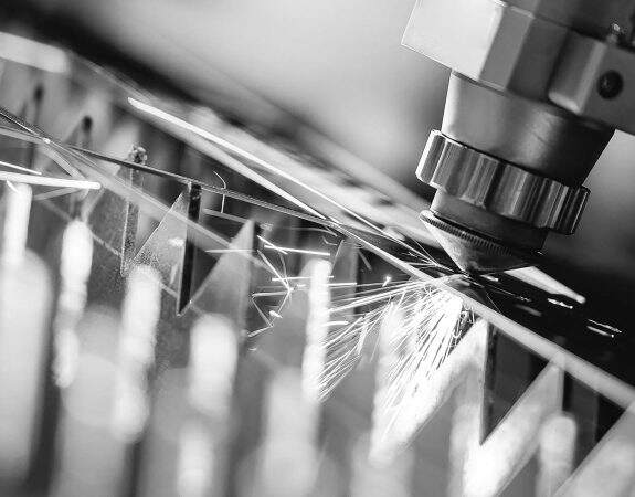
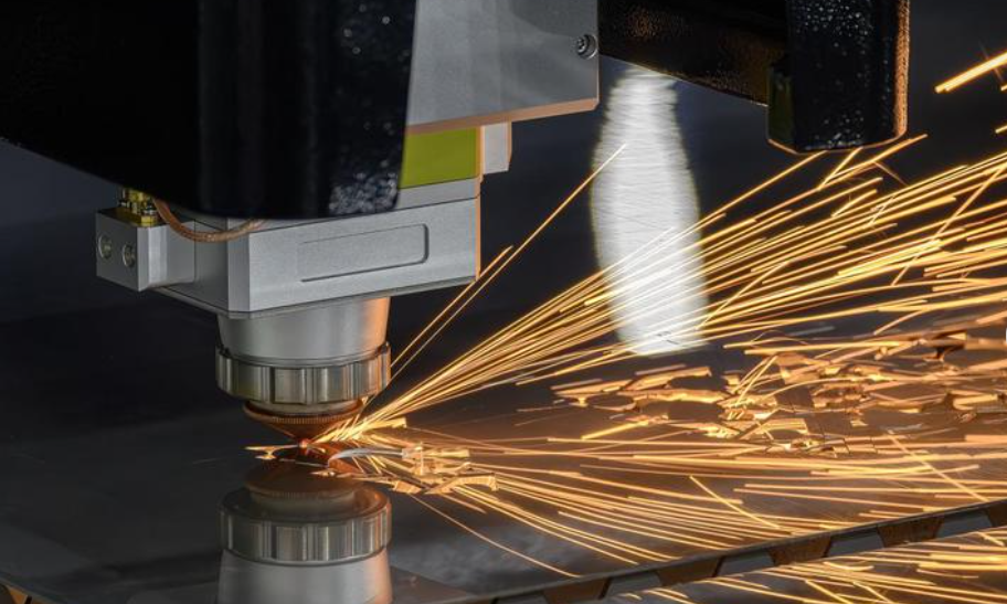
- Cięcie laserowe: Wysokomocne lasery włóknikowe zapewniają precyzyjne cięcie o doskonałej jakości krawędzi. Choć są skuteczne przy płytach o grubości do około 1 cala, wysoka przewodność cieplna aluminium stwarza unikalne wyzwania, wymagające starannego doboru parametrów. Cięcie laserem jest szczególnie polecane w przypadku złożonych kształtów i ścisłych tolerancji.
- Cięcie strumieniem wody: Ta metoda cięcia na zimno wykorzystuje strumień wody pod bardzo wysokim ciśnieniem, zmieszany z cząstkami ściernymi, umożliwiający przecinanie płyt praktycznie dowolnej grubości. Ponieważ nie powstaje strefa wpływu ciepła (HAZ), cięcie wodą z dodatkiem ścierni zachowuje właściwości materiału — co czyni je idealnym rozwiązaniem tam, gdzie kluczowe jest zachowanie integralności metalurgicznej.
- Obróbka CNC: Dla złożonych elementów trójwymiarowych, kieszeni oraz precyzyjnych otworów operacje frezowania i toczenia CNC zapewniają nieosiągalne możliwości. Ta metoda obróbki metali pozwala osiągnąć najściślejsze допуски, ale zwykle wiąże się z wyższymi kosztami oraz dłuższymi czasami cyklu.
- Kształtowanie i gięcie: Giętarki i specjalistyczne urządzenia do kształtowania przekształcają blachy w kątowniki, ceowniki oraz profile zakrzywione. Sukces zależy od zrozumienia zachowania sprężystego odskoku (springback), minimalnego promienia gięcia oraz charakterystyki kutej danej stopu aluminium.
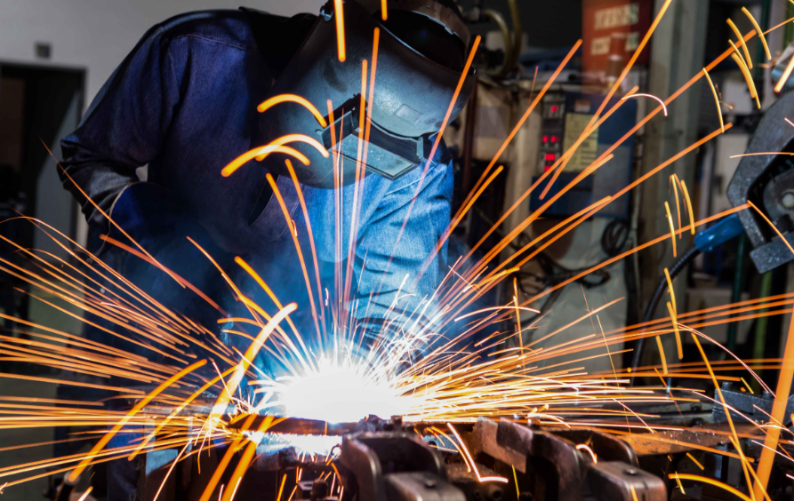
- Włókno: Spawanie blach aluminiowych wymaga zastosowania technik innych niż te stosowane przy spawaniu stali. Warstwa tlenkowa, przewodność cieplna oraz dobór materiału dodatkowego wymagają specjalistycznej wiedzy. Najczęściej stosowanymi metodami są spawanie TIG (GTAW) i MIG (GMAW); wybór konkretnej metody zależy od konstrukcji połączenia oraz wymagań aplikacyjnych.
- Wykończenie powierzchni: Od anodowania po powłokę proszkowe – metody obróbki powierzchni zwiększają odporność na korozję, właściwości tribologiczne oraz walory estetyczne. Wybór metody wykańczania zależy często zarówno od wymagań funkcjonalnych, jak i od środowiska użytkowania końcowego.
Każdy z tych procesów jest powiązany z doborem materiału oraz zamiarem projektowym. Wybrany stop aluminium wpływa na jego spawalność. Określona przez Ciebie grubość określa, które metody cięcia są stosowalne. Zrozumienie tych zależności od samego początku pozwala uniknąć kosztownych korekt w trakcie realizacji projektu i zapewnia, że komponenty z blachy aluminiowej spełnią oczekiwania dotyczące ich właściwości użytkowanych.
Dobór stopu aluminium do projektów z blachy
Wybór odpowiedniego stopu aluminium do projektu blachy to nie tylko decyzja dotycząca materiałów – to decyzja dotycząca procesu produkcji. Wybrany stop bezpośrednio wpływa na łatwość cięcia, formowania, spawania i wykańczania blach. Niewłaściwy wybór może skutkować pękniętymi wygięciami, nieszczelnymi spoinami lub problemami z korozją w przyszłości. Dokonując mądrego wyboru, zapewnisz płynny przebieg procesu produkcji od pierwszego cięcia do końcowej kontroli.
Ponieważ dostępnych jest kilkadziesiąt stopów aluminium, od czego zacząć? W przypadku większości zastosowań związanych z obróbką płyt dominują cztery stopy: 6061, 5052, 7075 oraz 3003. Każdy z nich oferuje charakterystyczne zalety i ograniczenia, które bezpośrednio wpływają na podejście produkcyjne. Zrozumienie tych różnic pozwala Ci dobrać właściwości materiału do konkretnych wymagań aplikacji .
Cztery główne stopy aluminium do prac z płytami
Przyjrzyjmy się, co czyni każdą z tych blach ze stopu aluminium wyjątkową oraz kiedy każdy z tych stopów jest odpowiedni dla Twojego projektu:
6061 Aluminium jest jednym z najbardziej uniwersalnych materiałów stosowanych do produkcji blach. Według firmy Protolabs, stop ten jest często wybierany w przypadkach, gdy wymagane jest spawanie lub lutowanie miękkie, a także ze względu na wysoką odporność na korozję we wszystkich stanach wyjściowych (tempers). Zrównoważona kombinacja umiarkowanej wytrzymałości, doskonałej spawalności oraz dobrej obrabialności czyni go pierwszym wyborem dla elementów samochodowych, rurociągów, wyposażenia morskiego, mebli oraz komponentów konstrukcyjnych. Należy jednak pamiętać, że spawanie stopu 6061 może osłabić strefę wpływu ciepła (HAZ), dlatego w zależności od wymagań dotyczących obciążeń mechanicznych w danej aplikacji może być konieczne zastosowanie niektórych zabiegów po-spawalnych.
5052 aluminium wyróżnia się w środowiskach, w których najważniejsza jest odporność na korozję. Jako Norfolk Iron & Metal uwagi: stop aluminium 5052 wyróżnia się imponującą wytrzymałością oraz wyjątkową odpornością na korozję w środowisku morskim, co czyni go pierwszym wyborem w zastosowaniach morskich, takich jak kadłuby łodzi i pomosty. Ten stop zachowuje swoją wytrzymałość nawet po spawaniu – istotna zaleta dla blach aluminiowych przeznaczonych do zbiorników paliwa, naczyń ciśnieniowych oraz zastosowań transportowych. Gęstość aluminium 5052 (około 2,68 g/cm³) zapewnia lekkość elementów przy jednoczesnej trwałości w surowych środowiskach chemicznych. Dla producentów blachy aluminiowej 5052 oferuje wysoką wytrzymałość na zmęczenie oraz bardzo dobrą obrabialność, choć jest nieco trudniejszy w kształtowaniu niż stop 3003.
7075 Aluminium reprezentuje najmocniejszy stop aluminium powszechnie dostępny do prac z blachy. Często porównywany do stali pod względem stosunku wytrzymałości do masy, ten stop jest materiałem pierwszego wyboru do elementów lotniczych, zastosowań wojskowych oraz wysokowydajnego sprzętu sportowego. Jednak ta wytrzymałość wiąże się z pewnymi kompromisami znacząco wpływającymi na procesy wytwarzania. Firmy Norfolk Iron & Metal zaznaczają, że stop 7075 charakteryzuje się niższą odpornością na korozję niż stopy 5052 lub 6061 oraz jest trudniejszy w spawaniu. Jego twardość wymaga zastosowania specjalistycznych narzędzi frezarskich, a jego kruchość w porównaniu do stopów o niższej wytrzymałości wymaga ostrożnego postępowania podczas operacji kształtowania.
aluminium serii 3003 oferta najtańszego rozwiązania dla zastosowań, w których ekstremalna wytrzymałość nie jest głównym kryterium. Stop ten zawiera mangan, który zwiększa trwałość w porównaniu do czystego glinu, zachowując przy tym doskonałą odporność na korozję oraz łatwą spawalność. Ponieważ stop 3003 nie wymaga obróbki cieplnej, pozostaje łatwy w kształtowaniu i formowaniu – dlatego jest szeroko stosowany w płytach dachowych, naczyniach kuchennych, zbiornikach paliwa oraz pojemnikach na żywność. Gdy budżet ma kluczowe znaczenie, a Twoje zastosowanie nie wymaga wysokiej wytrzymałości, blachy ze stopu aluminiowego 3003 zapewniają niezawodną wydajność w atrakcyjnej cenie.
Dopasowanie właściwości stopów do potrzeb Twojej obróbki
Wybór między tymi stopami wymaga oceny wpływu poszczególnych właściwości na konkretne procesy obróbki. Należy wziąć pod uwagę następujące kluczowe czynniki:
Spawalność określa, czy w Twoim projekcie można zastosować połączenia spawane oraz jakie środki ostrożności będą konieczne. Jeśli Twoje elementy blachowe wymagają intensywnego spawania, stopy 5052 i 3003 zapewniają najłatwiejszą drogę do przodu. Praca z aluminiem 5052 w stanie hartowanym H32 zapewnia doskonałą wytrzymałość spoin, podczas gdy dla stopu 6061 konieczne jest zwrócenie uwagi na obróbkę cieplną po spawaniu. W przypadku stopu 7075 należy zaplanować alternatywne metody łączenia, takie jak połączenia mechaniczne lub klejenie.
Wykształcalność wpływa na minimalne promienie gięcia oraz na złożoność kształtów, jakie można osiągnąć. Stany odżarzone zawsze kształtują się łatwiej niż stany utwardzone. Stopy 3003 i 5052 gięte są łatwiej niż 6061, natomiast kruchość stopu 7075 czyni agresywne operacje kształtowania ryzykownymi.
Wykorzystanie maszynowe wpływa na operacje CNC, prędkości cięcia oraz zużycie narzędzi. Stop 6061 doskonale nadaje się do obróbki skrawaniem, zapewniając doskonałą formację wiórków. Stop 7075, mimo swojej twardości, również dobrze poddaje się obróbce przy zastosowaniu odpowiednich narzędzi. Stopy 5052 i 3003 mają tendencję do tworzenia dłuższych, nitkowatych wiórków, co wymaga szczególnej uwagi przy doborze geometrii narzędzi i zastosowaniu chłodziwa.
Przewodność cieplna wpływa na parametry cięcia laserowego oraz wymagania dotyczące ciepła wprowadzanego podczas spawania. Wszystkie stopy aluminium przewodzą ciepło znacznie szybciej niż stal, jednak różnice między poszczególnymi stopami wpływają na optymalne parametry obróbki dla wybranego materiału.
| Stop | Ocena wytrzymałości | Spawalność | Wykształcalność | Odporność na korozję | Najlepsze zastosowania | Uwagi technologiczne |
|---|---|---|---|---|---|---|
| 6061 | Umiarkowane-Wysokie | Doskonały | Dobre | Bardzo dobrze. | Elementy konstrukcyjne, motocykle, przemysł morski | Może wymagać cieplnego wykończenia po spawaniu; doskonała obrabialność |
| 5052 | Umiarkowany | Doskonały | Bardzo dobrze. | Bardzo dobra (woda morska) | Przemysł morski, zbiorniki paliwa, zbiorniki ciśnieniowe | Zachowuje wytrzymałość po spawaniu; nieco trudniejszy w kształtowaniu niż stop 3003 |
| 7075 | Najwyższą | Biedny | Ograniczone | Umiarkowany | Przemysł lotniczy i kosmiczny, wojskowy, elementy poddawane wysokim naprężeniom | Wymaga specjalistycznych narzędzi; unikać spawania; rozważyć stosowanie połączeń mechanicznych |
| 3003 | Niski-średni | Doskonały | Doskonały | Bardzo dobrze. | Pokrycia dachowe, kontenery, ogólna obróbka metalowa | Najbardziej opłacalny; nie wymaga obróbki cieplnej; łatwy w obróbce |
Przy ocenie blach aluminiowych do kolejnego projektu płyty należy pamiętać, że „najlepsia” stopowa zależy w całości od wymagań aplikacyjnych. Zbiornik paliwa dla zastosowań morskich wymaga odporności na korozję stopu 5052. Uchwyt do zastosowań lotniczych wymaga wytrzymałości stopu 7075. Uniwersalna obudowa może być wykonana idealnie z taniego stopu 3003. Gdy potrzebujesz równowagi właściwości oraz doskonałych cech obróbkowych, stop 6061 często okazuje się rozsądnym wyborem.
Wybór stopu określa podstawę każdej kolejnej decyzji dotyczącej obróbki – od metody cięcia, przez parametry gięcia, po techniki łączenia. Po dobraniu odpowiedniego stopu do swojej aplikacji kolejnym kluczowym etapem jest wybór odpowiedniej grubości płyty z uwzględnieniem wymagań konstrukcyjnych i technologicznych.
Wybór odpowiedniej grubości płyty
Wybrałeś już stop – teraz pojawia się pytanie, które ma bezpośredni wpływ zarówno na właściwości użytkowe, jak i na koszty: jaka powinna być grubość płyty aluminiowej? Decyzja ta wpływa na więcej niż tylko wytrzymałość konstrukcyjną. Określa dostępne metody wytwarzania, masę wykonywanych elementów oraz ostateczną cenę gotowych części.
Wybór grubości znajduje się w punkcie przecięcia wymagań inżynieryjnych i rzeczywistości produkcyjnych. Wybranie zbyt małej grubości może spowodować ugięcie elementów pod obciążeniem lub ich przedwczesny awaryjny zakończenie eksploatacji. Wybranie zbyt dużej grubości oznacza płacenie za nadmiarowy materiał oraz ograniczenie dostępnych metod obróbki. Przeanalizujmy, jak znaleźć optymalną grubość dla Twojego zastosowania.
Wymagania obciążeniowe i obliczenia ugięć
Zanim określisz grubość, zastanów się: jakie siły będzie przenosił ten element? Zrozumienie potrzeb związanych z nośnością jest kluczowe przy podejmowaniu rozważnej decyzji dotyczącej grubości.
W zastosowaniach konstrukcyjnych inżynierowie zwykle oceniają trzy główne czynniki:
- Nośność statyczna: Jak dużą masę lub siłę musi wytrzymać płyta bez trwałej deformacji? Grubsze płyty wytrzymują większe obciążenia, ale związek ten nie jest liniowy — podwojenie grubości zwiększa nośność o więcej niż dwukrotność ze względu na większy moment bezwładności przekroju.
- Dopuszczalna ugięcia: Jak duże ugięcie jest dopuszczalne pod obciążeniem? Płyta podłogowa może tolerować minimalne ugięcie ze względów bezpieczeństwa, podczas gdy panel dekoracyjny może dopuszczać większe przemieszczenia. Nawet jeśli cienka blacha aluminiowa nie ulegnie awarii konstrukcyjnej, nadmierne ugięcie może uczynić ją nieodpowiednią do danego zastosowania.
- Uwzględnienie obciążeń dynamicznych: Czy element będzie poddawany cyklicznym naprężeniom, uderzeniom lub wibracjom? Odporność na zmęczenie często wymaga zwiększenia grubości ponad to, co wynika z obliczeń statycznych.
Ograniczenia związane z masą wprowadzają kolejny wymiar do równania. Zgodnie z odniesieniami branżowymi waga blachy aluminiowej rośnie proporcjonalnie do jej grubości — płyta o grubości 1/2 cala waży dwa razy tyle na stopę kwadratową co płyta o grubości 1/4 cala. W zastosowaniach transportowych lub w przypadku elementów wymagających częstego manipulowania, ten czynnik masy może skłaniać do wyboru cieńszej blachy, która nadal spełnia wymagania konstrukcyjne.
Przy porównywaniu opcji grubszych blach aluminiowych należy pamiętać, że typowe grubości płyt są przeznaczone do różnych kategorii zastosowań. Płyta o grubości 1/4 cala nadaje się do paneli drzwiowych, małych platform i mebli szafkowych. Grubość 3/8 cala jest odpowiednia dla podwozi pojazdów oraz konstrukcji nośnych. Płyty o grubości 1/2 cala stosuje się w elementach silników i łóżek maszynowych, natomiast płyty o grubości 3/4 cala i grubsze znajdują zastosowanie w zbiornikach przemysłowych, płytach podstawowych, komponentach lotniczych oraz zbrojeniu wojskowym.
W jaki sposób grubość ogranicza możliwości obróbki
Oto coś, co wielu projektantów pomija: specyfikacja grubości bezpośrednio ogranicza wybierane metody wytwarzania. Związek ten działa w obie strony — czasem grubość dobiera się na podstawie wymagań dotyczących wydajności, a następnie wybiera się odpowiednie procesy produkcyjne. W innych przypadkach preferowana metoda wytwarzania może wpływać na wybór grubości.
Rozważ najpierw operacje cięcia. Cięcie laserem świetnie sprawdza się przy cienkich płytach, ale osiąga swoje praktyczne ograniczenia wokół 1 cala (25,4 mm) dla aluminium. Powyżej tej grubości preferowaną metodą staje się cięcie wodą pod wysokim ciśnieniem, mimo że jest wolniejsze. Cięcie plazmowe skutecznie i tanio przetwarza grube blachy aluminiowe, ale generuje chropowate krawędzie wymagające dodatkowego wykańczania.
Operacje kształtowania stają się stopniowo bardziej wyzwaniem w miarę zwiększania się grubości blachy. Zgięcie płyty o grubości 1/4 cala wymaga znacznie mniejszego nacisku niż kształtowanie materiału o grubości pół cala. Grubsze płyty wymagają również większych promieni gięcia, aby uniknąć pęknięć – ograniczenie to wpływa na geometrię części i elastyczność projektowania. W przypadku złożonych kształtów wykonanych metodą kształtowania rozpoczęcie pracy z blachą aluminiową o grubości 18 gauge lub podobnym cienkim materiałem zapewnia znacznie większą swobodę kształtowania niż grube płyty.
Wybór grubości blachy aluminiowej ma również wpływ na spawanie. Grubsze płyty wymagają większego dopływu ciepła i często korzystają z nagrzewania wstępnego w celu osiągnięcia odpowiedniej głębokości przetopienia. Przygotowanie krawędzi spawanych staje się bardziej istotne, a kontrola odkształceń wymaga większej uwagi wraz ze wzrostem masy materiału.
| Grubość (cale) | Grubość (mm) | Przybliżona masa (funty/ft²) | Zalecane metody cięcia | Wspólne zastosowania |
|---|---|---|---|---|
| 1/4 (0,250) | 6.35 | 3.53 | Laser, waterjet, plazma | Panele, platformy, szafki |
| 3/8 (0,375) | 9.52 | 5.29 | Laser, waterjet, plazma | Podwozia, pokrywy, konstrukcje ramowe |
| 1/2 (0,500) | 12.7 | 7.06 | Laser (z ograniczeniami), waterjet, plazma | Części silnikowe, podłogi morskie |
| 3/4 (0,750) | 19.05 | 10.59 | Wodny strumień, Plazma | Zbiorniki przemysłowe, płyty podstawowe |
| 1 (1,000) | 25.4 | 14.12 | Wodny strumień, Plazma | Przemysł lotniczo-kosmiczny, ciężka technika |
| 1.5+ | 38.1+ | 21.18+ | Cięcie wodą pod wysokim ciśnieniem (waterjet), frezowanie CNC | Pancerz wojskowy, precyzyjne formy |
Pracując z blachą aluminiową o grubości 1/4 cala (płyta o grubości jednej czwartej cala), zachowujesz dostęp do praktycznie wszystkich metod obróbki z umiarem łatwego wykonania. Ta wszechstranność wyjaśnia, dlaczego grubość 1/4 cala pozostaje jedną z najczęściej stosowanych grubości w różnych branżach. Przy przejściu do grubości przekraczającej pół cala liczba możliwych partnerów wykonawczych może się zmniejszyć, ponieważ nie wszystkie warsztaty dysponują sprzętem pozwalającym na obróbkę grubych płyt.
Główny wniosek? Dobór grubości wymaga zrównoważenia wymagań konstrukcyjnych z ograniczeniami procesu wytwarzania. Określ minimalną grubość spełniającą wymagania dotyczące obciążenia i ugięcia, jednocześnie pozostającą zgodną z preferowanymi metodami wytwarzania. Takie podejście optymalizuje zarówno wydajność, jak i koszty, zachowując przy tym elastyczność w zakresie opcji produkcyjnych. Po ustaleniu grubości można przejść do oceny, które procesy cięcia i obróbki skrawaniem przekształcą płytę w gotowe elementy.
Wybór procesów cięcia i obróbki skrawaniem
Teraz, gdy określiłeś stop i grubość, pojawia się kluczowe pytanie: jaka jest najlepsza metoda cięcia blachy aluminiowej dla Twojego konkretnego projektu? Odpowiedź zależy od wielu czynników — od grubości płyty i złożoności geometrycznej po wymagania dotyczące jakości krawędzi oraz ograniczenia budżetowe. Każda metoda cięcia oferuje charakterystyczne zalety oraz ograniczenia, które mogą zdecydować o powodzeniu lub niepowodzeniu procesu wytwarzania.
Zrozumienie tych kompromisów pozwala na skuteczną komunikację z partnerami produkującymi elementy oraz uniknięcie kosztownych niespodzianek. Przeanalizujmy, kiedy każda z metod daje najlepsze rezultaty, a kiedy warto rozważyć inne rozwiązania.
Metody cięcia cieplne vs. bezcieplne
Pierwszym punktem decyzyjnym jest sposób cięcia aluminium: z użyciem ciepła czy bez niego. To rozróżnienie ma znaczenie, ponieważ właściwości cieplne aluminium stwarzają unikalne wyzwania wpływające na jakość cięcia, charakterystykę krawędzi oraz wymagania związane z dalszą obróbką.
Aluminium przewodzi ciepło około pięć razy szybciej niż stal. W przypadku zastosowania metod cięcia cieplnego szybka dyfuzja ciepła oznacza konieczność użycia wyższych poziomów mocy, aby utrzymać żądaną prędkość cięcia — jednak nadmiar ciepła może powodować odkształcenia, topnienie krawędzi lub zmiany metalurgiczne w strefie wpływu ciepła. Metody bezcieplne całkowicie unikają tych problemów, ale stawiają przed użytkownikiem własne wyzwania.
Cięcie laserowe reprezentuje najszybszą i najbardziej precyzyjną metodę termiczną cięcia cienkich blach aluminiowych. Zgodnie z informacjami firmy Motofil technologia cięcia laserem włóknikowym stanowi najlepsze rozwiązanie do cięcia blach aluminiowych o grubości do 30 mm, ponieważ umożliwia szybsze cięcie przy jednoczesnym ograniczeniu nagrzewania materiału i zapobieganiu jego odkształceniom. Wysoka precyzja oraz możliwość obróbki skomplikowanych geometrii czynią cięcie laserowe idealnym wyborem dla elementów o skomplikowanej budowie.
Istnieją jednak ograniczenia związane z grubością materiału. Większość komercyjnie dostępnych systemów laserowych włóknikowych działa z mocą 3, 4 lub 6 kW – są to praktyczne granice, powyżej których efektywne cięcie aluminium staje się trudne już przy grubości około 1 cala w przypadku większości warsztatów. Powyżej tego progu obserwuje się malejącą wydajność pod względem prędkości cięcia oraz jakości krawędzi.
Cięcie plazmowe oferta taniej alternatywy dla grubszych płyt, gdzie laser osiąga swoje granice. Systemy plazmowe o wysokiej rozdzielczości z mocą 400 A mogą ciąć aluminium o grubości do 50 mm – lub nawet do 90 mm przy rozpoczęciu cięcia od krawędzi materiału bez wiercenia otworu początkowego. Motofil zauważa, że cięcie aluminium metodą plazmową jest zalecane dla elementów o niezbyt skomplikowanych kształtach oraz grubościach od 30 do 50 mm.
Jaka jest cena tej metody? Gorsza jakość krawędzi w porównaniu z cięciem laserowym. Krawędzie uzyskane metodą plazmową wymagają zwykle dodatkowego szlifowania lub obróbki frezarskiej przed spawaniem lub montażem. W zastosowaniach konstrukcyjnych, gdzie wygląd ma mniejsze znaczenie niż funkcjonalność, taki kompromis często ma uzasadnienie ekonomiczne.
Wycinanie wodne całkowicie eliminuje problemy związane z ciepłem. W tej metodzie zimnego cięcia mieszanka wody i materiału ściernego jest przyspieszana do prędkości dźwięku, umożliwiając przebicie metalu bez generowania ciepła. Jak wyjaśnia Motofil, zaletami tej metody są wysoka precyzja zbliżona do cięcia laserowego oraz niskie temperatury, które nie powodują zmian termicznych w ciętych materiałach.
Cięcie wodą to jedyna technologia pozwalająca skutecznie ciąć materiały o dużej grubości — nawet do 300 mm w przypadku aluminium, choć precyzja zwykle maleje powyżej 150–200 mm. Gdy konieczne jest zachowanie właściwości metalurgicznych lub obróbka stopów wrażliwych na ciepło, takich jak 7075, cięcie wodą staje się bezsprzecznym wyborem mimo wolniejszych prędkości cięcia.
Gdy frezarka CNC przewyższa operacje cięcia
Czasem najlepszym sposobem na cięcie aluminium wcale nie jest cięcie — lecz obróbka skrawaniem. Operacje frezowania i toczenia CNC wyróżniają się tam, gdzie projekt wymaga cech, których czyste metody cięcia nie są w stanie zapewnić.
Rozważ zastosowanie frezarki CNC, gdy Twoje elementy wymagają:
- Złożone geometrie 3D: Kieszeni, otworów wpustowych, fazowanych krawędzi oraz powierzchni rzeźbionych, których nie da się uzyskać wyłącznie metodami cięcia konturowego
- Ciasne tolerancje: Gdy dokładność wymiarowa poniżej ±0,005 cala ma kluczowe znaczenie dla dopasowania i funkcjonalności
- Wymagania dotyczące jakości powierzchni: Powierzchnie uzyskane metodą obróbki skrawaniem mogą osiągać wartości chropowatości Ra, których nie potrafią osiągnąć krawędzie po cięciu
- Integracja cech: Połączenie konturów ciętych z otworami, gwintami oraz cechami precyzyjnymi wykonanymi metodą obróbki skrawaniem w jednej operacji
Metoda cięcia płyty aluminiowej działa dobrze przy płaskich profilach, ale frezowanie CNC przekształca surową płytę w rzeczywiście gotowe elementy. Wyższy koszt i dłuższy czas cyklu są uzasadnione, gdy wymagana jest wysoka precyzja lub złożoność konstrukcyjna.
Oto szybki przegląd wyboru metody cięcia na podstawie kluczowych kryteriów decyzyjnych:
-
Cięcie laserowe:
- Zakres grubości: do ok. 1 cala (25–30 mm)
- Dopuszczalne odchylenia wymiarowe: ±0,005–±0,010 cala
- Jakość krawędzi: doskonała; zwykle nie wymaga dodatkowego wykańczania
- Uwagi dotyczące kosztów: najbardziej wydajna przy płytach cienkich i średnich; opłacalna przy kształtach złożonych
-
Cięcie strumieniem wody:
- Zakres grubości: praktycznie nieograniczony (do ok. 300 mm)
- Dopuszczalne odchylenia wymiarowe: ±0,005–±0,010 cala
- Jakość krawędzi: bardzo dobra; lekki nachylenie krawędzi przy dużych grubościach
- Uwagi dotyczące kosztów: wyższy koszt eksploatacji na cal; uzasadniony przy ciężkich płytach lub materiałach wrażliwych na ciepło
-
Cięcie plazmowe:
- Zakres grubości: optymalny od 6 mm do 50 mm
- Zakres dopuszczalnych odchyłek: ±0,030 do ±0,060 cala
- Wykończenie krawędzi: Grubsze; zwykle wymaga szlifowania lub obróbki skrawaniem
- Uwagi dotyczące kosztów: Najtańsza metoda dla grubych blach; niższe koszty eksploatacji niż cięcie wodą pod wysokim ciśnieniem
-
Obróbka CNC:
- Zakres grubości: Dowolny (ograniczony wymiarami roboczymi maszyny)
- Zakres dopuszczalnych odchyłek: ±0,001 cala lub lepszy
- Wykończenie krawędzi: Doskonałe; możliwe do osiągnięcia kontrolowane wykończenia powierzchni
- Uwagi dotyczące kosztów: Najwyższy koszt na pojedynczą część; uzasadniony w przypadku złożonych elementów 3D oraz ścisłych tolerancji
Przy wyborze metody cięcia blachy aluminiowej do swojego projektu rozpocznij od określenia wymaganej grubości i tolerancji, aby zawęzić wybór dostępnych technik. Następnie uwzględnij wymagania dotyczące jakości krawędzi, objętość produkcji oraz budżet, aby dokonać ostatecznego wyboru. Pamiętaj, że wiele zakładów produkcyjnych oferuje wiele różnych technik cięcia – Twój partner produkcyjny często może polecić optymalne rozwiązanie, biorąc pod uwagę konkretną geometrię części oraz Twoje indywidualne wymagania.
Po wybraniu metody cięcia kolejnym wyzwaniem są operacje kształtowania i gięcia — gdzie unikalne zachowanie aluminium podczas odbicia sprężynowego oraz tendencja do gwałtownego zużycia wymagają zastosowania specjalistycznych technik, aby osiągnąć dokładne i bezuszkodzeniowe wyniki.
Kształtowanie i gięcie grubego aluminium
Czy kiedykolwiek obserwowałeś, jak płyta aluminiowa odbija się po gięciu, pozostawiając kąt zupełnie inny niż ten, który zaprogramowałeś? Nie jesteś sam. Kształtowanie aluminium wiąże się z wyjątkowymi wyzwaniami, które mogą zaskoczyć nawet doświadczonych wykonawców. W przeciwieństwie do stali aluminium ma uporczywą „pamięć” — chce wrócić do pierwotnego kształtu z zaskakującą determinacją.
Skuteczne wytwarzanie elementów z aluminium metodami gięcia i kształtowania wymaga zrozumienia przyczyn odmiennego zachowania tego materiału oraz sposobów kompensacji tych różnic. Od obliczeń odbicia sprężynowego po zapobieganie gwałtownemu zużyciu — opanowanie tych technik decyduje o tym, czy uzyskasz precyzyjne detale, czy odpad metalowy.
Obliczanie kompensacji odbicia sprężystego
Zjawisko odbicia sprężynowego występuje, gdy płyta aluminiowa częściowo wraca do pierwotnego stanu płaskiego po usunięciu ciśnienia kształtującego. Zgodnie z informacjami firmy Dahlstrom Roll Form, podczas gięcia metalu wewnętrzna część linii gięcia ulega ściskaniu, podczas gdy zewnętrzna część rozciąga się — co powoduje powstanie nierównych sił, które sprawiają, że materiał dąży do powrotu do swojej pierwotnej formy.
O ile stopni nastąpi odbicie sprężynowe Twojej płyty aluminiowej? Odpowiedź zależy od dwóch kluczowych właściwości materiału:
- Granica plastyczności: Poziom naprężenia, przy którym aluminium przestaje wracać do pierwotnej postaci i przyjmuje stałą deformację
- Moduł sprężystości: W jaki sposób naprężenie materiału zmienia się wraz ze stosowaną odkształceniem — innymi słowy jego sztywność
Aluminium wykazuje silniejsze odbicie sprężynowe niż stal ze względu na niższy moduł sprężystości. Tam, gdzie element stalowy może odgiąć się o 2–3 stopnie, ten sam kształt wykonany z aluminium może odgiąć się o 5–8 stopni lub więcej. Twardsze stany wykończeniowe (temprowanie) jeszcze bardziej nasilają to zjawisko.
Praktyczne rozwiązanie? Nadgięcie. Skoro nie można wyeliminować odbicia sprężystego, kompensuje się je, gięjąc materiał pod kątem większym niż docelowy. Jeśli w operacjach gięcia aluminium 5052 wymagane jest gięcie pod kątem 90 stopni, może się okazać konieczne zaprogramowanie prasy giętkowej na kąt 87 stopni – dzięki czemu materiał odkształci się sprężystnie do pożądanego kąta.
Dokładne przewidywanie wielkości odbicia sprężystego wymaga uwzględnienia następujących czynników:
- Grubość materiału: Grubsze płyty zazwyczaj wykazują większe odbicie sprężyste ze względu na wzrost sił odkształcenia sprężystego.
- Promień gięcia: Mniejsze promienie gięcia powodują większe odkształcenie trwałe i mniejsze odbicie sprężyste, podczas gdy łagodniejsze promienie umożliwiają większe odkształcenie sprężyste.
- Stop i hart: Aluminium w stanie odpuszczonego (stan O) wykazuje mniejsze odbicie sprężyste niż materiały utwardzone przez deformację plastyczną, np. w stanie H32 lub T6.
- Kąt gięcia: Kąty ostre zwykle wykazują inne procentowe wartości odbicia sprężystego niż kąty rozwarte.
Większość warsztatów produkcyjnych opracowuje tabele kompensacji odbicia sprężystego na podstawie doświadczenia zdobytego przy pracy z konkretnymi stopami i grubościami materiału. Przy stosowaniu nowej kombinacji materiału zaleca się wykonanie próbnych gięć przed rozpoczęciem produkcji, aby zapewnić osiągnięcie docelowych wymiarów wytworzonych elementów.
Zapobieganie zgrzaniem i uszkodzeniom powierzchni
Czy aluminium 5052 można giąć bez uszkodzeń powierzchni? Tak — ale wyłącznie przy zastosowaniu odpowiedniej techniki. Zgrzanie występuje, gdy aluminium przyczepia się do narzędzi kształtujących pod wpływem ciśnienia, powodując rozwarstwienie powierzchni i pozostawiając widoczne ślady. Dzieje się tak, ponieważ plastyczne właściwości aluminium powodują, że miękka warstwa tlenkowa ulega zniszczeniu w trakcie kształtowania, odsłaniając świeżą powierzchnię metalu, która ma tendencję do tworzenia wiązań z powierzchnią narzędzi.
Zapobieganie zgrzaniu wymaga uwagi na trzy czynniki:
Smarowanie ma większe znaczenie, niż można by się spodziewać. W przeciwieństwie do kształtowania stali, gdzie często wystarcza minimalne smarowanie, aluminium wymaga stosowania spójnych i wysokiej jakości środków smarujących. Przed operacjami gięcia należy stosować smary w postaci suchych warstw, specjalistyczne oleje kształtujące lub folie ochronne z tworzyw sztucznych. Środek smarujący tworzy barierę zapobiegającą bezpośredniemu kontaktowi metal–metal między obrabianym przedmiotem a narzędziem.
Stan narzędzi ma bezpośredni wpływ na wynik. Wypolerowane powierzchnie matryc zmniejszają tarcie i skłonność do zadzierania. Matryce chromowane lub specjalnie powlekane, zaprojektowane do obróbki aluminium, lepiej odpierają przywieranie materiału niż standardowe matryce stalowe. Regularnie sprawdzaj i czyść swoje narzędzia – osad aluminium na matrycach przenosi się na kolejne części.
Prędkość gięcia wpływa na jakość powierzchni. Wolniejsze operacje gięcia pozwalają smarom skutecznie działać oraz zmniejszają nagrzewanie się, które przyspiesza zadzieranie. Gdy operacje gięcia aluminium generują nadmierną ilość ciepła, materiał mięknie nieregularnie i staje się bardziej podatny na uszkodzenia powierzchniowe.
Warstwa tlenkowa stanowi kolejny aspekt wymagający uwagi. Choć plastyczny aluminium łatwo się gięcie, jego wytrzymałą warstwę tlenkową (tlenek glinu) topi się w temperaturze około 3700 °F – znacznie powyżej temperatury topnienia samego glinu, która wynosi około 1200 °F. W trakcie intensywnego kształtowania warstwa ta może pęknąć i spowodować niedoskonałości na powierzchni. W przypadku krytycznych powierzchni estetycznych warto rozważyć anodowanie po zakończeniu procesu gięcia, a nie przed nim, ponieważ warstwa anodowa jest bardziej krucha i łatwiej pęka podczas gięcia.
Wytyczne projektowania pod kątem możliwości produkcji
Mądre decyzje projektowe podjęte na wczesnym etapie zapobiegają awariom podczas gięcia na późniejszym etapie. Przy wytwarzaniu elementów z blachy aluminiowej wymagających gięcia należy przestrzegać następujących praktycznych wytycznych DFM:
-
Zalecane promienie gięcia w zależności od stopu:
- 3003-O: minimalny promień wewnętrznego gięcia wynosi 0 × grubość materiału (możliwe gięcie na płasko)
- 5052-H32: minimalny promień wewnętrznego gięcia wynosi 1 × grubość materiału
- 6061-T6: minimalny promień wewnętrznego gięcia wynosi 1,5–2 × grubość materiału
- 7075-T6: minimalny promień wewnętrznego gięcia wynosi 3–4 × grubość materiału (unikaj ścisłych gięć)
- Minimalne odległości otworów od krawędzi: Zachowaj otwory w odległości co najmniej 2× grubość materiału od linii gięcia. Otwory zbyt blisko linii gięcia ulegną zniekształceniu lub rozerwaniu podczas kształtowania.
- Zalecane szerokości wycięć: Dla wycięć znajdujących się w pobliżu linii gięcia szerokość powinna wynosić co najmniej 1,5× grubość materiału. Węższe wycięcia skupiają naprężenia i mogą pęknąć podczas kształtowania.
-
Oczekiwane tolerancje dla cech kształtowanych:
- Tolerancja kąta gięcia: ±1° jest osiągalna przy odpowiednim kompensowaniu odbicia sprężynowego
- Tolerancja położenia gięcia: ±0,030 cala (±0,76 mm) – typowa wartość dla operacji wykonywanych na prasie giętkowej
- Tolerancja długości płata: ±0,015 cala (±0,38 mm) dla wymiarów mniejszych niż 6 cali (152,4 mm)
- Uwzględnianie kierunku ziarna: O ile to możliwe, orientuj gięcia prostopadle do kierunku walcowania (włókna) blachy. Gięcie równolegle do włókna zwiększa ryzyko pęknięć, szczególnie w materiałach o wyższej twardości.
- Wycięcia kompensacyjne: Dodaj małe wycięcia kompensacyjne w miejscach przecięcia się gięć, aby zapobiec gromadzeniu się materiału i jego rozerwaniu tam, gdzie spotykają się dwa gięcia.
Zrozumienie tych ograniczeń związanych z kształtowaniem pozwala na projektowanie elementów, które wykonawcy mogą produkować w sposób spójny. Gdy geometria Twojego elementu zbliża się do tych granic, należy jak najwcześniej skonsultować się ze swoim partnerem wykonawczym — może on zaproponować modyfikacje projektu, które pozwolą osiągnąć zamierzone cele funkcjonalne przy jednoczesnym zachowaniu możliwości produkcji.
Po rozwiązaniu wyzwań związanych z kształtowaniem kolejnym kluczowym etapem jest łączenie elementów z blachy aluminiowej za pomocą spawania — tutaj zarządzanie warstwą tlenkową oraz dobór materiału dodatkowego decydują o tym, czy połączenia spawane będą działać prawidłowo, czy też ulegną awarii.
Pomyślne spawanie blachy aluminiowej
Wykonano cięcie blachy aluminiowej zgodnie z wymaganym kształtem i wygięto krawędzie — nadszedł czas na połączenie elementów. Jednak właśnie w tym miejscu wiele projektów napotyka trudności. Spawanie aluminium to nie tylko „spawanie przy innych ustawieniach”. Wymaga ono zasadniczo innych technik, wyspecjalizowanej wiedzy oraz wyjątkowej staranności w przygotowaniu, co oddziela udanych wykonawców aluminium od tych, którzy pozostają z nieskutecznymi połączeniami i rozczarowanymi klientami.
Dlaczego spawanie aluminium sprawia tak wiele trudności nawet doświadczonym spawaczom stalowym? Odpowiedź tkwi w unikalnych właściwościach fizycznych aluminium — uporczywej warstwie tlenku, szybkim odprowadzaniu ciepła oraz wrażliwości na zanieczyszczenia, które razem tworzą idealną burzę wyzwań spawalniczych. Zrozumienie tych przeszkód — oraz sposobów ich pokonywania — decyduje o integralności konstrukcyjnej lub wcześniejszym uszkodzeniu.
Zarządzanie wyzwaniem warstwy tlenkowej
Wyobraź sobie, że próbujesz spawać przez niewidzialną barierę, która topi się w temperaturze trzy razy wyższej niż temperatura topnienia podstawowego metalu. Dokładnie z tym właśnie mamy do czynienia przy warstwie tlenku aluminium.
Zgodnie z American Welding Society tlenek glinu topi się w temperaturze 2072 °C — około trzy razy wyższej niż temperatura topnienia podstawowego glinu, wynosząca 660 °C. Warstwa ta powstaje natychmiast po skontaktowaniu się glinu z powietrzem i tworzy barierę elektrycznie oporową, która utrudnia prawidłową fuzję. Jeśli pozostanie nieusunięta, zapobiega ona prawidłowemu połączeniu metalu spawanego z materiałem podstawowym.
Proces przygotowania wymaga dwóch kluczowych kroków:
- Najpierw oczyszczanie rozpuszczalnikiem: Usunięcie olejów, smarów i wilgoci za pomocą acetonu lub podobnych rozpuszczalników. Zanieczyszczenia powodują pogrubienie warstwy tlenkowej w wyniku hydratacji — im więcej wilgoci, tym trudniejsze staje się spawanie.
- Następnie mechaniczne usuwanie warstwy tlenkowej: Użyj dedykowanej szczotki stalowej nierdzewnej do usunięcia warstwy tlenkowej tuż przed spawaniem. Nigdy nie używaj szczotki, która stykała się ze stali — zanieczyszczenie żelazem powoduje porowatość i osłabia spoiny.
Czas ma tutaj znaczenie. Warstwa tlenkowa zaczyna się ponownie tworzyć od chwili zakończenia czyszczenia szczotką. W przypadku krytycznych spoin należy zakończyć czyszczenie w ciągu kilku godzin przed spawaniem — nie po kilku dniach. Każdy doświadczony wykonawca aluminium pracujący z blachą wie, że pośpieszne przygotowanie prowadzi do niewystarczająco wytrzymałych połączeń.
Wybór drutu spawalniczego w zależności od stopu podstawowego
Wybór między drutami spawalniczymi 4043 i 5356 nie jest przypadkowy — każdy z nich służy konkretnym celom wpływającym na wytrzymałość spoiny, jej wygląd oraz odporność na pęknięcia.
Według Wykonawca około 80 procent drutu aluminiowego do spawania sprzedawanego na całym świecie to albo stop 4043, albo 5356. Oto kiedy należy stosować każdy z nich:
drut spawalniczy 4043 zawiera krzem jako główny pierwiastek stopowy. Lepiej płynie, zapewnia estetyczniejsze szwy i skutecznie zapobiega gorącemu pękaniu. Wybierz 4043, gdy:
- Wygląd szwu ma znaczenie
- Wykonujesz głównie szwy rowkowe na stopie 6061
- Spawasz stop 5052 (jedyny stop z serii 5xxx, dla którego odpowiedni jest drut 4043)
drut spawalniczy 5356 zawiera magnez, zapewniając wyższą wytrzymałość oraz lepsze dopasowanie barwy po anodowaniu. Wybierz 5356, gdy:
- Szwy kątowe dominują w Twojej konstrukcji (5356 oferuje wytrzymałość na ścinanie na poziomie 18 KSI, podczas gdy dla 4043 wynosi ona 11 KSI)
- Spawanie stopu 5052 wymaga maksymalnej wytrzymałości
- Części zostaną anodowane po spawaniu
- Praca z wysokomagnezowymi stopami, takimi jak 5083 lub 5454 (nigdy nie stosować drutu do spawania 4043 w połączeniu z tymi stopami)
W przypadku spawania stopu 5052 oba druty do spawania są stosowalne — jednak drut 5356 zapewnia wyższą wytrzymałość dla zastosowań konstrukcyjnych, podczas gdy drut 4043 charakteryzuje się łatwiejszymi warunkami spawania dla połączeń mniej krytycznych.
Spawanie aluminium wymaga certyfikowanych spawaczy z konkretnym doświadczeniem w zakresie spawania aluminium — nie wystarczają ogólne uprawnienia spawacza. Norma AWS D1.2 „Structural Welding Code for Aluminum” (Kodeks spawania konstrukcyjnego aluminium) przewiduje, że spawacze muszą wykazać swoje umiejętności specyficznie w zakresie spawania aluminium przed wykonaniem spawów produkcyjnych. Techniki skuteczne przy spawaniu stali całkowicie zawodzą przy spawaniu aluminium, co czyni certyfikację specjalistyczną niezbędną dla każdego producenta elementów konstrukcyjnych z aluminium.
Przewodnictwo cieplne i zarządzanie cieplem
Wysoka przewodność cieplna aluminium powoduje problem odwrotny do tego, jaki stwarza jego warstwa tlenkowa — zamiast ciepło pozostawać tam, gdzie jest potrzebne, aluminium szybko odprowadza je od strefy spawania. Oznacza to, że do uzyskania prawidłowego stopienia konieczne jest znacznie wyższe natężenie prądu oraz często podgrzanie przed spawaniem.
Zgodnie z informacjami AWS 90% przypadków niepełnego stopienia występuje na początku szwu — w najchłodniejszym miejscu, gdzie ciepło rozprasza się najszybciej. Istnieje kilka strategii zapobiegawczych:
- Zwiększ natężenie prądu: Wyższe dopływy ciepła utrzymują kąpiel spawalniczą w odpowiedniej temperaturze, umożliwiając prawidłowe stopienie. Spawaj z wyprzedzeniem, nie pozwalając kąpieli spawalniczej „dogonić” elektrodę.
- Podgrzej grubsze przekroje: Normy AWS dopuszczają podgrzewanie aluminium do temperatury 121 °C (250 °F). Używaj pistoletu cieplnego zamiast palnika — spalanie paliwa powoduje osadzanie się wilgoci, która prowadzi do porowatości.
- Rozważ użycie mieszanki gazów argon–hel Wyższy potencjał jonizacji i większa przewodność cieplna helu zapewniają większy dopływ ciepła do spawanego elementu niż czysty argon.
- Używaj drutów o większym średnicy: Grubszy przewód przewodzi wyższą gęstość prądu, dostarczając więcej ciepła przy jednoczesnym zmniejszeniu powierzchni, na której naturalnie tworzy się warstwa tlenku.
Kontrola odkształceń staje się coraz ważniejsza przy grubszych płytach aluminiowych. Połączenie wysokiego wpływu ciepła oraz współczynnika rozszerzalności cieplnej aluminium oznacza, że do zachowania dokładności wymiarowej konieczne są staranne uchwyty, zrównoważone sekwencje spawania oraz czasem techniki spawania przerywanego.
Obróbka cieplna po spawaniu stanowi kolejne narzędzie dla zastosowań krytycznych. W przypadku stopu 6061-T6 obróbka cieplna w postaci hartowania roztworowego z późniejszym starzeniem może przywrócić wytrzymałość utraconą w strefie wpływanej ciepłem — choć wiąże się to z dodatkowymi kosztami i złożonością, których wiele projektów nie wymaga. Twój partner z zakresu obróbki aluminiowej może doradzić, czy obróbka cieplna po spawaniu jest uzasadniona w Twoim konkretnym zastosowaniu.
Po uwzględnieniu wszystkich zagadnień związanych ze spawaniem kolejnym krokiem jest zrozumienie, jak wszystkie te procesy produkcyjne łączą się w pełny przepływ pracy — od początkowego pliku CAD przez końcową kontrolę jakości aż po dostawę.
Kompletny proces produkcyjny
Wybrałeś stop aluminium, określiłeś jego grubość, wybrałeś metodę cięcia oraz zaplanowałeś operacje gięcia i spawania. Teraz pojawia się pytanie, które łączy wszystkie te elementy: jak projekt przekształca się w gotowy komponent aluminiowy? Zrozumienie tego procesu — od pliku cyfrowego do fizycznego elementu — pozwala na skuteczniejszą współpracę z partnerami z zakresu obróbki i uniknięcie kosztownych opóźnień.
Proces obróbki blach aluminiowych przebiega w ściśle określonej kolejności, przy czym każdy etap opiera się na poprzednim. Pominięcie któregoś kroku lub pośpieszne przejście przez kontrolne punkty jakości powoduje narastanie problemów w dalszych etapach. Opanowanie tego cyklu pracy pozwala na realizację projektów terminowo, zgodnie z budżetem i specyfikacją.
Od pliku CAD do pierwszego cięcia
Twoja podróż w zakresie obróbki rozpoczyna się znacznie wcześniej niż uruchomienie jakiegokolwiek urządzenia do cięcia. Faza przygotowania cyfrowego decyduje o tym, czy projekt będzie przebiegał płynnie, czy natrafisz na trudności już na samym początku.
Zgodnie z informacjami firmy Neway Machining proces rozpoczyna się po przesłaniu przez klientów rysunków 2D (zwykle w formacie PDF) oraz plików CAD 3D (.STEP/.IGES). Pliki te są poddawane przeglądarki pod kątem złożoności geometrycznej, specyfikacji tolerancji oraz wykonalności technicznej – w tym sprawdzane są m.in. symetria elementu, obrabialność oraz grubość ścianek.
Jednak przesłanie plików to tylko początek. Oto, co następuje w procesie obróbki metali z aluminium:
Programowanie CAM przekształca projekt w instrukcje dla maszyny. Inżynierowie CAM generują ścieżki narzędziowe zoptymalizowane pod kątem strategii cięcia, minimalizując czas postoju, zmiany narzędzi oraz drgania przedmiotu obrabianego. W przypadku złożonych powierzchni 3D może być stosowana wieloosiowa obróbka, aby poprawić dokładność i jakość powierzchni. Jakość tego programowania ma bezpośredni wpływ na czas cyklu, zużycie narzędzi oraz dokładność wykonania elementu.
Optymalizacja rozmieszczenia elementów (nesting) maksymalizuje wykorzystanie materiału. Wyobraź sobie układanie części jako Tetrisa w procesie produkcji — umieszczanie wielu elementów na jednym arkuszu z maksymalną wydajnością. Zgodnie z MakerVerse, optymalne układanie części wykracza poza oszczędzanie materiału — zmniejsza również czas obróbki i zużycie energii. Przy układaniu doświadczeni programiści uwzględniają potencjalne sekwencje montażu oraz kolejność operacji, aby zminimalizować ruchy i manipulacje.
Współczesne oprogramowanie CAD oferuje zaawansowane rozwiązania do układania części, jednak intuicja i dalekowzroczność wykwalifikowanego programisty pozostają nieocenione — szczególnie przy złożonych projektach z blachy aluminiowej, gdzie orientacja elementów wpływa na kierunek ziarna oraz zachowanie materiału podczas kształtowania.
Przegląd DFM pozwala zaoszczędzić czas i pieniądze
To właśnie w tym momencie wiele projektów kończy się sukcesem albo napotyka trudności: przeprowadzenie przeglądu projektu pod kątem możliwości jego wytworzenia (Design for Manufacturability). Ten kluczowy etap odbywa się przed zamówieniem jakichkolwiek materiałów lub uruchomieniem maszyn.
Doświadczeni inżynierowie przeprowadzają przeglądy DFM (Design for Manufacturability), aby zidentyfikować czynniki ryzyka związane z produkcją elementów blachy — takie jak wcięcia, cienkie przekroje, zbyt ścisłe допусki lub cechy konstrukcyjne kolidujące z ograniczeniami procesu kształtowania. Zgodnie z informacjami firmy Neway Machining, zalecane w trakcie przeglądu DFM korekty minimalizują czas obróbki, koszty oraz wskaźnik odpadów, szczególnie przy małoseryjnej produkcji.
Co obejmuje szczegółowy przegląd DFM?
- Wykonalność geometryczna: Czy Twoje cechy konstrukcyjne można rzeczywiście wykonać przy użyciu dostępnych urządzeń? Ostre narożniki wewnętrzne mogą wymagać dostosowania promienia zaokrąglenia do potrzeb frezowania CNC. Kolejność gięcia może wymagać zmiany, aby uniknąć kolizji narzędzi.
- Sprawdzanie rzeczywistych możliwości tolerancji: Czy określone przez Ciebie dopuszczenia są osiągalne przy zastosowaniu wybranych procesów? Ścislsze dopuszczenia wiążą się z wyższymi kosztami i dłuższym czasem produkcji — przegląd DFM identyfikuje miejsca, w których można złagodzić wymagania bez wpływu na funkcjonalność.
- Wykorzystanie materiału: Czy niewielkie korekty wymiarów mogą znacznie poprawić wydajność układania części? Element o szerokości 12,5 cala może być źle układany na standardowych płytach, podczas gdy element o szerokości 12 cali może idealnie się zmieścić.
- Dostęp narzędzi: Jak zauważa MakerVerse, istotne jest wyobrażenie sobie procesu fizycznego — wiertarek, przebijaków i frezarek. Jak łatwo jest uzyskać dostęp do każdej części projektu przy użyciu tych narzędzi? Unikanie skomplikowanych wgłębień lub trudnych podcięć upraszcza produkcję i obniża koszty.
- Uwagi dotyczące montażu: Czy elementy kształtowane będą się prawidłowo dopasowywać podczas spawania? Czy układ otworów umożliwia odpowiednie zamocowanie w przyrządzie? Analiza zaprojektowania pod kątem wykonalności (DFM) wykrywa kolizje jeszcze przed ich pojawieniem się na linii montażu.
Inwestycja w profesjonalną analizę DFM przynosi korzyści na całym etapie produkcji. Wykrycie problemu projektowego podczas przeglądu zajmuje minuty; wykrycie go po cięciu materiału wiąże się z utratą surowca. Odkrycie go podczas montażu skutkuje dniami prac związanych z poprawką. Usługi obróbki aluminium obejmujące kompleksową obsługę DFM pomagają uniknąć tych kosztownych błędów.
Pełny cykl produkcyjny
Gdy przegląd DFM potwierdzi, że projekt jest gotowy do produkcji, realizacja odbywa się w logicznej kolejności. Na każdym etapie przeprowadzane są kontrole jakości, które wykrywają problemy zanim rozprzestrzenią się dalej:
- Przegląd projektu: Ostateczne potwierdzenie rysunków, tolerancji i specyfikacji. Wszelkie pozostałe pytania są wyjaśniane przed przejściem do kolejnego etapu.
- Wybór materiału: Źródła certyfikowanych materiałów surowych są pozyskiwane i poddawane inspekcji w celu zapewnienia zgodności z wymaganiami mechanicznymi. Materiał magazynowy jest cięty na przybliżone wymiary i oznaczany kodami śledzenia zlecenia, co zapewnia śledzalność w całym cyklu produkcji.
- Rozmieszczenie/programowanie: Części są rozmieszczane w taki sposób, aby zoptymalizować wykorzystanie materiału. Programy maszynowe są generowane, weryfikowane i wczytywane do urządzeń.
- Odcinek: Podstawowe profile są cięte za pomocą lasera, strumienia wody, plazmy lub frezarek CNC zgodnie ze specyfikacją. Kontrola pierwszego egzemplarza potwierdza zgodność wymiarową przed rozpoczęciem pełnej produkcji.
- Operacje wtórne: Formowanie, gięcie, dodatkowa obróbka, gwintowanie otworów oraz montaż elementów zewnętrznych przekształcają wycięte płytki w gotowe elementy o określonym kształcie. Każda z tych operacji obejmuje kontrolę w trakcie procesu, aby zapewnić zgodność z wymaganiami.
- Wykończenie: Obróbka powierzchni — anodowanie, malowanie proszkowe, powłoki chemiczne — jest stosowana zgodnie ze specyfikacją. Każda z tych metod musi spełniać wymagania klienta dotyczące estetyki i funkcjonalności.
- Inspekcja: Końcowa weryfikacja wymiarów przy użyciu mikrometrów, suwmiarek lub CMM (maszyn pomiarowych współrzędnościowych). Projekty lotnicze, motocyklowe i medyczne często wymagają raportów z inspekcji pierwszego egzemplarza oraz pełnej dokumentacji śledzenia.
- Dostawa: Gotowe części są czyszczone, pakowane z zastosowaniem środków zapobiegawczych przed korozją oraz wysyłane zgodnie ze specyfikacjami klienta. Partnerzy zajmujący się profesjonalną obróbką blach aluminiowych zapewniają śledzenie przesyłek w czasie rzeczywistym oraz potwierdzenie doręczenia.
W całej tej sekwencji kluczowe znaczenie ma śledzalność. Kody śledzenia zadań przypisywane podczas przygotowania materiałów towarzyszą elementom przez każdą operację, umożliwiając zespołom ds. jakości śledzenie każdego problemu bezpośrednio do jego źródła. W branżach objętych regulacjami ta dokumentacja staje się częścią Twojego rekordu jakości.
Zrozumienie tego przepływu pracy pozwala na ustalenie realistycznych oczekiwań oraz skuteczną komunikację z partnerami z zakresu wytwarzania. Gdy wiesz, że przegląd DFM odbywa się przed programowaniem, rozumiesz, dlaczego zmiany projektu wprowadzone po tym etapie wiążą się z wyższymi kosztami i dłuższym czasem realizacji. Gdy zdajesz sobie sprawę, że inspekcja pierwszego egzemplarza odbywa się przed rozpoczęciem pełnej produkcji, doceniasz, dlaczego ilości prototypów często mają inne terminy realizacji niż serie produkcyjne.
Gdy przepływ pracy z zakresu wytwarzania jest już zrozumiały, kolejnym kluczowym krokiem jest wybór odpowiedniego partnera z zakresu wytwarzania oraz sformułowanie zapytań ofertowych w taki sposób, aby uzyskać dokładne i porównywalne oferty.
Współpraca z partnerami z zakresu wytwarzania
Zaprojektowałeś swoje elementy z blachy aluminiowej, dobrałeś odpowiedni stop i grubość materiału oraz zaplanowałeś procesy wytwarzania. Nadszedł teraz moment decyzji, która może przesądzić o sukcesie lub porażce całego projektu: wybór odpowiedniego partnera w zakresie wytwarzania. Niezależnie od tego, czy szukasz warsztatu zajmującego się obróbką aluminium w pobliżu, czy oceniasz dostawców usług w zakresie obróbki aluminium na całym terytorium kraju, umiejętność jasnego komunikowania swoich wymagań oraz oceny otrzymanych odpowiedzi stanowi kluczowy czynnik rozgraniczający udane projekty od frustrujących doświadczeń.
Relacja między tobą a twoim partnerem w zakresie wytwarzania nie ma charakteru jedynie transakcyjnego – jest to współpraca. Informacje, jakie zawrzesz w swoim żądaniu oferty (RFQ), mają bezpośredni wpływ na dokładność otrzymanych ofert cenowych oraz na jakość końcowych elementów. Niejasne specyfikacje prowadzą do nieporozumień. Kompleksowe i szczegółowe żądania ofertowe umożliwiają uzyskanie precyzyjnych ofert cenowych oraz minimalizują ryzyko niespodzianek w trakcie realizacji projektu.
Co musi zawierać twoje żądanie oferty (RFQ)
Traktuj swoje żądanie oferty (RFQ) jako fundament całej relacji z partnerem w zakresie wytwarzania. Zgodnie z Centrum przetwórstwa aluminium , firmy wdrażające kompleksowe procesy RFQ zgłosiły do 30% redukcji opóźnień produkcyjnych. Ta wydajność zaczyna się od wyczerpującej dokumentacji.
Pakiet RFQ powinien zawierać następujące elementy niezbędne:
Kompletne rysunki techniczne z wymiarami i tolerancjami. Nie zakładaj, że wykonawcy będą zgadywać Twoje wymagania. Jak zauważają eksperci branżowi, wyraźnie oznaczone wymiary zapobiegają ich nieprawidłowej interpretacji — podaj długości z dokładnością do milimetra, gdy ważna jest precyzja. Tolerancje są równie istotne: określenie dopuszczalnych granic odchyłek zapewnia, że części pozostają zgodne ze specyfikacjami funkcjonalnymi, co ma szczególne znaczenie przy złożonych złożeniach, w których wiele elementów aluminiowych musi pasować do siebie z dużą dokładnością.
Specyfikacje materiału, które nie pozostawiają żadnej niejednoznaczności. Wskazanie konkretnej klasy stopu aluminium (np. 6061-T6, 5052-H32), a nie tylko ogólnego określenia „aluminium”. Należy podać również wymagania dotyczące stanu wykończenia (hartowania), grubości oraz wszelkich specjalnych certyfikatów materiałowych. W przypadku niestandardowych wyrobów aluminiowych przeznaczonych do branż regulowanych może być wymagana dokumentacja zapewniająca śledzilność materiału – należy o tym poinformować na wstępie.
Wymagania dotyczące ilości z elastycznością objętościową. Podanie zarówno bieżących potrzeb, jak i prognozowanych rocznych objętości. Wielu dostawców blach aluminiowych oferuje ceny pogrupowane w poziomy zależne od ilości – podanie pełnego obrazu pozwala wykonawcom na zaproponowanie odpowiednich poziomów cenowych. Jeśli testujesz nowy projekt, należy wyjaśnić, czy chodzi o serię prototypową, czy o zamówienie produkcyjne.
Wymagania dotyczące wykończenia powierzchni i powłok. Określ dokładnie, jaką obróbkę powierzchni potrzebujesz — anodowanie, malowanie proszkowe, powłokę chemiczną czy powierzchnię surową. Odnosząc się do standardowych rodzajów wykończenia, unikniesz nieporozumień wynikających z niejasnych opisów, takich jak „dobrze wyglądająca powierzchnia”. Zgodnie z opiniami ekspertów z zakresu produkcji technologicznej, specyfikacja wykończenia znacząco wpływa na trwałość produktu w różnych warunkach środowiskowych.
Harmonogram dostaw z datami kluczowych etapów projektu. Podaj realistyczne terminy i określ, czy są one wiążące, czy elastyczne. Weź pod uwagę czas realizacji produkcji — szczególnie w okresach szczytowego zapotrzebowania na usługi produkcyjne. Jeśli Twój projekt składa się z wielu faz, określ, kiedy potrzebujesz prototypów, a kiedy – partii produkcyjnych.
Zakres projektu oraz wymagania szczególne. Wyraźnie określ zakres wykonywanych prac. Czy potrzebujesz jedynie cięcia, czy pełnej obróbki, w tym spawania i montażu? Czy istnieją wymagania dotyczące kontroli jakości, dokumentacji lub opakowania? Nieporozumienia dotyczące zakresu projektu prowadzą do przekroczenia budżetu i opóźnień w realizacji.
Ocenianie partnerów z zakresu produkcji poza ceną
Gdy oferty przychodzą od wielu dostawców specjalizujących się w niestandardowej obróbce aluminium, kusząca jest pokusa natychmiastowego spojrzenia na końcową kwotę. Powstrzymaj się przed tym impulsywnym działaniem. Najniższa cena rzadko oznacza najlepszą wartość — a czasem wskazuje na dostawcę, który pominął kluczowe wymagania lub zamierza oszczędzać na jakości.
Oto, co doświadczeni zakupujący uwzględniają podczas porównywania partnerów z zakresu produkcji elementów z aluminium:
- Certyfikaty jakości odpowiednie dla Twojej branży: Zgodnie z informacjami Hartford Technologies, certyfikaty świadczą o zaangażowaniu wobec klienta oraz wobec własnej profesji, umożliwiając produkcję komponentów wysokiej klasy i zapewniając dodatkowy poziom gwarancji dla zakupujących. W przypadku aluminiowych blach samochodowych kluczowe jest posiadanie certyfikatu IATF 16949 — tego globalnego standardu zarządzania jakością, który opiera się na normie ISO 9001 i obejmuje dodatkowe wymagania dotyczące projektowania wyrobów, procesów produkcyjnych oraz standardów określonych przez klientów. Zastosowania lotnicze wymagają certyfikatu AS9100, który zapewnia, że części spełniają surowe wymagania w zakresie bezpieczeństwa, jakości i specyfikacji technicznych obowiązujące w przemyśle lotniczym. W ogólnym przemyśle produkcyjnym norma ISO 9001 stanowi podstawę.
- Czas realizacji i szybkość reagowania: Jak szybko dostawca odpowiedzi na Twoje zapytanie ofertowe (RFQ)? Czas przygotowania oferty często przewiduje jakość komunikacji w fazie produkcji. Partnerzy oferujący przygotowanie oferty w ciągu 12 godzin wykazują posiadanie systemów i elastyczności, które będą niezbędne przy powstających w trakcie produkcji pytaniach. Uważnie porównuj zaproponowane terminy realizacji — szybsze nie zawsze oznacza lepsze, zwłaszcza jeśli wiąże się to z pośpiechem na rzecz jakości.
- Dostępność wsparcia DFM: Czy dostawca oferuje przegląd projektu pod kątem jego nadawania się do produkcji (DFM)? Kompleksowa obsługa DFM pomaga zoptymalizować projekty pod kątem możliwości produkcyjnych jeszcze przed rozpoczęciem cięcia — umożliwiając wykrycie problemów, które w przeciwnym razie stałyby się kosztownymi ustawkami w trakcie produkcji. Ta umiejętność jest szczególnie ważna w przypadku elementów konstrukcyjnych do zastosowań motocyklowych, gdzie kluczowe znaczenie mają precyzja oraz certyfikacja.
- Możliwości prototypowania: Czy potencjalny partner jest w stanie dostarczyć szybkich prototypów w celu zweryfikowania projektów przed uruchomieniem produkcji seryjnej? Wartość szybkiego prototypowania nie może być przeceniona – umożliwia ono sprawdzenie dopasowania, funkcjonalności i wyglądu jeszcze przed zatwierdzeniem pełnej technologii produkcyjnej oraz zamówieniem dużych partii. Dostawcy oferujący szybkie prototypowanie w ciągu 5 dni wykazują zarówno kompetencje, jak i zaangażowanie w zapewnienie poprawności projektów przed ich skalowaniem.
- Sprzęt i moc produkcyjna: Czy dostawca posiada sprzęt pozwalający na obróbkę płyt o wymaganej grubości oraz wykonanie niezbędnych procesów? Warsztat aluminiowy wyposażony w maszynę do cięcia wodą może przetwarzać grubsze płyty niż zakład ograniczony jedynie do cięcia laserowego. Upewnij się, że jest w stanie spełnić Twoje wymagania co do objętości zamówienia bez utraty jakości lub przekroczenia terminów.
- Komunikacja i przejrzystość: Jak jasno dostawca wyjaśnia swoją ofertę cenową? Czy zadaje pytania uściślające dotyczące niejasnych specyfikacji, czy po prostu wycenia to, co zakłada? Partnerzy dążący do uzyskania jasności już na wstępie oszczędzają później wielu problemów.
- Rozważania geograficzne: Chociaż poszukiwanie warsztatu do obróbki aluminium w pobliżu ma zalety logistyczne, nie pozwól, aby bliskość przeważyła nad kompetencjami. Koszty transportu elementów z blachy aluminiowej są często umiarkowane w porównaniu z wartością współpracy z rzeczywiście wykwalifikowanym partnerem.
W przypadku konkretnie obróbki blachy aluminiowej do zastosowań motocyklowych certyfikat IATF 16949 ma znaczenie wykraczające poza sam fakt jego posiadania. Jak wyjaśnia firma Hartford Technologies, certyfikat ten gwarantuje zgodność z surowymi przepisami branżowymi, poprawia jakość produktów, ułatwia integrację łańcucha dostaw, wspiera ciągłą poprawę oraz stawia na pierwszym miejscu satysfakcję klienta. Partnerzy tacy jak Shaoyi (Ningbo) Metal Technology łączą jakość certyfikowaną zgodnie z normą IATF 16949 z szybką i elastyczną obsługą — w tym prototypowaniem w ciągu 5 dni oraz przygotowaniem ofert w ciągu 12 godzin — co stanowi przykład współpracy przyspieszającej łańcuchy dostaw motocyklowych, a nie ograniczającej je.
Wartość szybkiego prototypowania
Zanim przejdą do produkcji seryjnej, sprytni zakupujący walidują swoje projekty za pomocą prototypowania. Ten etap pozwala wykryć problemy, których nie ujawnią same rysunki.
Szybkie prototypowanie pełni kilka kluczowych funkcji w procesie obróbki blach aluminiowych:
- Weryfikacja dopasowania: Czy Twój element aluminiowy rzeczywiście prawidłowo łączy się z elementami współpracującymi? Tolerancje, które wydają się akceptowalne na papierze, czasem powodują rzeczywiste trudności montażowe.
- Walidacja procesu: Czy wybrane sekwencje kształtowania można faktycznie wykonać bez kolizji? Prototypy ujawniają, czy kolejność gięcia jest poprawna, czy też wymaga przebudowy.
- Potwierdzenie materiału: Czy określony stop aluminium zachowuje się zgodnie z oczekiwaniami w rzeczywistych warunkach? Testy prototypów mogą ujawnić problemy związane z wytrzymałością, odpornością na korozję lub kutelemnością jeszcze przed podjęciem decyzji o produkcji.
- Zatwierdzenia przez interesariuszy: Fizyczne prototypy przekazują intencje projektowe znacznie skuteczniej niż rysunki. Uzyskanie akceptacji klienta lub kierownictwa wobec rzeczywistych części zapobiega kosztownym zmianom kierunku działania po rozpoczęciu produkcji.
Inwestycja w prototypowanie zazwyczaj zwraca się wielokrotnie dzięki zapobieganiu problemom produkcyjnym. Oceniając dostawców blach aluminiowych, należy priorytetowo wybrać tych, którzy potrafią szybko dostarczyć części prototypowe — przedłużony czas realizacji prototypów opóźnia cały harmonogram projektu i ogranicza możliwość iteracyjnego doskonalenia projektów przed produkcją.
Po wybraniu partnera z zakresu obróbki i zakończeniu procesu żądania ofert (RFQ) jesteś gotowy/a do dalszego postępu z pełnym zaufaniem. Ostatnim krokiem jest uogólnienie wszystkich zdobytych dotąd informacji w spójny ramowy model decyzyjny — gwarantujący sukces projektu obróbki blach aluminiowych od pierwszego cięcia po ostateczną dostawę.
Podejmowanie mądrych decyzji dotyczących obróbki
Przeszliście przez dobór stopów, ustalenie grubości, metody cięcia, wyzwania związane z kształtowaniem, techniki spawania oraz ocenę partnerów. Teraz nadszedł czas, aby połączyć wszystkie te elementy w spójny, praktyczny schemat działania. Sukces projektów związanych z obróbką blach aluminiowych nie jest kwestią przypadku – wynika z metodycznego podejmowania decyzji, przy czym każda kolejna decyzja logicznie opiera się na poprzedniej.
Potraktuj swój projekt jako łańcuch powiązanych ze sobą decyzji. Pominięcie któregoś ogniwka spowoduje trudności w dalszym ciągu realizacji. Pośpieszne podejmowanie wcześniejszych decyzji będzie miało negatywne konsekwencje w fazie produkcji. Natomiast staranne i przemyślane podejmowanie każdej decyzji zapewni płynny przebieg procesu obróbki blach aluminiowych – od koncepcji po gotowe komponenty.
Lista kontrolna decyzji dotyczących blach aluminiowych
Zanim prześlesz zapytanie ofertowe (RFQ) lub zatwierdzisz pierwsze cięcie, przeanalizuj poniższe kluczowe pytania. Każde z nich dotyczy istotnego punktu decyzyjnego, który wpływa na sukces Waszego projektu:
- Jakie są rzeczywiste wymagania dotyczące wydajności? Zdefiniuj wymagania dotyczące nośności obciążenia, dopuszczalnych ugięć, odporności na korozję oraz ograniczeń dotyczących masy przed wybraniem materiałów. Niejasne wymagania prowadzą do nadmiernego (kosztownego) lub niedostatecznego (niespełniającego funkcji) określenia parametrów części.
- Czy wybrano stop spełniający potrzeby obróbki — a nie tylko wymagania dotyczące wytrzymałości? Pamiętaj: stop 7075 charakteryzuje się wyjątkową wytrzymałością, ale źle się spawuje. Jeśli projekt wymaga połączeń spawanych, lepszym wyborem mogą okazać się stopy 5052 lub 6061, mimo niższych wartości wytrzymałości.
- Czy określona grubość zapewnia odpowiedni balans między wymaganiami konstrukcyjnymi a ograniczeniami związанныmi z obróbką? Większa grubość nie zawsze oznacza lepsze rozwiązanie. Nadmierna grubość ogranicza możliwości cięcia i kształtowania, jednocześnie zwiększając niepotrzebnie koszty i masę.
- Czy dobrano metodę cięcia zgodnie z grubością blachy oraz wymaganymi tolerancjami? Cięcie laserem działa doskonale przy grubościach do około 1 cala — powyżej tej wartości konieczne staje się zastosowanie cięcia wodno-ścierne lub plazmowego, niezależnie od preferencji użytkownika.
- Czy promienie załamania uwzględniają granice kutej formowalności wybranego stopu? Projekt wymagający ostrych gięć w stopie 7075-T6 wiąże się z ryzykiem pęknięć elementów. Zweryfikuj, czy zaprojektowana geometria jest zgodna z właściwościami wybranego materiału przed rozpoczęciem produkcji.
- Jeśli wymagane jest spawanie, czy Twój stop nadaje się do spawania z wybranym materiałem dodatkowym? Określenie stopu 7075 w połączeniach spawanych skazuje projekt na niepowodzenie. Potwierdź zgodność spawalniczą już na etapie projektowania – a nie podczas produkcji.
- Czy uwzględniłeś efekt sprężystego odkształcenia (springback) w wymiarach elementów kształtowanych? Elementy wyglądające idealnie na ekranie mogą zostać wykonane pod niewłaściwymi kątami, jeśli wykonawca nie uwzględnił sprężystej odprężki aluminium.
- Czy określone tolerancje są realistyczne dla wybranych metod obróbki? Określenie tolerancji ±0,001 cala dla krawędzi uzyskanej metodą cięcia plazmowego powoduje marnowanie środków i frustrację wykonawców. Dostosuj oczekiwane tolerancje do rzeczywistych możliwości danej metody obróbki.
- Czy Twój partner wykonawczy posiada certyfikaty odpowiednie dla Twojej branży? IATF 16949 dla przemysłu motocyklowego i samochodowego, AS9100 dla przemysłu lotniczego i kosmicznego, ISO 9001 jako podstawa. Certyfikaty świadczą o systemowym zarządzaniu jakością – a nie tylko o dobrych intencjach.
- Czy zweryfikowałeś swój projekt za pomocą prototypowania przed przejściem do produkcji seryjnej? Elementy niestandardowe z aluminium, które wyglądają idealnie w oprogramowaniu CAD, czasem ujawniają problemy dopiero wtedy, gdy trzymasz fizyczny egzemplarz. Zainwestuj w prototypy, aby wykryć problemy na wczesnym etapie.
Częste błędy, których należy unikać
Nawet doświadczeni inżynierowie i zakupowcy popełniają typowe błędy. Według firmy Approved Sheet Metal najczęstszymi błędami w projektowaniu elementów z aluminium są: określanie zbyt ścisłych tolerancji, co zwiększa koszty obróbki skrawaniem; projektowanie cech zbyt blisko krawędzi, co może prowadzić do odkształceń podczas kształtowania; oraz niedoszacowanie wymaganego promienia gięcia, co powoduje pęknięcia lub uszkodzenie materiału.
Oto najczęstsze przyczyny problemów w projektach:
Zbyt luźne określenie tolerancji powoduje problemy z ich interpretacją. Gdy rysunki nie zawierają wymienionych tolerancji, producenci muszą zgadywać dopuszczalne odchylenia. Niektórzy zgadują wygenerowanie; inni – ostrożnie. Żadne z tych podejść nie gwarantuje części spełniających rzeczywiste wymagania funkcjonalne. Określ tolerancje jawnie – nawet jeśli są stosunkowo luźne – aby wyeliminować niejednoznaczność.
Ignorowanie spawalności stopu w przypadku konieczności spawania prowadzi do uszkodzonych połączeń. Projektanci czasem dobierają blachy aluminiowe wyłącznie na podstawie wytrzymałości lub odporności na korozję, a następnie odkrywają, że wybrany stop nie nadaje się do niezawodnego spawania. W tym momencie zmiana materiału wiąże się z koniecznością ponownego zaprojektowania całej konstrukcji. Oceń spawalność już na etapie wstępnym, jeśli Twoja zespół wymaga połączeń spawanych.
Nieuwzględnianie sprężystej odkształcalności (springback) powoduje uzyskanie części kształtowanych o niewłaściwych wymiarach. Elastyczna odprężenie się aluminium oznacza, że zaprogramowany kąt gięcia nie będzie odpowiadał końcowemu kątowi gięcia. Doświadczeni wykonawcy kompensują ten efekt automatycznie, ale potrzebują dokładnych specyfikacji materiału, aby obliczyć odpowiednią nadmierną wartość gięcia. Wyraźnie podaj stop i stan wykończenia materiału, aby kompensacja odprężenia zapewniła osiągnięcie docelowych wymiarów.
Projektowanie elementów zbyt blisko linii gięcia powoduje zniekształcenia. Otwory, wycięcia i wyrzynki w pobliżu stref gięcia ulegają rozciąganiu, pękaniu lub przesunięciu podczas kształtowania. Zachowaj minimalne odległości – zwykle 2× grubość materiału od krawędzi otworu do linii gięcia – aby zachować dokładność tych elementów.
Określanie niekompatybilnych procesów prowadzi do niemożliwości ich wykonania. Zamówienie cięcia laserowego na płycie o grubości 2 cali lub oczekiwanie bardzo małych promieni gięcia w materiale 7075-T6 stawia wykonawców w sytuacji niemożliwej do realizacji. Zrozumienie ograniczeń poszczególnych procesów pozwala uniknąć specyfikacji, których nie da się spełnić.
Pominiecie przeglądu DFM (Design for Manufacturability) w pośpiechu, aby dotrzymać terminów, wiąże się z większymi nakładami czasu w późniejszym etapie. Pominięcie przeglądu projektu pod kątem wykonalności produkcyjnej pozwala zaoszczędzić godziny na wstępnym etapie, ale często wiąże się z utratą dni podczas produkcji, gdy pojawiają się problemy. Kompleksowe wsparcie w zakresie DFM (projektowania z uwzględnieniem wykonalności produkcyjnej) pomaga zoptymalizować projekty pod kątem wykonalności produkcyjnej — wykrywając problemy jeszcze zanim staną się kosztownymi korektami. W przypadku elementów konstrukcyjnych do zastosowań motocyklowych i samochodowych, gdzie kluczowe znaczenie mają precyzja oraz certyfikacja, ta wstępna inwestycja okazuje się szczególnie wartościowa.
Sekwencja decyzyjna, która przynosi skutki
Pomyślne projekty wykonywanych z aluminium elementów wykonywanych metodami obróbki skrawaniem przebiegają według logicznego ciągu czynności:
- Określenie wymagań aplikacyjnych — obciążenia, środowisko eksploatacji, ograniczenia związane z masą, potrzeby estetyczne
- Wybór odpowiedniego stopu — dopasowanie właściwości zarówno do wymagań użytkowych, jak i technologicznych
- Określenie grubości materiału — uzgadnianie potrzeb konstrukcyjnych z ograniczeniami technologicznymi oraz kosztami
- Wybór procesów wytwarzania — metody cięcia, kształtowania i łączenia zgodne z Twoim materiałem i geometrią
- Określ wykończenie — obróbka powierzchni odpowiednia dla warunków eksploatacji końcowej oraz wymagań estetycznych
- Wybierz sprawdzonego partnera — certyfikaty, kompetencje, szybkość reagowania oraz wsparcie w zakresie projektowania przygotowanego do produkcji (DFM), odpowiadające potrzebom Twojego projektu
Każdy krok wpływa na kolejny. Wybór stopu określa dostępne grubości. Grubość decyduje, które metody cięcia są stosowalne. Metody cięcia i kształtowania wpływają na to, który z producentów może zrealizować Twój projekt. Jeśli pominięte zostaną poszczególne etapy, konieczne będzie wrócenie do wcześniejszych decyzji w przypadku ich wzajemnych sprzeczności.
Płyty aluminiowe, które określasz, procesy, które wybierasz, oraz partner, którego zdecydujesz się wybrać, są ze sobą powiązane. Zrozumienie tych zależności przekształca wytwarzanie płyt aluminiowych z serii odizolowanych decyzji w spójną strategię. Gdy wymagania aplikacyjne kierują doborem stopu, właściwości stopu wpływają na wybór grubości, grubość kieruje doborem procesu, a wymagania procesowe pozwalają na odfiltrowanie potencjalnych partnerów — stworzyłeś podstawę projektu, która zapewnia jego sukces.
Twój kolejny projekt wytwarzania skorzysta ze wszystkich informacji, które zdobyłeś tutaj. Zastosuj ten schemat systematycznie, a Twoje elementy aluminiowe zostaną dostarczone terminowo, w ramach przyjętego budżetu oraz będą działać dokładnie zgodnie z założeniami projektowymi. To właśnie korzyść płynąca z podejmowania mądrych decyzji dotyczących wytwarzania już od pierwszego określenia specyfikacji.
Najczęściej zadawane pytania dotyczące wytwarzania płyt aluminiowych
1. Czy wyrobnictwo aluminium jest drogie?
Koszty obróbki aluminium zależą od wybranego stopu, grubości blachy oraz złożoności procesu wytwarzania. Chociaż cena materiału aluminiowego wynosi około 1,10 USD za funt – co czyni go atrakcyjnym pod względem kosztów w porównaniu do innych metali – wymagania dotyczące precyzyjnego cięcia i spawania mogą zwiększać całkowite wydatki. Czynniki takie jak wybór stopu 5052 do zastosowań morskich w przeciwieństwie do tańszego stopu 3003 przeznaczonego do zastosowań ogólnych mają istotny wpływ na cenę. Współpraca z partnerami certyfikowanymi zgodnie z normą IATF 16949, oferującymi wsparcie w zakresie projektowania przygotowanego do produkcji (DFM), może pomóc zoptymalizować konstrukcje i ograniczyć niepotrzebne koszty jeszcze przed rozpoczęciem produkcji.
2. Czy aluminium łatwo jest obrabiać?
Aluminium oferuje doskonałe właściwości obróbki w porównaniu z wieloma innymi metalami. Jego plastyczność ułatwia formowanie go w pożądane kształty, a obróbka skrawaniem przebiega doskonale przy zastosowaniu odpowiednich narzędzi. Jednak obróbka blach aluminiowych wymaga wiedzy specjalistycznej – szczególnie podczas spawania, ponieważ warstwa tlenku topi się w temperaturze trzykrotnie wyższej niż sam aluminium. Wybór stopu ma istotne znaczenie: stopy 3003 i 5052 łatwo się formują, podczas gdy stop 7075 wymaga ostrożnego obchodzenia się z powodu jego kruchości. Sukces zależy od dopasowania wybranego stopu do konkretnych procesów obróbki.
3. Jaka jest różnica między płytą aluminiową a blachą aluminiową?
Różnica polega na progach grubości. Materiały o grubości przekraczającej 6,35 mm (0,25 cala) uznawane są za blachy grube na rynkach północnoamerykańskich, podczas gdy cieńsze materiały, aż do ok. 0,2 mm, zaliczane są do kategorii blach cienkich. Klasyfikacja ta ma znaczenie, ponieważ produkcja blach grubych wymaga innego sprzętu, innych metod zarządzania ciepłem oraz innych technik kształtowania. Grubsze blachy wymagają większej siły nacisku przy gięciu, mogą wymagać cięcia strumieniem wody zamiast cięcia laserowego oraz stwarzają większe trudności w osiąganiu precyzyjnych tolerancji.
4. Jakie są najlepsze metody cięcia blach aluminiowych?
Optymalna metoda cięcia zależy od grubości płyty oraz wymaganych tolerancji. Cięcie laserem zapewnia doskonałą precyzję i szybkość dla płyt o grubości do około 1 cala. Cięcie wodą pod wysokim ciśnieniem umożliwia obróbkę praktycznie dowolnej grubości bez stref wpływu ciepła — idealne do zachowania właściwości metalurgicznych. Cięcie plazmowe oferuje opłacalną obróbkę grubszych płyt, ale generuje chropowate krawędzie wymagające dodatkowej obróbki końcowej. Obróbka CNC zapewnia najściślejsze tolerancje przy złożonych elementach trójwymiarowych. Twój partner z zakresu wykonywania części może polecić najlepsze rozwiązanie na podstawie konkretnej geometrii i Twoich wymagań.
5. Jak wybrać odpowiedni stop aluminium do projektu płyty?
Wybór stopu powinien uwzględniać równowagę między wymaganiami dotyczącymi wydajności a potrzebami obróbki. Dla zastosowań uniwersalnych, w których wymagana jest spawalność, stop 6061 oferuje doskonałą spawalność i umiarkowaną wytrzymałość. Środowiska morskie oraz agresywne chemicznie korzystają z wyższej odporności stopu 5052 na działanie wody morskiej. W zastosowaniach lotniczych, gdzie wymagana jest maksymalna wytrzymałość, stosuje się stop 7075, jednak należy unikać jego spawania. Tani stop 3003 nadaje się do ogólnych zastosowań w obróbce, gdy budżet jest ograniczony. Przy dokonywaniu wyboru należy uwzględnić nie tylko wytrzymałość i odporność na korozję, ale także spawalność, kuteczność oraz obrabialność.