 Małe partie, wysokie standardy. Nasza usługa szybkiego prototypowania sprawia, że weryfikacja jest szybsza i łatwiejsza —

Usługi obróbki aluminium ujawnione: od doboru stopu po końcową obróbkę powierzchni
Zrozumienie usług obróbki aluminium oraz ich roli w procesie produkcji
Co dokładnie kryje się za przekształceniem surowego bloku aluminium w precyzyjnie zaprojektowany element? Usługi obróbki aluminium obejmują specjalistyczne procesy kształtowania, cięcia i wykańczania stopów aluminium w celu uzyskania części spełniających ścisłe wymagania techniczne. Usługi te stały się podstawą nowoczesnej produkcji przemysłowej, obsługując branże od lotnictwa i astronautyki po elektronikę użytkową dzięki swojej wyjątkowej wszechstranności.
Jako najbardziej powszechnie stosowany metal nieżelazny na świecie aluminium zyskało swoje miejsce w precyzyjnej produkcji przemysłowej z ważnych powodów. Jego wyjątkowa kombinacja właściwości czyni je szczególnie odpowiednim do operacji CNC na aluminium , gdzie liczą się szybkość, dokładność i efektywność kosztowa.
Dlaczego aluminium jest idealne do obróbki CNC
Dlaczego aluminium stało się materiałem pierwszego wyboru w tak wielu zastosowaniach precyzyjnych? Odpowiedź tkwi w jego wyjątkowej równowadze właściwości, która idealnie odpowiada współczesnym wymogom produkcji.
Po pierwsze, należy wziąć pod uwagę stosunek wytrzymałości do masy. Aluminium waży mniej więcej jedną trzecią tyle co stal, a jednak niektóre stopy, takie jak 7075, osiągają wytrzymałość na rozciąganie nawet do 570 MPa. Oznacza to, że zapewniają one integralność konstrukcyjną bez nadmiernego obciążenia masą – kluczowa zaleta w zastosowaniach lotniczych, motocyklowych i w urządzeniach przenośnych.
Następnie należy rozważyć obrabialność. Aluminium jest miękkie i łatwe do cięcia w porównaniu z metalami takimi jak tytan czy stal, wymaga mniejszej mocy i powoduje minimalny zużycie narzędzi skrawających. Maszyna CNC do obróbki aluminium może pracować znacznie szybciej niż przy cięciu twardszych materiałów, co bezpośrednio przekłada się na krótsze cykle produkcyjne i niższe koszty przypadające na pojedynczą część.
Odporność na korozję stanowi kolejny czynnik zwiększający atrakcyjność materiału. Po narażeniu na działanie powietrza aluminium naturalnie tworzy ochronną warstwę tlenkową, która chroni materiał przed degradacją środowiskową. Ta wrodzona ochrona oznacza mniejszą liczbę operacji obróbki końcowej oraz dłuższą trwałość komponentów.
Dodatkowo przetwarzanie aluminium umożliwia szeroki wybór metod wykańczania — od anodowania po malowanie proszkowe — zapewniając inżynierom elastyczność zarówno pod względem estetycznym, jak i funkcjonalnym. Doskonała przewodność cieplna i elektryczna materiału otwiera także możliwości zastosowania w radiatorach, obudowach oraz komponentach elektronicznych.
Podstawowe procesy w produkcji elementów z aluminium
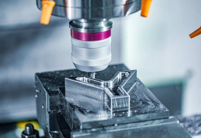
Obróbka CNC aluminium opiera się na kilku podstawowych procesach, z których każdy jest dostosowany do konkretnych geometrii i wymagań produkcyjnych. Zrozumienie tych operacji pozwala dobrać odpowiednią technikę do potrzeb danego projektu.
- Frezowanie CNC: Ten proces wykorzystuje obrotowe narzędzia tnące do usuwania materiału z nieruchomego przedmiotu roboczego wykonanego z aluminium. Maszyny wieloosiowe (3-osiowe lub 5-osiowe) umożliwiają wykonywanie skomplikowanych ścieżek narzędzia w celu obróbki złożonych kształtów, takich jak rowki, kieszenie i powierzchnie o złożonym profilu. Miękkość aluminium pozwala na frezowanie wysokoprędkościowe z dokładnością ±0,01 mm, co czyni ten materiał idealnym do produkcji wsporników lotniczych i obudów elektronicznych.
- Tornictwo CNC: W tym procesie przedmiot roboczy z aluminium obraca się, podczas gdy nieruchome narzędzie tnące nadaje mu kształt. Technika ta szczególnie dobrze sprawdza się przy produkcji elementów cylindrycznych, takich jak wały, tuleje i kołnierze. Dobrze opracowalne właściwości aluminium pozwalają na stosowanie wyższych prędkości obrotowych wrzeciona niż w przypadku stali, jednak należy zwrócić uwagę na odprowadzanie wiórków, ponieważ materiał ten ma tendencję do tworzenia długich, ciągliwych wiórków.
- Wiercenie CNC: Tworzenie precyzyjnych otworów pod elementy mocujące, zespoły lub przewody cieczy często następuje po operacjach frezowania lub tokarek. Miękkość aluminium czyni wiercenie bardzo wydajnym, jednak specjalistyczne wiertła pomagają zapobiegać powstawaniu lepkich wiórków, które mogą zatykać narzędzia w trakcie procesu.
- Cięcie strumieniem wody: Dla grubyh płyt aluminiowych lub zastosowań wrażliwych na ciepło cięcie strumieniem wody przetina materiał bez generowania naprężeń termicznych. Pozwala to zachować integralność strukturalną stopów takich jak 5052 lub 5083, co czyni tę metodę szczególnie wartościową przy produkcji elementów stosowanych w przemyśle morskim oraz dużych części o formacie pełnoformatowym.
Każda z tych technik CNC do obróbki aluminium wykorzystuje korzystne właściwości tego metalu, jednocześnie radząc sobie z jego specyficznymi wyzwaniami. Wynik? Lekkie, precyzyjne i trwałe komponenty dostarczane z wydajnością, jakiej po prostu nie potrafią osiągnąć cięższe metale.
Nie ma znaczenia, czy opracowujesz prototyp pojedynczego elementu, czy planujesz produkcję masową – zrozumienie tych podstawowych kwestii pozwoli Ci podejmować świadome decyzje dotyczące wymagań stawianych maszynom CNC do obróbki aluminium oraz ogólnej strategii produkcyjnej.
Przewodnik po doborze stopów aluminium do projektów precyzyjnej obróbki skrawaniem
Wybór odpowiedniego stopu aluminium może zadecydować o sukcesie lub porażce Twojego projektu obróbkowego. Możesz posiadać najbardziej zaawansowane wyposażenie CNC dostępne, ale wybór niewłaściwej gatunkowości prowadzi do pogorszenia wydajności, niepotrzebnych kosztów lub całkowitego uszkodzenia elementu. Jak więc poruszać się wśród „zupy literowej” oznaczeń stopów?
Decyzja sprowadza się do zrozumienia kompromisów. Każdy stop aluminium różnie balansuje wytrzymałość, obrabialność, odporność na korozję oraz koszt. Gdy zamawiasz blok aluminium do obróbki CNC, wybrana gatunkowość określa wszystko – od parametrów cięcia po trwałość gotowego elementu.
Porównanie stopów aluminium: 6061 vs 7075 vs 2024
Cztery stopy dominują w produkcji elementów aluminiowych: 6061, 7075, 2024 oraz 5052. Każdy z nich znajduje zastosowanie w określonych obszarach, w zależności od swoich unikalnych właściwości.
6061 Aluminium to praca konia roboczego przemysłu. Zawierający około 1% magnezu i 0,6% krzemu, ten stop oferuje doskonałą równowagę umiarkowanej wytrzymałości, doskonałej odporności na korozję oraz wyróżniającej się obrabialności. Jest znacznie łatwiejszy w obróbce niż alternatywy o wyższej wytrzymałości, generując krótsze wióry, które łatwiej jest kontrolować. Gdy potrzebujesz obrabianych elementów z aluminium, które nie wymagają ekstremalnej wytrzymałości, stop 6061 zapewnia opłacalne rezultaty.
7075 Aluminium jest stosowany w wymagających zastosowaniach, gdzie kluczowe znaczenie ma wytrzymałość. Dzięki zawartości cynku jako głównego pierwiastka stopowego w zakresie 5,6–6,1% oraz obecności magnezu i miedzi stop 7075 osiąga wytrzymałość na rozciąganie do 570 MPa — czyli niemal o 84% wyższą niż stop 6061. Jednak ta wyższa wytrzymałość wiąże się z pewnymi kompromisami: obniżoną odpornością na korozję spowodowaną wyższą zawartością miedzi, większym zużyciem narzędzi podczas obróbki oraz wyższą ceną, która zwykle przekracza cenę stopu 6061 o 25–35%.
aluminium 2024 jest ulubionym stopem przemysłu lotniczo-kosmicznego w zastosowaniach krytycznych pod względem zmęczenia materiału. Jego wysoka wytrzymałość przy niskiej masie czyni go idealnym do kadłubów samolotów, skrzydeł oraz konstrukcji nośnych. Podobnie jak stop 7075, jego podwyższona zawartość miedzi powoduje niższą odporność na korozję, co wymaga stosowania ochronnych powłok w trudnych warunkach środowiskowych. Obróbka stopu 2024 wiąże się z wyzwaniami, takimi jak utwardzanie w wyniku obróbki, co wymaga użycia ostrych narzędzi oraz ostrożnego doboru prędkości skrawania.
5052 aluminium stawia na pierwszym miejscu odporność na korozję zamiast maksymalnej wytrzymałości. Ten stop doskonale sprawdza się w środowiskach morskich, w przemyśle chemicznym oraz w zastosowaniach związanych z zbiornikami paliwa, gdzie występuje stała ekspozycja na wilgoć, sól lub substancje chemiczne o działaniu korozyjnym. Choć nie jest tak wytrzymał jak stopy 6061 lub 7075, jego łatwość kształtowania oraz trwałość w trudnych warunkach środowiskowych czynią go niezastąpionym w określonych zastosowaniach.
| Nieruchomości | 6061-T6 | 7075-T6 | 2024-T3 | 5052-H32 |
|---|---|---|---|---|
| Wytrzymałość na rozciąganie (MPa) | 310 | 570 | 485 | 230 |
| Wytrzymałość na rozciąganie (MPa) | 270 | 490 | 345 | 195 |
| Twardość (Brinell) | 95 | 150 | 120 | 60 |
| Ocena łatwości obróbki | Doskonały | Dobre | Umiarkowany | Dobre |
| Odporność na korozję | Doskonały | Umiarkowany | Sprawiedliwe | Doskonały |
| Typowe zastosowania | Elementy konstrukcyjne, sprzęt morski, ramy rowerów | Konstrukcje lotnicze, sprzęt wojskowy, narzędzia przeznaczone do obciążeń wysokich | Kadłuby samolotów, skrzydła, pojazdy wojskowe | Zbiorniki paliwa, elementy morskie, zbiorniki ciśnieniowe |
| Koszt względny | $ | $$$ | $$ | $ |
Zrozumienie oznaczeń stanu wyjściowego dla części frezowanych
Czy kiedykolwiek zastanawiałeś się, co tak naprawdę oznaczają litery i cyfry po oznaczeniu stopu? Kod stanu wyjściowego precyzyjnie określa sposób obróbki aluminium – a to bezpośrednio wpływa na końcową wydajność Twoich frezowanych części aluminiowych.
Oznaczenia stanu wyjściowego aluminium podlegają ustandaryzowanemu systemowi, który przekazuje informacje o obróbce cieplnej oraz warunkach walcowania zimnego:
- F (po wykonaniu): Brak specjalnej obróbki cieplnej ani walcowania zimnego po kształtowaniu. Właściwości zależą od procesu kształtowania.
- O (Zgniecione): Najmiękki i najbardziej plastyczny stan. Maksymalna kuteść, ale najniższa wytrzymałość.
- H (walcowane zimno): Stosowane do wyrobów walcowanych, wzmocnionych przez walcowanie zimne. Pierwsza cyfra po literze H wskazuje konkretny proces wzmocnienia, a druga cyfra – stopień wzmocnienia.
- T (po hartowaniu roztworu): Wyroby wzmocnione za pomocą kontrolowanych cykli nagrzewania i chłodzenia, czasem w połączeniu z wystarzaniem lub walcowaniem zimnym.
Najczęstsze oznaczenia stanu wyjściowego T, z którymi się spotkasz, to:
- T3: Rozwiązanie poddane obróbce cieplnej, zimne kucie, a następnie naturalne starzenie. Często stosowane w stopach aluminium 2024 w zastosowaniach lotniczych.
- T6: Rozwiązanie poddane obróbce cieplnej, a następnie sztuczne starzenie. Jest to najbardziej powszechnie określany stan wyjściowy dla stopów 6061 i 7075, zapewniający optymalną wytrzymałość.
- T7: Rozwiązanie poddane obróbce cieplnej, a następnie nadstarzenie/stabilizacja w celu poprawy odporności na korozję napięciową, choć przy nieco niższej wytrzymałości.
Dla stopów utwardzanych odkształceniem, takich jak 5052, dominują oznaczenia H:
- H32: Utwardzanie odkształceniem i stabilizacja do stanu „ćwierć-twardego”. Zapewnia równowagę między wytrzymałością a kuteścią.
- H34: Utwardzanie odkształceniem i stabilizacja do stanu „pół-twardego”. Wyższa wytrzymałość niż w przypadku H32, ale mniejsza kuteść.
Wybór odpowiedniego stanu wyjściowego jest równie ważny co wybór samego stopu. Element wykonany ze stopu 6061-T6 zachowa się zupełnie inaczej niż element ze stopu 6061-O podczas obróbki skrawaniem oraz w trakcie eksploatacji. Przy określaniu aluminiowych części obrobionych skrawaniem należy zawsze podawać pełne oznaczenie — zarówno stop, jak i stan wyjściowy razem określają, co otrzymasz.
Zrozumienie tych różnic pozwala zoptymalizować zarówno wykonalność produkcyjną, jak i wydajność w użytkowaniu końcowym, zapewniając podstawę do podejmowania świadomych decyzji dotyczących parametrów cięcia oraz strategii doboru narzędzi.
Parametry techniczne i narzędzia do operacji CNC na aluminium
Wybrałeś odpowiedni stop i hart dla swojego projektu. Teraz pojawia się pytanie, które oddziela wyniki zadowalające od wyjątkowych: jak w rzeczywistości przetwarzać ten materiał? Frezowanie aluminium może wydawać się proste — przecież jest miększe niż stal — ale to założenie wprowadza wiele warsztatów w błędne ścieżki.
Oto rzeczywistość. Miękkość aluminium stwarza unikalne wyzwania które wymagają specyficznych podejść. Materiał ten topi się w znacznie niższej temperaturze niż stal, co oznacza, że wióry mogą przegrzewać się i zlepić się bezpośrednio z narzędziem skrawającym. Gdy to się dzieje, krawędź tnąca szybko tępi się, obciążenia mechaniczne rosną, a narzędzie ulega przedwczesnemu zużyciu.
Optymalne parametry skrawania stopów aluminium
Podczas frezowania CNC aluminium prędkość jest Twoim sojusznikiem – ale tylko wtedy, gdy jest połączona z odpowiednimi posuwami. Zgodnie z informacjami firmy CNC Solutions, przy stosowaniu narzędzi węglikowych aluminium wymaga prędkości skrawania w zakresie 300–600 metrów na minutę, co jest porównywalne do frezowania drewna. Jednak w przeciwieństwie do drewna optymalne posuwy i prędkości dla aluminium mieszczą się w znacznie węższym zakresie.
Wysokie prędkości obrotowe wrzeciona charakteryzują skuteczne frezowanie aluminium. Jednak tutaj wielu frezarzy popełnia błąd: łączy wysokie obroty z zbyt niskimi prędkościami posuwu. W takim przypadku narzędzie spędza więcej czasu na tarcie o aluminium niż na jego rzeczywiste skrawanie. Jaki jest efekt? Zwiększenie temperatury pracy i znaczne skrócenie trwałości narzędzia.
Zasady określające dobór parametrów obejmują:
- Prędkość skrawania (SFM): Dla stopów aluminium odlewniczych, takich jak 308, 356 i 380, Harvey Performance zaleca 500–1000 SFM. Stopy walcowane, takie jak 2024, 6061 i 7075, mogą być obrabiane z wyższą prędkością – 800–1500 SFM.
- Obliczanie prędkości obrotowej wrzeciona: Użyj wzoru (3,82 × SFM) ÷ średnica narzędzia, aby określić punkt wyjścia. Frezarka CNC do obróbki aluminium wyposażona w frez końcowy o średnicy 0,5 cala pracująca przy prędkości skrawania 1000 SFM rozpocznie pracę przy około 7640 obr/min.
- Równowaga prędkości posuwu: Dobierz prędkość posuwu odpowiednio do prędkości obrotowej wrzeciona, aby zapewnić właściwą grubość wióra. Zbyt niska prędkość powoduje tarcie i nagrzewanie się, natomiast zbyt wysoka grozi uszkodzeniem narzędzia.
- Głębokość skrawania: Mniejsze głębokości ułatwiają usuwanie wiórków, szczególnie w głębokich kieszeniach. Testy przeprowadzone przez OSG na maszynach serii Makino MAG dały imponujące wyniki przy głębokości osiowej 15 mm i głębokości promieniowej 20 mm przy prędkości obrotowej 30 000 obr/min.
| Parametry | Aluminium odlewnicze (308, 356, 380) | Aluminium walcowane (2024, 6061, 7075) |
|---|---|---|
| Prędkość skrawania (SFM) | 500-1000 | 800-1500 |
| Wiązka wiórków (na ząbek) | Umiarkowana — do dobrania w zależności od liczby rowków | Wyższe obciążenia są możliwe przy odpowiednim usuwaniu wiórków |
| Głębokość skrawania promieniowego | Do 50 % średnicy narzędzia przy toczeniu wykończeniowym | Do 90 % średnicy narzędzia przy sztywnych ustawieniach |
| Głębokość skrawania wzdłuż osi | Płytkie dla kieszeni; głębsze dla strategii HEM | Pełna długość żebra możliwa przy odpowiednim narzędziu |
| Dopływ chłodziwa | Zatapianie lub mgiełka do usuwania wiórków | Mgiełka przez narzędzie jest preferowana przy obróbce wysokoprędkościowej |
Wybór narzędzi do uzyskania doskonałej jakości powierzchni
Dlaczego aluminium wymaga innego narzędzi niż stal? Odpowiedź tkwi w usuwaniu wiórków i przyczepianiu się materiału. Maszyna CNC do frezowania aluminium wyposażona w narzędzia zaprojektowane do obróbki stali szybko napotka problemy — zatkane żebra, tworzenie się warstwy przyrostowej (built-up edge) oraz pogorszenie jakości powierzchni.
Najważniejszym czynnikiem przy wyborze narzędzi tnących do aluminium jest maksymalizacja przestrzeni na odprowadzanie wiórków. Im więcej żeberek ma frez, tym mniej miejsca pozostaje na ucieczkę wiórków. Dlatego tradycyjnie dwużebrowe frezy czołowe są preferowanym wyborem przy frezowaniu CNC aluminium, choć trzyżebrowe konstrukcje dobrze sprawdzają się przy operacjach wykańczających przy odpowiednich parametrach.
Rozważmy następujący scenariusz: próbujesz wykonać cięcie o pełnym średnicy w aluminium za pomocą frezu czołowego z czterema rowkami. Rowki zapychają się niemal natychmiast, nagromadza się ciepło i narzędzie ulega uszkodzeniu. W przypadku frezów z dwoma lub trzema rowkami wióry są skutecznie usuwane, a żywotność narzędzia znacznie się wydłuża.
- Frezy czołowe z dwoma rowkami: Standardowy wybór do operacji roughing (obróbki zgrubnej) i frezowania rowków. Maksymalna przestrzeń na wióry kompensuje wysokie tempo usuwania materiału, jakie umożliwia obróbka aluminium. Używaj najkrótszej możliwej długości narzędzia, aby zminimalizować ugięcie.
- Frezy czołowe z trzema rowkami: Doskonałe do operacji wykańczających oraz ścieżek narzędzia stosowanych w wysokowydajnym frezowaniu (HEM). Zapewniają dobry kompromis między przestrzenią na wióry a jakością chropowatości powierzchni.
- Niepowlekany węglik spiekany: Badania przeprowadzone przez OSG Tap and Die wykazały, że niepowlekany węglik spiekany o gruboziarnistej strukturze osiąga lepsze wyniki niż powłoki TiN, TiCN, TiAlN lub AlTiN podczas obróbki aluminium w wysokich prędkościach. Proces napylania metodą PVD powoduje chropowatość powierzchni i reaktywność chemiczną, które sprzyjają przywieraniu aluminium.
- Powłoka ZrN (azotek cyrkonu): Specjalistyczne powłoki zaprojektowane specjalnie dla materiałów nieżelaznych. Zmniejszają tarcie i przyczepność materiału bez wad powłok opartych na tytanie.
- Powłoka DLC (Diamond-Like Carbon): Tworzy wyjątkowo gładką, chemicznie obojętną powierzchnię, która znacznie wydłuża żywotność narzędzi. Zwiększa koszt narzędzia o około 20–25%, ale zapewnia istotne korzyści w zakresie wydajności.
- Wybór kąta śrubowienia: Kąt śrubowienia 35° lub 40° sprawdza się dobrze przy tradycyjnym toczeniu i frezowaniu rowków. Dla operacji wykańczania oraz strategii HEM kąty śrubowienia 45° zapewniają bardziej intensywne usuwanie wiórków. Jednak przy bardzo wysokich prędkościach niższe kąty śrubowienia (20–25°) zmniejszają tarcie i zapobiegają przyczepianiu się wiórków do narzędzia.
- Węglik ziarno-gruby vs. węglik ziarno-cienki: Chociaż węglik ziarno-cienki zachowuje ostrzejsze krawędzie tnące, jego wysoka zawartość kobaltu reaguje z aluminium w podwyższonych temperaturach. Węglik ziarno-gruby zapewnia wystarczającą twardość przy jednoczesnym minimalizowaniu przyczepności – stanowi lepszy kompromis dla obróbki CNC aluminium.
Jedna ostatnia kwestia: usuwanie wiórków nie odbywa się automatycznie. Strumienie sprężonego powietrza, chłodzenie przez narzędzie lub systemy mgiełkowe aktywnie usuwają wiórki ze strefy cięcia. Bez prawidłowego zarządzania wiórkami nawet najlepsze narzędzia ulegną przedwczesnemu zużyciu. Doświadczone zakłady traktują usuwanie wiórków z taką samą powagą jak dobór narzędzi — ponieważ w obróbce aluminium te dwa aspekty są nierozłączne.
Gdy parametry i narzędzia zostały dobrze dobrane, kolejnym wyzwaniem staje się projektowanie części, które rzeczywiście wykorzystują te możliwości, unikając przy tym kosztownych pułapek produkcyjnych.
Wytyczne projektowania z myślą o łatwości produkcji w obróbce aluminium
Wybrałeś idealny stop, dostosowałeś parametry cięcia i zdecydowałeś się na specjalistyczne narzędzia. Ale oto niezbyt przyjemna prawda: żadna z tych czynności nie ma znaczenia, jeśli projekt Twojego elementu przeciwdziała samemu procesowi obróbki skrawaniem. Projektowanie z myślą o możliwościach produkcyjnych – czyli DFM – decyduje o tym, czy Twoje niestandardowe elementy z aluminium zostaną wyprodukowane szybko i tanio, czy też staną się kosztownym problemem, który przekroczy budżet i terminy realizacji.
Dlaczego DFM jest tak kluczowe w przypadku części z aluminium wykonanych metodą CNC? Każda cecha, którą określisz – grubość ścianek, promienie zaokrągleń narożników, głębokość otworów, długość gwintów – wpływa bezpośrednio na czas cyklu obróbkowego, zużycie narzędzi oraz wskaźnik odpadów. Dobra wiadomość? Stosowanie sprawdzonych wytycznych nie ogranicza swobody projektowania. Wręcz przeciwnie – koncentruje ją tam, gdzie rzeczywiście ma znaczenie, eliminując jednocześnie cechy dodające koszt bez jakiejś funkcjonalnej korzyści.
Wytyczne dotyczące grubości ścianek i cech konstrukcyjnych dla elementów z aluminium
Cienkie ścianki wyglądają elegancko na ekranach CAD, ale stają się koszmarem na halach produkcyjnych. Gdy narzędzia skrawające działają na niepodpartym materiale, cienkie elementy drgają, uginają się i ulegają odkształceniom. Skutkiem tego jest niska jakość powierzchni, niedokładność wymiarowa oraz potencjalne odrzucenie detali.
Zgodnie z praktyką branżową udokumentowaną przez Wevolver , części aluminiowe powinny mieć minimalną grubość ścianek wynoszącą około 1,0 mm; grubość 0,6–0,7 mm jest dopuszczalna jedynie w przypadku krótkich odcinków i przy ściśle kontrolowanych warunkach. Jednak dla części o długości przekraczającej 100 mm doświadczone warsztaty CNC zalecają zwiększenie tej minimalnej grubości do 3 mm, aby zapobiec odkształceniom podczas obróbki.
Ponadto każdy element w Twoich niestandardowych detalach CNC ma praktyczne ograniczenia wynikające z geometrii narzędzi i dynamiki maszyny:
- Głębokość wnęki/pojemnika: Dla uzyskania optymalnych rezultatów głębokość powinna wynosić około trzykrotność szerokości wnęki. Choć możliwe jest osiągnięcie głębokości nawet 8–10-krotności średnicy frezu, to głębsze wnęki wymagają dłuższych narzędzi, które bardziej uginają się pod wpływem obciążenia, powodując zwiększenie promieni zaokrągleń wewnętrznych oraz pogorszenie jakości powierzchni.
- Promienie zaokrągleń wewnętrznych: Określ promień zaokrąglenia krawędzi (fillet) na poziomie co najmniej 25–35 % głębokości wnęki. Ponieważ frezy czołowe mają kształt cylindryczny, idealnie ostre narożniki wewnętrzne są fizycznie niemożliwe — promień narożnika będzie zawsze wynosił co najmniej tyle, ile promień narzędzia.
- Promień krawędzi dna: Docelowe ostre krawędzie lub promienie poniżej 0,5 mm. Małe promienie w tym miejscu zapobiegają widocznym śladom narzędzi, zachowując przy tym dokładność geometryczną.
- Wysokie elementy (słupki/żebra): Zachowaj stosunek wysokości do szerokości nie większy niż 3,5:1. Elementy o większej wysokości, aż do 5:1, są możliwe przy starannej obróbce i odpowiednim zamocowaniu, jednak smukła geometria ulega drganiom, odkształceniom i utracie tolerancji.
- Głębokość otworu: Standardowe wiertła pozwalają na wykonywanie czystych otworów o głębokości do 3,5 średnicy. Głębokości przekraczające 8–9 średnic wymagają cykli wiercenia z wycofywaniem (peck-drilling), co znacznie wydłuża czas obróbki.
- Małe cechy: Zachowaj minimalny rozmiar cechy na poziomie 3 mm lub większym. Cechy o rozmiarach 0,3–0,5 mm wymagają narzędzi mikro, precyzyjnych wrzecion oraz mniejszych posuwów — co dramatycznie zwiększa koszty.
Stosuj ścisłe допусki tylko tam, gdzie jest to konieczne. Nadmierna precyzja zwiększa koszty, zużycie narzędzi oraz czas kontroli jakości, nie poprawiając przy tym funkcjonalności elementu.
Unikanie typowych błędów projektowych powodujących wzrost kosztów
Wyobraź sobie, że wysyłasz starannie zaprojektowany element na wyceny — i nagle okazuje się, że kilka drobnych cech podwoiła cenę. Takie sytuacje występują stale, gdy inżynierowie nie biorą pod uwagę, jak decyzje projektowe przekładają się na operacje maszynowe.
Specyfikacje gwintów są dobrym przykładem tego problemu. Zgodnie z wytycznymi branżowymi, w aluminium należy stosować gwinty M5 lub większe. Choć gwinty M3 są możliwe do wykonania przy użyciu precyzyjnego narzędzia, mniejsze gwinty w miękkim aluminium łatwo się obijają i wymagają delikatnych operacji gwintowania. Ponadto, długość zakręcenia przekraczająca 2–2,5 średnicy nominalnej rzadko zwiększa wytrzymałość mechaniczną — jedynie wydłuża czas obróbki.
Poniżej przedstawiono najczęściej popełniane błędy projektowe, które powodują wzrost kosztów niestandardowych projektów obróbki aluminium:
- Niestandardowe średnice otworów: Określenie nietypowych średnic zmusza warsztat do frezowania otworów jako małych wnęk zamiast wiercenia ich. Standardowe średnice wiertła umożliwiają szybsze i tańsze obróbkę — należy z nich korzystać, chyba że aplikacja wymaga inaczej.
- Niepotrzebnie ścisłe допусki: Standardowa obróbka zapewnia dokładność ±0,10 mm (±0,004 cala) bez dodatkowych środków. Ustalenie ścisłych tolerancji na poziomie ±0,02–0,03 mm jest możliwe, ale wiąże się to z wydłużeniem czasu kontroli, wolniejszymi posuwami oraz potencjalnym koniecznością poprawek. Ścisłe tolerancje należy zarezerwować dla powierzchni stykających się i funkcjonalnych pasowań.
- Wcięcia bez luzu: Wcięcia wymagają specjalistycznych frezów, takich jak frezy T-slot lub frezy typu lollipop. Szerokość wcięcia należy określić w zakresie 4–35 mm, a luz boczny powinien wynosić co najmniej trzykrotność głębokości wcięcia. Brak odpowiedniego luzu powoduje drgania narzędzia i jego uszkodzenie.
- Ignorowanie naprężeń materiału: Usunięcie dużej ilości materiału z jednej strony elementu uwalnia wewnętrzne naprężenia, co prowadzi do odkształceń. Należy projektować symetryczne wycięcia tam, gdzie to możliwe, dodawać żeberka konstrukcyjne co 50 mm w długich i cienkich przekrojach oraz rozważyć zastosowanie materiału poddanego odpuszczaniu naprężeń (6061-T651) w przypadku geometrii szczególnie niewrażliwych na odkształcenia.
- Ignorowanie złożoności ustawienia: Za każdym razem, gdy część musi zostać ponownie umieszczona w maszynie, ponoszą Państwo koszty ponownego mocowania, weryfikacji pozycji oraz dodatkowej kontroli jakości. Projektujcie obróbkę w jednym ustawieniu zawsze, gdy jest to możliwe — nawet jeśli oznacza to dodanie elementów łączących lub podział zespołów.
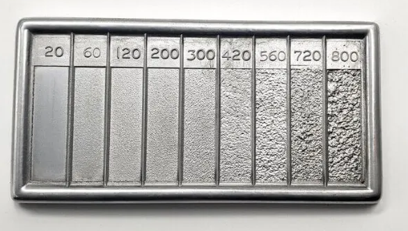
Wymagania dotyczące chropowatości powierzchni również często zaskakują inżynierów. Aluminium po obróbce skrawaniem osiąga zwykle chropowatość Ra 3,0 µm z widocznymi śladami narzędzia. Piaskowanie, polerowanie lub anodowanie zmniejszają chropowatość do wartości Ra 0,4–0,8 µm — jednak każda z tych operacji zwiększa koszty i czas realizacji. Określajcie wymagania dotyczące wykończenia powierzchni na podstawie funkcji, a nie wyłącznie estetyki.
Inwestycja w projektowanie przygotowane do produkcji (DFM) w fazie projektowania przynosi korzyści na całym etapie produkcji. Indywidualne wyroby z aluminium zgodne z tymi wytycznymi są szybciej obrabiane, generują mniej braków i mają niższy koszt jednostkowy. Co ważniejsze, działają one zgodnie z założeniami, ponieważ proces produkcyjny wspiera, a nie kompromituje intencje inżynierskie.
Gdy masz już gotowe do produkcji projekty, kolejne kluczowe pytanie brzmi: jakiego poziomu dokładności można w rzeczywistości osiągnąć i kiedy określenie ścislszych tolerancji uzasadnia dodatkowe koszty?
Wyjaśnienie specyfikacji dopuszczalnych odchyłek wymiarowych oraz możliwości osiągania precyzji
Zaprojektowałeś element, który idealnie spełnia wszystkie wytyczne DFM. Ale istnieje pytanie decydujące o tym, czy Twoje części z aluminium wykonane na frezarce CNC rzeczywiście pasują do siebie: jakiej dokładności można realistycznie osiągnąć? Zrozumienie możliwości tolerancyjnych to nie tylko wiedza techniczna – to różnica między funkcjonalnymi złożeniami a drogim odpadem.
Odpowiedź zależy od kilku powiązanych ze sobą czynników: wybranego stopu, operacji obróbkowej, kalibracji sprzętu oraz kontroli warunków środowiskowych. Przeanalizujmy, jakie dokładności są rzeczywiście osiągalne i kiedy opłaca się płacić za ścislsze tolerancje.
Standardowe i precyzyjne możliwości tolerancji
Współczesne centra CNC zapewniają imponującą dokładność pozycjonowania — w granicach ±0,005 mm zgodnie z danymi firmy Aluphant jednak prawdziwa precyzja zależy od czynników innych niż tylko specyfikacje maszyny. Harmonogramy kalibracji, sztywność wrzeciona, kompensacja termiczna, a nawet temperatura w pomieszczeniu wpływają na końcową dokładność wymiarową.
Różne operacje obróbkowe osiągają różne poziomy precyzji. Szlifowanie zapewnia najściślejsze допусki w zakresie IT5–IT8, podczas gdy wiercenie daje najluźniejsze, wynoszące około IT10. W przypadku większości zastosowań CNC aluminium operacje frezowania i toczenia znajdują się gdzieś pomiędzy tymi wartościami.
| Operacja obróbkowa | Typowy stopień dokładności | Osiągalna precyzja | Chropowatość powierzchni (Ra) |
|---|---|---|---|
| Frezowanie ścisłe | IT9–IT10 | ±0,10 mm (±0,004 cala) | 6,3–3,2 µm |
| Frezowanie wykańczające | IT7–IT8 | ±0,05 mm (±0,002 cala) | 1,6–0,8 µm |
| Frezowanie precyzyjne | IT6-IT7 | ±0,013 mm (±0,0005 cala) | 0,8–0,4 µm |
| Wstępną obróbkę | IT9–IT10 | ±0,10 mm | 6,3–3,2 µm |
| Ostateczne obrabianie obrotowe | IT7–IT8 | ±0,05 mm | 1,6–0,8 µm |
| Standardowe wiercenie | IT10 | ±0,13 mm | 12,5–6,3 µm |
| Otwory rozszerzane | IT7–IT8 | ±0,025 mm | 1,6–0,8 µm |
| Szlifowanie | IT5–IT6 | ±0.005 mm | 0,4–0,16 µm |
Wybór stopu ma bezpośredni wpływ na osiąganą precyzję. Według badań branżowych, aluminium 6061 oferuje doskonałą stabilność wymiarową i obrabialność, co czyni je idealnym do obróbki z wąskimi tolerancjami. Miękkie stopy, takie jak 6063, odkształcają się łatwiej pod wpływem sił skrawania. Mocniejsze gatunki, takie jak 7075, zapewniają wyższą wytrzymałość, ale charakteryzują się większą rozszerzalnością cieplną i odkształceniami naprężeniowymi podczas obróbki części aluminiowych.
Oto kluczowy czynnik, który często przeocza wielu inżynierów: aluminium rozszerza się o około 23 µm na metr przy wzroście temperatury o 1 °C. Część o długości jednego metra, wyprodukowana w ciepłej warsztatowej hali produkcyjnej, może mieć wymiar o 0,023 mm większy niż ta sama część pomierzona w klimatyzowanym laboratorium kontrolno-pomiarowym. Dlatego też zakłady zajmujące się precyzyjną obróbką aluminium utrzymują kontrolowane warunki środowiskowe — zwykle 20 °C ± 1 °C — zarówno podczas obróbki, jak i kontroli jakości.
Kiedy ścisłe tolerancje są opłacalne
Brzmi skomplikowanie? Nie musi tak być. Kluczem jest dopasowanie specyfikacji tolerancji do rzeczywistych wymagań funkcjonalnych, a nie automatyczne wybieranie najbardziej restrykcyjnych wartości, jakie może osiągnąć dostawca.
Standardowe tolerancje dwustronne ±0,005 cala (±0,127 mm) są wystarczające dla większości metalowych części wykonanych metodami skrawania bez konieczności stosowania obróbki specjalnej. Osiągnięcie odniesienia – precyzji ±0,0005 cala (±0,013 mm) – wymaga wolniejszych prędkości posuwu, wielokrotnych przejść wykańczających, kalibrowanego sprzętu, środowisk o kontrolowanej temperaturze oraz dodatkowego czasu na inspekcję. Każdy z tych czynników zwiększa koszty.
Kiedy inwestycja w ścislsze tolerancje ma sens?
- Powierzchnie stykowe: Interfejsy, w których części muszą dokładnie się pozycjonować – np. pasowania łożysk, powierzchnie wałów, punkty odniesienia montażowe – uzasadniają stosowanie ścislszych specyfikacji.
- Powierzchnie uszczelniające: Wżerki pod uszczelki typu O-ring, powierzchnie pod uszczelki płaskie oraz kanały przepływowe wymagają kontrolowanej geometrii w celu zapobiegania wyciekom.
- Komponenty wirujące z wysoką prędkością: Niewyrównoważenie spowodowane odchyleniami wymiarowymi prowadzi do drgań, hałasu oraz przedwczesnego zużycia.
- Wyrównywanie optyczne lub elektroniczne: Uchwyty czujników, obudowy soczewek oraz konstrukcje anten często wymagają precyzji na poziomie mikronów.
W przypadku cech niestotnych funkcjonalnie — otworów luzowych, zewnętrznych konturów, powierzchni dekoracyjnych — zastosowanie standardowych tolerancji pozwala obniżyć koszty bez wpływu na funkcjonalność. Dokładne tolerancje należy stosować selektywnie, a nie powszechnie.
Geometria i tolerancje geometryczne (GD&T) zapewniają dodatkową kontrolę wykraczającą poza proste ograniczenia wymiarowe. Jak wyjaśnia firma Protolabs, oznaczenia GD&T, takie jak rzeczywista pozycja, płaskość, cylindryczność, współśrodkowość i prostopadłość, definiują relacje między cechami — nie tylko ich indywidualne wymiary. Na przykład otwór może mieścić się w dopuszczalnym zakresie średnicy, ale być nieprawidłowo położony, co spowoduje awarię montażu. Oznaczenia rzeczywistej pozycji z kwalifikatorami maksymalnego warunku materiału (MMC) lub minimalnego warunku materiału (LMC) pozwalają wykryć takie problemy.
Oznaczenia płaskości stają się szczególnie istotne w przypadku cienkich elementów wykonanych z aluminium. Wewnętrzne naprężenia materiału oraz siły docisku podczas obróbki mogą powodować odkształcenia (wygięcia) po zwolnieniu detalu. Tolerancja płaskości zgodnie z systemem GD&T określa dwie równoległe płaszczyzny, pomiędzy którymi musi się znajdować obrabiana powierzchnia, zapewniając tym samym wymagane właściwości funkcjonalne niezależnie od pomiarów poszczególnych punktów.
Związek między tolerancją a kosztem jest przybliżony wykładniczo — dwukrotne zmniejszenie wartości tolerancji zwiększa koszty o więcej niż połowę. Zanim określisz dokładność przekraczającą standardowe możliwości technologiczne, zastanów się: czy funkcja tego elementu rzeczywiście tego wymaga? Jeśli nie, płacisz za możliwości, których nigdy nie wykorzystasz. Rozsądne określanie tolerancji polega na znalezieniu równowagi między wymaganiami inżynierskimi a ekonomiką produkcji — zapewnia to niezawodne części z aluminium wykonane metodą CNC bez niepotrzebnych wydatków.
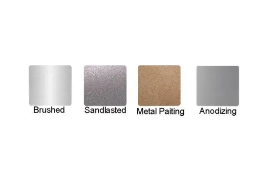
Opcje wykańczania powierzchni dla komponentów z aluminium wykonanych metodą frezowania
Twój wyprodukowany element z aluminium właśnie opuścił maszynę — czyste cięcia, ścisłe допусki, idealna geometria. Ale oto co wielu inżynierów pomija: surowa powierzchnia po obróbce to tylko punkt wyjścia. Obróbka powierzchni przekształca funkcjonalny metal w komponenty odporno na korozję, odporne na zużycie, przewodzące prąd elektryczny (lub nieprzewodzące) oraz wyglądające dokładnie tak, jak tego wymaga Twoje zastosowanie.
Wybór odpowiedniego wykończenia nie dotyczy wyłącznie estetyki. Każdy producent wyrobów z aluminium wie, że wybór wykończenia ma bezpośredni wpływ na wydajność części, harmonogram realizacji projektu oraz całkowity koszt. Niezależnie od tego, czy poszukujesz dostawcy niestandardowej obróbki aluminium w pobliżu, czy współpracujesz z dostawcą globalnym, zrozumienie dostępnych opcji pozwala Ci określić dokładnie to, czego wymaga Twoje zastosowanie — ani więcej, ani mniej.
Opcje anodowania i ich korzyści eksploatacyjne
Anodowanie wyróżnia się spośród innych powłok, ponieważ nie tylko pokrywa aluminium – przekształca je. Jest to proces elektrochemiczny, w którym pogrubiana jest naturalna warstwa tlenku obecna na powierzchni aluminium, tworząc ochronę, która jest dosłownie zintegrowana z materiałem podstawowym. W przeciwieństwie do farb lub powłok metalicznych, które mogą odspajać się lub łuszczyć, warstwy anodowe nie odkształcą się ponieważ są częścią samego metalu.
Dwa typy anodowania dominują w przetwórstwie aluminium: typ II i typ III. Każdy z nich spełnia określone zadania w zależności od wymaganych właściwości użytkowych.
Anodowanie typu II (anodowanie konwencjonalne lub siarkowe) wytwarza warstwy tlenku o grubości zwykle od 0,0001 do 0,001 cala. Proces ten zapewnia:
- Różnorodność kolorów: Barwniki wprowadzane w trakcie obróbki pozwalają uzyskać praktycznie dowolny kolor – idealnie nadaje się to do produktów konsumenckich, elementów architektonicznych oraz komponentów z naniesioną marką.
- Umiarkowana ochrona przed korozją: Zwiększoną odporność w porównaniu do czystego aluminium, odpowiednią do zastosowań wewnątrz pomieszczeń oraz umiarkowanego oddziaływania czynników zewnętrznych.
- Efektywność kosztowa: Niższe koszty przetwarzania w porównaniu z typem III czynią tę metodę opłacalną dla dekoracyjnych elementów produkowanych w dużych ilościach.
- Izolacja elektryczna: Warstwa anodowa staje się nieprzewodząca, co sprawdza się w obudowach elektronicznych wymagających izolacji.
Anodowanie typu III (anodowanie twardą warstwą) tworzy znacznie grubsze warstwy tlenku — zwykle przekraczające 0,002 cala. Ten specjalizowany proces zapewnia:
- Wyjątkowa twardość: Znaczny wzrost twardości powierzchni, dzięki czemu jest on idealny w zastosowaniach narażonych na intensywne zużycie.
- Wyższa odporność na korozję: Grube bariery tlenkowe chronią komponenty w surowych środowiskach, takich jak środowisko morskie, przemysł chemiczny oraz zewnętrzne zastosowania przemysłowe.
- Ochrona przed ścieraniem: Części ruchome, powierzchnie ślizgowe oraz interfejsy o wysokim współczynniku tarcia korzystają z wytrzymałej warstwy anodowej twardzej.
- Ograniczone opcje kolorystyczne: Zazwyczaj przezroczysta lub czarna, choć dostępne są również niektóre opcje barwników.
Jedno kluczowe zagadnienie: anodowanie zwiększa wymiary warstwy. Typ II zwykle zwiększa grubość o 0,0002–0,001 cala na powierzchnię, podczas gdy Typ III może zwiększyć ją o 0,001–0,003 cala. W przypadku elementów o ścisłych tolerancjach, takich jak połączenia wciskane lub gwintowane otwory, stosuje się maskowanie, aby zapobiec wpływowi powłoki na krytyczne wymiary.
Dobieranie wykończeń powierzchni do wymagań zastosowania
Ponad anodowaniem istnieje kilka opcji wykończenia spełniających konkretne wymagania użytkowe. Odpowiedni wybór zależy od funkcji, jaką musi pełnić dany element.
| Typ wykończenia | Odporność na korozję | Odporność na zużycie | Przewodnictwo elektryczne | Typowe zastosowania | Koszt względny |
|---|---|---|---|---|---|
| Anodowanie typu II | Dobre | Umiarkowany | Niesprawny elektrycznie | Urządzenia elektroniczne dla konsumentów, listewki architektoniczne, elementy dekoracyjne | $$ |
| Anodowanie typu III | Doskonały | Doskonały | Niesprawny elektrycznie | Elementy lotnicze, sprzęt wojskowy, maszyny przeznaczone do intensywnego użytku | $$$ |
| Malowanie proszkowe | Dobre | Dobre | Niesprawny elektrycznie | Meble ogrodowe, listewki samochodowe, obudowy sprzętu AGD | $$ |
| Konwersja chromianowa (Alodine) | Umiarkowany | Niski | Wykonujące | Uziemienie elektryczne, grunt pod malowanie, ekranowanie przed interferencjami elektromagnetycznymi (EMI) | $ |
| Wyrzucanie z wiązki | Brak (wymaga powłoki) | Brak | Wykonujące | Przygotowanie estetyczne, poprawa przyczepności farby, jednolity matowy wygląd | $ |
| Wykończenie szczotkowane | Brak (wymaga powłoki) | Brak | Wykonujące | Panele dekoracyjne, czoła urządzeń AGD, tablice informacyjne | $ |
Malowanie proszkowe nakłada suchy proszek polimerowy metodą elektrostatyczną, a następnie utwardza go w temperaturze, tworząc grube, trwałe powłoki. Zgodnie z przewodnikiem postrzegania powierzchni firmy Fictiv, malowanie proszkowe dostępne jest w praktycznie nieograniczonej liczbie kolorów i stopni połysku, wykazuje odporność na zadrapania i odpryskiwanie oraz zapewnia skuteczną ochronę przed warunkami atmosferycznymi. Proces utwardzania wymaga jednak temperatury 163–232 °C – co czyni go nieodpowiednim dla zespołów wrażliwych na ciepło. Elementy o ścisłych tolerancjach wymagają zamaskowania, ponieważ powłoka dodaje mierzalną grubość.
Powieka przekształcająca chromaty (Alodine lub powłoka chemiczna) tworzy cienką warstwę ochronną zachowującą przewodność elektryczną i termiczną aluminium – cechę, jakiej żadna inna powłoka nie zapewnia. Dlatego też jest ona niezbędna w zastosowaniach związanych z uziemieniem, ekranowaniem przed zakłóceniami elektromagnetycznymi (EMI) oraz elementami wymagającymi odprowadzania ciepła. Powłoka stanowi również doskonałą bazę do kolejnego malowania. Kolor powłoki może być przezroczysty, złoty lub beżowy – w zależności od konkretnej formuły.
Wyrzucanie z wiązki wykorzystuje naciskowe strumienie kulek szklanych lub ceramicznych w celu stworzenia jednolitych matowych powierzchni. Choć samo w sobie nie zapewnia ochrony przed korozją, piaskowanie kulkami ukrywa ślady obróbki skrawaniem, poprawia przyczepność farby oraz nadaje gładki, satynowy wygląd charakterystyczny dla produktów konsumenckich wysokiej klasy. Po połączeniu z anodowaniem tworzy charakterystyczną powłokę obserwowaną na elektronice premium.
Nabielone skończenia tworzą kierunkowe wzory ziarnistości za pomocą procesów ściernych. Są czysto estetyczne; szlifowanie sprawdza się dobrze w przypadku widocznych paneli i elementów dekoracyjnych, ale wymaga stosowania ochronnej warstwy przeźroczystej w środowiskach narażonych na korozję.
Zanim określi się jakikolwiek wykończenie dla projektu z blachy aluminiowej, należy rozważyć następujące kluczowe pytania:
- W jakim środowisku będzie działał dany element? Woda morska, chemikalia, ekspozycja na promieniowanie UV oraz wilgotność wpływają na wymagania dotyczące wykończenia.
- Czy część wymaga przewodności elektrycznej lub cieplnej? Większość wykończeń działa izolująco — tylko konwersja chromianowa zachowuje przewodność.
- Jakim warunkom zużycia będą podlegać powierzchnie? Ślizgające się styki, wielokrotne obsługiwania oraz narażenie na działanie środków ściernych wymagają powłoki twardzej lub malowania proszkowego.
- Czy istnieją elementy o ścisłych tolerancjach, które wymagają zabezpieczenia przed malowaniem? Każda zabezpieczona strefa zwiększa nakład pracy ręcznej i wydłuża czas realizacji zamówienia.
- Jakie są specyfikacje dotyczące koloru i wykończenia wizualnego? Niektóre rodzaje wykończenia oferują szeroki wybór kolorów; inne ograniczają się do odcieni naturalnych.
- Jaki jest dopuszczalny kompromis między kosztem a wydajnością? Wysokiej klasy wykończenia, takie jak anodowanie typu III, zapewniają znacznie lepszą wydajność, ale wiążą się z wyższymi cenami.
Czas realizacji zamówienia i koszt rosną wraz ze złożonością wykończenia. Prosta konwersja chromowa lub piaskowanie dodają minimalnego czasu — często możliwe jest przetwarzanie tego samego dnia. Anodowanie typu II zwykle wymaga 2–5 dni, w zależności od wybranego koloru i objętości zamówienia. Twarda powłoka anodowa typu III oraz malowanie proszkowe mogą dalszym stopniu wydłużyć terminy realizacji z powodu konieczności utwardzania oraz potencjalnego przygotowania zabezpieczenia przed malowaniem.
Wykończenie powierzchni stanowi często od 15% do 30% całkowitych kosztów elementu wykonanego z aluminium. Określenie odpowiedniego wykończenia – nie najdroższego ani najprostszego – pozwala zoptymalizować zarówno budżet, jak i wydajność. Zrozumienie tych opcji umożliwia podjęcie świadomych decyzji, które najlepiej odpowiadają wymaganiom danej aplikacji bez nadmiernych wydatków.
Typowe wyzwania związane z obróbką aluminium oraz sprawdzone rozwiązania
Twoje narzędzia są zoptymalizowane, parametry zostały dobrze dobrane, a pliki projektowe są nadające się do produkcji. Dlaczego więc części wciąż opuszczają maszynę z lepkimi krawędziami, niskiej jakości wykończeniem lub odchyleniami wymiarowymi? Nawet gdy wszystko wydaje się prawidłowo skonfigurowane, obróbka aluminium stwarza uporczywe trudności, które spotykają zarówno doświadczonych zakładów, jak i początkujących użytkowników.
Oto rzeczywistość: miękkość aluminium i jego właściwości cieplne – te same cechy, które ułatwiają jego cięcie – powodują unikalne tryby uszkodzeń. Zrozumienie tych wyzwań oraz ich przyczyn podstawowych pozwala odróżnić warsztaty zapewniające stałą jakość od tych, które nieustannie walczą z wadami. Przeanalizujmy najbardziej typowe problemy oraz sprawdzone rozwiązania stosowane przez doświadczone warsztaty CNC.
Rozwiązywanie problemów związanych z tworzeniem się warstwy przyrostowej i odprowadzaniem wiórków
Czy kiedykolwiek wyjmował(a) Pan(i) narzędzie z cięcia aluminium i zastawał(a) materiał spawany bezpośrednio z krawędzią tnącą? To właśnie warstwa przyrostowa (BUE) – jeden z najbardziej irytujących problemów występujących podczas obróbki aluminium na maszynach CNC. Gdy aluminium przyczepia się do frezu, geometria krawędzi tnącej zmienia się w sposób nieprzewidywalny. Jakość powierzchni pogarsza się, dokładność wymiarowa ulega pogorszeniu, a trwałość narzędzia gwałtownie spada.
Krawędź wzbudzona powstaje, gdy temperatura cięcia wzrasta do strefy krytycznej, w której aluminium staje się lepkie, ale nie topi się całkowicie. Zgodnie z badaniami firmy 3ERP standard zużycia narzędzia nie powinien przekraczać 0,2 mm – w przeciwnym razie powstają wzbudzone guzki. Rozwiązanie nie polega po prostu na zwiększeniu lub zmniejszeniu prędkości roboczej, lecz wymaga jednoczesnego uwzględnienia wielu czynników.
-
Wyzwanie: Powstawanie krawędzi wzbudzonej
Główna przyczyna: Niewystarczająca prędkość cięcia powoduje nadmierną tarcie bez wystarczającej ilości ciepła do odprowadzenia wiórków. Materiał przywiera do powierzchni tnącej narzędzia, zmieniając jego geometrię i powodując niestabilne cięcie.
Rozwiązanie: Zwiększ prędkość obrotową wrzeciona, aby podnieść temperaturę cięcia powyżej strefy przywierania. Używaj narzędzi z węglików spiekanych bez powłoki lub z powłoką azotku cyrkonu (ZrN) – powłoki PVD, takie jak TiAlN, faktycznie sprzyjają przywieraniu aluminium. Zachowaj ostre krawędzie tnące z chropowatością zębów poniżej Ra 0,4 µm oraz wymieniaj narzędzia przed osiągnięciem zużycia przekraczającego 0,2 mm. -
Wyzwanie: Nieprawidłowe usuwanie wiórków
Główna przyczyna: Aluminium tworzy długie, nitkowate wióry, które owijają się wokół narzędzi i zatykają rowki. Gdy wióry nie mogą uciec, są wielokrotnie ponownie skrawane, co generuje ciepło i uszkadza zarówno narzędzie, jak i powierzchnię obrabianego przedmiotu.
Rozwiązanie: Używaj frezów końcowych o dwóch lub trzech rowkach z politowanymi rowkami w celu maksymalnego zapewnienia przestrzeni na wióry. Stosuj chłodzenie przez narzędzie lub strumień wysokociśnieniowego powietrza, aby aktywnie usuwać wióry ze strefy skrawania. W przypadku głębokich kieszonek programuj ścieżki narzędzia łamiące wióry lub cykle wiercenia przerywanego, podczas których narzędzie okresowo jest podnoszone. -
Wyzwanie: Zgrzewanie wiórów w kieszeniach
Główna przyczyna: Podczas frezowania kieszonek wióry nie mają gdzie uciec. Nagromadzają się, nagrzewają i zgrzewają się zarówno z narzędziem, jak i ściankami kieszeni — powodując wady powierzchniowe oraz potencjalne pęknięcie narzędzia.
Rozwiązanie: Przed frezowaniem kieszonek wykonaj wstępne wiercenie otworów wejściowych. Zgodnie z zaleceniem firmy 3ERP, wierce przy użyciu narzędzia o średnicy nie mniejszej niż średnica frezu, a następnie opuść frez końcowy do wnętrza otworu, aby rozpocząć skrawanie. Zapewnia to ścieżkę ucieczki wiórów już od pierwszego przejścia. -
Wyzwanie: Zgrzebienie i rozsmarowanie powierzchni
Główna przyczyna: Tępe narzędzia lub nieodpowiednie prędkości posuwu powodują, że frez tarczy zamiast czysto ścinania materiału. Aluminium rozsmarowuje się po powierzchni zamiast tworzyć odpowiednie wióry.
Rozwiązanie: Zachowaj agresywne obciążenie wiórowe — zbyt lekki posuw powoduje tarcie. Przed użyciem nowych narzędzi lekko przeczyszczaj krawędzie czołową i tylną drobnymi kamieniami olejowymi, aby usunąć zadziory i mikrozębki sprzyjające przywieraniu materiału.
Zarządzanie efektami termicznymi w precyzyjnej obróbce aluminium
Wyobraź sobie, że wykonujesz detal o idealnych wymiarach, a po ostygnięciu okazuje się, że jego pomiary są inne. To właśnie działanie rozszerzalności cieplnej — a aluminium jest szczególnie podatne na ten efekt. Współczynnik rozszerzalności cieplnej (CTE) aluminium wynosi około 23 µm/m°C, co oznacza, że aluminium rozszerza się niemal dwukrotnie bardziej niż stal przy tej samej zmianie temperatury.
Badania wskazują, że efekty termiczne odpowiadają za 40–70% błędów obróbkowych w pracach precyzyjnych. W przypadku obróbki CNC aluminium z docelową dokładnością na poziomie mikrometrów nawet wzrost temperatury o 5°C może spowodować wyjście elementów poza dopuszczalne tolerancje. Kontrola ciepła nie jest opcją – jest podstawowym warunkiem uzyskania stałej jakości.
-
Wyzwanie: Dryf wymiarowy podczas obróbki
Główna przyczyna: Ciągła obróbka generuje ciepło, które gromadzi się w obrabianym elemencie, powodując stopniowe rozszerzanie materiału. Wczesne cechy geometryczne mierzone są poprawnie; późniejsze cechy ulegają dryfowi w miarę wzrostu temperatury materiału.
Rozwiązanie: Zastosuj obróbkę symetryczną – zamiast całkowicie finalizować jedną stronę przed odwróceniem detalu, przetwarzaj naprzemiennie obie strony, aby równomiernie rozprowadzić ciepło. Zgodnie z informacjami firmy 3ERP, takie podejście pozwala poprawić płaskość z odchylenia 5 mm do zaledwie 0,3 mm na grubychn płytach aluminiowych. -
Wyzwanie: Ugięcie i wykrzywienie cienkościennych oraz cienkopłytkowych elementów
Główna przyczyna: Względnie niska twardość i duży współczynnik rozszerzalności cieplnej aluminium sprawiają, że cienkie przekroje są szczególnie podatne na odkształcenia. Nierównomierna dystrybucja ciepła powoduje trwałe wyginanie po ostygnięciu elementu.
Rozwiązanie: Obrabiaj wszystkie wnęki jednocześnie, stosując warstwowe wielokrotne obrabianie — najpierw wykonaj wszystkie cechy na częściową głębokość, a następnie powtarzaj proces przy coraz większych głębokościach aż do osiągnięcia końcowych wymiarów. Dzięki temu siły skrawania i ciepło są rozprowadzane bardziej równomiernie, co znacznie zmniejsza prawdopodobieństwo wygięcia. -
Wyzwanie: Zmiana wymiarów po obróbce skrawaniem
Główna przyczyna: Elementy obrabiane w ciepłych warunkach warsztatowych kurczą się po przeniesieniu do klimatyzowanych pomieszczeń kontrolnych. Przy różnicy temperatur o jeden stopień zmiana długości jednometrowego elementu aluminiowego może wynosić 23 µm.
Rozwiązanie: Zezwalaj elementom na stabilizację termiczną w temperaturze pomieszczenia kontrolnego przed końcowym pomiarem — zazwyczaj 20 °C ± 1 °C. W przypadku prac ultra-dokładnych obrabiaj i kontroluj w tym samym środowisku o kontrolowanej temperaturze. -
Wyzwanie: Uwolnienie naprężeń resztkowych
Główna przyczyna: Usunięcie dużej ilości materiału z jednej strony powoduje uwolnienie naprężeń wewnętrznych zakleszczonych w aluminium podczas toczenia lub wyciskania. Część ulega odkształceniu (skrzywieniu), gdy te naprężenia przerysowują się ponownie.
Rozwiązanie: Dla geometrii niewrażliwych na skrzywienie należy określić materiał zwalniony z naprężeń (np. 6061-T651). W przypadku istniejących zapasów surowca należy wykonać operację szkicową blisko końcowych wymiarów, a następnie pozostawić detal do odpoczynku przed wykonaniem przebiegów wykańczających. Alternatywnie można stosować symetryczne usuwanie materiału, aby zrównoważyć uwolnienie naprężeń po obu stronach detalu.
Formacja Burr zamyka to typową listę wyzwań. Miękkość aluminium oznacza, że krawędzie tnące wypychają materiał zamiast czysto go przecinać w obszarach cech geometrycznych. Efektem jest powstawanie wypukłych zaślepek wymagających dodatkowych operacji usuwania.
-
Wyzwanie: nadmierne tworzenie zaślepek
Główna przyczyna: Stępione narzędzia, nieodpowiednie kąty wyjścia oraz niewystarczające podparcie w obszarach cech geometrycznych powodują odkształcanie materiału zamiast jego czystego cięcia.
Rozwiązanie: Utrzymuj ostre narzędzia — powstawanie wyprasek znacznie wzrasta w miarę zużywania się krawędzi tnących. Programuj ścieżki narzędzi tak, aby frezy wychodziły w materiał odpadowy lub wcześniej obrabiane cechy, a nie na niepodparte krawędzie. W przypadku cech niemożliwych do uniknięcia i podatnych na powstawanie wyprasek uwzględnij czas szlifowania wyprasek w planie procesu zamiast traktować go jako prace dodatkowe.
Doświadczone zakłady nie traktują tych wyzwań jako niespodzianek — przewidują je dzięki odpowiedniemu przygotowaniu, doborowi chłodziwa oraz kontroli procesu. Systemy chłodzenia strumieniowego lub mgiełkowe aktywnie kontrolują temperaturę i usuwają wióry. Regularne monitorowanie stanu narzędzi pozwala wykryć zużycie jeszcze przed powstaniem wad. Środowisko o kontrolowanej temperaturze eliminuje zmienne termiczne. Oceniając potencjalnych partnerów w zakresie obróbki skrawaniem, zadaj pytania, jak radzą sobie z tymi konkretnymi wyzwaniami. Otrzymane odpowiedzi ujawnią, czy współpracujesz z prawdziwymi specjalistami od aluminium, czy z ogólnymi wykonawcami, którzy uczą się na Twoich częściach.
Gdy wyzwania związane z obróbką są pod kontrolą, kolejnym pytaniem staje się: które branże wymagają tych możliwości precyzyjnej obróbki i jakie certyfikaty potwierdzają, że dostawca jest w stanie je zapewnić?
Zastosowania przemysłowe — od komponentów motocyklowych po elementy konstrukcji lotniczych i kosmicznych
Teraz, gdy znasz wyzwania i rozwiązania związane z obróbką, gdzie tak naprawdę trafiają te precyzyjne części aluminiowe? Odpowiedź obejmuje niemal każdy sektor współczesnego przemysłu produkcyjnego — od samochodu na Twoim podjeździe po satelity krążące wokół Ziemi. Ale to, co ma kluczowe znaczenie, to fakt, że każda branża wymaga określonych stopów, dopuszczalnych odchyłek wymiarowych oraz certyfikatów, które odróżniają kwalifikowanych dostawców od tych, którzy jedynie posiadają maszyny CNC.
Zrozumienie wymagań specyficznych dla danej branży pomaga ocenić, czy usługa CNC rzeczywiście może spełnić potrzeby Twojej aplikacji. Przeanalizujmy cztery sektory, które zużywają najwięcej części aluminiowych: komponenty motocyklowe, konstrukcje lotnicze i kosmiczne, obudowy urządzeń elektronicznych oraz elementy medyczne — a także cechy charakterystyczne kompetentnych dostawców w każdej z tych dziedzin.
Zastosowania motocyklowe i wymagania łańcucha dostaw
Dlaczego aluminium stało się materiałem wyboru przemysłu motocyklowego w zakresie redukcji masy? Zgodnie z informacjami firmy Protolabs, łatwość kształtowania oraz odporność na korozję aluminium ułatwiają jego obróbkę i formowanie, podczas gdy jego wytrzymałość konstrukcyjna spełnia najważniejsze wymagania stawiane nadwoziom samochodów. Wynik? Pojazdy spełniające coraz bardziej rygorystyczne normy dotyczące oszczędności paliwa i emisji, bez kompromisów w zakresie bezpieczeństwa czy wydajności.
Części samochodowe wykonane z aluminium obejmują praktycznie wszystkie systemy pojazdu. Bloki silników, obudowy skrzyń biegów oraz głowice cylindrów wykorzystują dobrą przewodność cieplną aluminium do efektywnego odprowadzania ciepła przy jednoczesnej redukcji masy układu napędowego. Elementy zawieszenia oraz części karoserii z aluminium, takie jak wahacze i piasty kół, korzystają z doskonałej wytrzymałości materiału przy niskiej masie. Blachy nadwozia, wzmocnienia zderzaków oraz elementy konstrukcyjne przyczyniają się do realizacji celów związanych z redukcją masy, które kierują współczesnym projektowaniem pojazdów.
Typowe elementy aluminiowe stosowane w motocyklach i ich wymagania dotyczące stopów obejmują:
- Elementy silników: stopy odlewane 356 i A380 do bloków silników i główek cylindrów; stop 6061-T6 do obrabianych wsporników i podpór wymagających dobrej wytrzymałości i odporności na korozję.
- Zespoły podwozia: stopy 6061-T6 i 7075-T6 do ram zawieszenia, podram, oraz wsporników konstrukcyjnych, gdzie kluczowe są wysoka wytrzymałość i odporność na zmęczenie.
- Obudowy skrzyni biegów: Stopy wtryskowe A380 i 383 do złożonych kształtów; stop 6082-T6 do precyzyjnie obrabianych powierzchni łożyskowych i powierzchni uszczelniających.
- Wymienniki ciepła: stopy 3003 i 6063 do zbiorników chłodnic, zbiorników końcowych chłodnic powietrza (intercoolerów) oraz obudów chłodnic oleju, wymagających doskonałej przewodności cieplnej.
- Ozdobne listwy: stop 6063-T5 do anodowanych akcentów wnętrza i elementów ozdobnych zewnętrznych, gdzie najwyższe znaczenie ma jakość wykończenia powierzchni.
Łańcuch dostaw motocyklowy wymaga rygorystycznego zarządzania jakością — a certyfikacja potwierdza zdolność do jego realizacji. Standard IATF 16949 stanowi globalny standard zarządzania jakością specjalnie opracowany dla sektora motocyklowego. Certyfikacja ta wymaga zaimplementowanych, udokumentowanych systemów jakości, statystycznej kontroli procesów oraz protokołów ciągłej poprawy, zapewniających stałą jakość części w całym cyklu produkcji.
Dla inżynierów poszukujących usług niestandardowego frezowania CNC do zastosowań motocyklowych certyfikacja IATF 16949 nie jest opcjonalna — stanowi ona warunek wstępnym do nawiązania współpracy z dostawcami poziomu Tier 1 i Tier 2. Shaoyi Metal Technology firma ta spełnia ten standard dzięki certyfikacji IATF 16949, która potwierdza jakość jej precyzyjnych usług frezowania CNC przeznaczonych na zespoły nadwozia oraz wysokotolerancyjne aluminiowe części motocyklowe. Ścisła statystyczna kontrola procesów gwarantuje spójność wymiarową, jakiej wymagają producenci OEM w branży motocyklowej, a czas realizacji zamówień już od jednego dnia roboczego wspiera produkcję just-in-time.
Frezowanie aluminium do zastosowań lotniczych i medycznych
Gdy komponenty muszą działać bezbłędnie na wysokości 35 000 stóp lub wewnątrz ludzkiego ciała, ryzyko zmienia się diametralnie. Zastosowania lotnicze i medyczne wymagają najwyższego poziomu precyzji, najbardziej rygorystycznej śledzalności materiałów oraz najbardziej rygorystycznej dokumentacji jakości w świecie produkcji.
Zgodnie z dokumentacją Xometry dotyczącą obróbki CNC w przemyśle lotniczym, obróbka CNC elementów lotniczych wymaga ścisłych tolerancji dla złożonych geometrii oraz rygorystycznych kontroli jakości, aby spełnić wymagania surowych organów regulacyjnych i warunków panujących na dużych wysokościach. Typowymi tolerancjami są zakresy od ±0,001 cala do 0,005 cala; do standardowej dokumentacji należą pełne raporty z pomiarów wykonywanych za pomocą maszyny współrzędnościowej (CMM), badania ultradźwiękowe surowego materiału oraz badania penetracyjne barwnikowe (dye penetrant) obrabianych komponentów.
Dlaczego przemysł lotniczy tak bardzo polega na aluminium? Jak wyjaśnia firma Protolabs, zastosowanie stopów aluminium znacznie zmniejsza masę samolotu, ponieważ jest ono znacznie lżejsze niż stal, co pozwala samolotom albo przenosić większą ładowność, albo zwiększać oszczędność paliwa. Związek między masą a zużyciem paliwa decyduje o wyborze materiałów w niemal każdym systemie samolotowym.
Zastosowania aluminium w przemyśle lotniczym oraz preferowane stopy obejmują:
- Elementy konstrukcyjne: 7075-T6 i 2024-T3 do żeber skrzydeł, ram karoserii i konstrukcji nośnych wymagających maksymalnego stosunku wytrzymałości do masy.
- Elementy układu paliwowego: 5052-H32 i 6061-T6 do zbiorników paliwa, paneli dostępu oraz obudów układów dostarczania paliwa, gdzie kluczowe jest odporność na korozję.
- Elementy silników: 2024-T351 do obudów sprężarek i konstrukcyjnych podpór silników; 7050-T7451 do elementów wirujących narażonych na wysokie naprężenia.
- Podwozie: 7075-T73 do wyrobów kute i frezowanych wymagających zarówno dużej wytrzymałości, jak i odporności na korozję naprężeniową.
- Elementy wewnętrzne: 6061-T6 do ram foteli, konstrukcji kuchni pokładowych oraz wsporników bagażników górnych – zapewnia odpowiedni kompromis między masą a łatwością produkcji.
Certyfikacja AS9100 służy przemysłowi lotniczemu tak, jak certyfikacja IATF 16949 służy przemysłowi motocyklowemu — jako standard zarządzania jakością otwierający dostęp do łańcucha dostaw. Certyfikacja ta opiera się na podstawach ISO 9001, dodając jednak wymagania specyficzne dla branży lotniczej dotyczące zarządzania konfiguracją, łagodzenia ryzyka oraz śledzalności wyrobów. Producent części aluminiowych skierowanych do zastosowań lotniczych musi wykazać zgodność z normą AS9100, aby uzyskać dostęp do relacji z dostawcami pośrednimi (tier suppliers) głównych producentów OEM oraz kontraktorów branży obronnej.
Produkcja urządzeń medycznych stawia równie wysokie — choć odmienne — wymagania. Komponenty stykające się z tkankami ludzkimi wymagają stopów biokompatybilnych, wyjątkowego jakości powierzchni oraz absolutnej spójności wymiarowej. Norma ISO 13485 określa systemy zarządzania jakością dla producentów urządzeń medycznych, zapewniając śledzalność oraz walidację procesów, jakich wymagają organy regulacyjne.
Typowe zastosowania aluminium w medycynie obejmują:
- Instrumenty Chirurgiczne: 6061-T6 do uchwytów, ramek i obudów; 7075-T6 tam, gdzie wymagana jest wyższa wytrzymałość, a nie ma obaw dotyczących zakłóceń magnetycznych.
- Sprzęt Diagnostyczny: 6063-T5 do obudów i ramek; 5052-H32 do paneli i pokryw wymagających doskonałej kutej formowalności oraz odpowiedzi na anodowanie.
- Systemy obrazowania: 6061-T6 do elementów ramy nośnej (gantry) i ramek konstrukcyjnych; stopy odlewnicze do złożonych obudów wymagających ekranowania elektromagnetycznego.
- Próby protez i ortez: 7075-T6 do elementów konstrukcyjnych o wysokiej wytrzymałości; 6061-T6 do elementów regulowanych i elementów złącznych.
Elektronika stanowi czwarty główny sektor zużywający precyzyjne komponenty aluminiowe. Radiatory frezowane z aluminium 6063-T5 lub 6061-T6 wykorzystują przewodność cieplną aluminium do kontrolowania temperatury komponentów. Obudowy i pokrywy zapewniają ekranowanie przed interferencjami elektromagnetycznymi (EMI), umożliwiając przy tym złożone geometrie pod interfejsy przycisków, okienka wyświetlaczy oraz trasy kabli. Elektronika użytkowa szczególnie preferuje aluminium ze względu na jego premiumowy wygląd oraz doskonałe właściwości anodowania.
Wszystkie te branże łączy jedno: certyfikaty potwierdzają kompetencje. Niezależnie od tego, czy potrzebujesz szybkiego toczenia CNC do prototypów, czy produkcji masowej obejmującej tysiące sztuk, upewnij się, że dostawca posiada certyfikaty odpowiednie dla Twojej branży. Wymagaj dokumentacji, raportów audytowych oraz referencji z podobnych zastosowań. Złożoność projektu niestandardowej części nie ma znaczenia, jeśli producent nie dysponuje systemami zapewniającymi jakość niezbędnymi do jego spójnej realizacji.
Zrozumienie wymagań branżowych pozwala Ci zadawać właściwe pytania – ale ostatecznie te pytania prowadzą do kosztów. Co w rzeczywistości wpływa na cenę projektów obróbki aluminium i jak zoptymalizować wartość bez pogarszania jakości?
Czynniki wpływające na koszty i uwagi dotyczące cenowania projektów obróbkowych
Wybrałeś stop, zoptymalizowałeś projekt pod kątem możliwości produkcji oraz zidentyfikowałeś potencjalnych dostawców. Teraz pojawia się pytanie, które ostatecznie decyduje o opłacalności projektu: ile to w rzeczywistości będzie kosztować? Zrozumienie podstaw ekonomicznych usług frezowania aluminium przekształca Cię z biernego odbiorcy ofert w świadomego negocjatora, który potrafi maksymalizować wartość bez kompromisów w zakresie jakości.
Oto prawda, której większość dostawców nie wyjaśnia od razu: koszty frezowania nie są przypadkowymi liczbami pobranymi z arkusza cenowego. Każdy dolar w Twojej ofercie ma swoje źródło w konkretnych czynnikach, na które możesz wpływać dzięki mądrym decyzjom projektowym i starannemu planowaniu projektu. Przeanalizujmy dokładnie, co determinuje cenę — oraz jak uzyskać maksymalną wartość z budżetu przeznaczonego na niestandardowe części wyprodukowane na zamówienie.
Główne czynniki wpływające na koszty projektów frezowania aluminium
Dlaczego jedna część aluminiowa kosztuje 50 USD, podczas gdy inna o podobnych wymiarach kosztuje 500 USD? Zgodnie z badaniami produkcyjnymi Hubs głównym czynnikiem wpływającym na koszty jest czas obróbki, szczególnie w przypadku produkcji masowej, gdzie niewielkie niedoskonałości projektowe ograniczają korzyści skali.
Główne czynniki wpływające na koszty produkcji niestandardowych części to:
- Czas obróbki: Każda minuta, przez którą część zajmuje maszynę CNC, wiąże się z kosztami. Skomplikowane geometrie wymagające wielu wymian narzędzi, głębokie wnęki wymagające niskich prędkości posuwu oraz ścisłe допусki wymagające dodatkowych przejść wykańczających wydłużają czas cyklu. Prosty prostokątny blok może zostać obrócony w ciągu 10 minut; ten sam otoczak zawierający skomplikowane wgłębienia i drobne detale może wymagać 90 minut lub więcej.
- Wybór materiału: Ceny surowego aluminium znacznie różnią się w zależności od stopu. Dane branżowe wskazują, że aluminium stopu 6061 stanowi jedną z najbardziej opłacalnych opcji ze względu na niską cenę materiału oraz doskonałą obrabialność. Droższe stopy, takie jak 7075, kosztują o 25–35% więcej już przed rozpoczęciem obróbki. Dodatkowo miększe stopy są szybciej obrabiane – co skraca czas cyklu – podczas gdy twardsze gatunki szybciej zużywają narzędzia i wymagają niższych prędkości skrawania.
- Złożoność części: Badania przeprowadzone przez Hotean wykazują, że złożoność konstrukcji zwiększa czas obróbki o 30–50% dla elementów zawierających cechy takie jak podcięcia czy geometria wieloosiowa. Każda dodatkowa cecha – wgłębienia, otwory, gwinty, fazowanie – wymaga programowania, zmiany narzędzi oraz ruchów maszyny, co kumuluje się w wyższych kosztach.
- Wymagania dotyczące tolerancji: Standardowe допусki wynoszące ±0,005 cala nie wymagają specjalnej obróbki. Wzmocnienie tolerancji do ±0,001 cala może czterokrotnie zwiększyć koszty ze względu na wolniejsze prędkości skrawania, dodatkowe przejścia wykańczające, kontrolowane temperaturowo środowisko pracy oraz wydłużony czas inspekcji. Zastosuj wysoką dokładność wyłącznie tam, gdzie tego wymaga funkcja elementu.
- Ilość: Koszty uruchomienia — przygotowanie plików CAD, programowanie, montaż uchwytów — pozostają stosunkowo stałe niezależnie od wielkości zamówienia. Zgodnie z analizą kosztów prototypowania pojedynczy prototyp może kosztować 500 USD, podczas gdy zamówienie 10 sztuk obniża cenę jednostkową do około 300 USD za sztukę. Dla zamówień powyżej 50 sztuk koszty mogą spadnąć nawet o 60%.
- Wykończenie powierzchni: Powierzchnie po obróbce skrawaniem nie generują dodatkowych kosztów obróbki końcowej. Podstawowe zabiegi, takie jak piaskowanie, zwiększają koszt o 10–20 USD za sztukę. Anodowanie zwiększa koszty o 25–50 USD na jednostkę, natomiast specjalne malowanie proszkowe zwiększa je o 30–70 USD w zależności od rozmiaru części i złożoności maskowania.
- Czas realizacji: Potrzebujesz części w ciągu trzech dni zamiast trzech tygodni? Szybka obróbka CNC wiąże się z wyższymi cenami — często o 25–50% powyżej stawek standardowych — ponieważ wymaga zmiany harmonogramu, pracy w nadgodzinach oraz przyspieszonego zakupu materiałów.
Optymalizacja jakości wobec ograniczeń budżetowych
Brzmi to przytłaczająco? Nie musi tak być. Kluczem jest rozróżnienie między wymaganiami niezbędnymi dla działania Twojego rozwiązania a specyfikacjami, które jedynie zwiększają koszty bez dodatkowej wartości funkcjonalnej.
Rozważ aspekty ekonomiczne prototypowania w porównaniu z produkcją. Jeden pojedynczy prototyp ponosi w całości koszty programowania i przygotowania maszyn, przez co cena jednostkowa wydaje się astronomiczna. Oto jednak mądra strategia: zamów 3–5 prototypów zamiast jednego. Uzyskujesz nadmiarowość do testów, części zapasowe do oceny niszczącej oraz znacznie niższe inwestycje na jednostkę. Koszt krańcowy dodatkowych sztuk w ramach tego samego przygotowania maszyn jest znacznie niższy niż koszt pierwszej sztuki.
W przypadku partii produkcyjnych usługi frezowania CNC dostępne online całkowicie przekształciły proces wyceny ofert. Cyfrowe platformy zapewniają natychmiastową informację o cenach podczas modyfikowania projektów, ujawniając dokładnie, które cechy konstrukcyjne wpływają na koszty. Skorzystaj z tej przejrzystości, aby iteracyjnie doskonalić projekt w kierunku rozwiązań opłacalnych jeszcze przed zatwierdzeniem narzędzi produkcyjnych.
Przy składaniu zapytań ofertowych — niezależnie od tego, czy odbywa się to za pośrednictwem platform internetowych, czy tradycyjnych procesów RFQ — dostawcy potrzebują konkretnych informacji, aby przygotować dokładną wycenę:
- Kompletne pliki CAD: Preferowane formaty STEP lub IGES; natywne pliki CAD są akceptowalne. Niekompletna geometria zmusza dostawców do formułowania założeń, co prowadzi do zawyżania ofert.
- Specyfikacja materiału: Oznaczenie stopu i stanu wytrzymałościowego (np. 6061-T6). Niejednoznaczne określenia materiału, takie jak „aluminium”, zmuszają dostawców do zgadywania – a w konsekwencji do ostrożnego, zawyżonego wyceniania.
- Wymagana ilość: Podaj zarówno bieżące zapotrzebowanie, jak i prognozowane roczne objętości. Dostawcy mogą oferować cenę progresywną w zależności od większych zobowiązań ilościowych.
- Wywołania tolerancji: Wyraźnie zidentyfikuj krytyczne wymiary wymagające ścisłych tolerancji. Ogólne tolerancje dla cech niemieszczących się w zakresie krytycznym skracają czas obróbki i kontroli wymiarowej.
- Wymagania dotyczące jakości powierzchni: Określ dokładnie typ powłoki, kolory oraz obszary, które mają pozostać niepokryte (zasłonięte). Sformułowanie „dobrze wykonana powłoka” nie stanowi specyfikacji – wymagane są wartości chropowatości Ra oraz określenie procesu technologicznego.
- Termin dostawy: Realistyczne terminy realizacji pozwalają na konkurencyjne wycenianie. Wymagania ekspresowe należy wyraźnie zaznaczyć, a nie ukrywać w drobnej czcionce.
- Dokumentacja jakości: Raporty z inspekcji pierwszego egzemplarza, certyfikaty materiału oraz dokumentacja pomiarów wymiarowych generują dodatkowe koszty. Zamów tylko te dokumenty, które są wymagane przez Twoje zastosowanie lub klienta.
Decyzje dotyczące projektowania niestandardowych części podejmowane na wczesnym etapie rozwoju przyczyniają się do ustalenia 70–80% kosztów produkcji. Inwestycja czasu w przegląd zaprojektowania z myślą o wykonalności produkcyjnej (DFM) przed złożeniem zapytań ofertowych przynosi korzyści na całym cyklu życia projektu. Zapytaj potencjalnych dostawców o opinie projektowe — doświadczeni producenci często wskazują możliwości obniżenia kosztów, które zachowują funkcjonalność produktu i jednocześnie poprawiają jego opłacalność.
Najbardziej udane relacje zakupowe traktują koszty jako wspólne zadanie optymalizacyjne, a nie jako adwersaryjną negocjację. Dzięki jasnym specyfikacjom, realistycznym oczekiwaniom oraz elastyczności projektowej znajdziesz dostawców, którzy zapewnią rzeczywistą wartość — nie tylko niskie ceny, które idą w parze z pogorszeniem jakości. To prowadzi nas do ostatniego kluczowego pytania: jak ocenić i wybrać odpowiedniego partnera w zakresie obróbki aluminium dla swoich konkretnych wymagań?
Wybór odpowiedniego dostawcy usług obróbki aluminium
Przeanalizowałeś wybór stopu, zoptymalizowałeś projekt, zapoznałeś się z możliwościami dotyczacymi tolerancji oraz obliczyłeś budżet. Nadszedł teraz moment decyzji, która określa, czy cała ta przygotowawcza praca przyniesie pożądane rezultaty: wybór odpowiedniego partnera świadczącego usługi frezowania aluminium. Ten ostatni krok decyduje o tym, czy projekt zostanie zrealizowany terminowo i z zachowaniem stałej jakości, czy też będzie nękany opóźnieniami, wadami i kosztowną przeprawką.
Jak odróżnić kompetentną usługę CNC do obróbki aluminium od firmy, która po prostu posiada odpowiednie wyposażenie? Odpowiedź tkwi w systematycznej ocenie – weryfikacji certyfikatów, ocenie możliwości technicznych oraz potwierdzeniu, że systemy zapewnienia jakości rzeczywiście funkcjonują, a nie istnieją jedynie na papierze. Przeanalizujmy kryteria, które mają największe znaczenie, gdy Twoje elementy muszą bezwzględnie spełniać swoje funkcje.
Niezbędne certyfikaty i standardy jakości do sprawdzenia
Certyfikaty to nie tylko dekoracje ścienne — stanowią one weryfikację przeprowadzoną przez podmiot niezależny, potwierdzającą, że dostawca utrzymuje udokumentowane systemy jakości, stosuje ustandaryzowane procesy oraz zobowiązuje się do ciągłego doskonalenia. Zgodnie z UPTIVE Advanced Manufacturing, analiza praktyk producenta w zakresie kontroli jakości jest kluczowa dla zapewnienia wysokiej jakości wyrobów oraz zapobiegania wadom i kosztownym odwołaniom produktów.
Certyfikaty, które należy zweryfikować, zależą od branży, w której działa się:
- ISO 9001: Podstawowy standard zarządzania jakością obowiązujący we wszystkich branżach. Ten certyfikat potwierdza istnienie udokumentowanych procesów, zaangażowanie kierownictwa oraz systemową kontrolę jakości. Każda wiarygodna usługa obróbki aluminium powinna posiadać aktualny certyfikat ISO 9001 jako minimalne wymaganie.
- IATF 16949: Standard zarządzania jakością w przemyśle motocyklowym, oparty na normie ISO 9001 z dodatkowymi wymaganiami branżowymi dotyczącymi zapobiegania wadom, redukcji odchylenia oraz eliminacji marnotrawstwa w całym łańcuchu dostaw. Jest niezbędny dla relacji z dostawcami samochodowymi pierwszego i drugiego stopnia.
- AS9100: Standard zarządzania jakością w przemyśle lotniczym i kosmicznym, obejmujący dodatkowe wymagania dotyczące zarządzania konfiguracją, łagodzenia ryzyka oraz pełnej śledzalności produktu. Jest obowiązkowy w zastosowaniach lotniczych i obronnych, gdzie awaria komponentu może prowadzić do katastrofalnych skutków.
- ISO 13485: Standard zarządzania jakością w zakresie urządzeń medycznych, który podkreśla kontrolę projektowania, walidację procesów oraz zgodność z przepisami regulacyjnymi. Jest obowiązkowy dla komponentów stosowanych w urządzeniach medycznych lub sprzęcie diagnostycznym.
Ponad certyfikatami należy zbadać rzeczywiste procesy kontroli jakości stosowane przez dostawcę. Statystyczna kontrola procesu (SPC) umożliwia ciągłe monitorowanie kluczowych wymiarów w trakcie produkcji, wykrywając odchylenia jeszcze przed wyjściem części poza dopuszczalne tolerancje. Kontrola za pomocą maszyny współrzędnościowej (CMM) zapewnia precyzyjną weryfikację wymiarową. Inspekcja pierwszego artykułu (FAI) dokumentuje kompleksowe pomiary początkowych próbek produkcyjnych zgodnie ze wszystkimi specyfikacjami rysunkowymi.
Ocenianie skalowalności od prototypowania do produkcji
Wyobraź sobie następujący scenariusz: znajdujesz dostawcę, który dostarcza doskonałe prototypy, ale przy przejściu do masowej produkcji jakość gwałtownie spada, terminy realizacji się wydłużają, a komunikacja ulega zakłóceniom. Ma to miejsce wtedy, gdy dostawca nie dysponuje odpowiednią infrastrukturą pozwalającą na skalowanie produkcji — co powoduje całkowite zatrzymanie projektu w najmniej dogodnym możliwym momencie.
Zgodnie z badaniami branżowymi wybór odpowiedniego partnera z odpowiednim doświadczeniem może potencjalnie zaoszczędzić tysiące dolarów, ponieważ taki partner zna typowe pułapki oraz najskuteczniejsze sposoby ich unikania. Prototypowanie potwierdza zamierzenia projektowe; skalowalność produkcji zapewnia sukces komercyjny.
Przy ocenie usług frezowania CNC aluminium należy przeanalizować następujące kluczowe umiejętności:
- Możliwości urządzeń: Sprawdź, czy dostawca posiada centra CNC wieloosiowe odpowiednie dla złożoności Twoich elementów. Maszyny trzyosiowe radzą sobie z podstawowymi kształtami geometrycznymi; możliwości pięcioosiowe umożliwiają obróbkę złożonych konturów i zmniejszają liczbę ustawień. Zapytaj o prędkości obrotowe wrzecion, rozmiary obszarów roboczych oraz wiek maszyn — starsze urządzenia mogą nie zapewniać precyzji wymaganej przez nowsze części.
- Wiedza techniczna: Zgodnie z badaniami oceny dostawców frezarek CNC, dostawca posiadający zaawansowane technologie oraz zespół doświadczonych tokarzy może zapewnić wysoką jakość i spójność swoich procesów obróbkowych. Zapytaj o ich doświadczenie w obróbce konkretnego stopu oraz spełnianiu wymagań związanych z daną aplikacją.
- Szybkość prototypowania: Jak szybko mogą wykonać pierwsze próbki? Możliwość szybkiej produkcji prototypów — najlepiej w ciągu kilku dni zamiast tygodni — przyspiesza walidację projektu i skraca czas wprowadzenia produktu na rynek. Dostawcy oferujący frezowanie aluminium na maszynach CNC w krótkim czasie realizacji wykazują elastyczność operacyjną.
- Skalowalność produkcji: Czy dostawca jest w stanie bezproblemowo przejść od produkcji 5 prototypów do 5 000 sztuk wersji produkcyjnej? Sprawdź jego zdolności produkcyjne, dostępność dodatkowego sprzętu oraz możliwość pracy w wielu zmianach, które wspierają zwiększenie objętości produkcji bez pogorszenia jakości.
- Elastyczność czasu realizacji: Standardowe terminy realizacji są istotne, ale równie ważne jest zdolność do przyspieszenia realizacji w razie nagłej potrzeby. Zapytaj o możliwości realizacji zamówień pilnych oraz związane z nimi dodatkowe opłaty — to pozwala ocenić elastyczność operacyjną.
- Szybkość reakcji w komunikacji: Zgodnie z kryteriami oceny dostawców, skuteczna komunikacja i wsparcie są kluczowe dla udanej współpracy. Dostawcy, którzy reagują szybko, działają proaktywnie i są przejrzysti, ułatwiają realizację projektów i zapewniają terminową dostawę. Przetestuj ich reaktywność w fazie przygotowywania ofert — powolne oferty często wskazują na opóźnienia w aktualizacjach dotyczących produkcji.
- Wsparcie projektowe: Najlepsi dostawcy usług frezowania CNC aluminium udzielają opinii DFM (Design for Manufacturability), które poprawiają Twoje projekty jeszcze przed rozpoczęciem produkcji. Takie podejście wspólnotowe pozwala na wcześniejsze wykrycie problemów związanych z możliwością produkcji, co zmniejsza liczbę iteracji i koszty.
- Dokumentacja jakości: Czy dostawca może dostarczyć certyfikatów materiałów, raportów z pomiarów wymiarowych oraz dokumentacji zapewniającej śledzalność wymaganej przez Twoją branżę? Zweryfikuj te możliwości przed złożeniem zamówień produkcyjnych.
Porównania kosztów są istotne, ale pamiętaj, że najtańsza oferta rzadko zapewnia najlepszą wartość. Zgodnie ze standardami oceny branżowej kluczowe jest uwzględnienie ogólnej wartości oferowanej przez dostawców — poziom jakości i obsługi powinien być brany pod uwagę równolegle z ceną. Dostawca, którego oferta jest o 15% wyższa, ale który zapewnia zero wad, terminowe wysyłki oraz szybką i skuteczną obsługę, często okazuje się bardziej opłacalny niż dostawca oferujący niską cenę, ale wiążącą się ukrytymi kosztami ponownej pracy i opóźnień.
W szczególności dla zastosowań motocyklowych: Shaoyi Metal Technology pełni te kryteria wyboru w sposób kompleksowy. Certyfikat IATF 16949 potwierdza, że ich systemy jakości odpowiadają wymogom branży motocyklowej i samochodowej, a ścisła kontrola statystyczna procesów zapewnia zgodność wymiarową w całym cyklu produkcji. Dzięki czasom realizacji sięgającym nawet jednego dnia roboczego wspierają one produkcję just-in-time, jakiej wymagają łańcuchy dostaw w branży motocyklowej i samochodowej. Ich możliwości obejmują od szybkiego prototypowania po masową produkcję, a także wykonywanie złożonych zespołów podwozia oraz niestandardowych wkładek metalowych z precyzją wymaganą przez producentów OEM w branży motocyklowej i samochodowej. Gdy projekt wymaga partnera łączącego certyfikowane systemy jakości z elastycznością operacyjną, ich rozwiązania obróbkowe dla przemysłu motocyklowego i samochodowego zapewniają niezawodną produkcję – od pierwszego prototypu po pełnomocną produkcję seryjną.
Wybór odpowiedniej usługi obróbki aluminium to nie tylko znalezienie firmy, która potrafi ciąć metal – chodzi o wybranie partnera, którego możliwości, systemy zapewnienia jakości oraz filozofia działania są zgodne z wymaganiami Państwa projektu. Poświęć czas na weryfikację certyfikatów, ocenę skalowalności oraz sprawdzenie szybkości reakcji w komunikacji. Relacja z dostawcą, jaką budujecie dziś, decyduje o tym, czy Państwa precyzyjne elementy aluminiowe zapewnią wydajność wymaganą przez dane zastosowanie.
Najczęściej zadawane pytania dotyczące usług obróbki aluminium
1. Czy aluminium obrabiane CNC jest wystarczająco wytrzymałym materiałem do zastosowań konstrukcyjnych?
Tak, frezowane CNC aluminium zapewnia doskonałą wytrzymałość w zastosowaniach konstrukcyjnych, o ile wybierze się odpowiedni stop. Aluminium stopu 7075-T6 osiąga wytrzymałość na rozciąganie do 570 MPa – co jest porównywalne z wieloma stalami – przy masie stanowiącej zaledwie jedną trzecią masy stali. W konstrukcjach lotniczych, sprzęcie wojskowym oraz elementach samochodowych poddawanych wysokim obciążeniom stopy 7075 i 2024 zapewniają stosunki wytrzymałości do masy wymagane przez te wymagające zastosowania. Dla ogólnych elementów konstrukcyjnych o umiarkowanych wymaganiach wytrzymałościowych stop 6061-T6 oferuje idealny kompromis między wytrzymałością, odpornością na korozję a opłacalnością.
2. Jakie tolerancje można osiągnąć przy frezowaniu CNC aluminium?
Standardowa obróbka CNC z aluminium osiąga tolerancje ±0,10 mm (±0,004 cala) bez zastosowania specjalnych procesów. Operacje precyzyjne mogą osiągnąć tolerancje ±0,013 mm (±0,0005 cala) dzięki wolniejszym prędkościom posuwu, wielokrotnym przejściom wykańczającym oraz środowisku o kontrolowanej temperaturze. Obróbka szlifierska zapewnia najściślejsze tolerancje na poziomie ±0,005 mm. Jednak bardziej ścisłe tolerancje znacznie zwiększają koszty ze względu na wydłużony czas obróbki i wymagania dotyczące kontroli jakości. Dostawcy certyfikowani zgodnie z normą IATF 16949, tacy jak Shaoyi Metal Technology, stosują rygorystyczną statystyczną kontrolę procesu w celu zapewnienia spójności wymiarowej w całym cyklu produkcji.
3. Jak wybrać między aluminium 6061 a 7075 do mojego projektu?
Wybierz stop 6061-T6, gdy wymagana jest doskonała odporność na korozję, dobra obrabialność oraz korzyści kosztowe dla elementów konstrukcyjnych, wyposażenia morskiego lub części ogólnego przeznaczenia. Wybierz stop 7075-T6, gdy maksymalna wytrzymałość ma kluczowe znaczenie — np. w konstrukcjach lotniczych, sprzęcie wojskowym lub narzędziach poddawanych wysokim naprężeniom — i możesz zaakceptować wyższe koszty materiału (nadwyżka o 25–35%) oraz obniżoną odporność na korozję. Stop 6061 można obrabiać szybciej i z mniejszym zużyciem narzędzi, podczas gdy dla stopu 7075 wymagane jest bardziej ostrożne doboru parametrów obróbkowych. W przypadku zastosowań, w których należy znaleźć kompromis między wytrzymałością a narażeniem na korozję, stop 6061 zapewnia zazwyczaj lepszą ogólną wartość.
4. Jakie powłoki powierzchniowe są dostępne dla frezowanych części aluminiowych?
Aluminiowe części frezowane obsługują liczne opcje wykończenia. Anodowanie typu II zapewnia dekoracyjne kolory oraz umiarkowaną ochronę przed korozją w produktach konsumenckich. Anodowanie twardym powłokom typu III zapewnia wyjątkową odporność na zużycie w elementach stosowanych w przemyśle lotniczym i przemysłowym. Malowanie proszkowe oferuje nieograniczoną paletę kolorów przy dobrej ochronie przed warunkami atmosferycznymi. Powłoka chromianowa zachowuje przewodność elektryczną w zastosowaniach uziemiających. Piaskowanie tworzy jednolite matowe powierzchnie, idealne pod kątem premiumowej estetyki. Każde z tych wykończeń wpływa inaczej na czas realizacji i koszty — anodowanie typu II zwykle wymaga 2–5 dni, podczas gdy proces powłoki chromianowej może zostać zakończony tego samego dnia.
5. Jakie certyfikaty powinien posiadać dostawca usług frezowania aluminium?
Wymagane certyfikaty zależą od branży, w której działa Państwo. ISO 9001 stanowi podstawowy standard zarządzania jakością, który powinien posiadać każdy wiarygodny dostawca. W zastosowaniach motocyklowych i samochodowych wymagany jest certyfikat IATF 16949 dla dostawców poziomu Tier 1 i Tier 2 – zapewnia on zapobieganie wadom oraz wysoką jakość łańcucha dostaw. Składniki do przemysłu lotniczego i kosmicznego wymagają certyfikatu AS9100 w zakresie zarządzania konfiguracją oraz pełnej śledzalności. Części do urządzeń medycznych muszą być zgodne z normą ISO 13485. Ponadto należy zweryfikować, czy dostawca stosuje statystyczną kontrolę procesów (SPC), inspekcję przy użyciu maszyn pomiarowych współrzędnościowych (CMM) oraz udostępnia kompleksową dokumentację jakościową, w tym certyfikaty materiałów i raporty z pomiarów wymiarowych.