 Малки порции, високи стандарти. Нашата услуга за бързо проектиране на прототипи прави валидацията по-бърза и лесна —

Какво е матрица в леенето? Анатомия, етапи на изграждане и жизнен цикъл
Разбиране на формата при леенето
Какво прави формата при леенето на метал
Когато видите прецизно изработена коланова част или елегантен корпус за електроника, може да се запитате — как се постига такава прецизност при металните изделия? Отговорът се крие в използването на форма. Така че, какво е матрица при преципитация ? С прости думи, формата е високоточен, многократно използваем инструмент — обикновено изработен от закалена стомана, — който оформя разтопен метал под налягане в сложни и точни форми. Въпреки че термините форми и матрици понякога се използват като синоними, те изпълняват различни функции в производството. Нека го разгледаме по-подробно:
- Създаване на сложни кухини и ядра: Формата съдържа внимателно изработени полости, съответстващи на геометрията на крайния продукт, което позволява сложни детайли и тънки стени.
- Контрол на движението на материала: Канали, наречени разливни системи и вратове, насочват разтопения метал в кухината, оптимизирайки пълненето и намалявайки дефектите.
- Осигуряване на надеждно изхвърляне: Избутващите щифтове и механизми помагат за премахване на затворената част без повреди или деформации.
- Управление на топлинния баланс: Вградените охлаждащи канали регулират температурата за последователно затваряне и по-бързи цикли.
Калъп срещу форма: Прости разлики
Представете си, че сравнявате какво е отливане в общ смисъл с прецизно леене под налягане. Един формовъч може да се отнася за всеки инструмент, който оформя материал — често използван за пластмаси, керамика или леене в пясък, докато умираща форма е термин, най-често свързан с леене на метали под високо налягане. Калъпите са проектирани да издържат екстремни температури и налягане, като осигуряват значително по-висока размерна точност и по-добро качество на повърхността в сравнение с процесите за леене в пясък или дори постоянните форми. Например, калъп за алуминиево ливене може да поддържа допуски толкова стеснени, колкото ±0,005 инча (±0,13 мм) за малки елементи, според стандарти на NADCA, което обикновено е по-точно от леенето в пясък и съизмеримо или по-добро от постоянните формови процеси.
Защо формите имат значение за допуснатите отклонения и повърхностната обработка
Това, което отличава прецизното леене под налягане, е възможността за производство в големи серии с изключителна повтаряемост. Прецизността на формата директно влияе върху геометрията, допуснатите отклонения, повърхностната обработка и дори скоростта на производството на крайния продукт. На практика това означава по-малко последващи операции, по-малко механична обработка и по-високо качество за индустрии, където точността е задължителна.
- Постоянни размери на детайлите, минимизиращи проблемите при сглобяване
- Изключителна повърхностна обработка, често премахваща необходимостта от допълнително полиране
- По-кратки цикли за масово производство
Конструкцията на формата в голяма степен определя както качеството, така и производителността на процеса на прецизно леене под налягане.
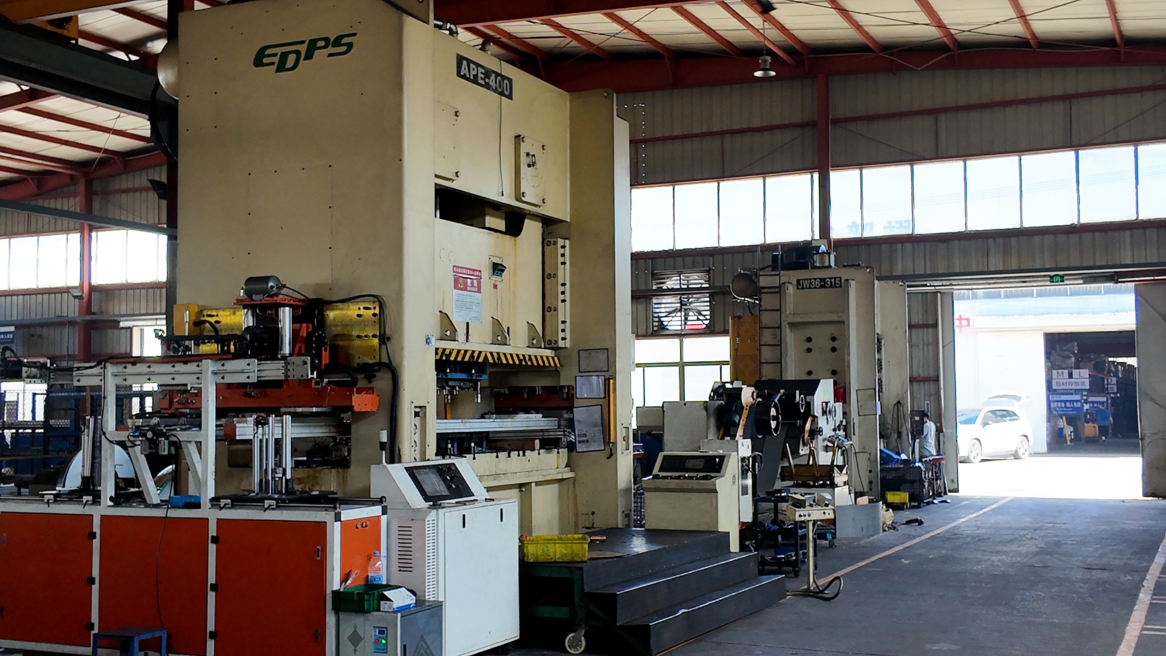
Въпреки че много методи за леене използват специализирана технологична оснастка, терминът "форма" най-често се свързва с леенето под високо налягане. В този контекст дефиниция за прецизно леене под налягане се отнася за процес, при който разтопен метал се впръсква в стоманена форма с висока скорост и под високо налягане, което позволява малки допуснати отклонения и бързи производствени цикли.
Докато продължавате да четете тази статия, ще видите как всеки детайл — от анатомията на матрицата до избора на материали — влияе върху крайния резултат. Ще разгледаме също как контролът на процеса, отстраняването на неизправности и поддръжката играят ключова роля за осигуряване на дългосрочен успех в леенето под налягане.
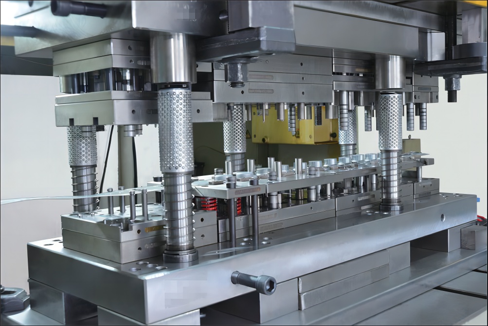
Вътрешна структура и функция на матрицата
Задавали ли сте си въпроса какво всъщност има вътре в една изливна форма матрица, което я прави способна да произвежда толкова сложни и висококачествени метални части? Ако си представяте матрицата просто като блок стомана с кухина, помислете отново. Всяка леечни форми матрица е сложна сглобена конструкция от инженерни елементи, всеки с конкретна роля при оформянето, охлаждането и изхвърлянето на детайла — като същевременно се минимизират дефектите и се максимизира ефективността. Нека преминем през основните компоненти и да видим как те работят заедно, за да превърнат разтопения метал в готови продукти, на които можете да имате доверие.
Основни принципи на геометрията на ядрото и кухината
- Разделителна линия: Интерфейсът, където се срещат двете половини на матрицата, определящия разделянето между страната на капака и избутващата страна. Разположението му влияе както върху лесното премахване на детайла, така и върху местоположението на видимите шевове.
- Кавитет: Отрицателният отпечатък на крайния детайл, обработен с изключителна точност, за да се осигури формата, повърхностното покритие и допуснатите отклонения на детайла.
- Ядро: Вмъквания или пинове, които оформят вътрешни елементи като отвори, ниши или подрязани участъци в детайла. Те могат да бъдат фиксирани или подвижни, в зависимост от необходимата геометрия.
- Вмъквания: Сменяеми секции вътре в полостта или ядрото, често използвани за елементи, склонни към износване, или за сложни детайли.
Канали, врати, вентилационни отвори и преливи
- Гилза: Първоначалният входящ канал за разтопен метал при системи с гореща камера или входът на цилиндъра за изстрелване при матрици със студена камера.
- Рънър: Канали, които насочват разтопения метал от гилзата към полостта, проектирани за балансиран поток и минимална турбулентност.
- Врата: Контролираното отвор, през който металът навлиза в кухината. Неговата форма и размер влияят на скоростта на потока, начина на запълване и риска от улавяне на въздух.
- Вентилации: Малки канали, които позволяват на уловения въздух и газове да избягат, докато металът запълва кухината, предотвратявайки порестост и студени затваряния.
- Преливи: Резервоари или разширения, които събират излишния метал и примеси, осигурявайки само чисти, напълно запълнени части в основната кухина.
Избутващи елементи, плъзгачи и повдигачи
- Избутващи пинове: Стоманени пинове, които избутват затоплената част от кухината след охлаждане. Техното разположение и брой са внимателно подбрани, за да се избегне деформация на детайла или следи по повърхността.
- Плъзгачи: Подвижни секции на матрицата, които създават странични елементи или подрязвания, които не са насочени по посоката на основното отваряне на матрицата. Активират се механично или хидравлично.
- Предпазни елементи: Механизми, които помагат за отделянето на части със сложни форми или вътрешни елементи, често работещи в синхрон с плъзгачите.
Охлаждащи контури и термично управление
- Охлаждащи тръби: Вътрешни канали, циркулиращи вода или масло за бързо отвличане на топлината, осигуряващи равномерно затваряне и намаляване на времето за цикъл.
- Функции за термично балансиране: Стратегическо разположение на охлаждащи и понякога нагревателни елементи за поддържане на оптимална температура на матрицата по време на целия цикъл.
Елементи за подравняване и конструкция
- Ръководни щифтове и втулки: Осигуряват точно подравняване на двете половини на матрицата при затварянето, предотвратявайки образуването на пяна и преждевременно износване.
- Опорни стойки и релси: Усилват конструкцията на матрицата, противодействат на огъването и запазват размерната точност.
- Захващания за закрепване: Фиксират двете половини на матрицата към плочите на машината за леене под налягане.
| Компонент от леене под налягане | Основна цел | Бележки по дизайна |
|---|---|---|
| Линия на разделяне | Разделяне на половините на формата | Местоположението влияе на ръба, флуза и лесното изваждане на детайла |
| Кавитет | Формира външната страна на детайла | Прецизната обработка осигурява качествено повърхностно покритие и допуски |
| Ядро | Създава вътрешни елементи | Може да бъде неподвижна или движеща се; зоните, подложени на износване, могат да използват вметки |
| Канал и гейт | Насочва разтопения метал към кухината | Проектиран за ламинарен поток; избягвайте рязко завъртане и минимизирайте турбуленцията |
| Отвори | Освобождава задържания въздух/газ | Необходим за контрол на порьозността; местоположението се определя въз основа на анализ на потока в калъпа |
| Преливи | Задържат излишния метал и примеси | Разположени така, че да отвличат дефектите далеч от основната част |
| Избутващи щифтове | Избутва отливката | Размер и разположение, за да се избегнат козметични зони; не трябва да деформира детайла |
| Плъзгачи/домкрати | Формира странични елементи/подрязвания | Активира се механично или хидравлично; увеличава сложността на матрицата |
| Охлаждащи канали | Отвежда топлината от матрицата | Критично за цикъла и качеството; трябва да се избягват горещи точки |
| Ръководни щифтове/втулки | Центрира половинките на матрицата | Предотвратява фураж и нецентриране |
Вентилацията и термоконтролът са толкова критични за успеха на отливането, колкото и геометрията — пренебрегването на който и да е от двата фактора може да доведе до дефекти като фураж, залепване или деформации.
Когато разгледате компоненти за пресовка на отливки отблизо ще забележите, че всяка характеристика – независимо дали става въпрос за разположението на вентилационен отвор или контура на канал – влияе пряко върху това как разтопеният метал тече, втвърдява се и се освобождава от матрицата. Например, неправилното вентилиране може да причини задържане на газ и порьозност, докато лошо подравнените ежекторни щифтове могат да оставят следи или дори да напукат детайла. Дизайнът на всеки елемент в форми за ливене на алуминий или други леечни форми е резултат от прецизно инженерство и опит, насочено към получаване на последователни, бездефектни части.
Докато напредваме, ще видим как работата на тези компоненти — особено системите за охлаждане и изхвърляне — оформя целия процес на леене под налягане, влияейки върху скоростта, качеството и общата надеждност на вашата щампа за леене под налягане .
Как матрицата управлява процеса на леене под налягане
Някога се чудили как един масина за дисково ливене преобразува разтопен метал в готова детайл само за няколко секунди? Отговорът се крие в прецизната координация между дизайна на формата, процесната последователност и работата на машината. Нека разгледаме как формата не е просто пасивна матрица — тя е команден център за целия процес на листовото отливане .
От разтопяване до запълване с метал: Цикълът на леене под налягане обяснен
Операция, която се разгръща пред очите ви. Всеки цикъл представлява строго контролирана последователност, при която елементите на формата насочват всяка стъпка: метална отливка операция, която се разгръща пред очите ви. Всеки цикъл представлява строго контролирана последователност, при която елементите на формата насочват всяка стъпка:
- Затваряне на формата: Двете половини на формата се залепват заедно, осигурявайки перфектно подравняване и плътно запечатване.
- Инжекция: Разтопеният метал бързо се впранива в полостта на формата чрез системата на вливник, запълвайки всяка подробност под високо налягане.
- Интензификация: Налягането се поддържа или увеличава, за да се компактира метала плътно, намалявайки порестостта и осигурявайки ясна дефиниция.
- Студене: Каналите за охлаждане в матрицата отвеждат топлина, което осигурява бързо и равномерно затвърдяване на отливката.
- Отваряне на матрицата: След като материалът се затвърди, матрицата се разделя — моментът е критичен, за да се избегнат деформации или залепване.
- Изхвърляне: Избутващите щифтове изтласкват готовата детайл от кухината, готова за рязане и довършване.
- Напръскване/смазване: Повърхностите на матрицата се почистват и смазват, за да се подготвят за следващия цикъл и да се предпазят от износване.
Всеки етап се влияе от вътрешната геометрия на матрицата, системата за охлаждане и механизмите за избутване, което директно влияе на качеството и скоростта.
Гореща камера срещу студена камера: Как се адаптира дизайна на матрицата
Не всички кастинг машини не са еднакви. Изборът между системи с гореща и студена камера формира както матрицата, така и процеса. Ето бързо сравнение:
| Характеристики | Отливане в гореща форма | Леење под налягане със студена камера |
|---|---|---|
| Типични сплави | Цинк, магнезий, олово (ниска точка на стопяване) | Алуминий, магнезий, мед (по-висока точка на топене) |
| Място на топене на метала | Вътре в машината за прецизно леене под налягане (вградена пещ) | Външна пещ, след което се прелива в машината |
| Скорост на цикъла | По-бързо (обикновено по-малко от 60 секунди на цикъл) | По-бавно поради ръчно преливане и по-високи температури |
| Температурно въздействие върху матрицата | По-ниско (удължава живота на матрицата) | По-високо (по-голямо термично напрежение, по-кратък живот на матрицата) |
| Относителен живот на матрицата | По-дълго (по-малко износване) | По-късо (поради сплави за високи температури) |
Матриците за гореща камера са оптимизирани за скорост и дълготрайност, докато матриците за студена камера са проектирани да издържат на по-високи температури и налягане — и двата подхода са от съществено значение в модерното високотоnosно изпъкване под налягане .
Как матрицата управлява времето на цикъла и качеството на детайла
От момента, в който разтопеният метал навлиза в матрицата, до мига, в който детайлът бива изхвърлен, всеки момент има значение. Конструкцията на матрицата — особено размерът на гейта, разположението на отворите за вентилация и ефективността на охлаждането — директно контролира колко бързо и колко добре протича всеки цикъл. Например:
- Конструкция на гейта: Правилно размериран гейт осигурява бързо и равномерно запълване без турбулентности, като с това се минимизират дефектите.
- Вентилация: Правилната вентилация предотвратява задържане на газове и порестост, което е от решаващо значение за плътни и здрави отливки.
- Канали за охлаждане: Ефективното охлаждане намалява времето на цикъла и подобрява размерната стабилност.
Оптимизирането на тези характеристики позволява машини за отливане под налягане да се произвеждат хиляди части с последователно високо качество — което прави прецисното леене предпочтителен метод за автомобилна, аерокосмическа и битова промишленост.
Калъпът е контролна точка за потока, кристализацията и отвеждането на въздуха — никога не е просто пасивен формуляр.
Докато напредвате, ще видите как изборът на материали за калъпа и поведението на сплавта допълнително формират процеса, влияейки върху всичко — от скоростта на цикъла до продължителността на живота на калъпа. Разбирането на тази взаимовръзка е ключово за овладяване на описанието на процеса на прецизно леене от проекта до готовата детайл.
Как изборът на сплав формира процеса на прецизно леене
Алуминиеви системи: течение, свиване и влияние върху дизайна на калъпа
Когато избирате подходящия материал за вашия проект по прецизно леене, сплавта, която избирате, не е важна само поради якостта или теглото — тя фундаментално влияе върху начина, по който самият калъп е проектиран и работи в дългосрочен план. Чудите се защо? Нека го разгледаме, като анализираме двата най-често срещани типа: отливни алуминиеви сплавове и цинкови сплави.
Алуминиевите материали за прецизно леене са ценени заради лекотата си, устойчивостта към корозия и доброто съотношение между якост и тегло. Но знаете ли, че различните алуминиеви сплави — като A380, ADC 10 или Al-Si11Cu3 — имат и уникални свойства, които влияят върху всичко от начина, по който металът се разлива в матрицата, до степента на износване на формата? Например, много алуминиеви сплави притежават висока течливост и могат да запълват тънки и сложни форми, но се свиват при охлаждане, което може да доведе до вътрешни напрежения или порестост, ако не се контролира чрез прецизно разположение на вливниците и ефективно вентилиране (източник) .
- Висока течливост: Алуминиевите сплави (особено тези с по-високо съдържание на силиций) лесно се движат, запълвайки тънки участъци и сложни геометрии.
- Свиване: Очаквайте умерено до високо свиване по време на затвърдяване, което изисква внимателно проектиране на вентилационни отвори и преливи, за да се минимизира порестостта.
- Риск от залепване: Чистото алуминий има тенденция да се залепва за стоманата на формата, но повечето алуминиеви сплавове за прецизно леене съдържат желязо, което намалява залепването и износването на формата.
- Износ на матриците: Алуминият е абразивен, затова при използването му за прецизно леене са необходими инструментални стомани с изключителна устойчивост на топлина и износване — както и редовна поддръжка.
Цинкови системи: Тънки стени, детайли по повърхността и дълготрайност на инструмента
Сменяйки предавките, прецизното леене с цинкови сплави се отличава с възможността да създава изключително тънки стени и остри детайли. Цинковите сплави като Zamak 3, Zamak 5 и Zamak 7 имат по-ниски температури на стопяване и изключителна текучест, което означава, че запълват полостта на матрицата бързо и с по-малко налягане в сравнение с алуминия. Това води до по-дълъг живот на матрицата и по-малък износ, тъй като тя е изложена на по-малко термично и механично напрежение.
- Отлична текучест: Цинковите сплави лесно запълват сложни форми и тънки участъци, намалявайки риска от студени заварки.
- Минимално свиване: По-малко свиване в сравнение с алуминия, поради което порестостта и пукнатините са по-редки.
- Минимално залепване: Цинкът по-рядко се залепва за стоманата на матрицата, което допълнително удължава живота ѝ.
- Изнемогване на долния матрикс: По-ниската температура на стопяване означава по-малко топлинно изтощение и по-дълъг живот на инструмента — идеално за серийно производство.
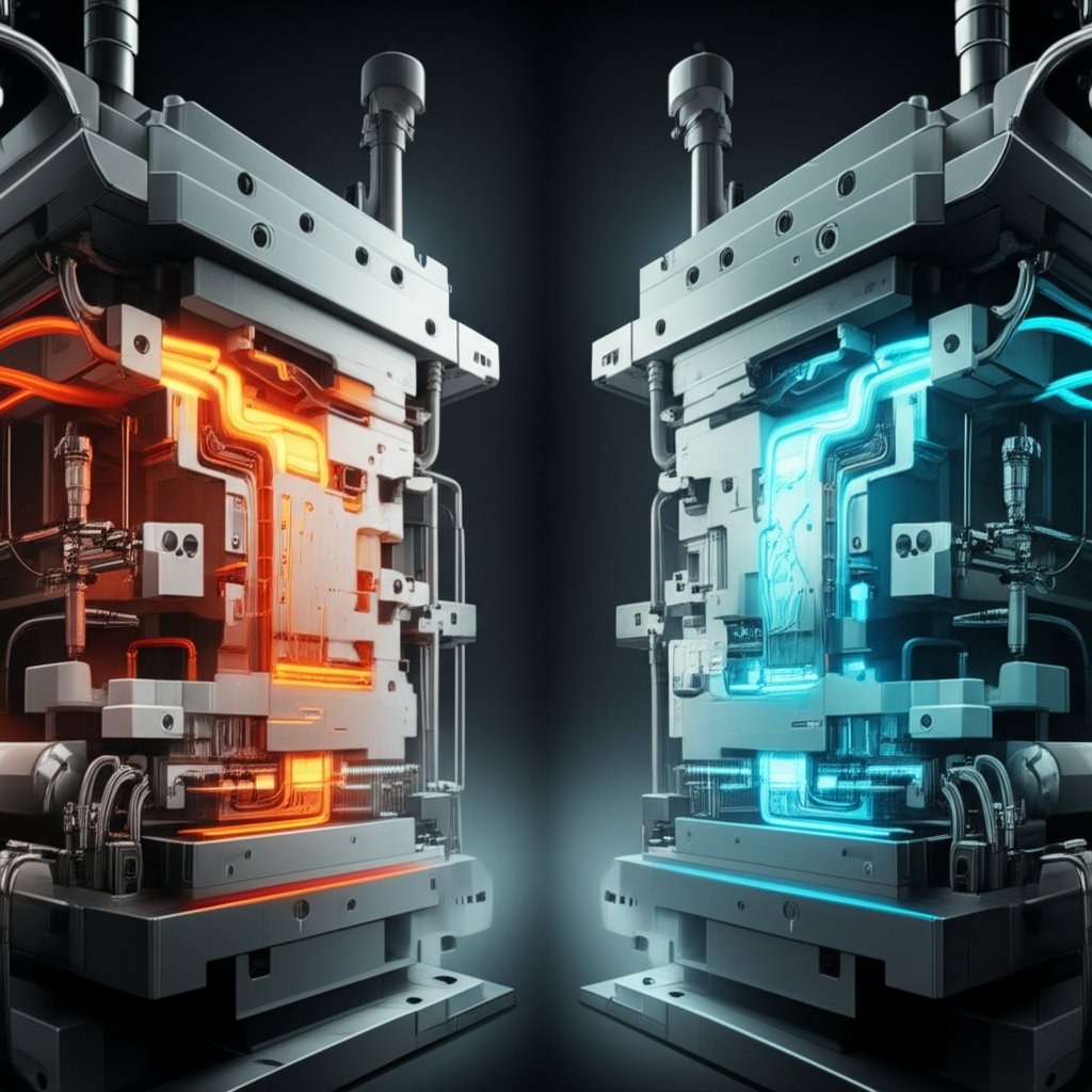
Охлаждане и топлинни градиенти според сплавта
Представете си, че управлявате фабрика за прецизно леене под налягане: Изборът между гравиран алуминий и цинк променя стратегията ви за охлаждане. По-високата точка на стопяване на алуминия изисква по-интензивно охлаждане на матрикса — например плътно разположени канали и бързо течение на вода — за да се намалят циклите и да се предотвратят горещи зони. Цинкът, от друга страна, позволява по-умерено охлаждане и по-щадящо оразмеряване на отдушниците, тъй като се затваря бързо и не напряга матрикса толкова силно.
| ALLOY | Течливост | Риск от порестост | Склонност към залепване | Влияние върху износването на матрикса | Бележка за проектиране |
|---|---|---|---|---|---|
| Алуминиево прецизно леене (A380, ADC 10 и др.) | Висока (особено при сплави, богати на силиций) | Средно до висока | Умерено (намалено поради съдържанието на желязо) | Високо (абразивно, изисква здрава матрична стомана) | Приоритет на здрава вентилация, балансирана система за наливане и интензивно охлаждане |
| Алуминиеви сплави за прецисно леене (Al-Si11Cu3, A360) | Много високо | Умерена | Ниско до умерено | Висок | Използвайте при тънки стени и висока плътност под налягане; контролирайте градиентите на охлаждане |
| Прецисно леене на цинк (Zamak 3, 5, 7) | Отлично | Ниско | Ниско | Ниско (по-дълъг живот на матрицата) | Използвайте възможността за тънки стени и фини детайли; необходимо е по-умерено охлаждане |
Когато изберете материал от лит алуминий или цинкова сплав, не просто избирате метал — вие определяте правилата за изграждане, охлаждане и поддръжка на матрицата. Например, при прецисното леене на алуминий често се изискват високолегирани инструментални стомани, напреднали охлаждащи контури и внимателно проектирана вентилация, за да се управляват свиването и порестостта. Цинкът, благодарение на по-ниската температура на леене, позволява по-дълги производствени цикли, преди да се наложи възстановяване на инструмента.
Поведението на сплавта определя стратегията за охлаждане на матрицата и площта за вентилация колкото и самата геометрия на детайла — направете го правилно и ще повишите както качеството, така и продължителността на живот на матрицата.
Докато напредвате, имайте предвид: вашият избор на сплав оформя целия процес на производство на отливки. В следващия раздел ще разгледаме как се произвеждат и сглобяват матриците, за да отговарят на тези изисквания — осигурявайки, че вашите части работят точно както е предвидено, всеки път.
Как се произвеждат и сглобяват матриците
От блок до прецизно инструмент: Поетапният процес на производство на матрици
Задавали ли сте си въпроса какво е необходимо, за да се превърне един масивен блок инструментална стомана в прецизна матрица, която може да издържи милиони цикли в фабрика за прецизно леене под налягане ? Пътуването от суровината до готовата матрица е прецизен, многоетапен производствения процес на леене процес, който изисква точност на всяка стъпка. Нека разгледаме основните етапи, включени в какво е производството на матрици —и защо всеки детайл има значение за производителността и дълголетието на матрицата.
- Проектиране и инженеринг: С помощта на CAD софтуер инженерите разработват подробни 2D и 3D модели, които определят геометрията, допуските и повърхностните финишни обработки. Този етап изисква плътно сътрудничество, за да се гарантира, че матрицата отговаря на изискванията за детайла и технологичните ограничения.
- Избор на материал: Инструменталните стомани или специални сплави се избират поради тяхната твърдост, якост и устойчивост на топлина. Правилният клас на стоманата осигурява размерна стабилност и дълъг срок на служба.
- Грубо машинно обработване: С помощта на CNC фрезоване и точене стоманеният блок се оформя в основната форма на матрицата, като се премахва излишният материал и се подготвя за по-точни операции.
- Финално машинно обработване и шлифоване: Високоточно фрезоване, точене и шлифоване усъвършенстват повърхностите на матрицата, осигурявайки тесни допуски и гладки повърхности, необходими за качеството на детайлите.
- EDM (Електроерозионно обработване): EDM се използва за създаване на сложни елементи, остри ъгли и дълбоки кухини, които не могат да бъдат достигнати с конвенционално машинно обработване. Прилагат се както методи с потапяне, така и с режеща жица за сложни форми и фини детайли.
- Термична обработка: Матрицата се подлага на термична обработка (гасене, отпускане, нормализация), за да се постигне необходимата твърдост и механични свойства. Контролираното нагряване и охлаждане предотвратява деформации или пукания.
- Полиране и повърхностна обработка: Полират се кухини и ядра до желаната повърхностна обработка, като се премахват следите от електроерозия и се осигурява лесно изваждане на детайлите. Могат да се нанасят повърхностни покрития за допълнителна устойчивост на износване.
- Вложки и охладителни контури: В участъци с голям риск от износване или сложна геометрия могат да се поставят закалени вложки. Охладителните канали се пробиват или обработват чрез машинна обработка за регулиране на топлинните натоварвания по време на производството.
- Сглобяване и подравняване: Всички компоненти на матрицата — половини, плъзгачи, повдигачи, избутвачи — се сглобяват и подравняват. Ръководни щифтове, втулки и опорни колони осигуряват прецизно затваряне и работоспособност.
- Пробни пускания и контрол на качеството: Сглобената матрица минава през сухи пускания и пробни отливки. Проверки за размери, тестове за течове и функционални инспекции потвърждават готовността за производство.
Стратегии за електроерозия и вложки: прецизност там, където е от значение
Когато става въпрос за производство на форми за леене , EDM се отличава с възможността си да произвежда форми и елементи, които традиционната обработка не може да постигне – например тесни ребра, остри вътрешни ъгли или дълбоки, сложни полости. Вметките от своя страна позволяват да се заменят само най-силно износените участъци, удължавайки живота на матрицата и правейки поддръжката по-ефективна.
| Операция | Цел | Типични рискове | Намаляване на риска |
|---|---|---|---|
| Избор на материал | Осигурява дълготрайност и размерна стабилност на матрицата | Неправилният сплав може да причини преждевременен износ или пукнатини | Следвайте стандартите в индустрията (напр. ASM) и изискванията на приложението |
| Груба механична обработка | Формира матрицата до почти окончателните размери | Остатъчно напрежение, деформация | Предвиждайте отпускане на напреженията преди фината механична обработка |
| ЕДМ | Произвежда сложни, прецизни елементи | Микропукалини, шероховатост на повърхността | Използвайте подходяща компенсация за прегаряне; полирайте след EDM |
| Термообработка | Захардява и усилва матрицата | Деформация, пукане | Контролирани цикли на нагряване/охлаждане, инспекция след обработка |
| Сглобяване | Интегрира всички компоненти на матрицата | Неправилно подравняване, течове | Прецизно поставяне, проверка на подравняването, тестване за течове |
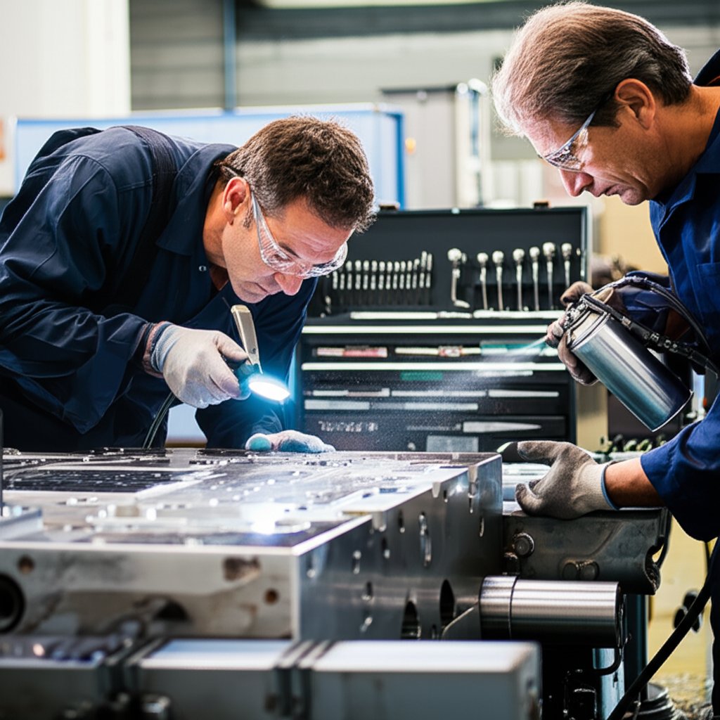
Най-добри практики за подравняване и проба
Окончателната сглобка не е просто съединяване на части — тя има за цел да осигури работата на всичко като система. Неправилно подравняване или несъответстващо прилагане на този етап може да доведе до изтичане на материал, залепване или дори катастрофален отказ на матрицата по време на производство. Затова опитни екипи следват строги протоколи за проба и рутинни инспекции, преди матрицата да бъде използвана в пълномащабно производство.
- Проверете възможността за термично циклиране — уверете се, че каналите за охлаждане са чисти и функционални
- Проверете подравняването на матрицата с водещи щифтове и втулки
- Проверете отворите за вентилация и преливане за правилно отвеждане на въздуха
- Тествайте смазващите системи за плъзгащи се елементи и избутващи щифтове
- Циклирайте избутващата система, за да потвърдите плавно движение и правилна дължина на ход
Контролен списък за проверка преди пускане в експлоатация
- Еднородност на температурата на матрицата (предварително загряване при нужда)
- Подравняване на половинките на матрицата и подвижните компоненти
- Свободни вентилационни отвори и преливници
- Точки за смазване на всички подвижни части
- Избутващите щифтове и плочи се движат свободно
- Охлаждащите контури нямат течове и са тествани за протичане
- Всички фиксиращи елементи са затегнати според спецификациите
Всеки етап от производствения и сглобяван процес на матрицата — от избора на стоманата до окончателното пробно изпитване — директно влияе върху качеството на детайла, живота на инструмента и производителността.
Разбиране как да се направи метална форма е повече от просто оформяне на стомана — това е въпросът за интегриране на инженерни, машинни и контролни по качество процеси в един безпроблемен работен поток. Докато напредвате, имайте предвид, че всеки етап в обработка на матрицата полага основата за успешни, повтарящи се леярски операции и дългосрочна производителност на инструмента.
Отстраняване на дефекти при леене, свързани с формата
Бърза диагностика: От симптом до коренна причина
Когато забележите дефект във вашите детайли, получени чрез леене под налягане , знаете ли къде първо да потърсите причината? Леенето под налягане е прецизен литейен процес , но дори и малки отклонения в дизайна на формата, настройката или контрола на процеса могат да доведат до видими или скрити дефекти. Нека разгледаме най-често срещаните проблеми, техните причини и начина, по който можете да реагирате — стъпка по стъпка.
| Симптом | Вероятни причини | Незабавни действия | Дългосрочна превенция |
|---|---|---|---|
| Порьозност (газова/усукване) | Недостатъчно вентилиране, кратко време на интензификация, затворен въздух, неправилни гейтове | Увеличете времето на интензификация, проверете вентилационните отвори и зоните за преливане, потвърдете целостта на вакуума | Преработете зоната за вентилация, преместете гейтовете, оптимизирайте разположението на разливната система |
| Студени шевове | Ниска температура на метал/форма, ниска скорост на инжектиране, лошо проектирани гейтове, слаба течност на сплавта | Повишете температурата на формата и разтопения метал, умерено увеличете скоростта на впръскване, нагласете размера/местоположението на гейтовете | Оптимизирайте системата за гейтове, използвайте сплави с по-добра течност, оптимизирайте топлинния режим на формата |
| ФЛЭШ | Недостатъчна сила на затваряне, несъосност на формата, износени повърхности на формата, прекомерно налягане на метала | Проверете/настройте тонажа на машината, инспектирайте съосността на формата, почистете разделящите повърхности | Редовна поддръжка на формата, преразработване на линията на разделяне, подобряване на елементите за центриране |
| Леене/залепване на матрицата | Прегрят сплав, повредена повърхност на матрицата, недостатъчен наклон, лошо средство за отделяне | Намалете температурата на разтопяване, поправете/полирайте повърхността на матрицата, подобрете нанасянето на средство за отделяне | Използвайте стомани за матрици с по-добра устойчивост, поддържайте повърхността на матрицата, оптимизирайте системата за избутване |
| Пукалини/горещи пукнатини | Високо вътрешно напрежение, неравномерно охлаждане, неподходяща сплав, неправилно време за избутване | Регулирайте охлаждането и времето за избутване, проверете състава на сплавта | Преразработете за еднородна дебелина на стените, осигурете балансирано охлаждане, използвайте подходящи сплави |
| Угличаване/мехури | Лошо вентилиране, турбулентно течение на метала, излишно смазващо вещество | Увеличаване на вентилационната площ, оптимизиране на скоростта на изстрелване, намаляване на количеството смазка | Подобряване на входа/вентилацията, използване на симулация на потока за валидиране на дизайна |
| Повърхностни дефекти (следи от течение, петна, включвания) | Ниска температура на матрицата, прекомерно количество разделващ агент, лош вход, мръсна повърхност на матрицата | Увеличаване на температурата на матрицата, намаляване на разпръскването, почистване на матрицата, регулиране на скоростта на инжектиране | Подобряване на качеството на повърхността, оптимизиране на модела на разпръскване, поддържане на чистотата на матрицата |
Промени в процеса срещу промени в дизайна на матрицата
Звучи сложно? Не е задължително. Много дефекти в отливен метал могат да бъдат отстранени чрез корекции в процеса — като регулиране на скоростта на изстрелване, температурата на матрицата или модела на разпръскване. Но ако един и същ проблем продължава да се появява, това може да сочи към фундаментален дефект в дизайна на матрицата: недостатъчно големи вентилационни отвори, неправилно разположение на входовете или недостатъчно охлаждане. В този момент е добре да включите инженера по инструменти за по-сериозни промени.
- Корекции в процеса: Регулирайте температурите, скоростите на впръскване или времето за поддържане на налягането; почиствайте и смазвайте повърхностите на матрицата; следете силата на избутване.
- Промени в конструкцията на матрицата: Променете размера и местоположението на отворите/вратовете; преразработете разположението на разливната система; добавете охлаждащи канали или вложки.
Кога да спрете производството
Представете си, че управлявате производство с голям обем с други материали операция. Кога трябва да спрете и да проучите? Ако забележите рязък скок в нивото на брака, повтарящи се пукнатини или порьозност, или внезапна промяна в размерите на детайла, е време да спрете. Продължаването без анализ на основната причина може да доведе до загуба на материали и допълнително повреждане на матрицата.
- Ако дефектите са малки и рядко срещани, регулирайте параметрите на процеса и следете внимателно.
- Ако сериозните дефекти продължават или се влошават, спрете производството и извършете пълна инспекция на матрицата/инструментите.
- Документирайте всички промени и установени неща — тези данни помагат за предотвратяване на бъдещи проблеми и ускоряват отстраняването на неизправностите.
Бързи проверки преди смени за предотвратяване на дефекти
- Проверете вентилационните отвори и преливите за запушвания или износване
- Проверете смазването на матрицата и разпръскването за равномерно покритие
- Уверете се, че температурата на матрицата е в целевия диапазон преди първият изстрел
- Циклирайте избутващите щифтове и плочи за гладко движение
- Потвърдете силата на затягане и подравняването на матрицата на машината
Документирането на промените – по един параметър наведнъж – е ключът към стабилизиране на процеса на прецизно леене под налягане и постигане на последователно качество на детайлите.
Като следвате тези практически стъпки за отстраняване на неизправности, ще намалите не само брака и преработката, но също така ще удължите живота на матрицата си и ще подобрите последователността в производството ви детайли, получени чрез леене под налягане . Следващият път ще разгледаме как да поддържате матриците си в отлично работно състояние на дълга срока чрез умна поддръжка и планиране на жизнения цикъл.
Поддръжка на матрици, износване и планиране на жизнения цикъл
Чести видове износване и откази на матрици
Когато изпълнявате един и същ машина за прецизно леене от ден на ден, ще забележите, че дори и най-здравият стомана за прецесово леене в крайна сметка показва признаци на износване. Но какви са причините за тези проблеми и как можете да ги предотвратите? Нека разгледаме най-честите начини на повреда при материал за матрица за прецизно леене под налягане и какво можете да направите, за да удължите живота на инструмента:
- Износостойкост: Повтарящ се контакт с разтопен метал, особено алуминиеви сплави, износва повърхностите на полостите, каналите и вливните отвори.
- Термична умора: Цикли на бързо нагряване и охлаждане причиняват микропукалини (термични пукнатини), които с времето се разрастват, водейки до пукнатини по повърхността и в крайна сметка до люспене. (справка) .
- Ерозия: Високоскоростният поток от метал, особено при вливните отвори и преливите, постепенно еродира стоманата, което засяга геометрията на детайла и качеството на повърхността.
- Набраздяване и натрупване: Елементи от сплавта (като алуминий) могат да се закрепят и да реагират с повърхността на матрицата, образувайки упорити слоеве, които изискват почистване или дори полиране.
- Пукнатини: Сериозно топлинно или механично напрежение, както и неправилно поддържане, могат да причинят катастрофални пукнатини — понякога довеждайки до край на полезния живот на матрицата.
Представете си един компоненти за алуминиево ливене работи при неконтролирано термично циклиране: ще забележите много по-бързо образуване на пукнатини и ресурсът на инструмента рязко намалява. Затова разбирането на тези режими е първата стъпка към разумното планиране на поддръжката.
Интервали за превантивна поддръжка: Пазете матрицата на машината си в отлично състояние
Редовната, планирана поддръжка е основата за висок добив инструменти за ливене под тиск . Звучи досадно? В действителност прост режим може да предотврати скъпи повреди и да задържи производството ви по график. Ето практически график за поддръжка, който можете да адаптирате за всяка машина за прецизно леене :
| Интервал | Задачи за поддръжка |
|---|---|
| На смяна | Проверете вентилационните отвори и изхвърлящите механизми за запушвания; проверете равномерността на температурата на матрицата; уверете се в смазването на подвижните части; изпробвайте изхвърлящата система |
| Ежедневно | Почистете оловни или други отлагания от кухините; проверете протока и евентуални течове в охлаждащите канали; инспектирайте за нови пукнатини или необичайно износване |
| Седмично | Полирайте повърхностите на кухините при нужда; проверете ориентиращите шипове и втулки; тествайте всички аварийни блокировки и гранични превключватели |
| След X изстрела (напр. 10 000) | Разглобете матрицата за дълбоко почистване; проверете всички вложки и ги заменете при износване; извършете отпускане на напрежението чрез отпускане при температура, ако се препоръчва; прегледайте данните за цикъла за тенденции в производителността |
Редовното поддържане предотвратява превръщането на малки проблеми в големи повреди, спестявайки време и пари.
Поправка срещу Замяна: Вземане на разумни решения за жизнения цикъл
Не всяка дефектност означава, че е време да извадите матрицата от употреба. Много проблеми – като локално запояване, дребни пукнатини или износени избутващи щифтове – могат да бъдат отстранени с поправки на място: TIG заваряване, полирване или замяна на вложки. Но ако забележите обширни пукнатини, сериозна ерозия или повтарящи се повреди на едно и също място, може би е време да замените матрицата или основните ѝ компоненти. Пазенето на подробни протоколи за поддръжка и ремонт ви помага да проследявате моделите на износване и да планирате замяна, преди да настъпи непланиран простоен период.
Контролни списъци за матрицата преди пускане и в края на работната смяна
-
Преди пускане:
- Нагрейте матрицата до целевата температура
- Проверете всички охлаждащи контури за течение и течове
- Проверете вентилационните отвори, преливите и избутващите елементи за наличие на препятствия
- Смажете плъзгачите, повдигачите и движещите се пинове
- Потвърдете, че двете половини на матрицата и вметките са подравнени и здраво закрепени
-
Край на работната смяна:
- Почистете повърхностите на матрицата и премахнете натрупванията от оловно спояване
- Документирайте всякакви нови следи от износване, пукнатини или необичайни събития
- Проверете движението на избутващите елементи и плъзгачите за гладкост
- Прегледайте качеството на детайлите за признаци на дефекти, свързани с матрицата
- Запишете температурата на матрицата и данните за цикъла за анализ на тенденциите
Съвет: Постоянното управление на температурата на матрицата е най-ефективната практика за поддръжка, която удължава живота на матрицата и предпазва качеството на детайлите.
Като следвате тези практически рутинни действия, ще удължите не само живота на вашия машинни матрици , но също така ще увеличите времето на работа и ще намалите отпадъците. Докато преминаваме към следващата секция, ще видите как всички тези стратегии се вписват в по-голямата картина на инструменталната икономика и планирането на разходи за производство с висок обем.
Инструментална икономика и рамка за амортизация на разходи за производствено леене под налягане
Обяснени компоненти на разходите за инструменти
Задавали ли сте си въпроса защо първоначалната цена за персонализиран матричен инструмент може да изглежда висока, дори преди да бъде произведен първият детайл? Причината е, че икономиката на леенето под налягане се основава на високи начални инвестиции, които се изплащат само при големи серийни количества. Нека разгледаме какво влиза в общата цена на един инструмент и как тези разходи повлияват върху всеки отделен детайл, който произвеждате – независимо дали правите няколко стотин или стотици хиляди серийни отливки.
| Компонент на разходите | Еднократно или повтарящо се | Метод на разпределение | Бележки |
|---|---|---|---|
| Проектиране и инженеринг на матрица | Еднократно | На проект/инструмент | 2–3% от общата цена на формата; включва CAD, CAE и анализ на потока |
| Машинна обработка/EDM | Еднократно | На инструмент | До 20% от цената на формата; CNC за грубо обработване, EDM за фини детайли |
| Термообработка | Еднократно | На инструмент | Навършва матрицата за по-дълъг живот; неправилна обработка увеличава риска от износване |
| Опробване и инспекция | Еднократно | На инструмент | 1–2% от цената; покрива пробни пресове, настройки и проверки на качеството |
| Резервни части и вмъквания | Повтарящи се | На партида или по необходимост | Части с предразположение към износване, които се подменят през целия живот на матрицата; планират се предварително |
| Поддръжка и ремонт | Повтарящи се | На изстрел или на смяна | Включва почистване, полирване и дребни ремонти |
| Амортизация на машината | Повтарящи се | На изстрел или на час | Разпределение на машинната цена върху целия ѝ срок на служба и общото производство |
| Материали и отпадъци | Повтарящи се | На детайл | Използването на материала обикновено е 90–95%; количеството отпадъци влияе на цената на детайла |
| Вторични операции | Повтарящи се | На детайл | Отрязване, механична обработка, повърхностно финиране при необходимост |
Амортизация и планиране на обема
Звучи сложно? Нека опростим: инвестициите ви в инструменти са фиксирана разход, който трябва да бъде разпределен върху общия брой детайли, които очаквате да произведете. Колкото повече произвеждате, толкова по-малко "дължи" всеки детайл за цената на матрицата. Ето стъпка по стъпка начин да изчислите желаната амортизация на един детайл — независимо дали сте производител на прецизни отливки, или покупател, сравняващ оферти от производители на прецизни отливки, или услуга за прецизно леене.
- Оценете общата цена на инструментите: Съберете всички еднократни разходи (проектиране, механична обработка, термична обработка, пробни отливки и др.).
- Задайте очакван обем на производството: Решете колко детайла (N) планирате да произведете през целия живот на матрицата.
- Изчислете амортизацията на инструментите на детайл: Разделете общата цена на инструментите на N (Цена на инструменти на детайл = Обща цена на инструменти / N).
- Добавете променливи разходи: За всеки детайл добавете разходите за материали, труд, амортизация на машини, поддръжка и евентуални вторични операции.
- Преглед при етапни точки: Редовно проверявайте реалния обем на производството и нивата на отпадъци. Ако увеличите изхода, цената за детайл намалява; ако произвеждате по-малко детайли, себестойността на детайл расте.
Например, ако общата цена за матрица и настройка е 50 000 долара и планирате да произведете 100 000 детайла, амортизацията на инструмента е 0,50 долара на детайл — преди да добавите разходите за материал и процес. Ако произведете само 10 000 детайла, тази сума наскоква до 5 долара на детайл. Затова при високотонажното производство леенето под налягане превъзхожда по икономическа ефективност.
Фактори за намаляване на себестойността на детайл
Искате ли да извлечете още повече стойност от инвестицията си в матрици? Ето доказани стратегии за намаляване на разходите за детайл и увеличаване на възвръщаемостта, независимо дали управлявате собствени матрици или работите с услуга за леене под налягане:
- Опростяване на геометрията на детайла: Намалете издатините, остри ъгли и ненужни ребра, за да съкратите сложността на матрицата и времето за машинна обработка.
- Използвайте многогнездни или комбинирани форми: Произвеждайте няколко детайла за цикъл, за да разпределите по-бързо разходите за инструменти.
- Повишете използването на материала: Проектирайте литейни канали и врати за минимални отпадъци; рециклирайте излишния метал, когато е възможно.
- Съкратете времето на цикъла: Оптимизирайте охлаждащите канали и термичното управление, за да произвеждате повече детайли на час.
- Намалете нивото на скрап: Използвайте симулации и надеждно отвеждане на газове, за да се минимизират дефектите и преработката.
- Консолидиране на функции: Комбинирайте множество функции в едно единствено леене, за да се намали вторичната механична обработка и сглобяването.
- Планирайте техническо обслужване: Планирайте редовно почистване и смяна на вметки, за да избегнете скъпоструващи прекъсвания в производството.
Инвестирането в здравина на матрицата и термичен контрол често се възвръща чрез по-висока работоспособност, по-нисък скрап и по-стабилно качество — което прави програмата ви за леене под налягане по-конкурентна на дълга сметка.
Като разберете и активно управлявате тези фактори на разходите, ще извлечете максимална полза от инвестицията си в инструменти – независимо дали набавяте от установени производители на прецисни форми или стартирате собствени вътрешни услуги за прецизно леене. Следващата стъпка е да ви помогнем да изберете правилните партньори за нуждите ви от инструменти и производство, осигурявайки безпроблемен преход от проекта до готовата детайл.

Избор на партньори за форми, леене и коване
Какво да търсите при партньор за прецизно леене
Когато търсите алуминиево прецизно леене под налягане oR автоматично спечване компоненти, изборът на правилния партньор може да направи голяма разлика по отношение на качеството, водещото време и разходите. Но какво отличава надежден доставчик от останалите? Представете си, че оценявате кандидати – ето ключовите критерии, които имат най-голямо значение:
- Системи за качество: Търсете партньори със здравословни сертификати (като ISO или IATF 16949) и ясни, документирани процедури за контрол на качеството. Това е от решаващо значение в индустрии като автомобилната и авиационната, където проследяемостта и съответствието са задължителни.
- Възможност за производство на инструменти във фирмата: Доставчиците, които проектират и изграждат собствени матрици, могат по-добре да контролират качеството, да намалят производственото време и бързо да правят итерации в ливене под тискане на алуминиев сплав oR компоненти от цинково леене под налягане .
- Бързина и комуникация: Бързо и ясно обратно съобщение по време на предлагане на оферти, проектиране и отстраняване на неизправности помага да се избегнат скъпоструващи закъснения.
- Логистика и глобално присъствие: Близостта до големи пристанища или ефективни транспортни мрежи може да намали риска и ускори доставката, особено при проекти с голям обем или международно значение.
- Опит във вашия сектор: Доставчиците, запознати със стандарти и изискванията на вашия бранш, са по-добре подготвени да предвидят предизвикателствата и да предложат подобрения в процеса.
Когато коването допълва леенето
Понякога вашият проект може да изисква както леене, така и коване – помислете за структурни автомобилни части, които се нуждаят от точността на леење под налягане срещу прецизно леење методи, плюс якостта на кованите компоненти. Докато формовка под тиск използва многократно използвани стоманени форми за оформяне на разтопен метал под налягане, коването разчита на деформация в твърдо състояние чрез високонапрегнати форми. Принципите на инструментите — прецизност, термичен контрол и повърхностна обработка — са подобни, дори и процесите да се различават.
Ако имате нужда от партньор, който може да осигури и двете, разгледайте доставчици с вътрешен експертен опит по ковашки форми и доказано минало както в леенето, така и в коването. Това гарантира оптимално течение на материала по отношение на якост, тегло и разходи.
Кратък списък с доставчици и следващи стъпки
Готови ли сте да проучите възможностите си? Ето практически препоръчителен списък, който ще ви помогне да започнете. Независимо дали сте в индустрията за алуминиево леене под налягане или търсите напреднали решения за коване, тези ресурси предлагат добър стартиращ пункт:
- Автомобилни ковани части от Шао И : Наши автомобилни ковани части се произвеждат в завода, сертифициран по IATF 16949, което гарантира изключителна якост, дълготрайност и спазване на най-строгите стандарти за качество в автомобилната индустрия. Предлагаме пълно, комплексно производствено решение – от бързо прототипиране и малки пробни серии до напълно автоматизирано масово производство. Чрез собствено проектиране и изработване на прецизни горещи ковашки матрици оптимизираме движението на материала и значително съкращаваме сроковете за доставка. Със стратегическо разположение на само един час от пристанището Нинбо, ние осигуряваме ефективно и надеждно глобално пратене, което ни прави доверен партньор за над 30 автомобилни марки по света.
- Haworth Castings : Специализира се в прецизно леене в пясъчни и гравитационни форми с всеобхватен контрол на качеството и експертиза, насочена към конкретни сектори.
- Zetwerk : Предлага висококачествени стоманени кованите компоненти с управление на проекта от край до край за приложения в автомобилната и промишлената индустрия.
- Ръководства по техниката на леене под налягане и коване : За екипи, които сравняват леење под налягане срещу прецизно леење или изучават ливене под тискане на алуминиев сплав най-добри практики, технически ръководства от стандартизиращи органи (като NADCA или ASM International) предоставят безценен справочен материал.
Близостта на доставчика до големи пристанища или транспортни възли може значително да намали риска от забавяне на доставките — особено при международни или високотонажни поръчки.
Докато напредвате, имайте предвид: най-добрите партньори комбинират технически експертиза, проверени системи за качество и съвместим подход — независимо дали се нуждаете от напреднали алуминиево прецизно леене под налягане или интегрирани автоматично спечване и ковашки решения. Вложете време да проучите кандидатите от краткия си списък, питайте за собствени форми и поискайте препоръки или примери от практиката, за да сте сигурни, че следващият ви проект ще протече гладко от проектирането до доставката.
Често задавани въпроси относно матрици при леене
1. Какво е леене под налягане с простите думи?
Леенето под налягане е производствен процес, при който разтопен метал се впръсква под високо налягане в многократно използвана стоманена матрица, за да се получат бързо детайли с висока точност. Този метод осигурява производство в големи серии с постоянство по отношение на качеството и малки допуски.
2. Как може да се определи дали една част е изработена чрез прецизно леене под налягане?
Частите, произведени чрез прецизно леене под налягане, често имат гладки повърхности, прецизни детайли и видими линии на разделяне, където се съединяват двете половини на матрицата. Може също да забележите малки следи от избутващи щифтове и отрязани врати. Тези характеристики отличават компонентите, получени чрез прецизно леене, от тези, направени с други методи за леене.
3. Каква е основната цел на използването на матрица при леенето?
Матрицата се използва при леенето, за да се създават сложни форми с висока размерна точност и отлична повърхностна обработка. Тя осигурява ефективно течение на материала, контролира топлинния баланс и позволява надеждно избутване, което я прави идеална за масово производство на метални компоненти.
4. В какво се различава прецизното леене под налягане от леенето по загубена форма?
Прецизното леене под налягане използва закалена стоманена матрица за бързо производство под високо налягане на части от нежелезни метали, докато леенето по загубена форма използва унищожима керамична форма за по-широк спектър от метали и по-сложни форми. Прецизното леене обикновено е по-бързо и по-икономично при големи серии.
5. Защо поддържането на матриците е важно в процеса на прецизно леене под налягане?
Редовното поддържане на матриците предотвратява износване, пукнатини и термична умора, осигурявайки постоянство в качеството на детайлите и удължавайки живота на матрицата. Периодични проверки и поддръжка също минимизират простоюването и намаляват дългосрочните производствени разходи.