 Малки порции, високи стандарти. Нашата услуга за бързо проектиране на прототипи прави валидацията по-бърза и лесна —

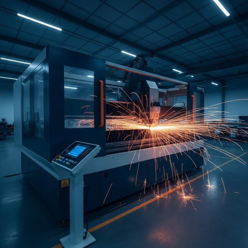
Лазерна рязка на стоманени листове: От суров материал до безупречни готови части
Разбиране на основите на лазерното рязане на стоманени листове
Какво е лазерно рязане и защо е станало предпочитаният метод за обработка на стоманени листове ? На практика лазерното рязане на стоманени листове е термичен процес, при който силно фокусиран лъч светлина разтопява, изпарява или изгаря метала с изключителна прецизност. Самият термин „лазер“ означава Усилване на светлината чрез стимулирано излъчване на радиация — технология, която революционизира обработката на материали след появата си през 60-те години на миналия век.
При рязането с лазер производителите могат да постигнат нива на точност, които традиционните механични методи просто не могат да достигнат. Това прави лазерното рязане на стомана задължителен процес в различни индустрии — от автомобилното производство до архитектурната обработка.
Как взаимодействат лазерните лъчи със стоманата
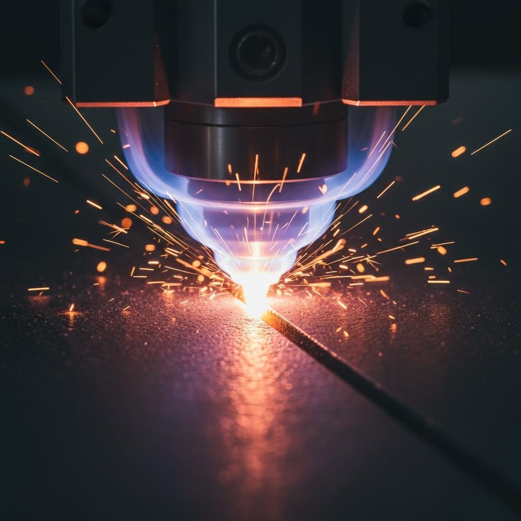
Представете си, че насочвате слънчевата светлина през лупа — сега умножете тази интензивност хиляди пъти. Това по същество се случва при лазерното рязане на листов метал. Когато лазерният лъч достигне повърхността на стоманата, започва fascинираща последователност от физически явления.
Според проучване на ProMetalForm , част от лъчението се отразява от метала, но значителна част се абсорбира и се преобразува в топлинна енергия. Ето какво прави този процес самоподдържащ се: докато температурата на стоманата расте, нейната способност да абсорбира лазерната енергия всъщност се увеличава, създавайки цикъл на положителна обратна връзка, който прави процеса на рязане все по-ефективен след като бъде започнат.
Основните компоненти на лазерното рязане на метал включват:
- Генериране на лъча: Смеси от CO2 газ или влакнооптични системи създават концентриран източник на светлина
- Фокусираща оптика: Лещи или вдлъбнати огледала концентрират лъча в миниатюрен фокус с изключителна плътност на мощността
- Извличане на материала чрез изпарение: Фокусираната енергия загрява, стапя и частично изпарява стоманата в точката на рязане
- Изхвърляне с помощен газ: Коаксиална газова струя отвява разтопения материал, като създава чиста рез
Науката зад термичното рязане
Когато местната температура рязко нарасне в точката на рязане, стоманата преминава през последователни фазови преобразувания. Твърдият метал първо бързо се нагрява, след това започва да се топи. При достатъчно интензивна енергия той може дори директно да се изпарява. При някои високомощни приложения се случва директно сублимиране – стоманата минава директно от твърдо в газообразно състояние, избягвайки напълно течната фаза.
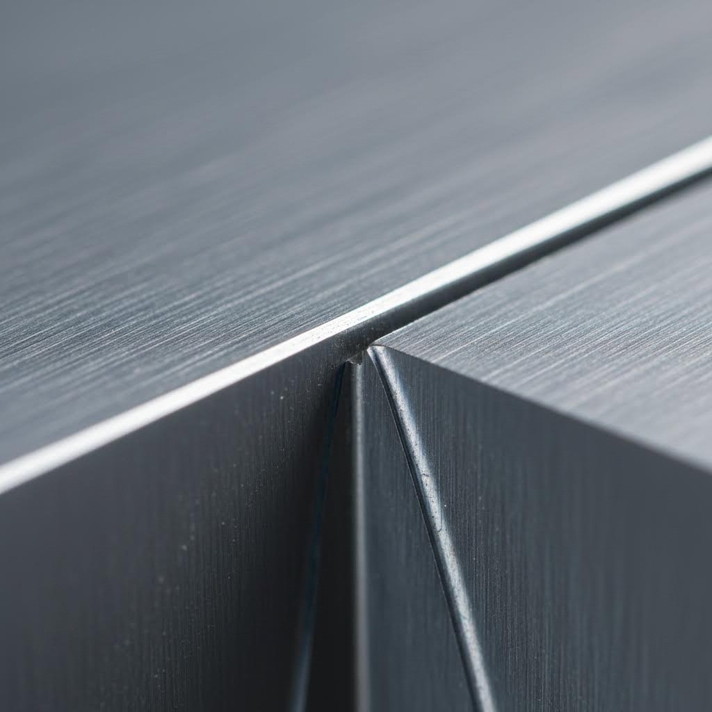
Характеристичната жлебка, образувана по време на този процес, се нарича "рез". Според TWI Global , резът се образува, когато разтопеният материал се отвява от струята на помощния газ. Формата и качеството му зависят от множество фактори: лазерна мощност, скорост на рязане, вид и налягане на газа, както и от специфичните свойства на стоманата.
Два критични фактора определят ефективността на рязането: диаметърът на фокусираното петно и дълбочината на фокуса. По-малките размери на петното осигуряват по-висока плътност на мощността за по-чисто рязане, докато по-голямата дълбочина на фокуса позволява обработката на по-дебели материали с по-добра толерантност към вариации в положението на фокуса. Тъй като тези изисквания са противоречиви, операторите трябва да постигнат внимателен баланс въз основа на конкретната дебелина на стоманата и изискванията за качество за всяка задача.
Разбирането на тези основни принципи осигурява основата за овладяване на по-сложни аспекти на процеса на лазерно рязане — от избора на подходящия тип лазер до оптимизиране на параметрите за конкретни марки стомана.
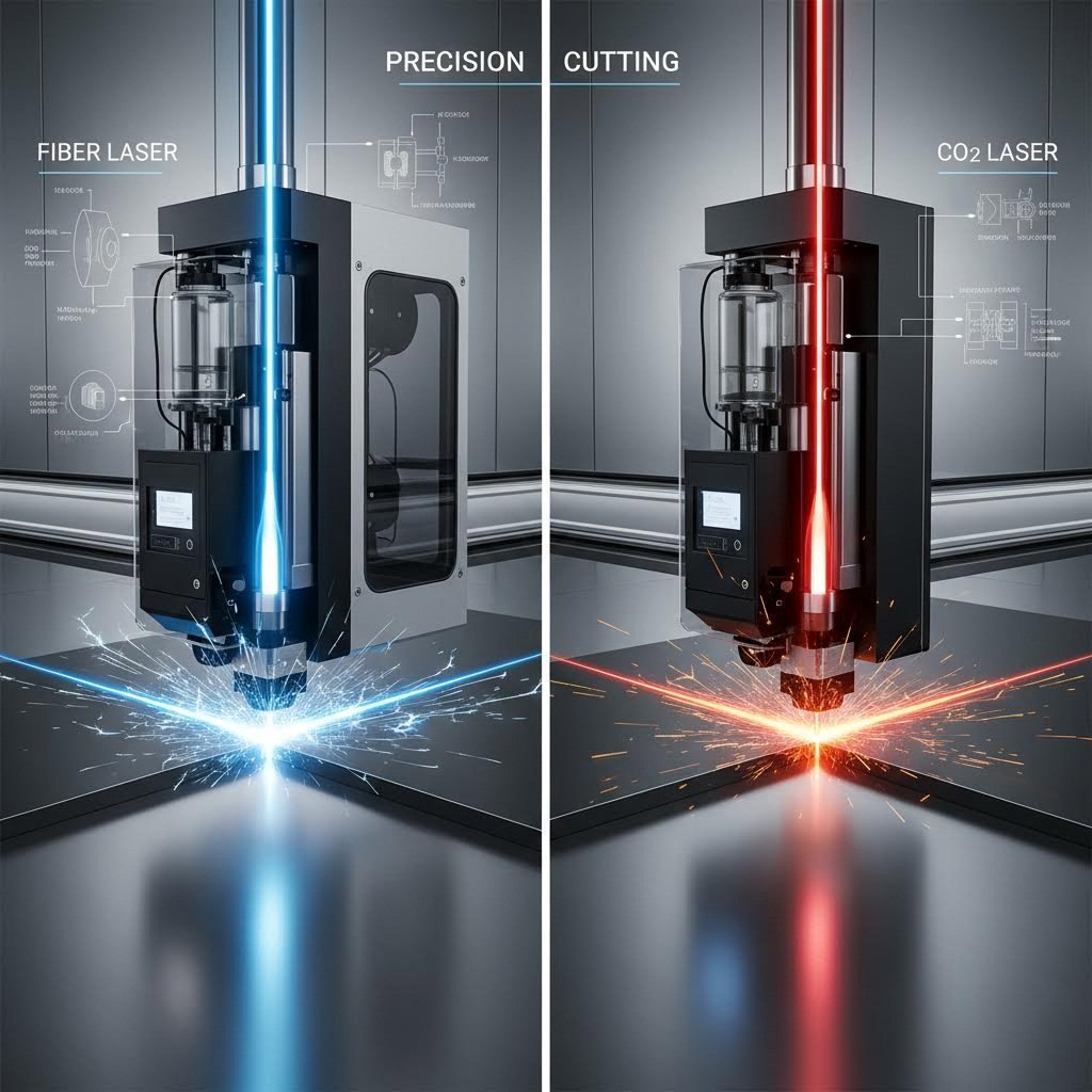
Влакнест лазер срещу CO2 технология за стоманени приложения
Разбирате как лазерните лъчи взаимодействат със стоманата — но кой тип лазер всъщност трябва да използвате? Този въпрос е предизвикал значителни спорове сред производителите, а отговорът силно зависи от конкретните ви изисквания за рязане на стомана. Двете доминиращи технологии — влакнести лазери и CO2 лазери — всяка от тях предлага различни предимства за различни приложения.
Ето в какво е съществената разлика: влакнестите лазери работят на дължина на вълната от приблизително 1,06 микрометра, докато CO2 лазерите произвеждат светлина при 10,6 микрометра. Защо това има значение? Според Bodor laser , металите абсорбират по-късата дължина на вълната на влакнестия лазер значително по-ефективно, което води до по-бързо, по-чисто и по-прецизно рязане на стоманени листове.
Предимства на влакнестия лазер за тънка стомана
При обработка на стоманени листове с дебелина под 6 мм, фибер лазерното рязане доминира в сравнение с конкурентите. Числата разказват убедителна история: машините за фибер лазерно рязане постигат скорост на рязане до три пъти по-висока от еквивалентните CO2 системи при тънки материали. Представете си рязане на неръждаема стомана със скорост до 20 метра в минута — това е продуктивността, която осигурява модерен фибер лазерен рязач.
Какво прави фибер технологията толкова ефективна за тънка стомана? Няколко фактора се обединяват:
- Превъзходно качество на лъча: По-малкият размер на точката създава по-висока плътност на мощността в точката на рязане
- По-добра абсорбция: Стоманата абсорбира по-ефективно дължината на вълната от 1,06 μm в сравнение с по-дългата CO2 дължина на вълната
- Намалени зони с топлинно въздействие: По-бързата обработка означава по-малко топлинно деформиране на тънките материали
- Работа с отразяващи материали: Фибер лазерите се представят отлично при алуминий, мед и месинг — материали, които са предизвикателство за CO2 системите
А Cnc fiber laser cutting machine осигурява и значителни оперативни предимства. Според анализа на EVS Metal за 2025 г., влакнестите системи постигат ефективност при преноса на енергия до 50%, спрямо само 10-15% при CO2 лазери. Това директно се отразява в по-ниски сметки за електроенергия — приблизително 3,50-4,00 щатски долара на час за влакнест лазер спрямо 12,73 щатски долара за съпоставими CO2 системи.
Влакнестият лазерен рязач води и по отношение на поддръжката. Благодарение на твърдотелната технология и по-малкото оптични компоненти, които изискват настройка, годишните разходи за поддръжка обикновено са между 200 и 400 щатски долара, спрямо 1000-2000 щатски долара за CO2 системи. За операции с висок обем при обработка на стомана тези спестявания се увеличават значително с времето.
Когато CO2 лазерите се представят отлично при дебели плочи
Това означава ли, че CO2 технологията е остаряла? Не съвсем. Когато режете стоманени плочи с дебелина над 12 мм, уравнението се променя. Машините за рязане с CO2 лазер осигуряват по-високо качество на ръба при дебели сечения, като произвеждат по-гладки повърхности, които често изискват по-малко последваща обработка.
Физиката зад това предимство се отнася до начина, по който по-дългата вълнова дължина взаимодейства с по-дебели материали. Лъчът с дължина на вълната 10,6 μm разпределя топлината по-равномерно по цялата дебелина на реза, намалявайки шарообразните модели, които могат да възникнат по ръбовете на дебел стоманен материал при използване на влакнест лазер за рязане на метал. При приложения, при които качеството на повърхността е по-важно от чистата скорост на рязане, CO2 системите остават конкурентни.
Според Техническото сравнение на Accurl , CO2 лазерите могат ефективно да обработват материали с дебелина над 20 мм, което ги прави подходящи за производство на тежки конструкции. Технологията запазва предимствата си и при обработка на смесени среди, включващи неметални подложки заедно със стомана.
| Фактор за сравнение | Оптичен лазер | Лазер CO2 |
|---|---|---|
| Дължина на вълната | 1,06 μm | 10,6 μm |
| Оптимална дебелина на стоманата | Под 6 мм (превъзходно), до 25 мм (ефективно) | Над 12 мм (конкурентно), до 40 мм+ |
| Скорост на рязане (тънка стомана) | До 3 пъти по-бързо от CO2 | Базова скорост |
| Енергийна ефективност | 30-50% ефективност при включване към мрежата | 10-15% ефективност при включване към мрежата |
| Часова цена на енергията | $3.50-4.00 | $12.73 |
| Годишна поддръжка | $200-400 | $1,000-2,000 |
| Качество на ръба (тънка стомана) | Отлично, минимални заострености | Добре |
| Качество на ръба (дебела стомана) | Добро, може да се наблюдават ивици | Отлично, по-гладка повърхност |
| Работа с отразяващи метали | Отлична (алуминий, мед, месинг) | Предизвикателство, риск от обратно отразяване |
| Живот на оборудването | До 100 000 часа | 20 000–30 000 часа |
| обща разходна стойност за 5 години | ~$655,000 | ~$1,175,000 |
Пазарната траектория отразява тези технически реалности. Влакнестите лазери в момента притежават приблизително 60% от пазара на лазерна рязка, като приемането им нараства с 10,8–12,8% годишно в сравнение със само 3,1–5,4% за CO2 системите. По-специално при приложения за стоманени листове предимството на влакнестите лазери става още по-изразено – повечето производствени цехове, обработващи предимно стомана, вече са преминали към влакнеста технология поради нейната скорост, ефективност и по-ниски експлоатационни разходи.
Въпреки това, правилният избор изисква честна оценка на вашите конкретни нужди. Каква дебелина на стоманата обработвате най-често? Колко важна е качеството на ръба в сравнение със скоростта на рязане? Какъв е вашият обем на производството? Тези въпроси определят дали влакнест лазерен апарат за рязане или CO2 система по-добре отговарят на вашата дейност – и разбирането на класовете стомана, които ще режете, има също толкова голямо значение при това решение.
Избор на подходящи марки стомана за лазерна обработка
Вече сте избрали лазерната си технология, но дали сте се замисляли дали стоманата ви всъщност е подходяща за лазерно рязане? Не всички стомани се представят еднакво добре под фокусиран лъч. Разликата между безупречно рязане и разочарователен провал често се дължи на избора на материала – ключов фактор, който много производители пренебрегват, докато не възникнат проблеми.
Разбирането на това каква стомана е „с подходяща за лазер“ може да ви спести безброй часове за отстраняване на неизправности и загуба на материал. Нека разгледаме най-важните спецификации и начина, по който различните марки стомана се държат по време на процеса на рязане.
Каква стомана е от качествена лазерна марка
Когато вие осигуряване на стомана за лазерна обработка , три физически характеристики определят успеха: равнинност, състояние на повърхността и допуснати отклонения по дебелина. Защо тези параметри са толкова важни?
Равнинността директно влияе на последователността на фокусиране. Лазерният резач за стомана разчита на поддържането на прецизно фокусно разстояние по цялата повърхност на листа. Според материала на Laser 24, изкривени или извити листове причиняват отместване на фокусната точка, което води до непоследователно качество на рязане, по-големи вариации в ширината на реза и потенциални неуспехи при рязане на по-дебели участъци.
Състоянието на повърхността влияе на първоначалното взаимодействие на лазерния лъч с материала. Тежък окалин, ръжда или замърсяване с масло могат да наруши абсорбцията на лъча, което води до неравномерни резове и прекомерно пръскане. Чисти, еднородни повърхности осигуряват предвидим пренос на енергия от първата милисекунда на рязането.
Допуснатите отклонения в дебелината стават критични при програмиране на параметрите за рязане. Ако вашата „3 мм“ стомана всъщност варира между 2,8 мм и 3,3 мм по цялата площ на листа, параметри, оптимизирани за номиналната дебелина, ще работят неефективно в по-дебелите участъци и потенциално ще изгорят по-тънките зони.
Съпоставяне на видовете стомана с изискванията за рязане
Различните класове стомана представят уникални предизвикателства и възможности за лазерна обработка. Ето какво трябва да знаете за всеки основен вид:
- Мека стомана (S275, S355, CR4): Тези конструкционни класове представляват най-подходящите материали за лазерно рязане на неръждаема стомана. Съдържанието на въглерод обикновено варира от 0,05% до 0,25%, което влияе на твърдостта на ръба след рязане и възможността за образуване на пукнатини по ръба. Класовете S275 и S355, често наричани мека стомана, се различават по границата на овлажняване (съответно 275 N/мм² и 355 N/мм²). Според Laser 24 , тези материали се режат чисто при дебелини от 3 мм до 30 мм с правилната настройка на параметрите. CR4 (Студено обработена стомана, клас 4) осигурява по-гладка повърхност, идеална за видими компоненти, и се реже ефективно при дебелини от 0,5 мм до 3 мм.
- Класове неръждаема стомана (304, 316, 430): Лазерната рязка на неръждаема стомана изисква внимателно отношение към поведението, специфично за всеки клас. Клас 304, най-често срещаната аустенитна неръждаема стомана, предлага отлична устойчивост на корозия и се реже чисто с азотен спомагателен газ за ръбове без оксиди. Клас 316 съдържа молибден за подобрена химическа устойчивост — от решаващо значение за морски и приложения в хранителната промишленост — но по-високото съдържание на никел леко увеличава топлопроводността, което изисква малки корекции на параметрите. Феритният клас 430 съдържа по-малко никел, което го прави по-икономичен, като все пак осигурява добра устойчивост на корозия за архитектурни приложения. Когато имате нужда от лазерен резач за приложения с неръждаема стомана, разбирането на тези различия помага да се оптимизират както качеството, така и разходите.
- Галванизирана стомана (Цинтек, посредством горещо поцинковане): Цинковото покритие, което предпазва от корозия, създава уникални предизвикателства. Според Kirin Laser , цинкът изпарява при около 907 °C — значително под точката на топене на стоманата, като се образуват димове, които изискват подходяща система за отвличане. Цинтек (хладнозавалена стомана с тънко цинково покритие) се нарязва чисто в диапазона от 0,7 мм до 3 мм, докато материали с горещо поцинковане могат да се обработват до 5 мм при подходящо вентилиране. Покритието може да причини леко по-грапави ръбове в сравнение с непокрита стомана, но съвременните влакнести лазери се справят ефективно с тези материали.
- Стойностни нисколегирани стомани (HSLA): Тези инженерни стомани комбинират якост и намалена маса чрез прецизно легиране с елементи като ванадий, ниобий или титан. Лазерното рязане на SS варианти и HSLA класове изисква внимание към зоната, засегната от топлината, тъй като тези материали често се избират точно поради техните механични свойства. Твърде голям топлинен вход може да промени внимателно контролираната микроструктура, която осигурява предимството на HSLA стоманите — високо съотношение между якост и тегло.
Освен избора на клас, помислете как избраният Ви материал ще се представя в целия производствен процес. Стомана, която се нарязва прекрасно, може да създаде предизвикателства по време на последващи операции като огъване, заваряване или довършителна обработка. Взаимодействието между параметрите за лазерно рязане и свойствата на материала отива зад рамките на самата рязална маса – затова разбирането на ключовите параметри за рязане става следващата Ви важна стъпка към последователни и висококачествени резултати.
Ключови параметри за рязане и фактори за прецизност
Избрали сте подходящата лазерна технология и сте осигурили качествена стомана – но как всъщност настройвате параметрите, които дават безупречни резове? Точно тук много оператори изпитват затруднения и именно тази липса на знания разделя средните резултати от изключителните. Разбирането на взаимовръзката между мощността, скоростта и позицията на фокусиране превръща машината за рязане на стомана от скъп инструмент в прецизно устройство.
Ето истината: прецизността при лазерното рязане зависи от съвместната работа на множество променливи. Твърде голяма мощност води до прекомерни топлинно засегнати зони и натрупване на шлака. Твърде малка оставя незавършени резове. Скорост, която е твърде висока, причинява грапави ръбове; твърде ниска – изгаряния и загуба на материал. Нека разгледаме тези взаимоотношения, за да можете да оптимизирате машината си за лазерно рязане на стомана за всяка област на приложение.
Настройки на мощността според дебелината на стоманата
Основното правило е просто: по-дебелата стомана изисква по-голяма мощност. Но връзката не е напълно линейна и разбирането на нюансите помага да изберете правилното оборудване и да оптимизирате съществуващите системи.
Според графиците за скорост на Hytek Tools, изискванията за мощност на влакнестия лазер нарастват предвидимо с дебелината на материала. Лазер с мощност 3 kW ефективно обработва тънки стоманени листове, докато рязането на плочи над 20 мм изисква източници на мощност от 12 kW или повече. Ето практическа рамка за приложения за лазерно рязане на стоманени листове:
| Дебелина на желяза | Препоръчителна мощност | Диапазон на скоростта на рязане | Позиция на фокуса |
|---|---|---|---|
| 0,5–1,0 mm | 1–2 kW | 15–30 m/min | На повърхността до +0,5 мм над |
| 1,0–3,0 мм | 2–3 kW | 8–20 м/мин | На повърхността до -0,5 мм под |
| 3,0–6,0 мм | 3–6 кВт | 3–10 м/мин | -1,0 до -2,0 мм под повърхността |
| 6,0–12,0 мм | 6–12 кВт | 1–4 м/мин | -2,0 до -4,0 мм под повърхността |
| 12,0–20,0 мм | 12–20 кВт | 0,5–1 м/мин | -4,0 до -6,0 мм под повърхността |
| 20,0–30,0 мм | 20–30 кВт | 0,3–1 м/мин | -6,0 до -8,0 мм под повърхността |
Забележете как фокусната позиция се премества по-дълбоко в материала с увеличаване на дебелината. Това компенсира геометрията на реза — по-дебелите материали изискват фокусната точка на лъча да бъде позиционирана под повърхността, за да се запази режещата енергия през цялата дълбочина. Неправилният избор е честа причина за непълни резове и прекомерно образуване на капчици по долните ръбове.
Разликите в топлопроводността между видовете стомана също влияят на избора на параметри. Неръждаемата стомана провежда топлина приблизително с 30% по-неефективно в сравнение с меката стомана, което означава, че задържа енергията по-дълго време в зоната на рязане. Това позволява леко по-високи скорости на рязане при неръждаема стомана при еквивалентни дебелини — но също увеличава риска от топлинна деформация, ако параметрите не са внимателно балансирани.
Оптимизиране на скоростта за чисти ръбове
Звучи сложно? Връзката между скорост и качество всъщност следва интуитивни принципи, когато разберете основната физика. Според Подробния наръчник на DW Laser , скоростта определя как се разпределя топлината в зоната на рязане.
По-високите скорости разпределят топлинната енергия по-равномерно, предотвратявайки локално прегряване, което причинява изгаряния и прекомерно оксидиране. По-ниските скорости концентрират топлината, осигурявайки по-чисто оформяне на реза — но ако скоростта е твърде ниска, ще се получат широки термично засегнати зони с оцветени ръбове и възможни металургични промени.
Намирането на оптималния баланс изисква разбиране на тези ключови принципи:
- Важна е сложността на дизайна: Сложни модели с тесни ъгли изискват по-бавни скорости, за да се запази точността — лазерната глава трябва да забави ход, да задържи позицията при смяна на посоката и след това да ускори отново
- Еднородността на материала влияе върху толерантността към скорост: Еднаква дебелина позволява постоянна скорост; вариациите изискват или по-консервативни параметри, или адаптивни системи за управление
- Изискванията за качество на ръба определят избора на скорост: Декоративни части, нуждаещи се от безупречни ръбове, оправдават по-бавни скорости, докато структурни компоненти могат да допуснат по-бързо рязане с малко грапавост по ръба
- Налягането на помощния газ взаимодейства със скоростта: По-високо налягане на газа позволява по-бързо рязане, като по-ефективно отстранява разтопения материал от процепа
При оценката на услуги за прецизно лазерно рязане или при изчисляване на разходите за лазерно рязане за проект, имайте предвид, че по-тесните допуски обикновено изискват по-бавни скорости на рязане – което директно влияе на цикъла и разходите. Този компромис между скорост и прецизност е основен за икономиката на лазерното рязане на стоманени листове.
Постижими допуски и позиционна точност
Каква прецизност всъщност може да очаквате от лазерно изрязани стоманени части? Според Техническите спецификации за допуски на TEPROSA лазерното рязане постига забележителна размерна точност, но допуските силно зависят от дебелината на материала и възможностите на машината.
Стандартният отраслови референтен документ е DIN ISO 2768, който дефинира класове на допуски – от фин (f) до много груб (sg). Повечето прецизни услуги за лазерно рязане произвеждат според DIN ISO 2768-1 m (среден клас на допуски) като база. Ето какво означава това на практика:
- Размери до 6 мм: постижим допуск ±0,1 мм
- Размери 6–30 мм: типичен допуск ±0,2 мм
- Размери 30–120 мм: ±0,3 мм стандартен допуск
- Размери 120–400 мм: ±0,5 мм очакван допуск
Няколко фактора влияят върху това дали ще постигнете по-тесния край на тези диапазони. Позиционната точност на машината — колко точно следва рязещият глава зададените пътища — обикновено е в диапазона от ±0,03 мм до ±0,1 мм при съвременните CNC системи. Въпреки това, тази механична прецизност се превръща в точност на детайла само при правилна оптимизация на параметрите, качествен материал и стабилни топлинни условия.
Допуските за равнинност следват отделни стандарти. DIN EN ISO 9013 дефинира изискванията за качеството при термично рязане, докато спецификациите за материали като DIN EN 10259 (валцовани на студено листове) и DIN EN 10029 (валцовани на горещо листове) установяват допустими отклонения в равнинността на самия начален материал. Дори перфектното лазерно рязане не може да коригира проблеми с равнинността, присъстващи в суровия стоманен лист.
Колкото по-дебел е Вашият материал, толкова по-предизвикателно става спазването на тесни допуски. Ширината на рязане се увеличава с дебелината, а ъгълът на рязане (лекият конус от горната към долната повърхност) става по-изразен. За критични приложения, изискващи изключителна прецизност при лазерно рязане, посочете по-строги класове на допуски от самото начало — имайки предвид, че това може да повлияе както на времето за обработка, така и на разходите.
С мощността, скоростта и фокуса, оптимизирани за конкретната дебелина на Вашия стоманен материал и изискванията за качество, остава един критичен променлив фактор: помощният газ, който отстранява разтопения материал и формира ръбовете на рязането. Този често пренебрегван фактор може да бъде решаващ между задоволителни резултати и наистина висококачествени ръбове.
Избор на помощен газ и оптимизация на качеството на ръба
Настроихте си параметрите за мощност и скорост на рязане, но какво да кажем за невидимия партньор, който прави възможни чистите резове? Помощният газ не е просто поддържащ елемент при лазерното рязане на стоманени листове; според The Fabricator той е „повече партньор, отколкото помощник, работещ в синхрон с лазерния лъч“. Въпреки това, изненадващо много оператори пренебрегват този критичен фактор, когато отстраняват проблеми с качеството на рязане.
Ето какво се случва при всеки лазерен рез: фокусираният лъч разтопява стоманата, а помощният газ издухва разтопения материал от процепа, като едновременно влияе на химичната реакция в зоната на рязане. Изберете грешен газ или грешно налягане и ще имате проблеми с остатъци от разтопен материал, окисляване и непоследователни ръбове, независимо колко перфектно сте оптимизирали другите параметри.
Рязане с кислород за скорост и икономичност
При рязане на мека стомана и въглеродна стомана кислородът осигурява нещо, което никакъв друг помощен газ не може: екзотермична реакция, която всъщност помага за рязането на материала. Според Bodor laser , кислородът извършва приблизително 60 процента от работата по рязане на тези материали, което обяснява защо позволява по-високи скорости на рязане с относително ниска лазерна мощност.
Как работи това? Когато високочист кислород дойде в контакт с разтопена стомана, се получава реакция на горене, която генерира допълнителна топлинна енергия. Тази допълнителна енергия ефективно увеличава способността на лазера за рязане, като ви позволява да обработвате по-дебели плочи от въглеродна стомана, отколкото би било възможно при дадена мощност.
Компромисите са ясни:
- Предимства: Висока скорост на рязане, отлична проникваща способност при дебели плочи, по-ниски изисквания за лазерна мощност, икономично потребление на газ
- Ограничения: Създава оксидирани (потъмнели) ръбове от рязане, които може да изискват шлайфане преди заваряване или боядисване
- Оптимални приложения: Строителна стомана, плочи от въглеродна стомана 6 мм и по-дебели, производство с висок обем, където скоростта е по-важна от качеството на ръба
Чистотата на кислорода има голямо значение. Според експерти в индустрията, качеството на рязане рязко намалява, когато чистотата падне под 99,7% — почти напълно ще спрете рязането. Типичните настройки за налягане са около 28 PSI или по-ниски, с дебит под 60 стандартни кубични фута в час. Твърде много кислород създава прекалено широко екзотермично реакция, което води до груби, неравномерни ръбове.
Азот за ръбове без оксиди
Нуждаете ли се от части, готови за заваряване или боядисване без вторична обработка? Азотът е вашият отговор. Като инертен газ, азотът изцяло предотвратява оксидацията и произвежда ярки, чисти ръбове, които не изискват последваща обработка след рязане.
Механизмът на рязане се различава принципно от рязането с кислород. Вместо да изгаря материала, азотът просто предпазва разтопената стомана от атмосферния кислород, докато високото налягане изхвърля разтопения метал извън процепа. Според FINCM , това води до "гладки, ярки ръбове без загрубяване."
Рязането с азот е превъзходно за:
- Неръжавееща оцел: Предотвратява окисляването на хрома, което би нарушило корозионната устойчивост
- Алуминий: Създава чисти ръбове без оксидния слой, който пречи на заварката (бележка: въпреки че тази секция се фокусира върху стомана, същите принципи важат и когато лазерният рязач се използва за алуминий и се изискват безупречни ръбове)
- Видими компоненти: Архитектурни елементи, декоративни части или всякакви приложения, при които външният вид има значение
- Предварително боядисана или покрита стомана: Минимизира повреди по ръбовете, които биха могли да нарушат защитните покрития
Разходите са значителни. Рязането с азот изисква високо налягане (често 150–300 PSI) и високи скорости на подаване, като консумира значително повече газ в сравнение с рязането с кислород. При дебела неръждаема стомана разходите за азот могат да представляват сериозна част от разходите за обработката на отделна детайл. Въпреки това, премахването на вторична финишна обработка често прави азота по-икономичния избор, когато се вземат предвид общите производствени разходи.
Компресиран въздух като икономична алтернатива
Ами ако можеше да използвате по-голямата част от предимствата на азота при значително по-ниска цена? Компресиран въздух – съдържащ приблизително 78% азот и 21% кислород – предлага точно този компромис за определени приложения.
Според техническия анализ на Bodor, компресираният въздух работи добре за алуминиеви листове, галванизирана стомана и материали с малка до средна дебелина, когато изискванията за качеството на ръба са умерени. Малката примес на кислород всъщност благоприятства рязането на алуминий, като осигурява „малко допълнително усилие“, което подобрява външния вид на ръба.
Икономическите предимства са убедителни: въздухът може да се произвежда на място с помощта на стандартни компресори, като се елиминират закупуването на бутилки, нуждата от складиране и доставките. За операции, при които се режат предимно тънки материали и външният вид на ръба не е от решаващо значение, използването на компресиран въздух значително намалява експлоатационните разходи.
Въпреки това съществуват ограничения. Съдържанието на кислород може да причини частична оксидация на ръба — не толкова сериозна, колкото при рязане с чист кислород, но забележима в сравнение с азотно рязане. Въздухът също изисква високо налягане и голям дебит за чисто рязане, което означава, че стандартният компресор в работилницата може да не осигури достатъчен обем. Според отраслови източници първоначалните разходи за специализирано оборудване за подготвка на въздух могат да са значителни.
| Вид газ | Най-добри приложения | Качество на ръба | Влияние върху скоростта на рязане | Разходи |
|---|---|---|---|---|
| КИСЛОРЪД (O₂) | Въглеродна стомана, конструкционна стомана, дебели плочи (6 мм+) | Оксидирани/потъмнели ръбове; може да се наложи последваща обработка | Най-бързо при въглеродна стомана поради екзотермичната реакция | Ниско газово потребление; икономична цена на рязане |
| Азот (N₂) | Неръждаема стомана, висококачествени части, видими компоненти | Ярка, без оксиди, готова за заваряване повърхност | По-бавно при дебели плочи; конкурентно при тънки материали | Високо потребление; по-висока цена на рязане; премахва необходимостта от вторична обработка |
| Сжат въздух | Алуминий, поцинкована стомана, тънки до средни плочи | Умерен; възможна е някоя и друга оксидация | Подходящ за тънки материали; не е идеален за дебели сечения | Най-ниска експлоатационна цена; възможна е генерация на място |
Настройки на налягането и оптимизация на дюзите
Изборът на правилния газ е само половината от уравнението — правилното му подаване довършва картината. Според Задълбочен анализ на The Fabricator , проблемите с помощния газ са сред най-честите причини за лошо качество на рязане, въпреки че много оператори изцяло ги пренебрегват.
Налягането и скоростта на потока работят заедно, но имат различни цели. Налягането осигурява силата, която отстранява разтопения материал от процепа, докато скоростта на потока гарантира достатъчен обем газ да достигне зоната за рязане. Само увеличаването на налягането няма да реши проблемите, ако вашата система за подаване създава ограничения за потока.
Диаметърът на дюзата значително влияе върху двата параметъра. Ето ключовият момент: когато увеличите диаметъра на дюзата дори с половин милиметър, приблизително удвоявате скоростта на газовия поток. Дюза с диаметър 2,5 мм може да изисква 2000 кубични фута в час, докато дюза с 3,0 мм изисква около 3500 кубични фута в час. Тази зависимост често изненадва много оператори — диаметърът на дюзата е на втора степен в изчисленията на дебита, което означава, че малки промени водят до големи ефекти.
При приложения с фибри лазери и характерните им тесни резове, по-големите дюзи често дават по-добри резултати, отколкото бихте очаквали. Физиката включва триене между бързо движещия се помощен газ и неподвижния околен въздух по ръбовете на стълба. При тесни газови стълбове тази турбулентност може да проникне в реза и да причини неравни рязания. По-широките газови стълбове задържат турбулентната зона на разстояние от зоната за рязане, като позволяват на централния газов поток да навлезе в реза без смущения.
Практическите насоки за налягане се различават според приложението:
- Рязане с кислород на въглеродна стомана: 10-28 PSI, поток под 60 SCFH
- Рязане на неръждаема стомана с азот: 150-300 PSI, високи скорости на потока, скалирани според дебелината на материала
- Смestоен въздух: Подобно на изискванията за азот; уверете се, че капацитетът на компресора отговаря на нуждите
При отстраняване на проблеми с качеството на ръба, имайте предвид цяката газова линия за подаване – от резервоара или компресора през тръбопроводите, регулаторите и фитингите до дюзата. Всеки точка на свързване, особено където диаметърът на тръбопровода се променя, може да създаде ограничения в потока, които лишават зоната за рязане от необходимия обем газ. Операторите често компенсират, като увеличат налягането, но отстраняването на основните ограничения в потока осигурява по-добри резултати.
С оптимизиран избор и подаване на помощен газ сте отстранили основните технологични променливи. Но какво да кажем за самите детайли? Проектирането на компоненти специално за лазерна рязка — разбирането на минималните размери на елементите, топлинните аспекти и използването на материала — може да означава разликата между детайли, които се режат безупречно, и проекти, които противодействат на процеса на всяка крачка.
Ръководство за проектиране на стоманени компоненти за лазерна рязка
Оптимизирахте лазерните си параметри и избрахте идеалния помощен газ — но какво се случва, когато дизайна на детайла Ви работи срещу процеса? Дори най-модерната машина за рязка на метал не може да преодолее фундаментални проектирани ограничения. Истината е, че детайлите за лазерна рязка, които изглеждат страхотно в CAD софтуера, не винаги се превръщат в безпроблемни физически компоненти. Разбирането на проектантските ограничения преди рязката спестява материал, време и раздразнение.
Помислете за това по следния начин: машината за рязане на метал следва програмирани пътища с изключителна прецизност, но все пак важат физичните закони. Температурата се разпространява, тънките елементи се деформират, а малките отвори могат да се затворят поради топлинно разширение. Нека разгледаме правилата за проектиране, които гарантират, че вашите лазерно изрязани метални листове ще бъдат точно каквито сте замислили.
Минимални размери на елементи, които се режат чисто
При проектирането на проекти за рязане на листов метал, успехът или провалът зависят от размера на елементите спрямо дебелината на материала. Според ръководството за проектиране на Komacut, използването на стандартни дебелини на материала е един от най-лесните начини за оптимизиране на процеса — лазерните резачи са калибрирани за тези размери, което ги прави по-икономични и лесно достъпни.
Ето основния принцип: минималният диаметър на отвора трябва да бъде равен или по-голям от дебелината на материала. Лист от стомана с дебелина 3 мм може надеждно да образува отвори с диаметър 3 мм, но опитите за изработване на 2 мм отвори са с риск от непълно рязане, слети ръбове или деформирана геометрия. При по-тънки материали под 1 мм понякога е възможно това съотношение да се промени леко, но изпитването е задължително.
- Минимален диаметър на отвор: Равно на или по-голямо от дебелината на материала (минимално съотношение 1:1)
- Разстояние от дупка до ръб: Поне два пъти дебелината на листа, за да се предотврати разкъсване на ръба по време на рязане или последващи операции по формоване
- Разстояние между отделни елементи: Според MakerVerse , разполагайте геометрията за рязане на разстояние поне два пъти дебелината на листа, за да се избегне деформация
- Минимална ширина на процеп: Равно на дебелината на материала; по-тесни процепи имат риск от термично заваряване по време на рязане
- Радиуси на ъглите: Остри вътрешни ъгли концентрират напрежението — добавете минимален радиус от 0,5 мм за конструкционни части
- Ширина на езика и микрорелсовото съединение: Обикновено 0,3–1,0 мм в зависимост от материала; ако е прекалено тънко, частите падат преждевременно, а ако е прекалено дебело, премахването става трудно
Защо тези правила са важни? При лазерната рязка на метални листове ширината на рязане обикновено варира от 0,1 мм до 1,0 мм в зависимост от материала и параметрите. Елементи, по-малки от това, просто не могат да се оформят правилно — лъчът премахва повече материал, отколкото съдържа елементът. Дори малко по-големи елементи могат да пострадат от топлинна деформация, когато топлината се концентрира в малки области.
Проектиране за топлинна стабилност
Топлината е едновременно инструмент и враг при лазерната обработка. Според Техническия анализ на SendCutSend , зоната, засегната от топлина (HAZ), е „частта от метала около линията на рязане, която е променена от интензивната топлина, но не е напълно разтопена“. Признаците включват дъговидно оцветяване, увеличена твърдост и крехкост, както и микроскопични пукнатини, които могат да се разпространяват под натоварване.
За прецизни приложения, ЗТВ създава зони с непредвидима якост. Микроструктурата се променя перманентно, когато метала надвиши температурата си на трансформация, и тези промени остават след охлаждането. Това е особено важно за:
- Аерокосмически и конструкционни компоненти: ЗТВ в критични области е свързвано с повреди по време на полет
- Части, изискващи последващо заваряване: Променената микроструктура влияе на качеството на заварката и якостта на съединението
- Прецизни механични сглобки: Наведрените ръбове могат да се напукат по време на огъване
- Декоративни елементи: Оцветяването изисква допълнителна обработка за отстраняване
Минимизирането на деформациите при тънки материали изисква стратегическо проектиране. Когато работите със стомана под 2 мм, натрупването на топлина се случва бързо, защото има по-малко маса за абсорбиране на топлинната енергия. Помислете за следните подходи:
- Разпределете рязанията по цялата ламарина: Вместо да се изрязват всички елементи в една област преди преминаване напред, програмирайте последователността на рязане така, че топлинният вход да се разпределя по цялата детайл
- Добавете жертвени фланци: Малки съединения към заобикалящия скелет задържат детайлите плоски по време на рязане, предотвратявайки деформация от термичен стрес
- Избягвайте дълги, тесни геометрии: Тесни ивици, успоредни на линиите на рязане, натрупват топлина и се деформират; уголемявайте тези области, когато е възможно
- Помислете за посоката на рязане: Според проучвания в индустрията, започването на рязане от центъра на листа и придвижване навън помага за по-добро управление на разпределението на топлината
Съвет за проектиране: Еднакъв радиус на огъване и насоченост намаляват производствените разходи значително – нееднозначни спецификации означават повече препозициониране и по-дълги цикли
Ефективност при подреждане и използване на материала
Умното проектиране не свършва с отделните детайли, а продължава до начина, по който те се подреждат върху лист. Разходите за материал често представляват най-голямата статия за разходи при проекти за лазерно рязане, което прави ефективността при подреждане критичен икономически фактор.
Ефективното гнездене започва още в проектантската фаза. Детайлите с допълващи се геометрии — при които вдлъбнатият профил на един елемент се поставя в изпъкналата ръб на друг — значително подобряват използването на материала. Според Komacut, изборът на 3 мм стомана вместо нестандартна дебелина от 3,2 мм позволява да се избегнат минимални поръчки от дузини или стотици листа, забавяния от седмици и значително по-високи цени.
- Проектирайте детайли с общи ръбове, когато е възможно: Общите линии на рязане намаляват както времето за рязане, така и отпадъците от материал
- Имайте предвид посоката на зърното: За детайли, които изискват последващо огъване, ориентирайте проектите с оглед на зърнестостта на материала
- Предвижда се място за ширината на рязане при плътно гнездене: Имайте предвид, че при всяка линия на рязане се губят 0,1–1,0 мм материал
- Групирайте детайли с еднаква дебелина: Обработката на всички 3 мм детайли преди преминаване към суровина от 5 мм минимизира времето за настройка
Важно е и отношението между проектните решения и последващите операции. Ще изискват ли изрязаните с лазер части огъване, заваряване или повърхностно финализиране след това? Ако отворите са разположени твърде близо до ръбовете, Makerverse отбелязва, че "вероятността от разкъсване или деформация на отвора е по-висока, особено ако частта по-късно премине през формоване". Проектирането с оглед на целия производствен процес — от суровия стоман до готовия компонент — гарантира, че всяка операция ще бъде успешна, без да компрометира следващата.
След като внимателното проектиране заложи основата за успех, следващото предизвикателство е постигането на последователно високо качество на ръбовете при всеки един компонент. Разбирането какво влияе на изрязаните ръбове — и как да се отстраняват типични проблеми — превръща добри резултати в изключителни.
Постигане на изключително високо качество на ръбовете при рязане на стомана
Оптимизирахте параметрите си, избрахте подходящият газ за подпомагане и проектирахте части, които спазват ограниченията на лазерната рязка — тогава защо все още виждате неравни ръбове, упорито капчино или оцветени повърхности? Проблемите с качеството на ръба разстройват дори опитни оператори, но решенията често се крият в пропуснати детайли. Разбирането на истинските причини за тези дефекти — и как системно да бъдат отстранени — прави разликата между посредствени резултати и наистина професионален продукт.
Според Ръководство за контрол на качеството на DXTech , проверката и оценката на качеството на лазерната рязка е задължителната първа стъпка към подобрение. Нека разгледаме конкретните фактори, които определят дали вашата машина за лазерна рязка на метал произвежда безупречни ръбове или части, изискващи обширна вторична обработка.
Елиминиране на образуването на капчино и burr
Какво точно е шлаката? Това е разтопеният метал, който се втвърдява по долната ръб на рязането ви — и тя е един от най-честите проблеми при лазерното рязане на метали. Когато видите капчици, залепнали по долната страна на детайлите, това означава, че нещо в процеса ви изисква корекция.
Шлаката се образува, когато разтопената стомана не бъде напълно изхвърлена от процепа преди да се втвърди. Според Анализа на дефектите на Halden , няколко фактора допринасят за този проблем:
- Недостатъчно налягане на помощния газ: Газовият поток няма достатъчна сила да издуха разтопения материал, преди той да се охлади
- Твърде висока скорост на рязане: Прекомерната скорост не позволява напълно изхвърляне на материала, преди лъчът да премине нататък
- Неправилна позиция на фокуса: Когато фокусът е твърде високо, енергията се концентрира над оптималната зона за рязане
- Ниска лазерна мощност: Непълното стопяване създава вискозен материал, който затруднява изхвърлянето
- Замърсен или повреден дюз: Нарушеният газов поток създава турбуленция, която задържа разтопения метал
Заострените ръбове представляват свързан, но различен проблем. Тези неравни, издадени ръбове възникват, когато скоростта и мощнността на рязане доведат до дисбаланс — обикновено при твърде ниска скорост или твърде висока мощност. Излишната енергия прегрява материала и разтопеният метал не се отделя чисто от ръба на рязане.
Решаването на проблемите с заострените ръбове и шлаката изисква системно диагностициране. Ето практически подход, базиран на проучвания в индустрията:
- За капковидни, редовни заострени ръбове: Повишете фокусното положение, намалете скоростта на рязане или увеличете лазерната мощност
- За дълги, нередовни заострени ръбове с оцветяване на повърхността: Увеличете скоростта на рязане, понижете фокусното положение, повишете налягането на газа и позволете на материала да се охлади между отделните рязания
- За заострени ръбове само от едната страна: Проверете подравняването на дюзата – този асиметричен дефект обикновено показва, че дюзата не е коаксиална с лазерния лъч
- За трудно премахвани долни заострения: Намалете скоростта, увеличете налягането на газа, проверете чистотата на газа и намалете фокусното положение
Управление на зоните, засегнати от топлина
Всеки лазерен рязане създава зона, засегната от топлина (HAZ) – областта, в която температурата на материала се повишава достатъчно, за да промени молекулярната му структура, без всъщност да се стопи. Според DXTech тази зона е неизбежна при термичното рязане, но нейният размер и тежест могат да бъдат контролирани.
Защо има значение HAZ? Променената микроструктура влияе на механичните свойства. Стъклената стомана в зоната, засегната от топлина, става по-твърда и по-крехка, с възможност за пукане под напрежение или по време на последващи операции по огъване. При конструкционни елементи или части, изискващи заваряване, прекомерната HAZ компрометира производителността и безопасността.
Минимизирането на зоните, засегнати от топлина, изисква балансиране на няколко фактора:
- Оптимизирайте съотношението мощност-скорост: По-високите скорости при достатъчна мощност намаляват натрупването на топлина
- Използвайте подходящ асистиращ газ: Рязането с азот протича по-студено от рязането с кислород, тъй като се избягва екзотермичната реакция
- Позволете охлаждане между отделните резове: При сложни части с много елементи правете паузи между резовете, за да може натрупаната топлина да се разсее
- Помислете за импулсно рязане: При прецизни приложения режимите на импулсен лазер намаляват общото топлинно натоварване
Грапавостта на повърхността – тези видими вертикални назъбвания по ръбовете на реза – също е свързана с управлението на топлината. Дълбоките и ясно изразени линии сочат за прекомерно топлинно натоварване или неправилен баланс на параметрите. Според експертите по контрол на качеството, плитките и едва забележими линии показват оптимални условия за рязане.
Изисквания за фиксиране и поддържане на материала
Ето един фактор, който често се пренебрегва: начина, по който поддържате стоманената ламарина по време на рязане, директно влияе на качеството на ръба. Правилната лазерна маса за рязане на стомана използва конструкция с летви, която минимизира контактните точки, като осигурява стабилна подкрепа.
Защо е важно поддържането? Когато изрязаните части загубят опора и се изместят, пътят на лазерния лъч се променя спрямо материала. Дори най-малкото движение води до неравни ръбове, непълни резове или сблъсък между рязещата глава и вдигнатия материал. Добре проектирана лазерна рязална маса преодолява тези предизвикателства чрез продумано инженерно решение.
Концепцията на рязалната маса с летви работи чрез поддържане на листовете върху регулярно разположени метални ребра или летви, вместо върху цялостна повърхност. Този дизайн предлага няколко предимства:
- Минимална контактна площ: Намалява обратното отразяване и натрупването на топлина в точките на подпора
- Отвеждане на отпадъците: Шлаката и пръските падат през процепите, вместо да се натрупват под детайла
- Стабилност на детайлите: Летвите поддържат материала, като позволяват на помощния газ и разтопения метал да излизат надолу
- Сменяеми секции: Износените или повредени летви могат да бъдат заменяни поотделно, без нужда от пълна смяна на масата
За тънки материали, склонни към топлинна деформация, разгледайте вакуумни маси или магнитни системи за фиксиране, които задържат листовете плоски, без да пречат на процеса на рязане. Тежките плочи може да се нуждаят само от стегане по ръбовете, докато средно дебелинската стомана има полза от балансираната поддръжка, която осигуряват конструкцията на лазерните маси за рязане.
Чести проблеми с качеството на ръба и техните решения
Когато отстранявате проблеми с качеството на рязането, систематичната диагностика е по-ефективна от произволни настройки на параметрите. Ето бърз справочник, базиран на индустриални ръководства за отстраняване на неизправности:
| Проблем с качеството на ръба | Вероятни причини | Решения |
|---|---|---|
| Груба текстура с дълбоки следи | Фокусът твърде висок; налягането на газа твърде високо; скоростта твърде ниска | Понижете позицията на фокуса; намалете налягането на газа; увеличете скоростта на рязане |
| Жълти или оцветени ръбове при неръждаема стомана | Недостатъчна чистота на азота; замърсяване с кислород в газовите тръби | Проверете чистотата на азота (минимум 99,5%); изпомпайте газовите тръби; увеличете времето на закъснение |
| Следи от изгаряне по повърхността | Прекомерно нагряване; ниска скорост; недостатъчно охлаждане с помощен газ | Увеличете скоростта; намалете мощността; оптимизирайте потока на газа за охлаждане |
| Непълни резове (материала не е прерязан) | Мощността е твърде ниска; скоростта е твърде висока; фокусът е твърде ниско | Увеличете мощността; намалете скоростта; повдигнете фокусната позиция |
| Широк рез с неравни ръбове | Мощността е твърде висока; дюзата е повредена; фокусът е неправилен | Намалете мощността; проверете и сменете дюзата; прекалибрирайте фокуса |
Имайте предвид, че проблемите с качеството на ръба рядко имат единични причини. Според ръководството за отстраняване на неизправности на DXTech: „Лазерното рязане е процес, при който лазерният лъч, спомагателният газ и дюзата работят заедно.“ Когато един елемент е извън нормата, компенсирането чрез други води до серия от подоптимални условия. Най-добрият подход е да се отстрани причината, а не симптомът.
Редовното поддържане предотвратява много проблеми с качеството на ръба, преди те да възникнат. Почиствайте лещите всяка седмица, проверявайте дюзите преди всяка смяна, контролирайте чистотата и налягането на газа и редовно проверявайте калибрирането на фокуса. Тези навици – комбинирани с правилния подбор на параметри и продумливото фиксиране на детайлите – гарантират, че вашата лазерна режеща маса ще осигурява постоянно изключителни резултати при всеки производствен цикъл.
След като сте овладели качеството на ръба, вече сте готови да приложите тези възможности към реални приложения. От компоненти за автомобилни шасита до архитектурни елементи, разбирането на това кои режещи методи отговарят на различните крайни изисквания превръща техническите познания в практически производствен успех.
Индустриални приложения от автомобилна индустрия до архитектура
Вие сте овладели техническите основи — но къде точно лазерното рязане на стоманени листове оказва най-голямо въздействие? Отговорът обхваща почти всяка индустрия, в която има значение прецизността, скоростта и гъвкавостта на дизайна. Според всеобхватния анализ на индустрията на Accurl, лазерната технология е „преобразила различни индустрии със своята прецизност и универсалност“, от критично важни автомобилни компоненти до сложни архитектурни елементи.
Разбирането на това кои методи за рязане отговарят на конкретните крайни изисквания, ви помага да вземате по-обмислени решения относно параметрите, допуснатите отклонения и вторичните операции. Нека разгледаме основните приложни категории и специфичните им изисквания към процеса на лазерно рязане.
Конструктивни елементи и носещи части
Когато компонентите трябва да поемат значителни натоварвания или да издържат на динамични напрежения, качеството на рязане директно влияе върху безопасното. Шасита на автомобили, скоби за окачване и конструкционни усилвания представляват някои от най-тежките приложения за промишленото лазерно рязане.
Защо това е важно? Според проучвания в индустрията, автомобилната сфера разчита в голяма степен на лазерното рязане, тъй като "всяки милиметър има значение" при производството на превозни средства. Машината за рязане на метал, произвеждаща компоненти за шасита, трябва да осигурява:
- Постоянна размерна точност: Монтажните точки за окачване изискват допуски често под ±0,2 мм, за да се гарантира правилното подравняване и управлението
- Чисти ръбове за заваряване: Конструкционните възли изискват повърхности без оксиди – рязането с азот обикновено е задължително за компоненти, критични за заваряването
- Минимални зони с топлинно въздействие: Високоякостните стомани, използвани в съвременните конструкции за оцеляване при сблъсък, могат да загубят съществени свойства, ако топлинните повреди надвишат спецификациите
- Повтаряемост при големи обеми: Производството на хиляди или милиони части трябва да поддържа идентично качество от първата до последната част
Промишленият лазерен рязач е станал незаменим за тези приложения, тъй като комбинира точността, необходима за критични сглобки, със скоростта, необходима за масово производство. Въпреки това, лазерно изрязаните компоненти рядко представляват готови части в автомобилни приложения. Монтажните скоби за шасита обикновено изискват последващи операции по формоване — огъване, штамцоване и изтегляне — за постигане на окончателната им триизмерна геометрия.
Тук стават ценни интегрираните производствени възможности. Производителите, които се нуждаят както от лазерно рязане, така и от прецизно штамцоване, печелят от доставчици, предлагатщи комплексна DFM подкрепа. Например, Shaoyi (Ningbo) Metal Technology предлага качество, сертифицирано по IATF 16949, за шасита, окачвания и конструкционни компоненти, като комбинира бързо прототипиране с автоматизирано масово производство за пълни решения за части.
Изисквания за прецизност при механични сглобки
Освен за структурни приложения, промишленото лазерно рязане се отличава там, където механичните сглобки с плътна посадка изискват изключителна точност. Помислете за предавки, скоби, монтажни плочи и корпуси, при които компонентите трябва точно да взаимодействат с допълнителни части.
Какво прави приложенията за механични сглобки уникални? Изискванията за допуски често надхвърлят тези, необходими за структурни компоненти. Машината за рязане на метал, произвеждаща корпуси на предавателни кутии или монтажи на двигатели, трябва да отчита:
- Позициониране между елементи: Шаблоните на отвори и местоположенията на процепи трябва да са подравнени в тесни допуски — често ±0,1 мм или по-добри за прецизни механизми
- Перпендикулярност на ръба: Компонентите, които се поставят един върху друг или взаимодействат, изискват ръбове, перпендикулярни към повърхността, като се минимизира коничността, присъща на рязането на дебели сечения
- Изисквания за повърхностна обработка: Повърхности за лагери или уплътнителни лица може да изискват по-гладки ръбове от тези, които стандартното рязане произвежда, което изисква оптимизация на параметрите или вторична обработка
- Съображения при избора на материали: Устойчивостта на износване, корозионната защита и топлинните свойства влияят върху избора на клас на стоманата за механични приложения
Според Анализ на производството на Vytek , лазерното рязане предлага предимства пред штамповката за механични компоненти, когато „дизайнът често се променя или когато персонализацията е от съществено значение“. Гъвкавостта да се променят дизайни без необходимост от смяна на инструменти прави прототипирането и малкосериеното производство икономически изгодно.
Декоративни архитектурни елементи
Не за всички приложения силата е приоритет — понякога най-важно е визуалният ефект. Архитектурни фасади, декоративни решетки, табели и художествени инсталации използват възможностите на металообработващата машина по напълно различни причини в сравнение с конструкционните компоненти.
Архитектурните приложения изискват:
- Изпълнение на сложна геометрия: Сложни модели с фини детайли, които биха били невъзможни или прекомерно скъпи при използване на механични методи за рязане
- Еднороден вид на ръба: Видимите ръбове изискват еднородно качество по цялата площ на листовете — вариациите, които биха били допустими при скрити конструкционни части, стават неприемливи при декоративна обработка
- Разнообразие от материали: Неръждаемата стомана за устойчивост към корозия, атмосферноустойчивата стомана за целенасочена патина и специализираните повърхности изискват адаптиране на параметрите
- Гъвкавост по мащаб От малки декоративни панели до фасади с размери на цяла сграда, лазерното рязане може да се мащабира без ограничения от инструменти
Според Преглед на индустрията на Accurl , лазерното рязане в строителството "предоставя комбинация от здравина и естетическа привлекателност, която е силно търсена в съвременната архитектура." Способността на технологията да произвежда както стоманени конструкции, така и детайли за декоративни елементи с едно и също оборудване опростява производствените процеси в архитектурата.
Съгласуване на методите за рязане с изискванията за приложение
Как да изберете правилния подход за вашето конкретно приложение? Решението се базира на балансиране на няколко фактора:
| Категория на приложение | Типични марки стомана | Ключови фактори за качество | Препоръчителен подход |
|---|---|---|---|
| Автомобилна конструкция | HSLA, DP стомани, AHSS | Контрол на ТОЗ, готови за заваряване ръбове, тесни допуски | Рязане с азот, умерена скорост, фокус върху качеството на ръба |
| Компоненти за окачване | Пружинна стомана, микролегирани класове | Устойчивост на умора, постоянни свойства | Оптимизирани параметри за минимизиране на топлинните повреди |
| Механични сглобки | Мека стомана, неръждаема 304/316 | Точност по размери, перпендикулярност на ръба | По-бавни скорости за прецизност, вторична обработка при нужда |
| Архитектурно декоративно | Неръждаема, стомана с устойчивост на атмосферни влияния, покрити стомани | Визуална последователност, сложност на шаблона | Оптимизация на параметри за външен вид преди скорост |
| Производство с голям обем | Различни в зависимост от приложението | Производителност, последователност, икономическа ефективност | Максимална скорост в рамките на спецификациите за качество |
Реалността е, че много готови продукти комбинират множество производствени процеси. Промишлените лазерни режещи машини се отличават в производството на плоски заготовки и профили, но сложните триизмерни части обикновено изискват допълнителни операции. Гъване, формоване, штамповане и заваряване превръщат лазерно изрязаните заготовки в готови компоненти.
За производителите на автомобили по-специално, интегрирането на лазерното рязане с прецизни операции за щанцоване и формоване определя общата ефективност на веригата за доставки. Работата с доставчици, които предлагат комплексни възможности – от бързо прототипиране за 5 дни до автоматизирано масово производство – премахва сложността при координирането и ускорява излизането на пазара. Възможността за предоставяне на оферта за 12 часа, която предлагат интегрирани производители като Shaoyi показва как оптимизираните операции ползват на клиенти, нуждаещи се както от рязане, така и от формоване.
Независимо дали вашето приложение изисква структурна цялостност за автомобилни шасита, прецизност за механични сглобки или естетическа перфекция за архитектурни инсталации, лазерното рязане на стоманени листове се адаптира, за да отговори на тези разнообразни изисквания. Ключът е в разбирането как уникалните изисквания на всяко приложение влияят върху избора на параметри, качествени спецификации и изискванията за последваща обработка — знание, което превръща сурови стоманени листове в безупречни готови компоненти чрез напълно оптимизиран работен процес.
Пълен работен процес от сурова стомана до готови части
Вече разгледахте лазерните технологии, параметрите и приложенията — но как всичко това се съчетава в реалното производство? Пътят от суров стоманен лист до готов компонент включва много повече от просто рязане. Според подробния процесен наръчник на Xometry, успешното лазерно рязане изисква „последователност от внимателно контролирани стъпки, които превръщат цифров дизайн в физически обект.“
Разбирането на този пълен работен процес ви помага да идентифицирате бутови неща, оптимизирате ефективността и гарантирате качеството на всеки етап. Независимо дали управлявате лазерна машина за рязане на метал вътрешно или координирате с външни доставчици, тези стъпки остават фундаментално едни и същи.
Подготовка на материала преди обработката
Преди лазерът изобщо да бъде активиран, няколко критични подготовителни стъпки определят успеха или провала. Според Анализа на производството на Aerotech , "цялата прецизна лазерна обработка на материали е автоматизирана и задвижвана от сложни системи за контрол на движението"—но автоматизацията работи само ако входните данни са правилно подготвени.
Ето пълната последователност на работния процес за лазерно рязане на стоманени листове:
- Инспекция и проверка на материала: Потвърдете, че класът на стоманата отговаря на спецификациите, проверете еднородността на дебелината по цялата листова повърхност, инспектирайте за замърсяване на повърхността, ръжда или излишно количество мелнична окалина, които биха могли да попречат на рязането. Проверете равнинността на материала – деформираните листове предизвикват промени в фокуса, които влошават качеството на рязане.
- Програмиране и подреждане: Внесете CAD файловете в софтуера на лазерната машина за рязане на ламарина, проверете целостта на геометрията (единични линии без проблеми с цвят или слоеве) и подредете частите ефективно върху листа. Според Xometry трябва да "се уверите, че файлът се състои от единични линии, без проблеми с цвят или слоеве, които биха могли да попречат на софтуера на рязещата машина." Ефективното подреждане максимизира използването на материала, като се има предвид ширината на реза и изискванията за разстояние между частите.
- Настройка на машината и проверка на параметрите: Изберете подходящи параметри за рязане въз основа на типа и дебелината на материала. Това включва мощност на лазера, скорост на рязане, фокусно разстояние и избор на помощен газ. Според отрасловите стандарти: „проверете дали параметрите за лазерно рязане като мощност на лазера, скорост, фокусно разстояние, газова подкрепа и др. са подходящи за вашия проект и материал.“
- Проверка на безопасността и вентилацията: Осигурете правилното функциониране на системите за отвличане и филтриране. Рязането на стомана генерира димове и частици, които изискват адекватна вентилация. Този етап е особено важен при обработката на цинковани или покрити стомани, които отделят допълнителни пари.
- Пробни резове и фини настройки: Направете пробни резове на отпадъчен материал, съответстващ на производствения запас. Според експертите по процесите: „започнете с указанията на производителя за конкретната лазерна система и материала, който се реже. Пробните резове ще ви покажат какви корекции трябва да направите в параметрите.“ Може да са необходими няколко итерации при сложни проекти.
- Извършване на рязането: С валидирани параметри машината за лазерно рязане на листови метали следва програмирани траектории. Лазерният резач по метал "бързо нагрява и изпарява материала", докато "газовият асистент издухва изпаренията и капките, освобождавайки зоната и охлаждайки след рязането". При по-големи поръчки лазерната машина за рязане на листови метали работи непрекъснато, спирайки само за препозициониране на заготовката или почистване на соплото.
- Премахване и обработка на детайлите: След приключване на рязането изчакайте достатъчно време за охлаждане преди да ги боравите. Изрязаните детайли могат да имат остри ръбове и горещи остатъци. Според насоките на Xometry, "много елементи могат да се захабят, ако са подредени един върху друг без междинна защита" — специалната обработка предпазва завършените повърхности от повреди.
- Почистване от заострености и финиширане на ръбовете: Премахнете всички остатъци от шлака, заострености или остри ръбове. Методите варират от ръчно шкурене до автоматизирани устройства за отстраняване на заострености, в зависимост от обема и изискванията за качество.
- Потвърждение на качеството: Проверка на размерната точност, качеството на ръба и състоянието на повърхността спрямо спецификациите. Документиране на резултатите за проследяване, особено за сертифицирани приложения като автомобилни или аерокосмически компоненти.
Операции по окончателна обработка след рязане
Лазерното рязане рядко произвежда истински готови части. Според отраслови източници "важни процеси по окончателна обработка могат да включват: премахване на заострените ръбове, операции за отстраняване на напрежения, химическо или механично почистване на повърхности, етсинг, галванизиране, боядисване и внимателно опаковане за запазване на крайната обработка."
Най-честите последващи операции включват:
- Огъване и формоване: Плоските заготовки, изрязани с лазер, се превръщат в тримерни компоненти чрез операции с гънкачка или штамповане. Позициите на отворите, релефните разрези за огъване и ориентацията на зърната на материала – всичко това се определя по време на лазерното рязане и оказва пряко влияние върху успеха на формовъчната операция.
- Заваряване и монтаж: Ръбовете, нарязани с азот, с техните повърхности без оксиди, заваряват чисто, без допълнителна подготовка. Ръбовете, нарязани с кислород, може да изискват шлифоване преди заваряване, за да се премахне оксидацията.
- Обработка на повърхността: Праховото покритие, боядисването, галванизирането или анодирането предпазват готовите части. Качеството на ръба влияе върху адхезията и външния вид на покритието.
- Термична обработка: При някои приложения е необходимо отпускане на напрежението или закаляване след рязане и формоване, за да се постигнат окончателните механични свойства.
Интегриране на лазерното рязане с целия производствен процес
За производителите на сложни компоненти — особено в автомобилни приложения — лазерният резач за ламарина представлява само една работна станция в по-голям производствен поток. Реалната ефективност се постига чрез безпроблемна интеграция между операциите по рязане, формоване и довършване.
Разгледайте типичен компонент от автомобилен шаси: започва като плосък стоманен лист, който се нарязва с лазер до профила с монтажни отвори и отвори за огъване, след което преминава към щамповане или операции с гънкачески прес за тримерно формоване, последвано от заваряване в сглобяеми единици и накрая повърхностна обработка за защита срещу корозия.
Всеки преход между операциите въвежда потенциални закъснения, рискове за качеството и сложност при координацията. Производителите, които изискват както лазерно рязане, така и прецизно щанцоване, често установяват, че работата с интегрирани доставчици премахва тези точки на триене. Например, Shaoyi (Ningbo) Metal Technology предлага всеобхватна DFM поддръжка, обхващаща целия процес от първоначалния дизайн до завършеното производство, с възможност за бързо прототипиране за 5 дни, което ускорява циклите на разработване, и обработка на оферти за 12 часа, което осигурява непрекъснат напредък на проектите.
Съвет за ефективност на работния поток: Интегрираните производствени партньори, които поемат множество технологични стъпки, премахват закъсненията при предаване на етапи и гарантират последователни стандарти за качество в целия Вашия производствен цикъл.
Пълната перспектива на работния процес разкрива възможности за оптимизация, които остават незабелязани при разглеждане на лазерното рязане изолирано. Изборът на материал влияе не само върху параметрите за рязане, но и върху последващата формуемост. Изискванията за качеството на ръба трябва да отразяват нуждите за заваряване или покритие, а не произволни стандарти. Стратегиите за подреждане могат да вземат предвид предпочитанията за посоката на грапината при последващото огъване.
Като разберете как всеки етап от работния процес е свързан с другите — от проверката на материала до окончателната верификация на качеството — превръщате лазерното рязане на стоманени листове от изолирана операция в координирана производствена система. Този холистичен подход, комбиниран с техническите познания, представени в настоящия наръчник, ви дава възможност постоянно да произвеждате безупречни готови части, отговарящи на най-високите изисквания.
Често задавани въпроси за лазерното рязане на стоманени листове
1. Кой лазер ми е необходим за рязане на 2 мм въглеродна стомана?
За рязане на листове от мека стомана с дебелина 2 мм, влакнестият лазер с мощност 1-3 кВт е идеален. Влакнестите лазери се представят отлично при тънки материали и постигат скорост на рязане до 20 метра в минута с изключително високо качество на ръба. Влакнест лазер с 2 кВт ефективно обработва мека стомана с дебелина 2 мм, осигурявайки чисто рязане с минимални зони, засегнати от топлина. За хобитата приложения, влакнестите лазерни режещи машини от навлизане, започващи от около 1 кВт, могат ефективно да обработват тънка стомана, макар промишлените машини да предлагат по-високи скорости и по-добра последователност при производствени задачи.
2. Колко струва лазерното рязане на стоманени листове?
Таксите за лазерно рязане на стоманени листове зависят от дебелината на материала, сложността, количеството и изискванията за качеството на ръба. Влакнестите лазери имат разходи около 3,50–4,00 долара на час за енергопотребление спрямо 12,73 долара за CO2 системите. Разходите на детайл включват машинно време, материал, консумация на помощен газ и евентуална вторична обработка. Рязането с азот за ръбове без оксиди е по-скъпо от рязането с кислород поради по-високото потребление на газ. За точни оферти производители като Shaoyi предлагат срок за предоставяне на цени от 12 часа за индивидуални проекти.
3. Каква е разликата между влакнест и CO2 лазерно рязане на метали?
Фибер лазерите работят на дължина на вълната 1,06 μm, която металите абсорбират по-ефективно, като ги прави до 3 пъти по-бързи при тънки стомани под 6 мм. CO2 лазерите при 10,6 μm се представят отлично при дебели плочи над 12 мм, като осигуряват по-гладки ръбове. Фибер лазерите постигат енергийна ефективност от 30–50 % спрямо 10–15 % за CO2, с годишни разходи за поддръжка от 200–400 долара спрямо 1000–2000 долара. Фибер технологията по-добре обработва отразяващи метали като алуминий и мед, докато CO2 остава конкурентен при среди със смесени материали.
4. Може ли един хоби лазерен рязач да реже метал?
Повечето любителски CO2 лазери не могат да режат метал поради недостатъчна мощност и предизвикателства, свързани с отразяването. За рязане на стомана са необходими влакнесто лазери или мощноглавни CO2 системи с начална мощност от 1 кВт. Съществуват влакнесто лазерни режещи машини за начинаещи, способни да обработват тънки листове метал (0,5–2 мм), но те представляват значително инвестиране в сравнение с типичните любителски машини. За малки проекти по рязане на метал онлайн услуги за лазерно рязане като OSH Cut или SendCutSend предлагат икономически изгодна алтернатива на закупуването на специализирано оборудване.
5. Кои стоманени марки са най-подходящи за лазерно рязане?
Меките стомани (S275, S355, CR4) са най-предпазливи, отрязващи чисто от 0,5 мм до 30 мм. За неръждаемите стомани 304 и 316 се изисква азот като спомагателен газ за получаване на ръбове без оксиди, подходящи за заваряване. Галванизираната стомана се нарязва ефективно, но изисква подходящо вентилиране поради изпаренията на цинк. За оптимални резултати изберете стомана за лазерна рязка с последователна допусната дебелина, добра равнинност и чиста повърхност, свободна от тежък макаронен камък или замърсявания. Стали с висока якост и ниско съдържание на сплавки изискват внимателен контрол на параметрите, за да се запазят предварително проектираните механични свойства.