 Малки порции, високи стандарти. Нашата услуга за бързо проектиране на прототипи прави валидацията по-бърза и лесна —

Тайни на дизайна при лазерно рязане: От подготовката на файловете до безупречни резове
Защо вашият дизайн за лазерно рязане определя успеха при производството
Дизайнът за лазерно рязане се намира на пресечната точка, където дигиталната креативност среща прецизното производство . Това е нещо повече от създаването на добре изглеждащ векторен файл – това е инженерната основа, която определя дали вашите части ще бъдат перфектни или ще завършат като скъп боклук. Преди лазерният рязач да излъчи първия си импулс, вашите проектни решения вече са предрешили съдбата на вашия проект.
Вероятно разбирате основите: векторните пътища стават за рязане, растерните изображения – за гравиране. Но точно тук много средно напреднали проектиращи достигат до стена. Знанието как как да чертаете не е същото като знанието какво как да чертаете за успешно производство. Тази пропаст между добре изглеждащи дизайни за лазерно рязане и части, които всъщност функционират както трябва? Точно това решава настоящият наръчник.
Какво разделя добрия дизайн от перфектното рязане
Представете си, че изпращате два напълно идентични файла към лазерен резач. Единият произвежда чисти, точни по размери части, които идеално се сглобяват. Другият води до деформирани ръбове, провалени малки елементи и съединения, които не пасват. Разликата не е в късмета — а в проектния интелект.
Добрите резултати започват с разбирането, че вашата роля като проектиращ специалист надхвърля естетиката. Според Проектни насоки на SendCutSend , колкото по-добре е подготвен вашият файл, толкова по-добри ще бъдат получените части. Това означава да вземете предвид поведението на материала, ограниченията на машината и топлинната динамика, преди да финализирате всеки един размер.
Връзката между дизайн и рязане – обяснение
Ето ключовото прозрение, което ще промени подхода ви: всеки материал изисква различна проектна стратегия. Стъклото провежда топлина бързо, което влияе на минималното разстояние между резовете. Акрилът се стапя и преохлажда, създавайки гладки ръбове, но изисква определени размери на отделните елементи. Фанерата има слоеста структура на влакната, което означава, че ширината на реза може да варира в рамките на един лист.
Тази философия, насочена към материала, ще ръководи всичко предстоящо. Независимо дали подготвяте файлове за лазерно гравиране на сложни шарки или за рязане на конструктивни елементи, ще научите конкретните размери, допуски и проектни правила, приложими за всеки субстрат. Както се отбелязва в Най-добри практики на MakerVerse , разполагането на режещата геометрия на разстояние поне два пъти по-голямо от дебелината на листа помага да се избегне деформация — само един пример за практическите указания, фокусирани върху измерванията, които ще намерите в този ресурс.
Готови ли сте да преодолеете пропастта между проектното намерение и производствената реалност? Следващите раздели предоставят необходимата техническа дълбочина — от файлови формати и минимални размери на елементи до компенсация на рязане и проектиране на съединения — всичко организирано според материалите, с които всъщност работите.
Файлови формати и основи на векторната подготовка
Вашият проектен файл е чертежът за вашия лазерен рязач следва — и точно както лошо начертан архитектурен план води до строителни катастрофи, неправилно форматирани файлове за лазерен резач довеждат до неуспешни резове, загуба на материал и досадно преработване. Разбирането кой файлов формат да използвате и как правилно да го подготвите не е по избор; то е основата на всеки успешен проект.
Добрата новина? Когато веднъж разберете основните принципи зад подготовката на файлове, ще избегнете често срещаните грешки, които преследват дори опитни дизайнери. Нека разглобим точно какво се изисква от вашия лазерен резач, за да постигне безупречен резултат.
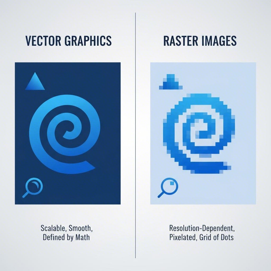
Векторни срещу растерни файлове за рязане и гравиране
Ето фундаменталната разлика, която трябва да разберете: векторните и растерните файлове имат напълно различни цели в работните процеси при лазерно рязане.
Векторни файлове се състоят от математически дефинирани пътища — линии, криви и форми, които могат да мащабират безкрайно, без да губят качеството си. Според ръководството за файловите формати на HeatSign, векторните формати са задължителни за операциите по рязане, тъй като осигуряват точността, необходима за чисти и прецизни пътища. Когато лазерният резач прочете векторна линия, той следва точно този път, за да пререже материала.
Растерни файлове са базирани на пиксели изображения — например снимки или детайлен арт. Те работят отлично за гравиране, тъй като лазерът се движи напред-назад като струйно принтиращо устройство, изгаряйки изображението в повърхността. Въпреки това, растерните изображения не могат да се използват за операции по рязане, тъй като им липсват ясно дефинираните пътища, които лазерът трябва да следва.
Ключовата разлика във вашите дизайнерски файлове:
- Линии за рязане трябва да бъдат векторни пътища с определени свойства на контура — обикновено дебелина на контура 0,1 pt в посочения цвят за рязане
- Зони за гравиране могат да бъдат запълнени векторни форми или високоразделни растерни изображения
- Векторно травиране използва векторни линии с ниска мощност, за да създаде тънки, прецизни повърхностни марки, без да прерязва материала
Много дизайнери допускат грешката да внасят изображение в JPEG или PNG формат в софтуера си за векторна графика и да предполагат, че вече е „готово за вектор“. Не е. Както Онлайн лазерна рязане Австралия обяснява, векторните файлове трябва да бъдат начертани във векторен софтуер, а не просто внесени — увеличаването на истински векторен файл показва чисти линии, докато растерните изображения стават размити.
Кога да използвате DXF вместо SVG
И двата формата, DXF и SVG, са отлични векторни формата, но се представят по-добре в различни ситуации. Изборът на правилния може да оптимизира работния процес и да предотврати проблеми при конвертиране.
DXF (Drawing Exchange Format) е предпочитаният избор за прецизни части и технически проекти. Първоначално разработен за CAD приложения, DXF файловете запазват изключителна размерна точност и работят безпроблемно с инженерен софтуер. Ако проектирате механични части, кутии с тесни допуски или нещо, което изисква точни измервания, DXF трябва да бъде вашият основен формат.
SVG (Scalable Vector Graphics) се отличава в уеб базирани работни процеси и креативни приложения. Това е отворен стандарт, поддържан от безплатен софтуер като Inkscape, което го прави достъпен за хобисти и дизайнери, които нямат скъпи CAD лицензи. SVG файловете за лазерна рязка са особено популярни за декоративни проекти, табели и дизайни, споделяни онлайн – включително много безплатни файлове за лазерна рязка, налични в дизайнерските общности.
Ето бърза справка за избор на подходящия формат:
- DXF файлове — Най-добри за прецизни части, дизайни от CAD, технически чертежи и когато размерната точност е от решаващо значение
- SVG файлове — Идеални за уеб базирани работни процеси, креативни проекти, крос-платформена съвместимост и когато се използва безплатен софтуер за дизайн
- AI (Adobe Illustrator) — Перфектни за потребителите на Adobe, поддържат сложни слоеве и обработват интригуещи дизайни с множество операции
- EPS (Encapsulated PostScript) — Гъвкав формат за професионални дизайнерски работни процеси, широко съвместим с графичен софтуер
Цветово кодиране и организация на слоевете
Файловете за лазерна рязка предават инструкции чрез цветове – и ако това не е правилно, лазерният резач няма да знае какво да реже, гравира или етикетира. Повечето софтуер за лазер използва стандартизирана цветова система, която трябва да приложите от самото начало.
Според Ръководството за производство на Харвард , трябва да използвате точни RGB цветови стойности (не CMYK), за да може лазерният Ви драйвър правилно да разпознава геометрията. Ето типичната цветова конвенция:
- Червен (RGB: 255, 0, 0) — Линии за рязане, които преминават напълно през материала
- Черен (RGB: 0, 0, 0) — Растерни области за гравиране
- Син (RGB: 0, 0, 255) — Векторно етикетиране за тънки, прецизни следи по повърхността
Организацията на слоевете е еднакво важна. Наименувайте ясно слоевете си — „Рязане“, „Гравиране“, „Траверсиране“ — и се уверете, че всички елементи на всеки слой използват правилния цвят. Честа грешка: цветът на обекта се различава от цвета на слоя, което води до неправилна обработка. Винаги проверявайте дали всяка контура съответства на предвидената операция.
Проверителен списък стъпка по стъпка за подготовката на файлове
Преди да експортирате файловете за лазерно рязане, прегледайте този процес за подготвка, за да засечете грешки, които биха могли да провалят рязането:
- Преобразувайте всички текстове в контури — Това предотвратява проблеми с подмяната на шрифтове, когато файлът се отвори на друг компютър
- Задайте дебелината на линиите за рязане на 0,1 pt — По-дебелите линии могат да бъдат интерпретирани като области за гравиране, а не като пътища за рязане
- Премахнете припокриващите се пътища — Наложените линии причиняват двойно рязане, което изгаря материала и увеличава разходите
- Уверете се, че всички пътища са затворени — Отворените пътища могат да доведат до непълни резове или непредвидимо поведение
- Разгрупирай всички обекти — Групираните елементи може да не бъдат експортирани правилно в DXF формат
- Освободи маскиращите клипове — Скритата геометрия под маските ще продължи да се обработва от лазера
- Използвай мащаб 1:1 — Проектирай в действителния размер, за да избегнеш грешки при мащабирането по време на рязане
Когато експортирате DXF файл специално, изберете версия, съвместима с вашата лазерна софтуерна платформа (често R14 или 2007 формат работят универсално). Тествайте експортирания файл, като го отворите отново, за да се уверите, че цялата геометрия е прехвърлена правилно — тази проста стъпка засича грешки при конвертиране, преди да са загубени материали.
След като проектните файлове са правилно форматирани и организирани, сте готови да се заемете със следващото важно предизвикателство: разбирането на минималните размери на елементите и допуснатите отклонения, които материалите ви всъщност могат да постигнат.
Минимални размери на елементи и спецификации за допуснати отклонения
Някога ли сте проектирали част, която изглеждаше перфектна, само за да получите изрязани с лазер части с липсващи отвори, неразбираем текст или цепки, изчезнали напълно? Не сте сами. Разбирането на минималните размери на елементите е мястото, където много средно напреднали дизайнери се затрудняват – и където правилните знания разделят функционалните части от скъпоструващи неуспехи.
Връзката между дебелината на материала и постижимия размер на елементите не е интуитивна. По-дебелите материали изискват пропорционално по-големи елементи, като всеки тип материал реагира по различен начин под лазерния лъч. Когато работите с метални листове, изрязани с лазер, правилата се различават значително от тези при рязане на фанера или акрил. Нека определим конкретните спецификации, от които се нуждаете.
Минимални диаметри на отвори според дебелина на материала
Ето един принцип, който ще ви спести безброй неуспешни резове: диаметърът на отворите никога не трябва да е по-малък от дебелината на материала и идеално трябва да е 1,5 пъти дебелината за надеждни резултати. Но това е само отправна точка — конкретните материали имат свои собствени минимални прагове, независимо от това съотношение.
Според спецификациите на материали на SendCutSend, тънки метали като 0,030" въглеродна стомана могат да постигнат минимални размери на детайлите от 0,25" x 0,375", докато по-дебелите материали изискват пропорционално по-големи минимуми. За 0,500" дебела 6061 алуминиева сплав този минимум нараства до 1" x 1".
Когато използвате рязане на ламарина по материали като неръждаема стомана, зоната с термично въздействие около всеки рез влияе на постижимото. По-малки отвори в по-дебел материал могат да доведат до прекомерна концентрация на топлина, причинявайки деформация или непълни резове. Следната таблица дава практически минимуми, базирани на реални възможности за рязане:
| Вид материал | Диапазон на дебелината | Мин. диаметър на отвор | Мин. ширина на процеп | Мин. височина на текст | Мин. разстояние |
|---|---|---|---|---|---|
| Мека стомана | 0,030" - 0,135" | 0,25" (6,35 мм) | 0.25" | 0.20" | 50% от дебелината |
| Мека стомана | 0,187" - 0,500" | 0,50" (12,7 мм) | 0.50" | 0.30" | 1x дебелината |
| неръждаема стомана 304 | 0,030" - 0,125" | 0,25" (6,35 мм) | 0.25" | 0.20" | 50% от дебелината |
| неръждаема стомана 304 | 0,187" - 0,500" | 0,50" (12,7 мм) | 0.50" | 0.30" | 1x дебелината |
| Алуминий (5052/6061) | 0,040" - 0,125" | 0,25" (6,35 мм) | 0.25" | 0.18" | 50% от дебелината |
| Алуминий (5052/6061) | 0,187" - 0,500" | 0,50" - 1,0" | 0.50" | 0.25" | 1x дебелината |
| Акрилово | 1/16" - 1/8" | 1,5x дебелината | 1,5x дебелината | 0.15" | 1x дебелината |
| Фанера | 1/8" - 1/4" | 1,5x дебелината | 2x дебелина | 0.20" | 1,5x дебелината |
| MDF | 1/8" - 1/4" | 1,5x дебелината | 1,5x дебелината | 0.18" | 1x дебелината |
Ограничения за размера на текста, който всъщност се изрязва чисто
Нищо не притеснява повече дизайнерите от прекрасната типография, която след изрязване се превръща в неразбираемо петно. Текстът по същество представлява колекция от много малки елементи — тънки линии, стеснени извивки и тясно разположение, всички те достигат до минималните граници за размер.
При лазерно изрязване на метални листове или други материали имайте предвид следните насоки за текст:
- Минимална височина на текста — 0,20" (5 мм) за повечето метали; 0,15" за тънък акрил
- Изборът на шрифт има значение — Шрифтовете без засечки с еднаква дебелина на линиите се изрязват по-чисто в сравнение с шрифтовете със засечки, които имат варираща дебелина
- Минимална дебелина на линията — Отделните линии на буквите трябва да са поне 50% от дебелината на материала
- Междубуквен интервал — Запазете поне 0,02" между знаците, за да се предотврати мостообразуване от изгаряне
Звучи ограничително? Може би — но разбирането на тези ограничения ви помага да проектирате текст, който наистина работи. Ако вашият дизайн изисква по-малък текст, помислете за векторно гравиране вместо пълно изрязване на материала.
Разбиране на допуска при лазерно рязане
Допускът при лазерно рязане определя дали вашите части ще паснат точно както е замислено или ще се нуждаят от досадна последваща обработка. Според насоките на SendCutSend, повечето материали за лазерно рязане имат допуск при рязане от ±0,005" (0,127 мм). Това означава, че всеки елемент може да се различава до 0,010" от проектните ви размери.
Какво означава това на практика? Ако проектирате отвор с размер 1,000", можете да получите отвор с размери между 0,995" и 1,005". За декоративни части тази вариация е незабележима. За прецизни сглобки това е разликата между части, които се закачат идеално, и такива, които изобщо не пасват.
Пресови съединения срещу съединения с люфт
Когато проектирате части, изрязани с лазер, които трябва да се свързват — независимо дали е ос в отвор или фланец в паз — ще избирате между два основни типа съединения:
Съединения с люфт позволяват на съединяващите се части да се плъзгат свободно един към друг без съпротивление. Отворът или пазът умишлено са по-големи от вкарвания компонент. Използвайте съединения с люфт, когато:
- Е необходимо лесно монтиране и демонтиране
- Подравняването не е критично за функцията
- Закрепващите елементи или лепилата ще фиксират връзката
Пресови съединения изискват усилие за монтиране, тъй като отворът е малко по-малък от вкарвания компонент. Триенето между повърхностите задържа частите заедно. Използвайте пресови съединения, когато:
- Искате частите да останат свързани без закрепващи елементи
- Точното подравняване е задължително
- Сглобката няма да се демонтира често
По-долу са дадени практически стойности за коригиране за всеки тип посадка, като се отчита типичната точност при лазерна рязка:
- Посадка с малък зазор — Добавете 0,005" до 0,010" към диаметъра на отвора спрямо диаметъра на вала
- Посадка с голям зазор — Добавете 0,015" до 0,020" за лесно вкарване с видим зазор
- Лека посадка с натиск — Намалете диаметъра на отвора с 0,002" до 0,005"
- Посадка с плътен натиск — Извадете 0,005" до 0,010" (изисква се инструмент за монтаж)
Правила за разстояние до ръба и между елементи
Колко близо могат елементите да бъдат до ръбовете или един до друг, преди да възникнат проблеми? Ръководните принципи за дизайн на SendCutSend препоръчват отворите да са поне 1x диаметъра им от всеки ръб, а процепите – поне 1,5x ширината им на разстояние от ръбове или други изрязани елементи.
Това не са произволни числа. Елементи, твърде близки до ръбовете, създават тънки стени, които могат да се скъсат под натоварване или да се деформират по време на рязане поради концентрация на топлина. Мостът между съседни резове – независимо дали между отвори, процепи или декоративни елементи – трябва да има достатъчна ширина, за да издържи както процеса на рязане, така и последващата употреба.
За лазерно режещи материали като цяло, използвайте тази формула за безопасно разположение на елементи:
Минимално разстояние до ръба = диаметър на елемента (или ширина) × 1,5 + дебелина на материала × 0,5
При проектиране на кутии, скоби или други конструктивни елементи, консервативното разположение осигурява пристигането на вашите части, готови за употреба, вместо да се налага преизработване. Малкото увеличение в общия размер на детайлите почти винаги си заслужава за сметка на надеждността.
Сега, когато минималните размери на елементите и допуснатите отклонения са ясно дефинирани, остава следващата ключова променлива: разбирането как изрязаният материал — материята, премахната от лазерния лъч — влияе на крайните ви размери и изисква корекции в проекта ви.
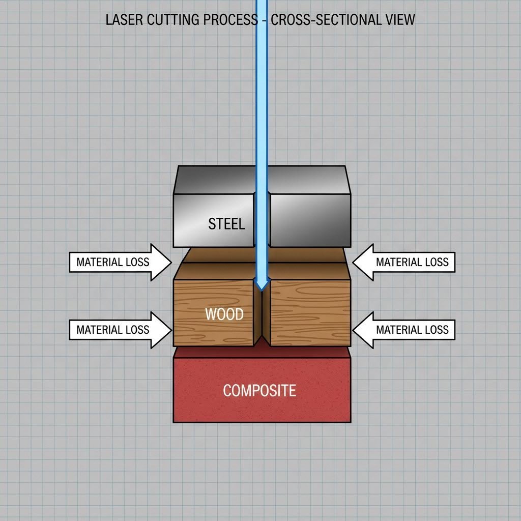
Корекции за Керф и Поведение на Материала при Проектиране
Вие сте проектирали своите части с идеални размери, сте отчели минималните размери на елементите и сте посочили тесни допуски. Но когато пристигнат изрязаните с лазер дървени или метални части, нищо не пасва точно. Дупките са леко по-големи. Езиците са твърде свободни в своите процепи. Какво се обърка?
Отговорът се крие в фактор, който много проектиращи пренебрегват: керф. Според Craft Genesis , керф е количеството материал, премахнато от лазерния лъч при рязането — обикновено около 0,005", но варира значително в зависимост от вашия материал и настройки. Ако не компенсирате тази загуба на материал в дизайна си, всяко измерване ще бъде леко неточно.
Изчисляване на керф офсета за прецизни сглобки
Ето основната концепция: когато лазерът реже по линия, той не просто разделя материала — изпарява тънка ивица от всяка страна на този път. Широчината на премахнатия материал е керфът. За 1" квадрат, който сте проектирали, действителният изрязан парче може да измерва 0,990", защото лазерът е „поел“ приблизително 0,005" от всеки ръб.
Искате ли да измерите специфичния си керф? Craft Genesis препоръчва следния прост тест:
- Изрежете квадрат 1" x 1" от вашия материал
- Измерете получения парче с цифрови шублерове
- Извадете измерената стойност от 1" (това показва общото количество премахнат материал от двете страни)
- Разделете на 2, за да намерите стойността на керф за всеки ръб
Този размер става ваш коефициент на компенсация. Когато ви е необходим отвор, който идеално да пасва на вал с диаметър 0,500", ще коригирате проекта си въз основа на това дали искате люфт или притискаща посадка – и сега знаете точно колко материал ще премахне лазерът.
Кога се прилага компенсация на ширината на реза
Тук много проектиращи се затрудняват: компенсацията на ширината на реза се прилага по различен начин за вътрешни контури (отвори, пазове) спрямо външни контури (периметри на детайли).
За външни контури — Лазерът премахва материал от външната страна на детайла, като го прави по-малък от проектния. За да компенсирате, изместете пътя на рязане навън с половината ширина на реза.
За вътрешни контури — Лазерът премахва материал от вътрешната страна на отворите и пазовете, като ги прави по-големи от проектните. За да компенсирате, изместете пътя на рязане вътрешно с половината ширина на реза.
С помощта на векторен софтуер като Inkscape или Illustrator можете да приложите тези отмествания чрез функцията за отместване на път. Както обяснява Craft Genesis, отрицателна стойност за отместване свива пътя, докато положителна стойност го разширява — изберете съответно според това дали коригирате вътрешната или външната геометрия.
Референтни стойности за материално-зависими ширини на рязане
Различните материали реагират по много различен начин на лазерната енергия, което води до различни ширини на рязане дори при идентични настройки на машината. Според анализа на xTool за рязане , металите обикновено образуват по-тесни резове (0,15 мм до 0,38 мм) в сравнение с дървото и пластмасите (0,25 мм до 0,51 мм), тъй като металите устояват на лазерната топлина без значителна загуба на материал, докато органичните материали изгарят по-лесно.
| Материал | Типична ширина на разреза | Метод за компенсация |
|---|---|---|
| Мека стомана | 0,15 мм - 0,25 мм (0,006" - 0,010") | Отместете пътищата с половин ширина на рязане; еднакво за целия лист |
| Неръждаема стомана | 0,15 мм - 0,30 мм (0,006" - 0,012") | Отместете пътищата с половин ширина на рязане; тествайте първо на отпадъчен материал |
| Алуминиеви | 0,20 мм - 0,35 мм (0,008" - 0,014") | Поместете пътя с половината широчина на реза; имайте предвид отразяващата способност |
| Акрилово | 0.25 мм - 0.40 мм (0.010" - 0.016") | Поместете пътя с половината широчина на реза; много последователни резултати |
| Фанера | 0.25 мм - 0.50 мм (0.010" - 0.020") | Тествайте всяка партида; посоката на зърното влияе на широчината на реза |
| MDF | 0.30 мм - 0.45 мм (0.012" - 0.018") | Поместете пътя с половината широчина на реза; по-последователно от фанерата |
Защо материалите се държат различно под лазера
Разбиране зАЩО вариращият рез ви помага да прогнозирате и проектирате за конкретни материали, вместо да гадаете.
Стомана и метали отвеждат топлината бързо от зоната на рязане. Тази топлопроводност означава, че лазерната енергия остава концентрирана в тесен път, което води до по-тясни резове. Въпреки това, по-дебелите метали показват леко коничен рез — както отбелязва xTool, лъчът се разширява при по-дълбоко проникване, така че резът в дъното на дебелия материал надхвърля реза на повърхността.
Акрилово реагира прекрасно на лазерно рязане. Лазерен резач за акрил стопява и изпарява материала чисто, често оставяйки полирани ръбове. Резът остава изключително постоянен по цялата плоча, което прави акрилните листове за лазерно рязане идеални за прецизни проекти. Резачът за акрил осигурява предвидими резултати серия след серия.
Фанера и дърво представляват най-голямото предизвикателство за постигане на постоянна широчина на реза. При лазерната рязка на дърво посоката на текстурата, вариациите в плътността и съдържанието на влага влияят върху количеството изгорял материал. Лазерен резач за дърво може да произведе различни ширини на реза в рамките на един и същи лист — една от причините Craft Genesis препоръчва винаги да измервате дебелината на материала с цифрова шублера преди рязане, тъй като органичните материали варират между партиди.
Формули за изчисляване на коригирани размери
Когато е необходимо плътно прилягане — например при лазерно изработени капаци от акрил или съединяващи се дървени елементи — използвайте следните формули, за да изчислите коригираните размери на проекта:
За външни размери (за получаване на правилния крайни размер на детайлите):
Коригиран размер = Желан размер + Ширина на реза
За отвори и вътрешни изрязвания (за постигане на правилен размер на отвора):
Коригиран размер = Желан размер - Ширина на реза
За съединяващи се взаимозаключващи се части:
Ширина на езика = Ширина на процепа - Ширина на реза + Желана интерференция
Имайте предвид, че скоростта на рязане влияе и на ширината на реза. По-високите скорости означават по-малко време за изгаряне на материала във всяка точка, което води до по-тесни резове. Ако машината ви позволява регулиране на скоростта, изпълнете теста за рез при планираните производствени настройки, за да получите точни стойности за компенсация.
След като вече разбирате поведението на реза и сте го отчели в своите проекти, сте готови да преминете към следващото ниво от сложност: проектиране на съединения и заключващи се връзки, които използват тези принципи за здрави и функционални конструкции.
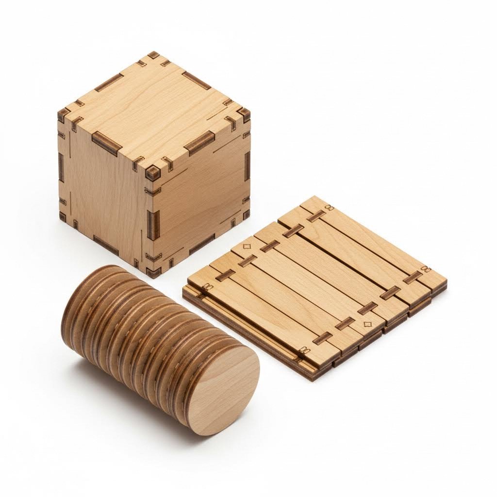
Проектиране на съединения и методи за заключващи се връзки
Вече сте овладели подготовката на файловете, разбирате минималните размери на елементите и знаете как да компенсирате реза. Сега идва вълнуващата част: проектиране на съединения, които превръщат равните листове в триизмерни структури. Независимо дали строите кутии, създавате изделия с лазерно рязане или проектирате функционални сглобки, правилният дизайн на съединенията определя дали проектът ви ще стои здраво – или ще се разпадне под натиск.
Съвместният дизайн е мястото, където проектите за лазерна рязка наистина оживяват. Добре проектирана връзка използва точността на лазерната рязка, за да създаде сглобки, които се закачат без фиксатори, огъват там, където е необходимо, или се заключват постоянно с прости механични блокировки. Нека разгледаме видовете връзки, които ще разширят вашите идеи за лазерна рязка до професионално ниво.
Разбиране на опциите за връзки
Преди да навлезем в конкретни параметри, ето общ преглед на основните видове връзки, налични за сглобки с лазерна рязка:
- Пръстови връзки (кутови връзки) — Междинно захващащи се правоъгълни езици и процепи, създаващи здрави ъглови връзки; идеални за кутии и корпуси
- Език и процеп — Прости вмъквания на езици в съответните процепи; перфектни за бързо сглобяване и подравняване
- Гъвкави шарнири — Шаблони от тънки резове, които позволяват на плосък материал да се огъва; създават гъвкави участъци без отделни компоненти
- Процепи за приковани гайки — Шестоъгълни или квадратни джобове, проектирани да задържат гайките на фиксиращите елементи; комбинира механично и хардуерно закрепване
- Закопчалки — Гъвкави езици с фиксатори, които изщракват на мястото си; позволява сглобяване и разглобяване без инструменти
Всеки тип връзка служи за различни цели в зависимост от избора на материал, натоварването и това дали сглобката трябва да бъде постоянна или демонтируема. Страхотните проекти за лазерни резачи често комбинират няколко типа връзки в един дизайн.
Параметри на пръстовите връзки за здрави сглобки
Пръстовите връзки — понякога наричани кутийни връзки — са основата на конструкцията с лазерна рязка. Според ръководството за дизайн на кутии на xTool правилното определяне на пропорциите решава дали ъглите ви ще се заключат плътно или ще люфтят
Ето ключовите параметри за успешни пръстови връзки:
- Дълбочина на езика — Трябва да съвпада точно с дебелината на Вашия материал (с корекции за широчината на рязане). Както пояснява xTool, ръбовете, проектирани твърде дълбоко спрямо дебелината, ще стърчат в ъглите, докато плитките ръбове водят до нестабилна сглобка
- Широчина на език — Обикновено добре работи стойност от 2 до 4 пъти дебелината на Вашия материал. По-тесните езици създават повече заключвания за по-голяма якост, но само до определена степен — ако са твърде тесни, те стават крехки
- Компенсация на ряз — Прилагайте половината от стойността на рязането към всяка съединяваща се повърхност. При рязане с ширина 0,010", намалете ширината на процепите с 0,005" и увеличете ширината на езиците с 0,005"
- Ъглови езици — Винаги оставяйте достатъчно материал в ъглите, за да поддържа заключващите езици; обикновено най-малко 1,5 пъти ширината на Вашия език
За лазерно изработени дървени артистични произведения и декоративни панели можете да настройвате ширината на езиците за визуален ефект, като запазвате структурната цялост. По-широки и по-редки езици създават по-смел естетически вид; по-тесни и многочисленни езици изглеждат по-прецизни
Правила за проектиране на езици и процепи
Съединенията тип шип и паз са по-прости от съединенията с пръстови зъби, но са еднакво ефективни за много идеи с лазерна рязка. Те работят особено добре за вътрешни прегради, рафтове и части, които изискват подравняване без максимална якост.
Проектни параметри за надеждни съединения тип шип и паз:
- Дължина на шипа — Минимум 2 пъти дебелината на материала; 3 пъти дебелината осигурява по-сигурно позициониране
- Зазор за паза — Добавете 0,005" до 0,010" към ширината на шипа за лесно вкарване; намалете за по-плътно прилягане
- Дебелина на шипа — Равна на дебелината на Вашия материал (шиповете се изрязват от същия лист)
- Дължина на слота — Съответства на дължината на шипа плюс 0,010" за свободно прилягане или точно съвпадение за плътно прилягане
Когато създавате арт обекти с лазерна рязка с вътрешни подпори, съединенията тип шип и паз позволяват демонтаж за транспортиране в равнина, като запазват прецизното подравняване по време на показване.
Шарнирни шаблони, които наистина огъват
Живите шарнири превръщат твърди равнинни материали в гъвкави участъци — създавайки извивки, огъвания и подвижност без отделни компоненти. Според Ръководството за живи шарнири на Sculpteo тази техника работи чрез изрязване на дълги, тънки ивици, от които всяка леко се завърта; когато съберете всички тези малки завъртания, целият материал се огъва значително.
Няколко типа шаблони осигуряват гъвкавост с различни характеристики:
- Прави успоредни резове — Най-прост шаблон; позволява огъване само в една посока
- Сerpентинни (вълновидни) шаблони — Позволяват по-драматично огъване; визуално отличаващи се
- Решетъчни шаблони — Нанасяне на кръстовидни резове, позволяващи гъвкавост в няколко посоки
- Спираловидни модели — Създава въртеливо движение в допълнение към огъването
Ключови параметри за проектиране на живи шарнири:
- Дължина на реза — Дължината на отделните елементи от модела трябва да бъде под 5 мм (0,20") за правилно завъртане при запазване на здравината
- Ширина на лентата — По-тънките ивици са по-гъвкави, но се скъсват по-лесно; започнете с тестови образци с ивици от 2–3 мм
- Повтаряне на модела — Колкото повече повторения има в зоната на огъване, толкова по-гладки са кривите
- Избор на материал — Sculpteo предупреждава, че акрилът може да се стопи, а дървото може да се запали поради концентрация на топлина; изпробвайте внимателно, преди да започнете производството
Живите шарнири работят най-добре при фанера, МДФ и някои гъвкави пластмаси. Идеални са за кутии за бижута, абажури и всеки проект, който изисква криви форми от плосък материал.
Конци за закрепени гайки и интеграция на фурнитура
Когато вашият дизайн изисква сменяеми здрави връзки или поема по-големи натоварвания от тези, които позволяват тричните съединения, конците за закрепени гайки интегрират стандартна фурнитура в лазерно изрязаните ви части.
Аспекти при проектирането на конци за закрепени гайки:
- Размери на джобовете за гайки — Конструирайте шестоъгълни или квадратни джобове с 0,010" до 0,015" по-големи от размера между равните страни на гайката
- Дълбочина на джоба — Равнява се на дебелината на гайката; проектирайте множество слоеве, ако материалът е по-тънък от гайката
- Отвор за подравняване — Включете канал, през който болтът да минава, с размер за свободно поставяне
- Дебелина на материала — Използвайте материали с дебелина поне колкото гайката за еднослойни джобове с закрепени гайки
Този метод е задължителен за кутии с панели за достъп, регулируеми сглобки и всеки проект, при който лазерно изработените конструкции трябва да взаимодействат с механични компоненти.
Сглобяване с фиксиращи елементи без инструменти
Фиксиращите елементи използват гъвкавостта на материала, за да създадат връзки, които се закачат без инструменти или здрави връзки. Те са идеални за кутии, които често се отварят, или проекти, изискващи бързо сглобяване.
Успешният дизайн на фиксиращи елементи изисква:
- Дължина на канта — По-дълги гъвкави езици по-лесно се огъват; започнете с дължина 3-4 пъти дебелината на материала
- Дълбочина на фиксация — Обикновено 0,5-1 пъти дебелината на материала; по-дълбоките фиксации държат по-здраво, но изискват по-голяма сила
- Широчина на език — По-широките езици са по-силни, но по-стифи; балансирайте според гъвкавостта на материала
- Избора на материал — Работи най-добре с гъвкави пластмаси като акрил; крехки материали могат да се счупят вместо да се огънат
Прилагане на връзките в реални проекти
Разбирането кога да използвате всеки тип връзка трансформира подхода ви към проекти с лазерен рязач:
- Кутии и корпуси — Пръстови връзки по ъглите за здравина; табли и слотове за вътрешни прегради; вградени гайки за сменяеми капаци
- Декоративни Панели — Табли и слотове за многослойни обемни ефекти; гъвкави шарнири за извити експонати
- Функционални сглобки — Скачващи съединения за достъп до панели; вградени гайки за носещи връзки; пръстови връзки за постоянни конструкции
Според проектния наръчник на Komacut, изборът на материали, които отговарят на изискванията за съединения — като се имат предвид както функционалните нужди, така и натоварванията — осигурява висококачествени резултати при управляеми разходи.
Сега, когато принципите на проектиране на съединения са част от Вашия арсенал, сте готови да създавате сложни сглобки. Но какво се случва, когато нещата не потръгнат по план? Следващата секция разглежда често срещаните проектирани грешки, които провалят проекти — и как да ги предотвратите, преди да сте изпратили файл за рязане.
Отстраняване на чести проектирани неуспехи
Следвали сте всички насоки, компенсирали сте за ширината на рязане и сте проектирали това, което би трябвало да са перфектни шаблони за лазерно рязане — а все пак детайлите ви се връщат изкривени, изгорени или изобщо без някои елементи. Дразнещо? Абсолютно. Но ето добрата новина: повечето провали се дължат на предотвратими грешки в дизайна, а не на проблеми с машината.
Разбирането защо дизайни пропадат, ви дава възможността да отстраните проблемите, преди да са загубени материал и време. Нека анализираме най-често срещаните проблеми и приложим решения от страната на дизайна, които работят при всякакви шаблони за лазерно рязане и материали.
Отстраняване на изкривяването преди то да се появи
Изкривяването е може би най-дразнещият вид повреда, защото често се появява при детайли, които в противен случай са изрязани перфектно. Според Анализа на Amber Steel , термичното рязане причинява деформации, когато се прилага твърде много топлина твърде бавно — колкото повече топлина внася процесът и колкото по-дълго тя остава, толкова по-вероятно е ръбовете да се вдигнат или повърхностите да се изместят.
Решенията от дизайнерска гледна точка за огъване се насочват към контрола върху натрупването на топлина:
- Увеличете разстоянието между резовете — Резовете, поставени твърде близо един до друг, създават локални топлинни зони. Запазете разстояние поне 2 пъти дебелината на материала между съседните линии на рез
- Избягвайте дълги непрекъснати резове — Разделете удължените прави резове на сегменти с малки мостове; това позволява охлаждане между отделните минавания
- Преразгледайте тънките участъци — Тесните материални полуострови концентрират топлина, която няма къде да се отведе; разширяване на критичните участъци или добавяне на охлаждащи фланци
- Помислете за последователността на рязане — Дизайн файлове, които насърчават рязане отвътре навън, намаляват натрупването на напрежение. Първо премахнатите вътрешни елементи позволяват рязане на външните контури без задържана топлина
Тънкостенни метали и несигурни резове са особено податливи на деформация. Както отбелязва Amber Steel, съвременните влакнести лазери с мощност 6000W до 10000W създават лъчи с диаметър само 100–150 микрона — по-тънки от човешки косъм. Тази прецизност означава, че топлината засяга само непосредствената област на реза, но само ако дизайна осигурява правилно топлинно управление.
Защо вашите малки елементи постоянно се провалят
Проектирахте деликатен модел за лазерно гравиране с изящни детайли, но получихте части с петна там, където трябва да има тънки линии? Малките елементи се провалят по предвидими причини — и разпознаването им във вашия проектен файл може да предотврати разочарование при доставката.
Чести причини за провал на малки елементи:
- Елементи под минималните размерни прагове — Прегледайте минималните спецификации за вашия материал; отвори, по-малки от дебелината на материала, и текст с височина под 0,15" вероятно ще се провалят
- Недостатъчна ширина на мостовете — Материалът, свързващ малките острови с основната част, трябва да е достатъчно широк, за да издържи рязането. Използвайте мостове с ширина поне 0,020" за метали и 0,030" за дърво
- Натрупване на топлина при стеснена геометрия — Няколко реза, сходящи се в малки области, създават излишък от топлина, която разтопява или изгаря деликатни елементи
- Вътрешни ъгли с по-малки размери от зададените — Остри вътрешни ъгли от 90 градуса концентрират напрежението и често се пукат или изгарят; добавете отвори за облекчаване в ъглите
Идентифициране на проблемна геометрия преди рязане
Звучи сложно? Ето систематичен подход за преглед на вашите лазерни шаблони за потенциални повреди, преди да изпратите файловете в производство:
- Увеличете до мащаб 1:1 — Вижте дизайна си в действителен размер; елементи, които изглеждат уместни при увеличение, може да се окажат невъзможно малки в истинския мащаб
- Проверете минималните ширини — Използвайте измервателния инструмент на софтуера си, за да проверите дали всички мостове, фланци и свързващи елементи отговарят на минималните спецификации
- Проверка на последователността на разстоянията — Проследете области, където рязането се съсредоточава или групира; тези зони стават точки на концентрация на топлина
- Тествайте вътрешните ъгли — Идентифицирайте всички остри вътрешни ъгли и проверете дали са направени компенсационни резове в необходимите места
- Симулирайте влиянието от подреждането — Ако частите ви бъдат плътно подредени, имайте предвид как могат да се припокриват топлинните зони на съседните части
Стратегии за подреждане, които предотвратяват натрупване на топлина
Начинът, по който подреждате частите на лист материял, е толкова важен, колкото и самите части. Според Amber Steel, умният софтуер за подреждане играе значителна роля за намаляване на натрупването на топлина – подреждането на частите по начин, който намалява движението на рязещия факел и избягва натрупване на топлина, помага за запазване на стабилността на материала и общата му равнинност.
Съображения за проектиране относно подреждането:
- Запазване на минимално разстояние — Задръжте детайлите поне на разстояние 1x дебелина на материала; 2x дебелина за чувствителни към топлина материали като алуминий
- Избягвайте линейни подредби — Детайлите, подредени в редици, създават непрекъснати топлинни пътища; стъпаловидното подреждане позволява охлаждане между рязанията
- Редувайте зоните за рязане — Проектирайте компоновки, при които лазерът преминава по цялата ламарина, вместо да се концентрира в една област
- Внимателно преценявайте споделените ръбове — Въпреки че споделените резове спестяват материал, те могат да създадат концентрации на напрежение; оценете дали спестяванията оправдават риска
Техники за отпускане на напрежението във вътрешни ъгли
Остри вътрешни ъгли създават области с повишено напрежение, които могат да се напукат, изгорят или разкъсат по време и след рязане. Според указанията на SendCutSend, премахването на малко количество материал в точките на напрежение предотвратява нежелани разкъсвания и деформации.
Приложете тези методи за отпускане на ъглите към вашите шаблони за гравиране с лазер и режещи дизайни:
- Отпускане с формата на кост — Малки кръгли изрязвания във вътрешните ъгли позволяват на режещите инструменти напълно да достигнат до ъгъла, като едновременно разпределят напрежението
- Т-образно отпускане — Удължени резове, перпендикулярни на ъгъла, осигуряват подобно разпределяне на напрежението, но с различен визуален ефект
- Закръглени ъгли — Заменете остри вътрешни ъгли от 90 градуса с малки радиуси (минимум 0,020", за повечето материали)
- Размери на отпускането — Ширината на отпускането трябва да бъде поне половината от дебелината на материала; дълбочината трябва да преминава зад пресичането на ъгъла
Когато материалът се огъва или подлага на натоварване, част от него се разтяга, докато друга част се компресира. Ако не сте предвидили място, където това напрежение да се разпредели, то ще си намери собствено пространство — което води до нежелани деформации или скъсвания.
Бърз справочник за чести грешки в дизайна
Използвайте този контролен списък, за да идентифицирате и отстраните проблеми, преди да достигнат лазера:
- Непълни резове поради недостатъчно разстояние — Увеличете разстоянието между резовете до поне 2 пъти дебелината на материала
- Горещинни следи от плътно подреждане — Добавете разстояние между детайлите; изместете подредбата, за да разпределите топлината
- Деформация от натрупване на топлина — Разделете дългите резове на сегменти; проектирайте последователност на рязане отвътре навън
- Губене на детайли поради твърде малки елементи — Проверете дали всички елементи отговарят на минималните размерни изисквания; увеличете или премахнете проблемните елементи
- Изпадане на част по време на рязане — Добавете фиксиращи табове или мостове; проверете дали ширината на мостовете надхвърля минималните стойности
- Напукани вътрешни ъгли — Приложете „dog-bone“, „T-bone“ или закръглено ослабване към всички остри вътрешни ъгли
Следването на тези насоки за рязане превръща подхода ви към отстраняване на неизправности от реактивен в превентивен. Като идентифицирате проблемна геометрия в проектните си файлове преди рязане, елиминирате разочарованието и разходите от повредени части.
Сега, когато разполагате с методи за отстраняване на неизправности, следващата стъпка е изборът на подходящ софтуер, за да прилагате тези проектирани принципи ефективно и точно.
Сравнение на софтуер за проектиране при работни процеси за лазерно рязане
Вие сте овладели файловите формати, минималните функции, компенсацията на широчината на рязане, дизайна на съединенията и отстраняването на неизправности, но цялата тази информация няма значение без подходящия софтуер, който да оживи вашите проекти. Изборът на софтуер за дизайн при лазерно рязане не е просто въпрос на лични предпочитания; той директно влияе на ефективността на вашия работен процес, възможностите за проектиране и в крайна сметка – на качеството на готовите детайли.
Пейзажът от софтуер за лазерно гравиране и режещи инструменти варира от безплатни opensource решения до професионални абонаменти, които струват стотици долари годишно. Кой от тях отговаря на вашите нужди? Това зависи от това какво строите, колко сложни са вашите проекти и колко време сте готови да отделите за учене. Нека анализираме вариантите ви с конкретни препоръки.
Компромиси между безплатен и платен софтуер
Преди да преминете към конкретни програми, разберете основните компромиси, които правите при избора между безплатни и платени решения.
Според Ръководството на Thunder Laser USA за софтуера безплатни инструменти като LaserGRBL и Inkscape предлагат достатъчно възможности за учене и прости проекти, но повечето бизнеси в крайна сметка преминават към платени решения за по-напреднали функции и спестяване на време.
Предимства на безплатен софтуер:
- Липса на финансов бариера за влизане — идеално за начинаещи, които изучават лазерното рязане
- Отворени проекти като Inkscape имат големи общности, които предоставят уроци и добавки
- Достатъчно за прости проекти, декоративни резове и усвояване на основите
Ограничения на безплатния софтуер:
- По-малко функции за автоматизация означава повече ръчна работа за всеки проект
- Ограничена поддръжка на файлови формати може да изисква заобикални методи за конвертиране
- По-слаба поддръжка при възникване на проблеми
- Може да няма директна интеграция за управление на машината
Предимства на платения софтуер:
- Разширени функции като параметрично проектиране, симулации и пакетна обработка
- Директният контрол върху машината елиминира необходимостта от смяна на софтуера
- Профессионална поддръжка и редовни актуализации
- По-добра ефективност в работния процес спестява време при сложни проекти
За бизнеса платеният софтуер често се изплаща сам, като намалява грешките и спестява часове ръчна работа. За любителите, които правят проекти от време на време, безплатните инструменти могат да бъдат достатъчни за неопределено време.
Таблица за сравнение на софтуера
По-долу е дадено задълбочено сравнение на най-популярните опции за софтуер за лазерно гравиране, подредени по възможности и сфери на приложение:
| Име на софтуера | Ценова позиция | Най-добър за | Обучаемост | Формати за експорт |
|---|---|---|---|---|
| Inkscape | Безплатен (с отворен код) | Дизайнерите с ограничен бюджет; работни потоци въз основа на SVG; начинаещи, които учат векторен дизайн | Умерена | SVG, DXF, PDF, EPS, PNG |
| Adobe Illustrator | $22,99/месец (абонамент) | Професионални дизайнери; сложни художествени проекти; интеграция с екосистемата на Adobe | Умерена до стръмна | AI, SVG, DXF, PDF, EPS |
| CorelDRAW | $249/годишно или $549 перпетуална лиценз | Изработващи табели; професионална графика; потребители, желаещи опция за перпетуален лиценз | Умерена | CDR, SVG, DXF, AI, PDF |
| Fusion 360 | Безплатно (лично) / 545 USD/годишно (търговско) | Инженери; параметрични проекти; 3D модели, изискващи равни шаблони; прецизни части | Стръмна | DXF, DWG, STEP, IGES |
| LightBurn | 60 USD еднократно (G-code) / 120 USD (DSP) | Цялостно проектиране и контрол на машини; сериозни любители; малки фирми | Лесно до умерено | SVG, DXF, AI, родни формати |
| LaserGRBL | Безплатен (с отворен код) | GRBL-базирани диодни лазери; начинаещи; прости гравировъчни проекти | Лесно | G-код, SVG, изображения |
Разбиране на разликите в работните потоци
Изборът на софтуер оформя целия ви процес от дизайн до рязане. Две различни категории обслужват различни нужди:
софтуер за 2D илюстрации (Inkscape, Illustrator, CorelDRAW)
Тези програми се отличават с възможностите си за създаване и редактиране на векторни изображения. Рисувате форми, криви и текст директно – идеално за декоративни дизайни, табели и художествени проекти. Според Tuofa Machining, Adobe Illustrator предлага обширни инструменти за редактиране на вектори, което го прави отлично решение за сложни дизайни, изискващи детайлна графика.
Все пак, софтуерът за илюстрации обикновено изисква отделна програма за управление на лазера. Ще експортирате файлове (обикновено DXF или SVG) и след това ще ги импортирате в софтуер за управление на машината, като LightBurn или контролера, доставен заедно с вашия лазер.
CAD програми (Fusion 360)
CAD софтуерът подхожда към дизайна от инженерна гледна точка. Дефинирате части, използвайки прецизни размери, ограничения и математически зависимости. Промените се прилагат автоматично — промените ли един размер, свързаните елементи се актуализират съответно.
Този параметричен подход е безценен при проектирането на механични части, корпуси с конкретни хардуерни изисквания или всеки проект, при който размерите трябва да са математически свързани помежду си.
Интегриран софтуер за управление (LightBurn, LaserGRBL)
Тези програми обединяват възможности за дизайн с директно управление на машината. Създавате или импортирате дизайни, задавате параметри за рязане (скорост, мощност, брой проходи) и изпращате задачите директно към лазера — всичко това без превключване между приложения.
Както отбелязва 1Laser, софтуерът LightBurn постига баланс между потребителски приятелски интерфейси и напреднали функции, което го прави подходящ както за начинаещи, така и за професионалисти. Ако разглеждате възможността за изтегляне на lightburn, имайте предвид, че се предлага 30-дневен безплатен пробен период, за да изпробвате функциите, преди да закупите.
Избор на софтуер според сложността на проекта
Типът на вашия проект трябва да определи избора на софтуер. Ето как да съотнесете инструментите със задачите:
Прости декоративни проекти
За основни табели, украшения и художествени резки започнете с Inkscape или LaserGRBL. Тези безплатни опции се справят с прости векторни работи, без да ви задушават с функции, които няма да използвате. LaserGRBL работи особено добре за потребителите на диодни лазери, управляващи машини, базирани на GRBL.
Производствени графики и табели
Когато клиентите очакват професионални крайни продукти, а вие редовно създавате различни дизайни, Adobe Illustrator или CorelDRAW оправдават своята цена. Обширните библиотеки с инструменти, контрола върху типографиката и опциите за професионален изход улесняват търговската дейност.
Презиционни механични части
Капаци, скоби, сглобки с конкретни допуски – тези елементи изискват параметричните възможности на Fusion 360. Според Tuofa Machining, Fusion 360 е мощен избор за хора, които създават сложни 3D модели и генерират траектории на инструменти, подходящ както за процеси на проектиране, така и за производство.
Защо параметричното проектиране е важно: представете си, че проектирате кутия за електроника. Указвате, че монтажните отвори да са на 5 мм от ръбовете, а общият размер да побира определени компоненти. По-късно ви трябва по-голяма версия за различна електроника. В параметричен софтуер променяте размерите на компонентите и всичко — позиции на отвори, общ размер, шаблони за вентилация — се преизчислява автоматично. В илюстративен софтуер ще трябва да начертаете всичко ръчно отново.
Цялостен работен процес
За потребителите, които искат проектиране и управление на машината в един пакет, софтуерът LightBurn предлага най-добрия баланс. Той осъществява векторно редактиране, проследяване на изображения, настройки за мощност/скорост и директна връзка с машината. Както отбелязва Thunder Laser USA, LightBurn работи на Windows, Mac и Linux, поддържа стотици марки лазерни машини и изисква еднократно плащане вместо постоянен абонамент.
Някои собственици на машини xTool може да разглеждат xtool софтуер (xTool Creative Space), който предлага потребителско приятелски опит, специално разработен за продуктите на xTool. Въпреки това, 1Laser предупреждава че простотата му може да бъде ограничаваща за напреднали потребители, като липсват някои възможности за персонализация, присъстващи в по-гъвкавите решения.
Епрепоръки според ниво на опит
Начинаещи: Започнете с Inkscape за основите на дизайна и LaserGRBL, ако използвате диоден лазер. Тази безплатна комбинация учи на основните принципи, без финансови рискове. Преминете към LightBurn, когато сте готови за интегриран контрол и по-бързи работни процеси.
Средно напреднали потребители: LightBurn софтуерът покрива повечето нужди – дизайн, редактиране и рязане от един интерфейс. Добавете Fusion 360 (безплатен за лично ползване), когато проектите изискват параметрична точност или проектирате части, които трябва да се съединяват с конкретни допуски.
Професионалисти: Комбинирайте Adobe Illustrator или CorelDRAW за дизайнерски проекти пред клиенти с LightBurn за производство. Помислете за Fusion 360 при инженерни проекти. Инвестицията в няколко специализирани инструмента се отплаща чрез по-висока ефективност и възможности.
След като сте избрали и настроили софтуера, сте готови да преминете от дизайн към производство – превръщайки внимателно подготвените файлове във физически части чрез производствен поток, проектиран за последователност и качество.
Дизайн за производство и производствен поток
Вие сте създали безупречен проектен файл – с правилни формати, приложена компенсация на реза, точно размерени връзки. Но все още съществува съществена пропаст между завършения ви дизайн и успешна производствена серия. Разбирането на процеса на лазерна рязка от подаване на файла до готовата детайл осигурява, че внимателно подготвената от вас работа ще се превърне във физически компоненти, отговарящи на спецификациите всеки път.
Тук се съчетават познанията за дизайн с производственото изпълнение. Независимо дали режете един прототип или увеличавате мащаба до хиляди части чрез лазерно рязане, принципите на дизайна за възможност за производство (DFM) определят ефективността, последователността и разходите. Нека преодолеем тази последна пропаст.
От файл с дизайн до готова за производство част
Пътуването от вашия файл за лазерно рязане до физическа част включва няколко етапа, на които малки пропуски могат да станат скъпоструващи проблеми. Разбирането на този работен процес ви помага да предвидите изискванията и да подготвите файлове, които минават гладко през производството без закъснения.
Етап 1: Валидиране на файла
Когато вашият файл пристигне в услуга за рязане или достигне до собствената ви машина, той подлежи на валидиране. Според насоките за дизайн на SendCutSend, често срещаните проблеми, засечени на този етап, включват неkonвертирани текстови полета, отворени контури и проблеми с проверката на размерите — особено при файлове, конвертирани от растерни формати.
Какво се случва по време на валидирането:
- Проверките за непрекъснатост на траекторията гарантират, че всички изрязани линии образуват затворени форми
- Проверка на цветовата кодировка потвърждава, че операциите са правилно определени
- Дименсионен анализ улавя грешки при мащабиране, преди материалът да е загубен
- Прегледът на размера на характеристиката идентифицира елементи под минималните прагове
Етап 2: Възстановяване на гнездата и оптимизиране на материала
Индивидуалните ви конструкции на детайли се подреждат върху листов материал, за да се максимизира добивът и да се минимизира отпадъкът. Както обяснява Baillie Fab, лазерният резач изисква периферна граница до 0,5" около всеки детайл — което означава, че два детайла с размери 4'x4' всъщност няма да поберат на лист с размери 4'x8', както може би очаквате. Проектирането на детайли с оглед на стандартните размери на листовия материал директно влияе върху вашите разходи.
Етап 3: Задаване на параметри
Въз основа на Вашата спецификация за материала, операторът задава параметрите на рязане — мощност на лазера, скорост, вид на помощния газ и позиция на фокуса. При метали изборът между кислород и азот като помощен газ влияе върху качеството на ръба: кислородът допринася за по-високи температури при дебелостенна въглеродна стомана, докато азотът осигурява гладки, без оксиди ръбове при неръждаема стомана и алуминий.
Етап 4: Рязане и проверка на качеството
Фактическото рязане се извършва бързо — често това е най-краткият етап от целия процес. Проверката след рязане потвърждава размерната точност, качеството на ръба и целостта на елементите. Детайлите, които не издържат проверката, по-често се дължат на проектирани грешки, отколкото на проблеми с машината.
Принципи за проектиране, специфични за лазерно рязане
Проектирането с оглед производството не е просто въпрос на изработка на детайли, които може могат да бъдат изрязани — става дума за проектиране на детайли, които се режат ефективно, последователно и икономично. Тези принципи отличават любителските проекти от файловете, готови за производство.
Истински дъги срещу сегментирани криви
Дали вашият CAD програм чертае криви с плоски сегменти вместо сплошни дъги? Според Baillie Fab , по-дългите сегменти могат да бъдат интерпретирани като фасети вместо непрекъснати криви – представете си, че искате окръжност, но получавате шестоъгълник. Преди да изпратите файловете, проверете дали извитите линии са начертани с истински дъги.
Свързана геометрия
Всеки контур трябва да образува пълен, затворен път. Несвързани линии или отворени контури водят до зле изрязани части или изискват допълнително проектиране, което забавя проекта ви. Използвайте инструментите за анализ на пътеки в софтуера си, за да идентифицирате и поправите празнините преди експортиране.
Правила за разстояние между отвори и ръбове
Отворите, разположени твърде близо до ръбовете на материала, създават крехки участъци, склонни към разкъсване. Както отбелязва Baillie Fab, поддържайте разстояние, равно поне на дебелината на материала, между отворите и ръбовете – за някои материали като алуминия е необходимо разстояние от 2 пъти дебелината или повече.
Посочване на посоката на зърното
За матови метали или материали с посочени свойства, посочете коя страна е „предна“ и укажете посоката на структурата на чертежа. Повечето метални листове са с размери 4'x10' с надлъжна структура – ориентирането на детайлите по тази структура осигурява максимален добив и последователен външен вид.
Вашият предварителен контролен списък
Преди да изпратите шаблони за лазерно рязане или производствени файлове, проверете всеки елемент от този контролен списък:
- Всички контури са затворени — Няма отворени контури или несвързани крайни точки; изпълнете проверка на контурите в софтуера си
- Правилно зададени цветове на слоевете — Линии за рязане в определения цвят за рязане (обикновено червен RGB 255,0,0); зоните за гравиране правилно запълнени
- Експортиран подходящ файлов формат — DXF за прецизни части; SVG за уеб базирани работни потоци; проверете съвместимостта с вашия доставчик
- Текстът е конвертиран в контури — Няма активни текстови полета, които биха могли да причинят проблеми с подмяната на шрифтове
- Премахнати застъпващи се пътища — Използвайте функции за свързване или обединяване, за да премахнете дублирани линии, които причиняват двойно рязане
- Включени са толерантни означения — Посочени са критични размери; посочени са изисквания за прилягане за съчленяващи се части
- Посочен е материалът и дебелината — Ясна документация за предвидения материал предотвратява скъпи предположения
- Указано е направлението на зърното — За насочени материали посочете коя страна е отгоре и ориентацията на зърното
- Мащабът е проверен в отношение 1:1 — Отпечатайте своя дизайн в мащаб 100%, за да потвърдите физически размерите, преди рязане
Работа с производствени партньори за най-добри резултати
За сложни проекти — особено прецизни метални компоненти за автомобилна, строителна или механична употреба — работата с производители, предлагатши комплексна DFM поддръжка, трансформира вашия производствен процес. Правилният партньор засича проблеми в дизайна, преди да започне рязането, и предлага оптимизации, които може би няма да сте имали предвид.
Какво да търсите при производствен партньор:
- Услуги за DFM преглед — Инженери, които анализират вашите проекти и препоръчват подобрения преди производството
- Бързо предоставяне на оферти — Бързо обратно връзка позволява бърза итерация; закъснения тук забавят целия ви проектен график
- Капацитетите им за прототипиране — Възможност за бързо производство на малки количества за валидиране, преди да се ангажирате с големи обеми
- Сертификати за качество — Стандарти като IATF 16949 показват последователни, документирани производствени процеси
- Експертност в материалите — Партньори с опит в работата с конкретните материали могат да Ви посъветват за проектни аспекти, които бихте пропуснали
За автомобилни и структурни метални приложения, изискващи прецизност над стандартното лазерно рязане, производителите, специализирани в метален штампинг и сглобки, предлагат допълнителна стойност. Компании като Shaoyi Metal Technology съчетават възможности за бързо прототипиране — често със срок от 5 дни — с автоматизирано масово производство и предлагат подкрепа при проектирането (DFM), която открива проблеми в конструкцията още в началото. Техният 12-часов срок за оферти осигурява бързо итериране, което е от съществено значение за валидиране на лазерно рязане преди серийно производство.
Ключов е изборът на партньори, които разглеждат Вашия проект за лазерно рязане като сътрудничество, а не просто като транзакция. Когато производителите отделят време да преглеждат вашите проекти и предлагат подобрения, те Ви помагат да избегнете скъпоструващи грешки, като едновременно подобряват качеството на детайлите.
Мащабиране от прототип до производство
Първият успешен разрез потвърждава конструкцията — но мащабирането към производство внася нови аспекти:
Съгласуване на партидите
Единичните прототипи позволяват ръчна проверка, но серийното производство изисква вградена последователност. Уверете се, че файловете ви посочват точни параметри, а не разчитат на интерпретацията от оператора. Документирайте източниците на материала, параметрите на рязане и критериите за качество.
Оптимизация на разходите
Според Baillie Fab истинската стойност на лазерното рязане се постига при производство в по-големи обеми. Ако имате нужда само от няколко части, по-прости процеси могат да са по-икономични. Обсъдете обемните прекъсвания с производствения си партньор, за да разберете кога лазерното рязане става оптимален избор.
Вторични операции
Много части, произведени чрез лазерно рязане, изискват допълнителна обработка — огъване, заваряване, довършване или сглобяване. Проектирайте с оглед на тези последващи операции. Добавяйте отвори за релеф при огъване. Включвайте елементи за подравняване при заварявани сглобки. Помислете как ще се държат и фиксират частите по време на вторични операции.
Сега, когато работният ви процес от дизайн до производство е завършен, сте преодолели пропастта между дигиталната креативност и реалното производство. Последната стъпка? Обединяване на всичко научено в ресурси за бързо справяне, които правят тези принципи лесно достъпни всеки път, когато започнете следващия си проект.
Основни правила за дизайн и следващи стъпки
Преходихте през файлови формати, минимални елементи, компенсация на рязане, проектиране на съединения, отстраняване на неизправности и избор на софтуер. Това е голям обхват — и много детайли за запомняне, когато гледате празна дизайнерска хартия. Тази последна секция обобщава всичко в практически справочни материали, към които можете да се връщате преди всеки проект.
Представете си какво следва като защитна мрежа за вашия лазерен дизайн. Когато сте дълбоко в сложен проект и се чудите дали тази дупка с диаметър 0,15" ще бъде изрязана чисто в стомана с дебелина 1/8", ще имате отговорите набързо. Тези обобщени принципи превръщат придобитото знание в практически инструменти за постоянен успех.
Вашият контролен списък за предварително изрязване
Преди да изпратите всеки файл за производство, преминете през този задълбочен процес на проверка. Според Ръководството за дизайн на Impact Fab контролните списъци са от съществено значение, за да се гарантира, че проектът ви ще бъде реализиран точно както е предвидено — най-важно е консултирането с вашия производител, но този списък ви осигурява успех.
Златното правило за дизайна при лазерно рязане: измервай два пъти, проверявай три пъти, режи веднъж. Всеки отделен минут, прекаран в проверка на файла ви за дизайн, спестява часове работа и загуба на материал.
Проверка на подготовката на файла:
- Дизайнът е във векторен формат и мащабиран в правилен размер (мащаб 1:1)
- Всички текстове са преобразувани в контури — няма останали активни текстови полета
- Линиите за рязане са зададени с дебелина на щриха 0,1 pt и правилно RGB кодиране на цветовете
- Всички пътища са затворени, без отворени крайни точки или прекъсвания
- Припокриващите се пътища са премахнати чрез функции за сливане или обединяване
- Маските за отсичане са освободени, а групираните обекти — разгрупирани
- Файлът е експортиран в подходящ формат (DXF за прецизност, SVG за уеб работни потоци)
Проверки на геометрията и елементите:
- Диаметрите на отворите са равни или по-големи от минималната дебелина на материала
- Височината на текста над 0,15" за гравиране и 0,20" за изрязване напълно
- Ширината на мостовете между елементи е поне 2 пъти дебелината на материала
- Вътрешните ъгли включват релефни резове (шаблон тип „кучешка кост“, „Т-образна кост“ или с радиус)
- Разстоянието от краищата до отворите е поне 1,5 пъти диаметъра на отвора
Материал и производствени спецификации:
- Видът и дебелината на материала са ясно документирани
- Компенсацията за рязане е приложена правилно към вътрешни и външни контури
- Посоката на зърното е посочена за материалите с определена насока
- Изискванията за допуснати отклонения са обозначени за критичните размери
- Създаден е резервен файл преди окончателното експортиране
Бързо справочно ръководство за дизайн, специфичен за материала
Дизайнът за лазерно рязане изисква адаптиране на подхода спрямо уникалното поведение на всеки материал. Философията „материалът първо“, описана в това ръководство, се основава на разбирането, че стомана, акрил и фанера изискват различни проектни решения — още преди да начертаете първата линия.
Използвайте тази справочна таблица при стартиране на всеки проект. Тя обобщава основните правила, които предотвратяват най-честите неуспехи:
| Дизайн елемент | Правило | Защо има значение |
|---|---|---|
| Минимално разстояние | Поддържайте поне 2 пъти дебелината на материала между съседни резове | Предотвратява натрупването на топлина, което причинява деформации и изгаряния |
| Минимален диаметър на отвора | Диаметърът на отвора трябва да бъде равен или по-голям от дебелината на материала (1,5 пъти за дърво/акрил) | Малки отвори концентрират топлина и може да не се изрязват чисто или изобщо |
| Минимална височина на текста | 0,20" за метали; 0,15" за тънък акрил; използвайте шрифтове без засечки | Малките текстови елементи се сливат или изгарят по време на рязане |
| Компенсация на ряз | Преместете външните контури навън, вътрешните контури навътре с половин ширина на реза | Конструкциите без компенсация произвеждат части, които не съответстват на предвидените размери |
| Вътрешни ъгли | Добавете релефни резове или минимален радиус от 0,020" към всички остри вътрешни ъгли | Остри ъгли създават концентрации на напрежение, които причиняват пукнатини или разкъсване |
| Разстояние до ръба | Запазете разстоянието от особеностите до ръба на детайла поне 1,5 пъти диаметъра им | Тънките стени между особености и ръбове са крехки и може да се скъсат |
| Ширина на моста | Минимум 0,020" за метали, 0,030" за дърво между свързани елементи | Тесните мостове изгарят по време на рязане, което води до изтриване на части |
| Формат на файла | DXF за прецизни части; SVG за уеб работни потоци; проверете настройките за експорт | Грешен формат или версия причинява грешки при конвертиране и загуба на геометрия |
| Затваряне на контур | Всички режещи контури трябва да образуват пълни, затворени пътища без прекъсвания | Отворените пътища причиняват непълни резове или непредвидимо поведение на лазера |
| Да комбинирате цветове | Използвайте точни RGB стойности (Червен 255,0,0 за рязане; Черен 0,0,0 за гравиране) | Неправилните цветове водят до назначаването на грешни параметри за операциите |
Мислене, насочено първо към материала
Всеки успешен лазерен дизайн започва с един прост въпрос: какво режа? Вашият отговор оформя всяко следващо решение.
Стоманата провежда топлина бързо — проектирайте с по-малки разстояния. Акрилът се стапя чисто — очаквайте постоянна дебелина на реза. Файната дъска варира според текстурата — тествайте всяка партида. Материалът диктува правилата; вашата задача е да ги спазвате.
Този подход, при който първо се взема предвид материала, отличава лазерните режещи проекти, които работят, от тези, които се провалят. Когато разберете зАЩО че файната дъска изисква по-големи допуски за процепи в сравнение с акрила, или зАЩО че алуминият изисква по-голямо разстояние до ръба в сравнение със стоманата, преставате да запаметявате произволни правила и започвате да вземате обосновани решения.
Според ръководството за дизайн на Komacut използването на стандартни дебелини на материала е един от най-лесните начини за оптимизиране на процеса на лазерно рязане – тези материали са по-икономични, лесно достъпни и лазерът ви вече е калибриран за тях. Необичайните дебелини изискват специално набавяне и калибриране, което увеличава както времето за изработка, така и разходите.
От дизайн до производство: Следващите ви стъпки
Сега притежавате знанието да създавате шаблони, готови за лазерно рязане, които се режат успешно още при първия опит. Но самото знание не произвежда детайли — действието прави това. Ето как да продължите нататък:
За лични проекти:
Започнете с прости дизайни, които проверяват вашето разбиране. Изрежете няколко пробни парчета от избрания материал, за да проверите стойностите на реза (kerf) и минималните работни характеристики на елементите, преди да започнете сложни проекти. Използвайте безплатните софтуерни опции (Inkscape, LaserGRBL), за да развивате уменията си без финансов натиск.
За професионални приложения:
Комплексните проекти — особено прецизни метални компоненти за автомобилна, строителна или механична употреба — извличат огромна полза от професионална подкрепа при проектирането за производство (DFM). Според Impact Fab, сътрудничеството с производител, който отделя време да обсъди детайли по Вашия проект, помага да се избегнат многобройните възможни негативни последици, които идват от оставянето на неща на случайността.
За проектиране за лазерна рязка, изискващи потвърдена прецизност, партньорството с производители, предлагателни всеобхватен DFM преглед, позволява засичането на проблеми преди те да се превърнат в скъпоструващи грешки. Компании като Shaoyi Metal Technology предлагат бързо итериране, което е задължително за уверено придвижване от дизайн до прототип — тяхната възможност за предоставяне на оферта за 12 часа и изработка на прототип за 5 дни осигурява бързи цикли на валидиране, благодарение на които проектите се реализират по график.
За непрекъснато подобрение:
Водете дневник с дизайн, в който отбелязвате какво работи и какво не. Записвайте стойностите на ширината на реза за различните материали, минималните елементи, които са успешно изрязани, и параметрите на фугите, които осигуряват плътно сглобяване. Този персонализиран справочник ще бъде незаменим, докато се заемате с все по-сложни лазерни проекти.
Окончателни мисли
Успешното лазерно рязане започва задълго преди лъчът да докосне материала. То започва с разбирането, че всяко проектно решение — от избора на файлов формат до размерите на елементите и компенсацията на ширината на реза — директно влияе на това дали вашите части ще бъдат готови за употреба или ще се наложи досадно преработване.
Принципите в това ръководство отразяват хиляди общо натрупани часове опит, грешки и прецизност. Прилагайте ги последователно, проверявайте работата си спрямо предоставените контролни списъци и подходете всеки проект с мислене, насочено първо към материала, което отличава любителските опити от професионалните резултати.
Следващият ви дизайн ви очаква. Направете го досега най-добрия.
Често задавани въпроси относно дизайна за лазерно рязане
1. Къде мога да намеря безплатни проекти за лазерна рязка?
Няколко авторитетни уебсайта предлагат безплатни файлове за лазерно изрязване, включително Atomm, 3axis.co, Vecteezy, Ponoko, Design Bundles, Thingiverse и Instructables. Тези платформи предоставят SVG, DXF и други векторни формати, готови за рязане. При използването на безплатни файлове винаги проверявайте затварянето на контурите, проверете за правилно оцветяване и се уверете, че размерите съответстват на дебелината на вашия материал, преди да започнете рязката. Много файлове изискват корекции за компенсация на ширината на реза (kerf), за да се постигнат прецизни сглобки.
2. Какво софтуер е най-добър за проекти за лазерна рязка?
Най-добрият софтуер зависи от сложността на проекта и бюджета. За начинаещи Inkscape (безплатен) в комбинация с LaserGRBL работи добре за прости проекти. LightBurn (единовремено плащане 60–120 долара) предлага отличен баланс между дизайн и контрол на машината за сериозни любители. Adobe Illustrator се отличава при сложни художествени проекти, докато Fusion 360 осигурява параметрични възможности за прецизни механични части. Изборът зависи дали са ви необходими инструменти за 2D илюстрации или CAD точност за инженерни задачи.
3. Кой файлов формат трябва да използвам за лазерно рязане?
DXF е предпочитаният формат за прецизни части и дизайни от CAD поради изключителната си размерна точност. SVG работи най-добре за уеб базирани процеси, творчески проекти и когато се използва безплатен софтуер като Inkscape. AI файловете са подходящи за потребителите в екосистемата на Adobe, които работят със сложни слоеве. Независимо от формата, уверете се, че всички контури са затворени, щриховете са зададени на 0,1 pt, текстът е конвертиран в контури и е приложено правилно RGB кодиране на цветовете за операциите рязане и гравиране.
4. Как да компенсирам лазерния разрез в моите проекти?
Компенсацията на лазерния разрез изисква отместване на рязането според ширината на премахнатия материал. За външни контури отместете пътя навън с половината ширина на разреза, за да запазите правилния размер на детайла. За вътрешни контури (отвори и процепи) отместете навътре с половината ширина на разреза. Типичните стойности за разрез варират от 0,15–0,25 мм за метали до 0,25–0,50 мм за дърво и акрил. Винаги правете пробно рязане върху вашия конкретен материал, за да измерите реалния разрез преди производството.
5. Какви са минималните размери на елементите при лазерно рязане?
Минималните размери на елементите зависят от типа и дебелината на материала. За метали диаметърът на отворите трябва да бъде поне 0,25 инча за тънки материали (под 0,135 инча) и 0,50 инча за по-дебели материали. Минималната височина на текста е 0,20 инча за метали и 0,15 инча за тънък акрил. Запазвайте разстояние между резовете най-малко 2 пъти дебелината на материала, за да се предотврати натрупване на топлина и деформация. Винаги проверявайте дали елементите отговарят на тези изисквания, преди да изпратите файловете за производство.