 Малі партії, високі стандарти. Наша послуга швидкого прототипування робить перевірку швидшою та простішою —

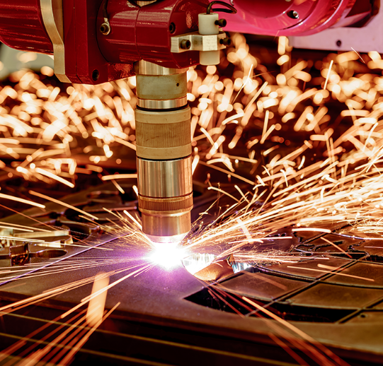
Лазерне різання тонкого металу: керівництво, яке ваш постачальник ніколи вам не надав
Що вважається тонким металом у лазерному різанні
Чи замислювались ви колись, чому ваші лазерні налаштування ідеально працюють на одному аркуші, але на іншому утворюють обгорілі краї? Відповідь часто полягає у розумінні того, що саме означає термін «тонкий метал» у контексті лазерного різання листового металу. Дивно, але більшість постачальників обладнання ніколи чітко не визначають цей критичний поріг — залишаючи операторів вирішувати це методом дорогого проб і помилок.
Визначення діапазонів товщини тонкого металу
У професійних застосуваннях лазерного різання тонкий метал зазвичай означає матеріали товщиною від 0,5 мм до 3 мм у цьому не випадковий діапазон — він відображає зону, де динаміка різання принципово відрізняється від різання більш товстих плит. Згідно з промисловими таблицями товщин від провідних виробників, таких як KF Laser матеріали цього діапазону можна ефективно обробляти за допомогою лазерів з нижчою потужністю (1000 Вт – 2000 Вт), забезпечуючи точні, чисті розрізи з мінімальною зоною термічного впливу.
Працюючи на лазерному верстаті з тонкими металевими деталями, розуміння цих категорій допомагає відразу встановити правильні параметри обробки:
- Ультратонкі листи (0,5 мм – 1 мм): Дуже схильні до теплового короблення та пробоїв; вимагають точного регулювання потужності та більш високих швидкостей різання
- Стандартні тонкі листи (1 мм – 2 мм): «Ідеальна зона» для більшості операцій лазерного різання листового металу; забезпечує оптимальний баланс між швидкістю та якістю кромки
- Верхній діапазон тонких листів (2 мм – 3 мм): Поведінка наближається до поведінки середньої товщини; для досягнення оптимальних результатів може знадобитися трохи знижена швидкість різання
Чому для різання тонкого металу потрібні інші підходи
Ось що більшість керівництв вам не розповідає: фізика лазерного різання металевих листів різко змінюється в діапазоні тонких матеріалів. На відміну від більш товстих плит, які ефективно поглинають і розсіюють тепло, тонкі листи концентрують теплову енергію в меншому об’ємі. Це створює унікальні виклики — і можливості.
Подумайте про це так: коли ви нарізаєте товстий стейк порівняно з тонким шматочком м’яса, техніка використання ножа повністю відрізняється. Те саме правило діє й тут. Працюючи з тонкими металевими деталями, ви маєте справу з:
- Швидшим теплопереносом: Увесь лист швидко нагрівається, що збільшує ризик деформації
- Зменшеними вимогами до ширини різу: Потрібно видалити менше матеріалу, що дозволяє забезпечити більш жорсткі допуски
- Вищим потенціалом точності: При оптимальному налаштуванні параметрів тонкі матеріали забезпечують надзвичайно чисті кромки
- Більшою чутливістю до змін параметрів: Невеликі коригування призводять до помітних відмінностей у якості різання
Чи ви професійний працівник промисловості, що здійснює високопродуктивне виробництво, чи хобіст, який експериментує з обробкою металу, — розуміння цих відмінностей є першим кроком до оволодіння різанням тонколистових матеріалів. У наступних розділах ви знайдете конкретні методики й параметри, які не наводяться в інструкції вашого постачальника.
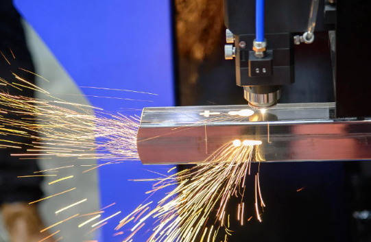
Волоконний лазер проти CO₂-лазера для тонких листів
Отже, ви вже підібрали оптимальні параметри різання для тонких металевих листів — але чи використовуєте ви взагалі правильну лазерну технологію? Це питання ставить у глухий кут як новачків, так і досвідчених операторів. Справа в тому, що волоконні та CO₂-лазери поводяться дуже по-різному під час обробки тонких листів, і вибір неправильної технології може звести нанівець навіть найкращі параметри різання.
Переваги волоконного лазера для різання тонких листів
Щодо застосування в різанні тонких металевих листів, волоконна лазерна різальна машина забезпечує експлуатаційні переваги, які важко ігнорувати. Числові дані говорять самі за себе: згідно з Аналіз технологій EVS Metal за 2025 рік , волоконні лазери забезпечують швидкість різання до 100 метрів на хвилину на тонких матеріалах — приблизно в 3–5 разів швидше, ніж еквівалентні системи на CO₂. Зокрема для роботи з тонкими листами ця перевага у швидкості безпосередньо перетворюється на вищу продуктивність і зниження витрат на один виріб.
Але швидкість — не єдина перевага. Волоконний лазер для різання металу працює з ККД, що становить приблизно 50 % від споживаної електроенергії, порівняно з лише 10–15 % для систем на CO₂. Що це означає для вашого виробництва? Витрати на енергію зменшуються з приблизно $12,73 на годину (CO₂) до $3,50–4,00 (волоконний лазер) — скорочення на 70 %, яке швидко накопичується протягом виробничих циклів.
Ось де обробка тонких металів справді виблискує завдяки волоконним технологіям:
- Зменшені зони термічного впливу: Концентрована довжина хвилі 1064 нм мінімізує теплове розповсюдження — це критично важливо для запобігання деформації тонких листів
- Вища якість променя: Більш точна фокусування забезпечує вужчі різи та чистіші краї на матеріалах товщиною менше 3 мм
- Здатність різання відбивних металів: Алюміній, мідь та латунь — матеріали, які традиційно важко різати системами на CO₂ — ефективно ріжуться за допомогою волоконного лазера для різання металу
- Знижений обсяг технічного обслуговування: Менше 30 хвилин щотижня порівняно з 4–5 годинами для систем на основі CO₂, згідно з Esprit Automation
Розуміння обмежень довжини хвилі CO₂ при різанні металу
Чому лазерний верстат на основі CO₂ погано справляється з різанням тонких листів порівняно з волоконним лазером? Відповідь полягає в фізиці довжини хвилі. Лазери CO₂ випромінюють на довжині хвилі 10 600 нм — такій довжині хвилі метали поглинають енергію неефективно. Відбивні матеріали, такі як алюміній і мідь, відбивають значну частину цієї енергії назад, що зменшує ефективність різання й потенційно пошкоджує генератор.
Труби технологія CO₂-лазерів для різання також стикається з практичними труднощами при роботі з тонкими металевими заготовками. Система подачі променя базується на дзеркалах, розташованих у гармошкоподібних захисних чохлах («балончиках»), які з часом деградують через теплову деформацію та вплив навколишнього середовища. Як пояснює компанія Esprit Automation, це призводить до змін якості променя та його потужності — серйозна проблема, коли для різання тонких матеріалів потрібні стабільні й точні параметри.
Врахуйте проблему вирівнювання: системи на основі CO₂ зазвичай вимагають регулювання щонайменше трьох дзеркал після зіткнення або втрати вирівнювання, тоді як для лазерного різального верстата з волоконним лазером для металу потрібне лише регулювання одного об'єктива. У роботі з тонкими листами, де точність має першочергове значення, ця простота має істотне значення.
| Чинник продуктивності | Ласер з волокна | Лазер CO2 |
|---|---|---|
| Швидкість різання (тонкий метал) | До 100 м/хв | 20–30 м/хв |
| Енергоефективність | ~50 % електричної потужності | 10–15 % електричної потужності |
| Вартість експлуатації/година | $3.50-4.00 | ~$12.73 |
| Тижневе обслуговування | <30 хвилин | 4-5 годин |
| Якість кромки (0,5–3 мм) | Відмінними | Добре |
| Відбиваючі метали | Відмінна (алюміній, мідь, латунь) | Погане до задовільного |
| Доставка променя | Оптоволоконна (захищена) | Дзеркальна система (відкрита) |
Чи означає це, що лазери на основі CO₂ зовсім не застосовуються у різанні металу? Не зовсім — вони й надалі добре працюють із більш товстими плитами завтовшки понад 25 мм, де якість кромки має перевагу над швидкістю. Однак у діапазоні тонких металів, про який йде мова (0,5–3 мм), волоконний лазерний різальний верстат для металу постійно перевершує аналоги на основі CO₂ за швидкістю, ефективністю та якістю різання. Розуміння цієї відмінності допомагає приймати розумніші рішення щодо обладнання та оптимізувати параметри різання відповідним чином.
Параметри різання різних тонких металів
Тепер, коли ви розумієте, чому технологія волоконного лазера домінує при обробці тонких листів, перейдемо до практичних рекомендацій, які ігноруються у керівництві вашого постачальника. Налаштування правильних параметрів для вашого лазерного верстата для різання металу — це не вгадування, а системний процес, заснований на властивостях матеріалу, його товщині та бажаній якості зрізу. У наступних розділах детально роз’яснюється все, що вам потрібно знати.
Параметри потужності та швидкості за типом матеріалу
Ось реальність: кожен лазерна машина для розрізу металу працює трохи по-різному залежно від його оптичної системи, якості лазерного променя та калібрування. Наведені нижче параметри є перевіреними початковими значеннями для волоконних лазерів потужністю 1000–3000 Вт. Використовуйте їх як базові значення, а потім точно налаштовуйте параметри на основі пробних різів.
Під час лазерного різання сталевого листа ви помітите, що низьковуглецева сталь поводиться передбачуваніше, ніж нержавіюча сталь або алюміній. Це пояснюється тим, що вуглецева сталь ефективно поглинає лазерну енергію й забезпечує стабільний потік розплаву. Для лазерного різання нержавіючої сталі потрібні інші підходи: вміст хрому утворює більш стійкі оксидні шари, що впливають на якість кромок і обмежують швидкість різання.
| Матеріалу | Товщина | Потужність (%) | Швидкість (мм/с) | Тип газу | ТИСК (БАР) |
|---|---|---|---|---|---|
| М'яка сталь | 0.5мм | 30-40% | 80-100 | O₂ | 3-5 |
| 1.0мм | 40-50% | 60-80 | O₂ | 4-6 | |
| 2.0мм | 60-70% | 35-50 | O₂ | 5-7 | |
| 3.0мм | 80-90% | 20-30 | O₂ | 6-8 | |
| Нержавча сталь (304) | 0.5мм | 35-45% | 70-90 | N₂ | 10-12 |
| 1.0мм | 50-60% | 50-65 | N₂ | 12-14 | |
| 2.0мм | 70-80% | 25-40 | N₂ | 14-16 | |
| 3.0мм | 85-95% | 15-25 | N₂ | 16-18 | |
| Алюмінії | 0.5мм | 40-50% | 90-120 | N₂ | 12-15 |
| 1.0мм | 55-65% | 60-80 | N₂ | 14-16 | |
| 2.0мм | 75-85% | 35-50 | N₂ | 16-18 | |
| 3.0мм | 90-100% | 20-30 | N₂ | 18-20 | |
| Мідь | 0.5мм | 50-60% | 50-70 | N₂ | 14-16 |
| 1.0мм | 70-80% | 30-45 | N₂ | 16-18 | |
| 2.0мм | 90-100% | 15-25 | N₂ | 18-20 | |
| Латунь | 0.5мм | 45-55% | 60-80 | N₂ | 12-14 |
| 1.0мм | 60-70% | 40-55 | N₂ | 14-16 | |
| 2.0мм | 80-90% | 25-35 | N₂ | 16-18 |
Зверніть увагу, що при лазерному різанні низьковуглецевої сталі використовується допоміжний газ — кисень, тоді як для лазерного різання НС (нержавіючої сталі) і налаштування лазерного різака для алюмінію необхідний азот. Це не випадково: кисень вступає в екзотермічну реакцію з вуглецевою сталлю, додаючи додаткову енергію для різання, тоді як азот забезпечує інертний захист, що запобігає окисленню кромок нержавіючої сталі й алюмінію.
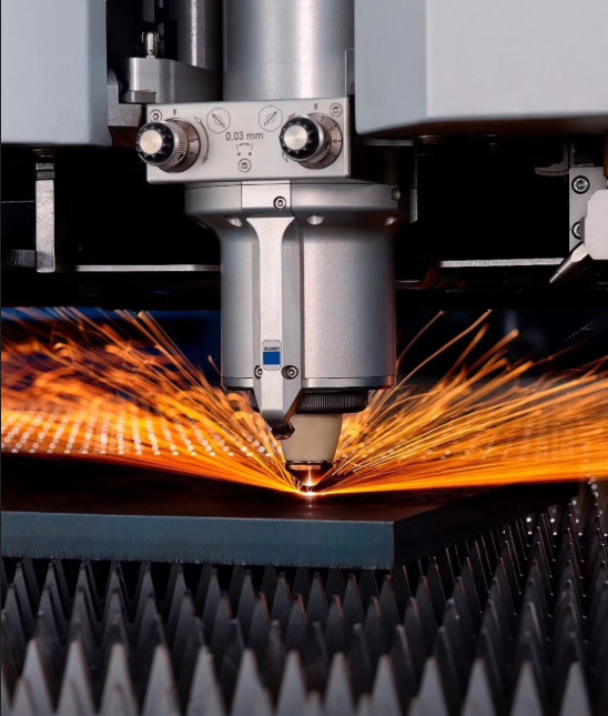
Оптимізація фокусної точки для чистих кромок
Звучить складно? Не обов’язково. Положення фокусної точки — це просто місце, де лазерний промінь досягає найменшого й найбільш концентрованого діаметра. Згідно з Настановами Xianming Laser щодо регулювання фокусу сучасні головки для різання волокна зазвичай мають діапазон регулювання 20 мм із позначками шкали від +8 (фокусна точка всередині сопла) до –12 (фокусна точка нижче поверхні сопла).
Ось ключове розуміння, яке часто упускають більшість операторів: різні матеріали вимагають різних стратегій фокусування навіть при однаковій товщині.
- Нульове фокусування (шкала 0): Фокусна точка розташована на поверхні сопла. Ідеально підходить для різання тонких металевих листів, де важлива збалансована продуктивність — гарна початкова точка для матеріалів товщиною менше 1 мм.
- Позитивне фокусування (+1 до +3): Фокусна точка зміщується всередину сопла, над поверхнею матеріалу. Рекомендовано для різання вуглецевої сталі, щоб покращити якість верхньої поверхні та зменшити розбризкування.
- Негативне фокусування (–1 до –4): Фокусна точка опускається нижче поверхні матеріалу. Необхідно для лазерного різання нержавіючої сталі та алюмінію, щоб отримати чисті краї без заусенців.
Уявіть, що ви фокусуєте збільшувальне скло на аркуші паперу: якщо розташувати його занадто близько або занадто далеко, сфокусована точка розпливеться. Те саме принципово застосовується й тут. Для тонких листів навіть зміщення фокусу на 0,5 мм може означати різницю між полірованим краєм і краєм, покритим шлаком.
| Тип матеріалу | Рекомендована позиція фокусу | Очікуваний результат |
|---|---|---|
| Вуглецева сталь (0,5–3 мм) | +1 до +2 (позитивне) | Чистий верхній край, мінімальне розбризкування, ефективна реакція з киснем |
| Нержавіюча сталь (0,5–3 мм) | -1 до -3 (негативне) | Блискучі краї без оксидів, зменшення утворення заусенців |
| Алюміній (0,5–3 мм) | -2 до -4 (негативне) | Гладкі розрізи, мінімізація прилипання шлаку |
| Мідь (0,5–2 мм) | –1 до –2 (негативне значення) | Стабільне проникнення навіть при високій відбивній здатності |
| Латунь (0,5–2 мм) | –1 до –2 (негативне значення) | Чисті краї, зменшення проблем, пов’язаних з випаровуванням цинку |
Один практичний порада: перед початком будь-якого виробничого циклу виконайте тест фокусування — виріжте серію коротких ліній, змінюючи положення фокусу з кроком 0,5 мм. Огляньте зрізані краї за гарного освітлення: налаштування, що забезпечує найгладшу й найстабільнішу кромку, є оптимальним для фокусування саме для цього матеріалу та його товщини.
Ці базові параметри добре підійдуть для більшості застосувань у роботі з тонкими металами. Однак навіть ідеальні налаштування не зможуть компенсувати використання неправильного допоміжного газу — а це веде нас до критично важливої теми, яку більшість навчальних матеріалів зовсім ігнорують.
Вибір допоміжного газу для оптимальних результатів
Ви налаштували параметри потужності та оптимізували положення фокусу, але існує один чинник, який може визначити успіх або невдачу роботи з тонкими листами: вибір допоміжного газу. Дивовижно, але цей критичний параметр майже не розглядається у більшості інструкцій до обладнання, через що оператори змушені дізнаватися на власному досвіді, що неправильний вибір газу руйнує інакше ідеальні різи.
Кисень проти азоту для контролю якості зрізу
Ось основна відмінність: кисень — реактивний газ, а азот — інертний. Ця різниця створює принципово різні динаміки різання під час лазерного різання металу на тонких листах.
Коли кисень взаємодіє з розплавленою сталлю, відбувається екзотермічна реакція — газ буквально додає енергії до процесу різання. Згідно з Технічним аналізом Metal-Interface ця хімічна реакція в поєднанні з механічною дією забезпечує відмінну ефективність різання вуглецевої сталі. Компроміс? Окислення по краю різу призводить до трохи сіруватого відтінку, що може вимагати додаткової обробки, наприклад, зачистки щіткою, шліфування або хімічної обробки.
Різання азотом працює інакше — воно чисто механічне. У налаштуванні лазерного металорізального устаткування з використанням азоту розплавлений матеріал просто віддувається без будь-якої хімічної реакції. Результат? Чисті, вільні від оксидів краї, які виглядають блискучими й гладкими. Як пояснює Жан-Люк Маршан із компанії Messer France: «Сьогодні ринкова тенденція полягає у використанні єдиного багатофункціонального джерела газу — азоту» через його універсальність при роботі з різними матеріалами.
Кисень як допоміжний газ
- Про: Висока швидкість різання вуглецевої сталі; сильна проникаюча здатність; нижчі вимоги до тиску (приблизно 2 бари); знижена витрата газу (~10 м³/год)
- Недоліки: Спричиняє окислення країв, що вимагає додаткової обробки; застосовується лише для сталевих матеріалів; не підходить для нержавіючої сталі, алюмінію чи відбивних металів
Азот як допоміжний газ
- Про: Чисті, вільні від оксидів «світлі» краї; працює з усіма матеріалами, включаючи нержавіючу сталь, алюміній, мідь та латунь; зазвичай не вимагає додаткової обробки; універсальне рішення з використанням одного газу
- Недоліки: Вищі вимоги до тиску (22–30 бар); збільшена витрата (~40–120 м³/год); швидкість різання приблизно на 30 % нижча порівняно з різанням киснем по сталі
Для застосувань з тонкими листами азот часто стає переважним варіантом, навіть попри його вищу витрату. Чому? Коли ви працюєте з матеріалами товщиною менше 3 мм, якість країв стає більш помітною — будь-яке окиснення виявляється одразу. Крім того, різниця в швидкості має менше значення для тонких листів, оскільки різання завершується швидко незалежно від вибору газу.
Коли стиснене повітря підходить для тонких листів
Ось що багато операторів не усвідомлюють: стиснене повітря містить приблизно 78 % азоту та 21 % кисню, тому його можна розглядати як гібридний варіант для певних застосувань. Згідно з Керівництво FINCM щодо вибору газу , ця бюджетна альтернатива особливо добре підходить для алюмінієвих листів і оцинкованої сталі.
Уявіть стиснене повітря як економічну «золоту середину». Ви жертвуєте певною якістю зрізу на користь суттєвого зниження витрат — без оренди балонів, без проблем із логістикою поставок, лише ваша наявна інфраструктура компресора. Для хобі-проектів або неважливих виробничих партій такий підхід до лазерного різання металу є практичним рішенням.
Сціслене повітря
- Про: Найнижча експлуатаційна вартість; відсутність логістики закупівлі газу; зменшення утворення оксидного шару на певних матеріалах; легко доступне в більшості майстерень
- Недоліки: Якість кромки гірша порівняно з чистим азотом; не рекомендується для товстих плит або точних робіт; вимагає належної фільтрації для видалення вологи й забруднення маслом
| Тип газу | Найкраще застосування | Типовий тиск | Швидкість споживання | Обробка краю |
|---|---|---|---|---|
| КИСЕНЬ (O₂) | Вуглецева сталь, конструкційна сталь | 2–6 бар | ~10 м³/годину | Окислена (сіра) |
| Азот (N₂) | Нержавіюча сталь, алюміній, мідь, латунь | 22–30 бар | 40-120 м³/годину | Яскрава, без оксидів |
| Сціслене повітря | Алюміній, оцинкована сталь, тонкі листи | 8–12 бар | Залежить від компресора | Середня якість |
Одна важлива заувага щодо чистоти газу: хоча виробники іноді вказують рівні чистоти, що перевищують стандартні показники, експерти компаній Air Liquide та Messer зазначають, що для більшості лазерних застосувань у різанні металів цілком підходить стандартна якість азоту (чистота 99,995 %). Справжній ризик забруднення походить від мережі подачі — неправильно встановлені трубопроводи можуть вносити частинки, які пошкоджують оптику або впливають на якість різання.
Правильний вибір допоміжного газу закладає основу для успіху, але що робити, якщо проблеми все ж виникають? Навіть за оптимальних параметрів і правильного вибору газу різання тонких металевих листів створює унікальні виклики, що вимагають спеціалізованих підходів до усунення несправностей.
Усунення типових проблем при різанні тонких металів
Ви оптимізували параметри, вибрали правильний допоміжний газ і правильно розмістили фокусну точку — але різання тонких листів все ще не виходить як потрібно. Це знайомо? Ви не самі. Лазерне різання металу на тонких матеріалах створює унікальні виклики, з якими навіть досвідчені оператори стикаються регулярно. Різниця між роздратуванням і успіхом часто залежить від уміння розпізнавати певні типові проблеми й застосовувати цільові рішення.
Обговорення на форумах показують, що ті самі запитання з’являються знову й знову: чому мої тонкі листи закручуються, наче чіпси? Що викликає ту непереборну кірку, що залишається на зворотному боці? Як позбутися шорстких, зубчастих кромок? У цьому розділі надається практичний посібник із усунення несправностей, який ваш постачальник ніколи не надавав — реальні рішення, отримані з практичного досвіду й технічної експертизи.
Запобігання тепловому коробленню тонких листів
Деформація внаслідок нагрівання є найпоширенішою скаргою під час лазерного різання металів із тонких матеріалів. Згідно з технічним аналізом компанії SendCutSend, деформація виникає, коли внутрішні напруження в матеріалі втрачають баланс — або через введення нових теплових напружень, або через видалення ділянок уже напруженого матеріалу під час процесу різання.
Ось що найчастіше упускають з уваги оператори: той гарний рівний лист металу, який ви завантажуєте в свою лазерну систему для різання металів, вже містить внутрішні напруження, що виникли під час виробництва. Під час виготовлення листового металу його виливають із рідкого стану, пропускають через матриці та ролики, намотують у рулони для транспортування, а потім знову розрівнюють перед тим, як він потрапляє до вас. Кожен із цих етапів створює напруження, яке залишається врівноваженим — доки ваш лазер не почне видаляти матеріал.
Поширені причини деформації
- Надмірна концентрація тепла: Тонкі листи завтовшки менше 3 мм швидко нагріваються, оскільки теплова енергія концентрується в меншому об’ємі з меншою масою для поглинання та розсіювання
- Високий відсоток видалення матеріалу: Видалення більше ніж 50 % матеріалу з аркуша значно підвищує ймовірність деформації через зміну балансу внутрішніх напружень
- Мережеві або сітчасті візерунки: Конструкції з обширними вирізами створюють нерівномірний розподіл напружень по залишковому матеріалу
- Довгі та тонкі форми: Вузькі елементи не мають достатньої структурної жорсткості, щоб протистояти тепловій деформації під час різання
Практичні рішення для запобігання деформації
- Використовуйте імпульсний режим різання: Імпульсне лазерне випромінювання зменшує постійний тепловий вплив, дозволяючи тонкому матеріалу охолоджуватися між імпульсами й мінімізуючи накопичення тепла
- Збільште швидкість різання: Більш висока швидкість переміщення зменшує час перебування в будь-якій окремій точці, обмежуючи локальне накопичення тепла — хоча це потрібно узгодити з якістю зрізу
- Збільште ширину містка: Під час різання деталей із інтенсивним видаленням матеріалу ширші контурні лінії та з’єднувальні містки сприяють збереженню площинності протягом процесу різання
- Додайте фіксуючі перемички: Малі нерозрізані перемички (приблизно 2 × товщина матеріалу) між деталями та навколишнім листом запобігають зміщенню й рівномірніше розподіляють напруження
- Розгляньте альтернативні матеріали: Нержавіюча сталь деформується легше, ніж низьковуглецева сталь або алюміній; композитні матеріали часто забезпечують кращу розмірну стабільність для критичних застосувань
- Проектуйте з урахуванням жорсткості: Деталі з загнутими фланцями, ребрами жорсткості або вм’ятинами краще опорюються деформації, ніж повністю плоскі конструкції
Один важливий факт: іноді деформація виникає навіть попри всі ваші зусилля. Як зазначає SendCutSend, одне й те саме конструкторське рішення може бути ідеально вирізано під час одного циклу й суттєво деформуватися під час наступного — залежно від стану внутрішніх напружень конкретного листа. Коли деформація все ж виникає, це не означає, що деталь безнадійно пошкоджена: багато деформованих деталей можна відновити шляхом згинання до потрібної форми або вони природним чином вирівнюються під час збирання разом з іншими компонентами.
Усунення проблеми пробою та утворення шлаку
Пробій та утворення шлаку є протилежними проявами однієї й тієї самої проблеми — неправильна подача енергії в зону різання. Надмірна енергія призводить до пробою; недостатня енергія або погана екстракція матеріалу спричиняють утворення шлаку. Володіння технологією лазерного різання металевих листів означає розуміння обох типів відмов.
Пробій на надтонких матеріалах
Якщо замість чистих різів ви бачите отвори, надмірне плавлення або обгорілі краї, це означає, що ваші лазерні верстати для різання металу подають більше енергії, ніж може витримати тонкий матеріал. Згідно з посібником з усунення несправностей компанії JLCCNC, сліди опіків і потемніння зазвичай виникають через надто високі параметри потужності, особливо в кутах або на ділянках складної геометрії, де різальна головка зменшує швидкість руху.
- Знизьте вихідну потужність: Для матеріалів товщиною менше 1 мм починайте з 30–40 % потужності й підвищуйте її лише в разі непостійного проплавлення
- Збільште швидкість різання: Підвищення швидкості переміщення розподіляє енергію на більшій довжині матеріалу, зменшуючи локальне перегрівання
- Перейти на азот як допоміжний газ: Кисень викликає екзотермічні реакції, що додають енергію; азот забезпечує інертне захистне середовище без додаткового теплового впливу
- Використовувати кілька проходів з низькою потужністю: Замість одного агресивного різання розгляньте кілька легших проходів, що поступово видаляють матеріал
- Налаштувати параметри кутів: Багато лазерних верстатів для різання металу дозволяють зменшити потужність або встановити паузу в кутах, щоб запобігти накопиченню енергії в тісній геометрії
Утворення шлаку та його прилипання
Цей упертий розплавлений матеріал, що залишається на зворотному боці лазерно вирізаного листового металу? Це — шлак, і він ускладнює процес очищення, а також заважає точному монтажу деталей. Шлак утворюється, коли розплавлений матеріал недостатньо ефективно видаляється з зони різання.
- Збільште тиск допоміжного газу: Підвищений тиск забезпечує більшу механічну силу для видалення розплавленого матеріалу з зони різання
- Перевірити стан сопла: Зношені або пошкоджені сопла порушують шаблони потоку газу, знижуючи ефективність викиду
- Перевірте відстань між соплом і поверхнею матеріалу: Зазор між соплом і поверхнею матеріалу впливає як на газову динаміку, так і на фокусування променя — зазвичай 0,5–1,5 мм для роботи з тонкими листами
- Використовуйте підвищені опори для різання: Опори у вигляді решіток або сотоподібні ложа дозволяють шлаку вільно відпадати, а не зварюватися до опорних поверхонь
- Налаштуйте положення фокусу: Негативне фокусування (фокусна точка розташована нижче поверхні матеріалу) часто покращує видалення шлаку при різанні нержавіючої сталі та алюмінію
Рішення проблем з якістю кромки
Шорсткі кромки, помітні смуги або нерівномірні лінії різання вказують на невідповідність параметрів або технічні несправності обладнання, а не на внутрішні проблеми матеріалу. Згідно з аналізом JLCCNC, ці дефекти якості найчастіше пов’язані з забрудненням оптичних компонентів, неправильними швидкостями подачі або механічними вібраціями.
- Очистіть оптичні компоненти: Брудні лінзи, дзеркала та коліматори погіршують якість лазерного променя — встановіть регулярний графік очищення на основі нароблених годин роботи
- Зменшити механічні вібрації: Розбалансовані компоненти, зношені підшипники або недостатня маса столу призводять до нерівностей різального контуру; за необхідності використовуйте демпфери або уважно зафіксуйте заготовку вантажем
- Підібрати параметри відповідно до товщини: Універсальні налаштування рідко забезпечують оптимальну обробку матеріалів певної товщини — виконайте пробні різи й систематично скоригуйте параметри
- Перевірити вирівнювання променя: Невирівнені різальні головки призводять до непостійної ширини різального шва та кутів обробленого краю по всій площині різального столу
- Перевірити рівність матеріалу: Наявні згини або хвилі в листовому матеріалі спричиняють коливання відстані фокусування, що впливає на однорідність країв
| Проблема | Основні причини | Швидкий ремонт |
|---|---|---|
| Вигинання від нагріву | Несиметричні теплові напруження, високий відсоток видалення матеріалу | Використовуйте імпульсний режим, збільште швидкість різання, додайте технологічні перемички |
| Прожог | Надмірна потужність, низька швидкість, допоміжний кисень при різанні тонких листів | Зменшити потужність на 10–20 %, перейти на азот, збільшити швидкість |
| Прилипання шлаку | Низький тиск газу, неправильна фокусувальна відстань, зношений сопло | Збільшити тиск, перевірити відстань до заготовки, замінити сопло |
| Нерівні краї | Забруднена оптика, вібрація, невідповідність параметрів | Очистити лінзу, перевірити механічні компоненти, виконати пробні різи |
| Розмірні похибки | Термічне розширення, недостатньо надійне кріплення заготовки, не врахована ширина різального шва (керф) | Зменшити швидкість, використовувати відповідні затиски, налаштувати параметри керф у CAM-програмному забезпеченні |
Пам’ятайте, що усунення несправностей при різанні тонких листів часто вимагає одночасного вирішення кількох факторів. Одного коригування зазвичай недостатньо для вирішення складних проблем якості — стабільні результати забезпечує систематична оптимізація параметрів у поєднанні з належним технічним обслуговуванням обладнання. Якщо проблеми зберігаються навіть після всіх ваших зусиль, причиною може бути неправильний вибір лазерного верстата, а не помилки оператора.
Вибір правильного лазерного верстата для тонких металів
Ви оволоділи параметрами, вибрали правильний газ і навчилися усувати типові несправності — але що робити, якщо ваше обладнання просто не підходить для роботи з тонкими металами? Вибір правильного лазерного різака для металу — це той етап, на якому багато проектів успішно реалізуються або, навпаки, проваливаються ще до першого розрізу. Незалежно від того, чи керуєте ви виробничою дільницею, чи організовуєте домашню майстерню, розуміння вимог до обладнання запобігає дорогоцінним невідповідностям між вашими цілями та можливостями обладнання.
Промислові та побутові вимоги до обладнання
Ось чесна оцінка: промислове та побутове різання тонких металів — це дуже різні сфери. Лазерний різак для листового металу, призначений для виробничих умов, робить акцент на швидкості, автоматизації та тривалому циклі роботи. У той же час лазерний різак для металу, призначений для домашнього використання, поєднує функціональність із обмеженнями щодо доступного простору, потужності електромережі та бюджету.
Промислові операції зазвичай вимагають:
- Закриті різальні камери: Вимоги щодо безпеки передбачають належне утримання, відсмоктування парів та захист оператора
- Великі розміри робочого столу: Стандартні формати 4' × 8' або більші дозволяють обробляти повні листи без необхідності їх перефіксації
- Автоматизоване оброблення матеріалів: Системи завантаження, транспортні столи та сортування деталей зменшують витрати праці під час серійного виробництва
- Надійні системи охолодження: Безперервна робота вимагає промислових чилерів, які забезпечують стабільну роботу лазера
- Інтеграція ЧПУ: Повнофункціональні програмні комплекси з оптимізацією розміщення, плануванням виробництва та контролем якості
Умови роботи для любителів та невеликих майстерень інші:
- Обмеження однофазного живлення: Більшість побутових та невеликих цехових електричних кіл мають обмеження 30–50 А, що обмежує доступну потужність лазера
- Обмеження простору: Варіанти настільних і компактних лазерних верстатів для різання металу підходять для гаражів та додаткових кімнат
- Проблеми вентиляції: Правильне видалення парів вимагає планування, коли спеціалізовані промислові приміщення недоступні
- Чутливість до бюджету: Різниця у ціні між недорогим лазерним різаком і професійним обладнанням становить десятки тисяч доларів
Один і той самий запит постійно з’являється на форумах: «Чи може мій CO₂-лазер різати тонку нержавіючу сталь?» Чесна відповідь: технічно так, але на практиці це дуже незручно. Як ми вже зазначали раніше, хвилі CO₂-лазера (10 600 нм) сильно відбиваються від металів. CO₂-лазер потужністю 100 Вт, можливо, лише залишить слід на тонкій нержавіючій сталі — для будь-якого реального різання потрібна потужність 150 Вт і більше, а навіть у цьому разі якість зрізу значно гірша порівняно з волоконними аналогами. Якщо нержавіюча сталь є вашим основним матеріалом, то лазерний різак для нержавіючої сталі означає інвестиції у волоконну технологію — без винятків.
Мінімальні вимоги до потужності для роботи з тонкими металами
Вибір потужності ґрунтується на простому принципі: підібрати лазер відповідно до максимальної товщини передбачуваного матеріалу. Згідно з Рекомендації щодо потужності ACCURL , різні матеріали та товщини вимагають певних діапазонів потужності для ефективного різання.
Для обробки тонких металів (0,5 мм–3 мм) потрібно наступне:
- волоконний лазер потужністю 500 Вт: Обробляє низьковуглецеву сталь до 2 мм, нержавіючу сталь — до 1,5 мм; підходить для легких хобі-завдань
- волоконний лазер потужністю 1000 Вт: Ріже низьковуглецеву сталь до 3 мм, нержавіючу сталь — до 2 мм, алюміній — до 2 мм; початковий рівень для серйозної обробки тонких листів
- волоконний лазер потужністю 1500–2000 Вт: Забезпечує комфортну обробку всіх тонких металів із запасом швидкості для підвищення продуктивності виробництва
- волоконний лазер потужністю 3000 Вт і більше: Промислові швидкості обробки тонких матеріалів із можливістю різання більш товстих листів за потреби
Важливий аспект, який часто ігнорують: рекламовані показники потужності вказують на максимальну вихідну потужність, а не на оптимальні умови експлуатації. Постійна робота будь-якого лазерного металорізального верстата на 100 % потужності прискорює знос компонентів і скорочує термін його служби. Верстат потужністю 1500 Вт, що працює з навантаженням 70 %, часто забезпечує кращі результати, ніж верстат потужністю 1000 Вт, що працює на повну потужність, — при цьому маючи довший термін служби.
| Категорія машини | Діапазон потужності | Підходящі тонкі метали | Типові застосування | Ціновий діапазон |
|---|---|---|---|---|
| Настільний/для хобі | 20 Вт–60 Вт, волоконний лазер | Дуже тонка латунь, мідна фольга, алюміній завтовшки менше 0,5 мм | Виробництво прикрас, дрібні прототипи, гравірування | $3,000-$15,000 |
| Початковий професійний рівень | 500 Вт–1000 Вт, волоконний лазер | Сталь звичайна до 3 мм, нержавіюча сталь до 2 мм, алюміній до 2 мм | Малий виробничий цех, виготовлення вивісок, спеціальні деталі | $15,000-$40,000 |
| Промисловий верстат середнього класу | 1500 Вт–3000 Вт, волоконний | Усі тонкі метали зі швидкістю виробництва | Майстерні замовлення, постачальники автокомпонентів, металообробні підприємства | $40,000-$100,000 |
| Високопродуктивне | 4000 Вт–12000 Вт, волоконний | Тонкі метали з максимальною швидкістю, а також можливість різати товсті листи | Виробництво великих партій, авіакосмічна промисловість, важке металообробне виробництво | $100,000-$500,000+ |
Розміри робочого столу заслуговують такої ж уваги. Лазерний різак для листового металу, який може обробляти лише заготовки розміром 600 мм × 400 мм, змушує вас спочатку розрізати великі листи на частини — що збільшує час обробки й ризик помилок при вирівнюванні. Стандартні промислові столи мають розміри 1500 мм × 3000 мм (приблизно 5 футів × 10 футів), однак компактні моделі розміром 1300 мм × 900 мм ефективно задовольняють потреби багатьох малих підприємств.
Крім потужності та розмірів, для роботи з тонкими металами надавайте перевагу таким функціям:
- Автоматична фокусування: Необхідно для підтримки оптимального фокусного положення при різних товщинах матеріалу без ручної корекції
- Якісна різальна головка: Преміальні головки від таких виробників, як Precitec або Raytools, забезпечують кращу стабільність лазерного променя порівняно з бюджетними аналогами
- Жорстка рамна конструкція: Вібрації під час різання спричиняють проблеми з якістю кромки — важчі й жорсткіші рами забезпечують чистіші результати
- Належна система витяжки: Різання тонкого металу утворює дрібні частинки, для яких потрібна достатня потужність фільтрації
Головне? Підбирайте верстат відповідно до ваших реальних потреб, а не бажаних. Адекватно підібраний лазерний різак початкового рівня для обробки листового металу завжди перевершує надмірно дорогий, але недостатньо потужний агрегат. Тепер, коли ви розумієте, як вибирати обладнання, можливо, вас цікавить, як лазерне різання порівнюється з іншими методами обробки тонкого металу.
Лазерне різання проти хімічного травлення тонкого металу
Тепер, коли ви обрали правильне обладнання, варто задати собі таке запитання: чи є лазерне різання завжди найкращим підходом для тонких металевих деталей? Відповідь може вас здивувати. Хімічне травлення — процес, що використовує фотополімерні маски та контрольовані кислотні ванни, — безпосередньо конкурує з лазерним різанням у сегменті тонких листових матеріалів. Розуміння того, у яких випадках кожен із цих методів дає кращі результати, допоможе вам приймати розумніші виробничі рішення замість того, щоб автоматично вибирати той процес, з яким ви найбільш знайомі.
Коли лазерне різання перевершує хімічне травлення
Давайте розберемося в суті: лазерний верстат для різання листового металу забезпечує чіткі переваги в певних ситуаціях, які хімічне травлення просто не в змозі забезпечити. Згідно з Детальним порівнянням компанії E-Fab , обидва методи дозволяють виготовлювати точні деталі — але вони досягають найкращих результатів у принципово різних сценаріях.
Ось де ваш лазерний верстат для різання листового металу однозначно перемагає:
- Швидке прототипування та одиничні вироби: Потрібна одна деталь або невелика партія вже сьогодні? Лазерне різання не вимагає підготовки інструментів — завантажте свій CAD-файл і одразу почніть різати. Для хімічного травлення перед початком обробки потрібно створити фотомаску
- Здатність обробляти більш товсті матеріали: Хімічне травлення працює найкраще з матеріалами товщиною менше 1,5 мм, тоді як лазерні системи для різання металу обробляють повний діапазон тонких металів (0,5–3 мм) без втрати якості
- Гнучкість дизайну: Зміна конструкції деталі не коштує нічого при лазерному різанні — просто змініть файл. Для хімічного травлення потрібні нові маски при кожній редакції, що збільшує терміни виконання й витрати
- Тривимірні елементи: Лазерне різання формує перпендикулярні краї на всю товщину матеріалу. Хімічне травлення створює характерні «зубчасті» профілі, де верхній і нижній шаблони травлення зустрічаються
- Всеохватність матеріалів: Установка для лазерного різання листового металу може обробляти практично будь-який метал. Хімічне травлення обмежене матеріалами, сумісними з певними хімічними складами травильних розчинів
Уявіть, що ви розробляєте новий дизайн кронштейна — створення прототипів за допомогою лазерного різання дозволяє вам виконати кілька ітерацій за один день. Той самий процес із використанням хімічного травлення вимагав би нових фотомасок для кожної редакції, що потенційно збільшило б тривалість вашого циклу розробки на кілька днів.
Розгляд обсягів та складності
Ось чесна правда: хімічне травлення має справжні переваги для певних застосувань. Згідно з Технічним аналізом Metal Etching , цей процес особливо ефективний, коли потрібно виготовити велику кількість ідентичних деталей із надтонкими елементами.
Ключова відмінність полягає в тому, як кожен із цих процесів масштабується. Лазер ріже по одному контуру за раз — більша кількість деталей означає просто більше часу різання. Хімічне травлення ж працює одночасно з усім аркушем, обробляючи десятки чи навіть сотні деталей за одну партію, незалежно від їхньої кількості. Для серійного виробництва понад кількох сотень ідентичних виробів ця можливість паралельної обробки часто робить травлення економічно вигіднішим варіантом.
Розгляньте такі критерії прийняття рішення:
- Вимоги до розмірів елементів: Хімічне травлення дозволяє отримувати елементи розміром до 30 мікрометрів — тонші, ніж може забезпечити більшість лазерно вирізаних металевих листів без спеціального обладнання
- Обробка без напружень: Лазерне різання створює зони, вплив яких пов’язаний із нагріванням, що може змінювати властивості матеріалу. Хімічне травлення видаляє матеріал без теплового або механічного навантаження — це критично важливо для прецизійних компонентів, таких як диски енкодерів або пластина паливних елементів
- Безбуртові краї: Правильно виконане хімічне травлення призводить до природно гладких кромок, які не потребують додаткової обробки. При лазерному різанні може залишатися шлак або мікрозаусіння, що вимагають подальшої очистки
- Стабільна якість партії: Кожна деталь у партії, виготовленій методом хімічного травлення, піддається однаковим умовам обробки. Деталі, вирізані лазером, можуть мати незначні відмінності між першою та останньою деталлю через накопичення тепла
| Фактор прийняття рішення | Перевага лазерного різання | Перевага хімічного травлення |
|---|---|---|
| Швидкість створення прототипу | Негайне виконання — без необхідності виготовлення інструментів | Потребує створення фотомаски (1–3 дні) |
| Виробництво великого обсягу | Лінійне масштабування (більше часу на деталь) | Паралельна обробка (ефективність партії) |
| Товщина матеріалу | 0,5 мм до 25 мм і більше залежно від потужності | Найкраще — до 1,5 мм, максимум ~2 мм |
| Мінімальний розмір елемента | ~0,1–0,2 мм типово | досяжна точність 30 мікрометрів |
| Профіль краю | Перпендикулярні, чисті розрізи | Профіль «вершини» внаслідок травлення з обох сторін |
| Термічний стрес | Присутні зони термічного впливу | Без напружень, без термічного впливу |
| Зміни у конструкції | Зміна лише файлу | Потрібна нова фотомаска |
| Час виконання | Для прототипів можливо в той самий день | Зазвичай 1–2 тижні для виробництва |
| Ефективність витрат | Краще підходить для низьких і середніх обсягів | Краще підходить для великих обсягів (1000+ деталей) |
Практичний висновок? Жоден із процесів не є універсально кращим. Для розробки продукту, спеціального виготовлення та партій до кількох сотень штук лазерне різання зазвичай переважає за швидкістю й гнучкістю. Для масового виробництва деталей з надтонкими елементами — сітчастих фільтрів, контактних площадок (lead frames), прецизійних прокладок — хімічне травлення часто забезпечує кращу економічну ефективність і стабільність.
Багато виробників підтримують стосунки як із постачальниками лазерного різання, так і з постачальниками хімічного травлення, вибираючи оптимальний процес для кожного проекту залежно від обсягів, складності та термінів виконання. Розуміння обох варіантів дозволяє вам приймати обґрунтовані рішення замість того, щоб примусово застосовувати єдиний метод виробництва до всіх випадків. Щодо обґрунтованих рішень — розуміння практичних застосувань допомагає проілюструвати, у яких випадках лазерне різання тонких металів забезпечує надзвичайну цінність.
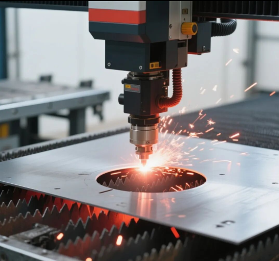
Промислові застосування лазерного різання тонких металів
Розуміння вибору обладнання та порівняння процесів надає цінний контекст — але спостереження за тим, як лазерне різання тонких металів працює в реальних умовах виробництва, пояснює, чому ця технологія стала незамінною в багатьох галузях. Від елементів шасі автомобілів до мікроскопічних електронних зборок лазерний верстат для різання листового металу забезпечує точність і повторюваність, яких традиційні методи виготовлення просто не можуть досягти.
Застосування в автомобільній промисловості та для компонентів шасі
Автомобільна промисловість є однією з найбільших споживачів технології лазерного різання тонких металів. Згідно з Аналізом SLTL щодо автомобільного виробництва , CNC-лазерні верстати для металу стали незамінними для виготовлення конструктивних та естетичних компонентів, які сучасні автомобілі вимагають.
Чому ця галузь так сильно залежить від обладнання для лазерного різання металу? Розгляньте вимоги: автовиробники потребують тисяч ідентичних деталей із жорсткими допусками, які виготовляються зі швидкістю, що відповідає вимогам конвеєрного виробництва. Лазерний верстат для різання сталі забезпечує саме це — точні різи з мінімальними відхиленнями протягом серій виробництва, що охоплюють десятки тисяч одиниць.
Ось де лазерне різання тонких металів переважає у автомобільній галузі:
- Компоненти шасі та рами: Бокові панелі, поперечні елементи та конструктивні підсилення вимагають чистих різів із мінімальним тепловим спотворенням. Висока точність фокусування лазерного променя дозволяє виконувати складні різи на тонколистовій сталі, зберігаючи при цьому жорсткі допуски, необхідні для безпеки транспортного засобу.
- Кузовні панелі та зовнішні деталі: Обшивки дверей, крила та елементи капота вимагають стабільної якості кромок на кожній деталі. Лазерне різання металевих заготовок забезпечує таку повторюваність, одночасно обробляючи складні контури, що визначають сучасну автомобільну естетику.
- Внутрішні конструктивні елементи: Рамки панелі приладів, кріплення сидінь та компоненти підлоги вимагають точного підгону до інших збірок. Лазерний CNC-станок для різання сталі забезпечує геометричну точність, необхідну для таких щільно прилягаючих деталей.
- Компоненти системи випуску: Теплоізоляційні екрани, монтажні кронштейни та корпуси каталізаторів потребують різання жаростійких сплавів у спеціалізованих умовах — застосувань, де лазерна технологія перевершує механічні альтернативи.
Інтеграція CNC-технології перетворює різання тонкого металу з кваліфікованої ремісничої операції на повторюваний виробничий процес. CNC-система лазерного різання металу виконує одну й ту саму траєкторію інструменту ідентично — чи то для першої деталі зміни, чи для десятитисячної, — усуваючи варіативність, притаманну ручним методам виготовлення.
Для виробників, які шукують сертифіковані автотранспортні компоненти з тонкого металу, спеціалізовані постачальники заповнюють розрив між задумом конструкторів та реалізацією у виробництві. Shaoyi Metal Technology наприклад, має сертифікат IATF 16949 — стандарт якості для автомобільної промисловості — і поєднує лазерне різання з точним штампуванням для виготовлення шасі, підвісок та конструктивних компонентів. Їхня послуга швидкого прототипування за 5 днів демонструє, як сучасні виробничі партнери скорочують цикли розробки продукції, які раніше тривали тижнями.
Точні деталі для виробництва електроніки
Хоча автотранспортні застосування демонструють потужні можливості щодо обсягів виробництва, виробництво електроніки розкриває потенціал лазерних систем різання металевих листів у забезпеченні максимальної точності. Згідно з аналізом галузі від Xometry, для електронних застосувань потрібна точність, яка вимагає від обладнання максимальної продуктивності.
Подумайте про те, що знаходиться всередині вашого смартфона або ноутбука — тонкі металеві екрани, мікро-розмірні кронштейни та точні корпуси, які мають збігатися з точністю до часток міліметра. Лазерний верстат для різання листового металу виготовляє ці компоненти з розмірною стабільністю, яку механічне різання важко забезпечити.
Основні застосування у виробництві електроніки включають:
- Захист від ЕМІ/РФІ: Тонкі металеві корпуси, що захищають чутливі схеми від електромагнітних перешкод, потребують точних отворів і монтажних елементів — ідеальні об’єкти для лазерної обробки
- Корпуси з’єднувачів: Тонкі металеві оболонки навколо USB-портів, роз’ємів живлення та інтерфейсів передачі даних вимагають чистих кромок без заусенців, які могли б завадити надійному з’єднанню
- Радіатори та система теплового управління: Тонкі алюмінієві й мідні листи, нарізані на складні ребристі структури для відведення тепла, де якість кромок безпосередньо впливає на теплову ефективність
- Підтримка виробництва друкованих плат: Лазерне свердлення створює точні отвори у друкованих платах, тоді як різальні операції виготовляють шаблони, що використовуються при нанесенні паяльної пасти
- Компоненти акумуляторів: Оскільки електромобілі та переносні електронні пристрої вимагають передових систем зберігання енергії, лазерне різання використовується для виготовлення тонких металевих струмопровідних основ, виводів та елементів корпусів для таких акумуляторів
| Промисловість | Типові застосування | Поширені матеріали | Критичні вимоги |
|---|---|---|---|
| Автомобільний | Компоненти шасі, кузовні панелі, кріпильні скоби | М’яка сталь, нержавіюча сталь, алюміній | Розмірна стабільність, можливість високого обсягу виробництва |
| Електроніка | Екранування, корпуси, радіатори, компоненти друкованих плат | Мідь, алюміній, нержавіюча сталь | Мікромасштабна точність, краї без заусенців |
| Медичні прилади | Корпуси приладів, компоненти хірургічних інструментів | Нержавча заліза, Титан | Біосумісні покриття, надзвичайна точність |
| Аерокосмічна промисловість | Кріпильні скоби, прокладки, легкі конструктивні елементи | Алюміній, титан, спеціальні сплави | Оптимізація ваги, сертифікація матеріалів |
| Споживачі продукти | Панелі побутових приладів, декоративні елементи, корпуси | Нержавіюча сталь, алюміній, латунь | Естетична якість, однорідне оздоблення |
Що об’єднує всі ці застосування? Інтеграція з ЧПУ дозволяє реалізовувати складні конструкції, які були б непрактичними — або й зовсім неможливими — за допомогою традиційних методів різання. Коли ваш лазерний різак з ЧПУ для металу виконує запрограмовану траєкторію різання, він відтворює складні геометричні форми з точністю до часток міліметра: тісні радіуси закруглень, точні шаблони отворів і складні контури, що точно відповідають геометрії з CAD.
Ця точність стає особливо важливою, коли тонкі металеві компоненти взаємодіють з іншими деталями, виготовленими з високою точністю. Кронштейн, розміри якого відхиляються на 0,3 мм від заданих специфікацій, може підійти під час прототипування, але викликати проблеми зі збиранням у масовому виробництві. Повторюваність розмірів, забезпечувана обладнанням для лазерного різання металів, усуває таку змінність, гарантуючи, що деталь № 50 000 збігається з деталлю № 1 в межах вимірюваних допусків.
Для компаній, які розробляють нові продукти, що вимагають точних тонких металевих компонентів, співпраця з виробниками, які розуміють як можливості лазерного різання, так і вимоги наступних етапів виробництва, прискорює цикли розробки. Комплексна підтримка DFM (проектування з урахуванням технологічності виготовлення), як-от послуги, що надають спеціалізовані постачальники для автопрому, допомагає оптимізувати конструкції ще до початку виробництва, виявляючи потенційні проблеми на етапі, коли зміни ще прості, а не після завершення виготовлення оснастки.
Чи вимагає ваше застосування обсягів, характерних для автомобільного виробництва, чи мікроскопічної точності, притаманної виробництву електроніки, розуміння цих практичних прикладів застосування допомагає сформувати реалістичні очікування щодо того, що лазерне різання тонких металів може — і не може — забезпечити. Після встановлення такого контексту останнім кроком є перетворення цих знань на конкретні покращення для ваших особистих проектів.
Наступні кроки для ваших проектів з тонких металів
Ви тепер охопили повний спектр знань про лазерне різання тонких металів — від визначення граничних значень товщини до підбору обладнання, оптимізації параметрів і практичного застосування. Проте самі по собі знання не покращують ваші результати. Справжнє питання полягає в іншому: що ви зробите з цими знаннями завтра вранці, коли будете стояти перед своїм лазерним верстатом для різання металу або оцінювати виробничих партнерів для наступного проекту?
Оптимізація вашого робочого процесу різання тонких металів
Чи ви організовуєте виробництво власними силами, чи готуєте креслення для зовнішнього виготовлення — оптимізація робочого процесу відокремлює стабільні результати від непродуктивних експериментів із проб і помилок. Згідно з Керівництвом з найкращих практик MakerVerse , правильна підготовка конструкторської документації та систематична перевірка параметрів усувають більшість проблем із різанням ще до їх виникнення.
Ось практичний контрольний перелік для покращення результатів різання тонких металів:
- Створіть бібліотеки параметрів, спеціально адаптованих для кожного типу матеріалу: Документуйте оптимізовані налаштування для кожного типу матеріалу та його товщини, з якими ви регулярно працюєте: потужність, швидкість, положення фокусу, тип і тиск газу.
- Застосовуйте правила розміщення елементів конструкції: Розміщуйте контури різання на відстані щонайменше вдвічі більшій за товщину листа, щоб запобігти деформації. Отвори, розташовані занадто близько до країв, можуть призвести до розриву або деформації під час різання або подальших операцій формування.
- Розробіть протоколи пробного різання: Перед початком серійного виробництва виконайте короткі пробні різання на відходах матеріалу, що повністю відповідають виробничому матеріалу. Перевірте якість зрізів, точність розмірів та теплову поведінку до того, як переходити до виготовлення повноцінних деталей.
- Систематично обслуговуйте обладнання: Очищайте оптичні компоненти за графіком, заснованим на нароблених годинах роботи, а не лише тоді, коли виникають проблеми. Перевіряйте стан сопла, перевіряйте правильність вирівнювання та переконуйтеся, що всі функції безпеки працюють коректно.
- Плануйте теплове управління: У проектах, що передбачають видалення більше ніж 50 % матеріалу, додайте фіксуючі перемички й розширте контурні лінії, щоб зберегти площинність під час різання
Один із часто ігнорованих способів оптимізації: узгоджені напрямки згину та радіуси зменшують тривалість виготовлення й вартість. Як зазначає MakerVerse, неузгоджені напрямки згину означають, що деталі потребують частішого перевстановлення під час формування — що збільшує трудомісткість, а це суттєво впливає на загальні витрати при серійному виробництві.
Співпраця з професійними виробничими партнерами
Не кожен проект з тонкого металу доцільно реалізовувати власними силами. Складні зборки, вимоги до сертифікованої якості або обсяги замовлень, що перевищують ваші потужності, часто роблять залучення зовнішніх партнерів більш вигідним варіантом. Згідно з настановами xTool щодо стратегій виготовлення прототипів , вибір правильного постачальника послуг вимагає оцінки його досвіду, термінів виконання замовлень, сертифікатів, можливостей забезпечення точності та мінімальних обсягів замовлення.
Ось що слід враховувати під час оцінки постачальників послуг лазерного різання металу:
- Відповідні сертифікати: Для автомобільних застосувань сертифікація IATF 16949 свідчить про системи управління якістю, що відповідають галузевим стандартам. Для медичних і аерокосмічних застосувань існують власні вимоги до сертифікації
- Здатність до швидкого прототипування: Партнери, які пропонують термін виготовлення прототипів у п’ять днів або швидше, прискорюють ваші цикли розробки. Наприклад, компанія Shaoyi Metal Technology поєднує швидке прототипування з підтримкою DFM, щоб оптимізувати конструкції до прийняття рішення про виробництво
- Швидкість надання комерційної пропозиції: Виробничі партнери, які надають комерційні пропозиції протягом 12 годин, демонструють як ефективність оперативної роботи, так і орієнтацію на клієнта — це показники загальної якості обслуговування
- Наявність підтримки DFM: Детальна зворотний зв’язок щодо проектування для виробництва дозволяє виявити потенційні проблеми на етапі, коли їх усунення є недорогим. Партнери, які проактивно виявляють проблеми з радіусом згину, розміщенням елементів або вибором матеріалу, надають додаткову цінність, виходячи за межі простого виготовлення
- Масштабування обсягів: Переконайтеся, що ваш партнер здатний масштабувати виробництво від прототипів до серійних обсягів без погіршення якості або надмірного збільшення строків виконання
Ключовий висновок: найкращі виробничі партнерства поєднують технічну компетентність із оперативним зв’язком — партнерами, які ставляться до термінів реалізації вашого проекту так само серйозно, як і ви.
Ваші дії за рівнем досвіду
Різні стартові точки вимагають різних наступних кроків. Ось ваш план дій з урахуванням поточного рівня.
Для любителів та початківців
- Почніть із низьковуглецевої сталі товщиною 1–2 мм — це найбільш «ліниве» матеріал для вивчення взаємозв’язку параметрів.
- Оволодійте одним матеріалом, перш ніж переходити до нержавіючої сталі або алюмінію.
- Інвестуйте в належне обладнання для забезпечення безпеки: захищені окуляри, система вентиляції та засоби пожежогасіння ще до першого різання.
- Створіть бібліотеку пробних різів із документацією успішних параметрів та фотографіями якості зрізу.
Для власників малих майстерень
- Оцініть, чи відповідає ваше поточне обладнання складу матеріалів, які ви обробляєте: технологія волоконного лазера може виправдати інвестиції, якщо ви стикаєтеся з обмеженнями CO₂-лазера при різанні металів.
- Розвивайте взаємовідносини зі спеціалізованими партнерами з виготовлення для проектів, що перевищують ваші можливості
- Впровадьте систематичні графіки технічного обслуговування, щоб запобігти погіршенню якості
- Розгляньте можливість проходження навчання з DFM, щоб виявити проблеми на етапі проектування, перш ніж вони перетворяться на технологічні складнощі при різанні
Для керівників виробництва
- Перевірте свої бібліотеки параметрів згідно з рекомендаціями, наведеними в цій статті: багато виробничих проблем походять із спадкових налаштувань, які ніколи не оптимізувалися
- Оцініть хімічне травлення для високосерійного виробництва деталей з надтонкими елементами, де лазерне різання металу може бути не найоптимальнішим варіантом
- Створюйте стратегічні партнерства з сертифікованими виробниками, здатними виконувати додаткові замовлення або задовольняти спеціальні вимоги
- Інвестуйте в підготовку операторів — однакова техніка виконання робіт у всіх змінах зменшує варіації якості
Лазерне різання тонких металевих листів вимагає системного підходу замість інтуїції. Оператори, які постійно досягають відмінних результатів, не обов’язково є талановитішими — вони просто дисциплінованіше документують ефективні методи, підтримують обладнання в робочому стані та застосовують правильний процес для кожної конкретної задачі. Незалежно від того, чи ріжете ви перший тонкий лист чи мільйонний, основні принципи, викладені в цьому посібнику, закладають фундамент для надійних і відтворюваних результатів.
Готові вивести свої проекти з тонких металів на рівень серійного виробництва? Для потреб у сфері автомобільної промисловості та виготовлення точних металевих компонентів, що вимагають якості, сертифікованої за стандартом IATF 16949, дізнайтеся, як спеціалізовані виробничі партнери можуть прискорити ваш ланцюг поставок за адресою Автомобільні штампувальні рішення компанії Shaoyi Metal Technology .
Поширені запитання щодо лазерного різання тонких металів
1. Чи можна різати тонкі метали лазером?
Так, лазерне різання є дуже ефективним для тонких металів товщиною від 0,5 мм до 3 мм. Волоконний лазер потужністю 500 Вт може різати тонкі листи, такі як алюміній і нержавіюча сталь, завтовшки до 2 мм, тоді як системи потужністю 1000–3000 Вт обробляють весь діапазон тонких металів із відмінною якістю зрізу. Волоконні лазери перевершують CO₂-лазери при роботі з тонкими металами завдяки довжині хвилі 1064 нм, яку метали поглинають ефективніше, що забезпечує більшу швидкість різання та чистіший зріз.
2. Які матеріали ні в якому разі не слід різати в лазерному різаку?
Уникайте різання матеріалів, що містять ПВХ (полівінілхлорид), оскільки при нагріванні вони виділяють отруйний хлор. Інші заборонені матеріали — шкіра, що містить хрому (VI), вуглецеві волокна та певні покриті метали з небезпечними поверхневими покриттями. Зокрема при різанні тонких металів переконайтеся, що відбивні метали, такі як мідь і латунь, обробляються за допомогою відповідного обладнання на основі волоконних лазерів, а не CO₂-систем, які можуть пошкодитися через зворотне відбиття променя.
3. Який лазер є найкращим для різання тонких металевих листів у домашніх умовах?
Для різання тонких металів у домашній майстерні найкращий баланс можливостей і доступності забезпечує волоконний лазер потужністю 500–1000 Вт. Початкові волоконні системи в ціновому діапазоні 15 000–40 000 дол. США здатні різати низьковуглецеву сталь завтовшки до 3 мм, нержавіючу сталь — до 2 мм та алюміній — до 2 мм. Настільні волоконні лазери (20–60 Вт) підходять лише для дуже тонких матеріалів завтовшки менше 0,5 мм. Лазери на CO₂ мають обмежені можливості різання металів через особливості довжини хвилі, тому для серйозної роботи з тонкими металами рекомендовано використовувати волоконну технологію.
4. Як запобігти деформації (коробленню) при лазерному різанні тонких листів?
Запобігайте деформації тонких листів, використовуючи імпульсні режими різання, що зменшують постійний тепловий вплив, підвищуючи швидкість різання для мінімізації локального нагріву, а також додаючи фіксуючі перемички (приблизно вдвічі більші за товщину матеріалу) між деталями та навколишнім листом. Також важливо враховувати особливості конструювання: уникайте видалення більше ніж 50 % матеріалу з одного листа, збільшуйте ширину містків між вирізами та розгляньте можливість додавання загнутих фланців або ребер жорсткості.
5. Який допоміжний газ — кисень чи азот — слід використовувати для лазерного різання тонких металів?
Для різання тонких металів часто використовують азот, оскільки він забезпечує чисті, вільні від оксидів краї без необхідності додаткової обробки. Кисень застосовують для різання вуглецевої сталі, коли прийнятна окисна кромка та пріоритетом є більш висока швидкість різання. Азот є обов’язковим для різання нержавіючої сталі, алюмінію, міді та латуні, щоб запобігти потемнінню. Стиснене повітря є економічною альтернативою для різання алюмінію та оцинкованої сталі в некритичних застосуваннях і містить приблизно 78 % азоту та 21 % кисню.