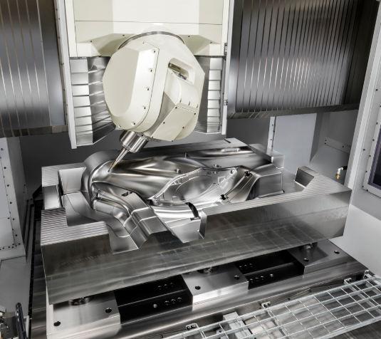
 ผลิตจำนวนน้อย แต่มีมาตรฐานสูง บริการสร้างต้นแบบอย่างรวดเร็วของเรามาพร้อมกับการตรวจสอบที่เร็วขึ้นและง่ายขึ้น —

บริการตัดและดัดโลหะ: เหตุใดการเลือกวัสดุจึงเป็นปัจจัยสำคัญที่ทำให้โครงการของคุณประสบความสำเร็จหรือล้มเหลว
ความเข้าใจเกี่ยวกับการตัดและดัดโลหะในฐานะกระบวนการที่เชื่อมโยงกัน
คุณเคยสงสัยหรือไม่ว่าแผ่นเหล็กเรียบๆ หนึ่งแผ่นสามารถเปลี่ยนรูปเป็นชิ้นส่วนยึดที่มีความแม่นยำสูงซึ่งใช้ยึดระบบช่วงล่างของรถยนต์คุณได้อย่างไร? คำตอบอยู่ที่บริการการตัดและดัดโลหะ — ซึ่งเป็นสองกระบวนการขึ้นรูปที่ทำงานร่วมกันอย่างกลมกลืน เหมือนคู่เต้นรำที่ประสานจังหวะกันอย่างพิถีพิถัน แม้ว่าผู้ผลิตจำนวนมากจะมองว่ากระบวนการเหล่านี้เป็นการดำเนินงานแยกจากกัน แต่การเข้าใจถึงความเชื่อมโยงอย่างลึกซึ้งระหว่างทั้งสองกระบวนการนี้คือกุญแจสำคัญในการบรรลุผลลัพธ์ที่เหนือกว่าในโครงการของคุณ
โดยพื้นฐานแล้ว บริการแบบบูรณาการเหล่านี้เกี่ยวข้องกับการเปลี่ยนแผ่นโลหะดิบให้กลายเป็น ชิ้นส่วนสามมิติที่ใช้งานได้จริง ผ่านลำดับขั้นตอนการผลิตที่ต่อเนื่องกัน การตัดกำหนดรูปร่าง ในขณะที่การดัดให้รูปทรง ทั้งสองกระบวนการนี้จึงพึ่งพาอาศัยกันอย่างแยกไม่ออก — กระบวนการหนึ่งจะไม่ประสบความสำเร็จได้ หากอีกกระบวนการหนึ่งไม่สามารถดำเนินการได้อย่างสมบูรณ์แบบ
จากแผ่นโลหะแบน ไปสู่ชิ้นส่วนสำเร็จรูป
ลองนึกภาพว่าคุณเริ่มต้นด้วยแผ่นอลูมิเนียมหรือเหล็กที่บริสุทธิ์อย่างสมบูรณ์ กระบวนการเปลี่ยนวัตถุดิบไปเป็นชิ้นส่วนสำเร็จรูปนั้นดำเนินตามลำดับขั้นตอนที่คาดการณ์ได้ก่อนอื่นคือขั้นตอนการตัด—ไม่ว่าจะใช้เลเซอร์ พลาสม่า หรือเจ็ทน้ำ—เพื่อสร้างสิ่งที่ผู้ผลิตชิ้นส่วนเรียกว่า "แผ่นต้นแบบ (blank)" ซึ่งเป็นชิ้นงานแบนราบที่มีรูปร่างโดยละเอียดตรงกับชิ้นส่วนสุดท้าย รวมถึงรู ร่อง หรือลักษณะเฉพาะที่ซับซ้อนต่างๆ ด้วย
แต่สิ่งที่ทำให้กระบวนการนี้น่าสนใจยิ่งคือ แผ่นต้นแบบ (blank) นั้นไม่ใช่เพียงแค่รูปร่างหนึ่งรูปเท่านั้น แต่เป็นรูปแบบที่คำนวณมาอย่างรอบคอบ โดยคำนึงถึงการยืดและการหดตัวของวัสดุขณะขึ้นรูปด้วยการพับ ผู้ผลิตชิ้นส่วนที่มีประสบการณ์รู้ดีว่า การพับมุม 90 องศาไม่ได้เป็นเพียงการพับโลหะเท่านั้น แต่ยังเปลี่ยนแปลงมิติของวัสดุตามแนวเส้นพับอีกด้วย นี่จึงเป็นเหตุผลที่ขั้นตอนการตัดและการพับต้องทำงานร่วมกันอย่างกลมกลืน เพื่อให้ได้ผลลัพธ์ที่แม่นยำ
เหตุใดคุณภาพของการตัดจึงกำหนดความสำเร็จของการพับ
จงนึกภาพคุณภาพการตัดว่าเป็นรากฐานของบ้าน หากฐานรากไม่ตรง ทุกสิ่งที่สร้างขึ้นด้านบนก็จะได้รับผลกระทบตามไปด้วย หลักการเดียวกันนี้ก็ใช้ได้กับกรณีนี้เช่นกัน คุณภาพขอบของชิ้นงานที่ได้จากการตัดโดยตรง จะส่งผลต่อความเรียบร้อยและความแม่นยำของการดัดวัสดุ
ขอบที่หยาบหรือได้รับผลกระทบจากความร้อนจากการตัดอาจก่อให้เกิดรอยแตกจุลภาคในระหว่างการดัด ส่งผลให้ชิ้นส่วนมีความแข็งแรงลดลง หรือล้มเหลวอย่างสิ้นเชิง ในทางกลับกัน การตัดที่สะอาดและแม่นยำจะสร้างเส้นแนวการดัดที่สม่ำเสมอ ซึ่งนำไปสู่มุมและขนาดที่ถูกต้องทุกครั้ง
ความเชื่อมโยงนี้อธิบายว่าทำไมบริการเชื่อมแบบมืออาชีพและโรงงานแปรรูปโลหะจึงลงทุนอย่างมากในการบำรุงรักษาอุปกรณ์การตัดของตน เลนส์เลเซอร์ที่สึกหรอหรือปลายพลาสมาที่ทื่น ไม่เพียงแต่ส่งผลต่อคุณภาพการตัดเท่านั้น แต่ยังทำให้การดัดทุกขั้นตอนที่ตามมาสำหรับชิ้นส่วนนั้นเสียประสิทธิภาพด้วย
คำอธิบายลำดับขั้นตอนการแปรรูป
การเข้าใจลำดับขั้นตอนการแปรรูปทั้งหมดจะช่วยให้คุณสื่อสารกับผู้ให้บริการแปรรูปของคุณได้อย่างมีประสิทธิภาพมากยิ่งขึ้น นี่คือลำดับขั้นตอนที่มักเกิดขึ้น:
- การทบทวนการออกแบบ วิศวกรวิเคราะห์รูปทรงชิ้นส่วนของคุณ เพื่อระบุปัญหาที่อาจเกิดขึ้นทั้งในขั้นตอนการตัดและการดัด
- การพัฒนาแบบแบน (Flat pattern development): ซอฟต์แวร์คำนวณรูปร่างของแผ่นวัสดุเริ่มต้น (blank) อย่างแม่นยำ โดยคำนึงถึงค่าการยืดตัวขณะดัด (bend allowances) และพฤติกรรมของวัสดุ
- การดำเนินการตัด: ทำการตัดแผ่นวัสดุเริ่มต้นด้วยวิธีที่เหมาะสมที่สุดสำหรับวัสดุและข้อกำหนดด้านความแม่นยำของคุณ
- ลำดับการดัด (Bending sequence): ดำเนินการดัดหลายครั้งตามลำดับที่กำหนดไว้เป็นพิเศษ เพื่อหลีกเลี่ยงการชนกันของเครื่องมือและรักษาความแม่นยำ
- การตรวจสอบคุณภาพ: ชิ้นส่วนสุดท้ายจะถูกวัดเทียบกับข้อกำหนดทางเทคนิค เพื่อให้มั่นใจว่าทั้งกระบวนการตัดและดัดสามารถบรรลุค่าความคลาดเคลื่อน (tolerances) ที่ต้องการ
ไม่ว่าคุณจะกำลังทำงานร่วมกับผู้ให้บริการงานขึ้นรูปโลหะ Metco หรือกำลังมองหาผู้ให้บริการงานขึ้นรูปโลหะใน Lafayette รัฐอินเดียนา โปรดเลือกคู่ค้าที่เข้าใจความสัมพันธ์แบบบูรณาการนี้อย่างแท้จริง ผู้ให้บริการงานขึ้นรูปโลหะที่ดีที่สุดไม่ได้เสนอเพียงแค่บริการตัดและดัดเป็นรายการแยกในใบเสนอราคาเท่านั้น แต่ยังมองโครงการของคุณเป็นความท้าทายในการผลิตแบบบูรณาการหนึ่งเดียว
ตลอดคู่มือแบบครอบคลุมนี้ คุณจะได้เรียนรู้ว่าเทคนิคการตัดที่แตกต่างกันส่งผลต่อผลลัพธ์ของการดัดอย่างไร ทำไมการเลือกวัสดุจึงมีความสำคัญมากกว่าที่หลายคนคิด และวิธีการออกแบบชิ้นส่วนให้ทั้งใช้งานได้จริงและผลิตได้จริง ถือว่าคู่มือนี้เป็นคู่มืออ้างอิงสำหรับการตัดสินใจอย่างมีข้อมูลในการผลิตชิ้นส่วนครั้งต่อไปของคุณ
วิธีการตัดโลหะและผลกระทบต่อกระบวนการผลิต
การเลือกวิธีการตัดที่ไม่เหมาะสมอาจทำให้คุณสูญเสียเงินหลายพันบาทจากวัสดุที่สูญเปล่าและการทำงานซ้ำ ฟังดูเกินจริงหรือ? แต่นี่คือความจริงที่ผู้ผลิตจำนวนมากต้องเผชิญ เมื่อพวกเขาไม่ได้เลือกเทคโนโลยีการตัดให้สอดคล้องกับความต้องการของโครงการแต่ละโครงการ วิธีการตัดแต่ละแบบสร้างลักษณะขอบที่ไม่เหมือนกัน ซึ่งส่งผลโดยตรงต่อพฤติกรรมของวัสดุในระหว่างกระบวนการดัด ลองมาพิจารณาอย่างละเอียดกัน เทคโนโลยีการตัดหลักสี่แบบ และค้นหาว่าแต่ละแบบเหมาะกับสถานการณ์ใด
การตัดด้วยเลเซอร์เพื่อขอบที่มีความแม่นยำ
การตัดด้วยเลเซอร์ใช้ลำแสงที่มีความเข้มข้นสูงมากในการหลอมวัสดุให้ละลายผ่านไปอย่างแม่นยำเทียบได้กับการผ่าตัด หากโครงการของคุณต้องการขอบที่เรียบเนียน รูขนาดเล็ก หรือรูปร่างที่ซับซ้อน การตัดด้วยเลเซอร์จะให้ผลลัพธ์ที่ยอดเยี่ยม เทคโนโลยีนี้เหมาะอย่างยิ่งสำหรับแผ่นวัสดุบาง โดยทั่วไปสามารถจัดการกับวัสดุที่มีความหนาตั้งแต่ 0.005 นิ้ว ถึง 1.5 นิ้ว ขึ้นอยู่กับกำลังวัตต์ของเลเซอร์
อะไรทำให้การตัดด้วยเลเซอร์มีคุณค่าเป็นพิเศษสำหรับการดัดวัสดุในขั้นตอนถัดไป? ลำแสงที่มีความเข้มข้นสูงสร้างขอบที่เรียบเนียนอย่างน่าทึ่ง ซึ่งต้องการการตกแต่งเพิ่มเติมหลังการตัดน้อยมาก เมื่อคุณดัดชิ้นส่วนที่ตัดด้วยเลเซอร์ คุณจะทำงานกับสมบัติของวัสดุที่สม่ำเสมอตลอดความยาวของขอบทั้งหมด — ไม่มีบริเวณที่หยาบกร้านซึ่งอาจก่อให้เกิดจุดสะสมแรงเครียดหรือรอยร้าวจุลภาคขณะขึ้นรูป
อย่างไรก็ตาม การตัดด้วยเลเซอร์จะสร้างความร้อน ซึ่งก่อให้เกิดสิ่งที่เรียกว่า 'โซนที่ได้รับผลกระทบจากความร้อน' (Heat Affected Zone: HAZ) แม้ว่าโซนนี้จะมีขนาดค่อนข้างเล็กเมื่อเทียบกับวิธีการตัดด้วยความร้อนอื่นๆ แต่ก็อาจเปลี่ยนแปลงคุณสมบัติของวัสดุบริเวณขอบที่ถูกตัดได้เล็กน้อย สำหรับการดัดวัสดุทั่วไปส่วนใหญ่ โซน HAZ ที่มีขนาดเล็กมากนี้ไม่ก่อให้เกิดปัญหาใดๆ แต่สำหรับโลหะผสมที่ไวต่อความร้อน หรือชิ้นส่วนสำคัญในอุตสาหกรรมการบินและอวกาศ คุณควรพิจารณาใช้วิธีการอื่นแทน
การตัดด้วยลำแสงน้ำสำหรับวัสดุที่ไวต่อความร้อน
ลองนึกภาพการตัดเหล็กด้วยน้ำและทรายเพียงอย่างเดียว นั่นคือสิ่งที่ การตัดด้วยเจ็ทน้ำแบบมีสารกัดกร่อน ทำได้จริง โดยใช้น้ำภายใต้แรงดันสูงมาก—โดยทั่วไปอยู่ระหว่าง 60,000 ถึง 90,000 PSI—ผสมกับอนุภาคกัดกร่อน กระบวนการตัดแบบเย็นนี้กำจัดข้อกังวลที่เกี่ยวข้องกับความร้อนทั้งหมด จึงเป็นทางเลือกอันดับหนึ่งเมื่อความสมบูรณ์ของวัสดุเป็นสิ่งสำคัญที่สุด
ตลาดการตัดด้วยเจ็ทน้ำกำลังขยายตัวอย่างรวดเร็ว โดยคาดว่าจะเติบโตจนแตะระดับมากกว่า 2.39 พันล้านดอลลาร์สหรัฐภายในปี ค.ศ. 2034 การเติบโตนี้สะท้อนให้เห็นว่าผู้ผลิตต่างตระหนักถึงข้อได้เปรียบเฉพาะตัวของเทคโนโลยีนี้ ได้แก่
- ไม่มีโซนที่ได้รับผลกระทบจากความร้อน: ไม่มีการบิดงอ ไม่มีการแข็งตัว และไม่มีการบิดเบี้ยวจากความร้อน
- ความหลากหลายของวัสดุ: ตัดวัสดุเกือบทุกชนิดได้ ตั้งแต่เหล็ก หิน ไปจนถึงวัสดุคอมโพสิต
- ความสามารถในการตัดความหนา: สามารถตัดได้สูงสุด 6 นิ้วบนเหล็กกล้าไร้สนิม และ 20 นิ้วบนอลูมิเนียม
- ความสามารถแบบ 5 แกน: สร้างรูปทรงเรขาคณิตที่ซับซ้อนและขอบเอียง (bevels) ด้วยความแม่นยำสูง
สำหรับการดำเนินการดัด ขอบที่ตัดด้วยเครื่องตัดเจ็ทน้ำ (waterjet) จะให้สมบัติของวัสดุที่สม่ำเสมอตลอดแนวขอบตัด โดยไม่มีชั้นวัสดุที่แข็งตัวซึ่งจะขัดขวางกระบวนการดัด และไม่มีแรงดันตกค้างที่ทำให้เกิดการคืนตัว (springback) อย่างไม่สม่ำเสมอ ความสม่ำเสมอนี้ส่งผลให้ผลลัพธ์ของการดัดคาดการณ์ได้แม่นยำยิ่งขึ้น — ซึ่งเป็นข้อได้เปรียบสำคัญสำหรับงานที่ต้องการความแม่นยำสูง
การตัดด้วยพลาสม่าสำหรับวัสดุหนา
เมื่อคุณทำงานกับโลหะนำไฟฟ้าที่มีความหนาและต้องการกระบวนการที่คุ้มค่า วิธีการตัดด้วยพลาสม่าจึงเป็นทางเลือกที่เหนือกว่า เทคโนโลยีนี้ใช้อาร์กไฟฟ้าร่วมกับก๊าซอัดเพื่อสร้างลำพลาสม่าที่มีอุณหภูมิสูงถึง 5,000 องศาเซลเซียส ซึ่งสามารถหลอมละลายและเป่าผ่านเหล็ก อลูมิเนียม และทองแดงได้อย่างรวดเร็ว
การตัดพลาสม่า มีข้อได้เปรียบที่ชัดเจนสำหรับงานแผ่นโลหะหนา:
- สามารถตัดแผ่นเหล็กที่มีความหนาเกิน 1 นิ้ว ซึ่งเลเซอร์มักมีข้อจำกัดในการเจาะผ่าน
- ต้นทุนอุปกรณ์ต่ำกว่า — ประมาณ 90,000 ดอลลาร์สหรัฐ เมื่อเทียบกับระบบน้ำแรงดันสูง (waterjet) แบบเดียวกันที่มีราคาประมาณ 195,000 ดอลลาร์สหรัฐ
- ความเร็วในการประมวลผลวัสดุหนาเร็วกว่า — เร็วขึ้น 3–4 เท่าเมื่อเปรียบเทียบกับระบบน้ำแรงดันสูง (waterjet) ในการตัดเหล็กหนา 1 นิ้ว
- ต้นทุนการดำเนินงานต่อฟุตต่ำกว่าประมาณครึ่งหนึ่งเมื่อเทียบกับระบบน้ำแรงดันสูง (waterjet)
ข้อแลกเปลี่ยนคืออะไร? การตัดด้วยพลาสม่าสร้างโซนที่ได้รับผลกระทบจากความร้อน (heat affected zone) ที่กว้างกว่า ทำให้วัสดุบริเวณขอบแข็งและเปราะกว่า ส่งผลให้เกิดความเอียงเล็กน้อยบนผิวที่ถูกตัด โดยขอบด้านบนมักสะอาดกว่าขอบด้านล่าง สำหรับการดัดชิ้นส่วนโครงสร้างที่มีความหนา ลักษณะเหล่านี้มักมีผลน้อยกว่าเมื่อเทียบกับงานแผ่นโลหะที่ต้องการความแม่นยำสูง อย่างไรก็ตาม ชิ้นส่วนที่ตัดด้วยพลาสม่าอาจจำเป็นต้องผ่านกระบวนการรองเพิ่มเติมก่อนการดัด เพื่อให้มั่นใจในผลลัพธ์ที่สม่ำเสมอ
คุณภาพของขอบส่งผลต่อการดัดชิ้นงานของคุณอย่างไร
นี่คือจุดที่ทฤษฎีพบกับการปฏิบัติจริง ลักษณะของขอบที่ได้จากวิธีการตัดที่คุณเลือกจะส่งผลโดยตรงต่อความแม่นยำของการดัด ความแข็งแรงของชิ้นส่วน และคุณภาพผิวสัมผัส โปรดพิจารณาผลกระทบที่เกิดขึ้นจริงดังต่อไปนี้:
ความหยาบของผิว: ขอบที่หยาบอาจทำให้การสัมผัสกับเครื่องดัดโลหะ (press brake tooling) ไม่สม่ำเสมอ ส่งผลให้มุมการดัดเปลี่ยนแปลงไปตามความยาวของรอยดัด ขอบที่ได้จากเลเซอร์และเจ็ทน้ำให้ความเรียบเนียนสูงสุด ในขณะที่ขอบที่ได้จากการตัดพลาสมาอาจจำเป็นต้องผ่านขั้นตอนเตรียมขอบก่อนดัดสำหรับงานดัดที่มีความสำคัญเป็นพิเศษ
โซนที่ได้รับผลกระทบจากความร้อน: วัสดุที่แข็งตัวบริเวณขอบที่ถูกตัดด้วยความร้อนจะมีพฤติกรรมการดัดที่แตกต่างจากวัสดุต้นฉบับ ส่งผลให้เกิดปรากฏการณ์สปริงแบ็ก (springback) ที่คาดเดาไม่ได้ และอาจเกิดรอยแตกร้าวเมื่อดัดรอบรัศมีเล็กมาก ขอบที่ได้จากการตัดด้วยเจ็ทน้ำแบบเย็น (cold-cut waterjet) จะกำจัดตัวแปรนี้ออกไปได้อย่างสิ้นเชิง
ความตั้งฉากของขอบ ขอบที่เอียง (beveled edges) ที่เกิดจากการตัดพลาสมาอาจทำให้วัสดุเคลื่อนตัวระหว่างกระบวนการดัด ส่งผลให้เกิดข้อผิดพลาดด้านมิติ การตัดด้วยเลเซอร์สามารถรักษาความตั้งฉากของขอบได้ดีเยี่ยมในวัสดุที่มีความหนาเหมาะสม
| วิธี | วัสดุดีที่สุด | ช่วงความหนา | คุณภาพของรอยตัด | โซนที่ได้รับผลกระทบจากความร้อน | ผลกระทบต่อการดัด |
|---|---|---|---|---|---|
| การตัดเลเซอร์ | เหล็กบาง อัลลูมิเนียม สแตนเลส (ชนิดไม่สะท้อนแสง) | 0.005 นิ้ว – 1.5 นิ้ว | ยอดเยี่ยม - ขอบเรียบเนียนและสะอาด | ขนาดเล็ก – เปลี่ยนแปลงวัสดุน้อยมาก | เส้นดัดที่สม่ำเสมอ ไม่จำเป็นต้องเตรียมขอบมากนัก |
| การตัดด้วยน้ำแรงดันสูง | โลหะทุกชนิด คอมโพสิต หิน แก้ว | สูงสุด 6 นิ้ว สำหรับเหล็ก, 20 นิ้ว สำหรับอลูมิเนียม | ดีมาก — เรียบลื่น แต่มีพื้นผิวเล็กน้อย | ไม่มี - กระบวนการตัดแบบเย็น | การคืนตัวของสปริงคาดการณ์ได้แม่นยำที่สุด เหมาะสำหรับโลหะผสมที่ไวต่อความร้อน |
| การตัดพลาสม่า | โลหะนำไฟฟ้า — เหล็ก อลูมิเนียม ทองแดง | 0.5 นิ้ว – 6 นิ้ว (เหมาะที่สุดเมื่อเกิน 0.5 นิ้ว) | ปานกลาง — มีขอบเอียงเล็กน้อย และขอบด้านล่างหยาบกว่า | ขนาดใหญ่ — ก่อให้เกิดโซนที่แข็งและเปราะกว่า | อาจจำเป็นต้องขัดขอบ และการโค้งแบบความแม่นยำสูงคาดการณ์ได้ยากกว่า |
| การเจาะด้วย CNC | อลูมิเนียม พลาสติก และโลหะที่นุ่มกว่า | โดยทั่วไปน้อยกว่า 1 นิ้ว | ดี – ตัดแบบกลไกที่สะอาด | น้อยมาก – เกิดจากความร้อนจากการเสียดสีเท่านั้น | ขอบที่เรียบเนียนเหมาะสำหรับการดัด แต่จำกัดเฉพาะวัสดุที่นุ่มกว่า |
สรุปแล้ว การเลือกวิธีการตัดให้สอดคล้องกับทั้งชนิดวัสดุและข้อกำหนดในการดัดนั้นไม่ใช่ทางเลือก แต่เป็นสิ่งจำเป็นเพื่อให้ได้ผลลัพธ์ที่มีคุณภาพ โรงงานแปรรูปโลหะที่ประสบความสำเร็จหลายแห่งมักใช้เทคโนโลยีการตัดหลายแบบ และเลือกวิธีที่เหมาะสมที่สุดสำหรับความต้องการเฉพาะของแต่ละโครงการ เมื่อคุณพิจารณาโครงการถัดไป โปรดจำไว้ว่า การตัดที่คุณเลือกวันนี้จะกำหนดคุณภาพของการดัดที่คุณจะได้ในวันพรุ่งนี้
เทคนิคการดัดโลหะที่จำเป็น พร้อมคำอธิบาย
คุณได้เลือกวิธีการตัดที่เหมาะสมและผลิตชิ้นงานเปล่าที่เรียบเนียนแล้ว ตอนนี้มาถึงขั้นตอนการเปลี่ยนรูป — นำโลหะแผ่นแบนมาขึ้นรูปให้กลายเป็นชิ้นส่วนที่ใช้งานได้จริง แต่สิ่งที่ทำให้ผู้แปรรูปโลหะระดับเฉลี่ยแตกต่างจากผู้เชี่ยวชาญระดับยอดเยี่ยมคือ ความเข้าใจว่าวิธีการดัดแบบใดเหมาะสมกับความต้องการเฉพาะของคุณที่สุด ลองมาสำรวจวิธีหลักทั้งหกแบบที่ บริการตัดและดัดโลหะมืออาชีพ ใช้งานเป็นประจำทุกวัน
การดัดแบบแอร์เบนดิ้งเทียบกับการดัดแบบบอททอมเบนดิ้ง
เทคนิคทั้งสองนี้คิดเป็นสัดส่วนประมาณ 90% ของการดัดทั้งหมด แต่ให้ผลลัพธ์ที่แตกต่างกันอย่างมาก การเข้าใจความแตกต่างระหว่างทั้งสองวิธีจะช่วยให้คุณระบุแนวทางที่เหมาะสมสำหรับโครงการของคุณได้
การขบอากาศ ทำงานตามหลักการที่เรียบง่ายอย่างสวยงาม หัวดัดจะเคลื่อนที่ลงสู่แม่พิมพ์รูปตัววี (V-die) แต่วัสดุจะไม่สัมผัสกับพื้นผิวด้านล่างของแม่พิมพ์เลย มีเพียงจุดสัมผัสสามจุดเท่านั้น ได้แก่ ปลายหัวดัด และขอบทั้งสองข้างของช่องเปิดแม่พิมพ์ มุมการดัดจะถูกกำหนดโดยระยะที่หัวดัดเคลื่อนที่ลงไปในแม่พิมพ์เท่านั้น — ไม่ได้ขึ้นอยู่กับรูปทรงเรขาคณิตของอุปกรณ์ดัด
- ต้องการแรงดันต่ำ: ใช้หลักการคานแทนแรงดันโดยตรง จึงต้องการแรงดันน้อยมากเมื่อเทียบกับวิธีอื่น
- ความยืดหยุ่นสูงสุด: ชุดอุปกรณ์ดัดเพียงชุดเดียวสามารถผลิตมุมใดก็ได้ในช่วง 90 ถึง 180 องศา
- ลดการลงทุนด้านอุปกรณ์ดัด: ไม่จำเป็นต้องใช้หัวดัดและแม่พิมพ์ที่ออกแบบเฉพาะสำหรับมุมต่าง ๆ
- การคืนตัวของวัสดุ (Springback): วัสดุจะคืนตัวหลังจากปล่อยแรงดัน จึงจำเป็นต้องดัดเกินมุมเป้าหมายเพื่อให้ได้มุมที่ต้องการ
- ค่าความคลาดเคลื่อนทั่วไป: ± 0.5 ถึง 1 องศา สำหรับความแม่นยำของมุมภายใต้สภาวะมาตรฐาน
การขบด้านล่าง (เรียกอีกอย่างว่าการกดที่สุด) ช่วยยกระดับความแม่นยำขึ้นอีกขั้น ลูกสูบจะกดวัสดุแน่นเข้ากับพื้นผิวของแม่พิมพ์ ทำให้วัสดุมีรูปร่างใกล้เคียงกับเรขาคณิตของเครื่องมือมากยิ่งขึ้น แม้ว่าปรากฏการณ์สปริงแบ็ก (springback) จะยังคงเกิดขึ้น แต่ลดลงอย่างมีนัยสำคัญเมื่อเทียบกับการดัดแบบอากาศ (air bending)
- ความแม่นยำที่สูงขึ้น: ให้ความแม่นยำของมุมที่แคบกว่าการดัดแบบอากาศ
- แรงกดระดับปานกลาง: ต้องใช้แรงมากกว่าการดัดแบบอากาศ 2–3 เท่า
- ควบคุมสปริงแบ็กได้: โดยทั่วไปจะใช้เครื่องมือที่มีมุมแหลมกว่า (เช่น มุม 88 องศา) เพื่อให้วัสดุสปริงแบ็กกลับมาเป็นมุมที่ต้องการคือ 90 องศา
- การควบคุมรัศมีด้านในของการโค้ง: ความกว้างของช่อง V ของแม่พิมพ์กำหนดรัศมีด้านในของการโค้ง — โดยประมาณเท่ากับ V/6
- การใช้งานที่เหมาะสมที่สุด: การผลิตในปริมาณปานกลางที่ต้องการมุมที่สม่ำเสมอและสามารถทำซ้ำได้
เมื่อใดที่การดัดแบบโคอินนิ่ง (coining) เหมาะสม
ลองนึกภาพดูว่า คุณใช้แรงกดมากจนโครงสร้างภายในของโลหะถูกจัดเรียงใหม่ทั้งหมดอย่างแท้จริง นี่คือกระบวนการ 'โคอินนิง' (coining) — ซึ่งให้ความแม่นยำที่วิธีการอื่นไม่สามารถเทียบเคียงได้เลย
เทคนิคนี้ได้ชื่อมาจากวิธีการผลิตเหรียญในสมัยโบราณ ซึ่งโลหะจะถูกกดลงในแม่พิมพ์ด้วยแรงสูงพอที่จะถ่ายทอดรายละเอียดทุกส่วนออกมาได้อย่างสมบูรณ์แบบ ปัจจุบัน กระบวนการโคอินนิงด้วยเครื่องดัดแผ่นโลหะ (press brake) ใช้หลักการเดียวกันนี้ โดยใช้แรงกดสูงกว่าการดัดแบบอากาศ (air bending) ถึง 5–10 เท่า เพื่อบังคับให้วัสดุเข้าไปเต็มบริเวณโพรงของแม่พิมพ์อย่างสมบูรณ์
นี่คือสิ่งที่เกิดขึ้นในระดับโมเลกุลระหว่างกระบวนการโคอินนิง: หัวดัด (punch) ไม่เพียงแต่ดัดวัสดุเท่านั้น แต่ยังเจาะลึกลงไปและบีบอัดแกนกลาง (neutral axis) ทำลายสมดุลของแรงเครียดที่เป็นสาเหตุของปรากฏการณ์สปริงแบ็ก (springback) ผลลัพธ์ที่ได้คือ มุมของแม่พิมพ์จะกลายเป็นมุมของชิ้นงานอย่างแน่นอน
- ความแม่นยําที่พิเศษ บรรลุความคลาดเคลื่อนได้ดีกว่า ± 0.1 องศา
- ไม่มีการเด้งกลับหลังขึ้นรูป (Zero Springback): ความจำเชิงยืดหยุ่น (elastic memory) ของวัสดุถูกกำจัดออกไปโดยแท้จริง
- ความสม่ำเสมอในการผลิต: ชิ้นส่วนทุกชิ้นตรงกับรูปร่างของแม่พิมพ์อย่างแม่นยำ
- รัศมีด้านในที่เล็ก: สร้างมุมที่คมชัดและมีนิยามชัดเจน ซึ่งเป็นสิ่งที่วิธีการอื่นไม่สามารถทำได้
- ข้อแลกเปลี่ยน: ต้องใช้เครื่องมือเฉพาะทาง อุปกรณ์กำลังสูง และทำให้วัสดุบางลงบริเวณจุดโค้ง
การขึ้นรูปแบบโคอินนิง (coining) จะคุ้มค่ากับต้นทุนเพิ่มเติมเมื่อใด? ควรพิจารณาใช้สำหรับชิ้นส่วนยานยนต์ที่เกี่ยวข้องกับความปลอดภัยอย่างยิ่ง ชิ้นส่วนอากาศยานที่ต้องรับแรงซ้ำๆ ผลิตภัณฑ์ทางการแพทย์ที่ต้องการรูปทรงเรขาคณิตที่สมบูรณ์แบบ และการผลิตจำนวนมากที่การกำจัดความแปรปรวนจะช่วยป้องกันปัญหาในการประกอบขั้นตอนถัดไป
การดัดโค้งสำหรับชิ้นส่วนที่มีรูปทรงโค้ง
ไม่ใช่ทุกจุดโค้งที่จำเป็นต้องมีมุมแหลม เมื่อการออกแบบของคุณต้องการเส้นโค้ง โค้งรูปส่วนโค้ง หรือทรงกระบอกสมบูรณ์ กระบวนการดัดแบบโรลเบนดิ้ง (roll bending) จะให้ผลลัพธ์ที่เครื่องดัดโลหะแบบกด (press brake) ทำไม่ได้
โดยทั่วไป กระบวนการนี้ใช้ลูกกลิ้งปรับระดับได้สามตัว จัดเรียงในรูปแบบพีระมิดหรือแบบหนีบ (pinch configuration) เมื่อวัสดุผ่านเข้าไป วัสดุจะค่อยๆ เกิดความโค้งตามตำแหน่งของลูกกลิ้ง วิธีการนี้เหมาะอย่างยิ่งสำหรับการผลิต:
- เส้นโค้งรัศมีใหญ่สำหรับองค์ประกอบทางสถาปัตยกรรม
- ส่วนทรงกระบอกสำหรับถังและภาชนะรับแรงดัน
- รูปทรงกรวยสำหรับไซโล (hoppers) และชิ้นส่วนเชื่อมต่อ (transitions)
- รูปแบบเกลียว (spiral forms) สำหรับระบบลำเลียง
การดัดแบบโรลสามารถจัดการกับความหนาของวัสดุตั้งแต่แผ่นบางไปจนถึงแผ่นหนัก โดยอุปกรณ์บางชนิดสามารถขึ้นรูปเหล็กที่มีความหนาเกิน 6 นิ้วได้ การขึ้นรูปแบบค่อยเป็นค่อยไปนี้ก่อให้เกิดการแข็งตัวจากการขึ้นรูป (work hardening) น้อยมาก เมื่อเทียบกับการดัดแบบคมชัด จึงช่วยรักษาความเหนียวของวัสดุไว้สำหรับกระบวนการต่อเนื่อง
ข้อพิจารณาที่สำคัญประการหนึ่ง: การดัดแบบโรลมักทิ้งส่วนที่เรียบ (flat sections) ไว้ที่ขอบด้านหน้าและด้านหลังของวัสดุ ซึ่ง 'จุดเรียบ' เหล่านี้เกิดขึ้นเพราะลูกกลิ้งไม่สามารถสัมผัสกับส่วนปลายของวัสดุได้อย่างสมบูรณ์ ดังนั้นการออกแบบควรคำนึงถึงข้อจำกัดนี้ หรือระบุให้มีการดำเนินการเพิ่มเติม (secondary operations) เพื่อให้การโค้งสมบูรณ์
อธิบายการปฏิบัติงานของเครื่องดัดโลหะแบบกด (Press Brake)
เครื่องดัดโลหะแบบกดยังคงเป็นเครื่องจักรหลักในการให้บริการดัดโลหะ ซึ่งสามารถดำเนินการดัดแบบอากาศ (air bending), ดัดแบบรองรับพื้น (bottoming) และดัดแบบกดแน่น (coining) ได้ ขึ้นอยู่กับการตั้งค่าและการใช้แรงที่เหมาะสม การเข้าใจศักยภาพของเครื่องดัดโลหะแบบกดจะช่วยให้คุณสื่อสารความคาดหวังที่สมจริงกับพันธมิตรด้านการผลิตของคุณ
เครื่องดัดโลหะแบบกดควบคุมด้วยระบบ CNC รุ่นใหม่สามารถบรรลุข้อกำหนดทางเทคนิคที่น่าประทับใจเมื่อมีการบำรุงรักษาและปฏิบัติงานอย่างเหมาะสม:
- ช่วงมุม: 1 ถึง 135 องศา (และมากกว่านั้นด้วยเครื่องมือพิเศษ)
- ความแม่นยำของมุม: ความคลาดเคลื่อน ±1 องศาตามมาตรฐาน หรือ ±0.25 องศาด้วยอุปกรณ์ระดับพรีเมียม
- ความคลาดเคลื่อนของความยาว: ความคลาดเคลื่อน ±0.015 นิ้ว สำหรับมิติที่ผ่านการขึ้นรูปแล้ว
- ความสามารถในการทำซ้ำ: ความคลาดเคลื่อน ±0.0004 นิ้ว สำหรับตำแหน่งของลูกสูบ
- แรงสูงสุด: สูงสุดถึง 1,000 ตัน บนอุปกรณ์ขนาดใหญ่
- ความยาวในการดัด: สูงสุดถึง 7,200 มิลลิเมตร (ประมาณ 24 ฟุต)
ปัจจัยใดบ้างที่ส่งผลต่อความสามารถในการบรรลุค่าความคลาดเคลื่อนเหล่านี้? ความสม่ำเสมอของวัสดุเป็นปัจจัยอันดับหนึ่ง ตาม แนวทางการกำหนดค่าความคลาดเคลื่อนของอุตสาหกรรม แม้แต่ในเกรดวัสดุเดียวกัน ความแปรผันระหว่างล็อตในการผลิต เช่น ความหนา (+/- 0.05 มม.) หรือความแข็งแรงดึง ก็ส่งผลให้พฤติกรรมการดัดเปลี่ยนแปลงอย่างมีนัยสำคัญ ปัจจัยสำคัญอื่นๆ ได้แก่
สภาพเครื่องจักร: ความขนานระหว่างลูกสูบกับฐานเครื่องต้องรักษาไว้ภายในค่า 0.01 มม. แม้ความเบี่ยงเบนเพียงเล็กน้อยก็ส่งผลให้เกิดข้อผิดพลาดของมุมที่สังเกตเห็นได้ชัดภายใต้แรงกดหลายร้อยตัน
การเลือกเครื่องมือ ความกว้างของช่องเปิดแม่พิมพ์กำหนดรัศมีด้านใน (โดยประมาณ V/6) ส่วนปลายของหัวดัดที่สึกกร่อนจะทำให้รัศมีที่ได้ไม่สม่ำเสมอตลอดความยาวของการดัด
ความเชี่ยวชาญของผู้ปฏิบัติงาน: แม้ระบบควบคุมด้วย CNC จะมีความแม่นยำ ผู้ปฏิบัติงานที่มีประสบการณ์ยังสามารถสังเกตรูปแบบพฤติกรรมของวัสดุและปรับพารามิเตอร์ต่างๆ ให้เหมาะสมตามนั้น
สภาพแวดล้อม การเปลี่ยนแปลงของอุณหภูมิส่งผลต่อความหนืดของของเหลวไฮดรอลิกและคุณสมบัติของวัสดุ ซึ่งก่อให้เกิดความแปรผันเล็กน้อยในสภาพแวดล้อมการผลิต
การดัดแบบโรตารีสมควรได้รับการกล่าวถึงในฐานะเทคนิคเฉพาะสำหรับเครื่องดัดโลหะ (press brake) โดยใช้แม่พิมพ์แบบหมุนแทนการเคลื่อนที่เชิงเส้นของลูกสูบ ซึ่งการดัดแบบโรตารีสามารถสร้างมุมแหลมคมได้โดยไม่ทำให้ผิววัสดุเกิดรอยขีดข่วน — ซึ่งเป็นสิ่งสำคัญยิ่งสำหรับชิ้นงานโลหะในงานสถาปัตยกรรมที่มองเห็นได้ชัด หรือวัสดุที่ผ่านการตกแต่งพื้นผิวมาแล้ว นอกจากนี้ยังสามารถดัดมุมที่แหลมกว่า 90 องศาได้ในครั้งเดียว จึงหลีกเลี่ยงปัญหาการคืนตัว (springback) ที่มักเกิดขึ้นได้สำหรับความต้องการมุมทั่วไป
การเข้าใจหลักการพื้นฐานของการดัดเหล่านี้จะช่วยให้คุณตัดสินใจอย่างชาญฉลาดยิ่งขึ้นเกี่ยวกับโครงการผลิตชิ้นส่วนของคุณ อย่างไรก็ตาม การเลือกเทคนิคเพียงอย่างเดียวยังไม่ครอบคลุมเรื่องทั้งหมด ทางเลือกของวัสดุที่ใช้มีอิทธิพลอย่างมากต่อวิธีการที่เหมาะสมที่สุด และผลลัพธ์ที่คุณคาดหวังได้จริง — ซึ่งเป็นหัวข้อที่ควรพิจารณาอย่างรอบคอบ
การเลือกวัสดุสำหรับโครงการตัดและดัด
เคยสั่งอาหารจากร้านอาหารเครือข่ายหนึ่งด้วยความคาดหวังว่าจะได้รสชาติที่สม่ำเสมอ แต่กลับพบว่าวัตถุดิบสำคัญกว่าสูตรการทำหรือไม่? หลักการเดียวกันนี้ก็ใช้ได้กับงานขึ้นรูปโลหะเช่นกัน คุณอาจเลือกวิธีการตัดที่เหมาะสมที่สุดและเทคนิคการดัดที่ดีที่สุด แต่หากคุณเลือกวัสดุผิดชนิด หรือไม่คำนึงถึงพฤติกรรมเฉพาะตัวของวัสดุนั้น โครงการของคุณก็จะล้มเหลว — อย่างแท้จริง
โลหะแต่ละกลุ่มมีลักษณะเฉพาะที่ส่งผลต่อกระบวนการตัดและการดัดอย่างชัดเจน อลูมิเนียมสามารถดัดได้ง่าย แต่มีแนวโน้มที่จะคืนตัวกลับ (springback) อย่างไม่แน่นอน เหล็กให้ความแข็งแรงสูง แต่ต้องใช้แรงมากกว่า ส่วนสแตนเลสสตีลรวมเอาความท้าทายของทั้งสองชนิดเข้าด้วยกัน พร้อมเพิ่มความซับซ้อนเฉพาะตัวอีกด้วย การเข้าใจความแตกต่างเหล่านี้จะเปลี่ยนคุณจากผู้ที่แค่สั่งชิ้นส่วน ไปเป็นผู้ที่ออกแบบเพื่อความสำเร็จ
ความท้าทายและแนวทางแก้ไขในการดัดอลูมิเนียม
อลูมิเนียมดูเหมือนจะเป็นวัสดุที่เหมาะที่สุดสำหรับงานขึ้นรูป — เบา ทนต่อการกัดกร่อน และหาได้ง่าย แต่ช่างขึ้นรูปที่มีประสบการณ์รู้ดีว่ามันแฝงความลับอันน่าหงุดหงิดไว้: พฤติกรรมการคืนตัวกลับอย่างมีนัยสำคัญ ที่อาจทำให้งานความแม่นยำผิดพลาด
เมื่อคุณดัดอลูมิเนียม ผิวด้านนอกจะยืดออก ในขณะที่ผิวด้านในจะหดตัว ระหว่างสองบริเวณนี้คือแกนกลาง (neutral axis) ซึ่งเป็นส่วนของวัสดุที่ได้รับแรงเครียดต่ำที่สุด หลังจากปล่อยแรงดัดออก ชั้นผิวด้านนอกที่ถูกยืดออกจะพยายามหดกลับ ส่วนชั้นผิวด้านในที่ถูกบีบอัดจะพยายามขยายตัว ผลลัพธ์ที่ได้คือ มุมดัด 90 องศาของคุณอาจคลายตัวเป็น 92 หรือ 93 องศา
โลหะผสมอลูมิเนียมแต่ละชนิดมีคุณสมบัติในการขึ้นรูปที่แตกต่างกันอย่างมาก:
- อลูมิเนียม 5052: มีความสามารถในการขึ้นรูปได้ดีเยี่ยม พร้อมทั้งทนต่อการกัดกร่อนได้ดี — เป็นตัวเลือกแรกสำหรับงานแผ่นโลหะทั่วไปที่ต้องการการดัดในระดับปานกลาง
- อลูมิเนียม 5083: มีความแข็งแรงสูงสุดในหมู่โลหะผสมอลูมิเนียมที่ไม่ผ่านการอบความร้อนเพื่อเพิ่มความแข็ง แต่ไม่แนะนำให้ใช้งานที่อุณหภูมิเกิน 65°C
- อะลูมิเนียม 6061: ผ่านกระบวนการตกตะกอนเพื่อเพิ่มความแข็ง (Precipitation-hardened) และมีคุณสมบัติเชิงกลที่ดี อย่างไรก็ตาม จำเป็นต้องใช้รัศมีการดัดที่ใหญ่กว่าเพื่อป้องกันการแตกร้าว
- 7075 อลูมิเนียม: มีอัตราส่วนความแข็งแรงต่อน้ำหนักที่โดดเด่น แต่ยากต่อการขึ้นรูป — มักจำเป็นต้องผ่านการรักษาความร้อนก่อนการดัด
ทางออกคืออะไร? การดัดเกินมุมที่ต้องการ (Overbending) ผู้ผลิตชิ้นส่วนจะดัดอลูมิเนียมให้เลยมุมเป้าหมายโดยเจตนา เพื่อให้แรงคืนตัว (springback) ทำให้วัสดุคลายตัวกลับมาอยู่ในตำแหน่งที่ต้องการอย่างแม่นยำ ปริมาณการดัดเกินมุมที่แน่นอนนั้นขึ้นอยู่กับองค์ประกอบของโลหะผสม (alloy), สถานะการอบร้อน (temper), ความหนาของวัสดุ และรัศมีการดัด (bend radius) — ซึ่งเป็นตัวแปรที่โรงงานที่มีประสบการณ์กำหนดผ่านการทดสอบหรือข้อมูลประวัติศาสตร์
เกรดเหล็กและคุณสมบัติในการขึ้นรูป
เหล็กยังคงเป็นโครงสร้างหลักของการผลิตอุตสาหกรรม เนื่องจากมีพฤติกรรมที่คาดการณ์ได้ดีกว่าอลูมิเนียมอย่างชัดเจน ปัจจัยแรงคืนตัวที่ต่ำกว่าและลักษณะการขึ้นรูปที่สม่ำเสมอทำให้เหล็กเป็นตัวเลือกอันดับหนึ่งเมื่อความแม่นยำของมิติเป็นสิ่งสำคัญ
ปริมาณคาร์บอนมีอิทธิพลอย่างมากต่อคุณสมบัติในการขึ้นรูป ตัวอย่างเช่น เหล็กคาร์บอนต่ำอย่าง DC01 (เหล็กแผ่นรีดเย็น คาร์บอนต่ำ) สามารถดัดได้ง่ายและเชื่อมได้ดี ความเหนียวของวัสดุชนิดนี้ช่วยให้สามารถดัดด้วยรัศมีเล็กๆ ได้โดยไม่เกิดรอยแตกร้าว อย่างไรก็ตาม เมื่อปริมาณคาร์บอนเพิ่มขึ้น ความแข็งแรงก็เพิ่มขึ้น แต่ความสามารถในการขึ้นรูปก็ลดลง — ซึ่งเป็นการแลกเปลี่ยนที่นักออกแบบทุกคนจำเป็นต้องพิจารณาอย่างรอบคอบ
เกรดเหล็กที่ใช้บ่อยสำหรับการตัดและการดัด ได้แก่:
- S235JR: เหล็กโครงสร้างรีดร้อนที่มีความสามารถในการเชื่อมได้ดีเยี่ยมและมีความเหนียวดี เหมาะสำหรับงานขึ้นรูปทั่วไป
- DC01: เหล็กรีดเย็นที่มีปริมาณคาร์บอนต่ำมาก มีความเหนียวสูงมาก และเหมาะอย่างยิ่งสำหรับการขึ้นรูปที่ซับซ้อน
- S355J2: เหล็กโครงสร้างที่มีความแข็งแรงสูงกว่า ออกแบบมาเพื่อใช้กับชิ้นส่วนที่ต้องรับแรงเครียดอย่างมีนัยสำคัญ แม้จะต้องใช้รัศมีการดัดที่ใหญ่กว่า
- C45 (1045): เหล็กกล้าคาร์บอนระดับกลาง ให้คุณสมบัติต้านทานการสึกหรอและความแข็งแรง แต่มีความเหนียวลดลง จึงจำกัดความสามารถในการดัดแบบแน่น
ข้อได้เปรียบของเหล็กยังขยายไปถึงกระบวนการตัดด้วย ไม่ว่าจะเป็นการตัดด้วยเลเซอร์ซึ่งให้ขอบที่เรียบสะอาดและมีโซนที่ได้รับผลกระทบจากความร้อนน้อยมากบนเหล็กกล้าคาร์บอนต่ำ หรือการตัดด้วยพลาสมาซึ่งสามารถตัดแผ่นโครงสร้างหนาได้อย่างมีประสิทธิภาพในเชิงต้นทุน ลักษณะการตัดที่คาดการณ์ได้เช่นนี้ส่งผลโดยตรงต่อผลลัพธ์ของการดัดที่สม่ำเสมอ
ปัจจัยการคืนตัวของสปริงสแตนเลส
สแตนเลสสตีลผสมผสานคุณสมบัติในการต้านทานการกัดกร่อนเข้ากับความสวยงาม และแสดงพฤติกรรมการคืนตัว (springback) ที่ท้าทายที่สุดเมื่อเปรียบเทียบกับวัสดุที่ใช้ในการผลิตทั่วไป โมดูลัสของความยืดหยุ่นที่สูงกว่าหมายความว่ามีพลังงานยืดหยุ่นสะสมมากขึ้นระหว่างการดัด ส่งผลให้เกิดการคืนตัวกลับมากขึ้นเมื่อแรงกดถูกปล่อยออก
เกรดออสเทนิติก (ซีรีส์ 300) เป็นที่นิยมใช้มากที่สุดในการผลิต:
- สเตนเลสเกรด 304: เกรดมาตรฐานที่มีคุณสมบัติต้านทานการกัดกร่อนได้ดีเยี่ยม สามารถกลึงได้ง่าย และขึ้นรูปได้สะดวก แม้ว่าพฤติกรรมการคืนตัวจะสูงกว่าเหล็กกล้าคาร์บอนต่ำโดยทั่วไปถึง 30–50%
- สเตนเลสเกรด 316: การเติมโมลิบดีนัมช่วยเพิ่มความสามารถในการต้านทานคลอไรด์ จึงเหมาะอย่างยิ่งสำหรับการใช้งานในสภาพแวดล้อมทางทะเลและอุตสาหกรรมเคมี โดยมีคุณสมบัติการขึ้นรูปใกล้เคียงกับเกรด 304
การชดเชยพฤติกรรมการคืนตัวของสแตนเลสสตีลจำเป็นต้องใช้การดัดเกินเป้าหมายอย่างรุนแรงยิ่งขึ้น — บางครั้งอาจต้องดัดเกินมุมเป้าหมายถึง 3–5 องศา เครื่องดัดแบบ CNC ขั้นสูงที่ติดตั้งเซ็นเซอร์วัดมุมและระบบดัดแบบปรับตัวได้ จะวัดมุมการดัดจริงแบบเรียลไทม์ และปรับค่าโดยอัตโนมัติเพื่อให้บรรลุผลตามที่กำหนดไว้ แม้จะมีความแปรผันของวัสดุ
การดัดที่อุณหภูมิห้องยังทำให้เหล็กกล้าไร้สนิมเกิดการแข็งตัวจากการขึ้นรูป (work-hardening) ซึ่งส่งผลให้การดัดครั้งต่อไปทำได้ยากขึ้น ผู้ผลิตจึงวางแผนลำดับการดัดอย่างรอบคอบ โดยดำเนินการดัดมุมที่สำคัญก่อนที่วัสดุจะแข็งตัวจนเกินไปจนไม่สามารถขึ้นรูปได้อย่างแม่นยำ
ขีดจำกัดความหนาสำหรับวัสดุแต่ละชนิด
ความหนาของวัสดุกำหนดขอบเขตสำหรับทั้งกระบวนการตัดและการดัด แผ่นวัสดุที่หนากว่าจำเป็นต้องใช้รัศมีการดัดที่ใหญ่ขึ้นเพื่อหลีกเลี่ยงการแตกร้าว — ความสัมพันธ์นี้ขึ้นอยู่กับความสามารถในการดัดตัว (ductility) ของวัสดุและแรงเครียดที่เกิดขึ้นระหว่างการขึ้นรูป
ตามแนวทางการกำหนดรัศมีการดัด รัศมีการดัดขั้นต่ำมักสัมพันธ์กับความหนาและชนิดของวัสดุ โดยทั่วไปแล้ว วัสดุที่นุ่มกว่าสามารถรองรับรัศมีการดัดที่แคบกว่า ในขณะที่วัสดุที่แข็งกว่าต้องการเส้นโค้งที่ค่อยเป็นค่อยไปมากกว่า การพยายามดัดเกินขีดจำกัดเหล่านี้จะทำให้เกิดรอยแตกร้าวที่ผิวด้านนอกของการดัด — ซึ่งเป็นความเสียหายที่ไม่สามารถซ่อมแซมได้
ความหนายังส่งผลต่อขนาดช่องเปิดของแม่พิมพ์รูปตัววี (V-die opening) ที่ใช้ในการดัด แผ่นวัสดุที่หนากว่าจำเป็นต้องใช้ช่องเปิดของแม่พิมพ์ที่ใหญ่ขึ้นเพื่อ:
- รองรับการไหลของวัสดุโดยไม่ทำให้เกิดรอยขีดข่วนหรือรอยขูดบนพื้นผิว
- ป้องกันความต้องการแรงที่มากเกินไป ซึ่งอาจทำให้แม่พิมพ์เสียหาย
- บรรลุรัศมีโค้งด้านในที่เหมาะสม (ประมาณหนึ่งในหกของความกว้างช่องเปิด V)
| ประเภทวัสดุ | ปัจจัยการเด้งกลับ | รัศมีการงอต่ำสุด | วิธีการตัดที่แนะนำ | ข้อควรพิจารณาเป็นพิเศษ |
|---|---|---|---|---|
| อลูมิเนียม (5052) | สูง (โดยทั่วไป 2–4 องศา) | 1.0 เท่าของความหนา | เลเซอร์หรือเจ็ทน้ำ (ไม่มีข้อกังวลเรื่องโซนที่ได้รับความร้อนจากกระบวนการตัด) | วัสดุที่มีความแข็งน้อยกว่าสามารถดัดได้ง่ายกว่า; หลีกเลี่ยงมุมแหลมเมื่อดัดวัสดุที่มีความแข็งสูง |
| อลูมิเนียม (6061-T6) | สูง (โดยทั่วไป 3–5 องศา) | อย่างน้อย 2.0 เท่าของความหนา | แนะนำให้ใช้เครื่องตัดด้วยน้ำแรงสูง (Waterjet) สำหรับชิ้นงานที่มีความหนา | การอบชุบด้วยความร้อนส่งผลต่อความสามารถในการขึ้นรูป อาจจำเป็นต้องอบอ่อนก่อนดัดงอ |
| เหล็กกล้าอ่อน (A36/S235) | ต่ำ (โดยทั่วไปอยู่ที่ 0.5–1.5 องศา) | 0.5 เท่าของความหนา | ใช้เลเซอร์สำหรับวัสดุบาง และพลาสม่าสำหรับแผ่นโลหะหนา | มีพฤติกรรมการขึ้นรูปที่คาดการณ์ได้แม่นยำที่สุด; เหมาะอย่างยิ่งสำหรับการพัฒนาต้นแบบ |
| สแตนเลส (304) | ปานกลางถึงสูง (โดยทั่วไปอยู่ที่ 2–3 องศา) | 1.0 เท่าของความหนา | ใช้เลเซอร์หรือเครื่องตัดด้วยน้ำแรงสูง (Waterjet) (หลีกเลี่ยงการใช้พลาสม่าเนื่องจากอาจทำให้เกิดคราบเปลี่ยนสี) | วัสดุเกิดการแข็งตัวจากการทำงาน (Work hardens) ระหว่างการขึ้นรูป; จึงควรวางแผนลำดับการดัดอย่างรอบคอบ |
| สแตนเลสสตีล (316) | ปานกลางถึงสูง (โดยทั่วไปอยู่ที่ 2–3 องศา) | 1.0 เท่าของความหนา | เครื่องตัดด้วยน้ำแรงสูงสำหรับชิ้นงานที่มีความหนา; เลเซอร์สำหรับชิ้นงานที่บาง | ต้องใช้แรงขึ้นรูปที่สูงกว่า; เหมาะอย่างยิ่งสำหรับสภาพแวดล้อมที่กัดกร่อน |
การเปรียบเทียบวัสดุนี้เผยให้เห็นว่าทำไมผู้ผลิตที่มีประสบการณ์จึงขอระบุเกรดโลหะผสมเฉพาะแทนที่จะใช้ชื่อวัสดุทั่วไป การแตกต่างกันระหว่างอลูมิเนียมเกรด 5052 กับ 6061 หรือระหว่างสแตนเลสเกรด 304 กับ 316 ส่งผลโดยตรงต่อค่าความคลาดเคลื่อนที่สามารถทำได้ ความต้องการแม่พิมพ์ และต้นทุนโครงการ
การเลือกวัสดุของคุณส่งผลกระทบต่อการตัดสินใจทุกขั้นตอนที่ตามมา โดยกำหนดว่าวิธีการตัดแบบใดจะให้ขอบที่ดีที่สุด ปริมาณการโค้งเกิน (overbending) ที่จำเป็นเพื่อชดเชยปรากฏการณ์ springback และแม้แต่ความเป็นไปได้ในการบรรลุค่าความคลาดเคลื่อนตามที่ออกแบบไว้ เมื่อคุณเข้าใจประเด็นเหล่านี้อย่างลึกซึ้งแล้ว คุณก็พร้อมที่จะรับมือกับความท้าทายอีกประการหนึ่งที่มักถูกมองข้าม: การวางแผนลำดับของการดัดหลายครั้งโดยไม่สร้างรูปทรงเรขาคณิตที่เป็นไปไม่ได้
ข้อพิจารณาด้านการออกแบบและกลยุทธ์การจัดลำดับการดัด
ลองนึกภาพนี้ดู: คุณได้ออกแบบแบร็กเก็ตที่สวยงามซึ่งมีรอยพับที่แม่นยำสี่จุด วัสดุที่ใช้เหมาะสมอย่างยิ่ง ค่าความคลาดเคลื่อน (tolerances) แคบมาก และผู้ผลิตชิ้นส่วนของคุณก็มีอุปกรณ์ระดับพรีเมียม แต่เมื่อเริ่มการผลิต รอยพับจุดที่สามกลับกลายเป็นไปไม่ได้ในทางกายภาพ เนื่องจากขอบที่ถูกพับแล้วชนเข้ากับเครื่องพับโลหะ (press brake tooling) ทำให้โครงการของคุณต้องหยุดชะงักทันที
สถานการณ์เช่นนี้เกิดขึ้นบ่อยกว่าที่ผู้ผลิตจะยอมรับ สาเหตุหลักคือ การจัดลำดับการพับที่ไม่เหมาะสม และการออกแบบที่ไม่เอื้อต่อการผลิต (design for manufacturability) แม้ว่าการตัดจะสร้างแผ่นวัตถุดิบ (blank) ขึ้นมา และคุณสมบัติของวัสดุจะกำหนดปริมาณการคืนตัวหลังพับ (springback) แต่ สั่งซื้อ ลำดับที่รอยพับแต่ละจุดเกิดขึ้นนั้น คือปัจจัยที่กำหนดว่าชิ้นส่วนของคุณจะสามารถผลิตได้จริงหรือไม่
การวางแผนลำดับการพับ
ให้คุณมองการจัดลำดับการพับเหมือนการแก้ปริศนาแบบย้อนกลับทีละขั้นตอน แต่ละรอยพับจะเปลี่ยนแผ่นวัตถุดิบที่แบนราบให้กลายเป็นรูปทรงสามมิติมากขึ้นเรื่อย ๆ — และมีข้อจำกัดในการทำงานเพิ่มขึ้นตามลำดับ หลักสำคัญคือ การคาดการณ์ล่วงหน้าว่าแต่ละรอยพับจะส่งผลต่อเรขาคณิตของชิ้นงานอย่างไร ซึ่งจะส่งผลต่อพื้นที่ที่เหลือสำหรับการดำเนินการในขั้นตอนถัดไป
เมื่อวางแผนชิ้นส่วนที่มีการดัดหลายจุด ให้ปฏิบัติตามแนวทางเชิงระบบดังนี้:
- ระบุตำแหน่งของการดัดทั้งหมดลงบนแบบแผ่นเรียบ (flat pattern) ของคุณ: กำหนดหมายเลขแต่ละจุดที่ดัด และบันทึกทิศทางของการดัด (ขึ้นหรือลง) มุมที่ดัด และระยะห่างจากฟีเจอร์อื่นๆ
- ระบุโซนที่อาจเกิดการขัดขวางกัน: หลังจากการดัดแต่ละจุดที่เสนอไว้ ให้จินตนาการว่าขอบที่ถูกขึ้นรูปจะอยู่ในตำแหน่งใดเมื่อเทียบกับลูกแม่พิมพ์ (punch), แม่พิมพ์ (die) และโครงเครื่องจักร
- ทำงานจากด้านในออกสู่ด้านนอก: โดยทั่วไป ควรดำเนินการดัดบริเวณที่อยู่ใกล้ศูนย์กลางของชิ้นงานก่อน จากนั้นจึงค่อยๆ ขยายออกไปภายนอก — วิธีนี้จะช่วยให้ขอบที่ขึ้นรูปแล้วไม่ไปขัดขวางกับอุปกรณ์ขึ้นรูป
- พิจารณาการสลับทิศทางของการดัด: การสลับระหว่างการดัดแบบขึ้นกับการดัดแบบลงมักให้ระยะปลอดภัยที่ดีกว่าการดัดต่อเนื่องในทิศทางเดียวกัน
- เก็บขอบที่ยาวไว้ทำเป็นลำดับสุดท้าย: แผ่นยื่นที่ขยายออกมามีโอกาสเกิดการชนกันสูงที่สุด — การขึ้นรูปแผ่นยื่นเหล่านี้ในขั้นตอนสุดท้ายจะช่วยลดการรบกวนระหว่างเครื่องมือให้น้อยที่สุด
- ตรวจสอบระยะว่างที่แต่ละขั้นตอน: ใช้การจำลองด้วยซอฟต์แวร์ CAD หรือแบบจำลองจริงเพื่อยืนยันว่าทุกการโค้งงอตามลำดับที่วางแผนไว้นั้นสามารถทำได้จริงทางกายภาพ
ตัวอย่างเชิงปฏิบัติ: จินตนาการถึงชิ้นส่วนรูปตัวยูแบบง่ายๆ ที่มีแผ่นยื่นกลับ (return flanges) ทั้งสองด้าน หากคุณโค้งงอแผ่นยื่นกลับก่อน ด้านข้างของชิ้นส่วนรูปตัวยูจะไม่สามารถขึ้นรูปได้ — เพราะด้านข้างเหล่านั้นจะต้องเคลื่อนผ่านแผ่นยื่นกลับที่ขึ้นรูปเสร็จแล้ว แต่หากเปลี่ยนลำดับการขึ้นรูปใหม่ โดยขึ้นรูปชิ้นส่วนรูปตัวยูก่อน แล้วจึงเพิ่มแผ่นยื่นกลับตามมา กระบวนการผลิตก็จะดำเนินไปอย่างราบรื่น
การหลีกเลี่ยงปัญหาการรบกวนของเครื่องมือ
ตาม แนวทางการออกแบบเพื่อความสะดวกในการผลิต การชนกันเป็นหนึ่งในความล้มเหลวของการขึ้นรูปด้วยการดัดที่พบบ่อยที่สุด ซึ่งเกิดขึ้นได้ในสองรูปแบบที่แตกต่างกัน และการเข้าใจทั้งสองรูปแบบนี้จะช่วยให้คุณออกแบบเพื่อหลีกเลี่ยงปัญหานี้ได้
การชนกันของเครื่องจักร เกิดขึ้นเมื่อรูปทรงของชิ้นส่วนของคุณเข้าไปขัดขวางเครื่องดัดโลหะโดยตรง ตัวอย่างเช่น ฟลานจ์ที่ยาวเกินไปกระทบกับลูกแม่พิมพ์ ช่องแคบเกินไปที่ทำให้เกิดการติดกับแผ่นปรับตำแหน่งด้านหลัง หรือส่วนที่ถูกดัดแล้วชนกับโครงเครื่อง — ทั้งหมดนี้จะหยุดการผลิตทันที สาเหตุทั่วไป ได้แก่
- ฟลานจ์ที่มีความยาวเกินความลึกของช่องปากเครื่อง (ระยะทางจากเส้นดัดถึงโครงเครื่อง)
- ช่องที่แคบเกินไปสำหรับชุดแม่พิมพ์มาตรฐานในการเข้าถึง
- รูปทรงเรขาคณิตที่ซับซ้อนซึ่งจำเป็นต้องให้ชิ้นส่วนยึดครองพื้นที่ที่เครื่องใช้งานอยู่แล้ว
การชนกันเอง เกิดขึ้นเมื่อส่วนต่าง ๆ ของชิ้นส่วนของคุณเข้าไปขัดขวางกันเองระหว่างกระบวนการดัด เช่น กล่องที่มีฟลานจ์หันเข้าหากันอาจต้องให้ฟลานจ์หนึ่งเคลื่อนผ่านอีกฟลานจ์หนึ่งในระหว่างการขึ้นรูป — ซึ่งเป็นไปไม่ได้ทางกายภาพหากไม่มีการปรับแบบใหม่ โปรดสังเกตสิ่งต่อไปนี้:
- รูปทรงเรขาคณิตแบบปิดล้อมที่ทำให้แม่พิมพ์ติดอยู่ภายในชิ้นส่วน
- การดัดแบบย้อนกลับที่ขัดขวางการเข้าถึงสำหรับการดำเนินการขั้นตอนต่อไป
- คุณลักษณะการดัดหลายจุดที่ซับซ้อน ซึ่งส่วนที่ถูกดัดแล้วเข้าไปยึดครองพื้นที่เดียวกัน
วิธีแก้ปัญหามักเกี่ยวข้องกับการปรับความยาวของฟลานจ์ การใช้เครื่องมือพิเศษที่มีความกว้างแคบ หรือการออกแบบชิ้นส่วนใหม่ให้เป็นหลายส่วนที่ประกอบเข้าด้วยกันหลังจากการขึ้นรูป ผู้รับจ้างงานด้านการผลิตชิ้นส่วนของคุณสามารถให้คำแนะนำเกี่ยวกับข้อจำกัดเฉพาะของอุปกรณ์ที่พวกเขาใช้ในระหว่างการทบทวนแบบแปลน
ลักษณะการออกแบบที่ช่วยลดต้นทุน
การตัดสินใจออกแบบอย่างชาญฉลาดตั้งแต่ระยะเริ่มต้นของการพัฒนาจะส่งผลดีต่อทั้งกระบวนการผลิต หลักการเหล่านี้ซึ่งสืบเนื่องมาจาก แนวทางปฏิบัติที่ดีที่สุดในการออกแบบชิ้นส่วนโลหะแผ่น ช่วยให้คุณสร้างชิ้นส่วนที่ทั้งใช้งานได้จริงและผลิตได้อย่างคุ้มค่า
มาตรฐานรัศมีการพับ: การใช้รัศมีด้านในที่สม่ำเสมอทั่วทั้งชิ้นส่วนจะทำให้ผู้ผลิตสามารถขึ้นรูปการโค้งทั้งหมดด้วยการตั้งค่าแม่พิมพ์เพียงครั้งเดียว ทุกครั้งที่มีการเปลี่ยนรัศมี จะต้องมีการเปลี่ยนเครื่องมือ ซึ่งใช้เวลาและเพิ่มต้นทุนโดยไม่เพิ่มมูลค่าใดๆ
รวมช่องคลายแรงขณะโค้งให้เพียงพอ: เมื่อการโค้งตัดกับขอบหรือลักษณะอื่นๆ รอยตัดคลายแรงขนาดเล็กจะช่วยป้องกันไม่ให้วัสดุฉีกขาดหรือบิดเบี้ยว ช่องคลายแรงขณะโค้งมักยื่นเลยเส้นโค้งออกไปเล็กน้อย และมีความกว้างไม่น้อยกว่าความหนาของวัสดุ
รักษาความยาวของฟลานจ์ขั้นต่ำ: แต่ละชุดวัสดุและขนาดความหนาจะมีข้อกำหนดขั้นต่ำสำหรับความยาวของฟลานจ์ — ซึ่งคือระยะทางที่จำเป็นเพื่อให้แม่พิมพ์สามารถรองรับวัสดุได้อย่างเหมาะสม ตัวอย่างเช่น เหล็กสแตนเลสหนา 0.250 นิ้ว ต้องการฟลานจ์อย่างน้อย 1.150 นิ้ว ในขณะที่อลูมิเนียมหนา 0.040 นิ้วต้องการเพียง 0.255 นิ้ว
จัดตำแหน่งรูให้อยู่ห่างจากโซนการดัด: องค์ประกอบที่วางใกล้เส้นดัดเกินไปจะบิดเบี้ยวระหว่างกระบวนการขึ้นรูป ขอบเขตของการบิดเบี้ยวจะแตกต่างกันไปตามชนิดของวัสดุ แต่การเว้นระยะรูให้ห่างจากเส้นดัดอย่างน้อย 2–3 เท่าของความหนาของวัสดุ จะช่วยป้องกันปัญหาการติดขัดของเกลียวและการยึดแน่น
ข้อผิดพลาดทั่วไปในการออกแบบชิ้นส่วนที่ผ่านการดัด
แม้แต่นักออกแบบที่มีประสบการณ์ก็อาจมองข้ามรายละเอียดสำคัญได้เป็นครั้งคราว ตามผลการวิเคราะห์ข้อผิดพลาดทั่วไปในการดัด ข้อผิดพลาดเหล่านี้มักปรากฏซ้ำๆ ทั่วทุกอุตสาหกรรม:
ไม่มีหรือมีร่องลดแรงดัดไม่เพียงพอ: หากไม่มีร่องลดแรงดัดที่เหมาะสมบริเวณจุดตัดของแนวการดัด วัสดุจะรวมตัวกันและฉีกขาด ส่งผลให้เกิดความเข้มข้นของแรงดันสูง รอยร้าวจุลภาคที่ขยายตัวตามเวลา และชิ้นส่วนล้มเหลวก่อนกำหนดภายใต้ภาระ
การคำนวณค่าเบี่ยงเบนของรอยพับผิดพลาด: ซอฟต์แวร์ CAD ของคุณจะคำนวณมิติของรูปแบบแบนโดยอิงจากค่า K-factor และรัศมีของรอยพับที่ป้อนเข้าไป หากค่าเหล่านี้ไม่สอดคล้องกับเครื่องมือจริงที่ผู้ผลิตชิ้นส่วนใช้งาน ชิ้นส่วนที่ผลิตเสร็จแล้วจะไม่ตรงกับแบบจำลองของคุณ ดังนั้น ควรตรวจสอบการตั้งค่าของคุณให้สอดคล้องกับข้อกำหนดเฉพาะของการดัดของโรงงานผู้ผลิตเสมอ
ปีกยื่นที่รองรับไม่เพียงพอ: ปีกยื่นที่มีขอบไม่สม่ำเสมอหรือเส้นรอยพับไม่ขนานกัน จะขาดการรองรับอย่างสม่ำเสมอในระหว่างกระบวนการขึ้นรูป หากไม่มีการสัมผัสอย่างสม่ำเสมอกับแม่พิมพ์ รอยพับที่ได้จะไม่สม่ำเสมอ — มุมของรอยพับจะเปลี่ยนแปลงไปตามความยาวของรอยพับ ซึ่งก่อให้เกิดปัญหาในการประกอบ วิธีแก้ไขคือ การเพิ่มขอบอ้างอิงชั่วคราวที่ให้การรองรับระหว่างการดัด จากนั้นจึงตัดออกภายหลังหากจำเป็น
การเพิกเฉยต่อโซนการบิดเบือน: ทุกการโค้งงอจะสร้างโซนของการเปลี่ยนรูปซึ่งขยายออกไปไกลกว่ารัศมีการโค้งงอที่มองเห็นได้ รู ช่องเปิด และลักษณะอื่นๆ ที่อยู่ภายในโซนนี้จะยืดออก เคลื่อนที่ หรือกลายเป็นรูปไข่ วัสดุแต่ละชนิดมีโซนการบิดเบือนที่แตกต่างกัน — จึงจำเป็นต้องปรึกษาคู่มือเฉพาะวัสดุก่อนตัดสินใจจัดวางลักษณะต่างๆ อย่างสุดท้าย
การออกแบบโดยไม่รับคำแนะนำจากฝ่ายการผลิต: ข้อผิดพลาดที่มีราคาแพงที่สุดคือการดำเนินการออกแบบแบบละเอียดให้เสร็จสมบูรณ์ก่อนปรึกษาพันธมิตรด้านการผลิตของคุณ ซอฟต์แวร์ CAD สมัยใหม่สามารถสร้างรูปทรงเรขาคณิตที่ดูสมบูรณ์แบบบนหน้าจอ แต่กลับเป็นไปไม่ได้ในการขึ้นรูปด้วยเครื่องกด (brake) การร่วมมือกันตั้งแต่เนิ่นๆ จะช่วยระบุปัญหาต่างๆ ได้ในขณะที่ยังไม่มีค่าใช้จ่ายใดๆ สำหรับการปรับเปลี่ยน
การสร้างต้นแบบยังคงเป็นวิธีป้องกันที่ดีที่สุดต่อข้อผิดพลาดเหล่านี้ การผลิตและทดสอบชิ้นส่วนต้นแบบจะเผยให้เห็นปัญหาที่การจำลองแบบไม่สามารถตรวจจับได้ — และมีค่าใช้จ่ายน้อยกว่ามากเมื่อเทียบกับการพบปัญหาในระหว่างการผลิตจริง โปรดรวมขั้นตอนการสร้างต้นแบบไว้ในแผนเวลาและงบประมาณของโครงการ โดยถือว่าเป็นการประกันภัยเพื่อป้องกันการปรับแก้ที่มีค่าใช้จ่ายสูง
เมื่อได้ครอบคลุมหัวข้อการจัดลำดับขั้นตอนการดัดและหลักการออกแบบแล้ว ยังคงมีคำถามสำคัญหนึ่งข้อที่ต้องพิจารณา: ตัวเลือกเหล่านี้ส่งผลต่างบประมาณของโครงการคุณอย่างไร? การเข้าใจปัจจัยต้นทุนในการขึ้นรูปโลหะจะช่วยให้คุณตัดสินใจเลือกทางเลือกที่เหมาะสมระหว่างคุณภาพ ความเร็ว และการลงทุน
ปัจจัยต้นทุนที่มีผลต่อการเลือกวิธีการขึ้นรูปโลหะ
อะไรคือสิ่งที่ทำให้โครงการขึ้นรูปโลหะราคา 500 ดอลลาร์สหรัฐแตกต่างจากโครงการราคา 5,000 ดอลลาร์สหรัฐ? โดยทั่วไปแล้ว สาเหตุไม่ใช่ความซับซ้อนของแบบออกแบบ หรือแม้แต่การเลือกวัสดุ — แต่เป็นความเข้าใจในตัวแปรที่ส่งผลต่อต้นทุน และการตัดสินใจเชิงกลยุทธ์ตั้งแต่เนิ่นๆ อย่างไรก็ตาม บริการตัดและดัดโลหะส่วนใหญ่มักให้ใบเสนอราคาโดยไม่ชี้แจงปัจจัยพื้นฐานที่เกี่ยวข้อง ทำให้คุณต้องคาดเดาเองว่าเหตุใดราคาจึงแตกต่างกันอย่างมากระหว่างผู้ให้บริการแต่ละราย
ความจริงก็คือ ราคาในการขึ้นรูปโลหะขึ้นอยู่กับตัวแปรหลายประการที่เชื่อมโยงกันอย่างซับซ้อน และการรู้ว่าคุณสามารถควบคุมตัวแปรใดได้บ้าง จะเปลี่ยนคุณจากผู้ซื้อแบบพาสซีฟให้กลายเป็นคู่ค้าที่มีความรู้ความเข้าใจอย่างแท้จริง ดังนั้น มาพิจารณาปัจจัยหลักที่ส่งผลต่อต้นทุนโดยละเอียด เพื่อให้คุณสามารถปรับปรุงประสิทธิภาพของโครงการได้อย่างเหมาะสม โดยไม่ต้องเสียสละคุณภาพ
พิจารณาปริมาณในการเลือกวิธีการผลิต
นี่คือความจริงที่ดูขัดแย้งกันในครั้งแรก: วิธีการผลิตที่ถูกที่สุดสำหรับชิ้นส่วน 10 ชิ้น อาจกลายเป็นวิธีที่แพงที่สุดสำหรับชิ้นส่วน 10,000 ชิ้น ปริมาณการผลิตมีผลโดยพื้นฐานต่อการเลือกวิธีการผลิตที่ให้ประสิทธิภาพทางเศรษฐกิจสูงสุด
ต้นทุนการเตรียมเครื่องจักร (Setup costs) ถือเป็นปัจจัยที่ทำให้ต้นทุนเท่าเทียมกัน ไม่ว่าจะเป็นการเขียนโปรแกรมเครื่อง CNC การจัดตั้งอุปกรณ์เครื่องมือ หรือการตรวจสอบชิ้นงานต้นแบบ (first-article inspection) — ต้นทุนคงที่เหล่านี้มีอยู่ไม่ว่าคุณจะผลิตชิ้นส่วนเพียงหนึ่งชิ้นหรือหนึ่งพันชิ้นก็ตาม ตามการวิเคราะห์ต้นทุนของอุตสาหกรรม การตัดด้วยเลเซอร์หรือพลาสม่าโดยทั่วไปมีค่าใช้จ่าย $1.50–$6.00 ต่อฟุตเชิงเส้นของความยาวที่ตัด ส่วนการดัดพื้นฐานมีค่าใช้จ่าย $1–$5 ต่อการดัดหนึ่งครั้ง แต่ตัวเลขเหล่านี้บอกเพียงบางส่วนของเรื่องราวทั้งหมด
พิจารณาการแยกประเภทต้นทุนตามปริมาณการผลิตต่อไปนี้:
- ต้นแบบ (1–10 หน่วย): ต้นทุนการเตรียมเครื่องจักรมีน้ำหนักมากที่สุด ทำให้ราคาต่อชิ้นสูงมากไม่ว่าวิธีการผลิตใดก็ตาม การตัดด้วยเลเซอร์และการดัดแบบอากาศ (air bending) ให้ความยืดหยุ่นสูงโดยไม่จำเป็นต้องลงทุนในแม่พิมพ์
- ปริมาณต่ำ (10–100 หน่วย): ต้นทุนการเตรียมเครื่องจักรยังคงมีน้ำหนักมาก แต่กระจายไปบนจำนวนชิ้นส่วนที่มากขึ้น การเลือกวิธีการผลิตควรเน้นที่ความเร็วและความแม่นยำเป็นหลัก มากกว่าการปรับแต่งให้ได้ราคาต่อหน่วยต่ำที่สุด
- ปริมาณปานกลาง (100–1,000 หน่วย): ประสิทธิภาพการผลิตเริ่มมีความหมาย การลงทุนเพื่อเพิ่มประสิทธิภาพกระบวนการ — เช่น ใช้อุปกรณ์ยึดชิ้นงานเฉพาะทาง หรือปรับรูปแบบการจัดวางวัสดุให้เหมาะสมที่สุด — เริ่มคืนทุน
- ปริมาณสูง (มากกว่า 1,000 หน่วย): ต้นทุนต่อชิ้นเป็นปัจจัยหลัก แม่พิมพ์ขึ้นรูปที่มีราคาต้นทุนเริ่มต้น 5,000–50,000 ดอลลาร์สหรัฐ อาจลดต้นทุนต่อชิ้นจาก 5 ดอลลาร์สหรัฐ ลงเหลือเพียง 0.50 ดอลลาร์สหรัฐ ซึ่งสร้างการประหยัดอย่างมหาศาลตลอดระยะเวลาการผลิต
บทเรียนที่ได้? เลือกวิธีการให้สอดคล้องกับปริมาณการผลิตของคุณ เช่นเดียวกับนักเดินทางที่เปรียบเทียบตัวเลือกโรงแรมระดับมอเติลในโคโค่บีชกับโรงแรมหรูตามความต้องการและงบประมาณของตน ผู้ซื้อชิ้นส่วนสำเร็จรูปก็ควรประเมินวิธีการผลิตแต่ละแบบตามความต้องการเฉพาะด้านการผลิตของตน แทนที่จะสมมุติว่าวิธีใดวิธีหนึ่งเหมาะกับทุกสถานการณ์
เมื่อความละเอียดแม่นยำสูงขึ้น ส่งผลให้ต้นทุนเพิ่มขึ้น
ความแม่นยำมาพร้อมราคา — แต่การเข้าใจเหตุผลที่แท้จริงจะช่วยให้คุณระบุข้อกำหนดเฉพาะที่จำเป็นจริง ๆ เท่านั้น ตาม การศึกษาผลกระทบของความคลาดเคลื่อนที่ยอมรับได้ ข้อกำหนดที่เข้มงวดเกินไปส่งผลให้ต้นทุนเพิ่มขึ้นผ่านหลายกลไก:
ข้อกำหนดของอุปกรณ์: เครื่องดัดโลหะแบบ CNC มาตรฐานสามารถบรรลุความแม่นยำเชิงมุมได้ที่ ±1 องศา แต่หากต้องการความแม่นยำสูงขึ้นถึง ±0.25 องศา จะต้องใช้อุปกรณ์ระดับพรีเมียมที่มีระบบวัดมุมแบบเรียลไทม์และระบบดัดแบบปรับตัวได้ — ซึ่งเป็นเครื่องจักรที่มีอัตราค่าบริการต่อชั่วโมงสูงกว่า
ความเร็วในการประมวลผล: ความคลาดเคลื่อนที่แคบลงหมายถึงการดำเนินงานที่ช้าลง ผู้ปฏิบัติงานจำเป็นต้องตรวจสอบขนาดอย่างสม่ำเสมอมากขึ้น ทำการปรับค่าทีละน้อย และบางครั้งอาจต้องผ่านกระบวนการขึ้นรูปหลายรอบ งานที่ใช้เวลาเพียงหนึ่งนาทีภายใต้ความคลาดเคลื่อนมาตรฐาน อาจใช้เวลารวมสามนาทีเมื่อต้องการความแม่นยำสูง
ภาระงานด้านการตรวจสอบ: ทุกมิติที่กำหนดความคลาดเคลื่อนแบบแคบจะต้องได้รับการตรวจสอบยืนยัน ซึ่งรวมถึงเวลาที่ใช้กับเครื่องวัดพิกัด (CMM), เครื่องวัดเฉพาะทาง และเอกสารประกอบโดยละเอียด ทั้งหมดนี้เป็นต้นทุนเพิ่มเติมที่ชิ้นส่วนมาตรฐานไม่ต้องรับผิดชอบ
อัตราของเสีย: ยิ่งช่วงความคลาดเคลื่อนของคุณแคบลงเท่าใด จำนวนชิ้นส่วนที่ไม่เป็นไปตามข้อกำหนดก็จะยิ่งเพิ่มขึ้นเท่านั้น ตัวอย่างเช่น ข้อกำหนดความคลาดเคลื่อน ±0.030 นิ้ว อาจให้ผลชิ้นส่วนที่ยอมรับได้ 98% แต่หากเพิ่มความเข้มงวดเป็น ±0.010 นิ้ว อัตรานี้อาจลดลงเหลือเพียง 90% ซึ่งเท่ากับว่าต้นทุนต่อชิ้นเพิ่มขึ้นจริงประมาณ 8–10%
แนวทางอัจฉริยะคืออะไร? ระบุว่ามิติใดบ้างมีความสำคัญต่อการใช้งานอย่างแท้จริง และกำหนดค่าความคลาดเคลื่อนที่แคบเฉพาะในส่วนนั้นเท่านั้น พื้นผิวที่สัมผัสกัน (mating surfaces), จุดเชื่อมต่อสำหรับการประกอบ (assembly interfaces) และลักษณะเฉพาะที่เกี่ยวข้องกับความปลอดภัย (safety-critical features) จำเป็นต้องได้รับความแม่นยำสูง แต่สำหรับมิติภายนอกของแผ่นฝาครอบตกแต่ง (decorative cover plate) ค่าความคลาดเคลื่อนมาตรฐานมักเพียงพอ และงบประมาณของคุณจะขอบคุณคุณ
การสมดุลระหว่างคุณภาพและงบประมาณ
ทุกการตัดสินใจเกี่ยวกับกระบวนการผลิตมีองค์ประกอบของการแลกเปลี่ยนเสมอ หัวใจสำคัญคือการตัดสินใจอย่างมีสติ ไม่ใช่ทำไปตามค่าเริ่มต้น โปรดพิจารณาสถานการณ์ทั่วไปต่อไปนี้:
เกรดวัสดุเทียบกับสมรรถนะ: สแตนเลสสตีลเกรด 304 มีราคาสูงกว่าเหล็กกล้าคาร์บอนต่ำ (mild steel) ประมาณ 30% แต่ให้คุณสมบัติในการต้านทานการกัดกร่อนที่อาจช่วยตัดค่าใช้จ่ายด้านการตกแต่งออกได้ ดังนั้นควรดำเนินการวิเคราะห์ต้นทุนแบบครบวงจร ไม่ใช่เพียงพิจารณาจากราคาวัตถุดิบเท่านั้น
ข้อแลกเปลี่ยนระหว่างวิธีการตัด: การตัดด้วยเจ็ทน้ำ (waterjet cutting) สามารถกำจัดโซนที่ได้รับผลกระทบจากความร้อน (heat-affected zones: HAZ) ได้ แต่มีต้นทุนสูงกว่าการตัดด้วยพลาสมา (plasma) ประมาณสองเท่าต่อฟุต สำหรับเหล็กโครงสร้างที่มีความหนาซึ่งโซน HAZ ไม่ส่งผลต่อการใช้งาน การตัดด้วยพลาสมาย่อมเหมาะสมกว่า แต่สำหรับชิ้นส่วนอากาศยานที่ต้องการความแม่นยำสูง การลงทุนเพิ่มเติมสำหรับการตัดด้วยเจ็ทน้ำจะคุ้มค่า เนื่องจากช่วยลดขั้นตอนการปรับแต่งหลังการตัด (post-processing)
การเลือกวิธีการดัด: การดัดด้วยอากาศ (Air bending) ใช้แรงกดน้อยกว่าและช่วยให้สามารถปรับเปลี่ยนเครื่องมือได้อย่างยืดหยุ่น แต่ส่งผลให้มุมที่ได้มีความแปรผันกว้างขึ้น ในขณะที่การดัดแบบโคอินนิง (Coining) ให้ความแม่นยำสูงมาก แต่ต้องใช้แรงกดมากกว่า 5–10 เท่า และต้องใช้เครื่องมือเฉพาะทาง ดังนั้นควรเลือกวิธีการให้สอดคล้องกับความต้องการด้านความแม่นยำที่แท้จริงของคุณ
การจัดทำกรอบการตัดสินใจจะช่วยให้คุณสามารถประเมินทางเลือกเหล่านี้ได้อย่างมีประสิทธิภาพ โปรดถามตัวเองว่า:
- ข้อกำหนดขั้นต่ำสุดที่จำเป็นสำหรับชิ้นส่วนชิ้นนี้เพื่อให้สามารถทำงานได้ตามหน้าที่คืออะไร?
- ข้อกำหนดใดบ้างที่เกี่ยวข้องโดยตรงกับความปลอดภัยหรือสมรรถนะที่สำคัญยิ่ง?
- บริเวณใดบ้างที่ฉันสามารถยอมรับค่าความคลาดเคลื่อนที่กว้างขึ้นได้ โดยไม่ส่งผลกระทบต่อผู้ใช้ปลายทาง?
- หากเลือกวิธีการผลิตหลักที่แตกต่างออกไป จะสามารถตัดขั้นตอนการผลิตรอง (secondary operations) ใดออกได้บ้าง?
ค่าใช้จ่ายที่ซ่อนอยู่ซึ่งควรพิจารณา
ใบเสนอราคาที่คุณได้รับมักไม่ครอบคลุมต้นทุนโครงการทั้งหมด ผู้ซื้อที่มีประสบการณ์จะคำนึงถึงค่าใช้จ่ายเหล่านี้ซึ่งมักถูกมองข้ามบ่อยครั้ง:
- การออกแบบและวิศวกรรม: ชิ้นส่วนที่มีความซับซ้อนสูงจำเป็นต้องมีการพัฒนาแบบ CAD การคำนวณรูปแบบแบน (flat pattern) และการทบทวนการออกแบบเพื่อการผลิต (DFM reviews) ตามการวิเคราะห์สัดส่วนต้นทุนการผลิต งานก่อนการผลิตนี้อาจเพิ่มต้นทุนโครงการได้ถึง 10–20%
- การสร้างต้นแบบและการทดสอบ การตรวจสอบชิ้นงานครั้งแรก การตรวจสอบมิติ และการทดสอบการทำงาน ถือเป็นการลงทุนที่ช่วยป้องกันปัญหาการผลิตที่มีค่าใช้จ่ายสูง
- กระบวนการทำงานเพิ่มเติม: การขจัดเศษโลหะ (Deburring) การแทรกชิ้นส่วนยึดตรึง (hardware insertion) การเชื่อม (welding) และการตกแต่งผิว (surface finishing) มักทำให้ต้นทุนของการตัดและดัดพื้นฐานเพิ่มขึ้นเป็นสองเท่า
- ใบรับรองคุณภาพ: การปฏิบัติตามมาตรฐาน ISO 9001 การติดตามแหล่งที่มาของวัสดุ (material traceability) และรายงานการตรวจสอบโดยละเอียด จำเป็นต้องมีกระบวนการที่จัดทำเอกสารอย่างเป็นทางการ ซึ่งส่งผลให้เกิดค่าใช้จ่ายในการบริหารจัดการเพิ่มขึ้น
- ข้อกำหนดด้านการตกแต่งผิว: การเคลือบผง (Powder coating) มีราคาอยู่ที่ 2–5 ดอลลาร์สหรัฐต่อตารางฟุต; ส่วนการชุบแบบพิเศษ (specialized plating) อาจมีราคาสูงถึง 15 ดอลลาร์สหรัฐต่อตารางฟุตขึ้นไป โปรดรวมค่าใช้จ่ายเหล่านี้ไว้ในงบประมาณของท่านตั้งแต่เริ่มต้น
- การบรรจุและการขนส่ง: บรรจุภัณฑ์แบบเฉพาะสำหรับชิ้นส่วนที่บอบบาง สารเคลือบป้องกันสำหรับการเก็บรักษานาน และค่าขนส่งสินค้าไปยังโรงงานของท่าน — ล้วนเป็นค่าใช้จ่ายจริงที่ส่งผลต่อต้นทุนรวมเมื่อสินค้าเข้ามาถึง (total landed cost)
- ค่าเร่งดำเนินการ: คำสั่งซื้อแบบเร่งด่วน (Rush orders) จะรบกวนการวางแผนการผลิต และมักมีค่าธรรมเนียมเพิ่มเติม 25–50% โปรดวางแผนกำหนดเวลาอย่างสมเหตุสมผล เพื่อหลีกเลี่ยงค่าธรรมเนียมเพิ่มเติมเหล่านี้
การค้นคว้าข้อมูลเกี่ยวกับโมเทลในย่านโคโค่บีชก็คล้ายคลึงกับการประเมินใบเสนอราคาสำหรับงานขึ้นรูป กล่าวคือ ต้องพิจารณาปัจจัยอื่นๆ นอกเหนือจากราคาคืนละเพียงอย่างเดียว เช่น สิ่งอำนวยความสะดวก ทำเลที่ตั้ง และค่าใช้จ่ายแฝง ขณะที่การประเมินใบเสนอราคาสำหรับงานขึ้นรูปนั้น ก็จำเป็นต้องพิจารณารายการค่าใช้จ่ายทั้งหมดโดยรวม ไม่ใช่เพียงแค่ราคาแต่ละรายการเท่านั้น
อีกประเด็นหนึ่งที่ควรพิจารณาเป็นอย่างยิ่ง: ใบเสนอราคาที่มีราคาถูกที่สุดไม่ได้หมายความว่าจะให้คุณค่าสูงสุดเสมอไป ผู้ให้บริการขึ้นรูปที่สามารถตรวจพบปัญหาด้านการออกแบบได้ตั้งแต่เนิ่นๆ แนะนำทางเลือกที่ช่วยลดต้นทุน และส่งมอบชิ้นส่วนที่ประกอบเข้าด้วยกันได้อย่างถูกต้องตั้งแต่ครั้งแรก จะสร้างคุณค่าที่ส่งผลลึกซึ้งกว่ามูลค่ารวมบนใบแจ้งหนี้อย่างมาก เมื่อเข้าใจปัจจัยด้านต้นทุนทั้งหมดแล้ว คุณก็พร้อมที่จะสำรวจว่าบริการเหล่านี้มอบคุณค่าเชิงกลยุทธ์ที่สำคัญเพียงใดในแอปพลิเคชันที่มีความต้องการสูง — โดยเริ่มต้นจากอุตสาหกรรมยานยนต์และการผลิตแบบแม่นยำ
การประยุกต์ใช้งานในอุตสาหกรรมยานยนต์และการผลิตชิ้นส่วนความแม่นยำสูง
เมื่อคุณค้นหาพิซซ่าโดมิโนส์ใกล้ตัวคุณผ่านสมาร์ทโฟน คุณคาดหวังความสม่ำเสมอ — ทุกสาขาจะส่งมอบคุณภาพเดียวกันที่คุณไว้วางใจมาโดยตลอด ผู้ผลิตรถยนต์กำหนดมาตรฐานที่เข้มงวดยิ่งกว่านั้นสำหรับผู้จัดจำหน่ายของตน ตัวยึดโครงแชสซีที่ล้มเหลวไม่ใช่เพียงความไม่สะดวกเท่านั้น แต่เป็นภัยพิบัติด้านความปลอดภัยอย่างแท้จริง นี่คือจุดที่บริการตัดและดัดโลหะแสดงศักยภาพของตนเองในแอปพลิเคชันที่ท้าทายที่สุดเท่าที่จินตนาการได้
อุตสาหกรรมยานยนต์ถือเป็นสนามทดสอบขั้นสูงสุดสำหรับความเป็นเลิศในการผลิตชิ้นส่วน ชิ้นส่วนต่าง ๆ ต้องสามารถทนต่ออุณหภูมิสุดขั้ว การสั่นสะเทือนอย่างต่อเนื่อง สภาพถนนที่กัดกร่อน และแรงกระแทกจากการชน — ทั้งหมดนี้ในขณะที่ยังคงสอดคล้องกับข้อกำหนดด้านมิติที่วัดเป็นเศษหนึ่งพันของนิ้ว ลองมาสำรวจกันว่าการผลิตชิ้นส่วนด้วยความแม่นยำสูงทำให้แอปพลิเคชันที่สำคัญเหล่านี้เป็นไปได้อย่างไร
การผลิตชิ้นส่วนยานยนต์
ยานยนต์สมัยใหม่มีส่วนประกอบโลหะที่ผ่านการขึ้นรูปจำนวนหลายพันชิ้น แต่ละชิ้นมีบทบาทเฉพาะด้านประสิทธิภาพ ความปลอดภัย หรือความสะดวกสบาย กระบวนการผลิตชิ้นส่วนโลหะแผ่นแบบแม่นยำเป็นโครงสร้างพื้นฐานของการผลิตยานยนต์ ซึ่งสร้างชิ้นส่วนที่ต้องสามารถทนต่อสภาวะที่รุนแรงได้ ขณะเดียวกันก็ต้องสอดคล้องกับค่าความคลาดเคลื่อนที่เข้มงวดอย่างยิ่ง
บริการตัดและดัดโลหะจัดหาส่วนประกอบสำคัญให้กับทุกระบบของยานยนต์:
- ส่วนประกอบโครงแชสซีและโครงตัวถัง: โครงยึดเชิงโครงสร้าง คานขวาง และแผ่นยึดที่ทำหน้าที่เป็นโครงร่างของยานยนต์ — ซึ่งต้องการการดัดที่แม่นยำเพื่อรักษาความเรียงตัวภายใต้แรงโหลด
- ชุดระบบช่วงล่าง: โครงยึดแขนควบคุม โครงยึดโช้คอัพ และข้อต่อคานทรงตัว ซึ่งความถูกต้องของมิติส่งผลโดยตรงต่อการควบคุมรถและคุณภาพของการขับขี่
- องค์ประกอบโครงสร้างตัวถัง: โครงเสริมประตู โครงยึดเสา และโครงรองรับหลังคา ที่ให้การป้องกันในกรณีเกิดการชนผ่านโซนดูดซับแรงกระแทกที่ออกแบบมาอย่างรอบคอบ
- โครงยึดระบบขับเคลื่อน: โครงยึดเครื่องยนต์ โครงยึดเกียร์ และที่แขวนระบบไอเสีย ซึ่งทำหน้าที่แยกการสั่นสะเทือนออกจากตัวรถ พร้อมทั้งทนต่อการเปลี่ยนแปลงอุณหภูมิซ้ำ ๆ
- โครงสร้างภายใน: โครงสร้างที่นั่ง โครงรองแผงหน้าปัด (dashboard) และโครงคอนโซล ซึ่งความแม่นยำในการดัดมีผลต่อการเข้ารูป การตกแต่งผิว และการปกป้องผู้โดยสาร
- ชิ้นส่วนระบบไฟฟ้า: ถาดแบตเตอรี่ ที่ยึดสายไฟ (wiring harness brackets) และที่ยึดเซ็นเซอร์ ซึ่งต้องการทั้งความถูกต้องของมิติและความต้านทานการกัดกร่อน
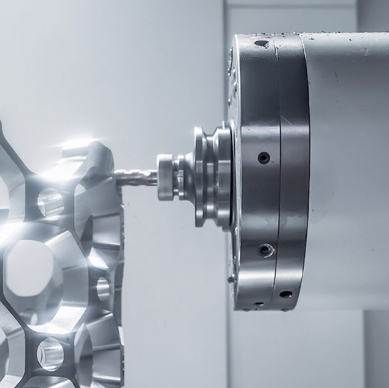
สิ่งที่ทำให้การขึ้นรูปชิ้นส่วนยานยนต์มีความท้าทายอย่างเป็นเอกลักษณ์คือ การผลิตในปริมาณสูง ความคลาดเคลื่อนที่แคบมาก และความคาดหวังให้ไม่มีข้อบกพร่องเลยแม้แต่น้อย ตัวอย่างเช่น โมเดลยานยนต์หนึ่งรุ่นอาจต้องการชิ้นส่วนแบบหนึ่ง (เช่น ที่ยึด) จำนวน 50,000 ชิ้นต่อปี — ทุกชิ้นต้องเหมือนกันทุกประการ และทุกจุดที่ดัดต้องอยู่ภายในเกณฑ์ที่กำหนด นี่คือจุดที่การสร้างต้นแบบอย่างรวดเร็ว (rapid prototyping) มีคุณค่าอย่างยิ่ง โดยช่วยให้ผู้ผลิตสามารถตรวจสอบและยืนยันการออกแบบก่อนลงทุนในการผลิตแม่พิมพ์สำหรับการผลิตจริง ซัพพลายเออร์ชั้นนำ เช่น Shaoyi (Ningbo) Metal Technology นำเสนอการสร้างต้นแบบอย่างรวดเร็วภายใน 5 วัน โดยเฉพาะเพื่อสนับสนุนขั้นตอนการตรวจสอบและยืนยันการออกแบบนี้ ซึ่งจะช่วยให้มั่นใจได้ว่าพารามิเตอร์การดัดและพฤติกรรมของวัสดุได้รับการยืนยันแล้วก่อนเริ่มการผลิตในระดับเต็มรูปแบบ
ข้อกำหนดด้านความแม่นยำสำหรับชิ้นส่วนโครงสร้าง
ลองนึกภาพว่าคุณกำลังมองหาร้านโดมิโนส์ใกล้ตัวคุณในช่วงดึก — คุณต้องการความน่าเชื่อถือเมื่อมันสำคัญ ชิ้นส่วนโครงสร้างยานยนต์ก็ต้องการความน่าเชื่อถือแบบเดียวกันนี้ แต่ระดับความสำคัญนั้นเพิ่มขึ้นอย่างมาก เนื่องจากเกี่ยวข้องโดยตรงกับชีวิตของมนุษย์ ข้อกำหนดด้านความแม่นยำสำหรับชิ้นส่วนเหล่านี้สูงกว่าที่งานผลิตส่วนใหญ่ต้องการ
ชิ้นส่วนโครงสร้างต้องตอบสนองความต้องการหลายประการพร้อมกัน:
- ความแม่นยำของขนาด: รูสำหรับยึดต้องจัดแนวให้พอดีกับชิ้นส่วนที่เชื่อมต่อกันทั่วทั้งยานพาหนะ — ตัวยึดที่เบี่ยงเบนตำแหน่งไปเพียง 0.5 มม. อาจทำให้ไม่สามารถประกอบได้ หรือก่อให้เกิดจุดสะสมแรงเครียด
- ความแม่นยำด้านมุม: มุมการดัดของชิ้นส่วนระบบช่วงล่างส่งผลต่อเรขาคณิตการจัดแนวล้อ — ความคลาดเคลื่อนเพียง 0.5 องศาอาจสะสมและส่งผลกระทบต่อทั้งระบบพวงมาลัยและระบบช่วงล่าง
- ความสม่ำเสมอของวัสดุ: การคำนวณโครงสร้างสมมุติค่าความแข็งแรงขณะไหล (yield strength) และค่าการยืดตัว (elongation properties) ที่เฉพาะเจาะจง — ความแปรผันของวัสดุจึงส่งผลโดยตรงต่อความแปรผันของระยะปลอดภัย (safety margin)
- ความสมบูรณ์ของพื้นผิว: รอยแตก รอยฉีก หรือความบางเกินไปบริเวณโซนการดัด จะกลายเป็นจุดเริ่มต้นของการล้มเหลวภายใต้โหลดแบบวนซ้ำ
- ความสามารถในการทำซ้ำ: ชิ้นส่วนที่ 50,000 ต้องตรงกับชิ้นส่วนชิ้นแรก — ความแปรผันของกระบวนการที่ยอมรับได้สำหรับชิ้นส่วนตกแต่งจะกลายเป็นสิ่งที่ไม่สามารถยอมรับได้สำหรับชิ้นส่วนโครงสร้าง
การตอบสนองความต้องการเหล่านี้จำเป็นต้องมีการควบคุมกระบวนการอย่างชาญฉลาด เครื่องดัดโลหะแบบ CNC ที่มีระบบวัดมุมแบบเรียลไทม์สามารถปรับค่าโดยอัตโนมัติเพื่อชดเชยความแปรผันของวัสดุ ระบบตัดด้วยเลเซอร์รักษาระดับคุณภาพของขอบให้คงที่ ซึ่งช่วยป้องกันการเกิดจุดรวมแรงดัน (stress concentrations) บริเวณแนวการดัด และการสนับสนุนการออกแบบเพื่อความสะดวกในการผลิต (Design for Manufacturability: DFM) อย่างครอบคลุมจะช่วยระบุปัญหาที่อาจเกิดขึ้นก่อนเริ่มการผลิต — ไม่ใช่หลังจากที่มีการจัดส่งชิ้นส่วนไปแล้วหลายพันชิ้น
รอบการพัฒนาสำหรับชิ้นส่วนโครงสร้างมักประกอบด้วยการสร้างต้นแบบอย่างกว้างขวาง ตัวอย่างจริงจะผ่านการทดสอบการดัด การวิเคราะห์ความเหนื่อยล้า และการจำลองการชนเพื่อตรวจสอบความสอดคล้องกัน ระยะการตรวจสอบและยืนยันนี้ มักถูกบีบให้สั้นลงตามกรอบเวลาการพัฒนาที่เข้มงวด จึงได้รับประโยชน์อย่างมากจากพันธมิตรด้านการผลิตที่สามารถจัดส่งชิ้นส่วนต้นแบบภายในไม่กี่วัน แทนที่จะใช้เวลาหลายสัปดาห์
ใบรับรองคุณภาพที่สำคัญ
ผู้ผลิตรถยนต์ตรวจสอบอย่างไรเพื่อให้มั่นใจว่าซัพพลายเออร์ของตนสามารถจัดส่งชิ้นส่วนความแม่นยำได้อย่างสม่ำเสมอ? ผ่านการรับรองระบบการจัดการคุณภาพที่เข้มงวด ซึ่งตรวจสอบทุกด้านของกระบวนการผลิต
การรับรองมาตรฐาน IATF 16949 ถือเป็นมาตรฐานทองคำสำหรับซัพพลายเออร์ในอุตสาหกรรมยานยนต์ ซึ่งอ้างอิงจากมาตรฐาน ISO 9001 แต่ขยายขอบเขตข้อกำหนดออกไปไกลกว่านั้น โดย IATF 16949 ครอบคลุมความต้องการเฉพาะด้านของการผลิตรถยนต์:
- คุณภาพสม่ำเสมอ: มีการติดตามและวัดกระบวนการผลิตเพื่อเพิ่มประสิทธิภาพการผลิตสูงสุด และส่งมอบผลลัพธ์ที่สม่ำเสมอในทุกการผลิต
- ลดความแตกต่างของผลิตภัณฑ์: กระบวนการผลิตที่ได้รับการทบทวนและปรับปรุงอย่างต่อเนื่อง ทำให้มั่นใจได้ว่าชิ้นส่วนโลหะจะสอดคล้องกับข้อกำหนดด้านประสิทธิภาพสูงของยานพาหนะอย่างสม่ำเสมอ ไม่ว่าจะนำไปใช้งานในบริบทใด
- ซุปพลายเชนที่น่าเชื่อถือ การรับรองนี้ได้รับการยอมรับในระดับสากล และเป็นเกณฑ์มาตรฐานในการคัดเลือกซัพพลายเออร์ รวมทั้งการสร้างความร่วมมือที่แข็งแกร่งและเชื่อถือได้มากยิ่งขึ้น
- การลดขยะ: กระบวนการผลิตที่มีประสิทธิภาพ ระบบการจัดการที่ได้รับการปรับปรุง และการจัดสรรทรัพยากรอย่างเหมาะสม ช่วยลดของเสียให้น้อยที่สุด ขณะเดียวกันก็ตอบสนองต่อโครงการด้านสิ่งแวดล้อม
- การป้องกันข้อบกพร่อง: กระบวนการขึ้นรูปโลหะ การผลิต การเชื่อม และการตกแต่งผิวผ่านการทดสอบและพิสูจน์แล้วว่าสามารถตอบสนองข้อกำหนดด้านความปลอดภัยของผลิตภัณฑ์ พร้อมทั้งลดข้อบกพร่องให้น้อยที่สุด
- ความพึงพอใจของลูกค้าเพิ่มขึ้น: หลักการบริหารคุณภาพเน้นการมุ่งเน้นลูกค้าอย่างเข้มแข็งและขั้นตอนการทำงานที่ได้รับการปรับปรุง เพื่อให้มั่นใจในการจัดส่งบริการอย่างสม่ำเสมอ
นอกเหนือจากมาตรฐาน IATF 16949 ผู้จัดจำหน่ายชิ้นส่วนยานยนต์อาจมีใบรับรองเพิ่มเติมที่เกี่ยวข้องกับการใช้งานเฉพาะด้าน ซึ่งมาตรฐาน ISO 14001 ครอบคลุมการจัดการด้านสิ่งแวดล้อม — ซึ่งมีความสำคัญเพิ่มขึ้นเรื่อยๆ ตามเป้าหมายด้านความยั่งยืนของผู้ผลิตรถยนต์ ส่วนมาตรฐาน OHSAS 18001 (หรือมาตรฐาน ISO 45001 ซึ่งเป็นมาตรฐานรุ่นต่อมา) ครอบคลุมด้านสุขภาพและความปลอดภัยในการทำงาน นอกจากนี้ ข้อกำหนดเฉพาะของลูกค้าจากผู้ผลิตรถยนต์รายใหญ่ (OEMs) มักจะเพิ่มข้อกำหนดด้านเอกสารและการติดตามย้อนกลับให้ลึกซึ้งยิ่งกว่ามาตรฐานทั่วไป
สำหรับวิศวกรและผู้เชี่ยวชาญด้านการจัดซื้อที่กำลังประเมินพันธมิตรในการผลิตชิ้นส่วน ใบรับรองเหล่านี้ให้หลักฐานยืนยันความสามารถอย่างเป็นกลาง ผู้จัดจำหน่ายที่ได้รับการรับรองตามมาตรฐาน IATF 16949 ได้แสดงให้เห็น — ผ่านการตรวจสอบโดยบุคคลภายนอก — ว่าระบบการจัดการคุณภาพของตนสอดคล้องกับข้อกำหนดของอุตสาหกรรมยานยนต์ การยืนยันนี้ครอบคลุมมากกว่าเพียงความสามารถของอุปกรณ์เท่านั้น แต่ยังรวมถึงการควบคุมกระบวนการ การฝึกอบรมพนักงาน การจัดการซัพพลายเออร์ และระบบการปรับปรุงอย่างต่อเนื่อง
เมื่อเลือกคู่ค้าสำหรับบริการตัดและดัดโลหะในอุตสาหกรรมยานยนต์ สถานะการรับรองควรจัดอยู่ในลำดับต้นๆ ของเกณฑ์การประเมินของท่าน การลงทุนที่ผู้จัดจำหน่ายชิ้นส่วนยานยนต์ดำเนินการเพื่อบรรลุและรักษาการรับรองเหล่านี้ — เช่น การตรวจสอบประจำปี การจัดทำเอกสารขั้นตอนการทำงาน และระบบการดำเนินการแก้ไขข้อบกพร่อง — ส่งผลโดยตรงต่อคุณภาพที่สม่ำเสมอของชิ้นส่วนที่ท่านได้รับ บริษัทต่างๆ เช่น Shaoyi แสดงให้เห็นถึงความมุ่งมั่นนี้ผ่านการรับรองมาตรฐาน IATF 16949 ซึ่งผสานการประกันคุณภาพเข้ากับข้อได้เปรียบในการดำเนินงาน เช่น การเสนอราคาภายใน 12 ชั่วโมง ซึ่งช่วยให้ห่วงโซ่อุปทานยานยนต์ดำเนินงานได้อย่างมีประสิทธิภาพ
การเข้าใจความต้องการเฉพาะของงานแปรรูปชิ้นส่วนยานยนต์จะช่วยให้ท่านเห็นคุณค่าในสิ่งที่ทำให้ผู้จัดจำหน่ายที่มีคุณสมบัติเหมาะสมแตกต่างจากผู้ที่เพียงอ้างว่ามีศักยภาพเท่านั้น แต่แล้วท่านจะประเมินคู่ค้าด้านการแปรรูปโลหะที่อาจเป็นไปได้อย่างไร? ส่วนสุดท้ายของปริศนานี้คือการกำหนดเกณฑ์ที่ชัดเจนสำหรับการเลือกคู่ค้าด้านการแปรรูปโลหะที่เหมาะสมที่สุดสำหรับความต้องการเฉพาะของท่าน
การเลือกคู่ค้าด้านการแปรรูปโลหะที่เหมาะสม
การค้นหาผู้ให้บริการตัดและดัดโลหะที่เหมาะสมนั้นรู้สึกคล้ายกับการค้นหาร้านโพปอายส์ใกล้ตัวคุณเมื่อคุณหิว — คุณต้องการทั้งคุณภาพ ความน่าเชื่อถือ และความรวดเร็วในการตอบสนองในหนึ่งเดียว แต่ต่างจากมื้ออาหารจานด่วน การเลือกพันธมิตรด้านการผลิต (fabrication partner) นั้นมีผลกระทบต่อผลลัพธ์ของโครงการคุณเป็นเวลาหลายเดือนหรือหลายปีข้างหน้า การเลือกผิดอาจทำให้คุณสูญเสียทั้งเงิน ทั้งเวลา และอาจกระทบต่อชื่อเสียงของคุณต่อลูกค้าปลายทางด้วย
แล้วคุณจะแยกผู้ผลิตที่มีศักยภาพจริงออกจากผู้ที่เพียงอ้างว่ามีความเชี่ยวชาญได้อย่างไร? โดยการประเมินเกณฑ์เฉพาะที่สามารถทำนายประสิทธิภาพการทำงานได้ก่อนที่คุณจะมอบหมายโครงการให้พวกเขา ลองมาสร้างกรอบแนวคิดสำหรับการตัดสินใจสำคัญนี้อย่างมั่นใจกัน
การประเมินความสามารถทางเทคนิค
อุปกรณ์และความเชี่ยวชาญของผู้ผลิตนั้นเป็นรากฐานสำคัญของทุกสิ่งที่พวกเขาสามารถส่งมอบได้ ตามแนวทางอุตสาหกรรมด้านการคัดเลือกซัพพลายเออร์ การทำความเข้าใจขีดความสามารถของโรงงานก่อนขอใบเสนอราคา จะช่วยป้องกันการสูญเสียเวลาโดยเปล่าประโยชน์และลดความคาดหวังที่ไม่สอดคล้องกัน
เริ่มต้นด้วยการจับคู่ขีดความสามารถของพวกเขาให้สอดคล้องกับความต้องการเฉพาะของคุณ:
- วิธีการตัดที่มีให้บริการ: พวกเขามีบริการตัดด้วยเลเซอร์ พลาสม่า หรือเจ็ทน้ำ หรือทั้งสามแบบหรือไม่? แต่ละวิธีเหมาะกับวัสดุและขนาดความหนาที่แตกต่างกัน
- ความสามารถของเครื่องดัด (Press brake capacity): ตรวจสอบให้แน่ใจว่ากำลังอัด (tonnage) และความยาวของโต๊ะเครื่องดัด (bed length) สอดคล้องกับข้อกำหนดของชิ้นส่วนคุณ — เครื่องดัด 100 ตันจะไม่สามารถดัดชิ้นส่วนที่ต้องการแรงดัด 300 ตันได้
- ใบรับรองการเชื่อม: หากชิ้นส่วนของคุณต้องการการเชื่อม โปรดยืนยันว่าช่างเชื่อมของพวกเขาได้รับการรับรองที่เหมาะสมสำหรับวัสดุและงานประยุกต์ใช้ของคุณ
- การผสานรวมการกลึงด้วย CNC: ชิ้นส่วนที่ต้องการรูเจาะหรือฟีเจอร์รองอื่นๆ ที่มีความแม่นยำสูงจะได้รับประโยชน์จากการมีศักยภาพในการกลึงภายในโรงงาน
- ตัวเลือกการตกแต่งผิว: การเคลือบผง การชุบโลหะ หรือการเคลือบพิเศษอื่นๆ ที่ดำเนินการภายในโรงงานจะช่วยลดระยะเวลาการผลิตและปัญหาด้านการประสานงาน
โรงงานแบบครบวงจรที่ผสานรวมทุกกระบวนการไว้ภายใต้หลังคาเดียวกันจะทำให้โครงการทั้งหมดของคุณดำเนินไปอย่างราบรื่น ผู้เชี่ยวชาญด้านการขึ้นรูปชิ้นส่วนระบุว่า การผสานรวมนี้ช่วยให้ควบคุมการผลิตได้อย่างแม่นยำยิ่งขึ้น มีเวลาส่งมอบที่รวดเร็วขึ้น และรักษามาตรฐานคุณภาพอย่างสม่ำเสมอ เมื่อเปรียบเทียบกับโรงงานที่จ้างภายนอกสำหรับกระบวนการสำคัญ
ใบรับรองที่ควรตรวจสอบ
ใบรับรองบอกคุณได้มากกว่าการนำเสนอเพื่อการขายเสมอ ใบรับรองเหล่านี้แสดงถึงการรับรองจากบุคคลที่สามว่าระบบการจัดการคุณภาพของผู้จัดจำหน่ายสอดคล้องกับมาตรฐานที่มีการจัดทำเป็นลายลักษณ์อักษร — และยังคงรักษาไว้ผ่านการตรวจสอบอย่างสม่ำเสมอซึ่งสามารถตรวจจับการลดลงของคุณภาพได้
ใบรับรองสำคัญที่ควรพิจารณา ได้แก่:
- ISO 9001: ใบรับรองการจัดการคุณภาพขั้นพื้นฐาน ซึ่งแสดงให้เห็นถึงกระบวนการที่มีการจัดทำเป็นลายลักษณ์อักษรและระบบการปรับปรุงอย่างต่อเนื่อง
- IATF 16949: จำเป็นสำหรับการใช้งานในอุตสาหกรรมยานยนต์ — ใบรับรองนี้ขยายขอบเขตของ ISO 9001 ด้วยข้อกำหนดเฉพาะสำหรับอุตสาหกรรมยานยนต์ ทั้งในด้านการป้องกันข้อบกพร่องและการจัดการห่วงโซ่อุปทาน
- AS9100: เทียบเท่ากับมาตรฐานอวกาศ ซึ่งเพิ่มข้อกำหนดด้านการติดตามแหล่งที่มา การจัดการโครงสร้าง (configuration management) และการลดความเสี่ยง
- การรับรองจากสมาคมการเชื่อมอเมริกัน: คุณสมบัติเฉพาะด้านการเชื่อม ซึ่งยืนยันความสามารถของผู้ปฏิบัติงานและคุณสมบัติของการดำเนินการเชื่อม
- การรับรองวัสดุ: การยืนยันว่าวัสดุที่เข้ามาสอดคล้องกับข้อกำหนด ผ่านรายงานผลการทดสอบจากโรงงานผลิต (mill test reports) และระบบการติดตามแหล่งที่มา
อย่าเพียงแต่รับรองข้ออ้างเท่านั้น — ขอสำเนาใบรับรองและตรวจสอบสถานะปัจจุบันของใบรับรองเหล่านั้น ใบรับรองอาจหมดอายุเมื่อบริษัทล้มเหลวในการสอบทาน (audit) หรือหยุดลงทุนตามที่จำเป็นเพื่อรักษาใบรับรองไว้ การที่ผู้ผลิตชิ้นส่วนแสดงใบรับรองที่หมดอายุอย่างภาคภูมิใจ ย่อมก่อให้เกิดคำถามสำคัญต่อความมุ่งมั่นด้านคุณภาพของพวกเขา
ระยะเวลาการดำเนินการและการคาดหวังด้านการสื่อสาร
คุณพบร้านวาฟเฟิลเฮาส์ใกล้ตัวคุณที่เปิดให้บริการตอนตี 3 เพราะคุณต้องการอาหารเมื่อคุณต้องการ — ไม่ใช่ตามตารางเวลาของผู้อื่น หลักการเดียวกันนี้ก็ใช้ได้กับพันธมิตรด้านการผลิตชิ้นส่วนเช่นกัน ความพร้อมในการตอบสนองในระยะเสนอราคา (quoting phase) สะท้อนถึงความพร้อมในการตอบสนองในระหว่างกระบวนการผลิต
ประเมินรูปแบบการสื่อสารก่อนตัดสินใจร่วมงาน:
- ระยะเวลาตอบกลับใบเสนอราคา: ความเร็วในการตอบกลับใบเสนอราคา (RFQs) ของพวกเขาเป็นอย่างไร? ผู้นำอุตสาหกรรมอย่าง Shaoyi (Ningbo) Metal Technology สามารถจัดทำใบเสนอราคาภายใน 12 ชั่วโมง — ซึ่งเป็นมาตรฐานที่แสดงให้เห็นถึงทั้งศักยภาพและความมุ่งมั่นต่อลูกค้า
- การเข้าถึงด้านเทคนิค: คุณสามารถพูดคุยกับวิศวกรโดยตรงซึ่งเข้าใจการใช้งานเฉพาะของคุณได้หรือไม่ หรือคุณจะต้องสื่อสารผ่านตัวแทนฝ่ายขายเท่านั้น?
- คุณภาพการสนับสนุน DFM: พวกเขาสามารถระบุการปรับปรุงการออกแบบได้อย่างกระตือรือร้นหรือไม่ หรือเพียงแต่เสนอราคาตามสิ่งที่คุณส่งมาโดยไม่มีความคิดเห็นใดๆ?
- ความถี่ในการอัปเดตโครงการ: คุณจะได้รับการสื่อสารอย่างไรในระหว่างกระบวนการผลิต? การอัปเดตข้อมูลแบบกระตือรือร้นช่วยป้องกันไม่ให้เกิดความประหลาดใจ
- แนวทางการแก้ไขปัญหา: พวกเขาจัดการกับปัญหาที่เกิดขึ้นอย่างไร? ขอตัวอย่างความท้าทายที่ผ่านมาและวิธีการแก้ไข
การสนับสนุนการออกแบบเพื่อการผลิต (Design for Manufacturability) อย่างครอบคลุมสมควรได้รับความสนใจเป็นพิเศษ ผู้ให้บริการแปรรูปที่ดีที่สุดจะตรวจสอบแบบแปลนของคุณก่อนเสนอราคา เพื่อระบุปัญหาที่อาจเกิดขึ้น เช่น ลำดับการดัด (bend sequencing), ความเป็นไปได้ในการบรรลุค่าความคลาดเคลื่อนที่กำหนด (tolerance achievability) หรือการเลือกวัสดุ แนวทางการทำงานร่วมกันนี้—ซึ่งแสดงให้เห็นชัดเจนผ่านผู้จัดจำหน่ายที่เสนอการสร้างต้นแบบแบบเร่งด่วนภายใน 5 วัน เพื่อยืนยันความถูกต้องของแบบแปลนก่อนเข้าสู่ขั้นตอนการผลิตจริง—ช่วยประหยัดค่าใช้จ่ายและป้องกันความล่าช้า ซึ่งการแก้ไขปัญหาแบบตอบสนองภายหลังไม่สามารถทำได้เท่าเทียม
รายการตรวจสอบการประเมินผู้ให้บริการ
ก่อนเลือกผู้ให้บริการตัดและดัดโลหะ โปรดประเมินเกณฑ์เหล่านี้อย่างเป็นระบบ:
- การตรวจสอบประสบการณ์: จำนวนปีที่ดำเนินธุรกิจ ตัวอย่างโครงการที่คล้ายคลึงกัน และคำรับรองจากลูกค้าที่ใช้งานในแอปพลิเคชันที่ใกล้เคียงกัน
- การตรวจสอบอุปกรณ์: อุปกรณ์ที่ทันสมัยและได้รับการดูแลรักษาอย่างดี เหมาะสมกับประเภทและขนาดความหนาของวัสดุที่คุณใช้
- การประเมินศักยภาพการผลิต: ความสามารถในการรองรับปริมาณงานของคุณโดยไม่กระทบต่อคุณภาพหรือกำหนดเวลา
- สถานะการรับรอง: ใบรับรองที่มีผลบังคับใช้อยู่ในปัจจุบันและเกี่ยวข้อง โดยผ่านการตรวจสอบใบรับรอง
- กระบวนการควบคุมคุณภาพ: ขั้นตอนการตรวจสอบที่มีการจัดทำเป็นเอกสาร อุปกรณ์วัด (CMMs, เครื่องวัดขนาด) และโปรโตคอลการตรวจสอบชิ้นงานต้นแบบ
- ศักยภาพ DFM มีทรัพยากรด้านวิศวกรรมพร้อมให้บริการตรวจสอบแบบจำลองการออกแบบและเสนอแนะแนวทางเพิ่มประสิทธิภาพ
- ความเร็วในการทำต้นแบบ: สามารถจัดส่งตัวอย่างได้อย่างรวดเร็วเพื่อการตรวจสอบยืนยันการออกแบบก่อนตัดสินใจเข้าสู่การผลิตจริง
- ความรวดเร็วในการสื่อสาร: ระยะเวลาตอบกลับใบเสนอราคา ความพร้อมในการให้คำปรึกษาเชิงเทคนิค และความถี่ในการอัปเดตข้อมูล
- ความมั่นคงทางการเงิน: ธุรกิจที่ดำเนินงานมาอย่างมั่นคง มีทรัพยากรเพียงพอสำหรับการลงทุนในอุปกรณ์และบุคลากร
- ความน่าเชื่อถือของห่วงโซ่อุปทาน: การจัดหาวัสดุ ระบบการติดตามที่มาของวัสดุ และความสัมพันธ์กับผู้จัดจำหน่ายสำรอง
ให้กำหนดน้ำหนักของเกณฑ์เหล่านี้ตามลำดับความสำคัญเฉพาะของคุณ โดยการผลิตต้นแบบจะให้ความสำคัญกับความเร็วและความยืดหยุ่น ขณะที่การผลิตรถยนต์ในปริมาณสูงจำเป็นต้องมีสถานะการรับรองและควบคุมกระบวนการอย่างเข้มงวด ส่วนชิ้นส่วนตกแต่งอาจเน้นความสามารถในการขึ้นรูปผิวสุดท้าย (finishing capability) ขณะที่ชิ้นส่วนโครงสร้างต้องการการติดตามที่มาของวัสดุและการจัดทำเอกสารการตรวจสอบ
พาร์ทเนอร์ด้านการผลิตที่เหมาะสมไม่เพียงแค่ผลิตชิ้นส่วนให้คุณเท่านั้น แต่ยังมีส่วนร่วมด้วยความรู้ด้านวิศวกรรม ตรวจจับปัญหาในการออกแบบก่อนเข้าสู่ขั้นตอนการผลิต และสื่อสารอย่างโปร่งใสและทันเวลาตลอดระยะเวลาความสัมพันธ์ของคุณ สำหรับแอปพลิเคชันระดับอุตสาหกรรมยานยนต์ซึ่งคุณภาพไม่สามารถยอมประนีประนอมได้ พาร์ทเนอร์อย่าง Shaoyi ผสมผสานการรับรองมาตรฐาน IATF 16949 เข้ากับการสนับสนุนการออกแบบเพื่อการผลิต (DFM) อย่างครอบคลุม และความสามารถในการผลิตต้นแบบอย่างรวดเร็ว ซึ่งแสดงให้เห็นถึงแนวทางแบบครบวงจรที่เปลี่ยนผู้จัดจำหน่ายให้กลายเป็นพาร์ทเนอร์ด้านการผลิตที่แท้จริง
การลงทุนเวลาเพื่อประเมินอย่างละเอียดจะส่งผลตอบแทนในทุกโครงการที่ตามมา ผู้ผลิตชิ้นส่วนที่คุณเลือกวันนี้จะกำหนดคุณภาพ ต้นทุน และความน่าเชื่อถือของชิ้นส่วนที่คุณจะจัดส่งไปยังลูกค้าเป็นเวลาหลายปีข้างหน้า
คำถามที่พบบ่อยเกี่ยวกับบริการตัดและดัดโลหะ
1. การดัดโลหะมีค่าใช้จ่ายเท่าใด?
ต้นทุนการดัดโลหะมักอยู่ในช่วง 1–5 ดอลลาร์สหรัฐต่อจุดดัดสำหรับงานพื้นฐาน แต่ราคาอาจแตกต่างกันอย่างมากขึ้นอยู่กับชนิดของวัสดุ ความหนา ระดับความซับซ้อน และปริมาณการผลิต ค่าใช้จ่ายในการเตรียมระบบ เช่น การเขียนโปรแกรม CNC และการจัดวางเครื่องมือ จะเรียกเก็บไม่ว่าจะผลิตจำนวนเท่าใด ทำให้ต้นทุนต่อชิ้นสูงกว่าสำหรับต้นแบบเมื่อเทียบกับการผลิตจำนวนมาก ความคลาดเคลื่อนที่แคบขึ้น วัสดุพิเศษ เช่น สเตนเลสสตีล และกระบวนการรอง เช่น การกำจัดร่องรอยคม (deburring) หรือการตกแต่งผิว จะเพิ่มต้นทุนรวมทั้งหมด สำหรับงานความแม่นยำระดับยานยนต์ที่ต้องปฏิบัติตามมาตรฐาน IATF 16949 คุณควรคาดการณ์ราคาที่สูงกว่าปกติ ซึ่งสะท้อนถึงการควบคุมคุณภาพและการจัดทำเอกสารที่เข้มงวดยิ่งขึ้น
2. ค่าตัดโลหะอยู่ที่เท่าไร
ต้นทุนการตัดโลหะอยู่ในช่วง 0.50 ถึง 6.00 ดอลลาร์สหรัฐต่อฟุตเชิงเส้น ขึ้นอยู่กับวิธีการตัดและชนิดของวัสดุ การตัดด้วยเลเซอร์มักมีค่าใช้จ่าย 1.50–4.00 ดอลลาร์สหรัฐต่อฟุตสำหรับวัสดุบาง ๆ ในขณะที่การตัดด้วยเจ็ทน้ำมีราคาสูงกว่าประมาณสองเท่า เนื่องจากต้นทุนวัสดุกัดกร่อนที่ใช้สิ้นเปลือง การตัดด้วยพลาสม่าเป็นทางเลือกที่ประหยัดที่สุดสำหรับแผ่นเหล็กหนา โดยมีราคาโดยประมาณ 1.50–2.50 ดอลลาร์สหรัฐต่อฟุต ปัจจัยเพิ่มเติมที่ส่งผลต่อราคา ได้แก่ ความหนาของวัสดุ ความซับซ้อนของการตัด ประสิทธิภาพการจัดวางชิ้นงาน (nesting efficiency) และการที่จำเป็นต้องตกแต่งขอบหลังการตัดหรือไม่ เพื่อรองรับกระบวนการดัดในขั้นตอนถัดไป
3. วิธีการตัดแบบใดเหมาะสมที่สุดสำหรับแผ่นโลหะที่จะนำไปดัด?
การตัดด้วยเลเซอร์มักเป็นที่นิยมใช้สำหรับแผ่นโลหะที่จะนำไปขึ้นรูปด้วยการงอ เนื่องจากให้ขอบที่เรียบสะอาดและมีโซนที่ได้รับผลกระทบจากความร้อนน้อยมาก คุณภาพของขอบเช่นนี้ช่วยรับประกันสมบัติของวัสดุที่สม่ำเสมอตามแนวการงอ ส่งผลให้มุมที่ได้มีความแม่นยำสูง และลดความเสี่ยงของการเกิดรอยร้าวจุลภาค (micro-cracking) ลงอย่างมีนัยสำคัญ สำหรับโลหะผสมที่ไวต่อความร้อน หรืองานที่ต้องการไม่มีการบิดงอจากความร้อนเลยแม้แต่น้อย การตัดด้วยเจ็ทน้ำ (waterjet cutting) จะขจัดปัญหาความร้อนได้โดยสิ้นเชิง ส่วนการตัดด้วยพลาสมาเหมาะสำหรับเหล็กโครงสร้างที่มีความหนา โดยที่คุณภาพของขอบไม่ใช่ปัจจัยหลัก อย่างไรก็ตาม ชิ้นส่วนอาจจำเป็นต้องผ่านกระบวนการขัดขอบก่อนนำไปขึ้นรูปด้วยการงอแบบความแม่นยำสูง
4. ความแตกต่างระหว่างการงอแบบแอร์เบนดิ้ง (air bending) กับการงอแบบบอททอมเบนดิ้ง (bottom bending) คืออะไร
การดัดแบบอากาศ (Air bending) ใช้เพียงจุดสัมผัสสามจุด ได้แก่ ปลายของลูกแม่พิมพ์ (punch tip) และขอบทั้งสองข้างของแม่พิมพ์ (die edges) ซึ่งช่วยให้สามารถดัดมุมได้ในช่วง 90–180 องศาด้วยการตั้งค่าเครื่องมือเพียงชุดเดียว และใช้แรงน้อยมาก อย่างไรก็ตาม วิธีนี้ให้ความคลาดเคลื่อนของมุมกว้างขึ้น (+/- 0.5 ถึง 1 องศา) เนื่องจากความแปรผันของปรากฏการณ์สปริงแบ็ก (springback) ส่วนการดัดแบบกดที่ฐาน (bottom bending) จะบีบวัสดุให้แนบสนิทกับพื้นผิวของแม่พิมพ์ ทำให้ได้ความคลาดเคลื่อนของมุมที่แคบลงและควบคุมสปริงแบ็กได้ดีขึ้น แต่ต้องใช้แรงอัดมากขึ้น 2–3 เท่า และต้องใช้เครื่องมือเฉพาะสำหรับแต่ละมุมที่ต้องการ ดังนั้น ให้เลือกการดัดแบบอากาศเมื่อต้องการความยืดหยุ่นและการลงทุนในเครื่องมือที่ต่ำกว่า แต่ให้เลือกการดัดแบบกดที่ฐานเมื่อความแม่นยำของมุมที่สม่ำเสมอเป็นสิ่งสำคัญพอที่จะคุ้มค่ากับข้อกำหนดเพิ่มเติมด้านอุปกรณ์
5. ฉันจะเลือกคู่ค้าด้านการผลิตชิ้นส่วนโลหะที่เหมาะสมได้อย่างไร?
ประเมินพันธมิตรด้านการผลิตตามศักยภาพทางเทคนิคที่สอดคล้องกับความต้องการของคุณ ใบรับรองที่เกี่ยวข้อง (เช่น มาตรฐาน ISO 9001 สำหรับคุณภาพทั่วไป และมาตรฐาน IATF 16949 สำหรับการใช้งานในอุตสาหกรรมยานยนต์) รวมทั้งความรวดเร็วในการสื่อสาร ควรเลือกพันธมิตรที่ให้การสนับสนุนการออกแบบเพื่อการผลิต (DFM) อย่างครอบคลุม ซึ่งสามารถระบุแนวทางปรับปรุงการออกแบบได้อย่างกระตือรือร้น แทนที่จะเสนอราคาเพียงตามแบบที่คุณส่งมาเท่านั้น เวลาที่ใช้ในการจัดทำใบเสนอราคาสะท้อนถึงความรวดเร็วโดยรวมของผู้ให้บริการ — ผู้นำในอุตสาหกรรม เช่น Shaoyi สามารถจัดทำใบเสนอราคาได้ภายใน 12 ชั่วโมง โปรดตรวจสอบสภาพเครื่องจักร ความสามารถในการรองรับปริมาณการผลิตของคุณ รวมทั้งศักยภาพในการดำเนินกระบวนการตกแต่งชิ้นงานภายในโรงงานเอง สำหรับการใช้งานที่มีความสำคัญสูง ความสามารถในการสร้างต้นแบบอย่างรวดเร็ว (เช่น ใช้เวลาไม่เกิน 5 วัน) จะช่วยให้คุณสามารถตรวจสอบและยืนยันการออกแบบได้ก่อนตัดสินใจเข้าสู่ขั้นตอนการผลิตจริง