 ผลิตจำนวนน้อย แต่มีมาตรฐานสูง บริการสร้างต้นแบบอย่างรวดเร็วของเรามาพร้อมกับการตรวจสอบที่เร็วขึ้นและง่ายขึ้น —

บริการตัดโลหะแบบมีข้อมูลลับ: 9 ข้อกำหนดที่ผู้รับจ้างผลิตจะไม่บอกคุณ
การทำความเข้าใจเกี่ยวกับบริการตัดโลหะในอุตสาหกรรมการผลิตสมัยใหม่
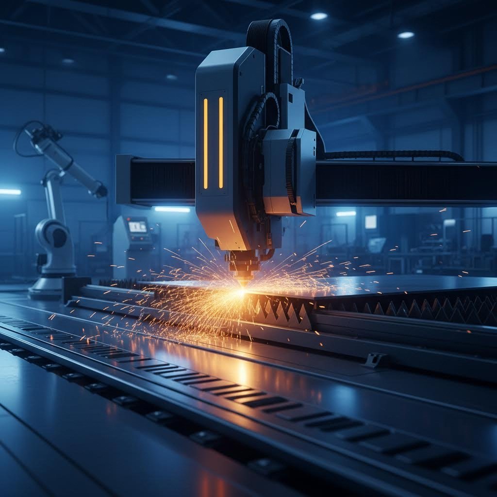
เมื่อคุณต้องการชิ้นส่วนโลหะสำหรับโครงการถัดไป คุณเคยสงสัยไหมว่าจริงๆ แล้วมีกระบวนการอะไรเกิดขึ้นเบื้องหลัง? บริการตัดโลหะเป็นกระบวนการผลิตขั้นพื้นฐานที่วัสดุขนาดใหญ่ถูกแยกออกอย่างแม่นยำเป็นชิ้นส่วนเล็กๆ หรือชิ้นส่วนที่มีรูปร่างตามแบบที่กำหนดไว้ ไม่ว่าคุณจะเป็นวิศวกรที่ระบุรายละเอียดชิ้นส่วน เป็น ผู้เชี่ยวชาญด้านจัดซื้อที่สรรหาผู้จัดจำหน่าย หรือผู้ซื้อที่ประเมินตัวเลือกต่างๆ การเข้าใจบริการเหล่านี้อาจหมายถึงความแตกต่างระหว่างความสำเร็จของโครงการและความผิดพลาดที่ส่งผลเสียทางการเงิน
ในการผลิตยุคใหม่ การตัดโลหะได้พัฒนาไปไกลกว่าการเลื่อยแบบง่ายๆ ปัจจุบันการตัดโลหะด้วยความแม่นยำครอบคลุมทุกอย่างตั้งแต่วิธีการเชิงกลแบบดั้งเดิมไปจนถึงเทคโนโลยีความร้อนขั้นสูงที่ควบคุมด้วยระบบคอมพิวเตอร์ แนวทางแต่ละแบบมีข้อดีและข้อจำกัดที่แตกต่างกัน ซึ่งส่งผลโดยตรงต่อคุณภาพ ระยะเวลา และงบประมาณของโครงการของคุณ
บริการตัดโลหะรวมถึงอะไรบ้าง
ให้คิดถึงบริการตัดโลหะเป็นคำรวมที่ครอบคลุมกระบวนการเฉพาะทางหลายประเภท แก่นหลักของบริการตัดคือการแยกชิ้นงานออกด้วยแรงเชิงกล พลังความร้อน หรือการกัดกร่อนด้วยอนุภาคความเร็วสูง ตามมาตรฐานอุตสาหกรรม วิธีการเหล่านี้สามารถแบ่งออกเป็นสองหมวดหมู่หลัก ได้แก่
- การตัดเชิงกล (การเลื่อย การตัดด้วยเครื่องเฉือน) ใช้แรงทางกายภาพหรือการกัดกร่อน โดยเกิดโซนที่ได้รับผลกระทบจากความร้อนน้อยมาก ลดความเสี่ยงที่วัสดุจะบิดงอ
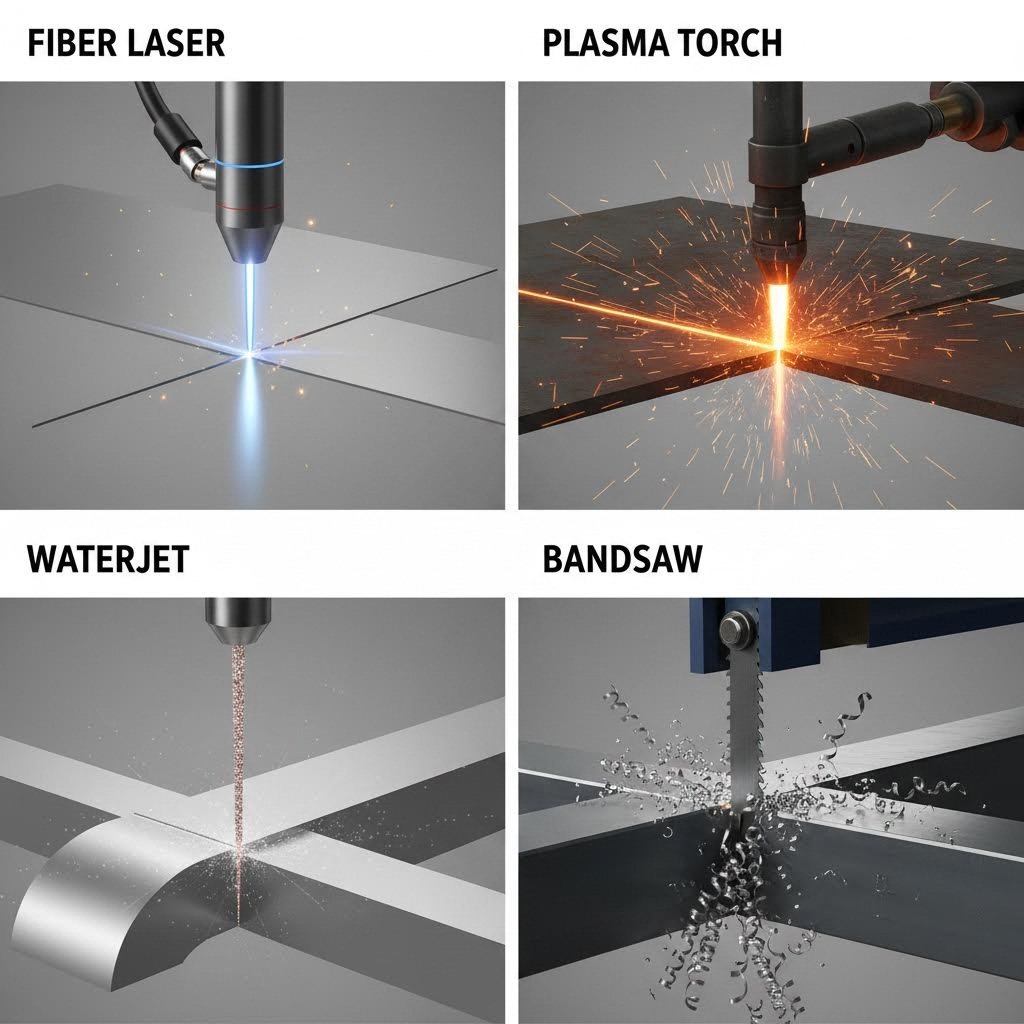
- การตัดด้วยความร้อน/การกัดกร่อน (เลเซอร์ พลาสม่า เวเตอร์เจ็ท) ใช้ความร้อนอย่างรุนแรงหรืออนุภาคขัดเร่งความเร็วเพื่อให้ได้รูปทรงเรขาคณิตที่ซับซ้อนมากขึ้นและรอยตัดที่แคบลง
หมวดหมู่หลักของบริการตัดโลหะที่คุณจะพบ ได้แก่:
- การตัดเลเซอร์: การตัดที่มีความแม่นยำสูงโดยใช้ลำแสงโฟกัสพร้อมระบบควบคุม CNC
- การตัดพลาสมา: การประมวลผลอย่างรวดเร็วของวัสดุนำไฟฟ้าหนาๆ โดยใช้ก๊าซที่ร้อนจัด
- การตัดไฮโดรเจ็ท: เทคนิคการตัดแบบเย็นโดยใช้น้ำภายใต้ความดันสูง เหมาะอย่างยิ่งสำหรับวัสดุที่ไวต่อความร้อน
- การดำเนินงานการเลื่อย: วิธีการเลื่อยแบบสายพานและเลื่อยวงกลมสำหรับหน้าตัดต่างๆ
- การกลึง CNC: การตัดด้วยความแม่นยำที่ควบคุมด้วยคอมพิวเตอร์สำหรับรูปทรงเรขาคณิตที่ซับซ้อน
เหตุใดการเข้าใจวิธีการตัดจึงสำคัญต่อโครงการของคุณ
นี่คือความจริง: ผู้รับจ้างผลิตอาจไม่อธิบายเหตุผลว่าทำไมพวกเขาจึงแนะนำวิธีหนึ่งมากกว่าวิธีอื่น แต่ทางเลือกนี้มีผลโดยตรงต่อผลลัพธ์ของโครงการของคุณ บริการตัดเหล็กที่ใช้เทคโนโลยีพลาสม่าสามารถทำงานได้อย่างรวดเร็วสำหรับวัสดุที่หนา ในขณะที่ระบบเลเซอร์ให้ค่าความคลาดเคลื่อนที่แน่นกว่าสำหรับชิ้นส่วนที่บาง การบริการตัดเพื่อการผลิตจำเป็นต้องชั่งน้ำหนักระหว่างความต้องการความแม่นยำกับข้อจำกัดด้านงบประมาณ
การประกันคุณภาพมีความสำคัญอย่างยิ่งเมื่อเลือกผู้ให้บริการ การได้รับการรับรองมาตรฐาน ISO เป็นตัวบ่งชี้พื้นฐานที่แสดงว่าผู้ผลิตมีกระบวนการและเอกสารที่สม่ำเสมอ สำหรับการใช้งานเฉพาะทาง เช่น ชิ้นส่วนอากาศยานหรือยานยนต์ อาจต้องมีใบรับรองเพิ่มเติมเพื่อให้มั่นใจในเรื่องความสามารถในการตรวจสอบย้อนกลับและความสอดคล้องตามมาตรฐานเฉพาะอุตสาหกรรม
ตลอดทั้งบทความนี้ คุณจะได้ค้นพบเกณฑ์สำคัญ 9 ประการที่ผู้รับจ้างผลิตมักไม่อธิบายให้ฟัง—ตั้งแต่ระดับความทนทานและข้อกำหนดวัสดุ ไปจนถึงขีดความสามารถของอุปกรณ์และปัจจัยด้านต้นทุน เมื่ออ่านจบ คุณจะมีความรู้เพียงพอที่จะถามคำถามที่ถูกต้องและตัดสินใจอย่างมีข้อมูลสำหรับโครงการตัดโลหะของคุณ
วิธีการตัดโลหะหลักและการประยุกต์ใช้งาน
คุณเคยยืนอยู่หน้าร้านงานโลหะดัดแปลงแล้วสงสัยไหมว่าทำไมพวกเขาถึงเสนอราคาตัดด้วยเลเซอร์สำหรับโครงการของคุณ ในขณะที่อีกรายหนึ่งกลับแนะนำการตัดด้วยพลาสม่า? คุณไม่ได้เป็นคนเดียวที่สงสัยเช่นนี้ ความจริงก็คือ เทคโนโลยีการตัดแต่ละประเภทมีจุดแข็งเฉพาะตัวในสถานการณ์ที่แตกต่างกัน และการเข้าใจความแตกต่างเหล่านี้สามารถช่วยประหยัดเงินค่าวัสดุและเวลาการผลิตได้หลายพันบาท มาดูรายละเอียดของการตัดโลหะ 4 วิธีหลักที่คุณมักจะพบเจอบ่อย เมื่อต้องสั่งซื้อบริการตัดโลหะด้วยเลเซอร์ หรือเทคโนโลยีการตัดอื่นๆ กัน
คำอธิบายเทคโนโลยีการตัดด้วยเลเซอร์
การตัดด้วยเลเซอร์ใช้ลำแสงที่เข้มข้นมากในการทำให้วัสดุละลาย ไหม้ หรือกลายเป็นไอตามเส้นทางที่โปรแกรมไว้ แต่นี่คือสิ่งที่ผู้รับจ้างงานโลหะส่วนใหญ่จะไม่บอกคุณ — มีเทคโนโลยีเลเซอร์สองแบบที่แตกต่างกันโดยสิ้นเชิง การเลือกใช้ผิดประเภทอาจทำให้ผลลัพธ์ของคุณลดคุณภาพลงได้
เลเซอร์ไฟเบอร์ สร้างแสงขึ้นมาโดยใช้ไฟเบอร์ออปติกที่ผสมธาตุหายาก เช่น ไยเทอร์เบียม อ้างอิงจาก รายงานการวิเคราะห์อุตสาหกรรมของ Superstar Laser ปี 2025 , เลเซอร์ไฟเบอร์ทำงานที่ความยาวคลื่น 1.06 ไมโครเมตร ซึ่งสั้นกว่าเลเซอร์ CO2 ถึงสิบเท่า ความยาวคลื่นที่สั้นกว่านี้ถูกดูดซับได้อย่างมีประสิทธิภาพมากขึ้นโดยโลหะ ทำให้เลเซอร์ไฟเบอร์กลายเป็นตัวเลือกอันดับหนึ่งสำหรับบริการตัดพลาสม่าเหล็กกล้าและงานแปรรูปโลหะทั่วไป
เลเซอร์ CO2 ใช้ก๊าซผสมเป็นตัวกลางในการสร้างแสงเลเซอร์ โดยผลิตแสงที่ความยาวคลื่น 10.6 ไมโครเมตร ความยาวคลื่นที่ยาวกว่านี้เหมาะอย่างยิ่งกับวัสดุอินทรีย์ เช่น ไม้ อคริลิก และหนัง แต่กลับมีข้อจำกัดกับโลหะสะท้อนแสง เนื่องจากลำแสงจะถูกสะท้อนออกจากพื้นผิวของทองแดง เหลือง และอลูมิเนียม เป็นผลให้สูญเสียพลังงานจำนวนมาก
คุณควรระบุใช้แต่ละประเภทเมื่อใด พิจารณาแนวทางปฏิบัติเหล่านี้:
- เลเซอร์ไฟเบอร์: งานแปรรูปแผ่นโลหะ ชิ้นส่วนยานยนต์ ชิ้นส่วนอุตสาหกรรม การแปรรูปสเตนเลส อลูมิเนียม และทองเหลือง
- เลเซอร์ CO2: ป้ายโฆษณา งานฝีมือ ผลิตภัณฑ์ไม้ ป้ายแสดงผลจากอคริลิก และโครงการที่ใช้วัสดุผสม
หากคุณกำลังค้นหา "ตัดเหล็กสแตนเลสด้วยเลเซอร์ใกล้ฉัน" คุณจะต้องการผู้ผลิตที่ใช้อุปกรณ์เลเซอร์ไฟเบอร์ ความได้เปรียบด้านความเร็วนั้นชัดเจนมาก—เลเซอร์ไฟเบอร์ 4 กิโลวัตต์สามารถตัดเหล็กสแตนเลสหนา 1 มม. ได้เร็วกว่า 30 เมตรต่อนาที ในขณะที่ระบบ CO2 เทียบเท่าทำได้เพียง 10-12 เมตรต่อนาที
การเปรียบเทียบระหว่างการตัดด้วยพลาสมาและการตัดด้วยน้ำแรงดันสูง
นอกจากการตัดโลหะด้วยเลเซอร์แล้ว ยังมีอีกสองวิธีที่ใช้ความร้อนและการกัดกร่อน ซึ่งเป็นที่นิยมในการประยุกต์ใช้งานในอุตสาหกรรม การเข้าใจว่าเมื่อใดควรใช้วิธีใดจะช่วยให้คุณหลีกเลี่ยงการระบุข้อกำหนดที่เกินจำเป็นหรือการลดทอนคุณภาพโดยไม่จำเป็น
การตัดพลาสม่า ใช้กระแสไฟฟ้าอาร์กและก๊าซอัดเพื่อละลายและพ่นตัดผ่านโลหะที่นำไฟฟ้าได้ มันเป็นเครื่องจักรหลักในการผลิตชิ้นงานขนาดใหญ่ โดยเฉพาะอย่างยิ่งบริการตัดด้วยพลาสมาแบบ CNC ที่จัดการกับแผ่นเหล็กหนา ตามข้อมูลจาก ข้อมูลการทดสอบจาก Wurth Machinery การตัดเหล็กหนา 1 นิ้วด้วยพลาสม่ามีความเร็วเร็วกว่าการตัดด้วยน้ำแรงดันสูงถึง 3-4 เท่า และต้นทุนการดำเนินงานต่ำกว่าประมาณครึ่งหนึ่งต่อความยาวหนึ่งฟุต
การตัดด้วยน้ำแรงดันสูง ใช้แนวทางที่แตกต่างอย่างสิ้นเชิง โดยการใช้น้ำภายใต้ความดันสูงผสมกับอนุภาคสารกัดกร่อนชนิดไพลินสังเคราะห์ (garnet) เพื่อขัดกร่อนวัสดุโดยไม่เกิดความร้อน กระบวนการตัดแบบเย็นนี้ช่วยกำจัดปัญหาโซนที่ได้รับผลกระทบจากความร้อน การบิดงอ และการแข็งตัวของวัสดุ ซึ่งเป็นปัจจัยสำคัญสำหรับชิ้นส่วนอากาศยานหรือโลหะผสมที่ไวต่อความร้อน
นี่คือกรณีที่แต่ละวิธีมีความเหมาะสมมากที่สุด:
- พลาสม่าเหมาะอย่างยิ่งสำหรับ: งานผลิตโครงสร้างเหล็ก งานผลิตอุปกรณ์หนัก การต่อเรือ และโครงการที่มีความหนาของวัสดุระหว่าง ½" ถึง 2" ขึ้นไป
- วอเตอร์เจ็ทเหมาะอย่างยิ่งสำหรับ: การตัดหินและกระจก ชิ้นส่วนอากาศยานที่ต้องการความแม่นยำโดยไม่เกิดการบิดงอจากความร้อน อุปกรณ์ในอุตสาหกรรมแปรรูปอาหาร และการตัดวัสดุหลายชนิดซ้อนกัน
ตลาดวอเตอร์เจ็ทกำลังเติบโตอย่างมาก โดยคาดว่าจะมีมูลค่าเกิน 2.39 พันล้านดอลลาร์ภายในปี 2034 จากความต้องการการตัดที่ไม่เกิดความร้อนในอุตสาหกรรมที่ต้องการความแม่นยำสูง
ตารางเปรียบเทียบวิธีการตัดอย่างสมบูรณ์
ก่อนขอใบเสนอราคา ให้ใช้ตารางเปรียบเทียบนี้เพื่อจับคู่ความต้องการของโครงการกับเทคโนโลยีการตัดที่เหมาะสมที่สุด:
| ปัจจัย | ไลเซอร์ไฟเบอร์ | เลเซอร์ co2 | พลาสม่า | เจ็ทน้ำ |
|---|---|---|---|---|
| ความเข้ากันของวัสดุ | โลหะ (เหล็ก โลหะสเตนเลส อลูมิเนียม ทองเหลือง ทองแดง) | อินทรีย์วัตถุ (ไม้, อะคริลิก, หนัง, ผ้า), โลหะบางชนิด | เฉพาะโลหะที่นำไฟฟ้าเท่านั้น | เกือบทุกวัสดุ ยกเว้นกระจกนิรภัย |
| ช่วงความหนา | 0.5 มม. ถึง 25 มม. ขึ้นไป (ด้วยระบบกำลังสูง) | ได้สูงสุดถึง 25 มม. สำหรับเหล็ก; เหมาะอย่างยิ่งกับวัสดุที่ไม่ใช่โลหะแบบบาง | 3 มม. ถึง 50 มม. ขึ้นไป (เหมาะสมที่สุดเมื่อเกิน 12 มม.) | ได้สูงสุดถึง 200 มม. ขึ้นไป ขึ้นอยู่กับวัสดุ |
| ความแม่นยำของความคลาดเคลื่อน (Precision Tolerance) | ±0.05 มม. ถึง ±0.1 มม. | ±0.1 มม. ถึง ±0.3 มม. | ±0.5 มม. ถึง ±1.5 มม. | ±0.1 มม. ถึง ±0.25 มม. |
| คุณภาพของรอยตัด | ยอดเยี่ยม; ขอบเรียบเนียน แทบไม่มีเครื่องหมายตกค้าง พร้อมสำหรับขั้นตอนการตกแต่ง | ดีถึงยอดเยี่ยมในวัสดุที่เข้ากันได้ | พื้นผิวหยาบกว่า; อาจต้องทำการตกแต่งเพิ่มเติม | พื้นผิวเรียบ ไม่มีโซนที่ได้รับผลกระทบจากความร้อน |
| ความเร็วในการตัด | เร็วมากบนโลหะบาง | ปานกลาง; ช้ากว่าไฟเบอร์บนโลหะ | เร็วบนโลหะตัวนำหนา | ช้าที่สุดโดยรวม |
| ราคาสัมพัทธ์ | ต้นทุนอุปกรณ์สูงกว่า; ต้นทุนการดำเนินงานต่ำกว่า | ต้นทุนอุปกรณ์ต่ำกว่า; ต้นทุนการดำเนินงานสูงกว่า | ต้นทุนอุปกรณ์ต่ำที่สุด; ต้นทุนการดำเนินงานปานกลาง | ต้นทุนอุปกรณ์สูงที่สุด; การใช้สารขัดสูง |
| เขตที่ได้รับผลกระทบจากความร้อน | น้อยที่สุด | ปานกลาง | สำคัญ | ไม่มี |
วิธีการตัดด้วยเลื่อยแบบดั้งเดิม
อย่ามองข้ามการตัดด้วยเลื่อยแบบธรรมดาเมื่อไม่จำเป็นต้องใช้วิธีตัดด้วยความร้อน เลื่อยสายพานและเลื่อยจานยังคงเป็นทางออกที่คุ้มค่าสำหรับการตัดตรง วัสดุแท่ง และการประมวลผลท่อ วิธีเหล่านี้ไม่ก่อให้เกิดโซนที่ได้รับผลกระทบจากความร้อน และสามารถจัดการกับหน้าตัดขนาดใหญ่ที่แม้แต่ระบบเลเซอร์กำลังสูงก็อาจทำงานได้ยาก
การตัดด้วยเลื่อยมีประโยชน์โดยเฉพาะสำหรับ:
- ตัดเหล็กเส้นกลม ท่อ และรูปทรงโครงสร้างตามความยาว
- ประมวลผลแผ่นโลหะที่หนามากซึ่งวิธีการทางความร้อนทำได้ยาก
- โครงการที่คำนึงถึงงบประมาณ โดยมีรูปร่างเรียบง่าย
- วัสดุที่ไวต่อความเครียดจากความร้อน
เมื่อคุณเข้าใจเทคโนโลยีการตัดหลักแล้ว สิ่งที่ควรพิจารณาต่อไปคือการเลือกวิธีที่เหมาะสมกับ การดำเนินงานการตัดด้วยเลื่อยเฉพาะทางและข้อกำหนดของอุปกรณ์ การเข้าใจศักยภาพของอุปกรณ์จะช่วยให้คุณประเมินได้ว่าผู้รับจ้างสามารถรองรับข้อกำหนดของโครงการคุณได้จริงหรือไม่
การดำเนินงานการตัดด้วยเลื่อยเฉพาะทางและศักยภาพของอุปกรณ์
คุณอาจเคยเห็นผู้ผลิตรายการบริการตัดด้วยเลื่อยบนเว็บไซต์ของพวกเขา เช่น การตัดด้วยเลื่อยตัด (cutoff sawing), การตัดแผ่น (plate sawing), การตัดตามรูปทรง (contour sawing) แต่คำเหล่านี้หมายความว่าอย่างไรต่อโครงการของคุณกันแน่? ต่างจากเทคโนโลยีการตัดด้วยเลเซอร์หรือพลาสมา ซึ่งตัวเทคโนโลยีเองจะกำหนดขีดความสามารถได้ การตัดด้วยเลื่อยจะถูกจัดประเภทตามชนิดของการตัดและลักษณะของวัสดุที่ต้องจัดการ การเข้าใจความแตกต่างเหล่านี้จะช่วยให้คุณระบุบริการที่เหมาะสมได้อย่างถูกต้อง และประเมินได้ว่าร้านนั้นสามารถส่งมอบสิ่งที่คุณต้องการได้จริงหรือไม่
ประเภทของการตัดด้วยเลื่อย และช่วงเวลาที่ควรใช้แต่ละประเภท
ลองนึกภาพการตัดด้วยเลื่อยเป็นเครื่องมือเฉพาะทางในกล่องเครื่องมือ เครื่องมือแต่ละชนิดมีจุดประสงค์ที่แตกต่างกัน การใช้เครื่องมือผิดประเภทจะทำให้เสียทั้งเวลาและเงิน นี่คือสิ่งที่แยกแยะประเภทต่างๆ ออกจากกัน
- การตัดด้วยเลื่อยตัด (Cutoff Sawing): เป็นการดำเนินการตัดโลหะที่พบบ่อยที่สุด โดยการตัดด้วยเลื่อยตัดจะสร้างรอยตัดตรงและตั้งฉากผ่านแท่งโลหะ ท่อ และชิ้นงานโครงสร้างต่างๆ ตามข้อมูลจาก DoALL Sawing Products , เลื่อยสายแนวนอนด้วยการออกแบบใบเลื่อยที่ยาว มีความโดดเด่นในการตัดตรงวัสดุแข็ง เช่น เหล็กและอลูมิเนียมได้อย่างยอดเยี่ยม เครื่องนี้คือทางเลือกหลักสำหรับการตัดวัตถุดิบให้ได้ความยาวที่ต้องการ ก่อนนำไปทำกระบวนการรองต่อไป
- การเลื่อยร่องและการขึ้นรูป เมื่อโครงการของคุณต้องการโปรไฟล์ซับซ้อน เช่น การเจาะร่อง มุม หรือรูปร่างพิเศษที่ตัดลงในชิ้นส่วนโครงสร้าง การดำเนินการเฉพาะทางนี้จะถูกนำมาใช้ เลื่อยมิเตอร์แบบจำเพาะที่มีหัวหมุนหรือปากกาจับที่สามารถหมุนได้ จะสร้างรอยตัดมุมที่แม่นยำ ซึ่งจำเป็นต่อการประกอบโครงและข้อต่อโครงสร้าง
- การเลื่อยแผ่น วัสดุแผ่นหนาต้องการอุปกรณ์เฉพาะทาง บริการตัดแผ่นเหล็กสำหรับวัสดุที่หนากว่า 4 นิ้ว มักใช้เครื่องเลื่อยแนวนอนกำลังสูงที่มีโครงสร้างสองเสา เพื่อรักษาระดับเสถียรภาพของใบเลื่อยขณะตัดผ่านหน้าตัดขนาดใหญ่ เครื่องเลื่อยผลิตภัณฑ์เหล่านี้มีการออกแบบตู้ล้อมรอบ เพื่อเพิ่มความปลอดภัยระหว่างการตัดเหล็กที่ต้องใช้แรงมาก
- การเลื่อยตามแนวโค้ง ต้องการลวดลายโค้งหรือรูปทรงซับซ้อนใช่ไหม? เลื่อยตัดแนวตั้ง (vertical contouring saws) หรือที่เรียกว่าเลื่อยสายแนวตั้ง (vertical bandsaws) สามารถตัดรายละเอียดได้แม่นยำบนวัสดุนิ่ม เช่น อลูมิเนียม และเหล็กกล้าคาร์บอนต่ำ ทิศทางของใบเลื่อยแบบแนวตั้งช่วยให้ผู้ปฏิบัติงานสามารถนำวัสดุผ่านเส้นทางที่ซับซ้อนได้ คล้ายกับการทำงานของเครื่องเลื่อยสกูลวูดในงานไม้
บริษัทอย่าง True Steel & Cutting Inc. และ ผู้ผลิตเฉพาะทางอื่นๆ ที่คล้ายกัน มักจะจัดเตรียมสถานีเลื่อยหลายจุดที่ถูกกำหนดค่าสำหรับงานต่างๆ กัน การเฉพาะทางนี้มีความสำคัญ เพราะการสลับประเภทการปฏิบัติงานบนเครื่องจักรเดียวกันจะก่อให้เกิดความไม่ประหยัดและอาจทำให้ความแม่นยำลดลง
การเข้าใจข้อมูลจำเพาะของอุปกรณ์
เมื่อพิจารณาความสามารถของผู้ผลิต คุณอาจพบข้อมูลจำเพาะที่ดูสับสนหากไม่มีบริบท นี่คือแนวทางในการตีความตัวเลขที่แท้จริง ซึ่งจะเป็นตัวกำหนดว่าโรงงานนั้นสามารถดำเนินโครงการของคุณได้หรือไม่:
ขนาดช่องลำตัว (Throat Size): การวัดค่านี้บ่งชี้ระยะทางสูงสุดจากใบมีดไปยังตัวยึดแนวตั้งของกรอบเลื่อย ซึ่งความลึกหนา 20 นิ้วหมายถึงเลื่อยสามารถรองรับชิ้นงานที่มีความกว้างได้สูงสุด 20 นิ้ว สำหรับการทำงานตัดแผ่น ความจุของช่องลึก (throat capacity) จะจำกัดความกว้างของวัสดุสูงสุดโดยตรง
ความสามารถในการตัด (กลม/สี่เหลี่ยม): ผู้ผลิตมักจะระบุความสามารถในการตัดสูงสุดสำหรับแท่งกลมและชิ้นงานสี่เหลี่ยมแยกจากกัน เลื่อยที่ออกแบบมาเพื่อตัดชิ้นงานกลมได้ 12 นิ้ว อาจตัดชิ้นงานสี่เหลี่ยมได้เพียง 10 นิ้วเท่านั้น เนื่องจากมุมของชิ้นงานสี่เหลี่ยมยื่นออกไปจากศูนย์กลางมากกว่าชิ้นงานรูปทรงกลม
ขนาดและประเภทของใบมีด: เส้นผ่านศูนย์กลางของใบมีดที่ใหญ่ขึ้นจะทำให้สามารถตัดได้ลึกขึ้น ในขณะที่ความหนาของใบมีดจะมีผลต่อความกว้างของการตัด (kerf) และความมั่นคงระหว่างการตัด ตามข้อมูลจาก KBR Build's industrial guide ใบมีดที่หนากว่าจะช่วยลดการโค้งงอในระหว่างการตัด ทำให้ได้รอยตัดที่ตรงมากขึ้น แต่ต้องใช้มอเตอร์ที่มีกำลังแรงกว่าเพื่อให้ทำงานได้อย่างมีประสิทธิภาพ
กำลังมอเตอร์: การวิจัยระบุว่า มอเตอร์ที่มีกำลังขั้นต่ำ 3 กิโลวัตต์ มีความจำเป็นอย่างยิ่งต่อประสิทธิภาพการทำงานที่เหมาะสมในงานตัดเย็นที่ต้องใช้แรงสูง กำลังวัตต์ที่สูงขึ้นหมายถึงความเร็วในการตัดที่เพิ่มขึ้น และสามารถรักษาระดับอัตราการป้อนอย่างสม่ำเสมอผ่านวัสดุที่แข็งได้โดยไม่เกิดการชะลอตัว
ระดับการอัตโนมัติ: เลื่อยสำหรับการผลิตมีตั้งแต่ระบบเดินเครื่องแบบแมนนวลไปจนถึงระบบอัตโนมัติเต็มรูปแบบ เครื่องกึ่งอัตโนมัติต้องอาศัยการควบคุมจากผู้ปฏิบัติงานระหว่างแต่ละรอบการตัด ในขณะที่ระบบอัตโนมัติเต็มรูปแบบสามารถประมวลผลชิ้นงานหลายชิ้นจากรายการตัดที่ตั้งโปรแกรมไว้ได้—ซึ่งมีความสำคัญอย่างยิ่งต่องานบริการตัดแผ่นเหล็กปริมาณมาก โดยเวลาแต่ละรอบมีผลต่อเศรษฐศาสตร์ของโครงการ
การเข้าใจข้อมูลจำเพาะเหล่านี้จะช่วยให้คุณสามารถตั้งคำถามเฉพาะเจาะจงได้เมื่อประเมินผู้รับจ้างงานแปรรูป ขนาดช่องลำตัว (throat size) ของเครื่องพวกเขาสามารถรองรับชิ้นส่วนที่ใหญ่ที่สุดของคุณได้หรือไม่? มอเตอร์ที่ใช้มีกำลังเพียงพอที่จะรักษาประสิทธิภาพการตัดผ่านความหนาของวัสดุคุณได้อย่างมีประสิทธิภาพหรือไม่? รายละเอียดเหล่านี้คือสิ่งที่แยกแยะร้านค้าที่สามารถตอบสนองความต้องการของคุณได้จริง กับร้านที่อาจประสบปัญหาในการดำเนินงานตามข้อกำหนดโครงการของคุณ
เมื่อการตัดตัดถูกระบุแล้ว สิ่งสําคัญต่อไปที่ต้องพิจารณาคือการให้วิธีตัดตรงกับวัสดุและช่วงความหนาเฉพาะ ๆ
วัสดุและความหนาของคําสั่งสําหรับการตัดโลหะ
เคยยื่นโครงการตัด เพียงเพื่อค้นพบผู้ผลิตของคุณไม่สามารถประมวลผลวัสดุที่คุณเลือก หรือที่เลวร้ายกว่านั้น พวกเขาพยายามอย่างไรก็ตามและทําลายคลังสินค้าที่แพง? ความเข้ากันของวัสดุไม่ใช่แค่ช่องเช็ค มันคือพื้นฐานของผลิตภัณฑ์ตัดโลหะที่ประสบความสําเร็จ โลหะต่าง ๆ ตอบสนองกันอย่างแตกต่างกันอย่างมากต่อความร้อน การขัดและแรงกล การเข้าใจความสัมพันธ์เหล่านี้ ช่วยให้คุณกําหนดวิธีการตัดที่ถูกต้องตั้งแต่ต้น
นี่คือสิ่งที่ผู้รับจ้างผลิตหลายคนมักไม่อธิบายตั้งแต่ต้น: ชนิดของโลหะที่คุณกำลังตัดเป็นปัจจัยพื้นฐานที่กำหนดว่าเทคโนโลยีใดจะให้ผลลัพธ์ที่ยอมรับได้ โลหะสะท้อนแสง เช่น ทองแดง จะสะท้อนพลังงานเลเซอร์ อัลลอยด์ที่ไวต่อความร้อนจะบิดงอเมื่อใช้พลาสมา และเหล็กกล้าที่ผ่านการอบแข็งจะทำให้ใบเลื่อยเสียหายก่อนเวลาอันควร มาถอดรหัสความสัมพันธ์ระหว่างวัสดุและวิธีการตัดที่เป็นตัวขับเคลื่อนการตัดสินใจในบริการตัดแผ่นโลหะระดับมืออาชีพกันดีกว่า
ความสามารถในการใช้งานร่วมกันของวัสดุตามวิธีการตัด
โลหะแต่ละชนิดมีคุณสมบัติทางกายภาพที่แตกต่างกัน ซึ่งมีปฏิกิริยาต่างกันต่อเทคโนโลยีการตัด การนำความร้อน การสะท้อนแสง จุดหลอมเหลว และความแข็ง ล้วนมีอิทธิพลต่อวิธีการที่ให้ผลลัพธ์ที่ดีที่สุด
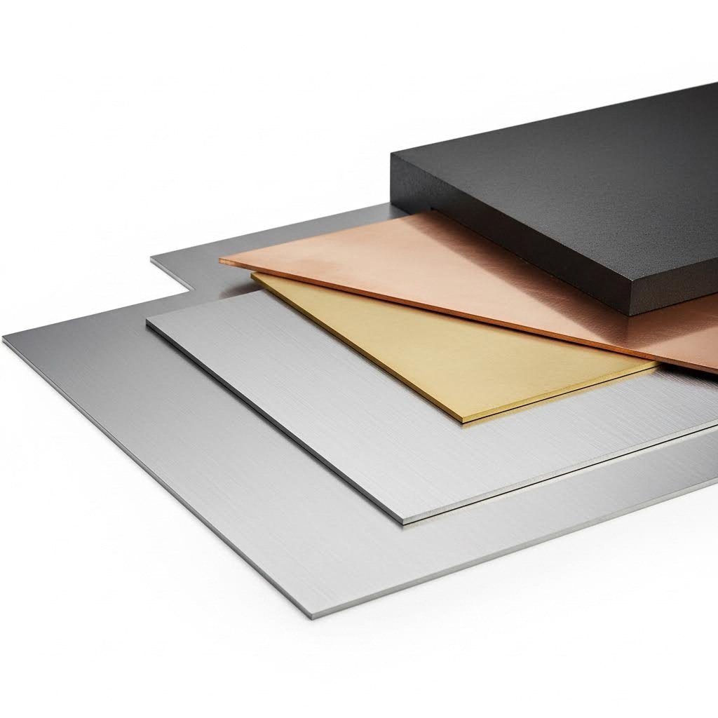
เหล็กคาร์บอนและเหล็กอ่อน: เป็นวัสดุที่ตัดได้ง่ายที่สุด เหล็กสามารถใช้ได้ดีกับทุกวิธีเกือบทุกชนิด การตัดด้วยเลเซอร์เหมาะอย่างยิ่งสำหรับการตัดแผ่นเหล็กบาง ในขณะที่พลาสมาจะโดดเด่นกว่าในแผ่นหนา ตาม คู่มือการตัดของ Longxin Laser , เลเซอร์ไฟเบอร์กำลัง 3 กิโลวัตต์สามารถตัดเหล็กกล้าคาร์บอนได้ถึงความหนา 22 มม. ทำให้เป็นทางเลือกที่นิยมสำหรับบริการตัดเหล็กส่วนใหญ่
เหล็กไม่ржаมี ปริมาณโครเมียมที่สูงขึ้นจะเพิ่มการสะท้อนแสง และต้องใช้พลังงานมากกว่าเหล็กกล้าคาร์บอน เลเซอร์ไฟเบอร์จัดการกับสแตนเลสได้อย่างมีประสิทธิภาพ แม้ว่าคุณจะต้องใช้พลังงานเพิ่มขึ้นประมาณ 20-30% เมื่อเทียบกับเหล็กอ่อนในความหนาเท่ากัน การตัดด้วยเจ็ทน้ำจะไม่เกิดโซนที่ได้รับผลกระทบจากความร้อนเลย ซึ่งเป็นสิ่งสำคัญสำหรับการใช้งานในอุตสาหกรรมอาหารหรือการแพทย์ที่ไม่สามารถยอมรับการเปลี่ยนแปลงโครงสร้างโลหะได้
อลูมิเนียม: โลหะเบาชนิดนี้มีความท้าทายในหลายเทคโนโลยี ความนำความร้อนสูงหมายถึงความร้อนจะสลายตัวอย่างรวดเร็ว จึงจำเป็นต้องตั้งค่าพลังงานสูงขึ้นสำหรับการตัดด้วยเลเซอร์ พื้นผิวอลูมิเนียมที่สะท้อนแสงอาจทำให้เลนส์ของเลเซอร์ CO2 เสียหาย ทำให้เลเซอร์ไฟเบอร์เป็นตัวเลือกที่ปลอดภัยกว่า สำหรับแผ่นอลูมิเนียมหนา การตัดด้วยเจ็ทน้ำมักเป็นทางเลือกที่เหมาะสมที่สุด เนื่องจากช่วยหลีกเลี่ยงปัญหาคราบสนิมที่มักเกิดขึ้นจากการตัดด้วยพลาสมา
ทองแดงและเหลืองทอง: โลหะสะท้อนแสงสูงเหล่านี้โดยประวัติศาสตร์แล้วมีปัญหาในการตัดด้วยเลเซอร์ เลเซอร์ไฟเบอร์กำลังสูงสมัยใหม่ (6 กิโลวัตต์ขึ้นไป) สามารถตัดทองแดงได้อย่างมีประสิทธิภาพ แม้ว่าคุณภาพของขอบจะต้องมีการปรับพารามิเตอร์อย่างระมัดระวัง ตามที่ 3ERP ระบุในการเปรียบเทียบการตัด พลาสมาคัตติ้งทำงานได้ดีกับทองเหลืองและทองแดง เนื่องจากทั้งสองชนิดนำไฟฟ้าได้ แต่การตัดด้วยน้ำแรงดันสูงยังคงเป็นทางเลือกชั้นหนึ่งสำหรับงานที่ต้องการไม่ให้เกิดการบิดตัวจากความร้อนเลย
โลหะผสมพิเศษ: ไทเทเนียม อินโคเนล และโลหะผสมประสิทธิภาพสูงอื่นๆ จำเป็นต้องพิจารณาเป็นพิเศษ ตาม คู่มือการผลิตของ Sintel การตัดด้วยน้ำแรงดันสูงเหมาะสำหรับไทเทเนียมและโลหะผสมอลูมิเนียมบางชนิดที่มีความไวต่อความร้อนเป็นสำคัญ วัสดุเหล่านี้มักต้องใช้วิธีการตัดแบบเย็นเพื่อรักษานิยามคุณสมบัติที่ออกแบบไว้
ช่วงความหนาและความจำกัด
ฟังดูซับซ้อนใช่ไหม? นี่คือความจริงในทางปฏิบัติ: ความหนาเป็นตัวกำหนดความเหมาะสมของวิธีการมากกว่าปัจจัยอื่นใด สิ่งที่ใช้งานได้ดีที่ 3 มม. อาจล้มเหลวโดยสิ้นเชิงที่ 25 มม.
อุตสาหกรรมแยกแยะออกเป็นสองประเภททั่วไป ได้แก่
- การตัดแผ่นโลหะ: โดยทั่วไปหมายถึง วัสดุที่มีความหนาน้อยกว่า 6 มม. (ประมาณ 1/4 นิ้ว) การตัดด้วยเลเซอร์เป็นที่นิยมในช่วงนี้ เนื่องจากมีข้อได้เปรียบด้านความเร็ว ความแม่นยำ และคุณภาพของขอบตัด
- การตัดแผ่นหนา: วัสดุที่มีความหนาตั้งแต่ 6 มม. ขึ้นไปจัดอยู่ในประเภทแผ่นหนา โดยระบบพลาสมาและระบบตัดด้วยน้ำจะมีความสามารถในการแข่งขันที่เพิ่มขึ้นเมื่อความหนาเพิ่มขึ้น ซึ่งระบบพลาสมามีข้อได้เปรียบด้านความเร็ว ขณะที่ระบบตัดด้วยน้ำให้คุณภาพผิวตัดที่ดีเยี่ยมโดยไม่มีผลจากความร้อน
กำลังเลเซอร์สัมพันธ์โดยตรงกับความสามารถในการตัดความหนา อ้างอิงจากข้อมูลจำเพาะของอุตสาหกรรมที่แสดงความแตกต่างอย่างชัดเจน:
- เลเซอร์ไฟเบอร์ 1.5 กิโลวัตต์: สามารถตัดเหล็กกล้าคาร์บอนได้ถึง 14 มม. เหล็กสเตนเลสได้ถึง 6 มม. และอลูมิเนียมได้ถึง 5 มม.
- เลเซอร์ไฟเบอร์ 6 กิโลวัตต์: สามารถตัดเหล็กกล้าคาร์บอนได้ถึง 25 มม. เหล็กสเตนเลสได้ถึง 16 มม. และอลูมิเนียมได้ถึง 16 มม.
- เลเซอร์ไฟเบอร์ 12 กิโลวัตต์+: เหล็กกล้าคาร์บอนถึง 40 มม. ขึ้นไป เหล็กสเตนเลสถึง 40 มม. อลูมิเนียมถึง 40 มม.
ตารางด้านล่างนี้ให้ข้อมูลอ้างอิงอย่างละเอียดในการจับคู่วัสดุกับวิธีการตัดตามความสามารถโดยทั่วไปของความหนา:
| ประเภทวัสดุ | วิธีหลักที่แนะนำ | วิธีทางเลือก | ความหนาสูงสุดโดยทั่วไป | ปัจจัยสำคัญที่ควรพิจารณา |
|---|---|---|---|---|
| เหล็กคาร์บอน/เหล็กอ่อน | เลเซอร์ไฟเบอร์ (บาง); พลาสมา (หนา) | วอเตอร์เจ็ท, การตัดด้วยเลื่อย | เลเซอร์: 40 มม.; พลาสมา: 50 มม. ขึ้นไป; วอเตอร์เจ็ท: 200 มม. ขึ้นไป | มีความยืดหยุ่นสูงสุด; สามารถใช้วิธีการทั้งหมดได้ดี |
| สแตนเลส | ไลเซอร์ไฟเบอร์ | ตัดด้วยเจ็ทน้ำ, พลาสมา | เลเซอร์: 40 มม.; เจ็ทน้ำ: 150 มม. ขึ้นไป | ต้องใช้กำลังเลเซอร์มากกว่าเหล็กคาร์บอนประมาณ 20-30% |
| อลูมิเนียม | เลเซอร์ไฟเบอร์ (บาง); เจ็ทน้ำ (หนา) | พลาสมา (มีข้อจำกัด) | เลเซอร์: 40 มม.; เจ็ทน้ำ: 200 มม. ขึ้นไป | นำความร้อนได้ดีมาก; หลีกเลี่ยงการใช้เลเซอร์ CO2 |
| ทองแดง | เจ็ทน้ำ; เลเซอร์ไฟเบอร์กำลังสูง (6 กิโลวัตต์ขึ้นไป) | พลาสม่า | เลเซอร์: 12 มม.; เจ็ทน้ำ: 100 มม. ขึ้นไป | สะท้อนแสงได้สูงมาก; ต้องใช้พารามิเตอร์พิเศษ |
| ทองเหลือง | เลเซอร์ไฟเบอร์; เวเตอร์เจ็ท | พลาสม่า | เลเซอร์: 16 มม.; เวเตอร์เจ็ท: 100 มม. ขึ้นไป | นำไฟฟ้าได้ดี รองรับพลาสมา; เลเซอร์เหมาะกว่าสำหรับความแม่นยำ |
| ไทเทเนียม | เจ็ทน้ำ | เลเซอร์ไฟเบอร์ (พร้อมระบบควบคุมก๊าซช่วยตัด) | เวเตอร์เจ็ท: 150 มม. ขึ้นไป; เลเซอร์: 25 มม. | ไวต่อความร้อน; เวเตอร์เจ็ทช่วยรักษาคุณสมบัติของวัสดุ |
| อินโคเนล/ซูเปอร์อัลลอย | เจ็ทน้ำ | EDM, เลเซอร์ไฟเบอร์ | เวเตอร์เจ็ท: 100 มม. ขึ้นไป | แข็งมาก; การตัดแบบเย็นช่วยป้องกันการเกิดฮาร์ดเดนนิ่งของผิววัสดุ |
คุณสมบัติของวัสดุที่มีผลต่อผลลัพธ์ของการตัด
นอกเหนือจากการเข้ากันได้เบื้องต้นแล้ว คุณสมบัติของวัสดุยังมีอิทธิพลต่อคุณภาพสุดท้ายในด้านต่างๆ ที่ส่งผลต่อความสำเร็จของโครงการของคุณ:
ความสามารถในการนําไฟฟ้า โลหะที่กระจายความร้อนได้อย่างรวดเร็ว (เช่น อลูมิเนียม ทองแดง) ต้องการค่าพลังงานที่สูงขึ้นหรือความเร็วที่ช้าลง สิ่งนี้มีผลต่อต้นทุนการตัดและคุณภาพของขอบตัด โลหะที่นำความร้อนได้ดีอาจแสดงโซนที่ได้รับผลกระทบจากความร้อนอย่างชัดเจนตามขอบตัดเมื่อใช้วิธีการตัดด้วยความร้อน
ความสะท้อน: โลหะที่มีความมันวาวสะท้อนพลังงานเลเซอร์กลับไปยังหัวตัด เลเซอร์ไฟเบอร์รุ่นใหม่สามารถจัดการกับปัญหานี้ได้ดีกว่าเทคโนโลยีรุ่นเก่า แต่ความสามารถในการสะท้อนยังคงมีความสำคัญต่อคุณภาพของขอบตัดและความเร็วในการตัดวัสดุ เช่น สเตนเลสผิวขัดมัน หรือทองแดง
ความแข็ง: เหล็กเครื่องมือและโลหะผสมที่ผ่านการอบแข็งทำให้การตัดด้วยวิธีเชิงกลเกิดความท้าทาย การสึกหรอของใบเลื่อยจะเพิ่มขึ้นอย่างมาก ส่งผลให้ต้นทุนต่อชิ้นเพิ่มสูงขึ้น วิธีการตัดด้วยความร้อนและวิธีไฮโดรเจ็ตมักจะคุ้มค่ามากกว่า แม้อัตราค่าบริการต่อชั่วโมงจะสูงกว่า
เมื่อกำหนดผลิตภัณฑ์ตัดโลหะสำหรับโครงการของคุณ ควรพิจารณาไม่เพียงแต่ว่าวิธีการนั้นสามารถตัดวัสดุของคุณได้หรือไม่ แต่ยังต้องพิจารณาด้วยว่าคุณสมบัติของวัสดุมีผลต่อผิวขอบ ความแม่นยำด้านมิติ และความต้องการในการแปรรูปขั้นที่สองอย่างไร ผู้รับจ้างผลิตที่เข้าใจความสัมพันธ์เหล่านี้สามารถแนะนำแนวทางที่คุ้มค่าที่สุดสำหรับการใช้งานเฉพาะของคุณได้
การเลือกวัสดุและความต้องการด้านความหนาเป็นสิ่งที่กำหนดสิ่งที่ทำได้ — แต่ค่าความคลาดเคลื่อนที่แม่นยำจะเป็นตัวกำหนดว่าผลลัพธ์จะตรงตามข้อกำหนดการใช้งานของคุณหรือไม่ การเข้าใจข้อกำหนดเกี่ยวกับค่าความคลาดเคลื่อนจะช่วยให้คุณหลีกเลี่ยงการระบุค่าที่สูงเกินไป (และจ่ายเงินมากเกินไป) ในขณะที่ยังคงมั่นใจได้ว่าชิ้นส่วนจะพอดีและทำงานได้ตามที่ออกแบบไว้
ค่าความคลาดเคลื่อนที่แม่นยำและมาตรฐานการควบคุมคุณภาพ
คุณได้เลือกวิธีการตัดและตรวจสอบความเข้ากันได้ของวัสดุแล้ว แต่คำถามต่อไปนี้คือสิ่งที่แบ่งแยกโครงการที่ประสบความสำเร็จออกจากงานที่ต้องแก้ไขใหม่ซึ่งมีค่าใช้จ่ายสูง: แอปพลิเคชันของคุณต้องการค่าความคลาดเคลื่อน (tolerance) เท่าใดในความเป็นจริง? ผู้ซื้อจำนวนมากกำหนดค่าความแม่นยำสูงเกินไป (จ่ายราคาพรีเมียมสำหรับความแม่นยำที่ไม่จำเป็น) หรือไม่ระบุให้ชัดเจนพอ (ได้รับชิ้นส่วนที่ไม่สามารถประกอบได้พอดี) การเข้าใจข้อกำหนดด้านค่าความคลาดเคลื่อนจะช่วยให้คุณตัดสินใจได้อย่างมีข้อมูล ซึ่งทำให้สามารถสร้างสมดุลระหว่างประสิทธิภาพและการใช้งบประมาณ
ในบริบทของการตัดโลหะ ความแม่นยำหมายถึงระดับความใกล้เคียงของขนาดที่ได้หลังการผลิตเทียบกับค่าเป้าหมายที่กำหนดไว้ เช่น เมื่อแบบแปลนกำหนดขนาด 100 มม. พร้อมค่าความคลาดเคลื่อน ±0.1 มม. ชิ้นงานที่ยอมรับได้ควรมีขนาดอยู่ระหว่าง 99.9 มม. ถึง 100.1 มม. แต่มีสิ่งหนึ่งที่ผู้รับจ้างผลิตมักไม่ค่อยอธิบาย นั่นคือเทคโนโลยีการตัดแต่ละประเภทสามารถบรรลุช่วงค่าความคลาดเคลื่อนที่แตกต่างกันมาก และความสามารถเหล่านี้มีผลโดยตรงต่อการเลือกวิธีการตัดของคุณ
ค่าความแม่นยำตามเทคโนโลยีการตัด
แต่ละวิธีการตัดมีข้อจำกัดด้านความแม่นยำในตัวเองซึ่งขึ้นอยู่กับหลักการทางฟิสิกส์ของวิธีนั้นๆ การตัดด้วยความร้อนจะก่อให้เกิดปัจจัยบิดเบือนจากความร้อน ส่วนวิธีเชิงกลเผชิญกับปัญหาการโก่งตัวและการสึกหรอของใบมีด การเข้าใจศักยภาพพื้นฐานเหล่านี้จะช่วยให้คุณเลือกเทคโนโลยีที่เหมาะสมกับข้อกำหนด ไม่ใช่ทำในทางกลับกัน
ตามการวิเคราะห์ช่วงความคลาดเคลื่อนในการกลึงของ Davantech ต่อไปนี้คือช่วงความคลาดเคลื่อนโดยทั่วไปตามแต่ละกระบวนการ
- กลึง CNC (3 แกน) ±0.05 มม. ถึง ±0.1 มม. — เหมาะมากสำหรับการใช้งานเครื่องตัดโลหะความแม่นยำสูงที่ต้องการควบคุมขนาดอย่างแน่นหนา
- CNC Turning: ±0.02 มม. ถึง ±0.05 มม. — ให้ความแม่นยำสูงเป็นพิเศษสำหรับชิ้นส่วนที่หมุนได้
- การกัดด้วยเครื่อง CNC แบบ 5 แกน: ±0.02 มม. หรือดีกว่า — ตัวเลือกระดับพรีเมียมสำหรับชิ้นงานเรขาคณิตที่ซับซ้อนในอุตสาหกรรมการบินและทางการแพทย์
- การตัดเลเซอร์: ±0.1 มม. ถึง ±0.2 มม. สำหรับงานทั่วไป; ระบบที่มีความแม่นยำสูงสามารถทำได้ถึง ±0.05 มม. กับวัสดุบาง
- การตัดไฮโดรเจ็ท: ±0.1 มม. ถึง ±0.25 มม. — ความแม่นยำที่น่าประทับใจ โดยไม่เกิดโซนที่ได้รับผลกระทบจากความร้อน
- การตัดพลาสมา: ±0.5 มม. ถึง ±1.5 มม. — เร็วที่สุดสำหรับวัสดุหนา แต่มีความแม่นยำต่ำกว่าวิธีอื่น
- การดัดแผ่นโลหะ: ±0.2 มม. ถึง ±0.5 มม. — การขึ้นรูปในขั้นตอนที่สองจะเพิ่มความคลาดเคลื่อนสะสม
- การขัด; ±0.002 มม. ถึง ±0.005 มม. — ใช้สำหรับกระบวนการตกแต่งขั้นสุดท้ายที่ต้องการความแม่นยำสูงพิเศษ
ข้อมูลอ้างอิงจากคู่มือความคลาดเคลื่อนของ Komacut ให้รายละเอียดเพิ่มเติมสำหรับงานโลหะแผ่น โดยผลการทดสอบของพวกเขาแสดงให้เห็นว่า การตัดด้วยเลเซอร์สามารถบรรลุความคลาดเคลื่อนเชิงเส้นที่ ±0.12 มม. สำหรับวัสดุที่มีความหนาตั้งแต่ 0.5 มม. ถึง 2 มม. และความคลาดเคลื่อนเส้นผ่านศูนย์กลางรูอยู่ที่ ±0.08 มม. ในสภาวะที่ต้องการความแม่นยำสูง
ตัวเลขเหล่านี้ชี้ให้เห็นข้อสังเกตสำคัญ: หากแอปพลิเคชันของคุณต้องการความคลาดเคลื่อนที่แคบกว่า ±0.1 มม. การตัดด้วยเลเซอร์เพียงอย่างเดียวอาจไม่เพียงพอ คุณอาจจำเป็นต้องใช้เครื่องจักรขั้นที่สอง การเจียร หรือกระบวนการหลักที่แตกต่างออกไปทั้งหมด บริษัทที่ให้บริการเครื่องมือครบวงจรมักรวมการตัดเข้ากับกระบวนการตกแต่งที่แม่นยำ เพื่อบรรลุข้อกำหนดที่ไม่สามารถทำได้ด้วยกระบวนการใดกระบวนการหนึ่งเพียงอย่างเดียว
เมื่อความแม่นยำสูงมีความสำคัญที่สุด
ไม่ใช่ทุกโครงการที่ต้องการค่าความคลาดเคลื่อนที่แคบมาก ลองนึกภาพว่าคุณกำลังผลิตแผงตกแต่ง — การเบี่ยงเบน ±0.5 มม. จะไม่ส่งผลต่อรูปลักษณ์หรือการใช้งาน แต่พิจารณาชิ้นส่วนที่รองรับเพลาแบริ่งซึ่ง ±0.02 มม. สามารถกำหนดได้ว่าชิ้นส่วนจะล็อกติดหรือหมุนได้อย่างอิสระ บริบทจึงเป็นตัวกำหนดข้อกำหนด
ค่าความคลาดเคลื่อนความแม่นยำสูงมีความสำคัญอย่างยิ่งในสถานการณ์เหล่านี้:
- ชิ้นส่วนประกอบที่ต้องเข้ากันได้: ชิ้นส่วนที่ออกแบบมาให้พอดีกันจำเป็นต้องมีค่าความคลาดเคลื่อนที่สอดคล้องกัน เช่น การต่อแบบแรงอัดอาจกำหนดให้เป็นแบบ H7/p6 ซึ่งต้องการการควบคุมระดับไมครอน
- ระบบการเคลื่อนไหว: รางเลื่อน แบริ่ง และชิ้นส่วนที่หมุนได้ จะทำให้ข้อผิดพลาดด้านมิติกลายเป็นปัญหาด้านประสิทธิภาพ
- อุปกรณ์ทางการแพทย์: ตามข้อกำหนดของอุตสาหกรรม อุปกรณ์ฝังในทางการแพทย์มักต้องการค่าความคลาดเคลื่อน ±0.005 มม. หรือดีกว่านั้น
- ส่วนประกอบการบินและอวกาศ: แอปพลิเคชันที่เกี่ยวข้องกับความปลอดภัยโดยทั่วไปจะกำหนดช่วงค่าความคลาดเคลื่อน ±0.005 มม. ถึง ±0.02 มม.
- ชิ้นส่วนออปติคัลและไมโครกลไก: ความแม่นยำจะอยู่ในระดับไมครอน (±0.001 มม. ถึง ±0.005 มม.) สำหรับการใช้งานเฉพาะทาง
นี่คือแนวทางปฏิบัติที่เป็นรูปธรรม: ระบุค่าความคลาดเคลื่อนที่หลวมที่สุดเท่าที่จะทำได้ แต่ยังคงตอบสนองความต้องการในการใช้งานได้ ค่าความคลาดเคลื่อนที่แคบลงมักจะมีต้นทุนสูงกว่าเสมอ—เนื่องจากต้องใช้ความเร็วในการตัดที่ช้าลง อุปกรณ์ยึดจับที่มั่นคงแข็งแรงมากขึ้น สภาพแวดล้อมที่ควบคุมอุณหภูมิ และใช้เวลานานขึ้นในขั้นตอนการตรวจสอบ เมื่อบริษัทบริการเครื่องมือคาร์ไบด์ จำกัด หรือผู้ให้บริการงานกลึงความแม่นยำรายอื่นๆ ทำการเสนอราคา ข้อกำหนดด้านค่าความคลาดเคลื่อนมักจะเป็นตัวแปรต้นทุนที่ใหญ่ที่สุด
กระบวนการควบคุมคุณภาพที่รับประกันความถูกต้องแม่นยำ
ค่าความแม่นยำทางเทคนิคไม่มีความหมายใดๆ หากไม่มีการตรวจสอบยืนยัน การวิเคราะห์การควบคุมคุณภาพของ Superior Manufacturing การประกันคุณภาพที่มีประสิทธิภาพ หมายถึง การตรวจสอบและยืนยันว่าผลิตภัณฑ์เป็นไปตามข้อกำหนดการออกแบบตลอดกระบวนการผลิต—ไม่ใช่เพียงแค่การตรวจสอบในขั้นตอนสุดท้าย
ผู้ผลิตมืออาชีพใช้วิธีการตรวจสอบหลายรูปแบบ:
- เครื่องวัดพิกัด (CMM): โพรบที่ควบคุมด้วยคอมพิวเตอร์ วัดรูปร่างเรขาคณิตสามมิติเทียบกับแบบจำลอง CAD เพื่อตรวจจับความเบี่ยงเบนด้วยความแม่นยำระดับไมครอน
- ออพติคอลคอมเพียเรเตอร์: ฉายภาพโปรไฟล์ชิ้นส่วนโครงการลงบนหน้าจอที่ได้รับการปรับเทียบเพื่อเปรียบเทียบทางสายตาเทียบกับช่วงค่าความคลาดเคลื่อน
- เกจวัดแบบ Go/No-go: เครื่องมือตรวจสอบแบบไบนารีอย่างง่ายสำหรับมิติที่สำคัญในการผลิตจำนวนมาก
- เครื่องวัดความหยาบของผิว: วัดค่า Ra (ค่าความหยาบเฉลี่ย) เพื่อยืนยันข้อกำหนดของพื้นผิวเรียบร้อย
- การควบคุมกระบวนการทางสถิติ (SPC): ติดตามแนวโน้มของมิติในแต่ละรอบการผลิต เพื่อตรวจจับการเบี่ยงเบนก่อนที่ชิ้นส่วนจะเกินขีดจำกัดความคลาดเคลื่อน
ความสำคัญของการรับรองมาตรฐาน ISO มีความจำเป็นอย่างยิ่งเมื่อความแม่นยำมีบทบาทสำคัญ การรับรอง ISO 9001 แสดงให้เห็นว่าผู้ผลิตมีระบบการจัดการคุณภาพที่จัดทำเป็นเอกสารและดำเนินการอย่างต่อเนื่อง สำหรับงานซ่อมเครื่องมือกลและงานที่ต้องการความแม่นยำสูง ควรเลือกผู้ผลิตที่สามารถจัดทำรายงาน CMM ได้ตามคำขอ และมีอุปกรณ์ตรวจสอบที่ได้รับการปรับเทียบอย่างเหมาะสม เช่นเดียวกับที่ผู้เชี่ยวชาญด้านคุณภาพได้ชี้แนะไว้ การทำงานกับผู้ผลิตที่มีประสบการณ์และเข้าใจค่าความคลาดเคลื่อนเฉพาะกระบวนการ จะส่งผลต่างอย่างมากต่อความแม่นยำและคุณภาพของชิ้นส่วน
ประเภทของวัสดุก็มีผลต่อค่าความคลาดเคลื่อนที่สามารถทำได้เช่นกัน โลหะที่นิ่มกว่า เช่น อลูมิเนียม สามารถกลึงให้มีค่าความคลาดเคลื่อนแคบได้ง่ายกว่าเหล็กที่ผ่านการอบแข็ง ผนังบางและรูปทรงเรขาคณิตที่ซับซ้อนอาจเกิดการโก่งตัวระหว่างการตัด ซึ่งจำกัดความแม่นยำที่สามารถทำได้ในทางปฏิบัติ การซ่อมแซมแม่พิมพ์และอุปกรณ์มักต้องการค่าความคลาดเคลื่อนที่สูงกว่าขีดจำกัดความสามารถของการตัดมาตรฐาน—จึงจำเป็นต้องใช้การเจียรหรือการตกแต่งด้วยกระบวนการ EDM
การเข้าใจขีดความสามารถด้านค่าความคลาดเคลื่อนจะช่วยให้คุณสื่อสารข้อกำหนดได้อย่างมีประสิทธิภาพ—แต่การแปลงข้อกำหนดเหล่านั้นให้กลายเป็นไฟล์ที่พร้อมสำหรับการผลิตนั้น ต้องอาศัยชุดข้อกำหนดอีกชุดหนึ่ง ซึ่งผู้รับจ้างผลิตส่วนใหญ่มักไม่ชี้แจงไว้ล่วงหน้า
วิธีเตรียมโครงการตัดโลหะของคุณ
คุณได้เลือกวิธีการตัด ตรวจสอบความเข้ากันได้ของวัสดุ และระบุค่าความคลาดเคลื่อนแล้ว แต่นี่คือจุดที่โครงการจำนวนมากหยุดชะงัก: การจัดเตรียมไฟล์ ในการส่งไฟล์ออกแบบที่จัดรูปแบบไม่เหมาะสม อาจทำให้การขอใบเสนอราคาล่าช้าไปหลายวัน ก่อให้เกิดข้อผิดพลาดที่สิ้นเปลืองวัสดุราคาแพง หรือผลิตชิ้นงานที่ไม่ตรงตามวัตถุประสงค์ของคุณ อย่างไรก็ตาม ผู้รับจ้างผลิตส่วนใหญ่มักจะระบุเพียงแค่รูปแบบไฟล์ที่ยอมรับ โดยไม่ได้อธิบายว่าอะไรคือองค์ประกอบที่ทำให้ไฟล์พร้อมสำหรับการผลิต
ความจริงก็คือ ไฟล์ดิจิทัลของคุณทำหน้าที่เป็นแบบแปลนการผลิต เส้นทุกเส้น มิติทุกมิติ และเลเยอร์ทุกชั้น จะถูกแปลงโดยตรงไปเป็นคำสั่งเครื่องจักร การทำความเข้าใจข้อกำหนดของไฟล์และปัจจัยพิจารณาด้านการออกแบบตั้งแต่ต้น จะช่วยลดการแก้ไขซ้ำซากที่สร้างความหงุดหงิดใจให้ทั้งวิศวกรและผู้รับจ้างผลิต
รูปแบบไฟล์และข้อกำหนดการออกแบบ
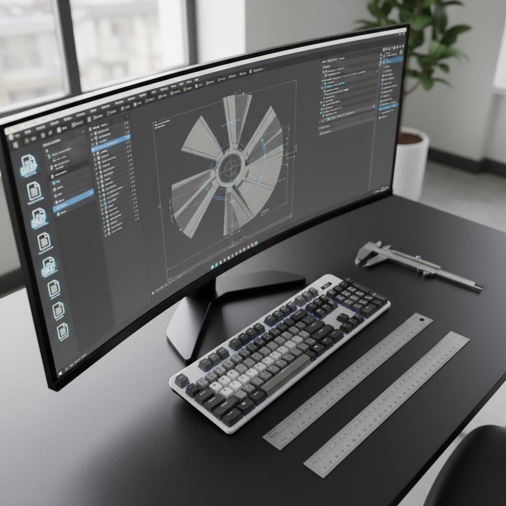
เมื่อคุณส่งโปรเจกต์สำหรับการตัดโลหะ ซอฟต์แวร์ของผู้รับจ้างผลิตจะต้องตีความการออกแบบของคุณและแปลงเป็นรหัสที่เครื่องจักรสามารถอ่านได้ รูปแบบไฟล์ต่าง ๆ จะให้ข้อมูลที่แตกต่างกันไป และการเลือกรูปแบบที่ไม่เหมาะสมอาจทำให้ข้อมูลสำคัญหายไป
รูปแบบที่นิยมใช้กันทั่วไป:
- DXF (Drawing Exchange Format): มาตรฐานสากลสำหรับเส้นทางการตัดแบบ 2 มิติ ตาม คู่มือการเตรียมงานของ Datum Alloys ไฟล์ DXF ควรมีภาพวาด 2 มิติที่สะอาด ไม่มีกล่องชื่อเรื่อง เส้นบอกขนาด หรือโน้ตเพิ่มเติม หนึ่งชิ้นงานต่อหนึ่งไฟล์ โดยไม่มีรูปทรงซ้อนทับหรือซ้ำกัน
- DWG (AutoCAD Drawing): รูปแบบต้นฉบับของ AutoCAD ที่ให้ข้อมูลเวกเตอร์ 2 มิติในลักษณะเดียวกับ DXF โปรดตรวจสอบว่าคุณส่งเฉพาะเรขาคณิตของภาพวาดเท่านั้น ไม่ใช่ข้อมูลโมเดล 3 มิติที่ต้องแปลงรูปแบบ
- STEP (Standard for the Exchange of Product Data): รูปแบบที่แนะนำสำหรับชิ้นส่วน 3 มิติที่ต้องการกลึงด้วยเครื่อง CNC ไฟล์ STEP เก็บรักษาเรขาคณิตแบบของแข็งไว้ได้ ทำให้ผู้รับจ้างผลิตสามารถดึงเส้นทางการตัดและตรวจสอบความสามารถในการผลิตได้
- แบบแปลน PDF: มีประโยชน์เป็นเอกสารประกอบที่แสดงขนาด ค่าความคลาดเคลื่อน และหมายเหตุ แต่ไม่เหมาะสำหรับการเขียนโปรแกรมเครื่องโดยตรง ควรแนบไฟล์ PDF พร้อมกับไฟล์เวกเตอร์เพื่อการสื่อสารที่สมบูรณ์
กฎสำคัญสำหรับการเตรียมไฟล์:
ฟังดูง่ายใช่ไหม? นี่คือจุดที่โครงการมักจะล้มเหลว:
- แปลงข้อความเป็นเส้นรอบรูป: กล่องข้อความที่ยังคงใช้งานอยู่ในซอฟต์แวร์ออกแบบของคุณจะไม่ถูกแปลงเป็นเส้นตัด อินเดียสตริเตอร์ ให้ใช้คำสั่ง "convert to outlines" ในโปรแกรม CAD ให้มองหาคำสั่ง "explode" หรือ "expand" หากคุณยังสามารถคลิกและแก้ไขข้อความได้ แสดงว่าข้อความนั้นยังต้องแปลง
- ตรวจสอบให้แน่ใจว่าเส้นทางเชื่อมต่ออย่างต่อเนื่อง: เส้นตัดทั้งหมดต้องสมบูรณ์และไม่ขาดตอน เส้นประ เส้นที่หัก หรือช่องว่างจำเป็นต้องทำความสะอาดก่อนการตัด เลเซอร์และเครื่องตัดน้ำยาจะทำตามเส้นเวกเตอร์แบบต่อเนื่อง—ไม่สามารถตีความประเภทเส้นที่ตกแต่งพิเศษได้
- ส่งออกไฟล์ในมาตราส่วน 1:1: ส่งไฟล์เสมอในขนาดจริงตามที่เป็น ตามที่เน้นโดยแนวทางปฏิบัติที่ดีที่สุดในอุตสาหกรรม การไม่ตรงกันของมาตราส่วนจะทำให้ชิ้นงานถูกตัดเล็กหรือใหญ่เกินไป ให้พิมพ์แบบออกแบบของคุณที่มาตราส่วน 100% เพื่อยืนยันขนาดก่อนส่ง
- กำจัดข้อมูลซ้ำและซ้อนทับกัน: เรขาคณิตที่ทับซ้อนกันจะทำให้เครื่องตัดเส้นทางเดียวกันสองครั้ง ส่งผลให้ขอบเสียหายและสิ้นเปลืองเวลา โปรดตรวจสอบเส้นที่ซ้อนกันหรือองค์ประกอบที่คัดลอกมาแล้วอยู่ในตำแหน่งเดียวกันพอดี
- ลบช่องตัดลอยตัว: รูปร่างภายในที่ไม่ได้เชื่อมต่อกับชิ้นส่วนหลักจะหลุดออกไปขณะการตัด ควรส่งออกแบบเหล่านี้แยกต่างหาก หรือเพิ่มแท็บยึดเพื่อคงอยู่ระหว่างการตัด
หากคุณแปลงไฟล์จากรูปภาพแรสเตอร์ (JPG, PNG, BMP) โปรดตรวจสอบขนาดทั้งหมดอย่างละเอียด การแปลงจากรูปภาพแรสเตอร์เป็นเวกเตอร์มักทำให้เกิดความผิดพลาดในการปรับสเกลหรือเส้นโค้งที่ประมาณค่า ซึ่งอาจไม่ตรงกับต้นฉบับของคุณ
การเตรียมโปรเจกต์สำหรับการตัดโลหะ
นอกเหนือจากการจัดรูปแบบไฟล์ การเตรียมโปรเจกต์ให้สมบูรณ์ยังรวมถึงการปรับแต่งการออกแบบและการสื่อสารอย่างชัดเจน การปฏิบัติตามขั้นตอนการเตรียมงานอย่างเป็นระบบจะช่วยป้องกันการแก้ไขที่เสียค่าใช้จ่าย และเร่งกระบวนการผลิต
- สรุปการเลือกวัสดุและความหนา ยืนยันประเภทวัสดุ ระดับเกรด ความหนา และข้อกำหนดพื้นผิวใดๆ ก่อนสร้างแบบแปลนสุดท้าย พารามิเตอร์การตัดจะแตกต่างกันไปตามวัสดุ—การเปลี่ยนข้อกำหนดหลังจากส่งเอกสารแล้ว มักจำเป็นต้องมีการประเมินราคาใหม่ทั้งหมด
- ตรวจสอบรูปทรงเรขาคณิตเพื่อความเหมาะสมในการผลิต: ตรวจสอบว่ามุมภายในมีรัศมีที่เหมาะสมสำหรับวิธีการตัดของคุณหรือไม่ ตามที่ คู่มือวิศวกรรม DFM ของ Modus Advanced ระบุว่า มุมภายในที่คมต้องใช้อุปกรณ์พิเศษ และทำให้เวลาโปรแกรมเพิ่มขึ้น 50-100% ควรระบุรัศมีที่ใหญ่ที่สุดซึ่งการออกแบบของคุณสามารถรองรับได้
- ตรวจสอบขนาดของรายละเอียดขั้นต่ำ: เทคโนโลยีการตัดแต่ละชนิดมีขนาดเส้นผ่านศูนย์กลางรู ความกว้างช่อง และขนาดรายละเอียดขั้นต่ำที่สามารถผลิตได้อย่างเชื่อถือได้ รายละเอียดที่เล็กเกินไปสำหรับกระบวนการที่เลือกไว้อาจทำให้ตัดไม่สำเร็จหรือได้คุณภาพขอบที่ไม่ดี ดังที่กล่าวไว้ในแนวทางของ SendCutSend รายละเอียดที่ต่ำกว่าเกณฑ์ขั้นต่ำอาจไม่ถูกคงไว้
- สร้างไฟล์เวกเตอร์ที่สะอาด: ส่งออกแบบของคุณในรูปแบบที่รองรับ (DXF, DWG หรือ STEP) ตามกฎการจัดรูปแบบข้างต้น ใช้เครื่องมือทำความสะอาดเส้นทางเพื่อกำจัดรายการซ้ำ และตรวจสอบเรขาคณิตให้ต่อเนื่อง
- จัดทำเอกสารประกอบเพิ่มเติม: รวมภาพวาด PDF ที่ระบุขนาด แสดงค่าความคลาดเคลื่อนที่สำคัญ การระบุพื้นผิวสำเร็จรูป และข้อกำหนดพิเศษใด ๆ ระบุลักษณะที่สำคัญที่สุดต่อการทำงาน
- ระบุกระบวนการรอง: หากชิ้นส่วนของคุณต้องการการดัด การเชื่อม การพ่นผง หรือกระบวนการอื่นหลังการตัด ให้แจ้งความต้องการเหล่านี้แต่เนิ่น ๆ การดำเนินการรองจะส่งผลต่อแนวทางการตัด เช่น ชิ้นส่วนที่ต้องการดัดอาจต้องการทิศทางเม็ดผลึกเฉพาะ
- ส่งและตรวจสอบใบเสนอราคา: เมื่อคุณได้รับใบเสนอราคา ให้ตรวจสอบว่าผู้รับจ้างได้ตีความข้อกำหนดของคุณอย่างถูกต้อง ยืนยันวัสดุ ปริมาณ ค่าความคลาดเคลื่อน และข้อเสนอแนะ DFM ก่อนอนุมัติการผลิต
การสนับสนุน DFM ช่วยป้องกันข้อผิดพลาดที่ส่งผลกระทบต่อต้นทุนได้อย่างไร
การออกแบบเพื่อความสามารถในการผลิต (DFM) ถือเป็นแนวทางแบบระบบเพื่อปรับแต่งชิ้นส่วนให้เหมาะสมต่อการผลิตอย่างมีประสิทธิภาพ ตามงานวิจัยด้านวิศวกรรมการผลิต การนำ DFM ไปใช้อย่างมีประสิทธิภาพสามารถลดต้นทุนการผลิตได้ 15-40% และลดระยะเวลาการผลิตได้ 25-60% เมื่อเทียบกับการออกแบบที่ไม่ได้รับการปรับแต่ง
การสนับสนุน DFM อย่างครอบคลุมจากผู้ผลิตจะช่วยระบุปัญหาที่อาจเกิดขึ้นก่อนเริ่มการผลิต:
- ความขัดแย้งของรูปทรงเรขาคณิต: ลักษณะต่างๆ ที่ไม่สามารถผลิตได้ด้วยวิธีการที่เลือก เช่น มุมภายในที่แหลมคมในการตัดด้วยเลเซอร์ หรือร่องเว้าในกระบวนการกลึงแบบตั้งค่าเดียว
- การคาดคะเนความอดทน: เมื่อมีการกำหนดค่าทอลเลอร์แรนซ์ที่แคบหลายตำแหน่งรวมกันบนชิ้นส่วนเดียวกัน อาจทำให้การบรรลุตามข้อกำหนดทั้งหมดพร้อมกันเป็นไปได้ยาก
- การเพิ่มประสิทธิภาพการใช้วัสดุให้เกิดของเสียน้อยที่สุด: การจัดเรียงชิ้นส่วนอย่างมีประสิทธิภาพบนแผ่นวัสดุจะช่วยลดการใช้วัสดุและต้นทุนต่อชิ้น
- คำแนะนำในการเลือกกระบวนการผลิต: แนะนำวิธีการทางเลือกเมื่อทางเลือกเริ่มต้นของคุณก่อให้เกิดความซับซ้อนหรือต้นทุนที่ไม่จำเป็น
ผู้รับจ้างผลิตที่ให้บริการซ่อมบำรุงเครื่องมือกลและบริการซ่อมเครื่อง CNC มักมีความรู้เชิงลึกเกี่ยวกับกระบวนการผลิตมากกว่าในการตรวจสอบ DFM พวกเขาเข้าใจว่าขีดความสามารถของอุปกรณ์ ข้อจำกัดของเครื่องมือ และข้อกำหนดในการตั้งค่าส่งผลต่อสิ่งที่สามารถทำได้จริงอย่างไร ซึ่งเป็นข้อมูลเชิงลึกที่วิศวกรออกแบบเพียงอย่างเดียวอาจขาดไป
เมื่อพิจารณาผู้รับจ้างผลิต ควรถามว่าพวกเขาให้ข้อเสนอแนะ DFM เป็นส่วนหนึ่งของกระบวนการเสนอราคาหรือไม่ โดยผู้ให้บริการที่มีบริการเจียรกรอบมีดหรือบริการเครื่องมือคาร์ไบด์ มักมีผู้เชี่ยวชาญภายในองค์กร ซึ่งจะช่วยให้การทบทวนการออกแบบละเอียดลึกซึ้งมากขึ้น การลงทุนล่วงหน้าในเรื่องการสื่อสารนี้จะช่วยป้องกันการแก้ไขงานซ้ำที่ทำให้โครงการล่าช้าและทำให้งบประมาณเพิ่มสูงขึ้น
เมื่อไฟล์ของคุณพร้อมและแบบแปลนถูกปรับแต่งแล้ว สิ่งที่ควรพิจารณาต่อไปคือการประยุกต์ใช้หลักการเหล่านี้ในอุตสาหกรรมต่างๆ เพราะชิ้นส่วนอากาศยาน ชิ้นส่วนยานยนต์ และองค์ประกอบการก่อสร้าง แต่ละประเภทมีข้อกำหนดเฉพาะตัวที่แตกต่างกัน ซึ่งส่งผลต่อการเลือกผู้รับจ้างผลิต
การประยุกต์ใช้ในอุตสาหกรรมและความต้องการเฉพาะตามภาคส่วน
นี่คือความจริงที่ต้องพิจารณา: แผ่นสแตนเลสหนา 6 มม. ชิ้นเดียวกันที่ถูกตัดให้มีขนาดเท่ากัน อาจผ่านการตรวจสอบคุณภาพสำหรับโครงการอุปกรณ์ร้านอาหาร แต่กลับล้มเหลวอย่างรุนแรงเมื่อนำไปใช้กับชิ้นส่วนยึดในอุตสาหกรรมการบินและอวกาศ เหตุใดจึงเป็นเช่นนั้น? เพราะแต่ละอุตสาหกรรมมีข้อกำหนดที่แตกต่างกันอย่างมากเกินกว่าเพียงแค่ความแม่นยำของมิติ ใบรับรองวัสดุ เอกสารการติดตามที่มา และค่าความคลาดเคลื่อนเฉพาะทาง ล้วนมีความแตกต่างกันอย่างมากระหว่างภาคส่วน ดังนั้นความสามารถของผู้ผลิตชิ้นส่วนจะต้องสอดคล้องกับความคาดหวังของอุตสาหกรรมของคุณ
การเข้าใจข้อกำหนดเฉพาะด้านอุตสาหกรรมนี้ จะช่วยให้คุณสามารถตั้งคำถามที่เหมาะสมก่อนตัดสินใจเลือกผู้ให้บริการ ไม่ว่าคุณจะกำลังจัดหาชิ้นส่วนจากศูนย์กลางการขึ้นรูปโลหะในซินซินนาติ หรือสำรวจผู้เชี่ยวชาญด้านการตัดโลหะในเพิร์ธทั่วโลก กรอบการทำงานด้านการรับรองก็ยังคงเหมือนเดิมภายในแต่ละอุตสาหกรรม
ข้อกำหนดสำหรับชิ้นส่วนในอุตสาหกรรมการบินและอวกาศ รวมถึงยานยนต์
เมื่อชิ้นส่วนเหล่านั้นมีบทบาทโดยตรงต่อการรักษาชีวิตผู้คน ไม่ว่าจะเป็นในอากาศยานที่บินอยู่บนความสูง 35,000 ฟุต หรือยานพาหนะที่กำลังเคลื่อนที่ด้วยความเร็วบนทางหลวง มาตรฐานด้านคุณภาพก็จะเพิ่มระดับขึ้นอย่างมาก ทั้งภาคอุตสาหกรรมการบินและยานยนต์ได้พัฒนาระบบการรับรองที่เข้มงวด เพื่อกำกับดูแลทุกด้านของการตัดและแปรรูปโลหะ
ข้อกำหนดสำหรับอุตสาหกรรมการบินและอวกาศ:
การผลิตในอุตสาหกรรมการบินดำเนินการภายใต้การรับรองมาตรฐาน AS9100 ซึ่งพัฒนามาจาก ISO 9001 โดยมีข้อกำหนดเพิ่มเติมเฉพาะสำหรับการใช้งานที่เกี่ยวข้องกับการบินที่ต้องอาศัยความปลอดภัยสูงสุด ตาม การวิเคราะห์ความสอดคล้องด้านการบินของ Dynamic Metals ระบบนี้ถือเป็นระบบบริหารคุณภาพที่เข้มงวดและเข้มข้นกว่ามาตรฐานทั่วไปอย่างมาก
- การตรวจสอบแหล่งที่มาของวัสดุอย่างครบถ้วน: ต้องมีการติดตามโลหะทุกชิ้นตั้งแต่มาถึงจนกระทั่งส่งมอบขั้นสุดท้าย เมื่อลูกค้าร้องขอข้อมูลเกี่ยวกับล็อตอะลูมิเนียมบางล็อตในเวลาหกเดือนหลังการส่งมอบ เอกสารต้องรวมถึงบันทึกการอบความร้อน ใบรับรองการวิเคราะห์องค์ประกอบทางเคมี และผลการทดสอบเชิงกายภาพ
- ข้อกำหนดสำหรับผู้จัดจำหน่ายที่ได้รับการรับรอง: วัตถุดิบต้องมาจากผู้จัดจำหน่ายที่ได้รับการอนุมัติและมีมาตรฐานสำหรับอุตสาหกรรมการบิน โดยต้องมีระบบการรับรองคุณภาพของตนเอง การนี้ไม่ใช่แค่การซื้อจากผู้ขายที่มีชื่อเสียงเท่านั้น แต่ต้องมีเอกสารรับรองสถานะการรับรองมาพร้อมกับวัตถุดิบทุกล็อต
- การเก็บรักษาเอกสารเป็นเวลานาน ให้เก็บบันทึกคุณภาพทั้งหมดไว้อย่างน้อยเจ็ดปี ลูกค้าบางรายในอุตสาหกรรมการบินอาจกำหนดระยะเวลาการเก็บรักษานานกว่านั้น โดยเฉพาะอย่างยิ่งสำหรับชิ้นส่วนที่สำคัญต่อการบิน
- ระเบียบการทดสอบที่ครอบคลุม: การทดสอบจะต้องดำเนินการมากกว่าการตรวจสอบความแข็งแรงขั้นพื้นฐาน โดยรวมถึงการตรวจสอบขนาดพิเศษ การวิเคราะห์ทางโลหะวิทยา และการตรวจสอบแบบไม่ทำลาย โดยใช้อุปกรณ์ที่ได้รับการสอบเทียบและดำเนินการโดยบุคลากรที่ผ่านการฝึกอบรม
- ระบบบริหารจัดการความเสี่ยง AS9100 เน้นการป้องกันมากกว่าการแก้ไข ผู้ผลิตจำเป็นต้องดูแลระบบเพื่อระบุความล้มเหลวที่อาจเกิดขึ้น ประเมินความเสี่ยง และดำเนินมาตรการป้องกันก่อนที่ปัญหาจะเกิดขึ้น
กระบวนการรับรองในอุตสาหกรรมการบินและอวกาศมักใช้เวลา 12-18 เดือนสำหรับการเตรียมการ อุปสรรคทั่วไป ได้แก่ ระบบเอกสารไม่สมบูรณ์ ขั้นตอนการสืบค้นย้อนกลับไม่เพียงพอ และประวัติการฝึกอบรมพนักงานไม่เพียงพอ
ข้อกำหนดของอุตสาหกรรมยานยนต์:
อุตสาหกรรมยานยนต์อาศัยการรับรอง IATF 16949 ซึ่งเป็นกรอบการจัดการคุณภาพที่พัฒนาโดยคณะทำงานด้านยานยนต์ระหว่างประเทศ (International Automotive Task Force) ตามภาพรวมการรับรองของ Xometry มาตรฐานนี้สรุปข้อมูลจาก ISO 9001 ให้กลายเป็นแนวทางที่ออกแบบมาโดยเฉพาะสำหรับผู้ผลิตยานยนต์และห่วงโซ่อุปทานของพวกเขา
- เน้นการลดข้อบกพร่อง: การรับรอง IATF 16949 แสดงให้เห็นว่าองค์กรจำกัดข้อบกพร่องในผลิตภัณฑ์ ขณะเดียวกันก็ลดของเสียและแรงงานที่สูญเปล่า ซึ่งไม่ใช่แค่การตรวจพบปัญหาเท่านั้น แต่หมายถึงการป้องกันปัญหาอย่างเป็นระบบ
- สถานะการรับรองแบบไบนารี: ต่างจากระบบที่แบ่งระดับ IATF 16949 มีสถานะการรับรองแบบไบนารี กล่าวคือ บริษัทจะได้รับการรับรองหรือไม่ได้รับการรับรองเท่านั้น ไม่มีระดับความสอดคล้องบางส่วน
- การผสานรวมห่วงโซ่อุปทาน: ซัพพลายเออร์ ผู้รับเหมา และลูกค้าตลอดห่วงโซ่อุปทานในอุตสาหกรรมยานยนต์ ต่างต้องการใบรับรอง IATF 16949 เพิ่มมากขึ้น โดยหากไม่มีการรับรองนี้ โอกาสในการร่วมงานจะลดลงอย่างมาก
- การตรวจสอบภายในและภายนอก: กระบวนการรับรองประกอบด้วยการตรวจสอบภายในและการตรวจสอบภายนอก ครอบคลุมบริบทขององค์กร ผู้นำ การวางแผน ระบบสนับสนุน การดำเนินงาน การประเมินผลการปฏิบัติงาน และกระบวนการปรับปรุง
- ข้อกำหนดการปรับปรุงอย่างต่อเนื่อง: นอกเหนือจากการรับรองเบื้องต้น ผู้ผลิตจะต้องแสดงให้เห็นถึงการปรับปรุงอย่างต่อเนื่องในด้านตัวชี้วัดคุณภาพ อัตราความผิดพลาด และประสิทธิภาพของกระบวนการ
สำหรับผู้ผลิตที่ใช้เลเซอร์ตัดความแม่นยำในซินซินนาติ และผู้เชี่ยวชาญด้านโลหะแผ่นในซินซินนาติที่ให้บริการลูกค้าอุตสาหกรรมยานยนต์ การได้รับใบรับรอง IATF 16949 มักเป็นตัวกำหนดว่าพวกเขาจะสามารถแข่งขันเพื่อขอสัญญาได้หรือไม่ การลงทุนในโครงสร้างพื้นฐานการรับรองจะคุ้มค่าเมื่อได้รับโอกาสเข้าสู่ห่วงโซ่อุปทานยานยนต์รายใหญ่
การประยุกต์ใช้ในงานก่อสร้างและโครงสร้าง
การก่อสร้างและการผลิตโครงสร้างทำงานภายใต้กรอบคุณภาพที่แตกต่างกัน แต่มีความสำคัญเท่าเทียมกัน แม้ค่าความคลาดเคลื่อนอาจผ่อนปรนกว่าข้อกำหนดในอุตสาหกรรมการบินและอวกาศ แต่ผลกระทบด้านความปลอดภัยยังคงมีความสำคัญอย่างยิ่ง การล้มเหลวของโครงสร้างสามารถคร่าชีวิตและก่อให้เกิดความรับผิดทางกฎหมายจำนวนมาก
ข้อกำหนดสำหรับเหล็กโครงสร้าง:
ตามสถาบันเหล็กก่อสร้างแห่งอเมริกา (AISC) การตัดเหล็กก่อสร้างจะต้องเป็นไปตามมาตรฐานคุณภาพพื้นผิวที่เฉพาะเจาะจง ขึ้นอยู่กับการใช้งาน:
- ขอบที่ตัดด้วยความร้อนภายใต้แรงดึง: พื้นผิวควรจะมีค่าความหยาบไม่เกิน 1,000 ไมโครนิ้ว ตามที่กำหนดไว้ใน ASME B46.1 ขอบเหล่านี้ได้รับแรงกระทำสูงสุด และต้องการพื้นผิวเรียบที่สุด
- การตัดด้วยความร้อนแบบนำทางเชิงกล: ขอบที่ไม่ได้อยู่ภายใต้แรงดึงที่คำนวณไว้ ต้องมีค่าความหยาบไม่เกิน 2,000 ไมโครนิ้ว—ซึ่งยังคงเข้มงวด แต่คำนึงถึงระดับแรงกระทำที่ต่ำกว่า
- การตัดด้วยความร้อนแบบควบคุมด้วยมือ: สำหรับขอบที่ไม่ได้รับแรงเครียด การตัดด้วยมืออาจทำให้เกิดความหยาบได้สูงสุดถึง 1/16 นิ้ว ซึ่งผ่อนปรนกว่าการตัดด้วยเครื่องจักรอย่างมีนัยสำคัญ
- ข้อจำกัดของรอยเว้าและร่องลึก ขอบที่ตัดด้วยความร้อนทุกชนิดจะต้องปราศจากรอยเว้า และควรปราศจากร่องลึกโดยทั่วไป อนุญาตให้มีร่องลึกเป็นครั้งคราวได้ลึกไม่เกิน 3/16 นิ้ว แต่ข้อบกพร่องที่ลึกกว่านี้จำเป็นต้องได้รับการซ่อมแซมด้วยการเชื่อมตามขั้นตอนเฉพาะ
ข้อกำหนดของข้อต่อแบบอัด
ข้อกำหนด AISC กำหนดให้ข้อต่อแบบอัดที่พึ่งพาการรับแรงจากการสัมผัส จะต้องมีพื้นผิวที่เตรียมไว้ด้วยกระบวนการกัด มิลลิ่ง เลื่อย หรือวิธีอื่นที่เหมาะสม สิ่งสำคัญคือ กระบวนการเลื่อยด้วยแรงเสียดทาน (friction sawing) และการเลื่อยแบบเย็น (cold sawing) สามารถทำให้ได้ค่าความหยาบผิวไม่เกิน 500 ไมโครนิ้ว ซึ่งเป็นไปตามข้อกำหนด แสดงให้เห็นว่าอุปกรณ์เลื่อยแบบเย็นสามารถผลิตชิ้นงานที่ตัดได้อย่างสมบูรณ์และเพียงพอสำหรับการใช้งานในโครงสร้าง
มาตรฐานมุมกลับด้าน (Reentrant Corner)
การตัดช่องโครงสร้างต้องมีการเปลี่ยนผ่านอย่างเรียบเนียนที่มุมเว้า โดย AISC แนะนำรัศมีขั้นต่ำประมาณ ½ นิ้ว โดยเน้นเป็นพิเศษให้หลีกเลี่ยงการตัดมุมฉากซึ่งจะทำให้เกิดความเครียดสะสม สามารถสร้างการเปลี่ยนผ่านด้วยรัศมีได้โดยการเจาะรูโดยใช้ขนาดสว่านมาตรฐานที่ไม่น้อยกว่า ¾ นิ้ว
- ความสอดคล้องตาม AWS D1.1: การซ่อมแซมด้วยการเชื่อมเพื่อแก้ไขข้อบกพร่องจากการตัด ต้องปฏิบัติตามข้อกำหนดที่เกี่ยวข้องจาก AWS D1.1/D1.1M รวมถึงการใช้อิเล็กโทรดชนิดต่ำไฮโดรเจนที่มีเส้นผ่านศูนย์กลางไม่เกิน 5/32 นิ้ว
- ข้อกำหนดใบรับรองโรงงาน: เอกสารรับรองวัสดุที่ระบุองค์ประกอบทางเคมีและคุณสมบัติทางกลไก ต้องแนบมากับเหล็กโครงสร้างตลอดกระบวนการผลิต
- การตรวจสอบและการทดสอบ: การตรวจสอบด้วยสายตา การตรวจสอบมิติ และบางครั้งการทดสอบแบบไม่ทำลาย เพื่อยืนยันว่าชิ้นส่วนที่ผลิตแล้วเป็นไปตามข้อกำหนดการออกแบบ
ข้อพิจารณาทั่วไปในการผลิต
นอกเหนือจากข้อกำหนดเฉพาะในอุตสาหกรรมการบินและอวกาศ ยานยนต์ และการก่อสร้าง แล้ว แอปพลิเคชันการผลิตทั่วไปยังคงได้รับประโยชน์จากการดำเนินงานด้านคุณภาพอย่างเป็นระบบ
- มาตรฐาน ISO 9001 พื้นฐาน: แม้ไม่มีใบรับรองเฉพาะอุตสาหกรรม การได้รับมาตรฐาน ISO 9001 ก็แสดงให้เห็นว่าผู้ผลิตมีระบบการจัดการคุณภาพที่เป็นเอกสารอย่างชัดเจน และดำเนินงานตามกระบวนการที่สอดคล้องกัน
- ระดับการรับรองวัสดุ: ขอรายงานการทดสอบจากโรงงาน (MTRs) ที่เหมาะสม เพื่อยืนยันคุณสมบัติของวัสดุ — สิ่งจำเป็นสำหรับการใช้งานทุกประเภทที่ต้องพิจารณาคุณภาพของวัสดุ
- การตรวจสอบชิ้นงานตัวอย่างแรก (First Article Inspection): สำหรับการผลิตจริง ต้องการการตรวจสอบตัวอย่างชิ้นแรกที่มีเอกสารยืนยัน เพื่อยืนยันว่าชิ้นส่วนเบื้องต้นสอดคล้องกับข้อกำหนดทั้งหมด ก่อนเริ่มการผลิตเต็มรูปแบบ
- การควบคุมกระบวนการทางสถิติ: การผลิตต่อเนื่องจะได้รับประโยชน์จากการตรวจสอบ SPC ซึ่งสามารถตรวจจับความเบี่ยงเบนของกระบวนการก่อนที่ชิ้นส่วนจะเกินขีดจำกัดความคลาดเคลื่อน
เมื่อประเมินผู้ผลิตสำหรับอุตสาหกรรมเฉพาะของคุณ สถานะการรับรองถือเป็นตัวชี้วัดที่เชื่อถือได้ที่สุดเกี่ยวกับความสอดคล้องของศักยภาพ ผู้ให้บริการเลเซอร์ตัดในซินซินนาติที่มีการรับรองตามมาตรฐาน IATF 16949 ได้แสดงให้เห็นแล้วว่ามีระบบ เอกสาร และวัฒนธรรมด้านคุณภาพที่อุตสาหกรรมยานยนต์ต้องการ ในทำนองเดียวกัน โรงงานที่ได้รับการรับรองตามมาตรฐาน AS9100 ก็ได้มีการลงทุนในโครงสร้างพื้นฐานด้านการตรวจสอบย้อนกลับและศักยภาพในการทดสอบ ซึ่งเป็นสิ่งที่อุตสาหกรรมการบินและอวกาศกำหนดไว้
การเข้าใจข้อกำหนดของอุตสาหกรรมจะช่วยกำหนดความคาดหวังด้านคุณภาพ — แต่สิ่งที่สำคัญเท่าเทียมกันคือ การเข้าใจว่าข้อกำหนดเหล่านี้ส่งผลต่อต้นทุนโครงการและระยะเวลาดำเนินงานอย่างไร ประเด็นถัดไปจะกล่าวถึงปัจจัยด้านราคาและความคาดหวังเกี่ยวกับกำหนดส่งมอบ ซึ่งเป็นส่วนสำคัญในการประเมินผู้ผลิตของคุณ
ปัจจัยด้านต้นทุนและความคาดหวังเกี่ยวกับระยะเวลาโครงการ
คุณได้ระบุวัสดุที่ต้องการ เลือกวิธีการตัด และตรวจสอบใบรับรองของผู้รับจ้างผลิตแล้ว — แต่คำถามที่มักทำให้ผู้ซื้อหลายคนประหลาดใจคือ ทำไมชิ้นส่วนเดียวกันถึงมีราคาแตกต่างกันอย่างมากจากผู้ให้บริการแต่ละราย? ราคาในการตัดโลหะไม่ได้ถูกกำหนดแบบพลการ แต่ผู้รับจ้างผลิตส่วนใหญ่มักเสนอราคาโดยไม่อธิบายโครงสร้างต้นทุนที่แท้จริง การเข้าใจปัจจัยที่ขับเคลื่อนราคาจะช่วยให้คุณสามารถออกแบบให้ประหยัดงบประมาณได้อย่างมีประสิทธิภาพ และเปรียบเทียบใบเสนอราคาได้อย่างยุติธรรม
นอกจากเรื่องต้นทุน ความคาดหวังในระยะเวลาจัดส่งก็เป็นอีกประเด็นหนึ่งที่ขาดความโปร่งใส เมื่อคุณต้องการบริการตัดด้วยเครื่อง CNC พลาสม่าใกล้ฉันอย่างเร่งด่วน คุณจะแยกได้อย่างไรว่าผู้รับจ้างผลิตรายใดสามารถส่งงานได้จริงตามเวลาที่รวดเร็ว กับรายที่ให้คำมั่นเรื่องความเร็วแต่กลับส่งงานล่าช้าอยู่เสมอ? มาถอดรหัสทั้งปัจจัยด้านราคาและความคาดหวังในระยะเวลาที่สมเหตุสมผลกัน
ปัจจัยด้านต้นทุนในบริการตัดโลหะ
ต้นทุนการตัดโลหะสะสมมาจากหลายแหล่ง และผู้ผลิตแต่ละรายจะพิจารณาปัจจัยเหล่านี้แตกต่างกันไปตามอุปกรณ์ ค่าใช้จ่ายคงที่ และรูปแบบธุรกิจของตนเอง โดยจากการวิเคราะห์ราคาในอุตสาหกรรม ต้นทุนหลักๆ มาจาก:
- ประเภทและต้นทุนของวัสดุ: โลหะชนิดต่างๆ มีราคาพื้นฐานที่แตกต่างกันอย่างมาก โดยทั่วไปอลูมิเนียมและสแตนเลสมีราคาแพงกว่าเหล็กกล้าอ่อนหรือเหล็กดิบ ตัวอย่างเช่น แผ่นเหล็กกล้าอ่อนขนาดมาตรฐาน 4×8 ฟุต (หนา 2 มม.) ราคาประมาณ 60–120 ดอลลาร์สหรัฐ ขณะที่สแตนเลสเกรดเดียวกันมีราคาสูงกว่ามากต่อกิโลกรัม (1.50–3.00 ดอลลาร์สหรัฐ/กิโลกรัม เทียบกับ 0.50–1.00 ดอลลาร์สหรัฐ/กิโลกรัม สำหรับเหล็กกล้าอ่อน)
- ความหนาของวัสดุ: แผ่นโลหะที่หนากว่าต้องใช้พลังงานในการตัดมากขึ้น ความเร็วช้าลง และใช้เวลานานขึ้นในการทำงานของเครื่องจักร การตัดแผ่นโลหะหนา 1 นิ้ว ใช้เวลานานกว่าวัสดุบางถึง 3-4 เท่า ส่งผลให้ต้นทุนต่อชิ้นเพิ่มขึ้นโดยตรง
- ความซับซ้อนของการออกแบบ: รูปทรงสี่เหลี่ยมธรรมดาสามารถตัดได้เร็วกว่ารูปทรงที่ซับซ้อนซึ่งมีเส้นโค้งแน่นและจุดเริ่มเจาะจำนวนมาก รูปแบบที่ซับซ้อนต้องใช้ความเร็วในการตัดที่ช้ากว่า และต้องมีการเขียนโปรแกรมอย่างระมัดระวังมากขึ้น ค่าใช้จ่ายในการเตรียมแบบเริ่มต้นตั้งแต่ 20–100 ดอลลาร์สำหรับรูปทรงง่ายๆ ไปจนถึง 100–500 ดอลลาร์หรือมากกว่านั้นสำหรับต้นแบบเฉพาะที่ต้องใช้งาน CAD กว่า 5 ชั่วโมง
- ปริมาณและการผลิต: ต้นทุนการตั้งค่าจะถูกกระจายไปตามคำสั่งซื้อขนาดใหญ่ ทำให้ราคาต่อชิ้นลดลง ต้นแบบเดี่ยวอาจมีต้นทุนต่อหน่วยสูงกว่าถึง 50% เมื่อเทียบกับการผลิตชุดละ 100 ชิ้น คำสั่งซื้อปริมาณมากอาจมีสิทธิ์ได้รับส่วนลดวัสดุและประสิทธิภาพในการประมวลผลแบบชุด
- ข้อกำหนดด้านความแม่นยำ: ค่าความคลาดเคลื่อนที่แคบลงต้องการความเร็วในการตัดที่ช้าลง อุปกรณ์ที่ซับซ้อนมากขึ้น เวลาตรวจสอบเพิ่มเติม และอาจต้องผ่านกระบวนการตกแต่งขั้นที่สอง การระบุค่า ±0.05 มม. ในขณะที่ ±0.2 มม. ก็เพียงพอแล้ว อาจทำให้ต้นทุนเพิ่มขึ้น 30-50%
- เวลาตั้งค่าและปรับเทียบ: ทุกงานต้องใช้การจัดตำแหน่งวัสดุ การปรับเทียบเครื่องจักร และการทดสอบเบื้องต้น ซึ่งโดยทั่วไปใช้เวลา 15-30 นาที ในอัตราค่าแรงชั่วโมงละ 20–50 ดอลลาร์ สหรัฐ ต้นทุนคงที่นี้ส่งผลกระทบอย่างมากต่อคำสั่งซื้อขนาดเล็ก
- กระบวนการหลังการตัด การกำจัดเศษผิว การขัดเงา การดัด หรือการพ่นสี เพิ่มต้นทุนอย่างมีนัยสำคัญ ชิ้นส่วนที่ตัดด้วยเลเซอร์ขนาด 1 ตารางเมตร ที่ต้องผ่านการกำจัดเศษผิวและพ่นสี อาจมีค่าใช้จ่ายเพิ่มเติมอีก 15–40 ดอลลาร์ สหรัฐ นอกเหนือจากต้นทุนการตัดพื้นฐาน
- ข้อกำหนดระยะเวลาการผลิต คำสั่งซื้อด่วนที่ต้องการลำดับความสำคัญในการจัดตารางงานหรือการทำงานล่วงเวลา โดยทั่วไปจะมีค่าใช้จ่ายเพิ่มขึ้น 15-30% เมื่อผู้ตัดเหล็กใกล้คุณไม่สามารถรองรับระยะเวลาของคุณได้ ค่าเร่งรัดจึงหลีกเลี่ยงไม่ได้
การคำนวณต้นทุนการตัด
ต้นทุนการตัดด้วยเลเซอร์มักคำนวณจากความเร็วในการตัด ประเภทของวัสดุ และความหนา ตามข้อมูลอ้างอิง เครื่องจักรโดยทั่วไปมีอัตราคิดค่าบริการรายชั่วโมงระหว่าง 50–150 ดอลลาร์ สหรัฐ เพื่อให้เข้าใจภาพรวม การตัดเส้นตรงยาว 1 เมตรบนเหล็กกล้าคาร์บอนต่ำที่มีความหนา 2 มม. อาจใช้เวลาเพียงไม่กี่วินาที แต่รูปทรงเรขาคณิตที่ซับซ้อนพร้อมรายละเอียด intricate จะต้องใช้ความเร็วต่ำกว่าและใช้เวลานานกว่ามาก
ตัวอย่างการแยกวิเคราะห์เชิงปฏิบัติ
| องค์ประกอบต้นทุน | ชิ้นส่วนง่ายๆ | ชิ้นส่วนที่ซับซ้อน |
|---|---|---|
| วัสดุ (สแตนเลสหนา 1 มม. ขนาด 300×300 มม.) | $8–$15 | $8–$15 |
| การออกแบบ/การเขียนโปรแกรม | $20–$40 | $80–$200 |
| เวลาเครื่องจักร | $10–$25 | $40–$100 |
| การตั้งค่า/การปรับเทียบ | $10–$20 | $15–$30 |
| การผลิตหลัง | $5–$10 | $20–$50 |
| ช่วงรวมทั้งหมด | $53–$110 | $163–$395 |
การเปรียบเทียบนี้แสดงให้เห็นถึงความสำคัญของการเพิ่มประสิทธิภาพในการออกแบบ—การลดความซับซ้อนสามารถลดต้นทุนได้มากกว่า 50% โดยไม่กระทบต่อการทำงาน
การเข้าใจระยะเวลาของโครงการ
ความคาดหวังด้านระยะเวลาในการตัดโลหะมีความแตกต่างกันอย่างมาก ขึ้นอยู่กับขอบเขตของโครงการ ความสามารถของผู้รับจ้างผลิต และภาระงานปัจจุบัน ตาม การวิเคราะห์ลำดับขั้นตอนการทำงานในอุตสาหกรรม , กระบวนการตั้งแต่การเสนอราคาจนถึงการส่งมอบเกี่ยวข้องกับหลายขั้นตอนที่ต้องดำเนินตามลำดับ ซึ่งแต่ละขั้นตอนจะเพิ่มระยะเวลาให้กับโครงการของคุณ
องค์ประกอบโดยทั่วไปของช่วงเวลาดำเนินการ
- ระยะเวลาในการเสนอราคา: ผู้ให้บริการทั่วไปมักใช้เวลา 24-72 ชั่วโมงในการจัดทำใบเสนอราคาอย่างละเอียด อย่างไรก็ตาม เวลาที่ใช้ในการตอบกลับใบเสนอราคาอาจแตกต่างกันมากระหว่างผู้ให้บริการ—ผู้นำอุตสาหกรรมบางรายสามารถให้คำตอบในวันเดียวกัน หรือเร็วกว่านั้นได้ เช่น ผู้ผลิตอย่าง Shaoyi (Ningbo) Metal Technology แสดงให้เห็นถึงสิ่งที่เป็นไปได้ด้วยระบบแบบปรับให้มีประสิทธิภาพ ซึ่งสามารถให้ใบเสนอราคาภายใน 12 ชั่วโมง ช่วยเร่งการเริ่มต้นโครงการได้อย่างมาก
- การตรวจสอบการออกแบบและ DFM: 1-3 วันสำหรับโครงการที่ไม่ซับซ้อน ส่วนรูปทรงเรขาคณิตที่ซับซ้อนและต้องมีการปรับเพื่อความเหมาะสมในการผลิต อาจทำให้ขั้นตอนนี้ยืดออกไปหนึ่งสัปดาห์หรือมากกว่านั้น
- การจัดหาวัสดุ: วัสดุมาตรฐานมักจัดส่งได้ภายใน 1-3 วัน แต่วัสดุพิเศษ เช่น อัลลอยชนิดพิเศษ ความหนาที่ไม่ธรรมดา หรือวัสดุที่มีใบรับรอง อาจต้องใช้เวลาล่วงหน้า 2-4 สัปดาห์จากโรงงานผลิต
- การจัดตารางการผลิต: ตำแหน่งในคิวขึ้นอยู่กับภาระงานของผู้รับจ้างผลิต ร้านที่มีกำลังการผลิตสูงอาจจัดคิวงานของคุณได้ภายในไม่กี่วัน แต่สถานที่ที่มีข้อจำกัดอาจแจ้งระยะเวลารอ 2-3 สัปดาห์ ก่อนที่จะเริ่มต้นการตัด
- การดำเนินการตัด: เวลาในการตัดจริงอาจใช้ตั้งแต่หลายชั่วโมงสำหรับงานที่ง่าย ไปจนถึงหลายวันสำหรับคำสั่งซื้อที่ซับซ้อนและมีปริมาณมาก
- กระบวนการทำงานเพิ่มเติม: ขั้นตอนการดัด บัดกรี การตกแต่ง และการตรวจสอบ จะใช้เวลาเพิ่มอีก 1-5 วัน ขึ้นอยู่กับระดับความซับซ้อนและความต้องการรับรอง
- การจัดส่ง: การขนส่งทางบกภายในประเทศจะใช้เวลาเพิ่มอีก 1-5 วัน ส่วนการจัดส่งระหว่างประเทศต้องวางแผนเพิ่มเติม
เร่งการพัฒนาด้วยบริการต้นแบบอย่างรวดเร็ว
เมื่อระยะเวลาตามมาตรฐานไม่สามารถตอบสนองความต้องการในการพัฒนา บริการต้นแบบอย่างรวดเร็วจะเป็นทางเลือกที่เร่งรัดได้ ตามการวิจัยในอุตสาหกรรมเกี่ยวกับต้นแบบโลหะอย่างรวดเร็ว บริการเหล่านี้ช่วยปิดช่องว่างระหว่างแนวคิดดิจิทัลกับผลิตภัณฑ์จริง ทำให้ทีมสามารถสร้างชิ้นส่วนโลหะที่ใช้งานได้จริงในระยะเวลาและต้นทุนที่ลดลงอย่างมากเมื่อเทียบกับวิธีดั้งเดิม
การสร้างต้นแบบอย่างรวดเร็วมีประโยชน์สูงสุดในช่วงเริ่มต้นของการพัฒนา เมื่อการออกแบบยังคงเปลี่ยนแปลงอยู่ และความคล่องตัวมีความสำคัญมากกว่าการผลิตจำนวนมาก สถานการณ์หลักๆ ได้แก่
- การออกแบบซ้ํา แก้ไขไฟล์ CAD และรับชิ้นส่วนใหม่ภายในไม่กี่วัน โดยไม่ต้องเสียค่าปรับจากการเปลี่ยนเครื่องมือที่ผ่านการปรับแต่งมาแล้ว
- การตรวจสอบเชิงหน้าที่: ตรวจสอบสมรรถนะทางกลภายใต้สภาวะการใช้งานจริง ก่อนตัดสินใจลงทุนเครื่องมือผลิต
- การผลิตช่วงเปลี่ยนผ่าน: ผลิตชิ้นงานจำนวนน้อย (1–50 หน่วย) เพื่อประกอบทันที ในระหว่างรอแม่พิมพ์สำหรับการผลิต
ระยะเวลาในการดำเนินงานสำหรับวิธีการต้นแบบอย่างรวดเร็วแตกต่างกันอย่างมาก:
- การพิมพ์ 3 มิติด้วยโลหะ: 3–7 วันทำการ
- การกลึง CNC: 7–12 วันทำการ
- การผลิตแผ่นโลหะ: 3–14 วันทำการ
- การหล่อแบบลงทุน (Investment Casting): 2–6 สัปดาห์
ผู้ผลิตชั้นนำของอุตสาหกรรมแสดงให้เห็นถึงสิ่งที่สามารถทำได้ด้วยโครงสร้างพื้นฐานการต้นแบบอย่างรวดเร็วที่ได้รับการปรับแต่งอย่างเหมาะสม บริษัทอย่าง Shaoyi สามารถให้บริการต้นแบบอย่างรวดเร็วภายใน 5 วัน ซึ่งช่วยให้ทีมพัฒนายานยนต์สามารถลดระยะเวลาการตรวจสอบและยืนยันผลได้อย่างมาก ความได้เปรียบด้านความเร็วนี้มีความสำคัญโดยเฉพาะเมื่อบริการซ่อม CNC ใกล้ฉัน หรือบริการซ่อม CNC ใกล้เคียงไม่สามารถจัดหาชิ้นส่วนทดแทนได้เร็วพอที่จะป้องกันการหยุดการผลิต
เมื่อประเมินผู้ผลิต ควรสอบถามโดยตรงเกี่ยวกับระยะเวลาดำเนินการที่เร็วที่สุดที่เป็นไปได้สำหรับประเภทโครงการของคุณ ช่องว่างระหว่างระยะเวลาดำเนินการมาตรฐานกับความสามารถในการเร่งงานมักห่างกันหลายสัปดาห์—การเข้าใจช่วงเวลานี้จะช่วยให้คุณวางแผนรับมือกับโครงการที่มีความเร่งด่วนได้อย่างมีประสิทธิภาพ
สำหรับองค์กรที่ต้องการเข้าถึงบริการตัดโลหะที่รวดเร็วอย่างต่อเนื่อง การสร้างความสัมพันธ์กับผู้ให้บริการที่มีคุณสมบัติเหมาะสมหลายรายจะช่วยเพิ่มความยืดหยุ่นให้กับห่วงโซ่อุปทาน เมื่อบริการซ่อมเครื่อง CNC ใกล้ฉันประสบปัญหาด้านขีดความสามารถ การมีทางเลือกอื่นที่ผ่านการตรวจสอบคุณสมบัติไว้ล่วงหน้าจะช่วยป้องกันไม่ให้ความล่าช้าของโครงการลุกลามจนนำไปสู่การหยุดการผลิต
การเข้าใจโครงสร้างต้นทุนและความเป็นจริงของกำหนดเวลา จะช่วยเตรียมความพร้อมให้คุณในการเจรจากับผู้ผลิตได้อย่างมีประสิทธิภาพ—แต่การนำความรู้เหล่านี้ไปใช้ในการคัดเลือกผู้ให้บริการอย่างมีประสิทธิภาพ จำเป็นต้องมีเกณฑ์การประเมินอย่างเป็นระบบ เพื่อแยกแยะผู้ร่วมงานที่มีศักยภาพออกจากร้านค้าที่ขาดคุณสมบัติ
การเลือกผู้ให้บริการตัดโลหะที่เหมาะสม
คุณได้ศึกษาข้อมูลจำเพาะทางเทคนิค เข้าใจความเข้ากันได้ของวัสดุ และรับรู้ข้อกำหนดด้านค่าความคลาดเคลื่อนแล้ว — แต่ที่นี่คือจุดที่ความรู้จะถูกเปลี่ยนเป็นการลงมือปฏิบัติ: การเลือกผู้ผลิตที่เหมาะสม เมื่อคุณกำลังมองหาว่าจะตัดโลหะที่ไหน หรือประเมินบริการตัดโลหะใกล้ฉัน การตัดสินใจนี้ล้ำลึกไปไกลกว่าการเปรียบเทียบราคาเท่านั้น อ้างอิงจาก การวิเคราะห์อุตสาหกรรมของดร.ชาห์รุคห์ อิหร่านี บ่อยครั้งที่ธุรกิจ treated ร้านงาน (job shops) ว่าสามารถแทนกันได้ โดยเลือกราคาต่ำสุดหรือระยะเวลาส่งมอบเร็วที่สุด — จนกระทั่งต้องเผชิญกับความล่าช้าและการทำงานใหม่เนื่องจากคุณภาพต่ำ
ช่องว่างระหว่างผู้ผลิตระดับปานกลางกับผู้ผลิตชั้นเยี่ยม มักมองไม่เห็นจนกว่าจะเกิดปัญหาขึ้น สิ่งที่ฟังดูดีในใบเสนอราคา มักกลายเป็นการให้คำมั่นไว้เกินจริง ความท้าทายของคุณคือการประเมินพันธมิตรที่อาจเกิดขึ้นก่อนที่จะตัดสินใจลงนาม — ไม่ใช่หลังจากพบข้อจำกัดด้านความสามารถในระหว่างดำเนินโครงการ
เกณฑ์สำคัญในการประเมินผู้ให้บริการ
การประเมินอย่างเป็นระบบช่วยแยกการตัดสินใจที่อิงจากข้อมูลกับการคาดเดาแบบหวังผล ตามประสบการณ์ที่ปรึกษาในอุตสาหกรรม ร้านงานจ้าง (job shops) มีความแตกต่างกันอย่างมากในด้านความสามารถ ความใส่ใจในรายละเอียด การควบคุมคุณภาพ การบริการลูกค้า และปัจจัยอื่นๆ ต่อไปนี้คือแนวทางการประเมินที่มีโครงสร้าง:
- ตรวจสอบใบรับรองและระบบคุณภาพ: เริ่มต้นจากการตรวจสอบเอกสารรับรอง ใบรับรอง ISO 9001 บ่งชี้ถึงระบบการจัดการคุณภาพขั้นพื้นฐาน สำหรับการใช้งานในอุตสาหกรรมยานยนต์ ใบรับรอง IATF 16949 เป็นสิ่งจำเป็นอย่างยิ่ง ส่วนงานด้านการบินและอวกาศจะต้องได้รับการรับรองตามมาตรฐาน AS9100 ตาม คู่มือข้อกำหนดของ Cypress Fabrication ใบรับรองจากองค์กรต่างๆ เช่น ASME, DNV, AISC และ ABS จะช่วยให้มั่นใจได้ว่าผลิตภัณฑ์สำเร็จรูปเป็นไปตามมาตรฐานด้านความปลอดภัยและคุณภาพ
- ประเมินขีดความสามารถของอุปกรณ์: จับคู่ความต้องการของโครงการกับข้อมูลจำเพาะของอุปกรณ์จริง ส่วนความหนาในการตัดสูงสุดของเครื่องจักรเหล่านี้คือเท่าใด? เครื่องจักรเหล่านี้ใช้เลเซอร์ไฟเบอร์ พลาสมา หรือระบบเจ็ทน้ำที่เหมาะสมกับวัสดุของคุณหรือไม่? ขอรายการอุปกรณ์และตรวจสอบให้แน่ใจว่าศักยภาพตรงกับความต้องการของคุณ — ไม่ใช่แค่โครงการปัจจุบัน แต่รวมถึงความต้องการในอนาคตด้วย
- ประเมินกระบวนการควบคุมคุณภาพ: ตามแนวทางการประเมินของไวลีย์ เมทัล คุณภาพไม่ได้เกิดจากการตรวจสอบภายหลัง แต่เกิดจากการกำหนดและปฏิบัติตามขั้นตอนอย่างเข้มงวด ซึ่งระบุวิธีการทำงานในแต่ละงานอย่างชัดเจน ควรสอบถามเกี่ยวกับข้อกำหนดขั้นตอนการเชื่อม (Weld Procedure Specifications) ศักยภาพการตรวจสอบด้วยเครื่อง CMM และระบบควบคุมกระบวนการทางสถิติ
- ตรวจสอบประสบการณ์และความสำเร็จที่ผ่านมา: มองหาความเชี่ยวชาญที่แสดงให้เห็นแล้วในวัสดุและการใช้งานเฉพาะด้านของคุณ ขอรายชื่อลูกค้าอ้างอิงจากโครงการที่คล้ายกัน บริษัทที่มีประสบการณ์หลายปีในสาขาของคุณ มีแนวโน้มว่าจะเคยพบและแก้ไขปัญหาต่าง ๆ ที่ผู้ให้บริการรายใหม่ยังไม่เคยเผชิญ
- ยืนยันศักยภาพด้านระยะเวลาดำเนินการ: ระยะเวลามาตรฐานมีความสำคัญน้อยกว่าประสิทธิภาพการส่งมอบที่แท้จริง สอบถามอัตราการส่งมอบตรงเวลา และระบบที่พวกเขาใช้เพื่อรักษาระเบียบเวลา รวมถึงพูดคุยเกี่ยวกับความสามารถในการเร่งดำเนินการสำหรับสถานการณ์เร่งด่วน
- ตรวจสอบการสื่อสารและบริการลูกค้า: ความรวดเร็วในการตอบกลับระหว่างกระบวนการเสนอราคา มักบ่งชี้ถึงคุณภาพของการสื่อสารในขั้นตอนการผลิต พวกเขาตอบคำถามทางเทคนิคได้อย่างละเอียดถี่ถ้วนหรือไม่? พวกเขาให้คำแนะนำเกี่ยวกับการออกแบบเพื่อการผลิต (DFM) อย่างกระตือรือร้นหรือไม่? ตามความเห็นของผู้เชี่ยวชาญในอุตสาหกรรม บริการลูกค้าที่ดีจำเป็นต้องมีความมุ่งมั่นอย่างลึกซึ้งในการวางลูกค้าเป็นศูนย์กลางในทุก ๆ เรื่อง
- ตรวจสอบนโยบายการแก้ไขปัญหา: สอบถามโดยตรงว่า หากเกิดปัญหาขึ้นจะมีมาตรการอย่างไร ผู้รับจ้างผลิตที่น่าเชื่อถือจะรับผิดชอบงานของตน และพร้อมแก้ไขปัญหา พร้อมทั้งทำความเข้าใจสาเหตุรากเหง้าเพื่อป้องกันไม่ให้เกิดซ้ำ
การตรวจสอบใบรับรองไม่ใช่เพียงแค่เรื่องเอกสารเท่านั้น แต่ยังเป็นตัวบ่งชี้หลักที่แสดงว่าผู้ผลิตมีระบบคุณภาพที่จัดทำเป็นเอกสารอย่างถูกต้อง มีอุปกรณ์ที่ได้รับการปรับเทียบ มีบุคลากรที่ผ่านการฝึกอบรม และมีกระบวนการที่สม่ำเสมอ อย่าสันนิษฐานสถานะการรับรองโดยไม่ตรวจสอบ เสมอต้องขอใบรับรองล่าสุดและตรวจสอบความถูกต้องกับหน่วยงานที่ออกใบรับรองเมื่อมีความเสี่ยงสูง
คำถามที่ควรถามก่อนสั่งซื้อ
นอกเหนือจากเกณฑ์การประเมินแล้ว คำถามเฉพาะเจาะจงสามารถเปิดเผยศักยภาพของผู้ผลิตที่ข้อมูลทางการตลาดมักปกปิดไว้ ตาม แนวทางปฏิบัติที่ดีที่สุดในอุตสาหกรรมการเชื่อม คำถามที่เฉียบแหลมและเจาะลึกจะช่วยประเมินความสามารถก่อนที่จะมอบหมายงานให้กับร้านผลิตรายนั้น:
- ผู้ปฏิบัติงานของคุณมีใบรับรองอะไรบ้าง? สำหรับงานเชื่อม ควรคาดหวังใบรับรองจากสมาคมการเชื่อมอเมริกัน (AWS) จากองค์กรที่มีชื่อเสียง สำหรับงานเครื่องจักร CNC ให้สอบถามเกี่ยวกับโปรแกรมการฝึกอบรมและนโยบายการรับรองซ้ำ
- คุณมั่นใจได้อย่างไรว่าคุณภาพจะคงที่ตลอดการผลิต? ฟังคำตอบที่กล่าวถึงขั้นตอนที่จัดทำเป็นเอกสาร ระเบียบการตรวจสอบ และการตรวจสอบด้วยสถิติ ไม่ใช่แค่คำพูดว่า "เราทำอย่างระมัดระวัง"
- คุณมีประสบการณ์อย่างไรกับวัสดุเฉพาะของฉัน? โลหะผสมบางชนิดมีความท้าทายที่ต้องอาศัยประสบการณ์เท่านั้น การเลือกช่างที่คุ้นเคยกับวัสดุของคุณจะทำให้มั่นใจได้ว่าพวกเขาได้เรียนรู้การปรับแต่งพารามิเตอร์และเทคนิคที่จำเป็นแล้ว
- คุณใช้เทคโนโลยีการตัดแบบใดบ้าง? ตรวจสอบให้แน่ใจว่าพวกเขามีวิธีการที่เหมาะสมกับวัสดุและความหนาของคุณ ร้านที่มีเพียงเครื่องพลาสมาจะไม่สามารถผลิตขอบที่มีคุณภาพระดับเลเซอร์ได้ ไม่ว่าจะสัญญาไว้อย่างไร
- โดยทั่วไปใช้เวลานานเท่าใดในการเสนอราคา สิ่งนี้แสดงให้เห็นถึงประสิทธิภาพในการดำเนินงาน ผู้นำอุตสาหกรรมแสดงให้เห็นว่าอะไรคือสิ่งที่เป็นไปได้—ผู้ผลิตอย่าง Shaoyi (Ningbo) Metal Technology สามารถตอบกลับใบเสนอราคาภายใน 12 ชั่วโมง ขณะที่รายอื่นอาจใช้เวลาหลายวันหรือหลายสัปดาห์
- คุณสามารถรองรับความต้องการต้นแบบอย่างรวดเร็วได้หรือไม่? โครงการพัฒนาต้องการความเร็ว ผู้ให้บริการที่สามารถผลิตต้นแบบได้ภายใน 5 วัน จะช่วยให้กระบวนการพัฒนาทำได้เร็วกว่าผู้ที่ต้องใช้เวลาหลายสัปดาห์สำหรับชิ้นงานตัวแรก
- คุณให้การสนับสนุน DFM อย่างไร? ข้อมูลย้อนกลับด้านการออกแบบเพื่อความสามารถในการผลิตอย่างครอบคลุม จะช่วยป้องกันการแก้ไขที่มีค่าใช้จ่ายสูง ถามพวกเขาว่าพวกเขาตรวจสอบการออกแบบล่วงหน้าหรือเพียงแค่ผลิตตามที่ส่งมา
ข้อพิจารณาในการทำด้วยตนเอง เทียบกับบริการตัดแบบมืออาชีพ
สำหรับบางโครงการ คุณอาจพิจารณาดำเนินการตัดด้วยตัวเองหรือใช้อุปกรณ์ระดับงานอดิเรก ต่อไปนี้คือการประเมินอย่างตรงไปตรงมาเกี่ยวกับกรณีที่บริการตัดแบบมืออาชีพคุ้มค่ากับต้นทุน:
ควรใช้บริการมืออาชีพเมื่อ:
- ต้องการความคลาดเคลื่อนที่แคบกว่า ±0.5 มม.
- ความหนาของวัสดุเกินขีดจำกัดของอุปกรณ์ระดับงานอดิเรก
- ปริมาณงานคุ้มค่ากับต้นทุนการตั้งค่าและการเขียนโปรแกรม
- จำเป็นต้องมีใบรับรองหรือเอกสารการตรวจสอบย้อนกลับ
- คุณภาพของขอบวัสดุมีผลต่อการทำงานหรือรูปลักษณ์ภายนอก
- คุณไม่มีเวลา หรือขาดความเชี่ยวชาญในการดำเนินการและดูแลรักษาอุปกรณ์
การทำด้วยตนเองหรือใช้บริการในพื้นที่อาจเพียงพอเมื่อ:
- ตัดแบบง่ายๆ บนวัสดุบางชนิดทั่วไป
- ปริมาณต้นแบบที่ยอมให้มีข้อบกพร่องได้
- การใช้งานที่ไม่สำคัญซึ่งมีค่าความคลาดเคลื่อนสูง
- โครงการเพื่อการศึกษาหรืองานอดิเรกที่เน้นการเรียนรู้มากกว่าผลลัพธ์
เมื่อคุณกำลังมองหาสถานที่ตัดโลหะใกล้เคียง ควรพิจารณาว่าผู้ให้บริการเครื่องมือ ศูนย์ซ่อมเครื่องมือ และบริการซ่อมเครื่องจักรกลอาจมีบริการตัดโลหะควบคู่ไปกับงานหลักของพวกเขา ร้านเหล่านี้อาจเสนอทางเลือกที่ประหยัดต้นทุนสำหรับงานที่ไม่ซับซ้อน แม้ว่าโดยทั่วไปแล้วจะไม่มีการรับรองมาตรฐานหรือขีดความสามารถในการผลิตจำนวนมากเท่ากับโรงงานผลิตที่เชี่ยวชาญโดยตรง
การค้นหามาตรฐานคุณภาพที่เหมาะสมกับความต้องการของคุณ
อุตสาหกรรมและแอปพลิเคชันของคุณเป็นตัวกำหนดว่ามาตรฐานคุณภาพใดมีความสำคัญที่สุด สำหรับการผลิตทั่วไป มาตรฐาน ISO 9001 ถือว่าเพียงพอในการรับประกันคุณภาพ แต่สำหรับห่วงโซ่อุปทานในอุตสาหกรรมยานยนต์ การรับรอง IATF 16949 คือมาตรฐานคุณภาพที่ใช้แยกผู้จัดจำหน่ายที่มีคุณสมบัติจากผู้ที่ไม่สามารถเข้าร่วมโครงการใหญ่ๆ ได้
ผู้ผลิตที่ได้รับการรับรอง IATF 16949 เช่น เส้าอี้ แสดงให้เห็นถึงระบบคุณภาพอย่างครบวงจรที่การประยุกต์ใช้งานด้านยานยนต์ต้องการ—ซึ่งรวมถึงการควบคุมกระบวนการอย่างเข้มงวด การตรวจสอบย้อนกลับได้อย่างสมบูรณ์ และวิธีการปรับปรุงอย่างต่อเนื่อง การผสานรวมการเสนอราคาภายใน 12 ชั่วโมง การทำต้นแบบอย่างรวดเร็วภายใน 5 วัน และการสนับสนุน DFM อย่างครอบคลุม แสดงให้เห็นว่าโครงสร้างพื้นฐานการรับรองสามารถแปลงเป็นขีดความสามารถในการดำเนินงานได้อย่างไร
สำหรับการประยุกต์ใช้งานที่ต้องการความแม่นยำสูงนอกเหนือจากอุตสาหกรรมยานยนต์ เช่น อากาศยาน การแพทย์ และชิ้นส่วนอุตสาหกรรมสมรรถนะสูง ข้อกำหนดด้านการรับรองจะเพิ่มระดับความเข้มข้นยิ่งขึ้น แต่หลักการประเมินยังคงเหมือนเดิม ได้แก่ การตรวจสอบเอกสารรับรอง การประเมินขีดความสามารถ การยืนยันประสบการณ์ และการกำหนดความคาดหวังในการสื่อสารก่อนเริ่มการผลิต
ด้วยการนำแนวทางการประเมินอย่างเป็นระบบตามที่ได้อธิบายไว้ในบทความนี้ไปใช้ คุณจะเปลี่ยนจากผู้ซื้อที่เพียงแค่รับข้อเสนอราคา มาเป็นผู้ร่วมงานที่เลือกผู้รับจ้างผลิตชิ้นส่วนอย่างมีกลยุทธ์ ข้อกำหนดทั้งเก้าประการที่ผู้รับจ้างของคุณอาจไม่อธิบาย—วิธีการตัด กระบวนการเลื่อย ความเข้ากันได้ของวัสดุ ความสามารถในการควบคุมความคลาดเคลื่อน ข้อกำหนดไฟล์ การรับรองมาตรฐานอุตสาหกรรม ปัจจัยด้านต้นทุน ความคาดหวังด้านระยะเวลา และเกณฑ์การประเมินผู้ให้บริการ—ตอนนี้จะช่วยให้คุณสามารถตั้งคำถามอย่างมีความรู้และตัดสินใจได้อย่างถูกต้อง เพื่อให้โครงการประสบความสำเร็จ
คำถามที่พบบ่อยเกี่ยวกับบริการตัดโลหะ
1. การตัดโลหะมีค่าใช้จ่ายเท่าใด?
ต้นทุนการตัดโลหะอยู่ในช่วง 0.50 ถึง 2 ดอลลาร์สหรัฐต่อนิ้วเชิงเส้น ขึ้นอยู่กับประเภทวัสดุ ความหนา และวิธีการตัด อัตราค่าบริการรายชั่วโมงสำหรับการตัดเลเซอร์มักอยู่ระหว่าง 50-150 ดอลลาร์สหรัฐ ปัจจัยสำคัญที่ส่งผลต่อต้นทุน ได้แก่ ประเภทวัสดุ (เหล็กสเตนเลสราคาสูงกว่าเหล็กกล้าอ่อนถึง 3 เท่า) ความซับซ้อนของดีไซน์ ปริมาณการสั่งซื้อ ค่าความคลาดเคลื่อนตามความละเอียดแม่นยำที่ต้องการ และความต้องการในการแปรรูปเพิ่มเติม เช่น การลบคมหรือการตกแต่งพื้นผิว ชิ้นส่วนเรียบง่ายอาจมีต้นทุนอยู่ที่ 53-110 ดอลลาร์สหรัฐ ขณะที่ชิ้นงานที่มีรูปทรงเรขาคณิตซับซ้อนอาจมีราคาสูงถึง 163-395 ดอลลาร์สหรัฐ บริการสร้างต้นแบบอย่างรวดเร็วจากผู้ผลิตที่ได้รับการรับรอง IATF 16949 เช่น Shaoyi มีราคาที่แข่งขันได้ พร้อมบริการเสนอราคาภายใน 12 ชั่วโมง เพื่อช่วยให้คุณวางแผนงบประมาณได้อย่างแม่นยำ
2. ร้านฮาร์ดแวร์จะตัดโลหะให้คุณหรือไม่?
ร้านค้าวัสดุก่อสร้างมีบริการตัดโลหะจำกัด โดยเน้นที่ท่อและวัสดุพื้นฐานโดยใช้เครื่องมือง่ายๆ เป็นหลัก สำหรับงานตัดโลหะแบบแม่นยำที่ต้องการค่าความคลาดเคลื่อนเฉพาะเจาะจง รูปทรงเรขาคณิตซับซ้อน หรือวัสดุพิเศษ เช่น เหล็กกล้าไร้สนิม อลูมิเนียมอัลลอย หรือไทเทเนียม จะต้องใช้โรงงานผลิตมืออาชีพ ซึ่งมีเครื่องจักรเช่น เครื่องเลเซอร์ไฟเบอร์ที่สามารถควบคุมค่าความคลาดเคลื่อนได้ ±0.05 มม. เครื่องพลาสม่า CNC สำหรับแผ่นโลหะหนา และเครื่องตัดไฮโดรเจ็ท (waterjet) สำหรับงานที่ไวต่อความร้อน นอกจากนี้ บริการระดับมืออาชีพยังให้เอกสารรับรองวัสดุ รายงานคุณภาพ และการสนับสนุนการออกแบบเพื่อการผลิต (DFM) ซึ่งร้านวัสดุก่อสร้างไม่สามารถให้ได้
3. จะหาที่ตัดโลหะชิ้นหนึ่งได้อย่างไร?
เพื่อให้ได้รับการตัดโลหะอย่างมืออาชีพ เริ่มต้นด้วยการเตรียมไฟล์ออกแบบของคุณในรูปแบบ DXF, DWG หรือ STEP ที่มาตราส่วน 1:1 โดยมีเส้นทางต่อเนื่องและไม่มีรูปร่างซ้อนทับกัน ระบุประเภทวัสดุ ความหนา ข้อกำหนดด้านความคลาดเคลื่อน และจำนวนที่ต้องการ ส่งไฟล์ไปยังผู้ผลิตเพื่อขอใบเสนอราคา—ผู้นำอุตสาหกรรมอย่าง Shaoyi ให้บริการตอบกลับใบเสนอราคาภายใน 12 ชั่วโมง พร้อมคำแนะนำ DFM อย่างละเอียด สำหรับแผ่นโลหะบางที่มีความหนาน้อยกว่า 6 มม. การตัดด้วยเลเซอร์จะให้ความแม่นยำสูงสุด แต่สำหรับแผ่นหนาเกิน 12 มม. การตัดด้วยพลาสมาหรือไฮโดรเจ็ทจะเหมาะสมและใช้งานได้ดีกว่า ควรตรวจสอบเสมอว่าผู้ผลิตมีใบรับรองที่สอดคล้องกับข้อกำหนดอุตสาหกรรมของคุณก่อนสั่งงาน
4. ความแตกต่างระหว่างการตัดด้วยเลเซอร์และการตัดด้วยพลาสมาคืออะไร
การตัดด้วยเลเซอร์ใช้ลำแสงที่มีความเข้มข้นสูง สามารถทำได้ในช่วงค่าความคลาดเคลื่อน ±0.05 มม. ถึง ±0.1 มม. โดยให้คุณภาพขอบที่ยอดเยี่ยม เหมาะอย่างยิ่งสำหรับวัสดุบางที่มีความหนาน้อยกว่า 25 มม. การตัดด้วยพลาสมาใช้ก๊าซที่ถูกทำให้ร้อนจัดมาก ให้ค่าความคลาดเคลื่อน ±0.5 มม. ถึง ±1.5 มม. พร้อมความเร็วที่สูงกว่า สำหรับโลหะตัวนำไฟฟ้าที่มีความหนาได้ถึง 50 มม. ขึ้นไป เลเซอร์เหมาะอย่างยิ่งสำหรับงานผลิตแผ่นโลหะที่ต้องการความแม่นยำและรูปทรงเรขาคณิตที่ซับซ้อน ในขณะที่พลาสมาให้ความเร็วในการตัดที่เร็วกว่า 3-4 เท่า เมื่อตัดเหล็กหนึ่งนิ้ว โดยมีต้นทุนการดำเนินงานประมาณครึ่งหนึ่งของเลเซอร์ เลเซอร์ชนิดไฟเบอร์สามารถตัดเหล็ก สแตนเลส อลูมิเนียม และทองเหลืองได้อย่างมีประสิทธิภาพ ในขณะที่พลาสมาสามารถใช้ได้เฉพาะกับวัสดุที่นำไฟฟ้าเท่านั้น
5. ฉันควรดูหาใบรับรองอะไรบ้างเมื่อเลือกผู้ให้บริการตัดโลหะ?
การรับรองมาตรฐาน ISO 9001 แสดงถึงระบบการจัดการคุณภาพขั้นพื้นฐานสำหรับอุตสาหกรรมการผลิตทั่วไป อย่างไรก็ตาม การใช้งานในอุตสาหกรรมยานยนต์ต้องการการรับรอง IATF 16949 ซึ่งเป็นมาตรฐานที่เข้มงวด เพื่อให้มั่นใจในการลดข้อบกพร่องและการผสานรวมห่วงโซ่อุปทาน อุตสาหกรรมการบินและอวกาศต้องการการรับรอง AS9100 พร้อมความสามารถในการตรวจสอบแหล่งที่มาของวัสดุได้ครบถ้วน และเก็บรักษาเอกสารอย่างน้อย 7 ปี สำหรับโครงการก่อสร้างควรตรวจสอบความสอดคล้องตามมาตรฐาน AISC หรือ AWS D1.1 เสมอ ขอใบรับรองล่าสุดและตรวจสอบความถูกต้องเสมอ ผู้ผลิตที่ได้รับการรับรอง IATF 16949 เช่น Shaoyi แสดงให้เห็นถึงระบบคุณภาพอย่างครอบคลุม ที่รวมการควบคุมกระบวนการ ความสามารถในการตรวจสอบย้อนกลับ ความสามารถในการทำต้นแบบอย่างรวดเร็ว และการสนับสนุนการออกแบบเพื่อการผลิต (DFM) ซึ่งเป็นสิ่งจำเป็นสำหรับการใช้งานที่ต้องการความแม่นยำสูง