 ผลิตจำนวนน้อย แต่มีมาตรฐานสูง บริการสร้างต้นแบบอย่างรวดเร็วของเรามาพร้อมกับการตรวจสอบที่เร็วขึ้นและง่ายขึ้น —

คู่มือเทคนิคสำหรับรอยหมุดดันออกบนชิ้นส่วนที่หล่อตาย
สรุปสั้นๆ
รอยจากหมุดดันคือข้อบกพร่องที่ผิวของชิ้นส่วนที่ขึ้นรูปด้วยการหล่อตาย ซึ่งปรากฏเป็นร่องลึก สีซีด หรือบริเวณที่นูนขึ้นมา ปัญหานี้เกิดขึ้นเมื่อหมุดที่ใช้ดันชิ้นส่วนที่ขึ้นรูปเสร็จแล้วออกจากแม่พิมพ์ออกแรงมากเกินไปหรือแรงไม่สม่ำเสมอ สาเหตุหลักของรอยจากหมุดดัน ได้แก่ ความดันฉีดสูง อุณหภูมิแม่พิมพ์สูง เวลาในการระบายความร้อนไม่เพียงพอ และข้อบกพร่องในการออกแบบแม่พิมพ์ เช่น มุมร่างตัวไม่เพียงพอ หรือการติดตั้งหมุดในตำแหน่งที่ไม่เหมาะสม
รอยจากหมุดดันคืออะไร และวิธีการระบุปัญหานี้คืออะไร
ในการหล่อตาย อุปกรณ์ดันชิ้นงาน (ejector pins) เป็นส่วนประกอบสำคัญของแม่พิมพ์ ซึ่งออกแบบมาเพื่อใช้แรงที่ควบคุมได้ในการดันชิ้นงานที่แข็งตัวแล้วออกจากโพรงแม่พิมพ์หลังจากจบวงจรการหล่อ รอยดันจากอุปกรณ์ดันชิ้นงาน (ejector pin marks) คือ ความบกพร่องบนผิวที่เกิดขึ้นตามมาจากการกระทำทางกลที่จำเป็นนี้ ถึงแม้ว่าหน้าที่ของอุปกรณ์ดันจะมีความสำคัญต่อกระบวนการผลิต แต่รอยที่เกิดขึ้นอาจมีตั้งแต่ปัญหาเชิงรูปลักษณ์เล็กน้อยไปจนถึงข้อบกพร่องที่สำคัญ ซึ่งส่งผลต่อการประกอบ การทำงาน และความแข็งแรงของชิ้นส่วน การเข้าใจลักษณะปรากฏของรอยเหล่านี้จึงเป็นขั้นตอนแรกในการวินิจฉัยสาเหตุที่แท้จริง
ข้อบกพร่องเหล่านี้ไม่มีรูปแบบที่แน่นอน และสามารถปรากฏได้หลายลักษณะบนพื้นผิวของชิ้นส่วนที่ผลิตด้วยการหล่อตาย การระบุประเภทของรอยอย่างเฉพาะเจาะจงจะช่วยบ่งชี้ถึงปัญหาที่แท้ซ่อนอยู่ในด้านการออกแบบหรือกระบวนการผลิต ตามความเห็นของผู้เชี่ยวชาญด้านการผลิตที่ FirstMold , เครื่องหมายเหล่านี้อาจทำให้พื้นผิวของผลิตภัณฑ์ไม่เรียบและส่งผลต่อความสวยงามโดยรวม สิ่งสำคัญคือต้องแยกแยะเครื่องหมายเหล่านี้ออกจากข้อบกพร่องอื่น ๆ เช่น เครื่องหมายยุบตัว ซึ่งเกี่ยวข้องกับการหดตัวของวัสดุ ไม่ใช่แรงเชิงกล
ลักษณะทั่วไปของเครื่องหมายเข็มดันออกมีดังนี้:
- รอยบุ๋มหรือร่องลึก: เป็นรูปแบบที่พบได้บ่อยที่สุด ปรากฏเป็นหลุมกลมตื้น ๆ บริเวณที่เข็มสัมผัสกัน ซึ่งมักเกิดจากแรงดันขณะดันชิ้นงานออกมากเกินไป หรือชิ้นงานยังอ่อนเกินไปในช่วงเวลาที่ถูกดันออก
- ส่วนนูนหรือโหนก: เครื่องหมายนูนขึ้นมาอาจเกิดขึ้นได้หากเข็มดันอยู่ในแนวที่ไม่ตรง หรือเคลื่อนที่ไปข้างหน้ามากเกินไป ทำให้พื้นผิวของชิ้นงานโก่งออกด้านนอก ถือเป็นข้อบกพร่องที่รุนแรงกว่า และอาจรบกวนกระบวนการประกอบได้
- จุดขาวหรือเครื่องหมายจากแรงเครียด: การเปลี่ยนสีลักษณะนี้เกิดขึ้นเมื่อแรงดันจากการดันชิ้นงานออกสร้างแรงเครียดสูงในวัสดุ จนเปลี่ยนแปลงลักษณะพื้นผิวโดยไม่จำเป็นต้องเกิดร่องลึก เห็นได้ชัดเจนโดยเฉพาะบนพอลิเมอร์บางชนิด แต่ก็อาจบ่งบอกถึงแรงเครียดในชิ้นงานหล่อโลหะได้เช่นกัน
- รอยขีดข่วนหรือร่องลาก หากชิ้นส่วนไม่หลุดออกจากแม่พิมพ์อย่างสะอาด การดันออกด้วยเข็มดันอาจลากผ่านพื้นผิว ทำให้เกิดรอยขีดข่วนเป็นเส้นตรง สิ่งนี้มักบ่งชี้ถึงปัญหา เช่น มุมร่าง (draft angle) ไม่เพียงพอ หรือพื้นผิวแม่พิมพ์ขรุขระ
- การปั๊มลาย: ในบางกรณี รูปร่างที่แท้จริงของปลายเข็มดันจะถูกพิมพ์ลงบนพื้นผิวชิ้นงาน ซึ่งอาจเกิดขึ้นได้หากแรงดันสูงและกระจุกตัวอยู่ในพื้นที่เล็ก ๆ ตามที่ Grefee Mold .
สาเหตุหลักของรอยเข็มดันในกระบวนการฉีดขึ้นรูปโลหะ
โดยทั่วไป รอยเข็มดันมักไม่เกิดจากปัญหาเพียงหนึ่งเดียว แต่มักเป็นผลมาจากการไม่สมดุลระหว่างแรงที่ใช้ดันชิ้นส่วนออก กับความสามารถของชิ้นส่วนในการต้านทานแรงนั้นโดยไม่เกิดการเปลี่ยนรูป สาเหตุพื้นฐานเหล่านี้สามารถจัดแบ่งได้เป็นสองกลุ่มหลัก คือ ข้อบกพร่องในตัวออกแบบแม่พิมพ์เอง และพารามิเตอร์กระบวนการผลิตที่ไม่ถูกต้อง การแก้ไขปัญหาอย่างเป็นระบบจำเป็นต้องวิเคราะห์ทั้งสองด้าน เพื่อระบุปัจจัยหลักที่ก่อให้เกิดข้อบกพร่อง
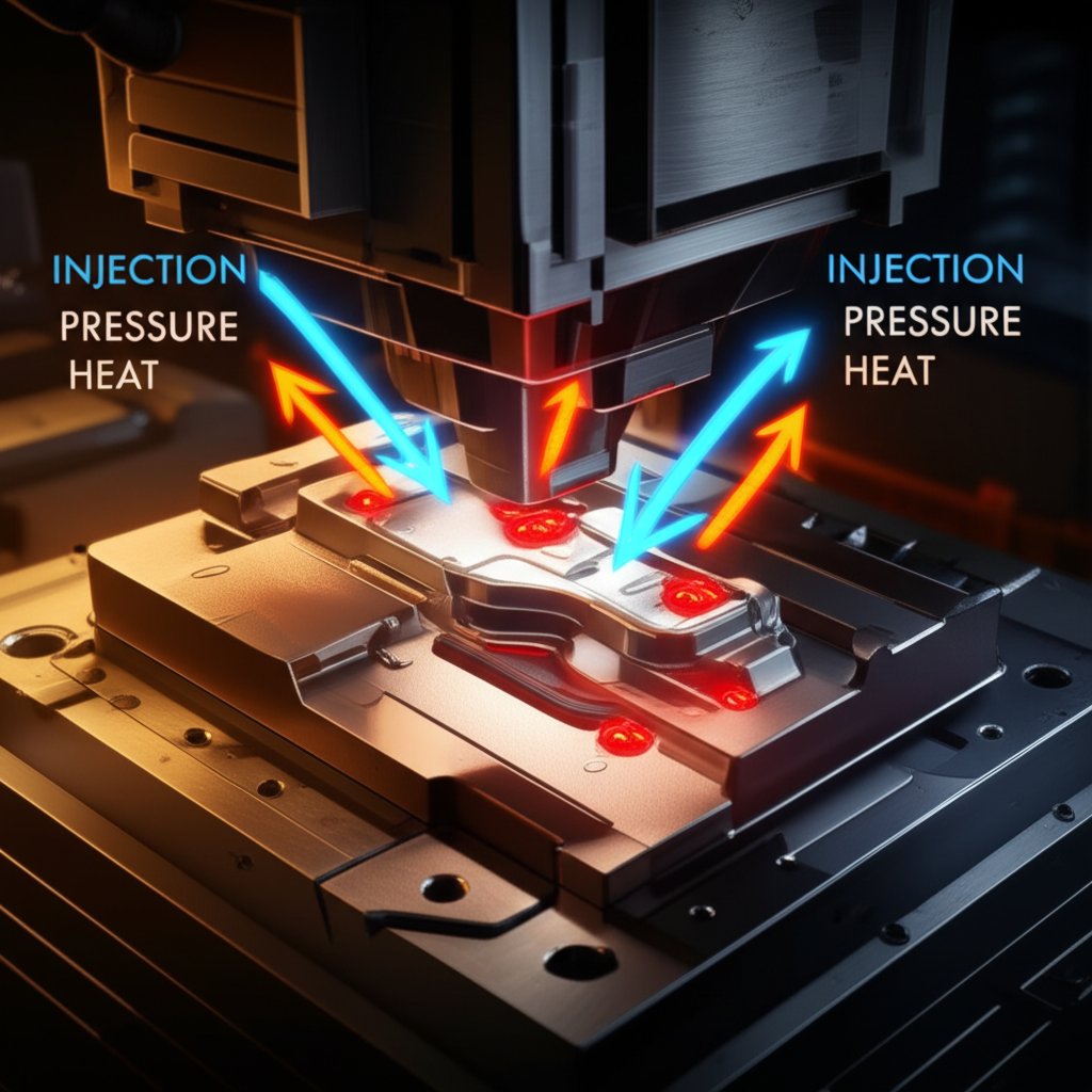
พารามิเตอร์ของกระบวนการมักเป็นประเด็นแรกที่ควรตรวจสอบ เนื่องจากสามารถปรับได้โดยไม่จำเป็นต้องแก้ไขแม่พิมพ์ทางกายภาพ ปัจจัยต่างๆ เช่น ความดันฉีดที่สูงเกินไป อาจทำให้วัสดุหลอมเหลวรัดแน่นกับผนังแม่พิมพ์มากเกินไป ส่งผลให้แรงยึดติดเพิ่มขึ้น และทำให้ต้องใช้แรงมากขึ้นในการดันชิ้นงานออก ในทำนองเดียวกัน อุณหภูมิแม่พิมพ์ที่สูงเกินไปหรือระยะเวลาการระบายความร้อนไม่เพียงพอ อาจทำให้ชิ้นงานยังนิ่มและเปลี่ยนรูปร่างได้ง่ายอยู่ในขณะที่หมุดดันถูกกระตุ้น ทำให้ชิ้นงานบุ๋มหรือเป็นรอยได้ ความเร็วการดันที่ไม่เหมาะสม—ไม่ว่าจะเร็วหรือช้าเกินไป—ก็อาจก่อให้เกิดแรงกระแทกหรือรอยลากบนชิ้นส่วนได้เช่นกัน
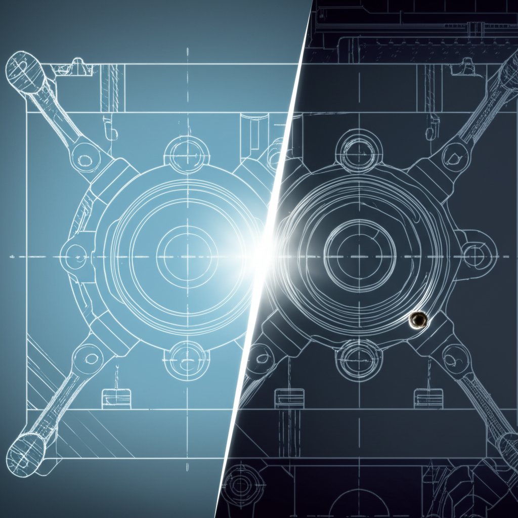
ในทางกลับกัน ปัญหาเครื่องหมายจากหมุดดันชิ้นงานจำนวนมากเกิดขึ้นจากกระบวนการออกแบบและการสร้างแม่พิมพ์ โดยเฉพาะมุมร่าง (draft angle) ที่ไม่เพียงพอ ซึ่งเป็นมุมเอียงเล็กน้อยบนพื้นผิวแนวตั้งของแม่พิมพ์ เนื่องจากมุมที่ไม่เหมาะสมจะเพิ่มแรงเสียดทานและความต้านทานอย่างมากในระหว่างการถอดชิ้นงานออก นอกจากนี้ การออกแบบระบบดันชิ้นงานเองก็มีความสำคัญไม่แพ้กัน การใช้หมุดดันจำนวนน้อยเกินไป หมุดที่มีขนาดเส้นผ่านศูนย์กลางเล็กเกินไป หรือการวางหมุดในตำแหน่งที่โครงสร้างอ่อนแอ จะทำให้แรงดันรวมอยู่ที่จุดใดจุดหนึ่ง ส่งผลให้เกิดการเปลี่ยนรูปเฉพาะที่ ทางที่ดีควรติดตั้งหมุดดันในตำแหน่งที่มีความแข็งแรงและไม่ใช่บริเวณที่มองเห็นได้ เช่น แผ่นเสริมแรง (ribs) หรือหัวนูน (bosses) เพื่อกระจายแรงให้สม่ำเสมอ
เพื่อช่วยในการวินิจฉัยปัญหา โปรดพิจารณาการแยกแยะสาเหตุทั่วไปต่อไปนี้:
| หมวดหมู่ | สาเหตุเฉพาะ |
|---|---|
| ข้อบกพร่องในการออกแบบแม่พิมพ์ |
|
| ปัญหาพารามิเตอร์กระบวนการ |
|
กลยุทธ์การป้องกันและลดปัญหาในระหว่างการออกแบบและการผลิต
วิธีที่มีประสิทธิภาพที่สุดในการจัดการกับรอยจากเข็มดันชิ้นงาน คือ การป้องกันไม่ให้ปัญหาเหล่านี้เกิดขึ้นตั้งแต่แรก เริ่มต้นด้วยแนวทางเชิงรุกตั้งแต่ขั้นตอนการออกแบบชิ้นส่วนและแม่พิมพ์ และดำเนินต่อไปจนถึงการปรับแต่งกระบวนการผลิตในสายการผลิต โดยการแก้ไขปัญหาที่อาจเกิดขึ้นตั้งแต่เนิ่นๆ ผู้ผลิตจะสามารถประหยัดเวลาและต้นทุนได้อย่างมาก ซึ่งมิเช่นนั้นอาจต้องเสียไปกับการซ่อมแซมหรือทิ้งชิ้นงานหลังการผลิต
ในขั้นตอนการออกแบบ วิศวกรควรเน้นการสร้างชิ้นส่วนที่เหมาะสมต่อการผลิตอย่างมีประสิทธิภาพ ซึ่งรวมถึงการกำหนดมุมร่อง (โดยทั่วไป 1-3 องศา) อย่างเพียงพอ เพื่อให้ถอดชิ้นงานออกจากแม่พิมพ์ได้ง่าย ตามรายละเอียดที่ระบุไว้ CEX Casting . การจัดวางและขนาดของสลักดันออกมีความสำคัญต่อการออกแบบอย่างยิ่ง เป้าหมายคือการกระจายแรงดันในการดันชิ้นงานออกให้ครอบคลุมพื้นที่ที่ใหญ่ที่สุดเท่าที่จะเป็นไปได้ในส่วนที่แข็งแรงที่สุดและไม่ใช่ส่วนตกแต่งของชิ้นงาน การใช้สลักมากขึ้นหรือสลักที่มีเส้นผ่านศูนย์กลางใหญ่ขึ้นสามารถลดแรงดันที่จุดใดจุดหนึ่งได้อย่างมีประสิทธิภาพ นอกจากนี้ ระบบระบายความร้อนที่ออกแบบมาอย่างดีจะช่วยให้ชิ้นงานแข็งตัวอย่างสม่ำเสมอ ทำให้มีความแข็งแรงพอที่จะทนต่อการดันออกโดยไม่เกิดความเสียหาย
สำหรับชิ้นส่วนที่มีความซับซ้อน โดยเฉพาะในภาคอุตสาหกรรมที่ต้องการคุณภาพสูง เช่น อุตสาหกรรมยานยนต์ การร่วมมือกับผู้ผลิตที่มีความเชี่ยวชาญลึกด้านแม่พิมพ์ถือเป็นสิ่งจำเป็น ตัวอย่างเช่น บริษัทที่ให้บริการฉีดขึ้นรูปแบบไดคัสติ้งแบบแม่นยำ มักมีการควบคุมคุณภาพอย่างเข้มงวด และมีความสามารถในการออกแบบได้เองภายในองค์กร ซึ่งสามารถลดปัญหาต่าง ๆ เหล่านี้ได้ตั้งแต่เริ่มต้น การทำงานร่วมกับผู้จัดจำหน่ายที่เชี่ยวชาญกระบวนการไดคัสติ้งขั้นสูงและมีการรับรองมาตรฐาน IATF16949 จะช่วยให้มั่นใจได้ว่าหลักการออกแบบเพื่อการผลิต (DFM) จะถูกนำไปใช้ เพื่อป้องกันข้อบกพร่อง เช่น รอยหมุดดันออก ก่อนที่การผลิตจะเริ่มขึ้น
เมื่อเริ่มการผลิตแล้ว ผู้ปฏิบัติงานสามารถดำเนินการตรวจสอบอย่างเป็นระบบเพื่อลดความเสี่ยง:
- ปรับแต่งพารามิเตอร์การฉีดให้เหมาะสม: เริ่มต้นด้วยการลดแรงดันฉีด แรงดันคงที่ และระยะเวลาค้างไว้ให้อยู่ในระดับต่ำที่สุดเท่าที่ยังสามารถผลิตชิ้นส่วนให้สมบูรณ์ได้ วิธีนี้จะช่วยลดแรงที่ยึดชิ้นส่วนไว้ในแม่พิมพ์
- ควบคุมสภาพอุณหภูมิ: ตรวจสอบให้มั่นใจว่าอุณหภูมิแม่พิมพ์อยู่ในช่วงที่แนะนำสำหรับวัสดุที่ใช้ ควรเพิ่มเวลาในการทำความเย็นเพื่อให้ชิ้นงานได้รับความแข็งแรงเพียงพอ ก่อนที่จะดันออก
- ปรับตั้งค่าการดันออก: ลดความเร็วการดันออกเพื่อป้องกันแรงกระแทกทันที ตรวจสอบให้มั่นใจว่าหมุดดันอยู่ในแนวที่ถูกต้องและเคลื่อนที่ได้อย่างลื่นไหล
- ใช้สารหล่อลื่นแม่พิมพ์: ใช้สารหล่อลื่นแม่พิมพ์ที่เหมาะสม โดยพ่นเป็นชั้นบางๆ อย่างสม่ำเสมอ การพ่นมากเกินไปอาจก่อให้เกิดข้อบกพร่องอื่นๆ จึงจำเป็นต้องใช้เทคนิคที่ถูกต้อง
- บำรุงรักษาแม่พิมพ์: ตรวจสอบและทำความสะอาดโพรงแม่พิมพ์และหมุดดันอย่างสม่ำเสมอ การขัดเงาผิวแม่พิมพ์สามารถช่วยลดแรงเสียดทานและการติดได้อย่างมาก
แนวทางแก้ไขหลังการผลิต: วิธีการลบเครื่องหมายจากหมุดดัน
แม้ว่าการป้องกันล่วงหน้าจะเป็นกลยุทธ์ที่ดีที่สุดเสมอ แต่ก็มีบางกรณีที่ร่องรอยของหมุดดันอาจยังคงปรากฏบนชิ้นส่วนที่ผลิตเสร็จแล้ว หรือเมื่อทำงานกับแม่พิมพ์รุ่นเก่าที่ไม่สามารถปรับเปลี่ยนการออกแบบได้ ในกรณีเหล่านี้สามารถใช้เทคนิคหลังการผลิตเพื่อลบหรือปกปิดร่องรอยดังกล่าว โดยเฉพาะอย่างยิ่งสำหรับการใช้งานที่ต้องการความสวยงาม ซึ่งลักษณะผิวของชิ้นงานมีความสำคัญมาก วิธีการเหล่านี้จะเพิ่มระยะเวลาและต้นทุนแรงงานให้กับกระบวนการผลิต จึงมักใช้เฉพาะในสถานการณ์ที่การทิ้งชิ้นส่วนนั้นไม่ใช่ทางเลือกที่เหมาะสม
วิธีที่ใช้กันทั่วไปที่สุดสำหรับการแก้ปัญหารอยบุ๋มคือการอุดเติมเต็ม กระบวนการนี้เกี่ยวข้องกับการนำวัสดุอุดเติม เช่น ปูนยาแนวพิเศษหรืออีพ็อกซี่ มาใส่ในร่องลึกที่เกิดจากหมุดดันชิ้นงาน ตัวเลือกวัสดุอุดเติมจะขึ้นอยู่กับวัสดุพื้นฐานของชิ้นส่วนที่หล่อขึ้นรูปด้วยแม่พิมพ์โลหะ และสภาพผิวที่ต้องการ หลังจากที่วัสดุอุดเติมถูกนำไปใช้และแข็งตัวเต็มที่แล้ว วัสดุส่วนเกินจะถูกลบออกอย่างระมัดระวังโดยการขัดให้เรียบเสมอกับพื้นผิวโดยรอบ ซึ่งมักจะตามด้วยการขัดเงาเพื่อให้บริเวณที่ซ่อมแซมกลมกลืนไปกับส่วนอื่นๆ ของชิ้นส่วนอย่างไร้รอยต่อ เทคนิคนี้มีประสิทธิภาพแต่ต้องอาศัยทักษะในการซ่อมให้มองไม่เห็น โดยเฉพาะกับชิ้นส่วนที่จะต้องนำไปพ่นสีหรือชุบ
สำหรับข้อบกพร่องเล็กน้อย เช่น นูนเล็กน้อยหรือสีผิวไม่สม่ำเสมอ วิธีการตกแต่งทางกลอาจเพียงพอได้ การขัดหรือขัดมันสามารถใช้เพื่อเรียบพื้นผิวที่นูนขึ้น ในขณะที่เทคนิคต่างๆ เช่น การพ่นทรายสามารถสร้างพื้นผิวที่สม่ำเสมอ ซึ่งช่วยปกปิดข้อบกพร่องเล็กน้อยได้อย่างมีประสิทธิภาพ อย่างไรก็ตาม ควรพิจารณาข้อกำหนดของชิ้นส่วนอย่างรอบคอบ เนื่องจากวิธีการกัดกร่อนเหล่านี้จะทำให้วัสดุสูญเสียไป และอาจส่งผลต่อค่าความคลาดเคลื่อนของขนาด สำหรับการซ่อมแซมใดๆ หลังการผลิต การชั่งน้ำหนักต้นทุนที่เพิ่มขึ้นกับมูลค่าของการรักษาชิ้นส่วนไว้จึงเป็นสิ่งสำคัญยิ่ง
หากคุณจำเป็นต้องดำเนินการซ่อมแซม ให้ทำตามขั้นตอนทั่วไปต่อไปนี้:
- ประเมินข้อบกพร่อง: พิจารณาว่ารอยนั้นเป็นรอยบุ๋ม นูน หรือเพียงแค่รอยตำหนิบนผิว เนื่องจากสิ่งนี้จะเป็นตัวกำหนดวิธีการซ่อมแซมที่เหมาะสม
- เตรียมพื้นผิว: ทำความสะอาดบริเวณรอบรอยอย่างทั่วถึง เพื่อขจัดคราบน้ำมัน ไขมัน หรือสารหล่อลื่นต่างๆ ที่อาจติดอยู่ เพื่อให้สารยัดหรือสารเคลือบยึดติดได้อย่างมีประสิทธิภาพ
- ใช้สารยัด (สำหรับรอยบุ๋ม): หากต้องการเติมบริเวณที่บุ๋ม ให้ทาน้ำยาหรืออีพ็อกซี่ที่เหมาะสมลงบนรอยนั้น โดยเติมให้สูงกว่าเล็กน้อยเพื่อชดเชยการหดตัวและขั้นตอนการขัดทราย ปล่อยให้วัสดุเซ็ตตัวเต็มที่ตามคำแนะนำของผู้ผลิต
- ขัดและขัดเงา: ขัดบริเวณวัสดุที่เติมแล้วหรือรอยนูนอย่างระมัดระวัง จนพื้นผิวเรียบเสมอกันอย่างสมบูรณ์ เริ่มจากการใช้กระดาษทรายเบอร์หยาบ แล้วค่อยเปลี่ยนเป็นเบอร์ละเอียดขึ้นเรื่อยๆ เพื่อให้ได้พื้นผิวเรียบเนียน ขัดเงาบริเวณนั้นให้เข้ากับพื้นผิวเดิม
- ขั้นตอนการตกแต่งสุดท้าย: หากชิ้นส่วนนั้นจะถูกทาสีหรือเคลือบ ควรพ่นรองพื้นบริเวณที่ซ่อมแซมก่อน เพื่อให้แน่ใจว่าลักษณะสุดท้ายจะสม่ำเสมอ
คำถามที่พบบ่อย
1. สาเหตุของรอยอีเจ็คเตอร์เกิดจากอะไร?
รอยอีเจ็คเตอร์เกิดขึ้นหลักจากการที่แรงกระทำต่อชิ้นส่วนหล่อขึ้นรูปขณะถอดออกจากแม่พิมพ์ ปัจจัยสำคัญได้แก่ ความดันฉีดสูงเกินไป อุณหภูมิแม่พิมพ์สูงเกินไป เวลาในการเย็นตัวไม่เพียงพอ หรือการออกแบบแม่พิมพ์ที่ไม่เหมาะสม เช่น มุมร่างน้อยเกินไป หรือระบบอีเจ็คเตอร์ที่กระจายแรงมากเกินไปในบริเวณเล็กๆ ของชิ้นงาน
2. ร่องรอยจากหมุดดันออกมีจุดประสงค์อะไร
ร่องรอยจากหมุดดันออกเองนั้นไม่มีจุดประสงค์ใดๆ โดยตัวร่องรอยดังกล่าวเป็นผลพลอยได้ที่ไม่พึงประสงค์จากขั้นตอนการผลิตที่จำเป็น หมุดดันที่ก่อให้เกิดร่องรอยเหล่านี้มีความจำเป็นอย่างยิ่งในการดันชิ้นส่วนที่ผลิตเสร็จแล้วออกจากช่องแม่พิมพ์ เป้าหมายในการผลิตคือการควบคุมกระบวนการดันออกเพื่อให้ร่องรอยเหล่านี้มีขนาดเล็กที่สุด หรืออยู่ในพื้นผิวที่มองไม่เห็นและไม่ใช่พื้นที่สำคัญของชิ้นส่วน
3. จะอุดร่องรอยหมุดดันออกอย่างไร
ในการอุดร่องรอยหมุดดันที่เป็นหลุมเว้า ให้ใช้วัสดุอุดเติม เช่น อีพอกซี หรือปูนกาวพิเศษ ทาลงไปในบริเวณที่เป็นหลุม หลังจากวัสดุอุดเติมแข็งตัวแล้ว ให้ขัดให้เรียบเสมอกับพื้นผิวของชิ้นส่วน จากนั้นจึงขัดมันหรือทำพื้นผิวให้ตรงกับบริเวณโดยรอบ เพื่อให้การซ่อมดูแทบไม่เห็น
4. สาเหตุที่ทำให้เกิดรูเข็มในงานหล่อคืออะไร
รูเข็มเป็นข้อบกพร่องจากการหล่อที่ต่างออกไปจากรอยหมุดดันออก รูเข็มคือรูพรุนหรือโพรงเล็ก ๆ ที่เกิดขึ้นบนผิวหรือใต้ผิวของชิ้นงานหล่อ ซึ่งมักเกิดจากแก๊สที่ถูกกักไว้ เช่น ไฮโดรเจนจากความชื้นในโลหะเหลว หรืออากาศที่ถูกกักไว้เนื่องจากระบบระบายอากาศไม่ดีพอในแม่พิมพ์ระหว่างกระบวนการแข็งตัว