 ผลิตจำนวนน้อย แต่มีมาตรฐานสูง บริการสร้างต้นแบบอย่างรวดเร็วของเรามาพร้อมกับการตรวจสอบที่เร็วขึ้นและง่ายขึ้น —

การผลิตชิ้นส่วนโลหะแผ่นแบบกำหนดเองอย่างแม่นยำ: จากวัตถุดิบไปจนถึงชิ้นส่วนสำเร็จรูป
ความหมายที่แท้จริงของบริการขึ้นรูปโลหะแผ่นแบบกำหนดเองด้วยความแม่นยำสูง
เมื่อคุณได้ยินคำว่า " โลหะแผ่นความแม่นยำแบบกำหนดเอง คุณนึกถึงอะไรเป็นอันดับแรก? สำหรับวิศวกรและผู้จัดการโครงการจำนวนมาก แนวคิดนี้ฟังดูมีลักษณะทางเทคนิค — และก็เป็นเช่นนั้นจริง ๆ แต่การเข้าใจความหมายที่แท้จริงของมันสามารถเปลี่ยนแปลงวิธีที่คุณดำเนินโครงการผลิตครั้งต่อไปของคุณได้อย่างสิ้นเชิง
โดยพื้นฐานแล้ว การขึ้นรูปโลหะแผ่นด้วยความแม่นยำสูง คือกระบวนการตัด ดัด และขึ้นรูปแผ่นโลหะแบนให้กลายเป็นชิ้นส่วนสำเร็จรูปที่มีความแม่นยำสูงมาก ส่วนคำว่า "กำหนดเอง" หมายความว่า ชิ้นส่วนเหล่านี้ถูกออกแบบและผลิตขึ้นเฉพาะตามข้อกำหนดด้านการออกแบบของคุณ โดยไม่ได้นำมาจากรายการสินค้ามาตรฐานที่มีขนาดตายตัว อย่างไรก็ตาม สิ่งที่ทำให้กระบวนการนี้แตกต่างอย่างแท้จริงคือระดับของการควบคุมมิติ (dimensional control) ซึ่งเป็นตัวแยกระหว่างชิ้นส่วนที่ใช้งานได้จริงกับชิ้นส่วนที่ประกอบไม่สำเร็จ
นิยามของคำว่า "ความแม่นยำ" ในบริบทของการขึ้นรูปโลหะแผ่น
แล้วคำว่า "ความแม่นยำ" นั้นหมายความว่าอย่างไรในเชิงตัวเลขที่วัดได้? ทั้งหมดนี้ขึ้นอยู่กับค่าความคลาดเคลื่อนที่ยอมรับได้ (tolerances) — คือขอบเขตของความแปรผันที่ยอมรับได้ในมิติของชิ้นส่วน ซึ่งจะทำให้ชิ้นส่วนนั้นสามารถติดตั้งได้พอดี ทำงานได้ตามหน้าที่ และให้สมรรถนะที่เหมาะสมในแอปพลิเคชันที่ออกแบบไว้
การขึ้นรูปแผ่นโลหะด้วยความแม่นยำสูงสามารถบรรลุค่าความคลาดเคลื่อนที่แน่นหนามากถึง ±0.001 นิ้ว โดยใช้เทคโนโลยี CNC ขั้นสูง เครื่องมือวัดที่ทันสมัยที่สุด และขั้นตอนการควบคุมคุณภาพอย่างพิถีพิถัน ความแม่นยำระดับนี้รับประกันว่าชิ้นส่วนจะสามารถติดตั้งเข้ากับระบบที่ใหญ่ขึ้นได้อย่างลงตัว ในขณะเดียวกันก็ให้ประสิทธิภาพที่เชื่อถือได้และทำซ้ำได้อย่างสม่ำเสมอ
จินตนาการถึงค่าความคลาดเคลื่อนเหมือนเป้าหมายในการยิงธนู การขึ้นรูปแบบมาตรฐานอาจยิงได้ใกล้เคียงกับจุดศูนย์กลางภายในระยะไม่กี่นิ้ว แต่การขึ้นรูปแบบความแม่นยำสูงนั้นสามารถยิงได้ตรงจุดศูนย์กลางอย่างสม่ำเสมอภายในเศษส่วนของมิลลิเมตรเท่านั้น สำหรับอุตสาหกรรมต่าง ๆ เช่น ยานยนต์ อุปกรณ์ทางการแพทย์ และอุปกรณ์อิเล็กทรอนิกส์ ความแตกต่างเพียงเล็กนี้คือตัวกำหนดว่าชิ้นส่วนประกอบของคุณจะทำงานได้อย่างไร้ที่ติ หรือล้มเหลวในการตรวจสอบ
ค่าความคลาดเคลื่อนส่งผลต่อทุกสิ่ง ตั้งแต่คุณภาพของขอบชิ้นงาน ตำแหน่งของรู ไปจนถึงมุมของการดัด ค่าความคลาดเคลื่อนทั่วไปสำหรับแผ่นโลหะอาจอยู่ที่บวกหรือลบสิบในหนึ่งหมื่นของนิ้ว ตลอดแนวการดัด — ซึ่งหลวมกว่าค่าความคลาดเคลื่อนในการกลึงอย่างมาก แต่ก็ยังคงต้องอาศัยการควบคุมกระบวนการอย่างรอบคอบ
สิ่งที่ทำให้การขึ้นรูปตามสั่งแตกต่างจากการผลิตแบบมาตรฐาน
คุณอาจสงสัยว่า: ทำไมไม่ใช้ชิ้นส่วนที่มีจำหน่ายทั่วไปแทนล่ะ? คำตอบอยู่ที่ข้อกำหนดเฉพาะสำหรับการใช้งานจริง ซึ่งชิ้นส่วนมาตรฐานไม่สามารถตอบสนองได้
การผลิตชิ้นส่วนโลหะตามแบบเฉพาะ (Custom metal fabrication) ผสานเทคนิคความแม่นยำเข้ากับความต้องการด้านการออกแบบที่ไม่เหมือนใคร เพื่อจัดหาโซลูชันที่ออกแบบมาโดยเฉพาะ ต่างจากงานผลิตแบบมาตรฐาน ซึ่งใช้วิธีพื้นฐาน เช่น การตัด การดัด และการเชื่อม เพื่อผลิตชิ้นส่วนที่เรียบง่ายและมีค่าความคลาดเคลื่อน (tolerance) ค่อนข้างหลวม ขณะที่งานความแม่นยำสูงจะใช้วิธีขั้นสูง เช่น การกลึงด้วยเครื่อง CNC การตัดด้วยเลเซอร์ และระบบขึ้นรูปอัตโนมัติ
พิจารณาความแตกต่างสำคัญเหล่านี้:
- ความยืดหยุ่นในการออกแบบ: ชิ้นส่วนของคุณสอดคล้องกับข้อกำหนดเฉพาะของคุณอย่างแม่นยำ ไม่ใช่เพียงการประมาณค่าจากแคตตาล็อก
- การเพิ่มประสิทธิภาพวัสดุ: เลือกโลหะผสม ความหนา และพื้นผิวผ่านการตกแต่งที่เหมาะสมกับการใช้งานเฉพาะของคุณ
- ความพร้อมในการรวมเข้ากับระบบทั้งหมด: ชิ้นส่วนความแม่นยำสูงสามารถติดตั้งได้อย่างถูกต้องในครั้งแรก จึงหลีกเลี่ยงการปรับเปลี่ยนเพิ่มเติมในสถานที่ซึ่งมีค่าใช้จ่ายสูง
ระดับของการปรับแต่งนี้มีความสำคัญมากที่สุดในโครงการขึ้นรูปโลหะ ซึ่งชิ้นส่วนต้องเชื่อมต่อกับชุดประกอบอื่นๆ ที่มีความแม่นยำสูง เมื่อทุกเศษส่วนของมิลลิเมตรมีผลต่อคุณภาพ การขึ้นรูปตามแบบเฉพาะจึงกลายเป็นสิ่งจำเป็น ไม่ใช่เพียงทางเลือก
บทบาทของความคลาดเคลื่อนที่แคบในกระบวนการผลิตสมัยใหม่
เหตุใดความคลาดเคลื่อนจึงมีความสำคัญอย่างยิ่งในสภาพแวดล้อมการผลิตปัจจุบัน? เพราะความคลาดเคลื่อนส่งผลกระทบโดยตรงต่อผลลัพธ์ที่สำคัญสามประการ ได้แก่ ความพอดีของชิ้นส่วน ประสิทธิภาพในการประกอบ และความน่าเชื่อถือของผลิตภัณฑ์ในระยะยาว
ชิ้นส่วนที่มีความแม่นยำสูงช่วยกำจัดความไม่สม่ำเสมอและจุดที่เกิดแรงเครียดสะสม ซึ่งเป็นสาเหตุให้เกิดการสึกหรอหรือเสียหายก่อนวัยอันควร เมื่อชิ้นส่วนสามารถประกอบเข้าด้วยกันได้อย่างลงตัวโดยไม่ต้องใช้แรงกดหรือแทรกแผ่นรอง (shim) จะช่วยลดเวลาในการประกอบและต้นทุนแรงงานลง ขณะที่เมื่อขนาดของชิ้นส่วนคงที่ตลอดทุกครั้งของการผลิต ระบบควบคุมคุณภาพของคุณจะสามารถคาดการณ์ผลลัพธ์ได้ล่วงหน้า แทนที่จะต้องดำเนินการแบบตอบสนองหลังเกิดปัญหา
อุตสาหกรรมต่างๆ เช่น อุปกรณ์ระบบส่งจ่ายไฟฟ้า ระบบยานยนต์ และอุปกรณ์อิเล็กทรอนิกส์ กำหนดมาตรฐานที่เข้มงวดอย่างยิ่ง เนื่องจากข้อผิดพลาดอาจนำไปสู่การทำงานผิดปกติของอุปกรณ์ ข้อบกพร่องของผลิตภัณฑ์ หรือความเสี่ยงด้านความปลอดภัย การตอบสนองต่อข้อกำหนดเหล่านี้เริ่มต้นจากการเข้าใจว่า ขอบเขตความคลาดเคลื่อน (tolerances) ที่แอปพลิเคชันของคุณต้องการจริงๆ นั้นคืออะไร—ไม่ใช่การเลือกใช้ข้อกำหนดที่เข้มงวดเกินความจำเป็นซึ่งจะเพิ่มต้นทุนโดยไม่สร้างมูลค่าเพิ่ม
ตลอดคู่มือนี้ คุณจะได้เรียนรู้วิธีระบุขอบเขตความคลาดเคลื่อนอย่างถูกต้อง เลือกวัสดุที่เหมาะสม และออกแบบชิ้นส่วนให้บรรลุสมดุลระหว่างความแม่นยำกับประสิทธิภาพด้านต้นทุนอย่างเหมาะสมที่สุด โปรดพิจารณาคู่มือนี้เป็นแหล่งข้อมูลอ้างอิงฉบับสมบูรณ์สำหรับการนำทางในโลกของชิ้นส่วนความแม่นยำ—ตั้งแต่แนวคิดเบื้องต้นจนถึงการผลิตเสร็จสมบูรณ์
คู่มือการเลือกวัสดุสำหรับโครงการแผ่นโลหะความแม่นยำ
เมื่อคุณเข้าใจแล้วว่าการขึ้นรูปแบบแม่นยำ (precision fabrication) หมายถึงอะไรจริง ๆ คำถามสำคัญข้อต่อไปก็คือ: คุณควรเลือกวัสดุชนิดใดสำหรับโครงการของคุณ? การเลือกวัสดุไม่ได้ขึ้นอยู่เพียงแค่ต้นทุนหรือความพร้อมใช้งานเท่านั้น — แต่ยังส่งผลโดยตรงต่อค่าความคลาดเคลื่อน (tolerances) ที่คุณสามารถบรรลุได้ วิธีการขึ้นรูป (forming methods) ที่คุณสามารถใช้ได้ และในที่สุดก็คือประสิทธิภาพการทำงานของชิ้นส่วนสำเร็จรูปของคุณ
โลหะแต่ละชนิดมีพฤติกรรมที่แตกต่างกันภายใต้แรงเครียดจากการตัด การดัด และการขึ้นรูป บางชนิดมีการคืนตัว (spring back) อย่างมากหลังการดัด ทำให้ยากต่อการควบคุมความคลาดเคลื่อนเชิงมุมอย่างแม่นยำ ในขณะที่บางชนิดเกิดการแข็งตัวจากการขึ้นรูป (work-harden) อย่างรวดเร็ว ซึ่งจำกัดจำนวนครั้งของการดำเนินการขึ้นรูปที่สามารถทำได้ การเข้าใจลักษณะเหล่านี้จะช่วยให้คุณตัดสินใจอย่างมีข้อมูล โดยคำนึงถึงสมดุลระหว่างข้อกำหนดด้านความแม่นยำกับความสามารถในการผลิตจริง
เกรดเหล็กและลักษณะเฉพาะด้านความแม่นยำ
เหล็กยังคงเป็น วัสดุหลักในการขึ้นรูปแผ่นโลหะแบบแม่นยำ ให้สมดุลที่ยอดเยี่ยมระหว่างความแข็งแรง ความสามารถในการขึ้นรูป และความคุ้มค่า แต่ไม่ใช่ทุกเกรดของเหล็กจะให้ผลการดำเนินงานเท่าเทียมกันเมื่อความแม่นยำมีความสำคัญ
เหล็กอ่อน (เหล็กคาร์บอนต่ำ) เช่น DC01 มีปริมาณคาร์บอนต่ำมาก ทำให้มีความเหนียวและสามารถขึ้นรูปได้ง่าย ตามข้อกำหนดวัสดุของ Xometry เหล็กชนิดนี้สามารถเชื่อม ประสานโลหะ (brazing) และบัดกรีได้อย่างง่ายดาย พฤติกรรมที่คาดการณ์ได้ในระหว่างการขึ้นรูปทำให้เหมาะสำหรับชิ้นส่วนที่ต้องการมุมการดัดที่สม่ำเสมอและค่าความคลาดเคลื่อนเชิงมิติที่แคบ
เหล็กโครงสร้าง เช่น S235JR มีความพลาสติก ความเหนียว และความสามารถในการเชื่อมที่ดี พร้อมทั้งมีค่าความต้านทานแรงดึงต่ำกว่า จึงสามารถขึ้นรูปเป็นผลิตภัณฑ์หลากหลายชนิดได้ วัสดุเหล่านี้ใช้งานได้ดีสำหรับโครงยึดแบบแม่นยำ ฝาครอบ และชิ้นส่วนโครงสร้างที่ต้องการความแข็งแรงระดับปานกลางควบคู่ไปกับความยืดหยุ่นในการขึ้นรูป
สำหรับการใช้งานที่ต้องการความแข็งแรงดึงสูง—มากกว่า 630 เมกะพาสคัล—เหล็กกล้าคาร์บอนปานกลาง เช่น ST52 จะให้ความทนทานที่โดดเด่นอย่างยิ่ง อย่างไรก็ตาม ความแข็งที่เพิ่มขึ้นของวัสดุชนิดนี้ส่งผลให้เกิดปรากฏการณ์สปริงแบ็ก (springback) มากขึ้นระหว่างการดัด จึงจำเป็นต้องมีการปรับชดเชยในการตั้งค่าแม่พิมพ์เพื่อให้ได้มิติเป้าหมายที่ต้องการ
โลหะผสมอลูมิเนียมสำหรับชิ้นส่วนความแม่นยำที่มีน้ำหนักเบา
เมื่อการลดน้ำหนักมีความสำคัญ แผ่นโลหะอลูมิเนียมถือเป็นทางเลือกที่น่าสนใจแทนเหล็ก—โดยทั่วไปมีน้ำหนักเพียงหนึ่งในสามของเหล็ก และมีความต้านทานการกัดกร่อนที่ยอดเยี่ยม แต่ความแข็งแรงดึงที่ต่ำกว่าของอลูมิเนียมและลักษณะการเกิดสปริงแบ็กที่แตกต่างกัน จำเป็นต้องพิจารณาอย่างรอบคอบ
โลหะผสมซีรีส์ 5000 (เช่น 5052 และ 5083) มีแมกนีเซียมเป็นธาตุหลักที่ใช้ในการผสม ซึ่งให้ความต้านทานการกัดกร่อนที่ยอดเยี่ยมและสามารถขึ้นรูปได้ดี โลหะผสม 5083 ให้ความแข็งแรงสูงสุดในบรรดาแผ่นอลูมิเนียมที่ไม่สามารถผ่านกระบวนการอบความร้อนเพื่อเพิ่มความแข็งแรงได้ อย่างไรก็ตาม ไม่แนะนำให้นำไปใช้งานที่อุณหภูมิสูงเกิน 65 องศาเซลเซียส
โลหะผสมซีรีส์ 6000 มีคุณสมบัติที่สามารถผ่านกระบวนการอบความร้อนเพื่อเพิ่มความแข็งแรงได้ โดยมีระดับความแข็งแรงที่แตกต่างกัน:
- อลูมิเนียม 6060: ความแข็งแรงต่ำถึงปานกลาง เหมาะมากสำหรับการขึ้นรูปเย็น—เหมาะอย่างยิ่งเมื่อต้องการโค้งที่ซับซ้อน
- อลูมิเนียม 6061: มีคุณสมบัติเชิงกลที่ดีพร้อมความสามารถในการเชื่อมที่ยอดเยี่ยม มักใช้กระบวนการอัดรีดสำหรับงานที่ต้องการความแม่นยำสูง
- อลูมิเนียมเกรด 6082: มีความแข็งแรงระดับกลางพร้อมการนำความร้อนที่ดีมาก โดยทั่วไปจะขึ้นรูปด้วยกระบวนการรีดและอัดรีด
เพื่อให้ได้อัตราส่วนของความแข็งแรงต่อน้ำหนักสูงสุด โลหะผสมซีรีส์ 7000 เช่น 7020 ซึ่งรวมสังกะสีและแมกนีเซียมเข้าด้วยกัน เพื่อให้ได้ความแข็งแรงสูงเป็นพิเศษ ขณะเดียวกันก็ยังคงเป็นหนึ่งในโลหะผสมเชิงพาณิชย์ที่เบากว่าโลหะผสมอื่นๆ วัสดุเหล่านี้โดดเด่นในงานที่ต้องการความทนทานสูงและความต้านทานต่อการเหนื่อยล้า
โลหะเฉพาะทาง รวมถึงสแตนเลสสตีลและทองแดง
การใช้งานบางประเภทต้องการคุณสมบัติเฉพาะของวัสดุที่เหล็กหรืออลูมิเนียมมาตรฐานไม่สามารถให้ได้ นี่คือจุดที่โลหะเฉพาะทางเข้ามามีบทบาท
เหล็กกล้าไม่สนิมแผ่น ให้ความต้านทานการกัดกร่อนที่เหนือกว่าด้วยปริมาณโครเมียมที่มีอยู่ ซึ่งมีสองเกรดที่ใช้กันอย่างแพร่หลายในการผลิตชิ้นส่วนความแม่นยำสูง:
- สเตนเลสเกรด 304: โลหะผสมโครเมียม-นิกเกิลแบบออสเทนิติกที่มีความต้านทานการกัดกร่อนได้ดีเยี่ยม สามารถขึ้นรูปและตัดแต่งได้ง่าย มักใช้กันอย่างแพร่หลายในอุตสาหกรรมอาหาร เครื่องดื่ม และอุตสาหกรรมทั่วไป
- สเตนเลส 316: เพิ่มโมลิบดีนัมเพื่อปรับปรุงความต้านทานต่อกรดคลอริกและกรดที่ไม่ใช่สารออกซิไดซ์ รวมทั้งเติมไนโตรเจนเพื่อเพิ่มความทนทาน — เป็นวัสดุที่นิยมใช้มากที่สุดในสภาพแวดล้อมทางทะเลและการแปรรูปสารเคมี
แผ่นสแตนเลสทั้งสองชนิดนี้มีค่าการนำความร้อนต่ำกว่าเหล็กคาร์บอน ซึ่งส่งผลต่อความเร็วในการตัดและการจัดการความร้อนระหว่างการประมวลผลด้วยเลเซอร์
เมื่อพิจารณาการเลือกระหว่างทองเหลืองกับบรอนซ์สำหรับการใช้งานของคุณ โปรดจำไว้ว่า ทองเหลือง (โลหะผสมทองแดง-สังกะสี) มีความสามารถในการขึ้นรูปได้ดีเยี่ยมและมีการนำไฟฟ้าสูง ในขณะที่บรอนซ์ (โลหะผสมทองแดง-ดีบุก) มีความต้านทานการสึกหรอได้ดีกว่า ส่วนการผสมแผ่นเหล็กกับทองแดง—ซึ่งบางครั้งเรียกว่าเหล็กเคลือบผิวด้วยทองแดง—จะให้คุณสมบัติด้านการนำไฟฟ้าเหมือนทองแดง พร้อมทั้งความแข็งแรงเชิงโครงสร้างจากเหล็ก
| วัสดุ | ช่วงความหนาทั่วไป | คะแนนความสามารถในการขึ้นรูป | ความต้านทานการกัดกร่อน | ราคาสัมพัทธ์ | การใช้งานที่เหมาะสม |
|---|---|---|---|---|---|
| เหล็กกล้าอ่อน (DC01) | 0.5mm - 3.0mm | ยอดเยี่ยม | ต่ำ (ต้องใช้ชั้นเคลือบ) | $ | ขาแขวน กล่องหุ้ม การผลิตทั่วไป |
| สแตนเลส 304 | 0.5 มม. - 6.0 มม. | ดี | ยอดเยี่ยม | $$$ | อุปกรณ์สำหรับอุตสาหกรรมอาหาร อุปกรณ์ทางการแพทย์ งานสถาปัตยกรรม |
| สแตนเลส 316 | 0.5 มม. - 6.0 มม. | ดี | ผู้นํา | $$$$ | การใช้งานในทะเล, การแปรรูปสารเคมี, อุตสาหกรรมยา |
| อลูมิเนียม 5052 | 0.5 มม. - 6.0 มม. | ยอดเยี่ยม | ดีมาก | $$ | ชิ้นส่วนสำหรับงานทะเล ถังเชื้อเพลิง ภาชนะความดัน |
| อลูมิเนียม 6061 | 0.5 มม. - 6.0 มม. | ดี | ดี | $$ | ชิ้นส่วนโครงสร้าง โครงถัก และชิ้นส่วนเครื่องจักร |
| ทองแดง | 0.3 มม. – 3.0 มม. | ยอดเยี่ยม | ดี | $$$$ | ชิ้นส่วนไฟฟ้า เครื่องแลกเปลี่ยนความร้อน และการป้องกันการรบกวนจากคลื่นแม่เหล็กไฟฟ้า (EMI shielding) |
| ทองเหลือง | 0.3 มม. – 3.0 มม. | ดีมาก | ดี | $$$ | ชิ้นส่วนตกแต่ง ขั้วต่อไฟฟ้า และอุปกรณ์ยึดติด |
การเลือกวัสดุมีผลต่อความแม่นยำที่สามารถบรรลุได้อย่างไร? โลหะทุกชนิดมีปรากฏการณ์การคืนตัว (springback) คือ แนวโน้มที่จะคืนตัวบางส่วนกลับสู่รูปร่างเดิมหลังจากการดัด วัสดุที่มีความแข็งแรงสูง เช่น เหล็กกล้าไร้สนิมและอลูมิเนียมซีรีส์ 7000 จะมีการคืนตัวมากกว่าเหล็กคาร์บอนต่ำหรือทองแดง จึงจำเป็นต้องมีการดัดเกินค่าเป้าหมาย (overbending compensation) เพื่อให้ได้มุมที่ต้องการ
นอกจากนี้ วัสดุที่มีความต้านแรงดึงสูงโดยทั่วไปจะให้ขอบตัดที่เรียบสะอาดกว่าในกระบวนการตัดด้วยเลเซอร์ แต่อาจต้องใช้อัตราการป้อนที่ช้าลง ขณะที่วัสดุที่นุ่มกว่า เช่น ทองแดงและอลูมิเนียม สามารถตัดได้เร็วกว่า แต่อาจเกิดเศษคม (burrs) ซึ่งจำเป็นต้องผ่านกระบวนการตกแต่งเพิ่มเติม
การเลือกวัสดุของคุณขึ้นอยู่กับการสมดุลระหว่างความต้องการเชิงกล ปัจจัยด้านสิ่งแวดล้อมที่วัสดุจะสัมผัส ความแม่นยำของค่าความคลาดเคลื่อนที่ยอมรับได้ และข้อจำกัดด้านงบประมาณ ด้วยพื้นฐานความเข้าใจในคุณสมบัติของวัสดุนี้ คุณจึงพร้อมที่จะศึกษากระบวนการผลิตที่เปลี่ยนแผ่นวัสดุดิบให้กลายเป็นชิ้นส่วนที่มีความแม่นยำสูง
กระบวนการผลิตหลักและศักยภาพด้านความแม่นยำของแต่ละกระบวนการ
คุณได้เลือกวัสดุแล้ว คำถามสำคัญต่อไปคือ: กระบวนการผลิตใดจะ เปลี่ยนแผ่นโลหะนั้นให้กลายเป็นชิ้นส่วนสำเร็จรูปของคุณ ? คำตอบขึ้นอยู่กับความต้องการด้านความแม่นยำ รูปทรงของชิ้นส่วน ปริมาณการผลิต และลักษณะเฉพาะของวัสดุ
แต่ละวิธีการตัดและขึ้นรูปมีข้อได้เปรียบ — และข้อจำกัด — ที่แตกต่างกัน การเข้าใจความแตกต่างเหล่านี้จะช่วยให้คุณระบุกระบวนการที่เหมาะสมสำหรับการใช้งานของคุณ สื่อสารกับผู้ผลิตชิ้นส่วนได้อย่างมีประสิทธิภาพ และออกแบบชิ้นส่วนให้เหมาะสมทั้งในด้านความแม่นยำและต้นทุน
ก่อนที่จะลงลึกสู่กระบวนการเฉพาะเจาะจง คุณจำเป็นต้องเข้าใจแนวคิดพื้นฐานหนึ่งข้อที่มีผลต่อการตัดทุกชนิด: ความกว้างของรอยตัด (kerf)
ความกว้างของรอยตัด (kerf) คืออะไร? คือความกว้างของวัสดุที่ถูกขจัดออกในระหว่างการตัด—โดยหลักการแล้ว คือ "ร่อง" ที่เกิดขึ้นจากเครื่องมือตัดหรือลำแสงตัด ตัวอย่างเช่น เครื่องตัดด้วยเลเซอร์อาจสร้างความกว้างของรอยตัดได้ระหว่าง 0.004 ถึง 0.015 นิ้ว ขณะที่การตัดด้วยพลาสม่าจะให้ความกว้างของรอยตัดอยู่ที่ 0.150 นิ้ว หรือมากกว่านั้น แล้วเหตุใดสิ่งนี้จึงสำคัญ? เพราะความกว้างของรอยตัดส่งผลโดยตรงต่อความคลาดเคลื่อนที่สามารถทำได้จริง (tolerances) และขนาดชิ้นส่วน หากการออกแบบของคุณไม่ได้คำนึงถึงความกว้างของรอยตัด ชิ้นส่วนสำเร็จรูปของคุณจะมีขนาดเล็กกว่าที่กำหนดไว้ครึ่งหนึ่งของความกว้างรอยตัด ที่ขอบแต่ละด้าน
เทคโนโลยีการตัดด้วยเลเซอร์และความคลาดเคลื่อนที่สามารถทำได้จริง
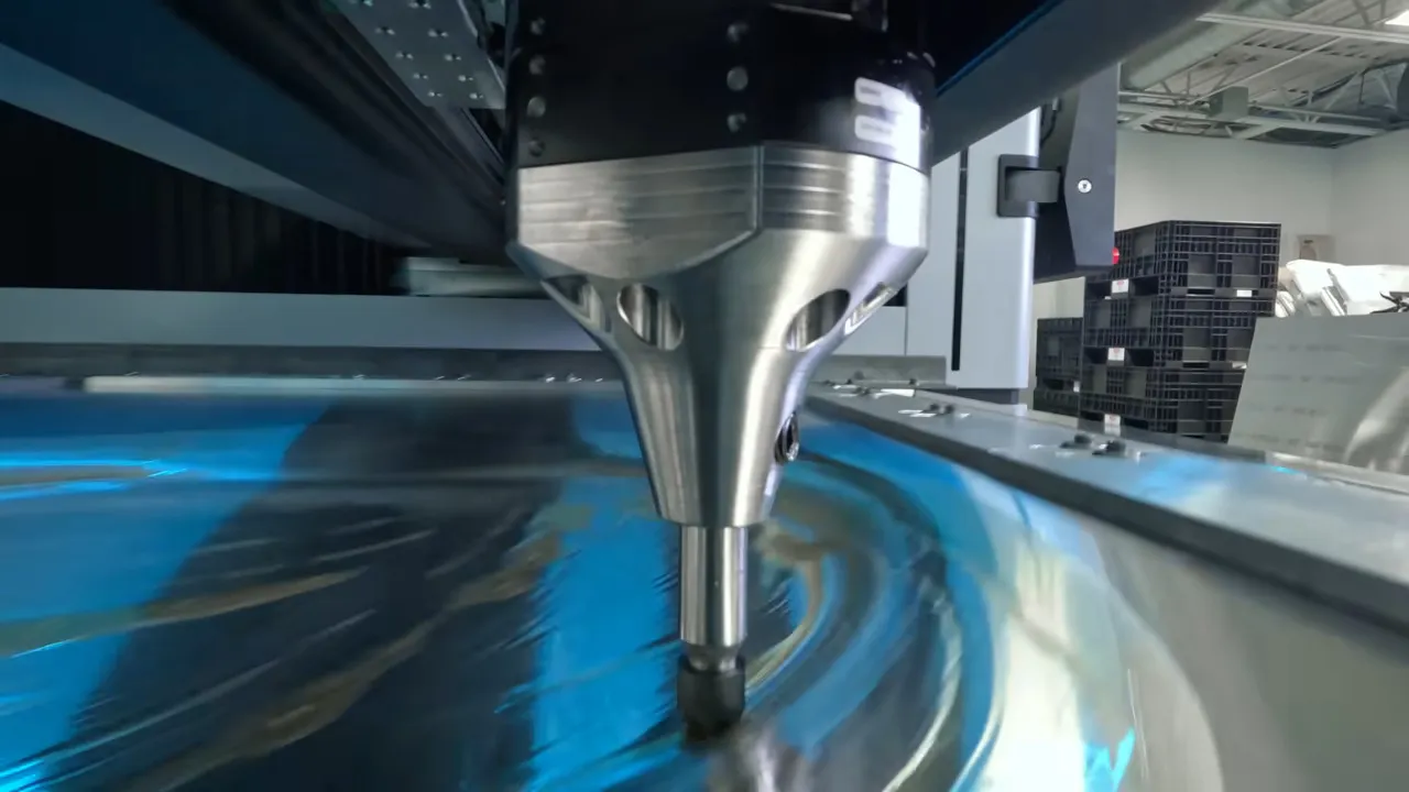
การตัดด้วยเลเซอร์ได้กลายเป็นเทคโนโลยีหลักที่ให้ความแม่นยำสูงในการผลิตชิ้นส่วนโลหะแผ่นในยุคปัจจุบัน ลำแสงเลเซอร์ที่มีความเข้มสูง—ควบคุมด้วยเทคโนโลยี CNC (การควบคุมตัวเลขด้วยคอมพิวเตอร์)—จะทำให้วัสดุระเหิดหรือหลอมละลายตามเส้นทางที่โปรแกรมไว้ ซึ่งให้รอยตัดที่มีความแม่นยำสูงมากและเกิดการบิดงอจากความร้อนน้อยที่สุด
CNC ย่อมาจากอะไรในเชิงปฏิบัติ? หมายความว่าแบบจำลอง CAD ของคุณจะถูกแปลงโดยตรงเป็นคำสั่งสำหรับเครื่องจักร ซึ่งช่วยขจัดข้อผิดพลาดที่เกิดจากการตั้งค่าด้วยตนเอง และรับประกันความสม่ำเสมอในการผลิตชิ้นส่วนได้ทั้งร้อยหรือพันชิ้น
ตามการวิเคราะห์กระบวนการผลิตของ UD Machine ระบบที่ใช้เลเซอร์รุ่นใหม่ร่วมกับเทคโนโลยีแมชชีนเลิร์นนิงและการวิเคราะห์ข้อมูลแบบเรียลไทม์สามารถปรับแต่งเส้นทางการตัดและอัตราการใช้พลังงานโดยอัตโนมัติ ลดของเสียจากวัสดุลงพร้อมยกระดับประสิทธิภาพในการดำเนินงาน
วิธีการตัดด้วยเลเซอร์หลักสามแบบ ถูกออกแบบมาเพื่อรองรับวัสดุและข้อกำหนดที่แตกต่างกัน
- การตัดแบบฟิวชัน: ใช้ก๊าซเฉื่อย (ไนโตรเจนหรืออาร์กอน) พ่นออกไปเพื่อขจัดวัสดุที่ละลาย ทำให้ได้รอยตัดคุณภาพสูงบนโลหะ เช่น โครเมียมและอะลูมิเนียม โดยแทบไม่มีการเกิดออกซิเดชันเลย — เหมาะอย่างยิ่งเมื่อคุณภาพผิวและความแม่นยำสูงเป็นสิ่งสำคัญที่สุด
- การตัดแบบฟลาม ป้อนออกซิเจนระหว่างการตัด เพื่อสร้างความร้อนเพิ่มเติมผ่านปฏิกิริยากับวัสดุที่มีธาตุเหล็ก — มีประสิทธิภาพสูงสำหรับแผ่นเหล็กคาร์บอนต่ำที่มีความหนา แม้ว่าขอบของชิ้นงานมักจำเป็นต้องผ่านกระบวนการตกแต่งเพิ่มเติมหลังการตัด เนื่องจากการเกิดออกซิเดชัน
- การตัดแบบซับลิเมชัน: เปลี่ยนวัสดุโดยตรงจากของแข็งเป็นไอโดยไม่ผ่านสถานะของเหลว — โดยทั่วไปใช้กับวัสดุที่ไม่ใช่โลหะ เช่น พลาสติกและเซรามิก ซึ่งช่วยให้สามารถสร้างลวดลายที่ซับซ้อนได้โดยไม่ทำลายบริเวณใกล้เคียง
ข้อได้เปรียบหลักของการตัดด้วยเลเซอร์สำหรับงานความแม่นยำสูง:
- ความกว้างของรอยตัด (kerf width) แคบมาก (มักอยู่ระหว่าง 0.004 นิ้ว ถึง 0.015 นิ้ว) ทำให้สามารถสร้างรายละเอียดที่ประณีตและสูญเสียวัสดุน้อยที่สุด
- เขตที่ได้รับผลกระทบจากความร้อน (heat-affected zone) มีขนาดเล็กมาก จึงรักษาคุณสมบัติของวัสดุบริเวณขอบรอยตัดไว้ได้
- ไม่มีการสัมผัสโดยเครื่องมือทางกายภาพ จึงไม่เกิดการบิดเบี้ยวเชิงกลกับชิ้นส่วนที่บอบบาง
- สามารถเขียนโปรแกรมควบคุมได้สูงมาก จึงเหมาะสำหรับรูปทรงเรขาคณิตที่ซับซ้อนและแบบที่ไม่ซ้ำกัน
- ขอบรอยตัดที่สะอาดมักไม่จำเป็นต้องผ่านกระบวนการตกแต่งเพิ่มเติม
- เลเซอร์ไฟเบอร์สามารถตัดแผ่นโลหะได้หนาสูงสุดถึง 30 มม. ขึ้นอยู่กับการจัดวางกำลังงาน
ความคลาดเคลื่อนในการตัดด้วยเลเซอร์โดยทั่วไปอยู่ที่ ±0.005 นิ้ว หรือดีกว่านั้น สำหรับวัสดุส่วนใหญ่ — จึงเป็นตัวเลือกอันดับหนึ่งเมื่อความแม่นยำด้านมิติเป็นปัจจัยหลักที่กำหนดความต้องการของโครงการคุณ
การเจาะด้วย CNC สำหรับความแม่นยำที่ทำซ้ำได้
แม้ว่าการตัดด้วยเลเซอร์จะครองตลาดงานที่ต้องการความแม่นยำสูง แต่การเจาะด้วยเครื่อง CNC ยังคงมีความจำเป็นอย่างยิ่งสำหรับการผลิตชิ้นส่วนจำนวนมากที่มีลักษณะซ้ำๆ กัน เครื่องเจาะใช้แรงกลหรือแรงไฮดรอลิกในการดันหัวเจาะผ่านแผ่นโลหะเข้าสู่แม่พิมพ์ (die) เพื่อสร้างรูหรือรูปร่างต่างๆ ภายในหนึ่งจังหวะที่รวดเร็ว
ระบบการเจาะด้วยหัวหมุน CNC แบบทันสมัยผสานการควบคุมด้วยคอมพิวเตอร์เชิงตัวเลข (CNC) เข้ากับหัวหมุนเครื่องมือที่สามารถหมุนเปลี่ยนเครื่องมือได้ ซึ่งบรรจุชุดหัวเจาะและแม่พิมพ์หลายชุดไว้ด้วยกัน โครงสร้างนี้ช่วยให้สามารถเปลี่ยนเครื่องมือได้อย่างรวดเร็วโดยไม่ต้องหยุดการผลิต — ซึ่งมีความสำคัญอย่างยิ่งเมื่อชิ้นส่วนต้องการรูที่มีขนาด รูปร่าง หรือลักษณะการขึ้นรูปที่หลากหลาย
ข้อได้เปรียบหลักของการเจาะด้วยเครื่อง CNC:
- ความเร็วสูงมากสำหรับชิ้นส่วนที่ต้องมีรูจำนวนมากและรูปร่างเรียบง่าย
- ความเที่ยงตรงซ้ำได้สูงตลอดการผลิตจำนวนมาก
- ต้นทุนต่อชิ้นต่ำกว่าการตัดด้วยเลเซอร์สำหรับรูปร่างทั่วไป
- สามารถดำเนินการปฏิบัติการขั้นที่สอง (เช่น การนูน การขึ้นรูป และการตอกเกลียว) ได้แบบต่อเนื่องในสายการผลิต
- การจัดวางชิ้นส่วนอย่างมีประสิทธิภาพ (nesting) ช่วยลดของเสียจากวัสดุให้น้อยที่สุด
- คุณภาพสม่ำเสมอโดยไม่มีผลกระทบจากความร้อนต่อคุณสมบัติของวัสดุ
การตัดโลหะด้วยวิธีการเจาะ (punching) จะขจัดวัสดุออกโดยอาศัยแรงกล แทนที่จะหลอมวัสดุ ซึ่งส่งผลให้ขอบของชิ้นงานมีลักษณะต่างออกไปเมื่อเทียบกับการตัดด้วยเลเซอร์ วิธีการเชิงกลนี้ทำให้เกิดโซนที่ได้รับผลกระทบจากความร้อน (heat-affected zone) น้อยมาก หรือแทบไม่มีเลย ซึ่งเป็นข้อได้เปรียบเมื่อคุณสมบัติของวัสดุจำเป็นต้องคงเดิมบริเวณขอบที่ถูกตัด
อย่างไรก็ตาม วิธีการเจาะมีข้อจำกัดบางประการ รูปทรงเรขาคณิตที่ซับซ้อนจำเป็นต้องใช้การเจาะหลายครั้ง หรือต้องใช้แม่พิมพ์เฉพาะทาง วัสดุที่บางมากอาจเกิดการบิดเบี้ยวภายใต้แรงกดของหัวเจาะ และรูปร่างที่ซับซ้อนซึ่งเลเซอร์สามารถตัดได้อย่างง่ายดาย อาจไม่สามารถตัดด้วยวิธีเจาะได้เลย หรือหากทำได้ก็อาจไม่คุ้มค่าทางปฏิบัติ
ตามการวิเคราะห์ของอุตสาหกรรม กระบวนการทำงานแบบผสมผสาน (hybrid fabrication workflows) ที่รวมทั้งสองวิธีเข้าด้วยกันกำลังได้รับความนิยมเพิ่มขึ้นอย่างต่อเนื่อง ผู้ผลิตจึงใช้ความเร็วของการเจาะสำหรับฟีเจอร์ที่ต้องทำซ้ำบ่อย ๆ ขณะเดียวกันก็ใช้ความแม่นยำของเลเซอร์สำหรับองค์ประกอบที่ออกแบบมาเฉพาะหรือมีความซับซ้อน เพื่อเพิ่มประสิทธิภาพทั้งในด้านความรวดเร็วและความแม่นยำ
วิธีการดัดและขึ้นรูปที่รักษาความแม่นยำไว้
การตัดจะสร้างชิ้นงานที่มีรูปทรงแบนราบ การดัดจะเปลี่ยนชิ้นงานเหล่านั้นให้กลายเป็นองค์ประกอบสามมิติ และนี่คือจุดที่โครงการความแม่นยำจำนวนมากประสบความสำเร็จหรือล้มเหลว
การดัดด้วยเครื่องกดดัด (Press brake bending) ใช้หัวดัด (punch) และแม่พิมพ์ (die) เพื่อสร้างรอยดัดที่ควบคุมได้บนแผ่นโลหะ ตามมุมและตำแหน่งที่กำหนดไว้ ขั้นตอนนี้อาจฟังดูง่าย แต่การบรรลุความแม่นยำของมุมอย่างสม่ำเสมอจำเป็นต้องเข้าใจพฤติกรรมของวัสดุ การเลือกเครื่องมือ และการปรับเทียบเครื่องจักร
ปัจจัยสำคัญในการดัดแผ่นเหล็กแบบความแม่นยำสูง:
- การชดเชยการเด้งกลับ วัสดุทุกชนิดมีแนวโน้มที่จะคืนรูปบางส่วนกลับสู่รูปร่างเดิมหลังการดัด — วัสดุที่มีความแข็งแรงสูงจะคืนรูปมากกว่า จึงจำเป็นต้องดัดเกินมุมเป้าหมาย (overbending) เพื่อให้ได้มุมที่ต้องการ
- การเลือกรัศมีการดัด: รัศมีการดัดด้านในต่ำสุดโดยทั่วไปเท่ากับความหนาของวัสดุสำหรับโลหะผสมส่วนใหญ่ — การเลือกรัศมีที่แคบกว่านี้อาจทำให้เกิดรอยร้าวหรือความหนาของวัสดุลดลงอย่างมาก
- ทิศทางของเส้นใย: การดัดในแนวตั้งฉากกับทิศทางของเม็ดเกรนจากการรีด (rolling grain) จะช่วยลดความเสี่ยงของการเกิดรอยร้าว และปรับปรุงคุณภาพของขอบที่ผ่านการขึ้นรูปแล้ว
- ลำดับการดัด: ชิ้นส่วนที่ซับซ้อนต้องมีการจัดลำดับขั้นตอนการปฏิบัติงานอย่างระมัดระวัง เพื่อหลีกเลี่ยงการชนกันระหว่างชิ้นงานและอุปกรณ์เครื่องมือ
ข้อได้เปรียบสำคัญของการขึ้นรูปด้วยเครื่องกดโค้ง (press brake):
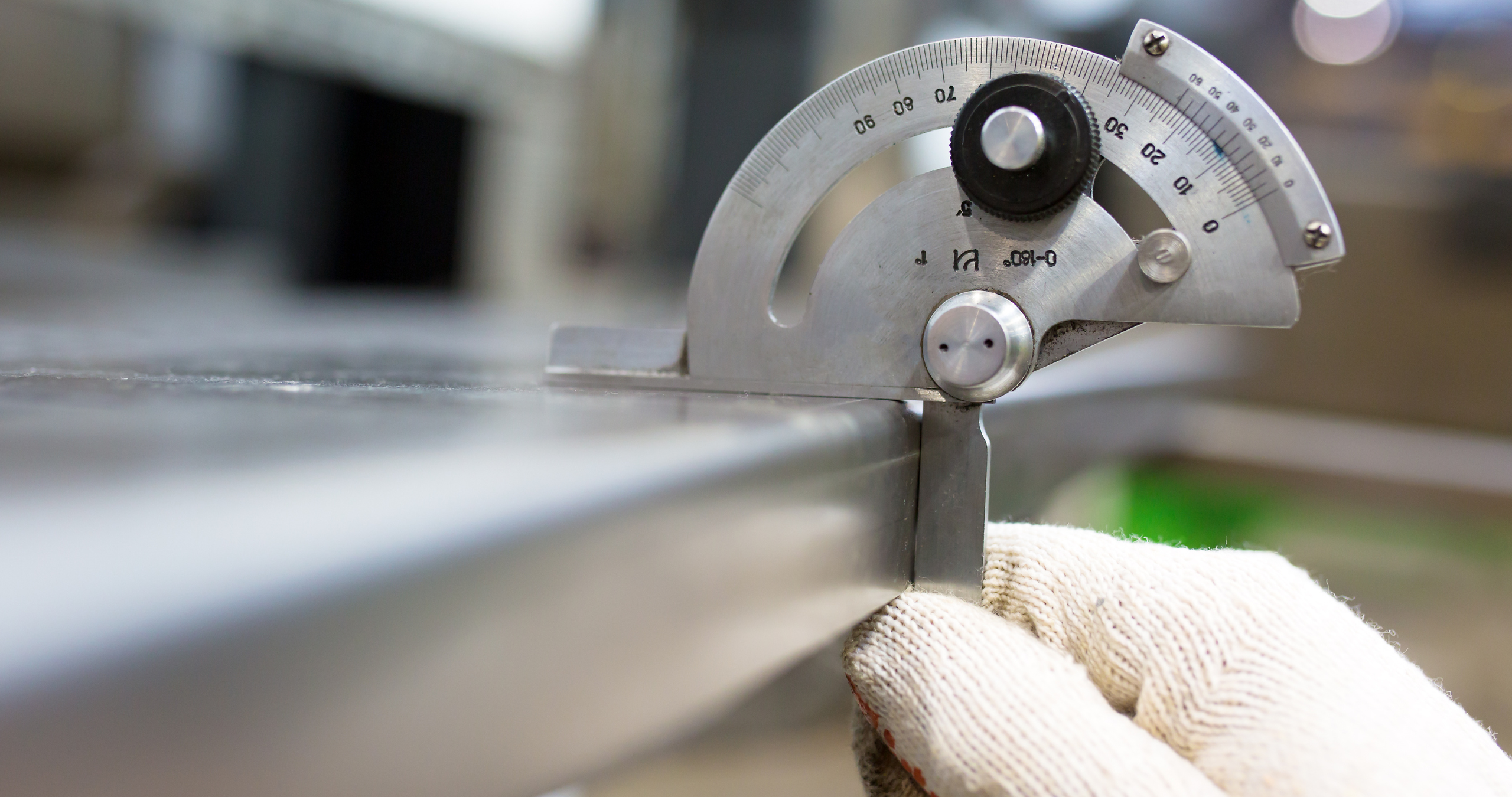
- ความแม่นยำเชิงมุมภายใน ±0.5° สามารถทำได้ด้วยการตั้งค่าและการสอบเทียบที่เหมาะสม
- ความคลาดเคลื่อนด้านมิติ ±0.015 นิ้ว ที่ตำแหน่งการโค้ง
- ช่วงมุมการโค้งที่กว้าง ตั้งแต่เส้นโค้งแบบนุ่มนวลไปจนถึงมุมฉากที่คมชัด 90°
- ความสามารถในการขึ้นรูปเรขาคณิตที่มีหลายจุดโค้งซับซ้อนในครั้งเดียวโดยไม่ต้องเปลี่ยนการตั้งค่า
- ระบบตัววัดย้อนกลับแบบ CNC (CNC backgauges) รับประกันความแม่นยำในการจัดตำแหน่งซ้ำได้ตลอดการผลิต
นอกเหนือจากการโค้งแบบมาตรฐานแล้ว การดำเนินการขึ้นรูปเพิ่มเติมยังช่วยขยายขอบเขตของสิ่งที่สามารถทำได้กับแผ่นโลหะแบน:
- การขึ้นรูปด้วยลูกกลิ้ง: สร้างรูปทรงโค้งแบบต่อเนื่องโดยให้วัสดุผ่านสถานีลูกกลิ้งแบบลำดับขั้นตอน
- การตัด/ดัด (Stamping): รวมการตัดและการขึ้นรูปไว้ในหนึ่งจังหวะการทำงาน เพื่อการผลิตปริมาณสูง
- ไฮโดรฟอร์มมิ่ง: ใช้ความดันของของไหลในการขึ้นรูปชิ้นส่วนที่มีรูปร่างซับซ้อนโดยมีความหนาของผนังสม่ำเสมอ
ความสัมพันธ์ระหว่างกระบวนการตัดและการขึ้นรูปมีผลโดยตรงต่อความแม่นยำที่สามารถบรรลุได้ ชิ้นงานที่ถูกตัดด้วยเลเซอร์ซึ่งมีความคลาดเคลื่อนเชิงมิติแคบจะถูกป้อนเข้าสู่กระบวนการดัดได้อย่างสม่ำเสมอมากกว่าชิ้นงานที่ถูกตัดแบบหยาบ ในทำนองเดียวกัน การวางแผนลำดับการดัดอย่างเหมาะสมจะช่วยให้การดัดในขั้นตอนแรกไม่รบกวนการดำเนินการหรือจุดอ้างอิงสำหรับการวัดในขั้นตอนถัดไป
การเข้าใจขีดความสามารถของแต่ละกระบวนการ—รวมถึงปฏิสัมพันธ์ระหว่างกัน—จะช่วยให้คุณออกแบบชิ้นส่วนที่สามารถใช้จุดแข็งของแต่ละวิธีได้อย่างเต็มที่ เมื่อได้ครอบคลุมหลักการพื้นฐานของการตัดและการขึ้นรูปแล้ว คุณก็พร้อมที่จะศึกษาข้อกำหนดเฉพาะเกี่ยวกับค่าความคลาดเคลื่อน (tolerance) และขีดจำกัดของความแม่นยำ ซึ่งจะกำหนดขอบเขตสิ่งที่สามารถทำได้ในโครงการต่อไปของคุณ
คำอธิบายเกี่ยวกับข้อกำหนดความคลาดเคลื่อนและขีดจำกัดของความแม่นยำ
คุณได้เรียนรู้เกี่ยวกับวัสดุและกระบวนการผลิตแล้ว แต่คำถามที่จะกำหนดว่าชิ้นส่วนของคุณใช้งานได้จริงหรือไม่คือ: คุณสามารถควบคุมความคลาดเคลื่อน (tolerance) ได้แม่นยำในระดับใดอย่างสมจริง? การเข้าใจข้อกำหนดด้านความคลาดเคลื่อนเป็นสิ่งที่แยกแยะโครงการที่ประสบความสำเร็จออกจากโครงการที่ต้องออกแบบใหม่ซึ่งส่งผลให้เกิดค่าใช้จ่ายสูง และชิ้นส่วนที่ถูกปฏิเสธ
ความคลาดเคลื่อนไม่ใช่ตัวเลขที่กำหนดขึ้นแบบพลการ — แต่เป็นจุดตัดกันระหว่างความสามารถของกระบวนการผลิต พฤติกรรมของวัสดุ และข้อกำหนดด้านการออกแบบ การระบุความคลาดเคลื่อนที่หละหลวมเกินไปจะนำไปสู่ปัญหาในการประกอบ ในขณะที่การระบุความคลาดเคลื่อนที่แน่นเกินไปจะทำให้ต้นทุนเพิ่มขึ้นโดยไม่จำเป็น การหาจุดสมดุลที่เหมาะสมนั้นต้องอาศัยความรู้ว่าแต่ละกระบวนการสามารถบรรลุความคลาดเคลื่อนได้ในระดับใด และเข้าใจปัจจัยต่าง ๆ ที่มีอิทธิพลต่อขีดจำกัดเหล่านั้น
การเข้าใจสัญลักษณ์แสดงความคลาดเคลื่อนและความหมายของมัน
ก่อนที่จะลงลึกถึงตัวเลขเฉพาะ ขอชี้แจงความหมายของการระบุค่าความคลาดเคลื่อน (tolerance notation) ก่อนว่าสื่อความหมายอะไรจริง ๆ เมื่อคุณเห็นขนาดที่เขียนไว้ว่า 2.500" ±0.005" นั่นหมายถึงค่าที่กำหนดไว้เป็นมาตรฐาน (nominal value) ซึ่งเท่ากับ 2.500" บวกกับช่วงความแปรผันที่ยอมรับได้ (ทั้งในทางบวกและลบ ห้าพันส่วนหนึ่งของนิ้ว)
ซึ่งหมายความว่าชิ้นส่วนสำเร็จรูปของคุณอาจมีขนาดอยู่ระหว่าง 2.495" ถึง 2.505" ก็ยังผ่านการตรวจสอบได้ ช่วงความแปรผันที่ยอมรับได้ทั้งหมดนี้ — ในกรณีนี้คือ 0.010" — คือ "หน้าต่างความคลาดเคลื่อน (tolerance window)" ของคุณ
ด้านต่าง ๆ ของชิ้นส่วนของคุณจำเป็นต้องใช้ประเภทความคลาดเคลื่อนที่แตกต่างกัน:
- ความคลาดเคลื่อนทางมิติ: ควบคุมความแปรผันของความยาว ความกว้าง การจัดตำแหน่งรู และตำแหน่งของลักษณะต่าง ๆ
- ความคลาดเคลื่อนเชิงมุม: กำกับความเบี่ยงเบนที่ยอมรับได้จากมุมการดัดที่ระบุไว้ โดยทั่วไปแสดงเป็นองศา
- ความคลาดเคลื่อนของความหนา: คำนึงถึงความแปรผันโดยธรรมชาติของความหนาของวัสดุดิบซึ่งเกิดขึ้นจากกระบวนการรีด (rolling process)
- ความคลาดเคลื่อนด้านความเรียบ จัดการกับความโค้งงอ ความโก่ง หรือความเป็นคลื่นที่ยอมรับได้ ซึ่งเกิดขึ้นจากพื้นผิวที่ควรจะเรียบสนิท
เช่นเดียวกับแผนภูมิขนาดดอกสว่านหรือแผนภูมิขนาดสว่านที่ช่วยให้ช่างกลไกเลือกเครื่องมือที่เหมาะสมสำหรับความต้องการเจาะรูเฉพาะเจาะจง ข้อกำหนดด้านความคลาดเคลื่อน (tolerance) ก็ทำหน้าที่ชี้นำผู้ผลิตชิ้นส่วนให้เลือกกระบวนการและพารามิเตอร์การตั้งค่าที่เหมาะสมตามความต้องการด้านความแม่นยำของคุณ
ขีดจำกัดความแม่นยำเฉพาะต่อกระบวนการ
แต่ละวิธีการผลิตชิ้นส่วนมีศักยภาพด้านความแม่นยำในตัวเอง การเข้าใจขีดจำกัดเหล่านี้จะช่วยให้คุณสามารถจับคู่ข้อกำหนดด้านความคลาดเคลื่อนของคุณกับกระบวนการที่เหมาะสม — และหลีกเลี่ยงการระบุขนาดที่ไม่สามารถควบคุมให้คงที่ได้จริง
ตามข้อกำหนดด้านความคลาดเคลื่อนของ Komacut ต่อไปนี้คือความคลาดเคลื่อนที่สามารถบรรลุได้ในการดำเนินการแผ่นโลหะทั่วไป:
| กระบวนการ | ความคลาดเคลื่อนมาตรฐาน | ความทนทานในระดับความแม่นยำสูง | หมายเหตุ |
|---|---|---|---|
| การตัดด้วยเลเซอร์ – แนวเส้นตรง | ±0.45 มม. (±0.018 นิ้ว) | ±0.20 มม. (±0.008 นิ้ว) | สามารถบรรลุความคลาดเคลื่อนที่แคบยิ่งขึ้นได้ด้วยการตั้งค่าพิเศษ |
| การตัดด้วยเลเซอร์ – เส้นผ่านศูนย์กลางรู | ±0.45 มม. (±0.018 นิ้ว) | ±0.08 มม. (±0.003 นิ้ว) | คุณภาพของรูขึ้นอยู่กับความหนาของวัสดุ |
| Cnc punching | ±0.25 มม. (±0.010 นิ้ว) | ±0.10 มม. (±0.004 นิ้ว) | มีความสามารถในการทำซ้ำได้อย่างยอดเยี่ยมสำหรับการผลิตจำนวนมาก |
| การดัด – มุม | ±1.0° | ±0.5° | การชดเชยแรงเด้งกลับมีความสำคัญอย่างยิ่งต่อความแม่นยำ |
| การดัด – มิติ XYZ | ±0.45 มม. (±0.018 นิ้ว) | ±0.20 มม. (±0.008 นิ้ว) | ตำแหน่งของอุปกรณ์วัดย้อนกลับส่งผลต่อความสามารถในการทำซ้ำ |
สำหรับข้อกำหนดที่เกี่ยวข้องกับความหนา ประเภทของวัสดุมีผลอย่างมากต่อความสม่ำเสมอที่สามารถบรรลุได้ ตารางขนาดแผ่นโลหะ (gauge chart) แสดงให้เห็นว่าขนาดมาตรฐานตามระบบ gauge แปลงเป็นความหนาเฉพาะเจาะจง — แต่ความหนาจริงของวัสดุอาจแปรผันภายในช่วงความคลาดเคลื่อนที่ยอมรับได้ แผ่นเหล็กที่ผ่านการรีดเย็น (cold-rolled steel) มีการควบคุมความหนาที่แม่นยำกว่าแผ่นเหล็กที่ผ่านการรีดร้อน (hot-rolled steel)
นี่คือสิ่งที่คุณสามารถคาดหวังได้สำหรับวัสดุทั่วไป โดยอ้างอิงจากมาตรฐานความคลาดเคลื่อนของอุตสาหกรรม:
- SPCC Cold Rolled Steel (1.0–1.2 มม.): ความคลาดเคลื่อนของความหนา ±0.08 มม. สำหรับแผ่นที่มีความกว้างน้อยกว่า 1000 มม.
- อลูมิเนียม (1.0–1.2 มม.): ความคลาดเคลื่อน ±0.04 มม. ถึง ±0.07 มม. ขึ้นอยู่กับความกว้างของแผ่น
- สแตนเลสสตีล (1.0–1.5 มม.): ความคลาดเคลื่อน ±0.035 มม. ถึง ±0.040 มม. สำหรับวัสดุเกรดพรีซิชัน
เมื่อทำงานกับขนาดเกจ (gauge) โปรดทราบว่า เหล็กเกจเบอร์ 14 มีความหนาโดยประมาณ 0.075 นิ้ว (1.9 มม.) ในขณะที่เหล็กเกจเบอร์ 11 มีความหนาโดยประมาณ 0.120 นิ้ว (3.0 มม.) ตารางอ้างอิงขนาดเกจเหล่านี้ช่วยให้คุณระบุวัสดุได้อย่างถูกต้อง แต่ควรยืนยันขอบเขตความคลาดเคลื่อนที่แท้จริงกับผู้จัดจำหน่ายเสมอ
ปัจจัยที่มีผลต่อความคลาดเคลื่อนที่สามารถบรรลุได้
ความสามารถในการควบคุมความคลาดเคลื่อนไม่ใช่ค่าคงที่ — แต่จะเปลี่ยนแปลงไปตามปัจจัยหลายประการที่มีปฏิสัมพันธ์กัน ดังนั้น การเข้าใจตัวแปรเหล่านี้จะช่วยให้คุณออกแบบชิ้นส่วนให้อยู่ภายในขอบเขตที่สามารถบรรลุได้จริง
คุณสมบัติของวัสดุมีผลอย่างมาก ตามข้อมูลอุตสาหกรรม แผ่นเหล็กที่ผ่านการรีดร้อนมีความแปรปรวนของความหนาค่อนข้างมาก เนื่องจากการเย็นตัวหลังการรีด ในขณะที่เหล็กที่ผ่านการรีดเย็นสามารถควบคุมความหนาได้แม่นยำยิ่งกว่า วัสดุที่นุ่มกว่า เช่น อลูมิเนียมและทองแดง จะขึ้นรูปได้สม่ำเสมอกว่า แต่อาจจำเป็นต้องใช้การรองรับเพิ่มเติมระหว่างกระบวนการเพื่อป้องกันการบิดเบี้ยว
ข้อจำกัดเชิงเรขาคณิตกำหนดขีดจำกัดเชิงปฏิบัติ เมื่อปรึกษาตารางเจาะรูสำหรับข้อกำหนดของรู โปรดทราบว่าการผลิตชิ้นส่วนโลหะแผ่นมีกฎเกณฑ์เชิงเรขาคณิตที่คล้ายคลึงกัน:
- ระยะห่างต่ำสุดจากรูถึงแนวพับ: หากวางรูใกล้กับแนวพับมากเกินไป รูจะบิดเบี้ยวระหว่างขั้นตอนการขึ้นรูป — จึงควรเว้นระยะห่างที่เหมาะสมตามความหนาของวัสดุและรัศมีการพับ
- ความสูงขอบต่ำสุด: ขอบของฟลานจ์ต้องยื่นออกพ้นแนวพับให้เพียงพอ เพื่อให้สามารถเข้ากับเครื่องมือได้อย่างเหมาะสม ตามที่ระบุไว้ในแนวทางรัศมีการพับของบริษัท Protocase
- ระยะห่างจากหลุมถึงขอบ: ลักษณะต่าง ๆ ที่อยู่ใกล้ขอบแผ่นโลหะมากเกินไปอาจเกิดการบิดเบี้ยวระหว่างขั้นตอนการตัดหรือการจัดการ
- ข้อจำกัดของรัศมีการพับ: รัศมีการพับด้านในต่ำสุดโดยทั่วไปเท่ากับความหนาของวัสดุ — การพับด้วยรัศมีที่เล็กลงกว่านี้อาจทำให้วัสดุแตกร้าว
ช่วงความหนาของวัสดุมีผลต่อการเลือกกระบวนการ งานแผ่นโลหะความแม่นยำส่วนใหญ่จะอยู่ในช่วง 0.020 นิ้ว ถึง 0.250 นิ้ว (0.5 มม. ถึง 6.0 มม.) วัสดุที่บางกว่านี้อาจต้องการการจัดการเป็นพิเศษเพื่อป้องกันการบิดเบี้ยว ในขณะที่วัสดุที่หนากว่านี้จะจำกัดรัศมีการดัดที่ทำได้ และอาจจำเป็นต้องใช้วิธีการตัดแบบอื่น
ความคลาดเคลื่อนสะสมทำให้ข้อผิดพลาดเพิ่มขึ้น ในการประกอบชิ้นส่วนที่มีลักษณะขึ้นรูปหลายจุด ความแปรผันเล็กน้อยในแต่ละขั้นตอนการผลิตจะสะสมเข้าด้วยกัน ตัวอย่างเช่น ชิ้นส่วนที่มีรอยพับห้าจุด โดยแต่ละจุดมีความคลาดเคลื่อนไม่เกิน ±0.5° อาจเบี่ยงเบนจากค่าที่ตั้งไว้ได้สูงสุดถึง 2.5° ที่จุดสุดท้ายของลักษณะขึ้นรูป ผู้ผลิตที่มีประสบการณ์จะจัดลำดับขั้นตอนการผลิตและกำหนดจุดอ้างอิง (datum references) เพื่อลดผลกระทบจากการสะสมความคลาดเคลื่อนนี้
ปัจจัยด้านสิ่งแวดล้อมและอุปกรณ์ก็มีบทบาทเช่นกัน:
- การสอบเทียบเครื่องจักรและสถานะการบำรุงรักษา
- การสึกหรอและสภาพของแม่พิมพ์/อุปกรณ์
- อุณหภูมิแวดล้อมที่ส่งผลต่อพฤติกรรมของวัสดุ
- ทักษะของผู้ปฏิบัติงานสำหรับกระบวนการที่ทำด้วยมือ
ประเด็นสำคัญที่ควรจดจำคือ? ค่าความคลาดเคลื่อน (tolerances) สะท้อนถึงความสามารถในระดับระบบโดยรวม ไม่ใช่เพียงข้อกำหนดเฉพาะของเครื่องจักรเท่านั้น การทำงานร่วมกับผู้ผลิตชิ้นส่วนที่มีประสบการณ์ซึ่งเข้าใจถึงการแลกเปลี่ยนด้านต่าง ๆ เหล่านี้ และสามารถปรับแต่งการออกแบบชิ้นส่วนให้เหมาะสมเพื่อลดปัญหาการสะสมของค่าความคลาดเคลื่อน (tolerance stack-up) นั้น ส่งผลอย่างวัดได้ต่อความแม่นยำและคุณภาพโดยรวม
เมื่อคุณเข้าใจแล้วว่าค่าความคลาดเคลื่อนใดบ้างที่สามารถทำได้จริง คุณก็พร้อมที่จะเรียนรู้ว่าการตัดสินใจด้านการออกแบบของคุณส่งผลโดยตรงต่อทั้งผลลัพธ์ด้านความแม่นยำและต้นทุนการผลิตอย่างไร
หลักการออกแบบเพื่อความสามารถในการผลิต (Design for Manufacturability Principles)
นี่คือข้อเท็จจริงที่ควรรับรู้: แม้แต่อุปกรณ์การผลิตขั้นสูงที่สุดก็ไม่สามารถช่วยชิ้นส่วนที่ออกแบบมาไม่ดีให้รอดพ้นจากปัญหาได้ การตัดสินใจด้านการออกแบบของคุณ—ซึ่งเกิดขึ้นตั้งแต่ระยะแรกเริ่ม ก่อนที่โลหะจะสัมผัสกับเครื่องจักรแม้แต่ครั้งเดียว—เป็นตัวกำหนดว่าโครงการของคุณจะดำเนินไปอย่างราบรื่น หรือหยุดชะงักลงด้วยการแก้ไขที่มีค่าใช้จ่ายสูง
การออกแบบเพื่อความสะดวกในการผลิต (Design for Manufacturability: DFM) เป็นแนวทางที่เชื่อมช่องว่างระหว่างสิ่งที่คุณจินตนาการไว้กับสิ่งที่ผู้ผลิตชิ้นส่วนสามารถผลิตออกมาได้อย่างมีประสิทธิภาพจริง ๆ ตาม ข้อมูลเชิงลึกด้านการผลิตของ IMS Manufacturing การตัดสินใจเล็กๆ ในการออกแบบมีผลลัพธ์ที่ใหญ่หลวงต่องานขึ้นรูปแผ่นโลหะ รูที่เจาะผิดตำแหน่ง รัศมีการดัดที่ละเลยไป หรือค่าความคลาดเคลื่อนที่แคบเกินไป อาจทำให้การผลิตหยุดชะงักหรือเพิ่มต้นทุนได้
ข่าวดีก็คือ การนำหลักการ DFM ที่พิสูจน์แล้วว่าได้ผลมาประยุกต์ใช้ตั้งแต่ช่วงต้นของกระบวนการวิศวกรรมแผ่นโลหะ จะช่วยป้องกันปัญหาเหล่านี้ไว้ได้ พร้อมทั้งเพิ่มประสิทธิภาพทั้งในด้านความแม่นยำและความคุ้มค่าด้านต้นทุน
การออกแบบเพื่อการผลิตในงานแผ่นโลหะ
การขึ้นรูปแผ่นโลหะไม่เหมือนกับการออกแบบสำหรับการฉีดพลาสติก การหล่อ หรือการพิมพ์สามมิติ ซึ่งมีข้อจำกัดเฉพาะตัว เช่น ค่าเผื่อการดัด ทิศทางของเม็ดเกรน (grain direction) ระยะว่างของเครื่องมือ และเรขาคณิตของแบบแปลนแผ่นเรียบ (flat pattern) ซึ่งส่งผลโดยตรงต่อวิธีการขึ้นรูป ตัด และประกอบชิ้นส่วนของคุณ
การเพิกเฉยต่อรายละเอียดเหล่านี้จะนำไปสู่การชะลอการผลิต ของเสียจากวัสดุ หรือปัญหาด้านคุณภาพ นี่จึงเป็นเหตุผลสำคัญที่ DFM มีความสำคัญอย่างยิ่งในโครงการขึ้นรูปแผ่นโลหะตามสั่ง: คุณกำลังออกแบบชิ้นส่วนที่ไม่เพียงแต่ทำงานตามวัตถุประสงค์เท่านั้น แต่ยังสามารถผสานเข้ากับกระบวนการขึ้นรูปได้อย่างราบรื่นอีกด้วย
ไม่ว่าคุณจะกำลังพัฒนาต้นแบบชิ้นส่วนโลหะแผ่น หรือเตรียมความพร้อมสำหรับการผลิตเต็มรูปแบบ หลักการพื้นฐานเหล่านี้ล้วนใช้ได้ทั่วไป:
- ให้รัศมีด้านในของการโค้ง (Inside Bend Radius) สอดคล้องกับความหนาของวัสดุ หลักทั่วไปที่ดี: รัศมีด้านในของการโค้งควรเท่ากับความหนาของวัสดุ ถ้าต้องการโค้งที่แคบกว่านั้น อาจจำเป็นต้องใช้อุปกรณ์พิเศษ หรืออาจทำให้วัสดุแตกร้าว—โดยเฉพาะวัสดุที่แข็ง เช่น สแตนเลส
- รักษาระยะห่างที่เพียงพอระหว่างรูและเส้นโค้ง ปฏิบัติตามกฎ 4T: คุณลักษณะและองค์ประกอบทั้งหมดควรอยู่ห่างจากเส้นโค้งอย่างน้อยสี่เท่าของความหนาของวัสดุ การเจาะรูใกล้เกินไปจะทำให้เกิดการบิดตัวหรือเปลี่ยนรูปร่างอย่างแน่นอนระหว่างขั้นตอนการขึ้นรูป
- เคารพระยะห่างขั้นต่ำระหว่างรูกับขอบแผ่น คุณลักษณะที่วางไว้ใกล้ขอบแผ่นมากเกินไปอาจเกิดการบิดตัวระหว่างการตัด การจัดการ หรือขั้นตอนอื่นๆ ที่ตามมา ดังนั้นควรมีระยะว่างเพียงพอสำหรับการยืดตัวของวัสดุและการเข้าถึงของเครื่องมือ
- พิจารณาทิศทางของเม็ดเกรน (Grain Direction) สำหรับการโค้ง การดัดในแนวตั้งฉากกับทิศทางของเมล็ดวัสดุ (rolling grain) จะช่วยลดความเสี่ยงของการแตกร้าว และปรับปรุงคุณภาพของขอบที่ขึ้นรูปได้ดีขึ้น ดังนั้น ควรวางรูปแบบแผ่นเรียบ (flat pattern) ให้จุดที่ต้องดัดอย่างสำคัญข้ามผ่านทิศทางของเมล็ดวัสดุ แทนที่จะขนานไปกับทิศทางนั้น ถ้าเป็นไปได้
- รวมรอยตัดเพื่อคลายแรง (relief cuts) สำหรับการดัดที่ซับซ้อน ในบริเวณที่การดัดหลายจุดตัดกัน หรือขอบยื่น (flanges) มาบรรจบกัน ควรใช้รอยตัดเพื่อคลายแรงขนาดเล็กเพื่อป้องกันไม่ให้วัสดุหนาตัวเกินไปหรือฉีกขาด รอยหยักเชิงกลยุทธ์เหล่านี้จะช่วยให้วัสดุไหลตัวได้อย่างเหมาะสมระหว่างกระบวนการขึ้นรูป
- ทำให้ลักษณะต่าง ๆ มีมาตรฐานเท่าที่เป็นไปได้ การใช้ขนาดขอบยื่น (flange sizes) รูปแบบรูเจาะ (hole patterns) หรือระบบแท็บ-แอนด์-สลอต (tab-and-slot systems) อย่างสม่ำเสมอ จะช่วยทำให้กระบวนการผลิตง่ายขึ้น และลดเวลาในการเตรียมเครื่องจักร — ส่งผลโดยตรงให้ต้นทุนต่อชิ้นงานลดลง
- ปรับปรุงรูปแบบแผ่นเรียบ (flat pattern) ให้มีประสิทธิภาพสูงสุด การลดรูตัดที่ไม่จำเป็นหรือรูปทรงโค้งเว้าที่ซับซ้อน จะช่วยลดเวลาการตัดด้วยเลเซอร์หรือการเจาะด้วยแม่พิมพ์ และเพิ่มอัตราการใช้วัสดุให้สูงขึ้น ทุกองค์ประกอบเพิ่มเติมย่อมเพิ่มเวลาในการประมวลผลและเพิ่มความเสี่ยงด้านคุณภาพ
เมื่อนำหลักการ DFM เหล่านี้ไปใช้ในช่วงการสร้างต้นแบบชิ้นส่วนโลหะแผ่น ผลลัพธ์ที่ได้คือการออกแบบที่สามารถผ่านกระบวนการผลิตได้รวดเร็วขึ้น มีการชะลอตัวน้อยลง มีความสม่ำเสมอในการผลิตที่ดีขึ้น และชิ้นส่วนสำเร็จรูปมีความเรียบร้อยมากยิ่งขึ้น
ข้อผิดพลาดทั่วไปในการออกแบบที่ส่งผลต่อความแม่นยำ
การเข้าใจสิ่งที่ควรหลีกเลี่ยงนั้นมีคุณค่าไม่แพ้การรู้จักแนวทางปฏิบัติที่ดีที่สุด ตาม การวิเคราะห์ของ CLS Fabrication ข้อผิดพลาดเหล่านี้มักปรากฏซ้ำๆ ในแบบแปลนที่ส่งมา—และแต่ละข้อล้วนเป็นภัยคุกคามต่อผลลัพธ์ด้านความแม่นยำของคุณ:
แบบจำลองที่ไม่มีการระบุตำแหน่งการดัดไว้ โลหะแผ่นมีลักษณะแบนเรียบ การสร้างชิ้นส่วนสามมิติจำเป็นต้องอาศัยการดัด ขึ้นรูป และบางครั้งอาจต้องบังคับให้วัสดุเข้าสู่รูปร่างสุดท้าย หากไฟล์ CAD ของคุณไม่มีคำสั่งการดัดที่ชัดเจน แสดงตำแหน่งที่ต้องดัดและมิติที่สำคัญ ผู้ผลิตจะต้องตีความเจตนาของคุณเอง ซึ่งอาจนำไปสู่ข้อผิดพลาดได้
มุมภายในที่แหลมคม มุมที่แคบเกินไปจะสร้างจุดที่ความเครียดสะสม ซึ่งอาจนำไปสู่การแตกร้าว หรือจำเป็นต้องใช้แม่พิมพ์พิเศษ การปรับรัศมีให้เล็กลงเพียงเล็กน้อย—มักเพียงไม่กี่มิลลิเมตร—สามารถแก้ปัญหานี้ได้และเร่งกระบวนการผลิต
ค่าความคลาดเคลื่อนที่ไม่สมจริงสำหรับคุณลักษณะที่ไม่สำคัญ การกำหนดค่าความคลาดเคลื่อนที่เข้มงวดเกินไปสำหรับคุณลักษณะที่แท้จริงแล้วไม่จำเป็นต้องควบคุมอย่างแม่นยำ จะเพิ่มเวลาในการตรวจสอบและชะลอกระบวนการผลิตโดยไม่จำเป็น ดังนั้นควรกำหนดค่าความคลาดเคลื่อนที่เข้มงวดเฉพาะสำหรับมิติที่มีผลโดยตรงต่อการประกอบและการทำงานจริง
รูปร่างของชิ้นส่วนที่ซับซ้อนเกินไป ช่องตัดที่ซับซ้อน รอยพับที่ทับซ้อนกัน หรือความแปรผันของขอบยื่นที่มากเกินไป จะลดอัตราการได้ชิ้นงานที่ผ่านเกณฑ์ (yield) และเพิ่มเวลาการทำงานของเครื่องจักร บางครั้งการเรียบง่ายรูปร่างของชิ้นส่วนสามารถบรรลุผลลัพธ์เชิงหน้าที่เดียวกันได้ในต้นทุนที่ต่ำกว่า
ไม่ระบุข้อมูลจำเพาะของอุปกรณ์ยึดแน่น โปรดระบุข้อมูลที่เกี่ยวข้องทั้งหมดเกี่ยวกับอุปกรณ์ยึดแน่นที่วางแผนจะใช้— เช่น สกรู ปลอกเสริม (inserts) และตัวยก (standoffs) — ลงในเอกสารการผลิตของท่าน สิ่งนี้จะทำให้มั่นใจได้ว่าผลิตภัณฑ์ที่ท่านได้รับจะสอดคล้องกับข้อกำหนดทั้งหมดที่ท่านคาดหวังและต้องการ
เพิกเฉยต่อการเลือกวัสดุและพื้นผิวขั้นสุดท้าย การเลือกวัสดุที่ไม่ค่อยนิยมใช้จะทำให้การผลิตล่าช้าเป็นเวลาหลายวันหรือหลายสัปดาห์ ในทำนองเดียวกัน การเลือกผิวเคลือบโดยไม่เข้าใจคุณสมบัติของมัน — โดยทั่วไปแล้ว ผิวเคลือบที่เน้นด้านความสวยงามมักไม่ให้การป้องกันการกัดกร่อน ในขณะที่การพ่นผงเคลือบ (powder coating) สามารถให้ความต้านทานการกัดกร่อนได้ในระดับหนึ่ง — จะนำไปสู่ความไม่สอดคล้องกันระหว่างประสิทธิภาพที่คาดหวังกับประสิทธิภาพจริง
การปรับแต่งการออกแบบของคุณเพื่อควบคุมต้นทุนและความแม่นยำ
DFM ไม่ใช่เพียงแค่การหลีกเลี่ยงข้อผิดพลาดเท่านั้น แต่ยังเกี่ยวข้องกับการตัดสินใจเลือกทางเลือกเชิงกลยุทธ์ที่สร้างสมดุลระหว่างข้อกำหนดด้านความแม่นยำกับประสิทธิภาพในการผลิต การเข้าใจความสัมพันธ์เหล่านี้จะช่วยให้คุณจัดสรรค่าใช้จ่ายสำหรับความคลาดเคลื่อน (tolerance budget) ไปยังส่วนที่สำคัญที่สุด
ความสัมพันธ์ระหว่างความแม่นยำกับต้นทุน: ความคลาดเคลื่อนที่แคบลง (tighter tolerances) จะส่งผลให้ต้นทุนสูงขึ้นเสมอ ทุกการปรับปรุงเชิงคุณภาพในด้านการควบคุมมิติอย่างละเอียดยิ่งขึ้น จำเป็นต้องมีการเตรียมเครื่องจักรอย่างรอบคอบยิ่งขึ้น ความเร็วในการประมวลผลที่ลดลง ขั้นตอนการตรวจสอบเพิ่มเติม หรืออุปกรณ์เฉพาะทาง ก่อนที่จะระบุความคลาดเคลื่อน ±0.005 นิ้ว บนทุกมิติ คุณควรตั้งคำถามกับตนเองว่า: ฟีเจอร์ใดบ้างที่แท้จริงแล้วต้องการระดับการควบคุมนี้?
ลดการดำเนินการขั้นที่สอง: การดำเนินการ DFM อย่างเหมาะสมจะช่วยลดความจำเป็นในการตกแต่งเพิ่มเติม กำจัดเศษโลหะที่เกิดจากการตัด (deburring) หรือการปรับปรุงงานซ้ำ (rework) ตามการวิเคราะห์อุตสาหกรรม การทบทวนแบบแปลนในระยะเริ่มต้นซึ่งสามารถตรวจจับปัญหาการผลิตที่หลีกเลี่ยงได้ จะช่วยทำให้กระบวนการประกอบราบรื่นขึ้น ลดการสื่อสารกลับไปกลับมาระหว่างฝ่ายวิศวกรรมกับพื้นที่การผลิต (shop floor) และย่นระยะเวลาการนำส่ง (lead times) ลงอย่างมีนัยสำคัญ
การปรับปรุงอัตราการผ่านการตรวจสอบครั้งแรก: เมื่อชิ้นส่วนถูกออกแบบโดยคำนึงถึงข้อเท็จจริงและข้อจำกัดด้านการผลิตแล้ว จะมีแนวโน้มผ่านการตรวจสอบในครั้งแรกได้อย่างสม่ำเสมอมากขึ้น สิ่งนี้ช่วยขจัดของเสีย (scrap) ลดของเสียจากวัสดุ และรักษาความตรงเวลาของโครงการคุณไว้ ต้นทุนของการทบทวน DFM ล่วงหน้ามีค่าต่ำกว่าต้นทุนที่เกิดจากชิ้นส่วนที่ถูกปฏิเสธและการหยุดชะงักของกระบวนการผลิตอย่างมาก
การใช้บริการการออกแบบชิ้นส่วนโลหะแผ่น: ผู้ผลิตหลายรายเสนอการสนับสนุน DFM เป็นส่วนหนึ่งของกระบวนการเสนอราคา ซึ่งการใช้บริการเหล่านี้—โดยเฉพาะอย่างยิ่งสำหรับการออกแบบชิ้นส่วนที่กำหนดเองและมีความซับซ้อน—จะช่วยตรวจจับปัญหาที่อาจเกิดขึ้นก่อนที่จะกลายเป็นปัญหาที่ส่งผลต้นทุนสูง ผู้ผลิตที่ผลิตชิ้นส่วนด้วยตนเองจริงๆ จะเข้าใจดีว่าแบบแปลนการออกแบบจะทำงานอย่างไรบนเครื่องจักรของตน ทำให้คำแนะนำที่พวกเขาให้มานั้นมีความเป็นไปได้ในทางปฏิบัติ มากกว่าจะเป็นเพียงแนวคิดเชิงทฤษฎี
ช่วงเวลาที่ดีที่สุดในการพิจารณาเรื่องความสามารถในการผลิต (manufacturability) คือก่อนที่แบบออกแบบของคุณจะถูกยืนยันอย่างสมบูรณ์ การนำพาร์ทเนอร์ด้านการผลิตของคุณเข้ามามีส่วนร่วมในกระบวนการตั้งแต่ระยะแรก—โดยเฉพาะในระหว่างการพัฒนาต้นแบบงานโลหะแผ่น (sheet metal working)—จะช่วยหลีกเลี่ยงการเปลี่ยนแปลงที่มีต้นทุนสูงในภายหลัง และรับประกันว่าข้อกำหนดด้านความแม่นยำของคุณสามารถบรรลุได้ตั้งแต่วันแรก
เมื่อคุณนำหลักการ DFM เหล่านี้มาเป็นแนวทางในการออกแบบ คุณจะสามารถสร้างชิ้นส่วนที่ผลิตได้อย่างมีประสิทธิภาพและสอดคล้องตามข้อกำหนดอย่างต่อเนื่อง ขั้นตอนสำคัญขั้นต่อไปคืออะไร? นั่นคือการตรวจสอบให้แน่ใจว่าชิ้นส่วนเหล่านั้นผ่านการตรวจสอบคุณภาพอย่างเหมาะสม และสอดคล้องตามมาตรฐานการรับรองที่กำหนด
การควบคุมคุณภาพและการรับรองมาตรฐาน
คุณได้ออกแบบชิ้นส่วนของคุณโดยยึดหลัก DFM เลือกวัสดุที่เหมาะสม และเลือกกระบวนการผลิตที่เหมาะสม แต่นี่คือคำถามสำคัญที่วิศวกรหลายคนมักมองข้าม: คุณจะรู้ได้อย่างไรว่าชิ้นส่วนสำเร็จรูปของคุณนั้นสอดคล้องตามข้อกำหนดที่กำหนดไว้จริงหรือไม่? หากไม่มีระบบควบคุมคุณภาพที่เข้มแข็ง แม้แต่การออกแบบและกระบวนการผลิตที่ดีที่สุดก็อาจสร้างชิ้นส่วนที่ไม่ผ่านการตรวจสอบ—หรือแย่กว่านั้น คือล้มเหลวขณะใช้งานจริง
คุณภาพไม่ใช่สิ่งที่เกิดขึ้นโดยบังเอิญ ตาม การวิเคราะห์ด้านคุณภาพของ Precitech Manufacturing คุณภาพต้องอาศัยระบบ มาตรฐาน วินัย และความรับผิดชอบ สำหรับบริษัทผู้ผลิตชิ้นส่วนโลหะแผ่นแบบแม่นยำ การมีระบบควบคุมคุณภาพที่จัดทำเป็นเอกสารอย่างชัดเจนและได้รับการรับรองจากหน่วยงานที่ยอมรับ จะเป็นหลักฐานเชิงวัตถุที่ยืนยันว่ากระบวนการผลิตสามารถส่งมอบชิ้นส่วนที่ตรงตามข้อกำหนดเฉพาะได้อย่างสม่ำเสมอ
การเข้าใจวิธีการตรวจสอบ ระเบียบปฏิบัติในการตรวจวัด และมาตรฐานการรับรอง จะช่วยให้คุณประเมินผู้ให้บริการผลิตชิ้นส่วนที่อาจร่วมงานด้วยได้อย่างมีประสิทธิภาพ—และยังมั่นใจได้ว่าแอปพลิเคชันที่ต้องการความแม่นยำสูงจะได้รับการประกันคุณภาพตามที่ต้องการ
วิธีการควบคุมคุณภาพเพื่อยืนยันความแม่นยำ
การขึ้นรูปแผ่นโลหะแบบความแม่นยำสูงจำเป็นต้องใช้วิธีการตรวจสอบหลายวิธีตลอดกระบวนการผลิต โดยแต่ละเทคนิคการตรวจสอบจะมุ่งเน้นด้านต่าง ๆ ที่เฉพาะเจาะจง ได้แก่ ความถูกต้องของมิติ ความสอดคล้องกับรูปทรงเรขาคณิต และคุณภาพของพื้นผิว
เครื่องวัดพิกัด (CMM) เครื่องวัดพิกัดสามมิติ (CMM) ถือเป็นมาตรฐานทองคำสำหรับการยืนยันความถูกต้องของมิติ ระบบเหล่านี้ซึ่งควบคุมด้วยคอมพิวเตอร์จะใช้หัววัดสัมผัสหรือเซ็นเซอร์ออปติคัลในการวัดลักษณะต่าง ๆ ของชิ้นงานในปริภูมิสามมิติ และเปรียบเทียบมิติจริงกับข้อกำหนดในแบบ CAD การวัดด้วย CMM มีประสิทธิภาพสูงมากในการยืนยันรูปทรงเรขาคณิตที่ซับซ้อน รูปแบบรูเจาะ และความสัมพันธ์ระหว่างลักษณะต่าง ๆ ซึ่งเครื่องมือที่เรียบง่ายกว่าไม่สามารถประเมินได้อย่างเพียงพอ
ออปติคอลคอมแพร์เรเตอร์ ฉายภาพเงาชิ้นส่วนที่ขยายใหญ่ขึ้นลงบนหน้าจอพร้อมกับแสดงขอบเขตความคลาดเคลื่อน วิธีการตรวจสอบด้วยภาพนี้ช่วยตรวจสอบรูปทรง รัศมี และสภาพขอบได้อย่างรวดเร็ว โดยเฉพาะอย่างยิ่งมีประโยชน์สำหรับการตรวจสอบคุณภาพของขอบที่ตัดและตรวจสอบว่ารูปทรงที่ตัดด้วยเลเซอร์ตรงกับความตั้งใจในการออกแบบ
เครื่องวัด GO/NO-GO ให้การยืนยันผลผ่าน/ไม่ผ่านอย่างรวดเร็วสำหรับคุณลักษณะเฉพาะ โดยรูที่สามารถรับหมุด "go" ได้ แต่ปฏิเสธหมุด "no-go" ถือว่าอยู่ภายในขอบเขตความคลาดเคลื่อนที่ยอมรับได้ เครื่องมือแบบง่ายๆ เหล่านี้ช่วยให้สามารถตรวจสอบคุณลักษณะสำคัญได้ครบทั้ง 100% โดยไม่ทำให้กระบวนการผลิตช้าลง
การตรวจสอบชิ้นงานตัวอย่างแรก (FAI) ประกอบด้วยการวัดตัวอย่างชิ้นงานจากการผลิตขั้นต้นอย่างละเอียดก่อนเริ่มการผลิตแบบเต็มรูปแบบ กระบวนการที่มีการบันทึกไว้เช่นนี้จะยืนยันว่า การตั้งค่าแม่พิมพ์ ข้อกำหนดของวัสดุ และพารามิเตอร์กระบวนการผลิตสามารถสร้างชิ้นส่วนที่สอดคล้องตามมาตรฐานได้ — ซึ่งช่วยตรวจจับปัญหาที่อาจเกิดขึ้นก่อนที่จะส่งผลกระทบต่อชิ้นส่วนจำนวนร้อยหรือพันชิ้น
นอกเหนือจากวิธีหลักเหล่านี้แล้ว การขึ้นรูปโลหะอย่างแม่นยำยังขึ้นอยู่กับจุดตรวจสอบคุณภาพที่ผสานเข้าไปตลอดทั้งกระบวนการ:
- การตรวจสอบวัตถุดิบก่อนเข้ากระบวนการ: การตรวจสอบใบรับรองวัสดุ ความหนา และสภาพพื้นผิวก่อนเริ่มการแปรรูป
- การตรวจสอบระหว่างกระบวนการ: การติดตามคุณภาพของการตัด มุมการดัด และความแม่นยำของมิติระหว่างการผลิต
- การตรวจสอบหลังการขึ้นรูป: ยืนยันว่าการดำเนินการแบบสะสมหลายขั้นตอนไม่ได้ก่อให้เกิดความคลาดเคลื่อนสะสม (tolerance stack-up) ที่เกินขอบเขตที่ยอมรับได้
- การตรวจสอบขั้นสุดท้าย: การตรวจสอบเชิงมิติและเชิงภาพอย่างครอบคลุมก่อนจัดส่ง
- การประเมินผิวงาน: การตรวจสอบรอยขีดข่วน ขอบคม หรือข้อบกพร่องของชั้นเคลือบที่ส่งผลต่อการทำงานหรือลักษณะภายนอก
- การตรวจสอบการประกอบให้พอดี: การยืนยันว่าลักษณะของชิ้นส่วนที่ต้องประกอบเข้าด้วยกันสอดคล้องกันอย่างถูกต้อง (เมื่อมีการใช้งาน)
จุดตรวจสอบคุณภาพแบบชั้นซ้อนเหล่านี้ช่วยให้สามารถตรวจจับปัญหาได้ตั้งแต่เนิ่นๆ — ซึ่งจะทำให้ต้นทุนในการแก้ไขต่ำลง และตารางการผลิตยังคงดำเนินไปตามแผน
การเข้าใจรายงานผลการตรวจสอบและใบรับรอง
ข้อมูลการตรวจสอบจะไม่มีความหมายหากไม่มีการจัดทำเอกสารอย่างเหมาะสม สำหรับการใช้งานที่ต้องการความแม่นยำสูง คุณจำเป็นต้องมีบันทึกที่สามารถติดตามย้อนกลับได้ เพื่อพิสูจน์ว่าชิ้นส่วนเฉพาะนั้นผ่านเกณฑ์ข้อกำหนดที่กำหนดไว้ ณ เวลาที่ระบุ โดยใช้อุปกรณ์ที่ผ่านการสอบเทียบแล้ว
รายงานการตรวจสอบมาตรฐานมักประกอบด้วยค่าการวัดเชิงมิติพร้อมค่าความคลาดเคลื่อนที่ยอมรับได้ การตัดสินผลว่าผ่านหรือไม่ผ่าน การระบุอุปกรณ์ที่ใช้วัด ใบรับรองของผู้ตรวจสอบ และประทับเวลา ขณะที่รายงานที่ครอบคลุมยิ่งขึ้นจะเพิ่มข้อมูลเชิงสถิติที่แสดงศักยภาพของกระบวนการและความแปรปรวนของแนวโน้ม
สำหรับงานขึ้นรูปสแตนเลสและแอปพลิเคชันที่ต้องการความทนทานสูง ใบรับรองวัสดุ (มักเรียกว่ารายงานการทดสอบจากโรงหลอม) จะระบุองค์ประกอบทางเคมีและคุณสมบัติเชิงกลของวัสดุดิบ ใบรับรองเหล่านี้สร้างระบบการติดตามย้อนกลับจากชิ้นส่วนสำเร็จรูปกลับไปยังล็อตวัสดุเฉพาะ—ซึ่งเป็นสิ่งจำเป็นอย่างยิ่งสำหรับอุตสาหกรรมที่มีข้อกำหนดด้านวัสดุอย่างเข้มงวด
เมื่อประเมินผู้ให้บริการงานขึ้นรูปเหล็กและบริการขึ้นรูปอุตสาหกรรมอื่นๆ ควรพิจารณาหาแนวทางการจัดการคุณภาพที่มีเอกสารรับรองอย่างเป็นทางการ ซึ่งรับรองกระบวนการดังกล่าวอย่างชัดเจน การรับรองจากหน่วยงานมาตรฐานที่ได้รับการยอมรับจะให้การยืนยันจากบุคคลที่สามว่า ระบบการควบคุมคุณภาพของผู้ให้บริการขึ้นรูปนั้นสอดคล้องกับเกณฑ์มาตรฐานที่กำหนดไว้
IATF 16949 และ ISO 9001 หมายความว่าอย่างไรต่อชิ้นส่วนของคุณ
ใบรับรองสองฉบับนี้มีบทบาทสำคัญในการพิจารณาคุณสมบัติของผู้ให้บริการงานขึ้นรูปโลหะแผ่นแบบแม่นยำ ได้แก่ ISO 9001 และ IATF 16949 การเข้าใจว่ามาตรฐานเหล่านี้กำหนดข้อกำหนดอะไรบ้างจริงๆ จะช่วยให้คุณประเมินได้ว่า ระดับการประกันคุณภาพใดที่เหมาะสมกับความต้องการของแอปพลิเคชันคุณ
ISO 9001:2015 เป็นมาตรฐานการจัดการคุณภาพที่ได้รับการยอมรับอย่างกว้างขวางที่สุดในโลก ตามแหล่งข้อมูลจากอุตสาหกรรม มาตรฐานนี้เป็นรากฐานสำคัญของกรอบการดำเนินงานในภาคการผลิต โดยมีอิทธิพลต่อทุกขั้นตอน ตั้งแต่การจัดหาวัตถุดิบจนถึงการตรวจสอบขั้นสุดท้าย องค์ประกอบหลัก ได้แก่:
- ขั้นตอนการวางแผนด้านคุณภาพและการจัดการความเสี่ยง
- การติดตามและปรับปรุงประสิทธิภาพของกระบวนการ
- ระบบการรับฟังความคิดเห็นจากลูกค้าและแนวทางการแก้ไขปัญหา
- กระบวนการติดตามอย่างต่อเนื่องและการดำเนินการแก้ไข
- ขั้นตอนที่จัดทำเป็นเอกสารเพื่อให้มั่นใจว่าการดำเนินงานมีความสม่ำเสมอ
การรับรองมาตรฐาน ISO 9001 บ่งชี้ว่าผู้ผลิตได้จัดตั้งกระบวนการควบคุมคุณภาพแบบเป็นระบบแล้ว—แต่มาตรฐานนี้ใช้ได้กว้างขวางทั่วทุกอุตสาหกรรม โดยไม่มีข้อกำหนดเฉพาะสำหรับแต่ละภาคอุตสาหกรรม
IATF 16949 สร้างขึ้นบนพื้นฐานของมาตรฐาน ISO 9001 ด้วยข้อกำหนดที่เข้มงวดเป็นพิเศษสำหรับการผลิตยานยนต์ ซึ่งพัฒนาโดย International Automotive Task Force (IATF) ร่วมกับองค์การมาตรฐานสากล (ISO) มาตรฐานนี้มุ่งเน้นการป้องกันข้อบกพร่อง ความสม่ำเสมอของคุณภาพผลิตภัณฑ์ และกระบวนการปรับปรุงอย่างต่อเนื่องที่ออกแบบมาเฉพาะเพื่อตอบสนองความต้องการของห่วงโซ่อุปทานในอุตสาหกรรมยานยนต์
ข้อกำหนดหลักของ IATF 16949 ได้แก่:
- FMEA (การวิเคราะห์โหมดความล้มเหลวและผลกระทบ): การระบุและลดความเสี่ยงของจุดที่อาจเกิดความล้มเหลวอย่างเป็นระบบ
- APQP (Advanced Product Quality Planning): การพัฒนาผลิตภัณฑ์แบบมีโครงสร้าง เพื่อให้มั่นใจว่าคุณภาพถูกออกแบบเข้าไปตั้งแต่ขั้นตอนเริ่มต้น
- PPAP (กระบวนการอนุมัติชิ้นส่วนการผลิต) การตรวจสอบอย่างเป็นทางการว่ากระบวนการผลิตสามารถสร้างชิ้นส่วนที่สอดคล้องตามข้อกำหนดได้อย่างสม่ำเสมอ
- การวิเคราะห์ระบบการวัด การยืนยันว่าอุปกรณ์และวิธีการตรวจสอบสามารถให้ผลลัพธ์ที่เชื่อถือได้และสามารถทำซ้ำได้
สำหรับชิ้นส่วนโลหะที่ผ่านกระบวนการขึ้นรูป เช่น ชิ้นส่วนสแตนเลสสตีล และชิ้นส่วนประกอบความแม่นยำอื่นๆ ที่มีจุดประสงค์ใช้งานในอุตสาหกรรมยานยนต์ การรับรองตามมาตรฐาน IATF 16949 แสดงให้เห็นถึงความมุ่งมั่นของผู้ผลิตในการบรรลุระดับความแม่นยำและระบบคุณภาพที่สอดคล้องกับข้อกำหนดของอุตสาหกรรมยานยนต์
พิจารณา Shaoyi (Ningbo) Metal Technology เป็นตัวอย่างของการผลิตที่มีความแม่นยำและได้รับการรับรอง ใบรับรอง IATF 16949 ของพวกเขา ยืนยันระบบคุณภาพสำหรับการผลิตชิ้นส่วนแชสซี ระบบกันสะเทือน และโครงสร้าง—ซึ่งเป็นประเภทของชิ้นส่วนที่ต้องการความแม่นยำสูงเป็นพิเศษ ที่กระบวนการควบคุมคุณภาพที่มีเอกสารรับรองนั้นมีความสำคัญมากที่สุด ระดับการรับรองนี้แสดงให้เห็นว่า กระบวนการผลิตของพวกเขาสอดคล้องตามข้อกำหนดอันเข้มงวดที่ผู้ผลิตรถยนต์ (OEM) และผู้จัดจำหน่ายชั้นนำ (Tier 1 suppliers) กำหนดไว้
ทำไมใบรับรองเหล่านี้จึงมีความสำคัญต่อโครงการงานโลหะแผ่นแบบแม่นยำของคุณ? เพราะใบรับรองเหล่านี้ไม่ใช่เพียงแค่รายการตรวจสอบทั่วไป แต่ถูกผสานเข้ากับวัฒนธรรมการดำเนินงานอย่างลึกซึ้ง ซึ่งส่งผลโดยตรงต่อวิธีคิด วิธีทำงาน และวิธีส่งมอบงานของผู้รับจ้างผลิตที่ได้รับการรับรอง ใบรับรองเหล่านี้ช่วยให้ผู้ผลิตสามารถสร้างความไว้วางใจจากลูกค้าทั่วโลก เข้าสู่ตลาดใหม่ๆ ด้วยความมั่นใจในด้านการปฏิบัติตามข้อกำหนด และพัฒนาตนเองอย่างต่อเนื่องให้สอดคล้องกับความต้องการของอุตสาหกรรม
เมื่อการใช้งานของคุณต้องการคุณภาพที่สามารถตรวจสอบย้อนกลับได้ กระบวนการที่มีเอกสารรับรอง และความสามารถด้านความแม่นยำที่พิสูจน์แล้ว การร่วมมือกับผู้ผลิตชิ้นส่วนที่ได้รับการรับรองจะช่วยลดความเสี่ยงและเพิ่มความน่าเชื่อถือ รากฐานด้านคุณภาพเหล่านี้เป็นจุดเริ่มต้นที่สำคัญในการทำความเข้าใจว่าข้อกำหนดด้านความแม่นยำนั้นแตกต่างกันอย่างไรในแต่ละแอปพลิเคชันของอุตสาหกรรมต่างๆ
แอปพลิเคชันตามอุตสาหกรรมและข้อกำหนดด้านความแม่นยำ
คุณได้เรียนรู้เกี่ยวกับระบบคุณภาพและการรับรองต่างๆ แล้ว แต่สิ่งที่ทำให้ทุกอย่างเชื่อมโยงกันอย่างแท้จริงคือ: ข้อกำหนดด้านความแม่นยำนั้นแตกต่างกันอย่างไรจริงๆ ระหว่างชิ้นส่วนที่จะนำไปใช้ในสายการประกอบยานยนต์ กับชิ้นส่วนที่จะนำไปใช้ในเปลือกครอบอุปกรณ์อิเล็กทรอนิกส์ หรือเครื่องจักรอุตสาหกรรม? คำตอบสำหรับคำถามนี้จะกำหนดทุกการตัดสินใจ — ตั้งแต่การเลือกวัสดุ ไปจนถึงข้อกำหนดด้านความคลาดเคลื่อน (tolerance) และข้อกำหนดด้านการตกแต่งผิว
อุตสาหกรรมที่แตกต่างกันนั้นไม่เพียงแต่มีความชอบที่ต่างกันเท่านั้น แต่ยังมีความต้องการด้านประสิทธิภาพที่แตกต่างกันโดยสิ้นเชิงอีกด้วย ตัวยึดที่ทำงานได้ดีเยี่ยมในงานอุตสาหกรรมแบบคงที่อาจล้มเหลวอย่างรุนแรงในโครงสร้างแชสซีของยานยนต์ที่ต้องรับแรงสั่นสะเทือนอย่างต่อเนื่องและวงจรการเปลี่ยนแปลงอุณหภูมิ ความเข้าใจในความแตกต่างเหล่านี้จะช่วยให้คุณระบุระดับความแม่นยำที่เหมาะสมสำหรับการใช้งานเฉพาะของคุณ—โดยไม่ต้องออกแบบเกินความจำเป็น (และจ่ายแพงเกินไป) หรือระบุข้อกำหนดต่ำเกินไป (ซึ่งอาจนำไปสู่ความล้มเหลว)
การประยุกต์ใช้งานในอุตสาหกรรมยานยนต์และระบบขนส่ง
เมื่อพูดถึงการแปรรูปโลหะสำหรับการใช้งานในยานยนต์ ค่าความคลาดเคลื่อน (tolerances) ไม่ใช่เพียงคำแนะนำ แต่เป็นข้อกำหนดที่ขับเคลื่อนด้วยความปลอดภัย ประสิทธิภาพในการประกอบ และการปฏิบัติตามข้อบังคับ
ชิ้นส่วนยานยนต์ต้องเผชิญกับความท้าทายที่เป็นเอกลักษณ์เฉพาะตัว ได้แก่ การสั่นสะเทือน การขยายตัวและหดตัวจากความร้อน การสัมผัสกับสารเคมีบนถนน และความจำเป็นในการเชื่อมต่ออย่างแม่นยำกับชิ้นส่วนอื่นๆ หลายสิบชิ้นภายในชุดประกอบที่ซับซ้อน ตัวยึดโครงรถ (chassis bracket) ที่เบี่ยงเบนไปเพียงไม่กี่เศษพันของนิ้วอาจทำให้ไม่สามารถยึดติดเข้ากับสายการประกอบได้อย่างถูกต้อง ส่งผลให้การผลิตหยุดชะงักและเกิดค่าใช้จ่ายเพิ่มเติมจากการปรับปรุงงาน
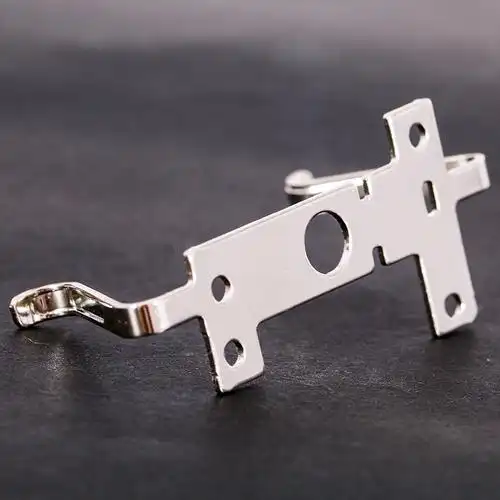
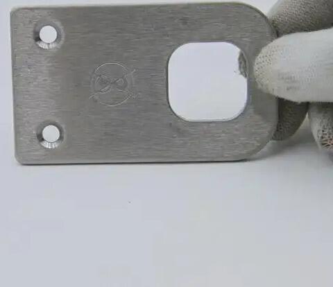
ตามแนวทางการผลิตโลหะแผ่นที่ได้รับการรับรองจาก Approved Sheet Metal ตัวยึดทำหน้าที่เป็นชิ้นส่วนกลางที่ใช้ยึดวัตถุต่างๆ เข้าด้วยกัน จัดแนวชิ้นส่วนภายในโครงหุ้ม หรือเสริมความแข็งแรงของโครงสร้าง ในแอปพลิเคชันยานยนต์ หน้าที่เหล่านี้มีความสำคัญอย่างยิ่งต่อความปลอดภัยและสมรรถนะของยานพาหนะ
ข้อกำหนดด้านความแม่นยำที่สำคัญสำหรับการผลิตชิ้นส่วนเหล็กในอุตสาหกรรมยานยนต์ ได้แก่:
- ความคลาดเคลื่อนของมิติที่แคบมาก: ความคลาดเคลื่อน ±0.005 นิ้ว ถึง ±0.010 นิ้ว สำหรับลักษณะการยึดที่สำคัญ เพื่อให้มั่นใจว่าการจัดแนวจะถูกต้องระหว่างการประกอบด้วยหุ่นยนต์ความเร็วสูง
- การจัดวางรูอย่างสม่ำเสมอ: รูสำหรับยึดต้องจัดแนวให้ตรงกันอย่างสมบูรณ์แบบระหว่างชิ้นส่วนที่ต้องประกอบเข้าด้วยกัน — แม้ความเบี่ยงเบนเล็กน้อยก็อาจก่อให้เกิดความล่าช้าในการประกอบ
- ความแม่นยำเชิงมุม: โครงยึดที่โค้งงอและชิ้นส่วนโครงสร้างต้องมีความแม่นยำ ±0.5° หรือดีกว่านั้น เพื่อรักษาเส้นทางการรับแรงให้เหมาะสม
- การย้อนกลับต้นทางของวัสดุ: ใบรับรองวัสดุที่จัดทำเป็นเอกสารจะติดตามแหล่งที่มาของชิ้นส่วนตั้งแต่วัตถุดิบจนถึงชิ้นส่วนสำเร็จรูป
การเลือกวัสดุสำหรับการใช้งานในยานยนต์ต้องคำนึงถึงสมดุลระหว่างความแข็งแรง น้ำหนัก และความต้านทานการกัดกร่อน เหล็กกล้าผสมต่ำความแข็งแรงสูง (HSLA) ใช้รับแรงโครงสร้าง ในขณะที่การขึ้นรูปอลูมิเนียมช่วยลดน้ำหนักในแอปพลิเคชันที่ไม่ใช่โครงสร้าง ส่วนเหล็กกล้าไร้สนิมใช้ในชิ้นส่วนระบบไอเสียและบริเวณที่สัมผัสกับสารเคมีบนถนน
ตู้ครอบอุปกรณ์อิเล็กทรอนิกส์และชิ้นส่วนแชสซี
การใช้งานอุปกรณ์อิเล็กทรอนิกส์มีความต้องการด้านความแม่นยำที่แตกต่างโดยสิ้นเชิง ซึ่งประเด็นหลักจะเปลี่ยนไปเป็นประสิทธิภาพของการป้องกันการรบกวนแม่เหล็กไฟฟ้า (EMI) การจัดการความร้อน และคุณภาพด้านรูปลักษณ์สำหรับผลิตภัณฑ์ที่ลูกค้ามองเห็น
การป้องกันคลื่นแม่เหล็กไฟฟ้า (EMI) ต้องอาศัยเส้นทางนำไฟฟ้าที่ต่อเนื่องรอบรอยต่อและช่องเปิดของเปลือกหุ้ม ช่องว่างใดๆ ในการป้องกัน—แม้แต่ช่องว่างเล็กๆ ที่เกิดจากความแปรผันของมิติ—อาจก่อให้เกิดการรั่วไหลของคลื่นความถี่วิทยุ ซึ่งนำไปสู่ความล้มเหลวในการผ่านข้อกำหนดด้านกฎระเบียบ สิ่งนี้หมายความว่า ข้อกำหนดด้านความแม่นยำจะเน้นหนักเป็นพิเศษที่ความเรียบ ความตรงของขอบ และความสม่ำเสมอของช่องว่างระหว่างรอยต่อ มากกว่าเพียงแค่ตำแหน่งของรูเจาะ
การจัดการความร้อนเพิ่มความซับซ้อนอีกชั้นหนึ่ง แผ่นกระจายความร้อน (heat sinks), แผงระบายอากาศ และส่วนประกอบของโครงแชสซี จำเป็นต้องติดตั้งให้แนบสนิทกับอุปกรณ์ที่สร้างความร้อน ความโค้งงอหรือความแปรผันของมิติใดๆ จะก่อให้เกิดช่องว่างอากาศ ซึ่งลดประสิทธิภาพการถ่ายเทความร้อนลงอย่างมาก
สำหรับเปลือกหุ้มอุปกรณ์อิเล็กทรอนิกส์ การขึ้นรูปอลูมิเนียมเป็นที่นิยมใช้มากที่สุด เนื่องจากมีคุณสมบัติการนำความร้อนได้ดีเยี่ยม มีคุณสมบัติในการป้องกันคลื่นแม่เหล็กไฟฟ้า (EMI) ตามธรรมชาติ และมีน้ำหนักเบา ร้านขึ้นรูปโลหะที่มีทักษะสูงจะเข้าใจข้อกำหนดเฉพาะสำหรับการใช้งานเหล่านี้ และออกแบบให้สอดคล้องกับข้อกำหนดดังกล่าว
ข้อกำหนดด้านความแม่นยำโดยทั่วไปสำหรับการใช้งานอุปกรณ์อิเล็กทรอนิกส์:
- ความเรียบของผิวพื้น: สำคัญต่อพื้นที่เชื่อมต่อทางความร้อน—มักกำหนดไว้ที่ 0.002 นิ้วต่อนิ้ว หรือแม่นยำยิ่งกว่านั้น
- ความตรงของขอบ: รับประกันการบีบอัดของซีลกันคลื่นแม่เหล็กไฟฟ้า (EMI gasket) อย่างเหมาะสม และประสิทธิภาพในการปิดผนึก
- คุณภาพผิวเรียบสวยงาม: ผลิตภัณฑ์อิเล็กทรอนิกส์สำหรับผู้บริโภคต้องการพื้นผิวที่ไม่มีรอยขีดข่วน ซึ่งเหมาะสำหรับการพ่นสีหรือการชุบออกไซด์ (anodizing)
- ขนาดของช่องเปิดที่ตัดอย่างแม่นยำ: หน้าต่างแสดงผล ช่องเปิดสำหรับขั้วต่อ และลวดลายช่องระบายอากาศ ต้องมีขอบที่เรียบเนียน
ต่างจากแอปพลิเคชันยานยนต์ที่ชิ้นส่วนมักถูกฝังอยู่ภายในชุดประกอบ อุปกรณ์อิเล็กทรอนิกส์มักยังคงมองเห็นได้โดยผู้ใช้ปลายทาง ส่งผลให้คุณภาพพื้นผิวและลักษณะภายนอกมีความสำคัญเทียบเท่ากับความแม่นยำของมิติ—จึงส่งผลต่อลำดับความสำคัญของการตรวจสอบและข้อกำหนดด้านการตกแต่งที่แตกต่างออกไป
ชิ้นส่วนอุปกรณ์และเครื่องจักรอุตสาหกรรม
ข้อกำหนดด้านการผลิตอุตสาหกรรมมีความหลากหลายอย่างมากตามการใช้งานเฉพาะ แต่โดยทั่วไปจะให้ความสำคัญกับความทนทาน ความแข็งแรงเชิงโครงสร้าง และอายุการใช้งานยาวนาน มากกว่าความแม่นยำในมิติที่สูงมากซึ่งจำเป็นในภาคยานยนต์หรืออิเล็กทรอนิกส์
อุปกรณ์ป้องกันเครื่องจักร โครงสร้างหลัก และฝาครอบอุปกรณ์มักสามารถรองรับข้อกำหนดด้านมิติที่คล่องตัวมากขึ้น—เช่น ความคลาดเคลื่อน ±0.030 นิ้ว หรือมากกว่านั้น สำหรับลักษณะที่ไม่สำคัญต่อการใช้งาน อย่างไรก็ตาม พื้นผิวสำหรับการยึดติด ผิวที่รองรับแบริ่ง และลักษณะที่ต้องการความแม่นยำในการจัดแนวยังคงต้องได้รับการควบคุมอย่างเข้มงวด
การผลิตชิ้นส่วนตามแบบเฉพาะสำหรับงานอุตสาหกรรมมักใช้วัสดุที่มีความหนา (gauge) มากกว่าและมีขนาดชิ้นส่วนใหญ่กว่าการผลิตชิ้นส่วนสำหรับยานยนต์หรืออุปกรณ์อิเล็กทรอนิกส์ ผู้ผลิตชิ้นส่วนโลหะแผ่นที่ดำเนินงานในสาขาเหล่านี้จึงจำเป็นต้องมีอุปกรณ์ที่มีความสามารถสอดคล้องกับความต้องการดังกล่าว เช่น เครื่องดัดโลหะแบบแรงดันสูงที่มีขนาดใหญ่ขึ้น เครื่องตัดด้วยเลเซอร์ที่มีโต๊ะทำงานยาวขึ้น และระบบขนย้ายวัสดุแบบหนักพิเศษ
แอปพลิเคชันของอุปกรณ์อุตสาหกรรม ได้แก่:
- อุปกรณ์ป้องกันเครื่องจักรและเปลือกครอบเพื่อความปลอดภัย: ความคลาดเคลื่อนด้านมิติในระดับปานกลาง แต่มีการสร้างที่แข็งแรงทนทานเพื่อการคุ้มครองผู้ปฏิบัติงาน
- ตู้ควบคุมแผงควบคุม: การป้องกันการรั่วซึมจากสภาพอากาศและการรบกวนแม่เหล็กไฟฟ้า (EMI) สำหรับการใช้งานกลางแจ้งหรือในสภาพแวดล้อมที่มีสัญญาณรบกวนทางไฟฟ้าสูง
- ส่วนประกอบโครงสร้าง: โครงสร้างรับน้ำหนักและตัวรองรับที่ต้องมีใบรับรองวัสดุและเอกสารรับรองคุณภาพของการเชื่อม
- ป้ายโลหะแบบกำหนดเอง: ป้ายบอกทิศทาง ป้ายความปลอดภัย และป้ายระบุตัวตน ซึ่งต้องมีความทนทานของพื้นผิวตามข้อกำหนดเฉพาะ
| อุตสาหกรรม | ระยะความอดทนทั่วไป | วัสดุหลัก | ข้อกำหนดหลักด้านพื้นผิว | ปัจจัยด้านคุณภาพที่สำคัญ |
|---|---|---|---|---|
| รถยนต์ | ±0.005" ถึง ±0.015" | เหล็กกล้าความแข็งแรงสูงผสมโลหะ (HSLA), อลูมิเนียม, สแตนเลส | การเคลือบด้วยไฟฟ้า (E-coat), การพ่นผงเคลือบ (powder coat), การชุบสังกะสี (zinc plating) | ความเหมาะสมในการประกอบ (Assembly fit), ความต้านทานต่อการเหนื่อยล้า (fatigue resistance), ความสามารถในการติดตามที่มา (traceability) |
| อิเล็กทรอนิกส์ | ±0.010" ถึง ±0.020" | อลูมิเนียม, เหล็กแผ่นรีดเย็น (cold-rolled steel), ทองแดง | การออกซิไดซ์ (Anodizing), การชุบโครเมต (chromate), การชุบนิกเกิล (nickel plating) | การป้องกันการรบกวนแม่เหล็กไฟฟ้า (EMI shielding), การสัมผัสทางความร้อน (thermal contact), คุณลักษณะด้านรูปลักษณ์ (cosmetics) |
| อุตสาหกรรม | ±0.020 นิ้ว ถึง ±0.060 นิ้ว | เหล็กกล้าคาร์บอนต่ำ (mild steel), สแตนเลส, อลูมิเนียม | การพ่นผงเคลือบ (powder coat), การชุบสังกะสีแบบจุ่มร้อน (galvanizing), การทาสี (paint) | ความทนทาน (Durability), ความสมบูรณ์ของโครงสร้าง (structural integrity), ความต้านทานต่อการกัดกร่อน (corrosion resistance) |
ข้อพิจารณาเกี่ยวกับต้นแบบเทียบกับการผลิต แตกต่างกันอย่างมากในอุตสาหกรรมเหล่านี้ ในระหว่างขั้นตอนการพัฒนา จุดเน้นจะเปลี่ยนไปสู่การตรวจสอบความถูกต้องของการออกแบบ (design validation), การตรวจสอบความพอดี (fit checking), และการทดสอบการทำงาน (functional testing) การผลิตต้นแบบ (Prototype runs) มักประกอบด้วย:
- ปริมาณที่น้อยกว่า แต่มีความต้องการให้ส่งมอบเร็วขึ้น
- ยอมรับข้อบกพร่องด้านรูปลักษณ์เล็กน้อยได้มากขึ้น
- มีความยืดหยุ่นในการปรับปรุงแบบตามผลการทดสอบ
- ให้ความสำคัญกับการลดต้นทุนต่อชิ้นน้อยลง
การผลิตในเชิงพาณิชย์จะกลับลำดับความสำคัญเหล่านี้ โดยการผลิตจำนวนมากต้องการคุณภาพที่สม่ำเสมอสำหรับชิ้นส่วนหลายพันชิ้น กระบวนการที่ถูกปรับให้เหมาะสมเพื่อประสิทธิภาพด้านต้นทุน ขั้นตอนการทำงานที่จัดทำเอกสารไว้เพื่อให้สอดคล้องกับข้อกำหนดด้านกฎระเบียบ และการควบคุมกระบวนการเชิงสถิติ (Statistical Process Control) เพื่อรักษาความแม่นยำของขนาดภายในขอบเขตที่กำหนดตลอดระยะเวลาการผลิตที่ยาวนาน
การเข้าใจว่าโครงการของคุณอยู่ที่ตำแหน่งใดบนสเปกตรัมนี้ — และการสื่อสารความต้องการเหล่านั้นอย่างชัดเจนไปยังผู้ให้บริการงานขึ้นรูปของคุณ — จะช่วยให้มั่นใจได้ว่าคุณจะได้รับความใส่ใจอย่างเหมาะสมต่อปัจจัยที่แท้จริงแล้วมีความสำคัญต่อการใช้งานเฉพาะของคุณ หลังจากที่ความต้องการของอุตสาหกรรมได้รับการชี้แจงอย่างชัดเจนแล้ว คุณก็พร้อมที่จะเดินผ่านวงจรชีวิตของโครงการทั้งหมด ตั้งแต่การส่งแบบดีไซน์เริ่มต้น จนถึงการส่งมอบชิ้นส่วนที่ผลิตเสร็จสมบูรณ์
วัฏจักรชีวิตของโครงการแบบครบวงจร
คุณเข้าใจวัสดุ กระบวนการ ความคลาดเคลื่อนที่ยอมรับได้ (tolerances) และมาตรฐานคุณภาพ แต่โครงการจริงๆ นั้นจะดำเนินไปอย่างไร ตั้งแต่แนวคิดเริ่มต้นของคุณจนถึงชิ้นส่วนสำเร็จรูปมาถึงท่าเรือของคุณ? การเข้าใจวงจรชีวิตของโครงการโดยสมบูรณ์จะช่วยให้คุณวางแผนกำหนดเวลาได้อย่างมีประสิทธิภาพ หลีกเลี่ยงจุดติดขัด และทำงานร่วมกับพันธมิตรด้านการผลิตของคุณได้อย่างมีประสิทธิผลมากยิ่งขึ้น
ทุกโครงการผลิตชิ้นส่วนโลหะแผ่นแบบแม่นยำจะผ่านลำดับขั้นตอนที่คาดการณ์ได้—แม้ว่ารายละเอียดปลีกย่อยอาจแตกต่างกันไปตามระดับความซับซ้อน ปริมาณการผลิต และความเร่งด่วน ความเข้าใจในสิ่งที่เกิดขึ้นในแต่ละขั้นตอนจะช่วยให้คุณเตรียมข้อมูลที่เหมาะสมล่วงหน้า และคาดการณ์ล่วงหน้าได้ว่าอาจเกิดความล่าช้าที่จุดใดบ้าง
จากไฟล์ออกแบบสู่ชิ้นงานสำเร็จรูป
ให้คุณมองกระบวนการผลิตชิ้นส่วนโลหะแผ่นเป็นเหมือนชุดประตู (gates) ที่ต้องผ่านทีละบาน แต่ละขั้นตอนจะต้องเสร็จสมบูรณ์อย่างประสบความสำเร็จก่อนที่ขั้นตอนถัดไปจะเริ่มต้นขึ้น การเร่งรัดหรือข้ามขั้นตอนแรกๆ ไปโดยเด็ดขาด จะก่อให้เกิดปัญหาที่ทวีความรุนแรงขึ้นเรื่อยๆ ตลอดกระบวนการผลิต
นี่คือลำดับขั้นตอนทั่วไปของโครงการผลิตชิ้นส่วนโลหะแผ่นแบบแม่นยำ:
- การส่งแบบออกแบบ: คุณจัดเตรียมไฟล์ CAD แบบร่าง และข้อกำหนดต่างๆ ซึ่งเอกสารฉบับสมบูรณ์ในขั้นตอนนี้จะช่วยป้องกันความล่าช้าในภายหลัง โปรดระบุความต้องการวัสดุ ค่าความคลาดเคลื่อนที่ยอมรับได้ (tolerance) ข้อกำหนดด้านพื้นผิว (finish) และปริมาณที่ต้องการ
- DFM Review: การตรวจสอบการทํางาน ผู้ผลิตชิ้นส่วนจะวิเคราะห์การออกแบบของคุณเพื่อประเมินความเหมาะสมในการผลิต (DFM) ซึ่งเป็นขั้นตอนสำคัญที่ช่วยระบุปัญหาที่อาจเกิดขึ้นล่วงหน้า เช่น รัศมีการโค้งที่แคบเกินไป การจัดตำแหน่งรูที่ไม่เหมาะสม หรือลักษณะเฉพาะที่ต้องใช้อุปกรณ์พิเศษ — ก่อนที่ปัญหาเหล่านี้จะกลายเป็นอุปสรรคในการผลิตจริง
- การเสนอราคา: จากผลการทบทวน DFM คุณจะได้รับใบเสนอราคาสำหรับชิ้นต้น (prototype) และชิ้นงานสำหรับการผลิตจริง โดยใบเสนอราคาสำหรับชิ้นส่วนโลหะแผ่น (sheet metal) จะแยกค่าใช้จ่ายอย่างละเอียด ได้แก่ ค่าวัสดุ ค่าการแปรรูป ค่าการตกแต่งพื้นผิว (finishing) และค่าการตรวจสอบ เพื่อให้คุณเข้าใจปัจจัยที่มีผลต่อราคา
- การสร้างตัวอย่างทดลอง: จะมีการผลิตตัวอย่างเบื้องต้นเพื่อยืนยันการออกแบบ (design validation) ซึ่งขั้นตอนนี้ยืนยันว่าการออกแบบของคุณทำงานตามวัตถุประสงค์ที่ตั้งไว้ และกระบวนการผลิตของผู้ผลิตสามารถสร้างชิ้นส่วนที่สอดคล้องกับข้อกำหนดได้
- การรับรอง: คุณตรวจสอบชิ้นส่วนต้นแบบเทียบกับข้อกำหนดที่กำหนดไว้ รายงานการตรวจสอบชิ้นงานแรกจะบันทึกความสอดคล้องด้านมิติ ขั้นตอนนี้รับประกันว่าการผลิตจะไม่เริ่มขึ้นจนกว่าคุณภาพจะเป็นไปตามข้อกำหนด
- ผลิต: การผลิตในปริมาณเต็มรูปแบบจะเริ่มขึ้นโดยใช้กระบวนการและเครื่องมือที่ได้รับการอนุมัติแล้ว การควบคุมกระบวนการเชิงสถิติ (Statistical Process Control) จะติดตามความสม่ำเสมอตลอดระยะเวลาการผลิต
- การตรวจสอบ: การยืนยันขั้นสุดท้ายจะยืนยันว่าชิ้นส่วนสอดคล้องกับข้อกำหนดก่อนจัดส่ง ชุดเอกสารประกอบจะรวมถึงรายงานการตรวจสอบ ใบรับรองวัสดุ และเอกสารการปฏิบัติตามข้อกำหนดอื่นๆ ที่จำเป็น
- การจัดส่ง: ชิ้นส่วนสำเร็จรูปจะถูกจัดส่งพร้อมบรรจุภัณฑ์ที่เหมาะสมเพื่อป้องกันความเสียหาย การประสานงานด้านโลจิสติกส์จะรับประกันว่าชิ้นส่วนจะมาถึงในเวลาที่สายการประกอบของคุณต้องการ
ความเร็วในการดำเนินผ่านขั้นตอนเหล่านี้ขึ้นอยู่กับศักยภาพของพาร์ทเนอร์ด้านการผลิตของคุณเป็นอย่างมาก ตามผลการวิจัยอุตสาหกรรมเกี่ยวกับกลยุทธ์การสร้างต้นแบบ การผลิตชิ้นส่วนโลหะแผ่นแบบเร่งด่วนสามารถลดระยะเวลาการพัฒนาลงได้อย่างมาก โดยเฉพาะในระยะการสร้างต้นแบบซึ่งเป็นระยะสำคัญที่มีการปรับปรุงแบบออกแบบอย่างรวดเร็ว
ผู้ผลิตบางรายให้บริการสร้างต้นแบบชิ้นส่วนโลหะแผ่น โดยสามารถส่งมอบภายใน 5 วัน ทำให้สามารถปรับปรุงแบบออกแบบได้หลายรอบภายในเวลาเพียงไม่กี่สัปดาห์ แทนที่จะใช้เวลาเป็นเดือน Shaoyi (Ningbo) Metal Technology , การสนับสนุนการออกแบบเพื่อการผลิต (DFM) อย่างครอบคลุมร่วมกับการเสนอราคาภายใน 12 ชั่วโมง ช่วยเร่งกระบวนการขั้นต้นของวงจรชีวิตโครงการโดยรวม — ทำให้คุณสามารถย้ายจากแนวคิดไปสู่ต้นแบบได้รวดเร็วยิ่งขึ้น
การเปลี่ยนผ่านจากต้นแบบชิ้นส่วนโลหะแผ่นสู่การผลิตจริง
การเปลี่ยนผ่านจากชิ้นส่วนโลหะแผ่นต้นแบบสู่การผลิตเต็มรูปแบบนั้นไม่ใช่เพียงแค่การผลิตชิ้นส่วนในปริมาณมากขึ้นเท่านั้น แต่ยังเป็นการเปลี่ยนแปลงพื้นฐานในด้านลำดับความสำคัญ กระบวนการ และความคาดหวังอีกด้วย
ในระยะการสร้างต้นแบบ ความยืดหยุ่นคือหลักการสำคัญ คุณอาจยอมรับความแปรผันเล็กน้อยในด้านลักษณะภายนอก ยอมรับระยะเวลาในการผลิตต่อชิ้นที่ยาวนานขึ้น และให้ความสำคัญกับความเร็วเหนือการปรับปรุงประสิทธิภาพด้านต้นทุน เป้าหมายคือการตรวจสอบและยืนยันการออกแบบ — เพื่อพิสูจน์ว่าแนวคิดของคุณสามารถทำงานได้จริง ก่อนที่จะลงทุนในแม่พิมพ์และกระบวนการผลิตสำหรับการผลิตจริง
แต่เมื่อเข้าสู่ขั้นตอนการผลิตจริง ลำดับความสำคัญเหล่านี้จะกลับกัน:
- ความสม่ำเสมอกลายเป็นสิ่งสำคัญที่สุด: ชิ้นส่วนทุกชิ้นต้องตรงตามตัวอย่างแรกที่ได้รับการอนุมัติ ทุกครั้งที่ผลิต
- ประสิทธิภาพด้านต้นทุนมีความสำคัญ: การปรับปรุงกระบวนการ การเพิ่มอัตราการใช้วัสดุให้เกิดประโยชน์สูงสุด และการลดระยะเวลาในการผลิตแต่ละรอบ ส่งผลโดยตรงต่อผลกำไรสุทธิของคุณ
- เอกสารเพิ่มขึ้น: ความต้องการด้านการติดตามย้อนกลับ ข้อมูลการควบคุมกระบวนการเชิงสถิติ (SPC) และเอกสารการปฏิบัติตามข้อกำหนดเพิ่มขึ้นอย่างมีนัยสำคัญ
- การลงทุนในแม่พิมพ์อาจได้รับการพิจารณาอย่างสมเหตุสมผล: ปริมาณการผลิตสูงสามารถรองรับการลงทุนในแม่พิมพ์เฉพาะ การจัดวางชิ้นงาน (fixtures) หรือระบบจัดการอัตโนมัติ ซึ่งจะช่วยลดต้นทุนต่อชิ้นงาน
ความสามารถในการขึ้นรูปโลหะแผ่นแบบเร่งด่วน (Quick turn sheet metal fabrication) มีความสำคัญแตกต่างกันไปในแต่ละระยะ: สำหรับต้นแบบ (prototypes) ความเร็วช่วยให้สามารถปรับปรุงและทดสอบซ้ำได้อย่างรวดเร็ว; สำหรับการผลิตจริง ความเร็วนี้หมายถึงศักยภาพในการตอบสนองอย่างทันท่วงทีเมื่อความต้องการเพิ่มขึ้นอย่างฉับพลัน หรือเมื่อมีการเปลี่ยนแปลงกำหนดเวลา
การเปลี่ยนผ่านนั้นเองต้องอาศัยการวางแผนอย่างรอบคอบ ผู้ผลิตชิ้นส่วนโลหะแผ่นของท่านควรทบทวนผลลัพธ์จากต้นแบบ ระบุขั้นตอนที่จำเป็นต้องปรับปรุงเพื่อการผลิตในปริมาณมาก และยืนยันว่าระบบควบคุมคุณภาพพร้อมใช้งานแล้วเพื่อรักษาความสม่ำเสมอของคุณภาพเมื่อผลิตในปริมาณที่เพิ่มขึ้น นี่คือจุดที่ผู้ผลิตชิ้นส่วนโลหะแผ่นที่มีประสบการณ์สูงสามารถเพิ่มมูลค่าให้โครงการได้อย่างมาก — เนื่องด้วยพวกเขาเคยดำเนินการเปลี่ยนผ่านนี้มาแล้วหลายพันครั้ง จึงรู้ดีว่าปัญหามักเกิดขึ้นที่จุดใด
การทำงานร่วมกับผู้ผลิตชิ้นส่วนโลหะแผ่นของท่านอย่างมีประสิทธิภาพ
ความสัมพันธ์ระหว่างท่านกับผู้ผลิตชิ้นส่วนโลหะแผ่นมีผลกระทบโดยตรงต่อความสำเร็จของโครงการ การปฏิบัติต่อผู้ผลิตเหล่านั้นในฐานะ 'พันธมิตรที่แท้จริง' แทนที่จะมองเป็นเพียง 'ผู้ขายที่รับทำตามคำสั่ง' จะช่วยเปิดโอกาสให้ท่านเข้าถึงศักยภาพและบริการที่ท่านอาจไม่เคยทราบมาก่อน
ความร่วมมือที่มีประสิทธิภาพนั้นมีลักษณะอย่างไรในทางปฏิบัติ
มีส่วนร่วมตั้งแต่ระยะเริ่มต้นของกระบวนการออกแบบ ตาม แนวทางปฏิบัติที่ดีที่สุดสำหรับการสร้างต้นแบบชิ้นส่วนโลหะแผ่น การนำความเชี่ยวชาญด้านการผลิตเข้ามาเกี่ยวข้องตั้งแต่ขั้นตอนการออกแบบจะช่วยระบุปัญหาที่เกี่ยวข้องกับความสามารถในการผลิตได้ก่อนที่ปัญหาเหล่านั้นจะถูกผสานเข้าไปอย่างถาวรในไฟล์ CAD ของคุณ ผู้ผลิตจำนวนมากเสนอการทบทวน DFM (Design for Manufacturability) เป็นส่วนหนึ่งของกระบวนการเสนอราคา — โปรดใช้ประโยชน์จากความเชี่ยวชาญนี้
สื่อสารความต้องการอย่างชัดเจน ผู้ผลิตของคุณไม่สามารถอ่านใจคุณได้ โปรดระบุอย่างชัดเจนว่าค่าความคลาดเคลื่อนใดมีความสำคัญเป็นพิเศษ และค่าใดเป็นเพียงค่าที่ต้องการเท่านั้น อธิบายว่าชิ้นส่วนจะถูกนำไปใช้งานอย่างไร เพื่อให้ผู้ผลิตสามารถแนะนำวัสดุและพื้นผิวที่เหมาะสมได้ แจ้งข้อจำกัดด้านระยะเวลาของคุณให้ผู้ผลิตทราบ เพื่อให้พวกเขาสามารถวางแผนกำลังการผลิตได้อย่างเหมาะสม
จัดเตรียมเอกสารให้ครบถ้วน ข้อมูลที่ขาดหายจะก่อให้เกิดความล่าช้า โปรดรวมข้อกำหนดที่เกี่ยวข้องทั้งหมด รายการอุปกรณ์ที่ใช้ ข้อกำหนดด้านพื้นผิว และการประมาณจำนวนชิ้นส่วนไว้ในเอกสารที่ส่งครั้งแรกของคุณ ยิ่งเอกสารของคุณครบถ้วนมากเท่าไร ราคาเสนอของคุณก็จะได้รับการจัดทำได้เร็วและแม่นยำมากขึ้นเท่านั้น
ตอบกลับอย่างรวดเร็วระหว่างกระบวนการ จะมีคำถามเกิดขึ้น—เกี่ยวกับเจตนาในการออกแบบ ทางเลือกที่ยอมรับได้ หรือการอนุมัติตัวอย่าง คำตอบที่รวดเร็วจะช่วยให้โครงการดำเนินไปอย่างต่อเนื่อง การตอบคำถามล่าช้าจะส่งผลให้การจัดส่งล่าช้าตามไปด้วย
ประเมินคู่ค้าโดยพิจารณาจากปัจจัยอื่นนอกเหนือจากราคา ใบรับรอง ศักยภาพของอุปกรณ์ การสนับสนุนการออกแบบเพื่อการผลิต (DFM) เวลาดำเนินการ และเอกสารรับรองคุณภาพ ล้วนมีความสำคัญ ผู้ผลิตชิ้นส่วนที่สามารถตรวจพบปัญหาในการออกแบบระหว่างขั้นตอนการทบทวน จะช่วยประหยัดค่าใช้จ่ายให้คุณได้มากกว่าความแตกต่างของราคาเสนอระหว่างข้อเสนอที่ต่ำที่สุดกับข้อเสนอที่ต่ำเป็นอันดับสอง
ความสามารถในการสร้างต้นแบบอย่างรวดเร็ว—เช่น ระยะเวลาดำเนินการภายใน 5 วัน ซึ่งผู้ผลิตชิ้นส่วนที่มีคุณสมบัติเหมาะสมสามารถให้บริการได้—จะช่วยเร่งวงจรการพัฒนาอย่างมีนัยสำคัญ อย่างไรก็ตาม ความเร็วโดยไม่มีคุณภาพจะก่อให้เกิดปัญหา ดังนั้นควรเลือกคู่ค้าที่สามารถมอบทั้งสองสิ่งนี้ได้ คือ ความรวดเร็วในการส่งมอบควบคู่ไปกับระบบประกันคุณภาพที่แข็งแกร่งและกระบวนการที่มีการบันทึกไว้อย่างชัดเจน
ด้วยความเข้าใจที่ชัดเจนเกี่ยวกับวงจรชีวิตของโครงการและวิธีการทำงานร่วมกับพันธมิตรผู้ผลิตอย่างมีประสิทธิภาพ คุณจึงพร้อมที่จะตัดสินใจอย่างมีข้อมูลสำหรับโครงการงานโลหะแผ่นความแม่นยำของคุณ แล้วขั้นตอนสุดท้ายคืออะไร? คือการรวมองค์ความรู้ทั้งหมดที่คุณได้เรียนรู้มาให้กลายเป็นเกณฑ์เชิงปฏิบัติ เพื่อก้าวหน้าต่อไปด้วยความมั่นใจ
การตัดสินใจอย่างมีข้อมูลสำหรับโครงการความแม่นยำของคุณ
คุณได้ศึกษาผ่านหัวข้อต่าง ๆ ทั้งวัสดุ กระบวนการ ค่าความคลาดเคลื่อน (tolerances) ระบบควบคุมคุณภาพ และการประยุกต์ใช้งานในอุตสาหกรรมมาแล้ว ถึงเวลาที่สำคัญที่สุดแล้ว: นำความรู้เหล่านี้ไปปฏิบัติจริง ไม่ว่าคุณจะกำลังจัดหาชิ้นส่วนโลหะแผ่นความแม่นยำแบบกำหนดเองครั้งแรก หรือกำลังปรับปรุงห่วงโซ่อุปทานที่มีอยู่ การตัดสินใจที่คุณจะทำต่อจากนี้จะเป็นตัวกำหนดว่าชิ้นส่วนของคุณจะส่งถึงตามกำหนดเวลา ตรงตามข้อกำหนดทางเทคนิค (within spec) และพร้อมสำหรับการประกอบหรือไม่
ความสำเร็จในการผลิตชิ้นส่วนความแม่นยำไม่ได้เกิดขึ้นโดยบังเอิญ แต่เกิดจากการผสมผสานอย่างลงตัวระหว่างการออกแบบที่ชาญฉลาด การเลือกวัสดุที่เหมาะสม กระบวนการผลิตที่มีศักยภาพ และพันธมิตรที่มีคุณสมบัติเหมาะสม ซึ่งทั้งหมดนี้ร่วมมือกันเพื่อให้บรรลุตามข้อกำหนดเฉพาะของคุณ
ปัจจัยสำคัญที่ควรพิจารณาก่อนเริ่มโครงการของคุณ
ก่อนส่งคำขอเสนอราคา (RFQ) ฉบับแรก โปรดหยุดพิจารณาและตรวจสอบให้แน่ใจว่าคุณได้ดำเนินการแก้ไขประเด็นพื้นฐานที่ส่งผลต่อความสำเร็จของโครงการแล้ว
ปัจจัยสำคัญที่สุดที่ส่งผลต่อความสำเร็จของโครงการงานโลหะแผ่นความแม่นยำ ได้แก่ การนำหลักการออกแบบเพื่อการผลิต (DFM) ไปประยุกต์ใช้ตั้งแต่ระยะเริ่มต้นของการออกแบบ การเลือกวัสดุที่สอดคล้องกับข้อกำหนดด้านประสิทธิภาพของคุณ การระบุค่าความคลาดเคลื่อน (tolerances) ที่เหมาะสมกับการใช้งานจริงของคุณ แทนที่จะใช้ค่าที่รัดกุมเกินความจำเป็นโดยอัตโนมัติ และการร่วมมือกับผู้รับจ้างผลิตชิ้นส่วนที่มีใบรับรองและศักยภาพสอดคล้องกับมาตรฐานคุณภาพที่คุณกำหนด
ปัจจัยเหล่านี้ไม่ทำงานอย่างแยกจากกัน แต่กลับเชื่อมโยงกันเป็นระบบแบบบูรณาการ ตัวอย่างเช่น การเลือกวัสดุของคุณส่งผลต่อค่าความคลาดเคลื่อนที่สามารถบรรลุได้ ข้อกำหนดด้านค่าความคลาดเคลื่อนของคุณมีอิทธิพลต่อการเลือกวิธีการผลิต ข้อกำหนดด้านกระบวนการผลิตของคุณกำหนดว่าผู้รับจ้างผลิตรายใดสามารถส่งมอบงานได้จริง และการตัดสินใจด้านการออกแบบของคุณส่งผลกระทบต่อทุกขั้นตอนที่ตามมา
โปรดตั้งคำถามเหล่านี้กับตนเองก่อนดำเนินการต่อ:
- คุณได้ระบุแล้วหรือไม่ว่ามิติใดบ้างที่มีความสำคัญอย่างยิ่งจริง ๆ กับมิติใดบ้างที่เป็นเพียงสิ่งที่น่ามีแต่ไม่จำเป็น?
- การออกแบบของคุณสอดคล้องกับหลักการ DFM หรือไม่ — เช่น มีรัศมีโค้งที่เหมาะสม ระยะห่างระหว่างรูถึงขอบที่ถูกต้อง และมีการเว้นร่อง (relief cuts) ตามที่จำเป็นหรือไม่?
- คุณได้เลือกวัสดุที่สามารถสมดุลระหว่างข้อกำหนดด้านประสิทธิภาพ ความสามารถในการขึ้นรูป และต้นทุนหรือไม่?
- ข้อกำหนดด้านความคลาดเคลื่อน (tolerance) ของคุณสอดคล้องกับสิ่งที่การใช้งานจริงของคุณต้องการหรือไม่?
การประเมินผู้ให้บริการงานขึ้นรูปความแม่นยำ
การค้นหาผู้ให้บริการงานขึ้นรูปที่เหมาะสมนั้นต้องพิจารณาเกินกว่าราคาเสนอที่ต่ำที่สุดเท่านั้น ตาม เกณฑ์การคัดเลือกของ MarcTech Manufacturing บริษัทผู้ให้บริการงานขึ้นรูปแผ่นโลหะชั้นยอดจะต้องมีทั้งทักษะ เครื่องจักร และความใส่ใจในรายละเอียด เพื่อเปลี่ยนวิสัยทัศน์ของคุณให้เป็นจริง — ในขณะที่ผู้ให้บริการที่มีคุณภาพต่ำอาจนำไปสู่ความล่าช้าที่มีค่าใช้จ่ายสูง ปัญหาด้านคุณภาพ และอันตรายต่อความปลอดภัยที่อาจเกิดขึ้น
เมื่อคุณกำลังค้นหาผู้ให้บริการงานขึ้นรูปแผ่นโลหะใกล้คุณ หรือประเมินผู้ให้บริการงานขึ้นรูปโลหะใกล้คุณ โปรดพิจารณาเกณฑ์การประเมินเหล่านี้:
- ใบรับรอง: มาตรฐาน ISO 9001 รับรองกระบวนการด้านคุณภาพที่มีระบบ ขณะที่มาตรฐาน IATF 16949 แสดงถึงความสามารถในการผลิตที่มีความแม่นยำระดับอุตสาหกรรมยานยนต์ โปรดเลือกระดับการรับรองให้สอดคล้องกับข้อกำหนดของงานที่คุณดำเนินการ
- ขีดความสามารถของอุปกรณ์: เครื่องจักรกลแบบ CNC สมัยใหม่ เช่น เลเซอร์ แผ่นพับไฮดรอลิก (press brakes) และระบบวัดต่างๆ ช่วยให้สามารถควบคุมความคลาดเคลื่อนได้แคบลงและมีความซ้ำซ้อนที่ดีขึ้น โปรดสอบถามรายละเอียดจำเพาะของเครื่องจักรและโปรแกรมการบำรุงรักษา
- การสนับสนุนจาก DFM: พันธมิตรที่ทบทวนการออกแบบเพื่อประเมินความเหมาะสมต่อการผลิตจะสามารถตรวจจับปัญหาได้ตั้งแต่เนิ่นๆ ซึ่งจะช่วยประหยัดเวลาและต้นทุนของคุณในขั้นตอนต่อไป
- ระยะเวลาดำเนินการ: ศักยภาพในการสร้างต้นแบบอย่างรวดเร็ว (Rapid prototyping) ช่วยเร่งวงจรการพัฒนา ส่วนระยะเวลาการผลิตควรสอดคล้องกับความต้องการด้านการวางแผนกำหนดเวลาของคุณ
- เอกสารด้านคุณภาพ: รายงานการตรวจสอบอย่างครอบคลุม ใบรับรองวัสดุ และชุดเอกสารการตรวจสอบตัวอย่างชิ้นแรก (first article inspection packages) ช่วยให้มั่นใจในความสามารถในการติดตามย้อนกลับ (traceability) ซึ่งเป็นสิ่งที่แอปพลิเคชันที่ต้องการความแม่นยำสูงต้องการ
เมื่อค้นหาบริษัทผลิตชิ้นส่วนโลหะใกล้ตัวคุณ อย่าพิจารณาเพียงแค่ระยะทางเท่านั้น ผู้รับจ้างผลิตที่ตั้งอยู่อีกสองรัฐห่างออกไป แต่มีใบรับรองและศักยภาพที่เหมาะสม มักจะส่งมอบผลงานที่ดีกว่าร้านในท้องถิ่นที่ขาดประสบการณ์ด้านความแม่นยำ อย่างไรก็ตาม ความรวดเร็วในการสื่อสารก็มีความสำคัญ—คู่ค้าที่ตอบคำถามของคุณได้ทันทีจะช่วยให้โครงการดำเนินไปอย่างต่อเนื่อง
ก้าวไปข้างหน้าด้วยความมั่นใจ
ตอนนี้คุณเข้าใจแล้วว่าอะไรคือปัจจัยที่ทำให้โครงการผลิตชิ้นส่วนโลหะแผ่นแบบแม่นยำประสบความสำเร็จ แตกต่างจากโครงการที่มีปัญหา ความรู้ที่คุณได้รับ—เกี่ยวกับวัสดุ กระบวนการ ค่าความคลาดเคลื่อนหลัก (tolerances) หลักการ DFM (Design for Manufacturability) และระบบควบคุมคุณภาพ—จะช่วยให้คุณตัดสินใจอย่างมีข้อมูล แทนที่จะหวังเพียงว่าจะได้ผลลัพธ์ที่ดีที่สุด
นี่คือแผนปฏิบัติการของคุณ:
- นำหลักการ DFM ไปใช้ตั้งแต่เนิ่นๆ: ตรวจสอบแบบแปลนของคุณเทียบกับแนวทางการผลิตที่เป็นไปได้ก่อนส่งแบบเพื่อขอใบเสนอราคา การปรับเปลี่ยนเล็กน้อยในขั้นตอนนี้จะช่วยป้องกันปัญหาที่อาจเกิดค่าใช้จ่ายสูงในภายหลัง
- ระบุค่าความคลาดเคลื่อนอย่างมีกลยุทธ์: กำหนดค่าความคลาดเคลื่อนที่แน่นมากไว้เฉพาะสำหรับฟีเจอร์ที่จำเป็นจริงๆ เท่านั้น การระบุค่าความคลาดเคลื่อนที่แน่นเกินไปโดยไม่จำเป็นจะทำให้ต้นทุนสูงขึ้นโดยไม่เพิ่มมูลค่าใดๆ
- เลือกคู่ค้าที่มีศักยภาพที่พิสูจน์ได้: ใบรับรอง รายการลงทุนด้านอุปกรณ์ และระบบคุณภาพมีความสำคัญ โปรดค้นหาโรงงานรับจ้างขึ้นรูปโลหะใกล้คุณที่สามารถแสดงหลักฐานความสามารถในการผลิตชิ้นส่วนอย่างแม่นยำได้
- ให้มีส่วนร่วมกับผู้รับจ้างขึ้นรูปโลหะในฐานะพันธมิตร: การมีส่วนร่วมตั้งแต่เนิ่นๆ การสื่อสารอย่างชัดเจน และการแก้ไขปัญหาร่วมกัน จะนำไปสู่ผลลัพธ์ที่ดีกว่าความสัมพันธ์เชิงธุรกรรมกับผู้จำหน่าย
การขึ้นรูปโลหะแผ่นแบบแม่นยำ (Precision sheet metal fabrication) คือกระบวนการเปลี่ยนวัสดุแผ่นเรียบให้กลายเป็นชิ้นส่วนที่ขับเคลื่อนระบบที่สำคัญในหลากหลายอุตสาหกรรม เมื่อคุณผสมผสานการออกแบบอย่างรอบคอบ การเลือกวัสดุที่เหมาะสม กระบวนการผลิตที่มีศักยภาพ และพันธมิตรที่มีคุณสมบัติตรงตามเกณฑ์เข้าด้วยกัน คุณจะได้ชิ้นส่วนที่ประกอบได้พอดี ทำงานได้อย่างเชื่อถือได้ และส่งมอบตรงตามกำหนดเวลาที่คุณต้องการ
เส้นทางจากวัตถุดิบไปสู่ชิ้นส่วนสำเร็จรูปตอนนี้ชัดเจนยิ่งกว่าเมื่อคุณเริ่มอ่านบทความนี้ ถึงเวลาแล้วที่จะนำความรู้เหล่านี้ไปประยุกต์ใช้กับโครงการต่อไปของคุณ
คำถามที่พบบ่อยเกี่ยวกับการขึ้นรูปโลหะแผ่นแบบแม่นยำตามสั่ง
1. การผลิตชิ้นส่วนโลหะแผ่นตามแบบมีค่าใช้จ่ายเท่าใด?
ต้นทุนการผลิตชิ้นส่วนโลหะแผ่นตามแบบมักอยู่ในช่วง 4–48 ดอลลาร์สหรัฐต่อตารางฟุต โดยค่าใช้จ่ายเฉลี่ยของโครงการอยู่ที่ประมาณ 1,581 ดอลลาร์สหรัฐ ราคาขึ้นอยู่กับปัจจัยหลายประการ ได้แก่ การเลือกวัสดุ (เหล็กกล้าไร้สนิมมีราคาสูงกว่าเหล็กคาร์บอนต่ำ), ความซับซ้อนของการดัดและการตัด, ข้อกำหนดด้านความคลาดเคลื่อน (tolerance), ความต้องการการตกแต่งผิว (finishing), และปริมาณการผลิต ความคลาดเคลื่อนที่แคบลงและวัสดุพิเศษ เช่น เหล็กกล้าไร้สนิมเกรด 316 จะทำให้ต้นทุนเพิ่มขึ้น ขณะที่การผลิตในปริมาณมากจะช่วยลดต้นทุนต่อชิ้นผ่านการปรับปรุงประสิทธิภาพกระบวนการ
2. ความคลาดเคลื่อน (tolerance) ที่สามารถบรรลุได้จากการผลิตชิ้นส่วนโลหะแผ่นแบบแม่นยำคือเท่าใด?
การตัดด้วยเลเซอร์สามารถบรรลุความคลาดเคลื่อนได้แน่นหนาถึง ±0.005 นิ้ว สำหรับมิติเชิงเส้น และ ±0.003 นิ้ว สำหรับเส้นผ่านศูนย์กลางรู การเจาะด้วยเครื่อง CNC โดยทั่วไปรักษาระดับความคลาดเคลื่อนมาตรฐานไว้ที่ ±0.010 นิ้ว และสามารถทำได้ถึง ±0.004 นิ้ว สำหรับงานที่ต้องการความแม่นยำสูง การดัดรักษาระดับความแม่นยำเชิงมุมภายใน ±0.5 องศา และความคลาดเคลื่อนเชิงมิติที่ ±0.015 นิ้ว ผู้ให้บริการผลิตชิ้นส่วนโลหะแผ่นที่ได้รับการรับรองมาตรฐาน IATF 16949 เช่น Shaoyi Metal Technology สามารถให้ความแม่นยำระดับอุตสาหกรรมยานยนต์สำหรับชิ้นส่วนโครงสร้างและแชสซี
3. ซอฟต์แวร์ใดดีที่สุดสำหรับการออกแบบชิ้นส่วนโลหะแผ่น?
ผู้เชี่ยวชาญในอุตสาหกรรมมักใช้ SolidWorks, Autodesk Inventor และ CATIA Sheet Metal Designer สำหรับการออกแบบชิ้นส่วนโลหะแผ่น แพลตฟอร์ม CAD เหล่านี้มีโมดูลเฉพาะสำหรับงานโลหะแผ่น ซึ่งสามารถคำนวณค่าการยืดหยุ่นขณะดัด (bend allowances), รูปแบบแผ่นเรียบ (flat patterns) และค่า K-factor โดยอัตโนมัติ ในการเลือกซอฟต์แวร์ โปรดตรวจสอบให้แน่ใจว่าสามารถส่งออกไฟล์ DXF หรือ STEP ที่มีความสะอาดและพร้อมใช้งานได้โดยตรง เพื่อให้ผู้ผลิตสามารถนำเข้าไปยังเครื่อง CNC ของตนได้อย่างราบรื่นสำหรับกระบวนการผลิต
4. วัสดุชนิดใดเหมาะสมที่สุดสำหรับโครงการโลหะแผ่นที่ต้องการความแม่นยำสูง?
การเลือกวัสดุขึ้นอยู่กับความต้องการในการใช้งานของคุณ แผ่นเหล็กกล้าคาร์บอนต่ำ (DC01) มีความสามารถในการขึ้นรูปได้ดีเยี่ยมในราคาต้นทุนต่ำ เหมาะสำหรับการผลิตโครงยึดและเคสหุ้ม แผ่นสแตนเลสเกรด 304 และ 316 มีความต้านทานการกัดกร่อนสูงมาก เหมาะสำหรับงานในอุตสาหกรรมอาหาร ทางการแพทย์ และงานทะเล อลูมิเนียมอัลลอยด์ เช่น 5052 และ 6061 ให้ความแข็งแรงสูงแต่น้ำหนักเบา พร้อมทั้งมีการนำความร้อนได้ดี ทองแดงเหมาะเป็นพิเศษสำหรับงานด้านไฟฟ้าและการถ่ายเทความร้อน ส่วนทองเหลืองมีความสามารถในการขึ้นรูปได้ดีเยี่ยม เหมาะสำหรับชิ้นส่วนตกแต่ง
5. ฉันจะเลือกผู้ให้บริการแปรรูปโลหะแผ่นความแม่นยำที่เหมาะสมได้อย่างไร?
ประเมินผู้ผลิตชิ้นส่วนตามใบรับรองต่างๆ (เช่น มาตรฐาน ISO 9001 สำหรับคุณภาพทั่วไป และมาตรฐาน IATF 16949 สำหรับความแม่นยำระดับอุตสาหกรรมยานยนต์) ศักยภาพของอุปกรณ์ ซึ่งรวมถึงเครื่องเลเซอร์ CNC รุ่นใหม่และระบบตรวจสอบด้วยเครื่องวัดพิกัดสามมิติ (CMM) ความสามารถในการให้การสนับสนุนการออกแบบเพื่อการผลิต (DFM) เวลาดำเนินการสำหรับต้นแบบและงานผลิตจริง รวมทั้งแนวทางปฏิบัติด้านเอกสารรับรองคุณภาพ ขอรายงานผลการตรวจสอบชิ้นงานต้นแบบ (First Article Inspection Report) และใบรับรองวัสดุจากผู้จัดจำหน่าย คู่ค้าที่สามารถให้บริการผลิตต้นแบบอย่างรวดเร็วภายใน 5 วัน และดำเนินการทบทวน DFM อย่างครอบคลุม จะช่วยเร่งกระบวนการพัฒนาผลิตภัณฑ์โดยไม่ลดทอนคุณภาพ