 Lilla partier, höga standarder. Vår snabba prototypservice gör validering snabbare och enklare —

Den avgörande checklisten för design av plåtverktyg för ingenjörer
TL;DR
En checklista för design av plåtspritsverktyg är ett viktigt tekniskt dokument som används för att systematiskt verifiera alla tekniska specifikationer, komponentpositioner, material egenskaper och funktionella funktioner innan ett verktyg tillverkas. Dess främsta syfte är att förhindra kostsamma designfel, säkerställa att den färdiga delen uppfyller kvalitetskraven och maximera verktygets livslängd. Att följa en omfattande checklista är grundläggande för att uppnå effektiva, tillförlitliga och exakta plåtspritsoperationer.
Grundläggande design och materialspecifikationer
Den inledande fasen av en granskning av verktygsdesign handlar om de grundläggande elementen: verktygets kärnstruktur och råmaterialet som ska bearbetas. Dessa specifikationer utgör grunden för verktygets prestanda och livslängd. Att missa en enda detalj i detta skede kan leda till kaskadfel i produktionen. En noggrann verifieringsprocess i detta skede säkerställer att designen bygger på korrekta ingenjörsprinciper och är lämplig för den tänkta användningen.
Materialens egenskaper är en primär hänsyn. Typ, klass och tjocklek på plåten styr många designparametrar, från de krafter som krävs för skärning till mängden fjädervåning som måste kompenseras vid formningsoperationer. Som beskrivs i vägledningar från Geomiq , faktorer som materialets hårdhet och dess K-faktor – en kvot som representerar neutrala axelns position vid böjning – är avgörande för att korrekt beräkna platta mönster och förhindra brott. På samma sätt måste själva diesatsen, inklusive övre och undre skor, vara tillräckligt robust för att tåla pressens enorma krafter utan att vika sig.
Konstruktörer måste också verifiera kritiska dimensioner för pressens gränssnitt. Dieslutningshöjden, vilket är avståndet från ovansidan av den övre dieskon till undersidan av den undre dieskon när die är stängd, måste vara kompatibel med pressens specifikationer. Enhetslösning i slutningshöjd och diesatsdimensioner över flera verktyg är en bästa praxis som förenklar installation och produktion. Att verifiera dessa grundläggande punkter i CAD-ritningarna är ett obestridligt första steg i varje designgranskning.
| Listpunkt | Huvudsakliga överväganden | Verifieringskälla |
|---|---|---|
| Materieltyp och -klass | Se till att rätt material anges (t.ex. kallvalsat stål, HSLA, rostfritt stål). | Delritning, materialspecifikationsblad |
| Arkets tjocklek | Verifiera enhetlig tjocklek (vanligtvis 0,9 mm – 6 mm). | Delritning |
| K-faktorberäkning | Bekräfta att rätt K-faktor används för beräkning av böjtolerans (t.ex. 0,40 för hårt stål). | CAD-programinställningar, tekniska standarder |
| Stängd höjd | Kontrollera att stängningshöjden är kompatibel med avsedd press. | Verktygsmonteringsritning, pressspecifikationer |
| Verktygsskor-tjocklek | Bekräfta tillräcklig tjocklek för att förhindra böjning (t.ex. 90 mm för standardverktyg). | Verktygsmonteringsritning |
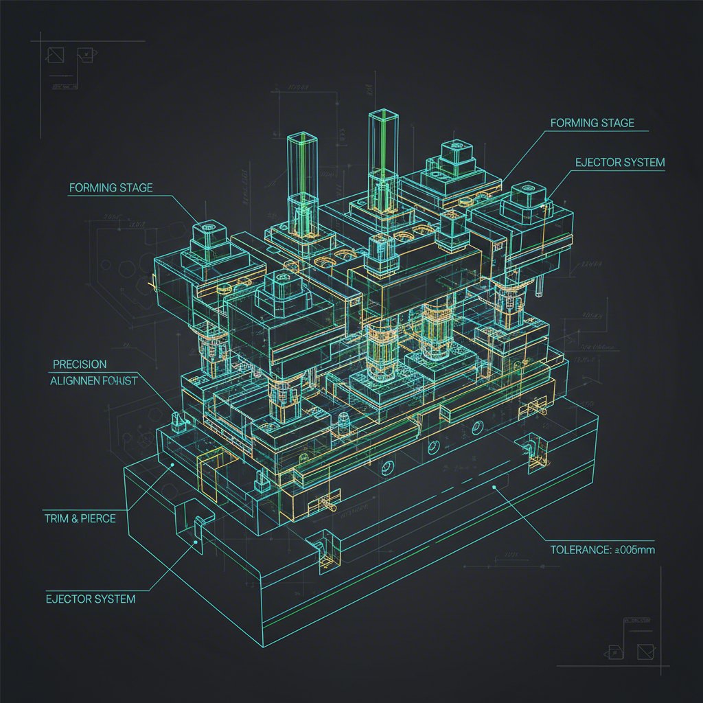
Verktygsdelar och systems integritet för styrning
När grunden är lagd skiftas fokus till integriteten hos arbetande komponenter och styrningssystem. Dessa element – punchar, verktyg, utmatningsplattor och lednitar – utgör verktygets hjärta genom att utföra skär-, form- och materialstyrningsåtgärder. Precisionen och hållbarheten hos dessa komponenter avgör direkt kvaliteten på delarna och hela stansprocessens tillförlitlighet. Varje komponent måste utformas inte bara för sin primära funktion utan även för att fungera i samverkan med de övriga.
Förhållandet mellan stansen och formskäran är av yttersta vikt. Avståndet, eller glappet, mellan stansen och formskärshålan är en av de mest kritiska parametrarna i formdesign. Ett optimalt avstånd, vanligtvis 5–12 % av materialtjockleken, säkerställer en ren skärning med minimala burrar och förlänger verktygslivslängden. Andra komponenter som utmatningsplattor är väsentliga för att hålla plåten på plats och säkerställa en smidig uttagning av stansen efter operationen. För progressiva former spelar pilotstansar en avgörande roll för att exakt positionera materialbandet vid varje station.
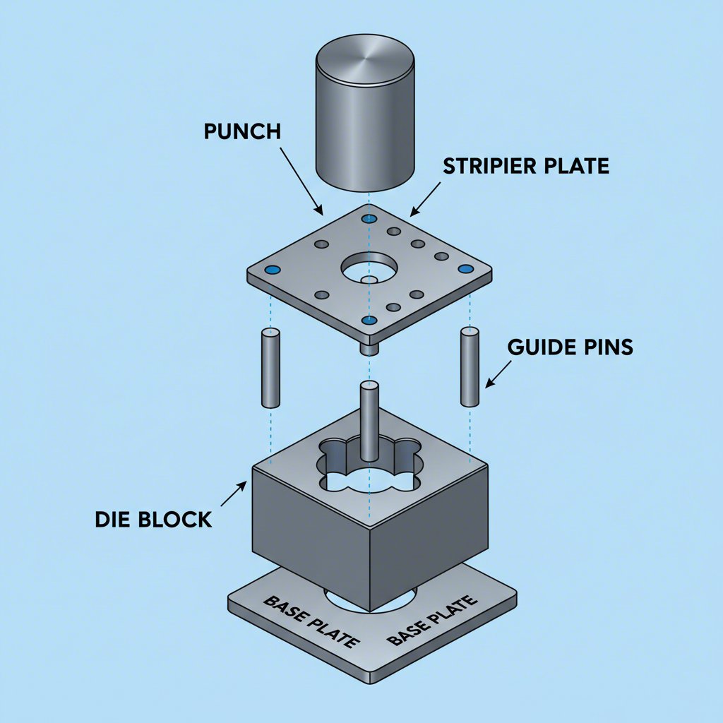
En viktig designfilosofi för att säkerställa komponentintegritet är felinriktning, även känd som Poka-Yoke. Som framhålls i en artikel av Tillverkaren , genom att integrera enkla mekaniska funktioner kan dyra monteringsfel undvikas. Till exempel säkerställer en förskjuten guidepinne eller användning av pinnar med olika diameter att övre och undre formsatser endast kan monteras i rätt orientering. På liknande sätt förhindrar en förskjuten dubb i en komponent att den monteras 180 grader från sin avsedda position. Att säkerställa integriteten för varje komponent är en grundläggande princip för tillverkare som specialiserar sig på kritiska tillämpningar. Till exempel de anpassade stansverktyg för bilindustrin som utvecklats av företag som Shaoyi (Ningbo) Metal Technology Co., Ltd. , är beroende av denna precision för att förhindra komponentfel i kritiska säkerhetssystem.
- Guidepinnar och foder: Är guidepinnarna förskjutna eller har olika diameter för att förhindra felaktig montering?
- Punch-till-die-avstånd: Är avståndet korrekt beräknat utifrån materialtyp och tjocklek (t.ex. 5–12 %)?
- Komponentmontering: Finns minst en skruv eller dubb förskjuten på varje komponent för att säkerställa rätt orientering?
- Utkastarplåtens funktion: Är utmatningsplattan utformad för att effektivt hålla materialet och dra ut det från punscharna?
- Pilotponcher: Finns det pilotponcher för progressiva verktyg för att säkerställa exakt bandposition i varje steg?
- Komponentmaterial: Är alla arbetskomponenter tillverkade av lämpliga verktygstålsgodser (t.ex. A2, D2) och värmebehandlade till rätt hårdhet?
Process, omformning och säkerhetsverifiering
Denna del av checklistan behandlar verktygets dynamiska funktion, med fokus på operationssekvensen, geometrin hos de omformade detaljerna och den övergripande processsäkerheten. Medan tidigare avsnitt bekräftade verktygets statiska integritet, validerar detta avsnitt dess förmåga att tillverka komponenten korrekt och effektivt. Det innebär en djupgående analys av metallomformningens fysik och logiken i processsekvensering.
Arbetsordningen, särskilt i en progressiv verktyg, följer strikt logik. En gyllene regel är att utföra plana operationer innan formsättande operationer ("platt före form") och att perforera inre detaljer innan man avskär den yttre konturen ("inifrån innan utifrån"). Detta förhindrar deformation av detaljer som skapats i tidigare steg. Bandet självt måste utformas så att det har tillräcklig strukturell integritet för att bära delen genom alla stationer utan att gå sönder eller deformeras.
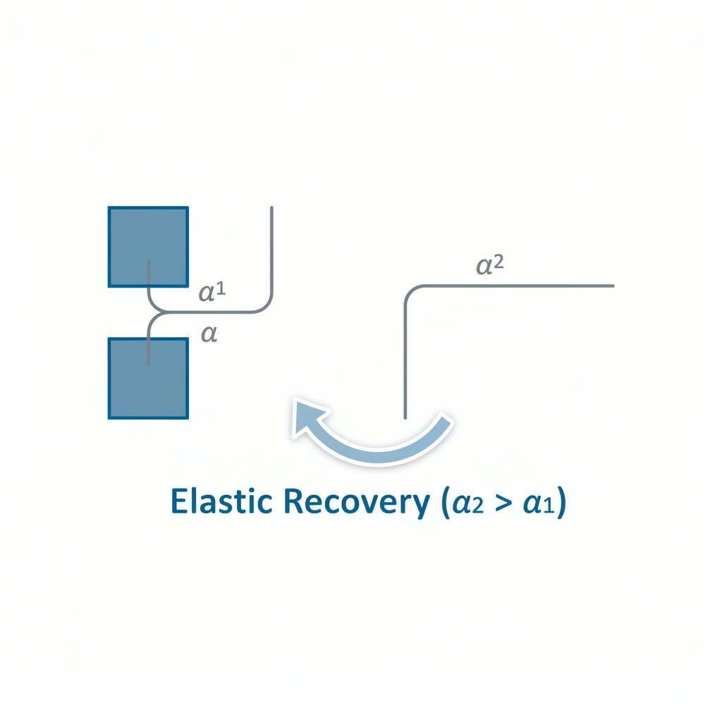
Att verifiera geometrin för formade detaljer är avgörande för tillverkningsbarhet. Enligt riktlinjer för plåtdesign måste varje böj, hål och prägling följa etablerade tekniska regler för att förhindra materialskador, deformation eller brott. Till exempel bör inre böjradie i allmänhet vara minst lika stor som materialtjockleken. När en böj placeras för nära ett hål kan hålet deformeras till en tårform. För att förhindra detta måste avståndet från hålet till böjen vara tillräckligt, vanligtvis minst 2,5 gånger materialtjockleken plus böjradie. Ett annat viktigt begrepp är återfjädring, där metallen elastiskt återhämtar sig efter formning. Konstruktörer måste ofta inkludera överböjning för att kompensera för denna effekt och uppnå önskad slutvinkel.
| Detalj/Process | Regel/Formel | Syfte |
|---|---|---|
| Processsekvens | Platt innan form; innanför innan utanför. | Förhindrar deformation av tidigare skapade detaljer. |
| Inre böjradie (r) | r ≥ materialtjocklek (t). | Förhindrar materialsprickbildning på ytterradie. |
| Böjrelief | Avtappningsbredd ≥ t; Avtappningsdjup > r. | Förhindrar materialbristning när en böj utförs nära en kant. |
| Avstånd från hål till böj | Avstånd ≥ 2,5t + r. | Förhindrar deformation av hål under böjning. |
| Kvarvarande deformation vid återfjädring | Konstruktionen inkluderar överböjning för att motverka elastisk återfjädring. | Säkerställer att slutliga delvinkeln uppfyller specifikationerna. |
Verktygsöverföring och slutlig verifieringsprotokoll
Ett ofta översett men kritiskt steg i ett verktygs livscykel är dess överföring mellan anläggningar eller från verktygstillverkare till produktionsslagare. En dåligt hanterad överföring kan leda till betydande produktionsavbrott, kvalitetsproblem och förlorad kunskap. En omfattande checklista för verktygsöverföring säkerställer en smidig övergång och skyddar den stora investering som gjorts i verktyget. Detta protokoll fungerar som den slutliga verifieringen innan ett verktyg skickas eller tas emot i en ny produktionsmiljö.
Kärnan i en lyckad överföring är komplett och korrekt dokumentation. Enligt experter på Manor Tool går detta långt bortom endast den fysiska verktygsdelen. Den måste inkludera kompletta ritningar för verktyget i både pappersform och CAD-format, detaljerade procedurer för montering och avlusning av verktyget samt en omfattande reservdelslista. Denna dokumentation gör att mottagande anläggning kan driva, underhålla och reparera verktyget effektivt utan att behöva förlita sig på det ursprungliga byggaren.
Den fysiska överföringen kräver sina egna verifieringar. Verktyget måste vara säkert fäst vid transportkorgen för att förhindra skador under transporten. Allt fraktade dokumentation, inklusive försändelsesedel och eventuella tulldeklarationer, måste vara korrekt. Slutligen ska en fullständig verifiering av verktygets nyckelparametrar utföras och dokumenteras. Detta inkluderar bekräftelse av stängningshöjd, totala verktygsdimensioner, materialspecifikationer och tonnagekrav. Att inkludera ett slutgiltigt provband från den senaste produktionen ger en tydlig referens för verktygets prestanda vid ankomsten.
Kontrollista för verktygsöverföring:
- Kompletta verktygsritningar: Bekräfta att både papperskopior och CAD-filer finns med.
- Förfaranden och dokumentation: Verifiera att installationsförfaranden, service/reparationsdokumentation och fullständig kvalitetskontroll av komponenter finns med.
- Dokumentation för reservdelar: Se till att en lista över reservdelar, lagersaldo och kontaktuppgifter till leverantörer finns med.
- Slutgiltigt provband: Kontrollera att ett provstråk som representerar den senaste materialkörningen finns med i verktyget.
- Säkerhet vid frakt: Verifiera att verktyget är säkert fastspänt vid sin transportlåda.
- Slutlig parameterverifiering: Bekräfta och dokumentera följande kritiska data:
- Stängd höjd
- Verktygsdimensioner och vikt
- Tonnkrav
- Materialspecifikation (tjocklek och bredd)
Vanliga frågor
1. Vad är det vanligaste felet vid design av plåtslagerverktyg?
Ett av de vanligaste och mest kostsamma felen är otillräcklig planering för materialens egenskaper, särskilt återfjädring. Designörer som inte korrekt kan förutsäga och kompensera för hur metallen elastiskt återhämtar sig efter omformning kommer att tillverka delar med felaktiga vinklar och mått. Detta leder ofta till dyra och tidskrävande omarbetningar av det hårdade verktygsstålet.
2. Varför är felsäkerhet (Poka-Yoke) viktig i verktygsdesign?
Felsäkerhet är avgörande eftersom den förhindrar felmontering av verktyget, vilket kan leda till katastrofala skador på verktyget och pressen. Enkla designfunktioner, som att förskjuta en ledpinne eller använda dubbler med olika storlek, gör det fysiskt omöjligt att montera komponenter felaktigt, vilket sparar betydande tid och pengar på reparationer och driftstopp.
3. Hur beräknas klarans mellan stans och matris?
Klaransen mellan stans och matris beräknas vanligtvis som en procentandel av plåtens tjocklek. Den exakta procenten beror på materialets hårdhet och seghet. För mjuka material som aluminium är en klarans på cirka 5–8 % per sida vanlig. För hårdare material som höghållfast stål kan klaransen öka till 15–20 % per sida. Felaktig klarans kan leda till stora burrar, överdriven stanskraft och snabb verktygsslitage.