 Малые партии, высокие стандарты. Наша служба быстрого прототипирования делает проверку точнее и проще —

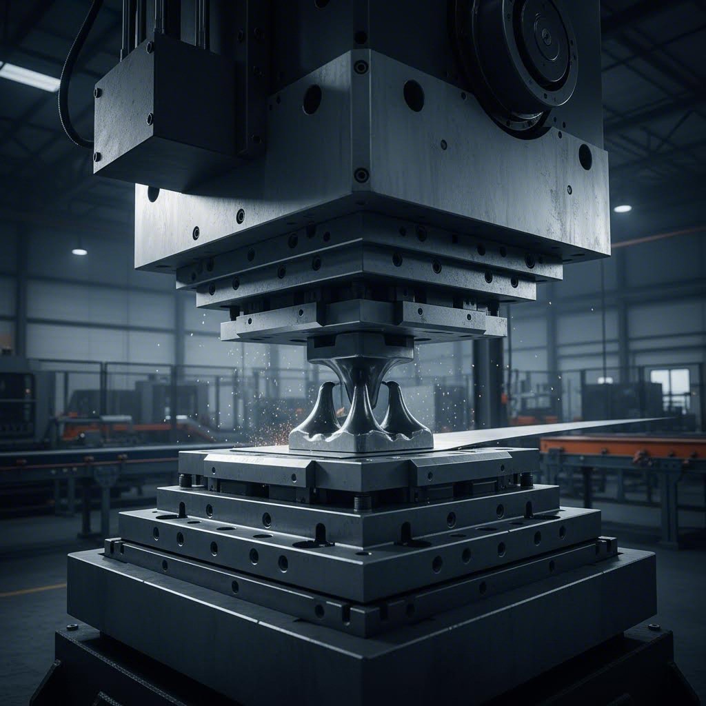
Секреты прессов для металлических матриц: от расчёта усилия до безупречных деталей
Что такое пресс для штамповки металла и как он работает
Задумывались ли вы когда-нибудь, каким образом производители превращают плоские металлические листы в сложные кузовные панели автомобилей или корпуса смартфонов? Ответ кроется в мощном оборудовании, которое составляет основу современной обработки металлов — прессе для штамповки металла.
Пресс для штамповки металла — это станок, использующий специальную оснастку (штампы) для резки, формовки или придания формы металлическим листам под контролируемым давлением с использованием свойств пластической деформации металла с целью получения точных и повторяемых деталей.
Если задуматься, этот процесс выглядит удивительно элегантно. Пресс-машина для штамповки прикладывает колоссальное усилие, чтобы зажать металл между специально разработанными инструментами, необратимо изменяя форму материала — от простых кронштейнов до сложных корпусов электронных устройств. После снятия усилия металл сохраняет новую форму — свойство, которое производители используют уже десятилетиями для выпуска миллионов идентичных деталей.
Основной механизм формовки металла
Итак, что же на самом деле делает станок для вырубки при работе? Фундаментальный принцип основан на пластической деформации — свойстве металлов необратимо изменять форму без разрушения. В отличие от упругих материалов, которые возвращаются в исходное состояние, металлы сохраняют новую форму после завершения работы пресса и штампа.
Здесь терминология зачастую вызывает путаницу. Хотя люди иногда используют термины «пресс-машина для штамповки металла» и «штамповочный пресс» как взаимозаменяемые, между ними существует важное различие. Под пресс-машиной для штамповки конкретно подразумевается оборудование с использованием штампов нестандартной формы, специально разработанных для производства конкретных деталей . Универсальные штамповочные прессы, напротив, могут использовать стандартизированную оснастку для выполнения более простых операций. Представьте это следующим образом: каждый штамповочный пресс выполняет штамповку, однако именно штамп, устанавливаемый на пресс, определяет специализацию машины для изготовления конкретных компонентов.
От исходного листа до прецизионной детали
Представьте себе плоский лист стали, поступающий в систему штампов пресса. В течение нескольких секунд он выходит из неё уже в виде точно сформированной детали — например, кронштейна, панели или декоративной отделочной детали. Такое преобразование осуществляется посредством ряда возможных операций:
- Резка и вырубка - пробивка фигур из листового металла
- Сгибание - формирование углов и изгибов
- Рисунок - создание трёхмерных форм, таких как стаканы или ёмкости
- Тиснение - нанесение выпуклых узоров или рисунков
Применения этой технологии повсюду вокруг вас. Автомобильные производители используют эти станки для изготовления кузовных панелей и несущих компонентов. Электронные компании применяют их для корпусов устройств и радиаторов. Даже бытовая техника на вашей кухне содержит детали, полученные штамповкой на пресс-форме. Согласно эксперты отрасли , штамповка применяется в автомобильной промышленности, электронике, мебельном производстве и бытовой технике благодаря своей способности гибко обрабатывать металлы.
Что делает эту технологию столь ценной? Скорость и стабильность. После изготовления оснастки штамповочная пресс-форма способна выпускать тысячи идентичных деталей с выдающейся эффективностью. Именно сочетание точности, воспроизводимости и скорости производства делает металлические штамповочные прессы незаменимым оборудованием на производственных предприятиях по всему миру.
Основные компоненты системы металлического штамповочного пресса
Теперь, когда вы понимаете, для чего предназначена пресс-форма для металла, давайте приподнимем капот и рассмотрим, что на самом деле находится внутри. Знание этих компонентов помогает вам оценивать оборудование, устранять неисправности и эффективно взаимодействовать с поставщиками оснастки. Рассматривайте это как урок анатомии станков для пресс-форм: как только вы поймёте, как функционирует каждый элемент, вся система станет гораздо понятнее.
Понимание пресс-форм и их функций
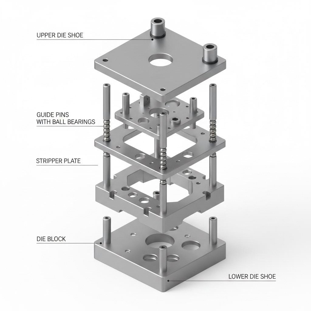
Пресс-форма является «сердцем» каждой операции на пресс-форме для металла. Согласно инженерные справочники , пресс-форма состоит из нижней плиты (плиты матрицы) и верхней плиты, обе из которых обработаны с высокой точностью так, чтобы быть параллельными друг другу с отклонением в доли тысяч дюйма. Эти прецизионные поверхности служат основой, на которой монтируются все остальные компоненты оснастки.
Вот что происходит во время работы: верхняя плита крепится к ползуну пресса (подвижной части), а нижняя плита — к неподвижной плите пресса. Когда ползун опускается, он перемещает пуансон — мужскую часть инструмента — вниз в матрицу, которая содержит женские режущие или формующие поверхности. Листовой металл, зажатый между ними, приобретает постоянную форму.
Следующие компоненты работают совместно для реализации этого процесса:
- Плиты штампа - Стальные или алюминиевые пластины, служащие основой для крепления всех остальных компонентов штампа. Они должны сохранять точную параллельность, чтобы обеспечить стабильное качество деталей.
- Матрица - Закреплённый на нижней плите блок из закалённой инструментальной стали, содержащий матричные кнопки, гнёзда и отверстия, определяющие форму детали.
- Пластина пуансонов - Устанавливается на верхнюю плиту; эта закалённая стальная пластина удерживает все пуансоны, направляющие и пружинные компоненты.
- Пуансоны штампа - Режущие или формовочные инструменты, вдавливающиеся в металл. Доступны в различных конфигурациях носика: круглой, овальной, квадратной и специальной.
- Вставки штампа - Элементы, противоположные пуансонам, обеспечивающие противоположную режущую кромку. Обычно их размер превышает размер пуансона на 5–10 % толщины обрабатываемого материала для обеспечения необходимого зазора в штампе.
- Съемники - Компоненты, снимающие листовой металл с пуансона после каждого хода. Могут быть неподвижными (установленными на блоке матрицы) или пружинными (закреплёнными на пластине пуансона).
- Опорные пластины - Устанавливаются между блоками матриц и подошвами штампов, чтобы предотвратить вдавливание пуансонов и матриц в более мягкий материал подошвы.
Роль подошв штампов и систем направляющих
Точная центровка верхней и нижней половин штампа имеет принципиальное значение. Даже микроскопическое несоосное положение приводит к неравномерному износу, образованию заусенцев на готовых деталях и преждевременному выходу оснастки из строя. Именно здесь направляющие штифты и втулки проявляют свою ценность.
Направляющие штифты — также называемые направляющими стойками — это точно отшлифованные стальные штифты надежно закреплены в нижней половине штампа. Они изготавливаются с допусками не более 0,0001 дюйма (одна десятитысячная дюйма), чтобы обеспечить точное позиционирование при каждом ходе.
В конфигурациях комплектов штампов для прессов вы встретите два основных типа направляющих систем:
- Направляющие штифты с шариковыми подшипниками - Эти штифты перемещаются по последовательности шариковых подшипников, расположенных в алюминиевой обойме, что упрощает разъединение половин штампа и снижает трение при высокоскоростных операциях. Они стали отраслевым стандартом для большинства применений.
- Направляющие штифты трения (гладкие) - Их диаметр несколько меньше внутреннего диаметра втулок; они обеспечивают точное направление, однако для разъединения половин штампа требуется большие усилия. Тем не менее они остаются востребованными там, где необходима максимальная жёсткость.
При выборе наборов штампов для прессов вы также выбираете между открытыми наборами штампов и наборами штампов с направляющими колоннами. В открытых наборах направляющие штифты полностью отсутствуют — они недороги, но требуют тщательной настройки и лучше всего подходят для простых деталей с большими допусками. Наборы штампов с направляющими колоннами включают две или четыре направляющие колонны; конфигурации с четырьмя колоннами обеспечивают максимальную точность при обработке материалов большой толщины или при использовании крупногабаритных штампов.
Ключевые термины, которые вам необходимо знать
При оценке штампов для станков или обсуждении технических характеристик с поставщиками вы столкнётесь с рядом ключевых терминов:
- Ход - Расстояние, которое проходит ползун пресса от верхнего до нижнего положения. Более длинный ход позволяет использовать более высокие штампы, однако может снижать производительность.
- Грузоподъемность - Максимальное усилие, которое пресс способен развить, измеряемое в тоннах. От этого параметра зависит, какие материалы и их толщины можно обрабатывать.
- Зазор матрицы - Зазор между пуансоном и матрицей, обычно составляющий 5–10 % толщины материала. Слишком малый зазор вызывает чрезмерный износ инструмента; слишком большой — приводит к образованию заусенцев и неровных кромок.
- Высота замыкания - Расстояние между наружными поверхностями верхней и нижней плит матрицы, когда матрица полностью закрыта. Это значение должно соответствовать техническим характеристикам вашего пресса.
Понимание этих базовых принципов кардинально меняет подход к выбору оборудования. Вместо ощущения перегрузки техническими спецификациями вы теперь можете оценить, соответствуют ли конкретные наборы матриц вашим производственным требованиям — это основа, которая становится критически важной при расчёте необходимого усилия (в тоннах) для ваших задач.
Типы прессов для металлических штампов и их применение
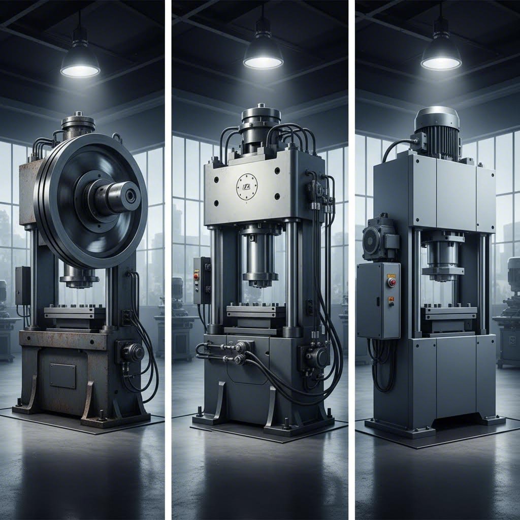
Разобрав компоненты, перейдём к следующему логическому вопросу: что именно создаёт всё это усилие? Ответ определяет всё — от скорости производства до качества деталей. Прессы для металлических штампов подразделяются на три основные категории в зависимости от типа привода, и правильный выбор пресса может обеспечить или, напротив, свести на нет эффективность вашего производства.
Механические и гидравлические прессовые системы
Механические прессы десятилетиями доминировали на производственных площадках — и на то есть веские причины. Эти станки используют систему маховика и кривошипно-шатунного механизма для создания усилия. Маховик накапливает вращательную энергию, которая передаётся через коленчатый вал для перемещения ползуна вниз. Согласно Техническому сравнению Stamtec , традиционные механические прессы обеспечивают наибольшую производительность, особенно при обработке относительно плоских деталей с более простыми и менее глубокими требованиями к формованию.
В чём секрет высокой скорости механических систем? В их простоте. Энергия уже накоплена во вращающемся маховике и готова к мгновенному высвобождению. Машины для вырубки штампами с механическим приводом способны выполнять сотни циклов в минуту при высокопроизводительных операциях штамповки. Автомобильная, бытовая и крепёжная промышленность активно использует эту технологию при прогрессивной штамповке, где решающее значение имеет скорость.
Гидравлические прессы используют совершенно иной подход. Вместо запасенной механической энергии они применяют давление жидкости — как правило, масла, нагнетаемого в цилиндр — для перемещения ползуна. Такая конструкция обеспечивает то, чего не могут дать механические прессы: полную номинальную силу на любом участке хода. Набор штампов для гидравлического пресса может прикладывать максимальное усилие независимо от того, находится ли ползун в верхнем, среднем или нижнем положении своего хода.
Эта гибкость делает штампы для гидравлических прессов предпочтительным выбором при операциях глубокой вытяжки. При формировании резервуаров, цилиндров, чашеобразных деталей или любых других изделий, требующих значительного перемещения материала, возможность приложения постоянного давления на протяжении всего хода предотвращает разрывы и обеспечивает более качественный результат. Оснастка для гидравлических прессов также особенно эффективна при операциях, требующих «выдержки» — удержания давления в нижней точке хода в течение определённого времени.
Что же касается компромисса? Это скорость. Гидравлические системы принципиально не способны достичь скоростей циклирования механических прессов. Кроме того, они, как правило, обладают меньшей точностью и повторяемостью, о чём упоминается в сравнение отраслей однако при сложном формовании, где важнее точность, а не объем, гидравлические системы обеспечивают результаты, которых механические прессы с трудом достигают.
Когда применение сервотехнологии оправдано
А что, если объединить механическую скорость и гидравлическую гибкость? Именно это и достигают прессы с серводвигателем. В этих станках традиционный маховик, муфта и тормоз заменены высокомощными серводвигателями, способными обеспечивать полную рабочую энергию при любой скорости — в том числе и при выдержке.
Разница кардинальна. По данным инженерной команды Stamtec, сервопрессы могут изменять скорость на протяжении всего хода — быстро проходя нерабочие участки и замедляясь до оптимальной скорости формовки при контакте с материалом. Благодаря этой возможности некоторые производители удвоили свой выпуск продукции.
Промышленный станок для штамповки с сервотехнологией обеспечивает программируемые профили хода, включая:
- Циклы глубокой вытяжки - Более низкие скорости формовки при полной энергии
- Многоходовые операции - Несколько операций формовки за один цикл
- Режим маятника - Регулируемая длина хода (использование только 2, 4 или 6 дюймов полного хода в 8 дюймов)
- Симулированное движение шарнирного механизма - Воспроизведение характеристик специализированных механических прессов
The промышленная машина для штамповки привод на основе сервотехнологии особенно эффективен в сценариях консолидации. Сервопресс часто способен выполнить больше операций вытяжки и формовки на одной станции, чем традиционный механический пресс — на нескольких станциях. Это означает меньшее количество прессов, уменьшенные размеры рабочих поверхностей для штампов и снижение требований к площади производственного помещения.
Разумеется, сервопрессы имеют более высокую первоначальную стоимость. Двигатели, системы управления и возможности программирования требуют значительных инвестиций. По своей сути они остаются механическими прессами и обеспечивают максимальную номинальную силу близко к нижней мёртвой точке хода. Для применений, требующих полной номинальной силы на протяжении всего хода, гидравлические прессы по-прежнему обладают преимуществами в плане конструкции штампов.
| Фактор | Механический пресс | Гидравлическая пресса | Сервопресс |
|---|---|---|---|
| Скоростная способность | Наивысшая — идеальна для массового производства | Самая медленная — подходит для сложных операций формовки | Высокая — приближается к механическим скоростям с гибкостью |
| Доступность в тоннажах | Полная мощность только вблизи нижней точки хода | Полная мощность в любой точке хода | Полная мощность вблизи нижней точки хода |
| Уровень точности | Высокая точность и повторяемость | Низкая точность и воспроизводимость | Высокая точность с программируемым управлением |
| Энергоэффективность | Эффективна — использует накопленную энергию маховика | Более высокое энергопотребление при полной мощности | Эффективна — полная энергия при любой скорости |
| Гибкость хода | Фиксированная длина хода (обычно) | Регулируемая длина хода | Полностью программируемые профили хода |
| Начальные затраты | Относительно низкая | Относительно низкая | Относительно высокая |
| Лучшие применения | Прогрессивные штампы, вырубка, простое формование | Глубокая вытяжка, сложные формы, операции с выдержкой | Сложное формование, уплотнение, переменный объём производства |
Выбор между этими технологиями полностью зависит от ваших производственных требований. Запуск плоских автомобильных штамповок в максимальном объёме? Механические прессы по-прежнему остаются эталоном. Формование глубоких цилиндрических деталей, требующее тщательного контроля за течением материала? Гидравлические прессы обеспечивают необходимый уровень управления. Нужна универсальность для обработки различных типов деталей при высокой скорости? Сервоприводы оправдывают свои более высокие капитальные затраты.
Понимание особенностей этих приводных механизмов даёт вам значительное преимущество при расчёте требуемой силы прессования (в тоннах) и совместимости с обрабатываемыми материалами для ваших конкретных задач — ключевых расчётов, которые в конечном счёте определяют, какой размер пресса необходим вашему производству.
Расчёт усилия прессования (в тоннах) и совместимость с материалами
Вы ознакомились с типами оборудования. Теперь наступает вопрос, который разделяет успешные операции и дорогостоящие ошибки: какое усилие действительно требуется для вашего применения? Ошибки в этом расчёте приводят к серьёзным проблемам. Если вы будете обрабатывать деталь на прессе недостаточной мощности, это вызовет усталость оборудования, его повреждение и значительный простой. Если же вы будете использовать пресс избыточной мощности, эффективность резко снизится, а затраты возрастут. Давайте подробно разберём расчёт, чтобы вы могли правильно подобрать пресс для штамповки листового металла с самого начала.
Расчёт требуемой мощности (в тоннах)
Базовый расчёт мощности включает три ключевых параметра: длину реза (периметр), толщину материала и сопротивление материала срезу. Для операций пробивки и обрезки формула выглядит следующим образом:
Мощность (тонны) = Периметр (мм) × Толщина (мм) × Сопротивление срезу (кгс/мм²) × Коэффициент запаса прочности (1,1–1,2) ÷ 1000
Звучит просто? А вот здесь начинается самое интересное. Согласно исследованиям партнерства Auto/Steel, устаревшие эмпирические правила, которые работали десятилетия назад, сегодня зачастую недооценивают требуемую тоннажную нагрузку — особенно при использовании современных сталей повышенной прочности (AHSS). Эти новые материалы обладают вдвое большей прочностью по сравнению с традиционными высокопрочными сталями при сопоставимой формоустойчивости, что многократно усиливает влияние любых погрешностей в расчётах.
Рассмотрим практический пример из Расчётных формул Keyence для механической обработки : пробивка нержавеющей стали марки SUS304 с периметром реза 100 мм, толщиной 3 мм и пределом прочности на срез 53 кгс/мм² требует приблизительно 17,49 тонны усилия — при коэффициенте запаса прочности 1,1. Замените материал на низкоуглеродистую сталь с пределом прочности на срез 35 кгс/мм² — и требуемое усилие снизится примерно до 11,5 тонны. Выбор материала кардинально влияет на подбор штампов для пресса.
Следующие факторы напрямую влияют на расчёт требуемого тоннажа:
- Периметр реза - Общая длина контура детали, подвергаемой обрезке, пробивке или вырубке. Более сложные формы с увеличенным периметром требуют большего усилия (в тоннах).
- Толщина материала - Увеличение толщины заготовки пропорционально повышает требуемое усилие. Однако при фактической резке разрушение материала происходит уже при проникновении инструмента на 20–50 % от его полной толщины, то есть вся толщина материала не всегда участвует в процессе.
- Сопротивление сдвигу - Как правило, оценивается как 60 % предела прочности на разрыв, хотя это значение варьируется в зависимости от микроструктуры материала. Для сталей АНСС (AHSS) данное допущение особенно проблематично.
- Зазор матрицы - Уменьшение зазоров между матрицей и пуансоном увеличивает силу трения и требуемое усилие. Конструкция вашей комплектной металлической оснастки напрямую влияет на необходимое усилие (в тоннах).
- Метод резки - Наклонные режущие кромки пуансонов снижают мгновенное усилие за счёт распределения процесса резания по всему ходу инструмента.
- Смазка - Правильная смазка уменьшает силу трения между режущими элементами оснастки и заготовкой, что снижает требуемое усилие.
Для операций гибки расчёт изменяется. Необходимо учитывать длину изгиба, ширину V-образной матрицы, толщину материала и предел прочности на разрыв. Также применяется поправочный коэффициент, основанный на соотношении ширины V-образной матрицы к толщине материала. Операции формовки и вытяжки становятся ещё более сложными и требуют учёта площади поверхности, характера течения материала и свойств упругого восстановления («отскока»).
Толщина материала и грузоподъёмность пресса
Различные металлы по-разному ведут себя под давлением, и ваши штампы должны обеспечивать компенсацию этих различий. Ниже приведена информация о наиболее распространённых материалах:
Мягкая сталь сталь низкоуглеродистая остаётся наиболее щадящим вариантом для операций резки металла штампами. При пределе прочности около 44 кгс/мм² (примерно 430 МПа) она формуется предсказуемо и допускает более широкие диапазоны зазоров в штампах. Большинство стандартных расчётов требуемой силы прессования были разработаны с использованием низкоуглеродистой стали в качестве базового материала.
Нержавеющая сталь требует значительно большего усилия — примерно на 20 % выше, чем для низкоуглеродистой стали при сопоставимой толщине. Например, предел прочности стали марки SUS304 составляет 53 кгс/мм². Кроме того, материал упрочняется при обработке давлением, то есть сопротивление возрастает на каждой последующей операции штамповки.
Алюминий представляет противоположную задачу. Более низкий предел прочности (около 10–30 кгс/мм² в зависимости от сплава) означает, что требуется меньшее усилие пресса, однако мягкость материала требует более точной подгонки зазоров в штампах, чтобы предотвратить чрезмерное образование заусенцев. Конструкция ваших штампов для листового металла должна быть скорректирована с учётом склонности алюминия к задиру при контакте с рабочими поверхностями инструмента.
Медь и латунь занимают промежуточное положение: они обладают умеренной прочностью и отличной формоустойчивостью. Эти материалы часто выбираются для электрических компонентов, где важнее электропроводность, чем конструкционная прочность.
Высокопрочные стали нового поколения представляют собой самую сложную задачу с точки зрения расчётов. При пределе прочности до 1500 МПа и выше — в три–пять раз превышающем показатель низкоуглеродистой стали — любая погрешность в оценках многократно усиливается. Исследование партнёрства «Автомобильная промышленность / Сталь» описывает случаи, когда, казалось бы, небольшие детали, требующие скромного тоннажа, на самом деле нуждаются в прессах вдвое большего размера для обеспечения достаточного энергетического потенциала.
Почему ошибки при выборе тоннажа пресса обходятся дорого
Выбор пресса с недостаточным тоннажем вызывает немедленные проблемы. При превышении пиковых нагрузок над допустимой грузоподъёмностью существует риск повреждения рамы, ползуна, втулок и элементов привода. Даже если повреждение не происходит сразу, постоянная эксплуатация вблизи максимальной нагрузки ускоряет износ и приводит к преждевременным отказам.
Однако вот что многие упускают из виду: тоннаж — это не единственное важное соображение. Не менее важна общая энергия, затрачиваемая на ход ползуна. Механический пресс может обладать достаточным пиковым тоннажем в нижней мёртвой точке, но тем не менее останавливаться, поскольку его маховик не способен накопить достаточно энергии для завершения операции формовки. Такое явление возникает чаще всего при работе с материалами АНСС (сталью повышенной прочности), которые требуют поддержания значительного усилия на протяжении существенного хода ползуна.
Избыточный запас прочности создает различные проблемы. Например, в ходе промышленных исследований был рассмотрен случай с кронштейном рамы — небольшая деталь из высокопрочной стали (AHSS) размером 6" × 6", теоретически подходящая для пресса грузоподъемностью 600 тонн, на практике требовала пресса мощностью 1200 тонн для обеспечения достаточного энергетического потенциала. Установка небольшой оснастки в центре рабочего стола пресса шириной 180 дюймов вызывала эргономические трудности для операторов, замедляла цикл штамповки и значительно повышала удельные эксплуатационные расходы.
Каково решение? Отказаться от упрощенных эмпирических правил. Современная передовая практика объединяет метод конечных элементов (МКЭ) с точной характеристикой свойств материалов. Программное обеспечение позволяет прогнозировать не только пиковую нагрузку, но и кривые усилия по всей длине хода пресса, а также распределение нагрузки при эксцентричной установке оснастки. Эти данные помогают выбрать штампы и оборудование, соответствующие реальным требованиям производства, а не завышенным оценкам «наихудшего случая».
После определения требуемой номинальной силы пресса следующим важнейшим фактором становится проектирование штампа — в частности, влияние зазоров, стратегий формообразования и выбора инструментов на качество готовых деталей.
Основы проектирования штампов для обеспечения высокого качества продукции
Вы рассчитали требуемое усилие и выбрали тип пресса. Теперь наступает этап, который в конечном счёте определяет, будете ли вы получать безупречные детали или бракованные изделия: проектирование штампа. Штамп, который вы используете — его геометрия, зазоры и конструкция — напрямую влияет на качество кромок, точность размеров и срок непрерывной работы оборудования до необходимости технического обслуживания. Рассмотрим, чем точные штампы отличаются от проблемных.
Зазор штампа и его влияние на качество деталей
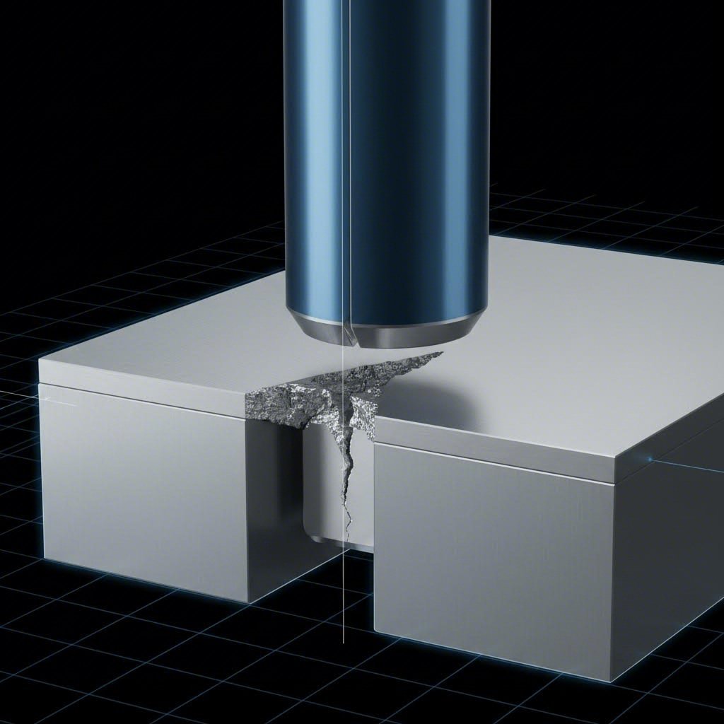
Зазор штампа — это расстояние между режущей кромкой пуансона и режущей кромкой матрицы — может показаться незначительной деталью. На самом деле это единственный наиболее критичный фактор успеха процесса пробивки. Согласно обширным исследованиям компании Dayton Lamina, в ходе которых было проведено более 10 000 испытаний различных зазоров, оптимизация этого расстояния кардинально влияет на высоту заусенца, ресурс инструмента и общее качество отверстий.
Вот что происходит при вырубке: когда пуансон проникает в материал, трещины возникают на режущих кромках как пуансона, так и матрицы — как на верхней, так и на нижней поверхностях листа. При правильном зазоре эти трещины соединяются чисто, что обеспечивает аккуратное отделение вырубаемой заготовки («слага») и плавное снятие усилия вырубки.
Что происходит при неправильном зазоре? Распространённой ошибкой является выбор слишком малого зазора с предположением, что это улучшит качество кромки. На самом деле происходит обратное. При недостаточном зазоре верхняя и нижняя трещины практически не пересекаются, что приводит к образованию вторичных трещин и двойных надломов. Кроме того, материал сильнее «захватывает» пуансон, что увеличивает силы снятия и вызывает абразивный износ, сокращающий срок службы как пуансона, так и матрицы.
Традиционное отраслевое эмпирическое правило — 5 % от толщины заготовки с каждой стороны — даёт приемлемые результаты во многих случаях. Однако исследования Dayton по инженерному подбору зазоров показывают, что значительно увеличенные зазоры (до 28 % с каждой стороны для некоторых материалов) могут фактически снизить высоту заусенца, повысить срок службы пуансона и улучшить качество отверстий. Оптимальный зазор зависит от следующих факторов:
- Наличие толщины - Более толстые материалы, как правило, допускают более широкие зазоры
- Предел прочности материала при растяжении - Для сталей повышенной прочности требуются иные процентные значения зазора по сравнению с низкоуглеродистой сталью
- Твёрдость материала - Более твёрдые материалы (измеряемые по шкалам Бринелля или Роквелла) ведут себя иначе в процессе разрушения
- Требования к применению - От того, какой параметр вы ставите во главу угла: длина полированного участка, высота заусенца или срок службы инструмента
Срезы, которые формирует ваша штамповочная матрица, рассказывают свою историю. Оптимальный зазор в матрице обеспечивает получение срезов с равномерной полированной поверхностью, составляющей примерно одну треть толщины материала, а также с ровной плоскостью разрушения, совмещённой с этой полированной поверхностью. Неровные плоскости разрушения и чрезмерные заусенцы указывают на слишком большой зазор. Нерегулярные плоскости разрушения, неравномерная полировка и вторичный срез свидетельствуют о недостаточном зазоре.
Проектирование с учётом точности и долговечности
Помимо зазора, несколько принципов проектирования матриц определяют, будет ли ваша оснастка обеспечивать стабильные результаты в течение тысяч — или даже миллионов — циклов. Штамповочные прессы для резки требуют оснастки, спроектированной специально под конкретные нагрузки, с которыми она будет сталкиваться.
Формовочные матрицы сталкиваются с иными задачами по сравнению с режущими матрицами. При формировании металла методами гибки, вытяжки или тиснения критически важным становится поведение материала. Согласно инженерным рекомендациям компании PEKO Precision, эффективное проектирование инструментов и матриц требует глубокого понимания как свойств материалов, так и механических процессов, задействованных в операции.
Гибочные матрицы для листового металла вызывают явление, с которым должен считаться каждый конструктор: упругое отдаивание (отскок). После снятия силы изгиба материал частично возвращается к своей первоначальной форме вследствие упругого восстановления. Исследование компании CHAOERO подтверждает, что величина упругого отдаивания зависит от предела текучести материала, модуля упругости, радиуса изгиба, угла изгиба и толщины листа.
Формула компенсации упругого отдаивания служит отправной точкой:
δθ (угол перегиба) = θ × (E × t) / (2 × σ × R)
Где θ — требуемый угол изгиба, E — модуль упругости, t — толщина, σ — предел текучести, а R — радиус изгиба. Операторы используют эту формулу для расчёта углов предварительной компенсации при высокоточном гибочном процессе.
Прогрессивные штампы представляют собой наиболее сложный подход к проектированию штамповой оснастки. Несколько операций выполняются последовательно по мере продвижения заготовки через станции за один цикл пресса — пробивка, гибка, формовка и обрезка происходят в рамках одного комплекта штампов. Согласно анализу компании PEKO, инженерам необходимо учитывать правильное выравнивание пуансонов и матричных полостей, характеристики упрочнения материала при деформации, а также конструкцию системы подачи, обеспечивающую плавное перемещение заготовки.
Ключевые аспекты проектирования штампов, влияющие как на качество, так и на срок службы, включают:
- Анализ течения материала - Прогнозирование поведения металла в процессе формовки предотвращает истончение, разрывы и образование морщин. Имитационное моделирование с применением CAE помогает оптимизировать форму заготовки и геометрию штампа до начала механической обработки стали.
- Компенсация пружинения - Введение избыточных углов гибки в гибочные штампы, корректировка радиусов пуансонов и оптимизация времени выдержки в нижней точке хода позволяют компенсировать упругое восстановление.
- Износостойкость - Выбор инструментальной стали (A2, D2 или легированные стали) в зависимости от ожидаемого объема производства и обрабатываемого материала. Более твердые материалы требуют более твердого инструмента.
- Силы снятия - Проектирование надежных систем снятия предотвращает прилипание материала к пуансонам при их извлечении. Стружкосъемники с пружинным приводом или пуансоны с системой выталкивания снижают вероятность захвата отходов («слагов»).
- Системы направляющих отверстий - Прецизионные направляющие отверстия обеспечивают точное позиционирование материала на каждой станции прогрессивного штампа, поддерживая заданные допуски при многостанционной обработке.
Допуски и уровни точности
Какую точность можно реально ожидать от прессов для штамповки? Это зависит от качества штамповой оснастки, состояния пресса и однородности материала. Хорошо обслуживаемое оборудование с прецизионными компонентами штампов обычно обеспечивает следующие значения:
- Размерные допускаемые значения - ±0,05 мм до ±0,1 мм для пробиваемых элементов в большинстве применений
- Угловые допуски - ±0,5° для изогнутых элементов при корректной компенсации упругого восстановления
- Позиционная точность - ±0,1 мм для взаимного расположения элементов внутри прогрессивных штампов
Достижение более высокой точности возможно, однако для этого требуется инвестиции в системы направляющих, контроль температуры и более частое техническое обслуживание. Кейсы CHAOERO показывают, что при оптимизированных инструментах и параметрах процесса гибка нержавеющей стали позволяет достичь угла изгиба 90° ±0,5° после упругого восстановления, а при производстве алюминиевых корпусов достигается допуск ±0,3°.
Сменные вставки в матрицах снижают влияние износа, позволяя восстанавливать инструменты без замены всего комплекта. Регулярное техническое обслуживание — очистка, смазка и осмотр — значительно увеличивает срок службы инструментов. Эти эксплуатационные факторы имеют такое же значение, как и первоначальный дизайн, что приводит нас к вопросам безопасности и передовым методам работы, обеспечивающим защиту как персонала, так и оборудования.
Отношения безопасности и лучшие практики
Точнейшие инструменты и идеальные расчёты требуемой силы прессования ничего не стоят, если оператор получит травму. Работа прессов с металлическими штампами связана с огромными усилиями, быстро движущимися компонентами и зонами защемления, способными причинить серьёзный вред за доли секунды. Согласно Руководящие указания OSHA по опасной энергии , травмы от неконтролируемых выбросов энергии во время технического обслуживания включают электротравмы, сдавливание, порезы, рассечение, ампутацию и переломы частей тела. Рассмотрим системы и методы работы, обеспечивающие безопасность вашего персонала при одновременном поддержании производительности.
Основные системы и протоколы обеспечения безопасности
Каждая операция с использованием штамповочного пресса требует многоуровневой защиты. Представьте системы безопасности как серию барьеров: если один из них выходит из строя, остальные по-прежнему защищают ваших сотрудников. Современные меры защиты выходят далеко за рамки простых защитных ограждений, закреплённых болтами на раме оборудования.
Защита станков является вашей первой линией обороны. Согласно Анализу безопасности журнала The Fabricator , физические барьеры должны защищать все точки доступа — не только переднюю часть станка, но и концы ползуна, а также зоны сзади пресса, где задние упоры создают дополнительные опасности. Ворота или ограждение сзади препятствуют доступу персонала в заднюю часть и попаданию его под быстро движущиеся компоненты.
Световые занавеси представляют собой наиболее распространённую форму защиты прессов. Эти оптоэлектронные устройства создают невидимый барьер из инфракрасных лучей. При нарушении паттерна лучей во время работы машина немедленно останавливается. Существует пять типов, предназначенных для различных применений:
- Базовые световые завесы - Требуют, чтобы оператор находился вне защищённой зоны на протяжении всего хода
- Световые завесы с функцией приглушения - Деактивируются, когда пуансон находится на расстоянии не более 0,25 дюйма от матричной плиты, устраняя точку опасности
- Световые завесы с блокировкой лучей - Позволяют перекрывать отдельные лучи элементами заготовки без срабатывания остановки
- Программируемые световые завесы - Обеспечивают адаптацию различных паттернов вырубки между циклами для деталей разных размеров
- Лазерные охранные устройства ближнего действия - Установка непосредственно на пресс-шток и контроль производительности оборудования, включая тормозной путь и скорость
Двухручное управление требуют от операторов одновременного использования обеих рук — и сохранения этого положения — во время перемещения пресс-штока по опасной части хода. Это физически препятствует попаданию рук в зону штампа во время работы.
Процедуры блокировки/маркировки (LOTO) защищают работников во время технического обслуживания и замены штампов. Стандарт OSHA по блокировке и маркировке (LOTO) (29 CFR 1910.147) требует от работодателей разработки процедур изоляции источников опасной энергии — электрической, механической, гидравлической и пневматической — до начала любых работ по техническому обслуживанию. Каждая замена, регулировка или ремонт штамповочного инструмента требуют надлежащей изоляции энергии.
Методы технического обслуживания, предотвращающие отказы
Ваша инвестиция в штамповочный инструмент приносит пользу только при правильном обслуживании. Пренебрежение обслуживанием инструмента приводит не только к выпуску бракованных деталей — оно создаёт угрозу безопасности при внезапном отказе компонентов под нагрузкой.
Правильное обращение с штампами начинается с их специализированного хранения. Штампы должны находиться на деревянных брусках или мягких поверхностях, ни в коем случае не складываться непосредственно друг на друга. Верхние и нижние штамповые плиты должны оставаться соединёнными болтами во время хранения для сохранения точной взаимной ориентации и защиты прецизионно обработанных поверхностей. Хранение в климат-контролируемом помещении предотвращает появление ржавчины и коррозии, которые нарушают критически важные зазоры.
Регулярный осмотр позволяет выявить проблемы до того, как они приведут к отказам. Проверьте следующее:
- Следы износа на пуансонах и матричных втулках, указывающие на нарушение зазоров
- Трещины или сколы на режущих кромках
- Задиры или царапины на направляющих пальцах и втулках
- Усталость пружин в отжимных и выталкивающих устройствах
- Ослабление крепёжных элементов по всему комплекту штампа
Перед началом любого производственного цикла на вашем штамповочном оборудовании выполните следующий предпусковой контрольный перечень мер безопасности:
- Убедитесь, что все защитные ограждения установлены и функционируют — проверьте световые завесы и датчики приближения
- Убедитесь, что устройства блокировки/маркировки удалены и весь персонал находится вне опасной зоны
- Проверьте поверхности матричных плит на наличие посторонних предметов, повреждений или загрязнений
- Убедитесь, что набор матриц надёжно закреплён болтами на столе и ползуне пресса
- Проверьте совмещение направляющих штифтов и втулок путём ручного циклирования
- Протестируйте функции управления двумя руками и аварийной остановки
- Убедитесь, что системы подачи материала свободны от препятствий и правильно выровнены
- Выполните несколько пробных циклов на пониженной скорости перед переходом к рабочей скорости производства
Типичные эксплуатационные ошибки и их последствия
Понимание причин возникновения неисправностей помогает предотвратить их. Эти ошибки регулярно приводят к травмам персонала и повреждению оборудования:
Обход систем безопасности - Операторы иногда отключают световые завесы или блокируют концевые выключатели, чтобы ускорить производство. Это полностью устраняет защиту, предназначенную для предотвращения ампутаций и травм, вызванных сдавливанием. Ни один производственный график не оправдывает такой риск.
Доступ в матрицу во время цикла - Даже опытные операторы порой пытаются отрегулировать материал или удалить обрезки, пока пресс находится в рабочем состоянии. Ползун движется быстрее, чем способны отреагировать человеческие рефлексы.
Неправильная установка матрицы - Отсутствие проверки высоты закрытия, настроек усилия и выравнивания матрицы перед запуском создаёт условия, при которых оснастка может разрушиться или рама пресса — повредиться, что приводит к разлёту осколков с опасной скоростью.
Пропуск интервалов технического обслуживания - Изношенные направляющие втулки позволяют половинам матрицы смещаться во время работы. Усталостно повреждённые пружины не обеспечивают надлежащего съёма материала. Оба этих состояния приводят к возникновению неожиданных нагрузок, способных выбросить детали или компоненты оснастки.
Работа в одиночку без средств защиты - Лицо, незнакомое с процессом эксплуатации, может пройти позади светового занавеса и попасть в опасную зону, которую оператор не видит. Физические барьеры на торцах оборудования предотвращают такую ситуацию.
Инвестиции в надлежащие системы безопасности, обучение персонала и практики технического обслуживания защищают не только ваших работников — они защищают и ваш график производства. Травмы влекут за собой расследования, простои и регуляторный надзор, расходы на которые значительно превышают затраты на соблюдение требований безопасности с самого начала. После того как основы безопасности заложены, следующим важным вопросом становится то, как ваш пресс для штамповки металла интегрируется в общие производственные процессы.
Пресс для штамповки металла в производственном цикле
Ваш пресс для штамповки металла работает не изолированно. Он представляет собой один из компонентов более крупной производственной экосистемы — получает материалы от вышестоящих систем подачи и связан с нижестоящими операциями отделки. Понимание того, как эти элементы взаимодействуют друг с другом, меняет вашу точку зрения: вместо того чтобы рассматривать пресс как отдельное оборудование, вы начинаете видеть его как «сердце» интегрированной производственной ячейки. Рассмотрим, как всё это связано.
От рулона до готовой детали
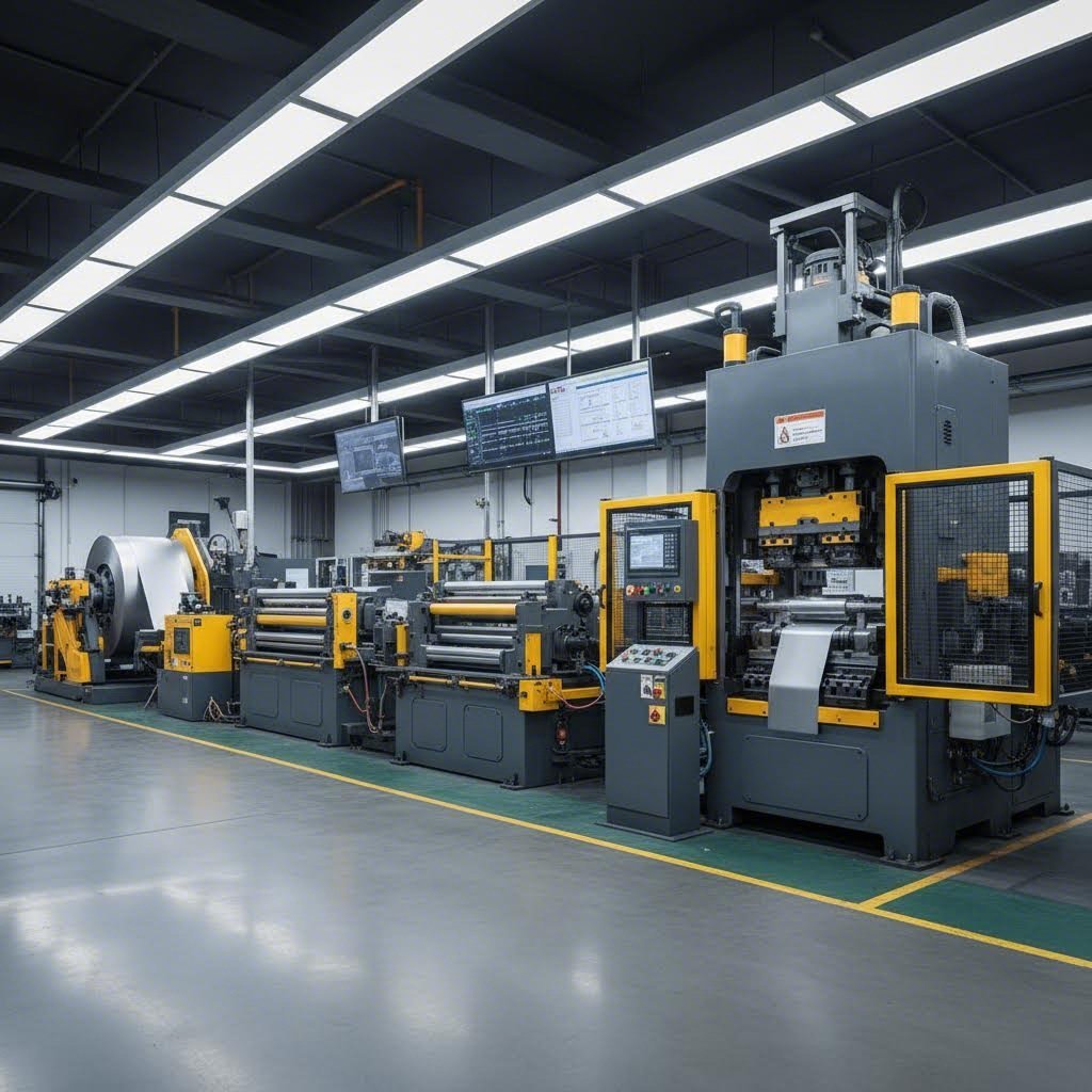
Представьте, что на ваше предприятие поступает рулон стали весом 10 000 фунтов. Как он превращается в тысячи прецизионных компонентов? Этот процесс включает несколько согласованных систем, работающих в идеальной синхронизации с вашим прессом для штамповки из рулона.
Согласно Анализ интеграции линии размотки рулона производителем , современные операции штамповки достигают максимальной эффективности, когда операторы могут управлять несколькими функциями с одного сенсорного экрана. Такая интеграция снижает количество ошибок и повышает эффективность, одновременно минимизируя занимаемую площадь на полу, количество источников питания и потребность в электропроводке.
Типичная установка пресса для штамповки из рулона включает:
- Разматыватель (барабан) - Удерживает рулон и подаёт материал с заданной скоростью. В передовых системах можно заранее подготовить несколько рулонов на одном оправочном валу; при расходовании одного рулона удерживающая рука автоматически выравнивает следующий.
- Выпрямитель - Устраняет кривизну материала (вызванную намоткой) с помощью серии рабочих валков. Встроенные системы управления автоматически корректируют положение валков на основе сохранённых параметров инструмента.
- Фидер - Подает материал точной длины в пресс при каждом ходе. Длина подачи, скорость и синхронизация точно согласованы с работой пресса.
- Контроль петли - Поддерживает петлю материала между правильным устройством и подающим механизмом, компенсируя колебания скорости подачи и предотвращая влияние натяжения на положение материала.
Основой любой интегрированной линии для рулонного материала является система управления. Большие цветные сенсорные экраны обеспечивают упрощённое управление предварительной подготовкой, производством, диагностикой и устранением неисправностей. Эти системы хранят предопределённые параметры производства для сотен штампов, используемых при настройке станка: угол подачи, скорость подачи, момент освобождения направляющих отверстий, высота оси подачи, положения направляющих для заготовки и настройки правильного устройства — всё это может автоматически восстанавливаться при смене задания.
Эта автоматизация значительно сокращает время переналадки. Вместо ручной настройки каждого компонента операторы вызывают сохранённые значения, и система настраивается самостоятельно. Ручной подход к вырубке на прессе — при котором операторы вручную протягивают материал и настраивают каждую станцию — по-прежнему применяется при изготовлении прототипов и малых партий, однако для крупносерийного производства требуется интегрированная автоматизация.
Интеграция операций пресса в производственные линии
Ваш вырубной пресс представляет собой лишь одну из станций в общем технологическом потоке производства. То, что происходит до и после штамповки, влияет на общую эффективность линии не меньше, чем сама операция на прессе.
Существуют два основных подхода к перемещению деталей в процессе штамповки:
Прогрессивная штамповка материал остаётся непрерывной лентой. Согласно Анализу процесса штамповки компании Keysight последовательные прессы выполняют последовательные операции на непрерывной металлической ленте внутри одного пресса. Несколько операций объединяются в одном комплекте штампов, что обеспечивает высокоскоростное производство с минимальным количеством манипуляций с деталями и отличной повторяемостью. Такой подход особенно эффективен для небольших деталей, таких как кронштейны и зажимы, выпускаемых большими объёмами.
Передача штамповки перемещает отдельные детали между станциями. В переносных прессах для продвижения деталей через несколько операций в пределах одной машины используются механические захваты, шагающие балки или роботизированные системы. Этот метод подходит для сложных деталей, требующих операций, которые невозможно выполнить, пока материал остаётся в виде ленты — например, глубокая вытяжка, которая в противном случае могла бы мешать соседним станциям.
Выбор между поточным производством и непрерывной штамповкой влияет на всё: от уровней запасов до трудозатрат:
- Серийная продукция - Запуск партий одного артикула, после чего переход на следующий. Эффективно при значительных временных затратах на переналадку по сравнению с длительностью цикла изготовления или когда операции последующих стадий не могут обеспечить темп, соответствующий скорости штамповки.
- Непрерывное производство - Специализированные линии, непрерывно выпускающие один артикул. Позволяют полностью исключить потери времени на переналадку, однако требуют достаточного объёма производства для экономически обоснованного выделения специализированного оборудования.
- Гибкие производственные ячейки - Инструменты быстрой замены и интегрированные системы управления обеспечивают быстрое переключение между артикулами, позволяя приближаться к уровню непрерывной эффективности при сохранении гибкости по размеру партий.
Операции последующих стадий подключены непосредственно к выходу пресса. Детали могут направляться на:
- Дополнительные операции формовки для получения элементов конструкции, которые невозможно изготовить в основной матрице
- Сварочные ячейки, где несколько штамповок соединяются в сборочные узлы
- Линии отделки (нанесение гальванических покрытий, окраска или нанесение других защитных покрытий)
- Сборочные станции, где штамповки становятся компонентами более крупных изделий
Интеграция контроля качества
Как вы можете быть уверены, что каждая деталь соответствует техническим требованиям, если её производится сотни штук в минуту? Современные штампы для прессования интегрируют контроль качества непосредственно в производственный процесс, а не полагаются исключительно на проверку после завершения операции.
Согласно анализу качества, проведённому компанией Eigen Engineering, точная металлоштамповка требует непрерывного контроля на всех этапах — а не только выборочного тестирования в отдельных зонах. Применение передовых решений для металлоштамповки на всём протяжении процесса обеспечивает стабильно высокое качество продукции.
Встроенные датчики в штамп обеспечивает мониторинг в реальном времени при каждом ходе пресса. Датчики фиксируют:
- Наличие детали и её правильное положение до начала цикла пресса
- Подтверждение выброса обрезков для предотвращения повторного удара
- Точность подачи материала, гарантирующую корректное продвижение заготовки
- Изменения усилия, указывающие на износ инструмента или изменение свойств материала
Эти системы детекторов внутри штампа защищают инструмент от случайного повреждения, вызванного обрезками, вариациями материала или неправильной подачей. В конце процесса датчики внутри штампа также проверяют соответствие изделия заданным параметрам до того, как детали покидают пресс.
Статистический контроль процесса (СПК) использует контрольные карты для отслеживания процесса штамповки в реальном времени. Для процесса устанавливаются допустимые диапазоны и критические параметры, а программное обеспечение статистического процессного контроля (SPC) автоматически фиксирует отклонения от заданных норм. Это помогает руководителям процессов выявлять соответствующие тенденции и внедрять решения до того, как условия выхода за пределы допусков приведут к браку.
Координатно-измерительные машины (CMM) обеспечивают точную размерную проверку в рамках самых жёстких производственных допусков. Данные координатно-измерительной машины (КИМ) поступают в системы статистического процессного контроля (SPC), что позволяет инженерам просматривать и анализировать контрольные карты в реальном времени и выявлять проблемы, требующие немедленного вмешательства.
Интеграция этих систем контроля качества позволяет выявлять проблемы немедленно — зачастую уже на первых нескольких бракованных деталях, а не после завершения всей партии. Когда оператор может устранять неполадки, стоя у пресса и просматривая диагностические данные на том же экране, который управляет производственным процессом, время реагирования сокращается с часов до секунд.
Понимание того, как ваш гидравлический пресс для штамповки металла вписывается в этот более широкий контекст производственных процессов, помогает принимать обоснованные решения при выборе оборудования, планировании компоновки линии и проектировании технологического процесса. После того как такая производственная перспектива определена, окончательным этапом остаётся выбор надёжного партнёра по поставке оборудования и оснастки, способного воплотить ваше производственное видение в жизнь.
Выбор подходящего партнёра по оборудованию и оснастке
Вы ознакомились с типами прессов, расчетами усилия, принципами проектирования штампов и интеграцией в рабочие процессы. Теперь наступает этап принятия решения, которое объединяет все эти аспекты: выбор правильного оборудования и надежного партнера для поставки оснастки. Это решение повлияет на ваши производственные возможности на годы — возможно, на десятилетия. Правильный выбор обеспечит стабильное качество продукции, надежные сроки поставки и партнерские отношения, основанные на сотрудничестве и позволяющие решать возникающие проблемы до того, как они достигнут вашего производственного участка. Ошибочный выбор? Задержки, дорогостоящая переделка и нарастающее разочарование с каждым новым заказом.
Оценка ваших производственных требований
Прежде чем обращаться к любому поставщику, необходимо чётко определить, какой именно результат вы стремитесь получить. Звучит очевидно? Вы удивитесь, сколько производителей пропускают этот этап и в итоге получают оборудование, не соответствующее их реальным потребностям.
Начните с объема производства. Вы изготавливаете прототипные партии — возможно, десятки или сотни деталей для испытаний и валидации? Или вам требуется высокопроизводительное производство, способное выпускать ежегодно тысячи или миллионы компонентов? Пресс для штамповки с диэлектрическим вырезом, оптимизированный для небольших партий, полностью отличается от пресса, предназначенного для непрерывного производства. Ваши требования к объему напрямую влияют на номинальное усилие пресса, уровень автоматизации и конструкцию оснастки.
Не менее важна сложность детали. Простые операции вырубки требуют прямолинейных комплектов штампов для металла. Для сложных деталей с множеством гибов, вытяжек и пробивных элементов необходимы прогрессивные или переносные штампы, требующие значительно больших инженерных затрат. Промышленный штамповочный станок для обработки простых форм стоит лишь небольшую долю стоимости сложной многостанционной оснастки.
Спецификации материалов вводят еще одну переменную. Гидравлический пресс и оснастка, разработанные для низкоуглеродистой стали, могут оказаться недостаточно эффективными при работе с нержавеющей сталью или алюминием. Для сталей повышенной прочности требуются совершенно иные подходы — от расчетной мощности пресса до зазоров в штампах. Согласно руководству по выбору производителя оснастки компании Die-Matic, одним из наиболее важных факторов при выборе производителя штамповки металла является его опыт работы с материалами, которые вы планируете использовать. Разные материалы требуют различного обращения, оснастки и технологических процессов.
Бюджетные ограничения влияют на всё. Однако самое низкое предложение редко соответствует наилучшей ценности. Металлорежущий штамп, цена которого на 20 % ниже рыночной, но который требует вдвое больших затрат на техническое обслуживание, обойдется дороже за весь срок службы. Аналогично, дешевая оснастка, требующая перезаточки каждые 50 000 циклов, обходится дороже, чем высококачественные штампы, способные работать 500 000 циклов между плановыми сервисными процедурами.
На что обратить внимание при выборе партнера по оснастке
Когда вы будете готовы оценить потенциальных поставщиков, выходите за рамки сравнения цен. Отношения, которые вы налаживаете, будут влиять на успех вашей производственной деятельности в течение многих лет. Вот ключевые вопросы, которые необходимо задать:
- Какими сертификатами они обладают? Для автомобильных применений обязательным является сертификат IATF 16949. Согласно обзору сертификаций Xometry, IATF 16949 — это система менеджмента качества, разработанная специально для производителей автомобильной продукции и направленная на обеспечение согласованности, безопасности и качества во всей автомобильной продукции. Хотя получение данного сертификата не является юридически обязательным, вы можете столкнуться с тем, что заказчики и поставщики отказываются сотрудничать с партнёрами, не имеющими соответствующей сертификации.
- Какую инженерную поддержку они предоставляют? Могут ли они оптимизировать конструкцию ваших деталей с учётом требований технологичности? Предоставляют ли они услуги по изготовлению прототипов и образцов для тестирования и доработки деталей до запуска их в серийное производство?
- Каким образом они используют технологии имитационного моделирования? Имитационное моделирование в CAE (инженерное проектирование с помощью компьютера) прогнозирует поведение материала при формовке, выявляет потенциальные дефекты и оптимизирует геометрию штампов до начала обработки стали. Это значительно снижает риски на этапе разработки.
- Каков их типичный срок изготовления прототипов по сравнению со сроком изготовления производственной оснастки? Возможность быстрого прототипирования — некоторые поставщики изготавливают прототипы всего за 5 дней — ускоряет ваш график разработки.
- Каков их показатель одобрения с первого предъявления? Этот показатель отражает, как часто штампы выпускают приемлемые детали при первом производственном запуске без необходимости доработки. Высокие значения (90 % и выше — это превосходный результат) свидетельствуют о надёжности инженерных процессов.
- Сколько лет они находятся на рынке и каков их показатель удержания клиентов? Клиенты, которые сотрудничают с компанией на протяжении длительного времени, подтверждают её надёжность и стабильность качества.
- Могут ли они масштабироваться в соответствии с вашими потребностями? Смогут ли они адаптироваться к увеличению — или снижению — ваших объёмов? Гибкость имеет ключевое значение для долгосрочного партнёрства.
- Какие процессы контроля качества применяются? Помимо сертификатов, уточните информацию об оборудовании для инспекции, методиках испытаний и системах прослеживаемости.
Несколько тревожных признаков должны насторожить вас при оценке потенциальных партнёров. Обратите внимание на нестабильное качество образцов деталей, слабую коммуникацию или медленные ответы, нежелание предоставить контакты существующих клиентов в качестве рекомендаций, а также отсутствие инвестиций в современное оборудование или технологии. Как правило, эти проблемы не решаются после подписания контракта.
Значение сертификации и моделирования
Сертификат IATF 16949 требует особого внимания для всех, кто работает в автомобильной промышленности. Этот стандарт выходит за рамки общих требований к системам менеджмента качества и охватывает специфические для автомобильной отрасли аспекты, включая:
- Аспекты безопасности продукции
- Системы предотвращения дефектов
- Снижение вариаций и потерь
- Фреймворки непрерывного улучшения
- Надёжную прослеживаемость на всех этапах производства
Сертификация — это не просто лист бумаги. Она отражает системный подход к обеспечению качества, который защищает ваши производственные сроки и вашу репутацию в глазах собственных клиентов. При оценке поставщика станков для металлической штамповки сертификация свидетельствует о том, что он инвестировал средства в процессы, минимизирующие ваши риски.
Имитационное моделирование с использованием CAE-программного обеспечения переводит разработку штампов из эмпирического метода «проб и ошибок» в предсказуемую инженерную задачу. До того как будет обработан хотя бы один миллиметр стали, программное обеспечение моделирует течение материала, прогнозирует упругое восстановление (springback), выявляет потенциальные зоны истончения или морщинистости и оптимизирует форму заготовки. Такая инвестиция на раннем этапе позволяет избежать дорогостоящих сюрпризов в ходе пробной наладки — традиционного этапа, когда новые штампы тестируются и корректируются для получения приемлемых деталей.
Сочетание надёжных систем обеспечения качества и передовых возможностей имитационного моделирования даёт измеримые результаты. Рассмотрим Решения Shaoyi в области прецизионных штамповочных матриц в качестве примера применения этих принципов. Их сертификация по стандарту IATF 16949 и передовые инженерные CAE-симуляции обеспечивают коэффициент одобрения с первого раза на уровне 93 % — то есть оснастка производит приемлемые детали при первой попытке более чем в девяти случаях из десяти. Возможность быстрого прототипирования всего за 5 дней значительно сокращает сроки разработки.
Эти показатели служат конкретными ориентирами при оценке любого поставщика. Задайте потенциальным партнёрам следующие вопросы: каков ваш коэффициент одобрения с первого раза? За какой срок вы можете поставить прототипы? Какие инструменты симуляции вы используете? Ответы, уступающие показателям лидеров отрасли, таких как Shaoyi, могут свидетельствовать о потенциальных пробелах в качестве или возможностях.
Принятие окончательного решения
После сбора информации как вы принимаете окончательное решение? Рассмотрите возможность создания взвешенной оценочной матрицы, в которой каждый потенциальный партнёр оценивается по вашим приоритетам. Для производителя штампов для металла, специализирующегося на автомобильных применениях, сертификация IATF может иметь высокий вес, тогда как поставщик, обслуживающий электронную промышленность, может отдавать предпочтение возможности обработки мелкого шага и соблюдению жёстких допусков.
Не стоит недооценивать ценность личных посещений производственных площадок. Личный осмотр объекта даёт гораздо больше информации, чем любой анкетный опрос. Организовано ли производственное помещение? Надлежащим образом ли обслуживается оборудование? Как сотрудники взаимодействуют друг с другом и с посетителями? Подобные наблюдения позволяют получить представление о корпоративной культуре и дисциплине операционной деятельности.
В заключение помните, что вы выбираете партнёра, а не просто поставщика. Наилучшие производственные отношения строятся на основе сотрудничества, совместного решения проблем и взаимных инвестиций в общий успех. Выбирайте поставщика, который проявляет подлинный интерес к пониманию ваших задач — а не того, кто предлагает самую низкую цену на оборудование для штамповки по вашим техническим требованиям.
Оборудование и оснастка для металлических штамповочных прессов, которые вы выберете сегодня, будут определять ваши производственные возможности на многие годы вперёд. Уделите достаточно времени тщательной оценке, задайте правильные вопросы и выберите партнёров, чьи компетенции и корпоративная культура соответствуют вашим целям долгосрочного успеха.
Часто задаваемые вопросы о металлических штамповочных прессах
1. - Посмотрите. Сколько стоит штамповка металла?
Стоимость штампов для листового металла обычно составляет от 500 до 15 000 долларов США в зависимости от сложности детали, типа штампа и требований к производству. Простые одноступенчатые штампы стоят дешевле, тогда как прогрессивные штампы с несколькими станциями имеют более высокую цену. Однако себестоимость одной детали зачастую значительно снижается по сравнению с методами обработки на станках с ЧПУ или ручной обработкой, что делает штампы экономически выгодным решением при объёмах свыше 500 штук. Сотрудничество с партнёрами, сертифицированными по стандарту IATF 16949, такими как Shaoyi, позволяет оптимизировать инвестиции в оснастку за счёт имитационного моделирования CAE, сокращающего количество итераций при разработке.
2. Для чего используется пресс-штамп?
Пресс-штамп преобразует плоские металлические листы в точные компоненты посредством операций резки, формовки, гибки и вытяжки. Машина создаёт контролируемое давление, зажимая металл между специализированными инструментами заданной формы, что приводит к необратимому изменению формы материала с получением деталей, таких как кузовные панели автомобилей, корпуса электронных устройств, кронштейны и компоненты бытовой техники. Штампы для металлической штамповки с острыми кромками выполняют резку и пробивку, тогда как формовочные штампы создают трёхмерные элементы за счёт пластической деформации металла.
3. Какие бывают типы штампов для прессов?
Существует четыре основных типа штампов для прессов: комбинированные штампы выполняют несколько операций одновременно за один ход; штампы с передачей деталей перемещают отдельные заготовки между станциями с помощью механических пальцев или роботизированных систем; прогрессивные штампы выполняют последовательные операции на непрерывной металлической ленте, которая продвигается через несколько станций; а штампы с одиночным вырубанием выполняют одну операцию за раз. Каждый тип подходит для разных объёмов производства, степени сложности деталей и производственных требований.
4. В чём разница между механическими и гидравлическими штамповочными прессами?
Механические прессы используют системы с маховиком для высокоскоростного производства и достигают максимального усилия (в тоннах) вблизи нижней точки хода. Они отлично подходят для операций с прогрессивными штампами и высокопроизводительной штамповки. Гидравлические прессы создают усилие за счёт давления жидкости и обеспечивают полное номинальное усилие (в тоннах) в любой точке хода. Это делает их идеальными для глубокой вытяжки, сложной формовки и операций, требующих выдержки под нагрузкой. Сервопрессы сочетают в себе высокую скорость механических прессов с программируемой гибкостью и позволяют задавать переменные профили хода для трудных операций формовки.
5. Как рассчитать требуемое усилие (в тоннах) для металлического штамповочного пресса?
Рассчитайте тоннаж по этой формуле: периметр (мм) × толщина (мм) × сопротивление срезу (кгс/мм²) × коэффициент запаса прочности (1,1–1,2) ÷ 1000. Ключевыми факторами являются длина периметра реза, толщина материала, сопротивление срезу (примерно 60 % от предела прочности при растяжении) и зазор между пуансоном и матрицей. Для сталей повышенной прочности требуется тщательный расчёт, поскольку традиционные методы зачастую дают заниженные оценки требуемых значений. Имитационное моделирование в CAE обеспечивает более точные прогнозы за счёт построения кривых усилия на всём протяжении хода.