 Serii mici, standarde ridicate. Serviciul nostru de prototipare rapidă face validarea mai rapidă și mai ușoară —

Decodificarea matrițelor de fabricație: de la selecția oțelului până la stăpânirea producției
Ce este o matriță de fabricație și de ce este importantă
V-ați întrebat vreodată cum produc constructorii auto milioane de panouri identice pentru uși sau cum creează producătorii de echipamente electronice carcase metalice perfect uniforme? Răspunsul se află într-un instrument specializat de precizie care stă la baza producției moderne: matrița de fabricație. Înțelegerea conceptului de matriță în fabricație deschide calea spre aprecierea modului în care producția de masă obține o consistență remarcabilă în numeroase industrii.
Fundamentul producției de masă
O matriță de fabricație este un instrument specializat pentru mașini, conceput pentru a tăia, modela sau forma materiale — în principal tablă subțire — în configurații precise, prin aplicarea unei forțe mecanice. Gândiți-vă la ea ca la un șablon master care transformă materialele brute în componente finite, cu o repetabilitate exactă. Spre deosebire de metodele de producție manuală, o matriță este utilizată pentru a produce mii sau chiar milioane de piese identice, fără nicio variație.
Deci, la ce se folosește exact o matriță? Aceste unelte de precizie reprezintă baza industriei care necesită o calitate constantă a pieselor, la scară largă. De la panourile de caroserie auto până la carcasele electronice, de la componente aero-spațiale până la electrocasnice, matrițele permit producătorilor să obțină:
- Precizie dimensională: Piese fabricate în limite de toleranță de ordinul micronilor pe întreaga serie de producție
- Viteza de producție: Timpuri de ciclu măsurați în secunde, nu în minute sau ore
- Eficiență Costurilor: Costuri mai mici pe unitate pe măsură ce volumele de producție cresc
- Consistență calitate: Piese practic identice, de la prima piesă până la milionul de piese
De la materialul brut la piesa de precizie
Mecanica de bază a modului în care o matriță interacționează cu materialele piesei prelucrate implică un principiu simplu, dar elegant. Atunci când este montată într-o presă, setul de matrițe — format din componente superioare și inferioare — aplică o forță controlată asupra tablei metalice poziționate între ele. Această forță determină deformarea plastică a materialului, care ia forma exactă definită de cavitatea matriței.
În timpul unei operații tipice de ambutisare, următoarele evenimente au loc în milisecunde:
- Ramul de presă coboară, aducând poansonul (componenta superioară a matriței) către semifabricat
- Materialul din tablă metalică intră în contact cu blocul de matriță (componenta inferioară) și începe să se deformeze
- Forța aplicată depășește limita de curgere a materialului, provocând o schimbare permanentă de formă
- Ramul se retrage și piesa finită este ejectată — gata pentru următorul ciclu
Un punct frecvent de confuzie îl reprezintă diferențierea dintre matrițe și forme. Deși ambele sunt unelte de modelare, ele funcționează pe principii fundamental diferite. O matriță lucrează, de obicei, cu tablă metalică solidă și aplică forță mecanică pentru tăierea sau deformarea materialului. În schimb, formele lucrează cu materiale lichide sau topite — cum ar fi plasticul sau metalele turnate — care se solidifică într-o cavitate. Conform prezentării tehnice ale LeadRP, această distincție este esențială: „O formă este utilizată pentru modelarea materialelor prin solidificarea acestora în interiorul formei, în timp ce o matriță este utilizată pentru tăierea sau modelarea materialelor prin aplicarea unei forțe mecanice.”
Această diferență fundamentală explică de ce fabricarea matrițelor necesită o atenție excepțională acordată durității materialelor, rezistenței la uzură și ingineriei de precizie. Fiecare lovitură a presei supune matrița unor forțe enorme, iar menținerea preciziei pe parcursul a milioane de cicluri necesită o metalurgie sofisticată și toleranțe extrem de stricte, pe care le vom analiza în detaliu în cadrul acestui ghid.
Tipuri de matrițe utilizate în fabricație – explicații
Acum că ați înțeles ce rol îndeplinește o matriță în procesul de fabricație, următoarea întrebare logică este: ce tip de matriță se potrivește nevoilor dumneavoastră de producție? Răspunsul depinde de complexitatea pieselor, volumul de producție și cerințele operaționale. Să analizăm principalele categorii și să vă ajutăm să luați această decizie esențială.
Matrițe pentru ambutisare și tăiere
Matrițele pentru tăiere reprezintă probabil categoria cea mai fundamentală în operațiunile de ambutisare a metalelor. Conform Fabricantul , tăierea este operația cea mai frecventă pe care o efectuează o matriță de ambutisare. Când un ciocan de matriță coboară prin presa de matrițe, materialul din foaie de metal, așezat între două componente ale matriței, este secționat în momentul în care muchiile de tăiere se deplasează una față de cealaltă cu o joc exact.
Operațiile principale de tăiere includ:
- Decupare: Tăierea formei dorite a piesei din foaia de metal, unde piesa îndepărtată devine semifabricatul
- Perforare: Crearea de găuri sau deschideri, unde materialul îndepărtat devine deșeu
- Nivelarea: Îndepărtarea materialului de pe marginea unei benzi sau a unui semifabricat
- Tăiere: Îndepărtarea materialului în exces de pe o piesă deja formată anterior
- Tăiere prin forfecare: Tăierea în linie dreaptă de-a lungul lungimii materialului
Jocul de tăiere — micul spațiu dintre ciocanul și blocul matriței — variază în funcție de proprietățile materialului și de starea dorită a marginii . Majoritatea operațiilor de tăiere supun metalul la efort până la punctul său de rupere, generând o margine caracteristică, cu o bandă lucioasă de tăiere și o zonă de rupere mai aspră.
Matrițe pentru deformare și tragere
În timp ce matrițele de tăiere îndepărtează materialul, matrițele de deformare îl reconfigurează fără separare. Aceste unelte aplică o forță controlată pentru a îndoi, întinde sau comprima tabla metalică în configurații tridimensionale. Înțelegerea fiecărui tip vă ajută să alegeți matrița potrivită pentru aplicațiile la prese, în funcție de cerințele specifice.
Matrice de încovoiere deformează metalul de-a lungul unei axe drepte, creând niște proeminențe (tabs), canale și elemente unghiulare. Această operație simplă de deformare apare într-o mulțime de componente, de la suporturi până la carcase.
Stăpânirea decalajelor reprezintă unele dintre cele mai impresionante unelte de deformare din domeniul fabricației. Conform explicațiilor publicației The Fabricator, matrițele de tragere creează formele pieselor prin controlul curgerii metalului într-o cavitate, folosind dispozitive de fixare a semifabricatelor încărcate cu presiune. Gândiți-vă la ușile de automobile, la capacele de ulei, la vasele de bucătărie și la mânerele de ușă — toate sunt produse prin operații de tragere.
Matrițe pentru ambutisare prin clincuire modelează piesele prin comprimarea metalului sub presiune extremă, reducând adesea grosimea acestuia, dar imprimând în același timp caracteristici precise ale suprafeței. Moneda metalică constituie exemplul clasic al acestui proces.
Operațiunile suplimentare de deformare includ:
- Întinderea: Crearea de imprimeuri prin reducerea grosimii metalului, nu prin tragerea materialului spre interior
- Flanșare: Îndoirea metalului de-a lungul unor axe curbe, generând flanșe supuse fie la întindere, fie la compresiune
- Extrudarea: Deformarea profilurilor radiale continue în jurul găurilor preforate
- Aplicarea cu ferul: Uniformizarea grosimii pereților în timp ce se mărește lungimea vasului obținut prin tragere
Comparare completă a tipurilor de matrițe
Selectarea configurației potrivite de matriță pentru ambutisare necesită echilibrarea mai multor factori. Tabelul de mai jos oferă o comparație pe colțuri pentru a vă ghida în luarea deciziei:
| Tip die | Funcția principală | Materialele tipice procesate | Conformitate cu volumul de producție | Nivel de complexitate |
|---|---|---|---|---|
| Matrice de decupaj | Taie forme plane din foi | Oțel, aluminiu, cupru, alamă | Volum scăzut până la ridicat | Scăzut până la mediu |
| Matriță de perforare | Creează găuri și deschideri | Majoritatea tablelor metalice | Volum scăzut până la ridicat | Scăzute |
| Matrita de îndoire | Formează caracteristici unghiulare | Oțel, aluminiu, inox | Volum scăzut spre mediu | Scăzut până la mediu |
| Matriței de tragere | Creează forme 3D adânci | Tragere adâncă din oțel și aluminiu | Volum mediu spre mare | Ridicat |
| Matriță de coining | Formare precisă a suprafețelor | Metale mai moi, oțel | Volum mediu spre mare | Mediu la ridicat |
| Matrice progresivă | Operații multiple în secvență | Metale sub formă de bandă continuă | Volum Înalt | Ridicat |
| Matriță de transfer | Formare complexă în stații multiple | Diverse metale sub formă de foaie | Volum mediu spre mare | Foarte sus |
| Fracțiune compusă | Operații simultane de tăiere | Foi plane din metal | Volum scăzut spre mediu | Mediu |
Matrice progresive vs. matrice cu transfer vs. matrice compuse: Diferențele esențiale
Alegerea între matricele progresive, cele cu transfer și cele compuse reprezintă adesea cea mai importantă decizie privind dotarea tehnică cu care se confruntă producătorii. Fiecare abordare oferă avantaje distincte, în funcție de aplicația specifică.
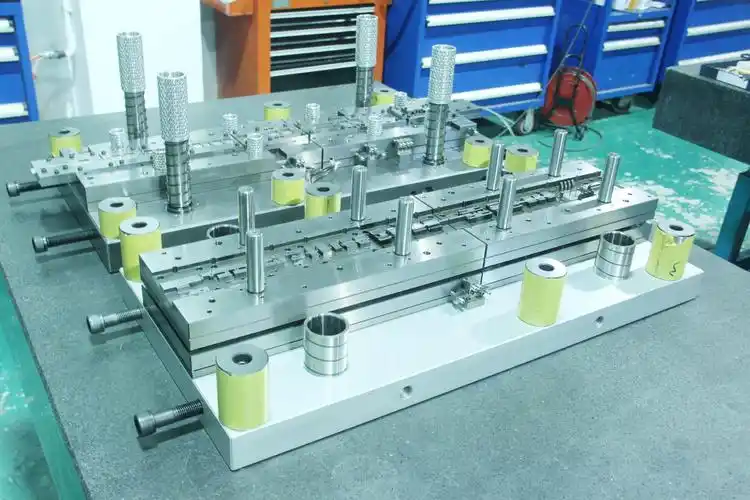
Matrițe progresive montează toate stațiile necesare de tăiere și deformare pe un singur set comun de matrițe. Pe măsură ce banda avansează prin presă, fiecare stație efectuează operația sa specificată, în ordine secvențială. Conform Worthy Hardware, tanțarea cu matrițe progresive se remarcă prin viteza ridicată de producție, fiind ideală pentru serii mari. Partea finită rămâne conectată la banda purtătoare pe tot parcursul procesului, până la separarea finală.
Caracteristici cheie ale matrițelor de tanțare progresivă:
- Cele mai mari viteze de producție dintre metodele cu mai multe operații
- Costuri mai mici pe piesă la volume mari, în ciuda investiției inițiale semnificative în dotări
- Potrivite în special pentru piese mai mici și mai puțin complexe
- Necesită material alimentat sub formă de bandă, cu lățime constantă
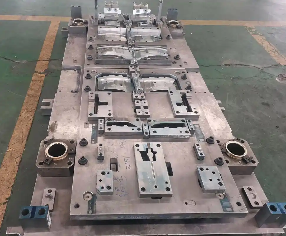
Transferul ștanțelor funcționează în mod diferit — piesele individuale se deplasează între stații separate prin șine mecanice sau degete montate în interiorul presei. Această metodă este excelentă atunci când se prelucrează geometrii mai mari și mai complexe, care ar fi imposibil de realizat în configurații progresive. Fabricatorul subliniază faptul că matrițele de transfer sunt matrițe de linie sincronizate și amplasate la distanțe egale, iar piesele sunt transferate prin intermediul șinelor mobile.
Avantajele matrițelor de transfer includ:
- Flexibilitate crescută pentru designuri intricate și orientări variabile ale pieselor
- Capacitatea de a produce piese mai mari decât cele permise de matrițele progresive
- Potrivirea atât pentru serii scurte, cât și pentru serii lungi de producție
- Posibilitatea de a integra operații precum perforarea, îndoirea, tragerea și tăierea într-un singur ciclu
Totuși, operațiunile de transfer implică, de obicei, timpi mai lungi de configurare și costuri operaționale mai mari datorită complexității sporite și necesității unui personal calificat.
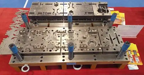
Compound dies efectueze mai multe operații de tăiere simultan, într-o singură cursă a presei. Spre deosebire de matrițele progresive, care efectuează operațiile în mod secvențial, pe stații diferite, matrițele compuse execută decuparea și perforarea în același moment. Această abordare funcționează excepțional de bine pentru piese mai simple, plane, care necesită o precizie ridicată.
Când ar trebui să alegeți matrițe compuse?
- Piesele necesită doar operații de tăiere, fără deformare
- Planeitatea și concentricitatea sunt cerințe critice de calitate
- Volumele de producție sunt mici sau medii
- Geometria piesei este relativ simplă
Conform explicațiilor oferite de Standard Die, matrițele compuse efectuează simultan numeroase operații, ceea ce face proiectele mai eficiente și mai rapide — deși nu sunt recomandate pentru operațiile de deformare și îndoire, deoarece acestea necesită adesea o forță mai mare.
Înțelegerea acestor diferențe vă pune într-o poziție favorabilă pentru a lua decizii informate privind dotarea cu scule. Totuși, alegerea tipului potrivit de matriță reprezintă doar o parte a ecuației — procesul de fabricație care dă viață acestor scule de precizie merită o atenție egală.
Procesul complet de fabricație a matrițelor
V-ați întrebat vreodată cum se transformă un bloc grosolan de oțel într-un instrument de precizie capabil să producă milioane de piese identice? Procesul de realizare a matrițelor implică o succesiune bine coordonată de operații specializate — fiecare etapă construindu-se pe cea precedentă. Înțelegerea modului de realizare a unei matrițe, de la concept până la finalizare, evidențiază motivul pentru care acest proces necesită o astfel de expertiză, investiții semnificative și o atenție deosebită la detalii.
Elaborarea planului de inginerie
Fiecare matriță excepțională începe nu pe terenul de producție, ci în domeniul digital. Producția modernă de matrițe pornește cu proiectarea și simularea completă — o fază care determină aproximativ 80 % din succesul sau eșecul final al sculei.
Procesul de proiectare se desfășoară în mai multe etape esențiale:
- Analiza piesei și studiul de fezabilitate: Inginerii evaluează geometria componentei, specificațiile materialelor și cerințele privind volumul de producție, pentru a determina configurația optimă a matriței
- Proiectarea conceptuală a matriței: Folosind un software avansat de proiectare asistată de calculator (CAD), designerii dezvoltă structura matriței, inclusiv liniile de separare, geometria poansonului și a blocului de matriță, precum și aranjamentul componentelor
- Simulare și validare CAE: Analiza cu element finit (FEA) și simulările de deformare previzionează modul în care materialele se vor comporta în condiții reale de producție
Aici este locul unde fabricarea modernă a matrițelor se distinge cu adevărat de abordările tradiționale. Conform experților din domeniu de la Jeelix, simularea prin calcul asistat de inginerie (CAE) acționează ca o „bilă de cristal”, dezvăluind exact cum se va comporta o matriță în condiții reale de funcționare — mult înainte ca prima bucată de oțel să fie tăiată. Această capacitate predictivă identifică defectele potențiale, inclusiv:
- Subțierea materialului și zonele cu risc de fisurare
- Revenirea elastică care ar putea afecta precizia dimensională
- Îndoirea (încrețirea) în operațiunile de tragere
- Concentrările de tensiune care ar putea duce la cedarea prematură a matriței
Prin detectarea acestor probleme în mod virtual, producătorii evită iterațiile fizice costisitoare care necesitau anterior mai multe cicluri de încercare și eroare. Rezultatul? Termene de dezvoltare comprimate, costuri reduse pentru prototipare și matrițe care ating stadiul pregătit pentru producție mai rapid .
De la blocul de oțel la scula de precizie
Odată ce proiectarea este aprobată de ingineri, începe transformarea fizică. Procesul de realizare a matriței urmează o succesiune bine definită, în care fiecare operațiune pregătește semifabricatul pentru următorul nivel de precizie.
Selecția și pregătirea materialelor
Alegerea oțelului potrivit pentru matrițe reprezintă o decizie strategică care echilibrează duritatea, tenacitatea, rezistența la uzură și costul. Printre selecțiile frecvente se numără oțelul D2 pentru aplicațiile cu uzură intensă, oțelul A2 pentru proprietăți echilibrate și oțelul H13 pentru operațiunile de prelucrare la cald. Vom analiza în detaliu aceste opțiuni în secțiunea următoare.
Înainte de începerea oricărei prelucrări, blocurile brute de oțel sunt supuse unei etape de pregătire pentru a stabili suprafețe de referință stabile. Această lucrare de bază asigură faptul că toate operațiunile ulterioare păstrează alinierea corectă și precizia dimensională.
Operațiuni de prelucrare grosolană
Frezarea cu comandă numerică (CNC) constituie metoda principală utilizată în prelucrarea matrițelor, realizând 70–80% din volumul total de material eliminat, conform Ghidului complet al Jeelix . În această fază, operatorii prelucrează matrița pentru a obține geometria de bază, eliminând materialul în exces, dar lăsând un adaos calculat pentru operațiunile finale de finisare.
Mașinile moderne CNC cu 3 axe și 5 axe execută trasee complexe ale sculelor cu o eficiență remarcabilă. Totuși, prelucrarea grosolană se oprește intenționat înainte de atingerea dimensiunilor finale — lăsând, în mod tipic, un adaos de 0,5–1,0 mm de material pentru operațiunile ulterioare de precizie.
Tratarea termică: Transformarea critică
Tratamentul termic reprezintă una dintre cele mai cruciale etape în fabricarea matrițelor și a sculelor. Această prelucrare termică transformă fundamental microstructura oțelului, convertind un material relativ moale într-un oțel durificat, capabil să reziste milioane de cicluri de producție.
Procesul implică, de obicei, două faze esențiale:
- Calirea: Încălzirea oțelului până la temperatura de austenitizare (800–1050 °C, în funcție de calitate) urmată de răcirea rapidă forțează structura cristalină să se transforme într-o fază extrem de dură, dar fragilă, numită martensită. Aceasta creează baza durității.
- Înălțimea: După călire, oțelul conține tensiuni interne foarte mari. Reîncălzirea la 150–650 °C eliberează aceste tensiuni și reduce fragilitatea — un schimb deliberat al unei părți din duritate în favoarea unei tenacități îmbunătățite. Acest lucru previne fisurarea catastrofală în timpul utilizării în producție.
Rețeta specifică de tratament termic variază în funcție de calitatea oțelului pentru matrițe și de aplicația prevăzută. Efectuarea greșită a acestei etape poate face inutilizabile componente prelucrate costisitoare — sau, mai rău, poate duce la obținerea unor matrițe care cedează neașteptat în timpul producției.
Fieruire cu Precizie
După tratamentul termic, componentele matrițelor necesită rectificare de precizie pentru a atinge exactitatea dimensională finală. Roțile de rectificare de înaltă viteză efectuează tăierea fină a suprafețelor pieselor prelucrate, constituind ultimul gardian al preciziei geometrice.
Rectificatoarele plane asigură specificațiile de planitate măsurate în microni, în timp ce rectificatoarele cilindrice perfectează diametrele găurilor și suprafețele exterioare. Această etapă elimină distorsiunile cauzate de tratamentul termic, care apar inevitabil în timpul procesării termice.
Operațiuni EDM: Accesul la zonele inaccesibile
Atunci când sculele de așchiere rotative nu pot accesa fizic anumite caracteristici, prelucrarea prin descărcare electrică (EDM) ia sub conducere. Această tehnologie folosește scântei electrice controlate pentru a eroda materialul cu o precizie excepțională.
Prelucrarea prin electroeroziune cu fir folosește un electrod din fir de alamă (de obicei cu diametrul de 0,1–0,3 mm) pentru a tăia profile extrem de precise în piesele prelucrate din materiale durificate. Conform observațiilor Jeelix, electroeroziunea cu fir este «microchirurgul» familiei EDM — capabilă să realizeze toleranțe pe care metodele convenționale de prelucrare prin matrițare nu le pot atinge deloc.
Electroeroziunea cu electrod masiv (cunoscută și sub denumirea de electroeroziune cu ramă) creează cavități complexe tridimensionale prin imersarea electrodului profilat în piesa prelucrată. Acest proces se remarcă prin capacitatea sa de a produce detalii intricate, cum ar fi colțurile interne ascuțite și contururile complexe, care nu ar putea fi realizate direct prin frezare.
Asamblare și ajustare
După ce toate componentele sunt prelucrate conform specificațiilor, asamblarea adună piesele din oțel rece într-un sistem coerent. Această fază implică mult mai mult decât simpla fixare a pieselor cu șuruburi.
Montajul calificat al matrițelor presupune efectuarea unei lucrări minuțioase de „verificare punctuală” — utilizând compuși de marcare pentru a verifica modelele de contact dintre suprafețele în contact. Aceștia reglează jocurile, verifică alinierea și se asigură că toate componentele mobile funcționează fără probleme. Această măiestrie practică rămâne esențială chiar și în mediile de producție extrem de automate.
Încercare și validare
Încercarea inițială cu matrița finalizată (FOT) reprezintă examinarea finală a matriței. Inginerii montează matrița finalizată pe o presă și produc piese eșantion inițiale. Aceste eșantioane sunt supuse unei inspecții riguroase pentru a verifica:
- Precizia dimensională față de specificațiile de proiectare
- Calitatea suprafeței și aspectul
- Modelele de curgere a materialului în operațiunile de deformare
- Funcționarea și indicatorii de durabilitate ai matriței
Încercările inițiale rareori produc rezultate perfecte. Inginerii analizează eventualele abateri, diagnostichează cauzele fundamentale și aplică corecțiile necesare. Încercările ulterioare (T1, T2 și altele) îmbunătățesc progresiv performanța până când matrița produce în mod constant piese care îndeplinesc toate cerințele.
Această secvență completă de fabricare a matrițelor — de la proiectarea digitală până la dotarea de producție validată — durează în mod obișnuit săptămâni sau luni, în funcție de complexitate. Totuși, această investiție aduce beneficii pe parcursul a milioane de cicluri de producție. Odată ce procesul de fabricare este înțeles, alegerea oțelului potrivit pentru matriță devine următoarea decizie critică.
Selectarea materialului pentru matriță și proprietățile oțelului
Ați proiectat geometria perfectă a matriței și ați stabilit procesul de fabricare. Dar iată o întrebare care poate determina succesul sau eșecul investiției dumneavoastră în dotări: care material din oțel pentru matriță va rezista, de fapt, milioanelor de cicluri de producție? Alegerea unui oțel nepotrivit pentru matriță este ca și cum ați alege pantofi de drumeție pentru un maraton — tehnic, sunt încălțăminte, dar fundamental nepotrivită pentru sarcina respectivă.
Selectarea oțelului pentru matrițe nu este o presupunere. Este o decizie strategică care echilibrează proprietățile materialelor concurente în funcție de cerințele specifice ale producției dumneavoastră. Înțelegerea acestor compromisuri distinge între utilajele care funcționează în mod fiabil și eșecurile costisitoare care stau inactiv pe podeaua atelierului.
Potrivirea proprietăților oțelului cu cerințele aplicației
Fiecare aplicație a unei matrițe prezintă o combinație unică de provocări. O matriță metalică pentru ambutisarea aluminiului subțire diferă în mod semnificativ de una utilizată pentru perforarea oțelului inoxidabil durificat. Înainte de a analiza gradele specifice, luați în considerare întrebările cheie care ar trebui să vă ghideze selecția:
- Ce material prelucrați? Materialele mai dure ale pieselor de prelucrat necesită oțeluri pentru matrițe mai dure și mai rezistente la uzură
- Ce operații va efectua matrița? Operațiile de tăiere solicită marginile într-un mod diferit față de operațiile de deformare, care absorb șocul
- Ce volum de producție aveți nevoie? Volumele mai mari de producție justifică utilizarea unor oțeluri premium pentru matrițe, cu o durabilitate superioară
- Ce toleranțe trebuie să mențineți? Specificațiile mai stricte necesită oțeluri cu o stabilitate dimensională excelentă
- Care este mediul dumneavoastră de operare? Aplicațiile la temperaturi înalte necesită oțeluri care își păstrează proprietățile la temperaturi ridicate
Conform ghidului pentru oțeluri pentru scule al Ryerson, mărcile obișnuite, inclusiv A2, D2, O1, S7, H13 și M2, sunt esențiale în producția uneltelor de bază și a matrițelor pentru mașini. Fiecare dintre acestea oferă caracteristici distincte, potrivite unor aplicații specifice.
Compromisuri între duritate, tenacitate și rezistență la uzură
Imaginați-vă că vă echilibrați pe un scaun cu trei picioare. Înclinați-vă prea mult spre oricare dintre cele trei proprietăți, și întregul sistem se răstoarnă. Alegerea oțelurilor pentru matrițe funcționează în mod similar: optimizarea unei caracteristici implică adesea compromiterea alteia.
Duritate măsoară rezistența oțelului la indentare și deformare. O duritate mai mare se corelează, de obicei, cu o rezistență superioară la uzură — esențială pentru componentele matrițelor care trebuie să mențină muchii ascuțite de tăiere pe parcursul unor serii lungi de producție. Totuși, oțelurile extrem de dure devin fragile și susceptibile la spargere sau fisurare sub acțiunea unor șocuri.
Rezistență reprezintă capacitatea oțelului de a absorbi energie fără a se rupe. Aplicațiile care necesită rezistență la șoc — în care matrițele sunt supuse unor impacturi bruște sau vibrații — cer o tenacitate mai ridicată, chiar dacă acest lucru implică sacrificarea unei părți din duritate. O matriță care se sparge la fiecare a treia cursă este inutilizabilă, indiferent de valoarea sa de duritate.
Rezistenta la uzura determină cât de bine păstrează suprafețele geometria lor inițială în ciuda frecării continue și a uzurării prin abraziune. Manualul Alro Steel pentru Matrițe și Unelte furnizează tabele comparative cuprinzătoare care arată că oțelurile din seria D, cum ar fi D2 și D3, oferă o rezistență la uzură prin abraziune semnificativ mai mare decât gradele rezistente la șoc din seria S — dar cu valori corespunzătoare mai scăzute de tenacitate.
Iată realitatea practică: oțelurile mai dure rezistă la uzură, dar pot crăpa sub sarcini de impact. Oțelurile mai moi și mai tenace absorb șocul, dar se uzează mai rapid. Sarcina dumneavoastră este să găsiți punctul optim pentru aplicația specifică pe care o aveți în vedere.
Comparație obișnuită a oțelurilor pentru matrițe
Tabelul următor compară cele mai utilizate oțeluri pentru matrițe, ajutându-vă să potriviți proprietățile materialelor cu cerințele de producție:
| Calitatea oțelului | Gamă de duritate (HRC) | Caracteristici principale | Cele mai bune aplicații | Cost relativ |
|---|---|---|---|---|
| D2 | 58-62 | Rezistență extrem de ridicată la uzură; stabilitate excelentă a dimensiunilor în timpul tratamentului termic; călire profundă în aer | Matrițe pentru decupare în volum mare; matrițe de ambutisare pentru materiale abrazive; tăietoare; poansoane; matrițe de finisare | Mediu-Mare |
| A2 | 57-62 | Combinație bună între rezistența la uzură și tenacitate; foarte stabil în timpul tratamentului termic; călire în aer | Matrițe pentru decupare și deformare; poansoane; calibre; componente ale matrițelor care necesită un echilibru între proprietăți | Mediu |
| S7 | 54-58 | Rezistență excelentă la șoc; rezistență bună la uzură; util pentru lucrul la rece și la temperaturi moderate înaltă | Unelte de impact; matrițe de deformare; cavitați pentru matrițe de injectare plastic; aplicații supuse încărcărilor repetitive de șoc | Mediu |
| H13 | 44-52 | Duritate ridicată la temperaturi înalte; rezistență excelentă la oboseală termică; tenacitate bună la temperaturi ridicate | Matrițe pentru turnare sub presiune; matrițe pentru forjare la cald; scule pentru extrudare; aplicații la cald cu răcire cu apă | Mediu |
| M2 | 62-65 | Duritate roșie foarte ridicată; rezistență excepțională la uzură; menține duritatea la temperaturi înalte | Scule de așchiere de mare viteză; poansoane pentru materiale dure; inserții pentru matrițe care necesită o rezistență extremă la uzură | Ridicat |
Oțeluri călibrabil prin răcire în aer vs. oțeluri călibrabil prin răcire în ulei
Metoda de călire influențează în mod semnificativ performanța matrițelor, distorsiunea și complexitatea fabricației. Înțelegerea acestei diferențe vă ajută să alegeți materialele potrivite pentru componentele matrițelor dumneavoastră.
Oțeluri călibrabil prin răcire în aer precum A2, se răcesc lent în aer staționar după încălzire, transformându-se în starea lor călită fără a necesita o călire în lichid. Conform manualului Alro, A2 oferă „o combinație bună între rezistența la uzură și tenacitate”, fiind „foarte stabil în tratamentul termic.”
Avantajele calibrării în aer includ:
- Distorsiune minimă: Răcirea mai lentă și mai uniformă reduce deformarea și modificările dimensionale
- Risc redus de fisurare: Şoc termic mai mic comparativ cu răcirea rapidă
- Prelucrare mai ușoară: Nu este necesară utilizarea vaselor de răcire sau gestionarea uleiului
- Stabilitate dimensională superioară: Rezultate dimensionale mai previzibile după tratamentul termic
Când ar trebui să alegeți oțelul A2 în locul alternativelor? Luați în considerare oțelurile care se întăresc în aer atunci când produceți componente pentru matrițe fără acoperire, cu geometrii complexe, secțiuni subțiri sau cerințe stricte de toleranță, unde deformarea ar putea constitui o problemă.
Oțeluri care se întăresc în ulei cum ar fi O1, necesită o răcire rapidă în ulei încălzit pentru a obține duritatea maximă. Deși oferă o prelucrabilitate excelentă în starea recoptă și o retenție bună a muchiei, aceste calități prezintă un risc mai mare de deformare în timpul tratamentului termic. Conform datelor furnizate de Alro, oțelul O1 are un indice de prelucrabilitate de 90 % comparativ cu oțelul carbon standard — ceea ce face ca prelucrarea sa să fie mai ușoară, dar potențial mai dificilă în ceea ce privește tratamentul termic fără apariția unor probleme dimensionale.
Compromisul este simplu: oțelurile care se călesc în ulei sunt adesea mai ieftine și se prelucrează mai ușor, dar necesită o tratare termică mai atentă pentru a evita deformarea. Pentru aplicațiile plăcilor de presiune care necesită o planitate excepțională, calitățile care se călesc în aer se dovedesc, de obicei, mai fiabile.
Inserturi din carburi: Când oțelurile standard nu sunt suficiente
Uneori, chiar și cele mai bune oțeluri pentru matrițe nu pot rezista solicitărilor extreme. Materialele extrem de abrazive, volumele de producție ultra-mari sau cerințele stricte de toleranță pot impune utilizarea inserturilor din carburi de wolfram în zonele supuse unei uzuri intense.
Carburile oferă niveluri de duritate (HRA 89–93) mult mai mari decât orice matriță realizată din oțeluri convenționale pentru scule. Această duritate extremă se traduce printr-o durată de viață semnificativ extinsă în aplicațiile în care oțelurile standard s-ar uza nesuportabil de rapid.
Totuși, utilizarea carburilor implică considerente semnificative:
Avantajele inserturilor din carburi
- Rezistență excepțională la uzură — adesea o durată de viață de 10–20 ori mai lungă decât cea a oțelurilor pentru scule
- Mențin muchiile ascuțite de tăiere mult mai mult timp
- Finisare excelentă a suprafeței pieselor stampilate
- Reduce timpul de nefuncționare pentru întreținerea și ascuțirea matrițelor
Dezavantajele inserțiilor din carburi
- Cost inițial semnificativ mai ridicat (de 3–5 ori mai mare decât cel al oțelurilor pentru matrițe)
- Natura fragilă necesită o proiectare atentă a matriței pentru a preveni încărcarea bruscă
- Mai complexe de prelucrat și de montat în ansamblurile de matrițe
- Nu pot fi sudate sau reparate ușor în cazul deteriorării
Calculul cost-beneficiu favorizează utilizarea carburiilor atunci când volumele de producție sunt suficient de mari pentru a amortiza costul suplimentar, atunci când materialele pieselor prelucrate sunt extrem de abrazive sau atunci când toleranțele sunt atât de strânse încât orice uzură a matriței devine inacceptabilă. Pentru volume mai mici de producție sau aplicații mai puțin exigente, oțelurile superioare pentru matrițe, cum ar fi D2 sau M2, oferă adesea performanțe adecvate la un investiție inițială mai redusă.
Alegerea dvs.
Alegerea oțelului pentru matriță potrivit aplicației dvs. necesită o evaluare obiectivă a priorităților dvs. Luați în considerare acest cadru decizional:
- Pentru rezistență maximă la uzură în aplicații de lucru la rece: Calitățile D2 sau M2 se remarcă în prelucrarea materialelor abrazive sau în campaniile de producție îndelungate
- Pentru proprietăți echilibrate, cu risc minim de deformare la tratamentul termic: A2 oferă o performanță fiabilă într-o gamă largă de aplicații, fără a necesita manipulare specializată
- Pentru rezistență la șoc și impact: S7 suportă încărcări repetitive de impact, în condițiile în care oțelurile mai dure ar putea să se ciobescă sau să se fractureze
- Pentru operațiuni la temperaturi ridicate: H13 își păstrează proprietățile atunci când matrițele intră în contact cu materiale fierbinți sau sunt supuse ciclurilor termice
Rețineți că componentele unei matrițe dintr-un singur instrument pot necesita calități diferite de oțel. De exemplu, poansonul de tăiere poate utiliza oțelul D2 pentru retenția maximă a muchiei, placa de presare poate folosi A2 pentru stabilitatea dimensională, iar secțiunile de deformare pot specifica S7 pentru rezistența la impact. Această abordare strategică optimizează performanța, în același timp gestionând costurile.
Cu oțelul potrivit ales și tratat termic corespunzător, componentele matriței sunt gata pentru asamblare. Totuși, înțelegerea relației dintre matriță și componentele sale de susținere este la fel de esențială pentru succesul producției.
Noțiunile fundamentale privind uneltele și matrițele explicate clar
Probabil ați auzit meșteri mecanici folosind termenii «unealtă» și «matriță» aproape în mod interschimbabil — și v-ați întrebat dacă există, de fapt, o diferență între ei. Iată răspunsul scurt: da, există o diferență, dar distincția este mai subtilă decât realizează majoritatea oamenilor. Înțelegerea diferenței dintre terminologia specifică matrițelor și conceptele mai largi ale uneltelor vă ajută să comunicați cu precizie cu furnizorii și să luați decizii mai bune în ceea ce privește achizițiile.
Conform Engineering Specialties, Inc., cel mai simplu mod de a înțelege această diferență este că matrițele reprezintă o subcategorie a uneltelor — toate matrițele sunt unelte, dar nu toate uneltele sunt matrițe. Această distincție, aparent simplă, are implicații practice semnificative în ceea ce privește specificațiile de proiectare, procesele de fabricație și protocoalele de întreținere.
Înțelegerea parteneriatului dintre sculă și matriță
În domeniul fabricării de scule și matrițe, acești termeni au roluri conexe, dar distincte. O „sculă” se referă, în mod obișnuit, la ansamblul complet — toate elementele necesare pentru efectuarea unei operații de ambutisare. Aceasta include matrița propriu-zisă, precum și toate componentele de susținere: poansoanele, dispozitivele de evacuare, ghidajele, arcurile și structura de rezistență care le ține pe toate împreună.
„Matrița”, în definiția sa cea mai strictă, se referă în mod specific la componenta feminină care primește semifabricatul. Gândiți-vă la ea ca la o cavitate sau o deschidere profilată în care materialul este forțat sau prin care este tăiat. Componenta masculină — denumită, de obicei, poanson — se asamblează cu această matriță feminină pentru a efectua operația reală de deformare sau tăiere.
Totuși, aici este unde terminologia devine interesantă. Așa cum observă ESI, mulți actori din industrie se referă, de asemenea, la partenerul masculin al unei componente feminine de matriță ca fiind o matriță. În această utilizare comună, atât blocul de poanson, cât și blocul de matriță sunt denumite „matrițe”, în timp ce componentele pur structurale, cum ar fi dispozitivele de fixare, rămân „unelte”.
Ce înseamnă, în practică, „unealtă și matriță”? Expresia combinată „unealtă și matriță” cuprinde întregul ecosistem: proiectarea, fabricarea și întreținerea acestor instrumente de precizie. Când cineva lucrează în domeniul „uneltelor și matrițelor”, este, de obicei, implicat în crearea unor ansambluri complete de unelte pentru ambutisare — nu doar a cavității matriței în sine.
Componentele unui ansamblu complet de unelte
Un ansamblu funcțional de unelte pentru matriță conține mai multe componente de precizie care lucrează în mod coordonat. Înțelegerea fiecărui element vă ajută să evaluați calitatea uneltelor și să identificați eficient problemele de producție.
- Tălpa superioară a matriței: Placa superioară care se montează pe batiul presei, oferind o fundație rigidă pentru componentele matricei superioare, inclusiv poansoane și plăci de desprindere
- Tălpa inferioară a matriței: Placa inferioară care se fixează prin șuruburi pe masa presei, susținând blocul de matriță și oferind puncte de montare pentru sistemele de ghidare
- Poanson: Componenta masculină care pătrunde în deschiderea matriței, efectuând operații de tăiere sau deformare asupra materialului piesei de prelucrat
- Bloc de matriță: Componenta feminină care conține deschideri sau cavități profilate, definind geometria piesei
- Placă de desprindere: Menține materialul plan în timpul operațiilor și desprinde piesa de prelucrat de pe poanson după fiecare cursă
- Pivoți de ghidare: Tije rectificate cu precizie care asigură alinierea exactă între talpa superioară și cea inferioară a matriței pe întreaga cursă a presei
- Federi: Asigură presiune controlată pentru plăcile de desprindere, pernele de presiune și alte componente mobile din ansamblul sculei
Conform Arthur Harris & Co. , seturile tipice de matrițe includ, de asemenea, componente suplimentare, cum ar fi poansoane pentru decupare, șuruburi de centrare, poansoane pentru perforare, ghidaje, plăci pentru poansoane și cozi — fiecare îndeplinind funcții specifice în cadrul ansamblului complet.
Când terminologia contează în practică
De ce este importantă această distincție între matriță și sculă, dincolo de aspectele pur semantice? Luați în considerare următoarele scenarii practice:
Stabilirea prețurilor și achiziția: La solicitarea ofertelor, specificarea „reparației matriței” versus „refacerea completă a sculei” transmite domenii de activitate foarte diferite. O neînțelegere poate duce la costuri neașteptate sau la servicii incomplete.
Planificarea întreținerii: Întreținerea sculelor implică inspectarea și întreținerea întregului ansamblu — ghiduri, arcuri, dispozitive de evacuare și componente structurale. Întreținerea matrițelor se concentrează în mod specific pe suprafețele de tăiere sau deformare care vin în contact direct cu materialul piesei prelucrate.
Diagnosticarea problemelor de calitate: Defectele pieselor pot avea ca origine uzura suprafețelor matriței (care necesită rectificare sau înlocuire) sau probleme la nivelul sculei, cum ar fi ghidurile dezaliniate sau arcurile obosite. Diagnosticul corect necesită o diferențiere clară între aceste categorii.
Industria de scule și matrițe prezintă, de asemenea, variații terminologice între diferitele sectoare de producție. Operațiunile de ambutisare din industria auto pot folosi o nomenclatură ușor diferită față de cea utilizată de producătorii de echipamente electronice sau de furnizorii din domeniul aerospațial. Diferențele regionale adaugă un alt nivel de complexitate — ceea ce este denumit „matrice activă” într-o unitate poate fi numit „matrice masculină” în alta.
După cum explică Eigen Engineering, o sculă de presă reprezintă, în esență, un ansamblu format dintr-o sculă și o matriță, împreună cu alte piese și accesorii. Analogia lor este utilă: „În termeni simpli, procesul de proiectare al unei scule și matrițe de presă funcționează în mod asemănător cu dinții noștri. Setul de dinți superior poate fi comparat cu scula, iar setul de dinți inferior cu matrița."
Despre ce este, în esență, fabricarea de scule și matrițe? Este o disciplină completă care constă în crearea de instrumente de precizie capabile să transforme materiile prime în componente finite — acoperind ingineria de proiectare, știința materialelor, prelucrarea de precizie și întreținerea continuă. Indiferent dacă specificați noi scule sau întrețineți activele existente, înțelegerea acestor principii fundamentale vă pune într-o poziție avantajoasă pentru o comunicare mai clară și rezultate mai bune.
Acum, după ce terminologia a fost clarificată, următoarea întrebare esențială devine: cum puteți menține aceste instrumente de precizie la un nivel maxim de eficiență pe întreaga durată a ciclului lor de producție?
Măsuri recomandate privind întreținerea și depistarea defecțiunilor la matrițe
Ați investit semnificativ în scule și matrițe de precizie — dar iată realitatea: chiar și cele mai bune echipamente pentru matrițe se deteriorează în timp. Fiecare cursă a presei supune matrițele dvs. unor forțe enorme, frecării și contactului cu materialul. Fără o întreținere riguroasă, această sculă de precizie costisitoare se transformă într-o simplă greutate de hârtie mult mai repede decât v-ați aștepta.
Conform The Phoenix Group întreținerea necorespunzătoare a matrițelor provoacă defecțiuni de calitate în timpul producției, determinând creșterea costurilor de sortare, majorarea probabilității de livrare a pieselor defecte și riscul unor măsuri de conținere costisitoare. Costurile ascunse se multiplică rapid — rebuturile, refacerile, pierderea de timp la prese și reclamațiile clienților sunt toate consecințe ale neglijării întreținerii matrițelor.
A înțelege cum să folosiți eficient o matriță înseamnă a ști cum să o întrețineți în mod proactiv. Să analizăm împreună strategiile preventive și abordările de diagnosticare care mențin matrițele dvs. de prelucrare la vârful eficienței lor.
Întreținere preventivă care prelungește durata de viață a stanelor
Gândiți-vă la întreținerea preventivă ca la o asigurare pentru investițiile dvs. în aplicații cu matrițe. O abordare sistematică identifică problemele mici înainte ca acestea să se transforme în defecțiuni care opresc producția. Când învățați cum să utilizați corect ansamblurile de matrițe, disciplina în întreținere face diferența dintre operațiunile de succes și cele care se luptă constant cu urgențele.
Lista de verificare a întreținerii de mai jos acoperă punctele esențiale de inspecție și intervalele de service:
Puncte de inspecție zilnică
- Examinarea vizuală a suprafeței: Verificați marginile tăietoare și suprafețele de formare pentru cioburi, fisuri sau modele anormale de uzură
- Evacuarea deșeurilor (slug și scrap): Verificați dacă întregul material rezidual este evacuat corespunzător, fără blocări sau acumulări
- Starea pinilor ghid: Inspectați pentru urme de zgârieturi, gripare sau joc excesiv, care indică probleme de aliniere
- Funcționarea arcurilor: Confirmați că arcurile de extracție și cele ale plăcii de presiune returnează componentele complet și în mod constant
- Monitorizarea calității pieselor: Examinați piesele produse pentru bavuri, derapaje dimensionale sau defecte de suprafață care indică uzură a matriței
Programe de ungere
- Sisteme de ghidare: Aplicați lubrifiantul corespunzător pe pini și bucși de ghidare conform specificațiilor producătorului — de obicei la fiecare 8–12 ore de funcționare
- Componente mobile: Asigurați-vă că mecanismele cu came, tachetii și suprafețele glisante primesc o lubrifiere adecvată înainte de fiecare ciclu de producție
- Suprafețe de deformare: Aplicați lubrifiantul pentru matrițe sau compusul de tragere potrivit materialului piesei prelucrate și tipului de operație
- Documentație: Înregistrați activitățile de lubrifiere pentru a stabili intervalele inițiale și a identifica momentul în care condițiile necesită ajustări
Intervalele de ascuțire
- Stabiliți parametrii de referință: Urmați numărul de curse între ascuțiri pentru a prezice momentul optim al întreținerii
- Monitorizați indicatorii stării muchiei: Creșterea înălțimii burlanelor, a rulării (rollover) sau degradarea muchiei semnalează nevoia de ascuțire
- Reglări specifice materialului: Materialele mai dure sau mai abrazive ale pieselor prelucrate necesită cicluri de ascuțire mai frecvente
- Eliminați o cantitate minimă de material: Fiecare operațiune de ascuțire elimină material din matriță — eliminați doar ceea ce este strict necesar pentru a restabili muchiile tăietoare
Verificarea alinierii
- - Cerinţa de punch-to-die: Verificați jocul corespunzător în jurul contururilor tăietoare folosind calibre de grosime sau tăieturi de probă
- Confirmarea înălțimii de închidere: Asigurați-vă că matrița se închide la înălțimea specificată, fără a atinge fundul prematur
- Verificarea paralelismului: Asigurați-vă că talpile superioară și inferioară ale matriței păstrează o relație paralelă pe întreaga cursă
- Verificarea sincronizării: Confirmați că stațiile matriței progresive antrenează materialul în ordinea corectă
Diagnosticarea problemelor frecvente ale matrițelor
Chiar și cu o întreținere preventivă riguroasă, pot apărea probleme. Cunoașterea modului de diagnosticare rapidă a acestora minimizează timpul de nefuncționare și previne defectele în lanț. Conform Yamanaka Engineering printre defecțiunile frecvente ale matrițelor se numără fisurarea, griparea, uzura, crăpăturile și desprinderea de fragmente — fiecare având cauze și soluții specifice.
Probleme legate de burr (margine neregulată)
Simptome: Burr excesiv pe marginile tăiate, perimetre neregulate ale pieselor sau rularea materialului
Cauzele principale:
- Muchii tăietoare uzate, care necesită ascuțire
- Joc incorect între poanson și matriță (de obicei prea mare)
- Nesimetrizare între componentele poansonului și ale matriței
- Muchii de tăiere uzate sau deteriorate
Soluții: Ascuteți muchiile de tăiere, verificați și ajustați jocurile, verificați alinierea sau înlocuiți componentele uzate
Deriva dimensională
Simptome: Piesele se îndepărtează treptat de la specificațiile de toleranță
Cauzele principale:
- Uzură progresivă a suprafețelor de deformare sau de tăiere
- Componente ale matriței slăbite care se deplasează în timpul funcționării
- Dilatarea termică care afectează dimensiunile matriței în timpul rulărilor prelungite
- Variația materialelor în stocul primit
Soluții: Măsurați și documentați modelele de derivă, strângeți elementele de fixare, implementați controale ale temperaturii sau adaptați parametrii în funcție de variațiile materialelor
Uzură prematură
Simptome: Deteriorarea suprafețelor matriței mai rapidă decât se aștepta pe baza numărului de curse
Cauzele principale:
- Lubrifiere inadecvată sau necorespunzătoare
- Calitatea oțelului pentru matrițe neadaptată cerințelor aplicației
- Viteze de funcționare excesive sau forță de presare prea mare
- Materiale ale pieselor prelucrate cu caracter abraziv sau contaminanți de suprafață
Soluții: Revizuiți și optimizați protocoalele de lubrifiere, luați în considerare trecerea la oțeluri cu rezistență superioară la uzură, verificați setările presei sau îmbunătățiți calitatea materialelor primite
Găurilor
Simptome: Transfer de material, urme de zgâriere sau urme de blocare pe suprafețele matriței
După cum explică Yamanaka Engineering, griparea apare atunci când o parte a suprafeței matriței se uzează sau se desprinde datorită blocărilor sau a pătrunderii particulelor dure între componente.
Cauzele principale:
- Lubrifiere insuficientă în punctele de contact metal-pe-metal
- Probleme de compatibilitate a materialelor între matriță și piesa prelucrată
- Presiuni sau viteze excesive de deformare
- Finisajul suprafeței prea rugos pe componentele matriței
Soluții: Aplicați învelișuri specializate anti-gripare, optimizați selecția și aplicarea lubrifiantului, reduceți severitatea deformării sau lustruiți suprafețele matriței până la finisaje mai fine
Indicatori ai uzurii: Reparație vs. Înlocuire
Nu orice matriță uzată necesită înlocuire. Înțelegerea indicatorilor de uzură vă ajută să luați decizii informate privind momentul în care întreținerea este suficientă, respectiv când devine necesară înlocuirea.
Semne că matrița necesită intervenție (reparația este probabil viabilă):
- Înălțimea bavurii crește, dar rămâne încă în intervalul corectabil prin ascuțire
- Ușoare zgârieturi superficiale care pot fi lustruite sau rectificate din nou
- Derivare dimensională mai mică decât ajustarea disponibilă sau toleranța pentru rectificare din nou
- Modele locale de uzură care afectează zone mici de suprafață
Semne care indică necesitatea înlocuirii:
- Fisuri care se extind în corpul matriței, depășind adâncimea tratamentului superficial
- Uzură care depășește toleranța disponibilă pentru rectificare din nou
- Multiple reparații anterioare care generează probleme dimensionale cumulate
- Fracțuri sau exfolieri în geometria critică de deformare sau tăiere
Opțiuni de recondiționare
Înainte de a opta pentru înlocuirea completă, luați în considerare metodele de recondiționare care pot prelungi semnificativ durata de viață a matriței, la un cost mai redus:
Rectificare repetată: Rectificarea de precizie restabilește muchiile tăietoare uzate și suprafețele de formare. Fiecare rectificare elimină material, așadar trebuie să urmăriți cantitatea totală îndepărtată în comparație cu toleranțele prevăzute în proiectare. Majoritatea matrițelor permit 5–10 ascuțiri înainte de a atinge limitele dimensionale.
Reparații prin sudură: Tehnicile specializate de sudură pot reface zonele uzate, în special suprafețele de formare. Totuși, reparațiile prin sudură necesită o gestionare atentă a căldurii pentru a preveni deformarea și trebuie urmate de un tratament termic corespunzător și de prelucrare mecanică. Această abordare este cea mai eficientă în cazul deteriorărilor localizate, nu al uzurii generalizate.
Înlocuirea inserțiilor: Multe matrițe moderne folosesc inserții înlocuibile pentru zonele supuse unei uzuri intense. Când inserțiile se uzează peste limitele acceptabile, înlocuirea acestora restabilește funcționalitatea completă fără a fi necesară reconstruirea întregii matrițe. Această abordare modulară reduce semnificativ costurile de întreținere pe termen lung.
Cadrul decizional economic
Conform Ghidul echipamentelor Caterpillar , decizia de reparație versus înlocuire depinde de situația și prioritățile dumneavoastră. Aplicați acest cadru de lucru pentru deciziile privind echipamentele de matrițare:
Optați pentru reparare atunci când:
- Doar câteva componente necesită atenție
- Matrița trebuie să revină rapid în producție
- Durata rămasă de funcționare a matriței după reparație justifică investiția
- Costul reparației este mai mic de 50 % din costul înlocuirii
Optați pentru înlocuire atunci când:
- Mai multe sisteme necesită lucrări majore simultan
- Costul cumulat al reparațiilor se apropie de costul unor noi utilaje
- Actualizări ale proiectării sau modificări inginerești fac matrița actuală obsoletă
- Cerințele de producție s-au schimbat într-un mod care depășește capacitatea actuală a matriței
Scopul nu este minimizarea costurilor imediate de întreținere, ci optimizarea costului total de proprietate pe întreaga durată de viață productivă a matriței.
Dezvoltarea unui sistem robust de management al atelierului de matrițe, așa cum recomandă Phoenix, reduce costurile vizibile și invizibile de la linia de presare, expediere și asamblare, înainte ca acestea să apară. Stabilirea priorității comenzilor de lucru pe baza nevoilor de producție, a satisfacției clienților și a rentabilității investiției asigură faptul că resursele dvs. calificate se concentrează mai întâi asupra problemelor cu cel mai mare impact.
După ce au fost stabilite principiile de bază ale întreținerii, înțelegerea modului în care cerințele privind matrițele variază în funcție de industrie vă ajută să comparați practicile dvs. cu standardele și așteptările specifice sectorului.
Aplicații industriale de la automotive la electronică
Ceea ce funcționează perfect pentru ambutisarea panourilor de uși auto poate eșua spectaculos atunci când se produc microconectori pentru smartphone-uri. Fiecare sector de producție aduce cerințe unice care modelează fundamental cerințele privind matrițele — de la alegerea materialelor și până la specificațiile de toleranță și standardele de certificare. Înțelegerea acestor așteptări specifice industriei vă ajută să comparați necesitățile dvs. de dotări cu practicile dovedite.
Cerințe și standarde pentru matrițe în industria auto
Sectorul uneltelor și matrițelor pentru industria auto reprezintă, probabil, cel mai exigent mediu pentru echipamentele de ambutisare. Atunci când o singură linie de producție fabrică mii de vehicule zilnic, fiabilitatea matrițelor nu este opțională — este esențială pentru îndeplinirea misiunii.
Conform PHB Corp., certificarea IATF 16949 a devenit cadrul esențial pentru furnizorii din domeniul automotive. Această normă, care a înlocuit ISO/TS 16949 în octombrie 2017, stabilește cerințe cuprinzătoare privind Sistemul de Management al Calității, specifice sectorului auto. Pe ce se concentrează? Pe prevenirea defectelor și reducerea variațiilor și a deșeurilor de-a lungul întregii lanțuri de aprovizionare.
De ce este importantă IATF 16949 pentru partenerul dumneavoastră de fabricare a matrițelor? Producătorii certificați asigură:
- Produse constante și de înaltă calitate: Procesele sistematice elimină variațiile care cauzează defecte ale pieselor
- Cerințe Specifice ale Clientului: Matrițele sunt proiectate pentru a îndeplini exact specificațiile OEM, nu standarde generice
- Eficiența procesului: Procedurile documentate reduc deșeurile și optimizează ciclurile de producție
- Prevenirea defectelor: Sistemele proactive de calitate identifică problemele înainte ca acestea să ajungă în faza de producție
Ratele de aprobare la prima încercare au o importanță enormă în aplicațiile auto. Când un șablon pentru componentele metalice nu trece validarea inițială, costurile cresc rapid — timpul inginerilor pentru corecții, cicluri suplimentare de probă, lansări întârziate în producție și eventuale clauze de penalizare.
Cerințele de producție în volum mare adaugă un alt nivel de complexitate. Matrițele auto trebuie să reziste la milioane de cicluri, păstrând în același timp precizia dimensională. Această cerință determină selecția materialelor către oțeluri premium pentru matrițe, cum ar fi D2, și inserții din carburi pentru suprafețele critice din punct de vedere al uzurii. Asamblările uneltelor de presă necesită, de asemenea, o construcție robustă, capabilă să funcționeze fiabil pe mai multe ture, pe parcursul mai mulților ani.
Cerințe de precizie specifice industriei
În afara domeniului auto, fiecare sector de fabricație prezintă provocări specifice care influențează specificațiile și capacitățile matrițelor.
Cerințele aeronautice
Fabricarea în domeniul aerospace necesită toleranțe extreme și capacități de prelucrare a materialelor exotice, care împing tehnologia matrițelor la limitele lor. Atunci când componente zboară la 30.000 de picioare, nu există niciun spațiu pentru eroare.
Principalele considerente pentru aplicațiile matrițelor în domeniul aerospace includ:
- Materiale exotice: Titanul, Inconel-ul și aliajele de aluminiu cu rezistență ridicată necesită oțeluri speciale pentru matrițe și straturi de acoperire care rezistă griparei și uzurii
- Toleranțe extreme: Componentele aerospace specifică adesea toleranțe măsurate în miimi de inch — ceea ce impune o precizie excepțională a matrițelor și protocoale riguroase de întreținere
- Cerințe de urmărire: Documentarea completă a proceselor de fabricare a matrițelor, a materialelor utilizate și a istoricului de întreținere sprijină certificarea de navigabilitate aeriană
- Volume mai mici, riscuri mai mari: Serii mai mici de producție nu justifică investițiile în matrițe progresive, dar fiecare piesă trebuie să îndeplinească standarde exacte
Necesitățile industriei electronice
Sectorul electronicilor conduce, probabil, cea mai agresivă tendință către precizie și miniaturizare în industria realizării matrițelor. Conform observațiilor Keneng Hardware, precizia și miniaturizarea au devenit factori esențiali care stimulează inovația în domeniul ambutisării metalice, iar progresele tehnologice permit obținerea unor niveluri fără precedent de acuratețe.
Ambutisarea micro pentru electronice necesită abordări specializate:
- Precizie la nivel de micron: Componentele pentru conectori, cadre de plumb și contacte necesită toleranțe pe care matrițele standard nu le pot realiza deloc
- Echipament specializat: Tehnologie de mașini industriale de tăiere cu matriță concepută în mod specific pentru operațiuni la scară micro
- Materiale avansate pentru scule: Carburi și oțeluri pentru scule cu acoperire care păstrează muchiile ascuțite, chiar și în procesarea materialelor subțiri și delicate
- Supraveghere în timp real: Sensoare inteligente monitorizează forța, temperatura și alinierea pentru a menține calitatea în cadrul rulărilor de producție la viteză ridicată
Conform analizei Keneng, stamparea precisă a metalelor este esențială pentru fabricarea componentelor electronice, cum ar fi conectorii, cadrele de contact și contactele de dimensiuni microscopice—miniaturizarea fiind un factor critic pentru dispozitivele din ce în ce mai mici ale industriei.
Aplicații pentru dispozitive medicale
Industria matrițelor care servește producătorii de dispozitive medicale se confruntă cu provocări unice, care combină cerințele de precizie cu respectarea strictă a reglementărilor:
- Considerente privind biocompatibilitatea: Suprafețele matrițelor și lubrifianții nu pot introduce contaminanți care să afecteze siguranța componentelor
- Curățenie extremă: Mediile de producție și întreținerea matrițelor trebuie să îndeplinească standarde stricte de curățenie
- Cerințe privind documentația: FDA și organismele reglementare internaționale cer documentarea completă a proceselor
- Precizie pentru siguranța pacienților: Implanturile, instrumentele chirurgicale și echipamentele de diagnostic necesită o precizie dimensională care influențează direct rezultatele clinice ale pacienților
Cum volumul de producție influențează proiectarea matrițelor
Volumul de producție așteptat influențează în mod fundamental ecuația investiției în matrițe. Echipamentul de matrițare adecvat pentru 500 de piese prototip diferă în mod semnificativ de cel necesar pentru 5 milioane de unități produse anual.
Matrițe pentru prototipuri și volume mici (sub 10.000 de piese): La această scară, costul matrițelor domină ecuația costului pe piesă. Matrițele moi — adică matrițele fabricate din materiale cu duritate redusă sau construcții simplificate — oferă o calitate adecvată în scopuri de validare, fără o investiție suplimentară. Compromisul? Durată de viață mai scurtă a matriței și, eventual, toleranțe mai largi.
Producție de volum mediu (10.000–500.000 de piese): Această gamă justifică, de obicei, utilizarea matrițelor de producție tratate termic, realizate din oțeluri de înaltă calitate pentru matrițe. Investiția inițială mai mare se împarte pe un număr suficient de piese pentru a fi rentabilă din punct de vedere economic, în timp ce durabilitatea matriței asigură o calitate constantă pe întreaga perioadă de producție.
Producție de volum mare (peste 500.000 de piese): La aceste volume, fiabilitatea matrițelor devine esențială. Oțelurile premium pentru matrițe, inserțiile din carburi pentru zonele supuse uzurii intense și construcția robustă își justifică costurile prin durata prelungită de funcționare și prin reducerea timpului de nefuncționare pentru întreținere. Matrițele progresive devin adesea configurația preferată, maximizând productivitatea, în timp ce minimizează costul pe piesă.
Înțelegerea poziției aplicației dvs. pe acest spectru vă ajută să comunicați eficient cu producătorii de matrițe și să luați decizii informate privind investițiile în echipamente. Indiferent dacă produceți panouri de caroserie auto, suporturi pentru industria aerospațială sau conectori electronici, adaptarea specificațiilor matrițelor la cerințele unice ale industriei dvs. pune bazele succesului în producție.
Alegerea soluției potrivite de matriță pentru nevoile dvs. de producție
Ați identificat deja tipul de matriță, ați selectat materialele adecvate și înțelegeți cerințele specifice industriei. Acum vine decizia care leagă toate aceste elemente: cum puteți potrivi soluția de matriță potrivită obiectivelor reale de producție și cum puteți găsi un partener de fabricație capabil să o livreze?
Aceasta nu este o decizie pe care o luați o singură dată și apoi o uitați. Conform Modus Advanced , aproximativ 70% din costurile de fabricație sunt stabilite în faza de proiectare. Aceasta înseamnă că selecția matriței și a partenerului de fabricație generează efecte în lanț asupra cerințelor privind sculele, utilizării materialelor, eficienței producției și proceselor de control al calității, pe parcursul multor ani.
Să construim împreună un cadru practic pentru luarea acestor decizii cu încredere.
Potrivirea soluțiilor de matriță cu obiectivele de producție
Înainte de a evalua producătorii de matrițe, trebuie să aveți o claritate absolută privind propriile cerințe. Sună evident? V-ați putea surprinde câte proiecte întâmpină dificultăți din cauza faptului că obiectivele de producție nu au fost definite integral în stadiul inițial.
Luați în considerare aceste criterii cheie de selecție care ar trebui să vă ghideze deciziile privind proiectarea matrițelor:
Cerințe de Volum de Producție
Volumul anual așteptat influențează în mod fundamental strategia de investiții în matrițe. Pentru 5.000 de piese anual, o matriță progresivă de 100.000 USD nu este economic justificată — dar pentru 500.000 de piese, aceasta devine esențială pentru o producție competitivă din punct de vedere al costurilor. Puneți-vă următoarele întrebări:
- Care este volumul inițial de producție și cum s-ar putea extinde acesta?
- Este vorba despre o serie unică sau despre o producție anuală continuă?
- Variațiile sezoniere afectează volumul dumneavoastră de cerere?
Complexitatea Părții
Golurile plane simple necesită un tip fundamental diferit de scule comparativ cu componentele auto obținute prin tragere adâncă, care implică mai multe operații de deformare. Evaluați onest geometria piesei dumneavoastră:
- Câte operații distincte (tăiere, deformare, tragere) necesită piesa dumneavoastră?
- Există elemente care necesită tehnologii specializate de matrițe, cum ar fi configurațiile progresive sau de transfer?
- Geometria include elemente dificile, cum ar fi tragerea adâncă, razele strânse sau contururile complexe?
Specificatii materiale
Materialul piesei prelucrate influențează direct cerințele privind matrițele. Oțelurile cu rezistență ridicată și aliajele exotice necesită oțeluri de înaltă calitate pentru matrițe și învelișuri specializate. Luați în considerare:
- Ce calitate și grosime a materialului prelucrați prin ambutisare?
- Prezintă materialul provocări speciale, cum ar fi îngălbenirea la deformare sau tendința de gripaj?
- Există cerințe privind învelișurile sau tratamentele de suprafață care afectează proiectarea matriței?
Cerințe privind toleranțele
După cum explică Modus Advanced, pe măsură ce toleranțele se strâng peste ±0,13 mm (±0,005"), costurile cresc exponențial. Trecerea de la toleranțe standard la cerințe de precizie poate multiplica costul pieselor de trei până la zece ori. Fiți sinceri cu privire la ceea ce aveți nevoie, de fapt:
- Care dimensiuni afectează cu adevărat funcționarea piesei, comparativ cu cele specificate excesiv „doar ca măsură de precauție”?
- Puteți aplica toleranțe mai strânse doar pentru caracteristicile esențiale?
- Ce metode de inspecție vor verifica cerințele privind toleranțele?
Constracţii bugetare
Investiția în matriță nu este doar costul inițial al echipamentului—este costul total de proprietate, inclusiv întreținerea, recondiționarea și înlocuirea finală. Formulați bugetul dvs. având în vedere următoarele aspecte:
- Care este amortizarea acceptabilă a echipamentului pe piesă?
- Cum se echilibrează costurile inițiale ale echipamentului cu cheltuielile continue de întreținere?
- Care este impactul asupra costurilor în cazul unor întârzieri la lansarea producției datorate problemelor legate de echipament?
Evaluarea capacităților de fabricare a matrițelor
Acum, cu cerințele dvs. clar definite, sunteți pregătiți să evaluați potențialii producători de matrițe. Nu toți furnizorii sunt egali, iar diferențele devin evidente atunci când se apropie termenele limită de producție și apar probleme de calitate.
Utilizați acești criterii de evaluare la analiza producătorilor de matrițe:
- Capacități ingineresci: Oferă producătorul sprijin complet în domeniul proiectării sau doar realizează matrița conform desenelor dvs.? Căutați parteneri care să poată optimiza proiectarea matriței pentru fabricabilitate, să identifice eventualele probleme înainte de începerea fabricării echipamentului și să sugereze îmbunătățiri pe baza experienței lor în producție.
- Tehnologia de simulare: Simularea modernă CAE identifică potențialele defecțiuni înainte de începerea producției fizice. Conform studiului de caz al FormingWorld, implementarea tehnologiei de simulare a permis unui furnizor auto să identifice și să rezolve defecțiunile înainte ca scula să fie realizată în atelier — reducând numărul de iterații și accelerând livrarea.
- Viteză de prototipare: Cât de repede poate furniza producătorul eșantioanele inițiale pentru validare? Capacitățile de prototipare rapidă scurtază termenele de dezvoltare și permit verificarea mai timpurie a designului.
- Certificări de Calitate: Pentru aplicațiile auto, certificarea IATF 16949 este esențială. După cum subliniază PHB Corp., sistemele de calitate certificate promovează prevenirea proactivă a defecțiunilor, nu doar detectarea reactivă a acestora, pe întreaga structură a companiei.
- Capacitatea de producție: Poate producătorul trece de la cantități de prototipuri la volume de producție completă fără degradarea calității sau întârzieri în livrare?
- Ratele de aprobare la prima încercare: Ce procentaj dintre matrițe obțin aprobarea pentru producție fără a necesita rework semnificativ? Această metrică indică direct competența inginerescă și controlul procesului.
Ce oferă producătorii de top
Pentru a ilustra cum arată în practică capacitățile tehnologice complete în domeniul matrițelor, luați în considerare standardele stabilite de furnizorii de top, precum Soluțiile Shaoyi pentru matrițe de tanțare de precizie .
Abordarea lor este un exemplu concret al criteriilor de evaluare pe care le-am discutat:
- Certificare IATF 16949: Îndeplinirea celor mai riguroase standarde industriale de management al calității din domeniul automotive
- Simulare avansată CAE: Identificarea și prevenirea defectelor în mod virtual, înainte de a trece la realizarea fizică a sculelor
- Prototipare rapidă: Livarea primelor eșantioane în doar 5 zile, reducând astfel termenele de validare
- Performanță dovedită: Obținerea unei rate de aprobare la prima încercare de 93 % — mult peste media din industrie
Aceste capacități se traduc direct într-un risc redus de dezvoltare, un timp mai scurt până la producție și un cost total de proprietate mai mic. La evaluarea oricărui producător de matrițe, comparați ofertele acestuia cu aceste standarde.
Cadru decizional în practică
Însumând aceste aspecte, iată o abordare practică de potrivire a nevoilor dumneavoastră cu capacitățile producătorului:
| Cerința dvs. | Ce să căutăm | Semne de alarmă de evitat |
|---|---|---|
| Volum mare de producție | Experiență dovedită în domeniul matrițelor progresive; standarde robuste de construcție | Referințe limitate pentru volume mari; nicio discuție privind durabilitatea matrițelor |
| Geometrii complexe | Simulare avansată CAE; echipă experimentată de ingineri specialiști în proiectarea matrițelor | Abordare exclusivă de tip „construire conform desenului”; nu se oferă optimizare de proiectare |
| Toleranțe Stricte | Capacități de prelucrare de precizie; echipamente complete de inspecție | Angajamente vagi privind toleranțele; nicio documentație privind măsurătorile |
| Dezvoltare rapidă | Servicii de prototipare rapidă; procese de inginerie concurentă | Termene lungi de livrare indicate în ofertă; fluxuri de lucru secvențiale, nu paralele |
| Aplicații auto | Certificare IATF 16949; experiență OEM; rate ridicate de acceptare la prima verificare | Fără certificări auto; referințe industriale limitate |
Alegerea dvs.
Partenerul potrivit pentru fabricarea matrițelor aduce mai mult decât o simplă capacitate de prelucrare mecanică — aduce expertiză inginerescă care previne problemele, tehnologii de simulare care validează proiectele în mod virtual și sisteme de calitate care asigură rezultate constante.
Nu evaluați companiile de fabricare a matrițelor doar în funcție de preț. Diferența dintre o matriță de 50.000 USD care funcționează fără nicio problemă și o matriță de 40.000 USD care necesită multiple corecții depășește adesea economiile inițiale de multe ori. Luați în considerare:
- Costurile de sprijin ingineresc evitate datorită partenerilor capabili
- Timpul economisit prin prototipare rapidă și rate ridicate de acceptare la prima verificare
- Costurile legate de calitate prevenite prin proiecte validate prin simulare
- Fiabilitatea producției asigurată de dotări de fabricație corect proiectate ingineresc
Când succesul producției dvs. depinde de precizia sculelor, producătorul pe care îl alegeți este la fel de important ca și proiectarea matriței în sine. Alocați-vă timp pentru a evalua în mod riguros capacitățile, a verifica certificatele și a confirma faptul că punctele forte ale partenerului potențial se aliniază cu cerințele specifice privind matrița dvs.
După ce ați selectat soluția potrivită pentru matriță și partenerul de fabricație adecvat, ultimul pas constă în consolidarea strategiei dvs. pentru un succes durabil în producție.
Concluzii strategice pentru succesul în fabricație
Ați parcurs întregul spectru al matrițelor de fabricație — de la înțelegerea esenței confecționării matrițelor până la navigarea în selecția complexă a materialelor și a cerințelor specifice industriei. Acum este momentul să sintetizați aceste informații într-un cadru strategic pe care să-l puteți aplica efectiv. Indiferent dacă specificați prima matriță de producție sau optimizați un program existent de scule, aceste concluzii vă poziționează pentru un succes pe termen lung.
Elaborarea strategiei dvs. privind matrițele
Pe parcursul acestui ghid, am explorat modul în care matrițele din domeniul fabricației constituie baza producției de precizie. Patru factori esențiali determină în mod constant dacă investiția dvs. în matrițe aduce profit sau se transformă într-o lecție costisitoare:
- Selectarea corectă a tipului: Potrivirea configurațiilor matrițelor progresive, de transfer sau compuse cu cerințele reale de producție — nu supradimensionarea pentru volume pe care nu le veți atinge, nici subdimensionarea pentru cerințe pe care le veți întâmpina
- Specificația materialului: Selectarea oțelurilor pentru matrițe care echilibrează duritatea, tenacitatea și rezistența la uzură în funcție de materialele specifice ale pieselor de prelucrat și de cerințele privind numărul de cicluri
- Disciplina întreținerii: Implementarea unor protocoale sistematice de inspecție, ungere și ascuțire care identifică problemele înainte ca acestea să se amplifice și să provoace defecțiuni în producție
- Capabilitățile partenerilor: Alegerea unor parteneri specializați în fabricarea matrițelor care aduc expertiză inginerescă, tehnologii de simulare și sisteme de calitate care previn problemele, nu doar le remediază
O matriță de fabricație nu este o cheltuială — este un activ de producție pe termen lung. Deciziile pe care le luați în faza de specificare și de selecție a partenerilor au repercusiuni pe parcursul a milioane de cicluri de producție, influențând rezultatele privind calitatea, costurile de întreținere și poziția dumneavoastră competitivă pentru ani de zile.
Pasul următor în fabricația de precizie
Tendința către soluții integrate de formare cu matrițe reflectă o schimbare fundamentală în modul în care producătorii de top abordează echipamentele de lucru. În loc să considere proiectarea, fabricația și întreținerea ca pe tranzacții separate, organizațiile orientate spre viitor caută parteneri care combină toate cele trei domenii — asumându-și responsabilitatea pentru rezultate, nu doar pentru livrări.
Această abordare integrată aduce beneficii tangibile:
- Reducerea riscului de dezvoltare: Când inginerii de proiectare înțeleg constrângerile de fabricație și realitățile întreținerii, ei creează utilaje și matrițe care funcționează în practică, nu doar pe hârtie.
- Rezolvarea mai rapidă a problemelor: Partenerii implicați în succesul dumneavoastră pe termen lung reacționează într-un mod diferit față de furnizorii concentrați pe tranzacții individuale.
- Îmbunătățire continuă: Datele de producție sunt transmise înapoi în procesul de optimizare a proiectării, astfel încât fiecare matriță ulterioară să fie mai bună decât cea precedentă
Investiția inițială în inginerie pentru simularea CAE și prototiparea rapidă își dovedește în mod constant valoarea. Conform datelor din industrie, detectarea unei defecțiuni la formarea matriței în timpul simulării virtuale costă o fracțiune din costul descoperirii acesteia în timpul etapei de încercare — iar descoperirea acesteia în producție costă cu ordine de mărime mai mult. Producătorii inteligenți efectuează această investiție în faza inițială, în loc să plătească ulterior pentru iterații.
Unde mergeți mai departe? Următorul pas depinde de stadiul în care vă aflați în cadrul procesului de achiziționare a matrițelor:
- Dacă explorați opțiunile: Definiți volumul de producție, complexitatea pieselor și cerințele de toleranță înainte de a intra în contact cu furnizorii — această claritate conduce la discuții mai bune
- Dacă evaluați parteneri: Comparați capacitățile în raport cu criteriile pe care le-am discutat — certificatele, tehnologia de simulare, rata de succes la prima încercare și sprijinul ingineresc
- Dacă gestionați echipamentele existente: Auditați protocoalele de întreținere în raport cu cele mai bune practici și identificați oportunitățile de a prelungi durata de viață a matrițelor și de a reduce opririle neplanificate
Matrița în procesul de fabricație reprezintă punctul în care precizia inginerescă se intersectează cu realitatea producției. Stăpâniți această intersecție și veți construi o bază pentru calitatea constantă, costurile competitive și fiabilitatea producției, care vă diferențiază operațiunea.
Întrebări frecvente despre fabricarea matrițelor
1. Ce este o matriță într-o fabrică?
O matriță de fabricație este un instrument specializat de precizie utilizat pentru tăierea, modelarea sau deformarea materialelor — în principal tablă metalică — în configurații specifice, prin aplicarea unei forțe mecanice. Matrițele funcționează ca șabloane principale montate în prese, permițând producătorilor să obțină mii sau milioane de piese identice, cu o precizie dimensională constantă. Spre deosebire de matrițele (forme) care lucrează cu materiale lichide, matrițele aplică forță mecanică asupra materialelor solide, făcându-le esențiale în industrii care necesită producția în volum mare a componentelor metalice, cum ar fi panourile auto, carcasele electronice și suporturile pentru industria aerospațială.
2. Care este diferența dintre unealtă și matriță?
Diferența esențială este că matrițele reprezintă o submulțime a sculelor — toate matrițele sunt scule, dar nu toate sculele sunt matrițe. Un „die” (matriță) se referă în mod specific la componenta feminină care conține cavități profilate și care primește materialul piesei de prelucrat. O „tool” (sculă) se referă la ansamblul complet, inclusiv matrița, poansonul (componenta masculină), plăcile de evacuare, știfturile de ghidare, arcurile și structura de susținere. În practică, atunci când producătorii folosesc expresia „tool and die” (sculă și matriță), ei au în vedere întregul ecosistem al proiectării, fabricării și întreținerii acestor ansamble de ambutisare de precizie.
3. Care este diferența dintre o matriță și un dispozitiv de fixare (jig)?
O matriță modelează, taie sau formează materialul în configurații dorite prin aplicarea unei forțe mecanice, creând geometria efectivă a piesei. Un dispozitiv de ghidare (jig), pe de altă parte, este un dispozitiv care poziționează și fixează piesele de prelucrat sau sculele de tăiere în timpul operațiilor de prelucrare sau asamblare, fără a modela direct materialul. În timp ce matrițele sunt unelte de producție care transformă materialele brute în componente finite, dispozitivele de ghidare sunt ajutoare de poziționare care asigură precizia și reproductibilitatea în timpul altor procese de fabricație, cum ar fi găurirea, sudarea sau asamblarea.
4. Cum se deosebesc matrițele progresive de matrițele de transfer?
Matrițele progresive montează toate stațiile de tăiere și deformare pe un singur set de matrițe, iar materialul sub formă de bandă avansează secvențial prin fiecare stație, rămânând conectat la banda purtătoare până la separarea finală. Acestea se remarcă prin producția înaltă viteză a pieselor mai mici. Matrițele cu transfer deplasează piese individuale, deja separate, între stații prin intermediul șinelor mecanice sau al degetelor, oferind o flexibilitate mai mare pentru geometrii mai mari și mai complexe, precum și pentru orientări variabile ale pieselor. Matrițele progresive obțin, de obicei, timpi de ciclu mai scurți, în timp ce matrițele cu transfer prelucrează piese prea mari sau prea complexe pentru configurațiile progresive.
5. Ce oțel pentru matrițe ar trebui să aleg pentru producția în volum mare?
Pentru aplicațiile de ambutisare în volum mare, oțelul pentru scule D2 (58–62 HRC) oferă o rezistență excelentă la uzură și o stabilitate dimensională ridicată, fiind astfel ideal pentru operațiile de decupare și perforare. Pentru aplicațiile care necesită o tenacitate superioară pentru a preveni desprinderea de fragmente, oțelul A2 oferă o combinație echilibrată între rezistența la uzură și rezistența la impact. La prelucrarea materialelor abrazive sau atunci când este necesară o retenție extremă a muchiei, se recomandă utilizarea oțelului rapid M2 sau a inserților din carburi în zonele supuse unei uzuri intense. Alegerea dumneavoastră trebuie să echilibreze duritatea (pentru rezistența la uzură) cu tenacitatea (pentru rezistența la impact), în funcție de materialul specific al piesei de prelucrat și de tipul de operație.