 Małe partie, wysokie standardy. Nasza usługa szybkiego prototypowania sprawia, że weryfikacja jest szybsza i łatwiejsza —

Wytwarzanie konstrukcji blacharskich: 8 istotnych punktów przed złożeniem zamówienia
Co naprawdę oznacza przemysłowe wytwarzanie blach metalowych
Co przychodzi ci na myśl, gdy słyszysz określenie "przemysłowe wytwarzanie blach metalowych"? Jeśli wyobrażasz sobie małe warsztaty z jednym rzemieślnikiem, który ręcznie gięje metal, pomyśl jeszcze raz. Proces ten działa na zupełnie innej skali - określonej przez precyzję, powtarzalność i zdolność do obsługi wymagających sektorów, takich jak produkcja samochodów, lotnictwa i ciężkiego sprzętu.
W swojej istocie, wytwarzanie metalu jest proces przekształcania płaskich blach stalowych , aluminium, stali nierdzewnej lub innych metali do funkcjonalnych elementów poprzez cięcie, gięcie, formowanie i montaż. Ale to odróżnia przemysłowe wytwarzanie od prototypu lub hobbystycznej pracy: skala, spójność i rygorystyczne standardy, które każda część musi spełniać.
Od surowca metalu do precyzyjnych elementów
Podróż zaczyna się od inżynierii CAD i szczegółowej koncepcji produktu. W przeciwieństwie do jednorazowych projektów, przemysłowa obróbka blach wymaga zaawansowanego, wieloetapowego procesu obejmującego weryfikację projektu, prototypowanie, produkcję i obróbkę końcową. Każdy etap opiera się na poprzednim, zapewniając, że ostateczny produkt spełni specyfikacje, które często dopuszczają minimalne odchylenia.
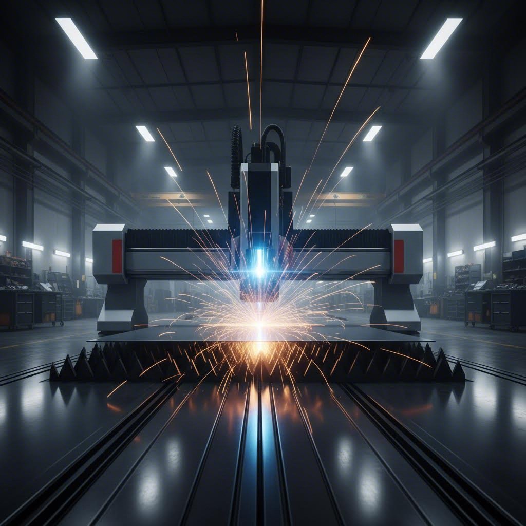
Części przemysłowe często pracują w ekstremalnych warunkach — wysokich temperaturach, agresywnych substancjach chemicznych lub intensywnym obciążeniu mechanicznym. Dlatego producenci stosują zaawansowane techniki, takie jak cięcie laserowe dla precyzji, gięcie prasą hamulcową dla dokładnych kątów oraz spawanie robotyczne dla spójnych połączeń w tysiącach identycznych komponentów.
Różnica w przemysłowej produkcji
Co naprawdę definiuje określenie „przemysłowy” w tym kontekście? Trzy kluczowe czynniki:
- Pojemność produkcyjna: Przemysłowi producenci realizują serie produkcyjne od setek do dziesiątek tysięcy sztuk, utrzymując jakość w każdym elemencie.
- Wymagania dotyczące dokładności: Tolerancje są mierzone w tysięcznych częściach cala, a certyfikaty jakościowe takie jak ISO 9001 zapewniają spójne standardy.
- Wymagania aplikacyjne: Komponenty muszą działać niezawodnie w pojazdach, samolotach, sprzęcie medycznym i infrastrukturze – środowiskach, w których awaria jest niedopuszczalna.
Podczas gdy hobbysta może wykonać pojedynczy niestandardowy uchwyt, przemysłowe operacje obróbki metalu produkują ten sam uchwyt identycznie, powtarzalnie, z dokumentacją śledzącą każdy etap od surowca po gotowy produkt.
Procesy podstawowe kształtujące współczesną produkcję
Kilka podstawowych procesów napędza tę branżę do przodu. Technologie cięcia — w tym laserowe, plazmowe i strumieniowe z użyciem wody — oddzielają metal na łatwe do zarządzania części z zadziwiającą dokładnością. Operacje gięcia i kształtowania następnie formują te elementy za pomocą pras giętarskich i urządzeń tocznych. Na końcu metody łączenia, takie jak spawanie, nitowanie lub łączenie mechaniczne, łączą poszczególne komponenty w spójne zespoły.
Mimo postępów w dziedzinie druku 3D i innych nowych technologii, obróbka blach pozostaje niezastąpiona. Dlaczego? Połączenie efektywności kosztowej w produkcji seryjnej, trwałości materiału oraz różnorodności projektowej nie może być pobitye w większości zastosowań przemysłowych. Zgodnie z analizą branżową, sektor usług związanych z obróbką blach ma wzrosnąć o 3,52 miliarda USD w latach 2021–2026 — co wyraźnie świadczy o tym, że ta metoda produkcji nadal odpowiada na zmieniające się potrzeby przemysłu.
Zrozumienie tych podstaw pozwala na podjęcie świadomych decyzji dotyczących kolejnego projektu z zakresu obróbki blach. W poniższych sekcjach znajdziesz wskazówki dotyczące doboru materiałów, opcji procesowych oraz aspektów jakości, które każdy nabywca przemysłowy powinien znać przed złożeniem zamówienia.
Wybór odpowiedniego metalu dla Twojego zastosowania
Wyobraź sobie, że dobierasz komponenty do zastosowania morskiego. Potrzebujesz odporności na korozję, ale ważna jest również waga. Czy wybierzesz aluminium czy stal nierdzewną? A co z konsekwencjami dla kosztów? Wybór materiału to najprawdopodobniej najważniejsza decyzja, jaką podejmiesz w każdym projekcie gięcia blach – wpływa ona na wszystko, od możliwości wykonania po długoterminową wydajność.
Każdy metal charakteryzuje się innymi właściwościami, a zrozumienie tych różnic pomaga dopasować materiał do wymagań aplikacji. Przeanalizujmy główne opcje i określmy, kiedy każda z nich ma sens w zastosowaniach przemysłowych.
Ramy decyzyjne przy wyborze stali lub aluminium
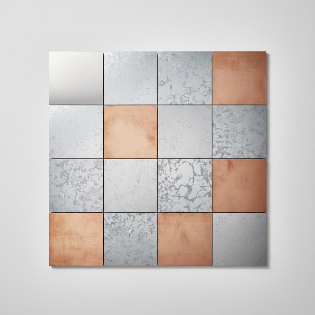
Stal i aluminium to dwa najczęściej stosowane materiały w gięciu blach, jednak służą one fundamentalnie różnym celom. Twoje wyboru między nimi często zależy od trzech czynników: wymagań dotyczących wytrzymałości, ograniczeń związanych z wagą oraz warunków środowiskowych.
Stal, a zwłaszcza stal węglowa, charakteryzuje się doskonałą wytrzymałością na rozciąganie przy niższym koszcie materiału. Gdy priorytetem jest integralność konstrukcyjna, a nie oszczędność masy, stal staje się naturalnym wyborem. Łatwiej ją spawać, jest bardziej wyrozumiała podczas operacji kształtowania i oferuje doskonałą odporność na uderzenia. Jednak standardowa stal węglowa wymaga powłok ochronnych zapobiegających rdzy, co właśnie sprawia, że blacha galwanizowana wkracza do akcji. Powłoka cynkowa zapewnia katodową ochronę przeciwkorozyjną, przez co stal ocynkowana stanowi idealny wybór w zastosowaniach zewnętrznego użytku oraz w elementach systemów klimatyzacji i wentylacji.
Blachy aluminiowe , w porównaniu, waży około jednej trzeciej masy stali, oferując jednocześnie naturalną odporność na korozję. To połączenie czyni ją nieocenioną w przemyśle lotniczym, transporcie oraz wszelkich zastosowaniach, w których redukcja masy przekłada się na korzyści eksploatacyjne. Blacha aluminiowa łatwo poddaje się obróbce skrawaniem i kształtowaniu, choć wymaga specjalistycznych technik spawania oraz ostrożnego obchodzenia się, by nie uszkodzić powierzchni.
Oto praktyczny schemat: jeśli Twój komponent musi wytrzymywać duże obciążenia w chronionym środowisku, warto rozważyć stal. Jeśli priorytetem jest redukcja masy lub odporność na korozję, aluminium zasługuje na poważne rozważenie.
Stal nierdzewna dla wymagających środowisk
Gdy aplikacje wymagają zarówno wytrzymałości, jak i odporności na korozję, płyty metalowe ze stali nierdzewnej stal nierdzewna staje się często jedyną możliwą opcją. W przeciwieństwie do stali węglowej z powłokami ochronnymi, stal nierdzewna osiąga odporność na korozję dzięki zawartości chromu – właściwości wbudowanej w materiał.
Nie wszystkie stale nierdzewne działają jednakowo. Gatunek, który określisz, znacząco wpływa zarówno na możliwość przetwarzania, jak i na wydajność:
- stal nierdzewna 304: Podstawowy gatunek, oferujący doskonałą odporność na korozję w typowych zastosowaniach przemysłowych. Łatwo się spawa i formuje, co czyni go opłacalnym rozwiązaniem dla większości środowisk.
- stal nierdzewna 316: Zawiera molibden, który zapewnia zwiększoną odporność na chlorki i środowiska morskie. Gdy Twoje komponenty są narażone na wodę morską, działanie chemikaliów lub wymagania przetwarzania farmaceutycznego, stal nierdzewna 316 uzasadnia swoje wyższe koszty.
- stal nierdzewna 410: Stal martenzytyczna o dobrej odporności korozyjnej i możliwości ulepszania cieplnego w celu zwiększenia twardości. Nadaje się do komponentów wymagających odporności na zużycie.
- stal nie rdzewiejąca 430: Stal ferrytyczna oferująca wystarczającą odporność korozyjną przy niższym koszcie, powszechnie stosowana w aplikacjach dekoracyjnych i w urządzeniach gospodarstwa domowego.
Pamiętaj, że stal nierdzewna podczas operacji kształtowania ulega umocnieniu odkształceniem plastycznym. Ta właściwość wpływa na wymagania dotyczące narzędzi i może ograniczać osiągalne promienie gięcia w porównaniu ze stalą węglową lub aluminium.
Metale specjalne i ich rola przemysłowa
Oprócz trzech głównych, miedź i mosiądz pełnią funkcje specjalistyczne, gdzie ich unikalne właściwości są niezbędne. Zrozumienie różnicy między mosiądzem a brązem —oraz sytuacji, w których każdy z nich jest odpowiedni—pomaga w prawidłowym doborze materiału do specjalistycznych zastosowań.
Mosiądz, stop miedzi i cynku, łączy doskonałą przewodność elektryczną z naturalnymi właściwościami przeciwdrobnoustrojowymi. Jego przewodność czyni blachę mosiężną niezastąpioną w obudowach elektrycznych i zastosowaniach uziemiających, gdzie stal i aluminium okazują się niewystarczające. Dodatkowo, mosiądz cechuje się estetycznym wyglądem przypominającym złoto, co tłumaczy jego zastosowanie w elementach architektonicznych i dekoracyjnych.
Blacha miedziana charakteryzuje się najwyższą przewodnością elektryczną i termiczną spośród wszystkich powszechnie stosowanych metali przemysłowych. Szyny elektryczne, wymienniki ciepła oraz zastosowania w ekranowaniu promieniowania RF często wymagają niepoddającej się porównaniom przewodności miedzi, pomimo wyższego kosztu materiału.
Porównanie właściwości materiału
Oceniając materiał na potrzeby projektu, należy rozważyć, jak poszczególne właściwości odpowiadają konkretnym wymaganiom:
| Materiał | Moc rozciągania (ksi) | Waga względna | Odporność na korozję | Typowe zastosowania | Koszt względny |
|---|---|---|---|---|---|
| Stal węglowa | 50-80 | Wysoki | Niska (wymaga powłoki ochronnej) | Ramy konstrukcyjne, elementy szkieletu | $ |
| Stal galwanizowana | 50-80 | Wysoki | Umiarkowany | Kanały wentylacyjne, obudowy zewnętrzne | $$ |
| Aluminium (5052-H32) | 33 | Niski | Wysoki | Płyty lotnicze, elementy morskie | $$ |
| nierdzewna stal 304 | 73-90 | Wysoki | Wysoki | Sprzęt gastronomiczny, przemysł ogólny | $$$ |
| 316 ze stali nierdzewnej | 75-95 | Wysoki | Bardzo wysoki | Zastosowania morskie, farmaceutyczne, przetwórstwo chemiczne | $$$$ |
| Mosiądz | 40-70 | Wysoki | Wysoki | Komponenty elektryczne, sprzęt dekoracyjny | $$$$ |
Wpływ grubości na wykonywanie i wydajność
Wybór materiału nie kończy się na określeniu typu metalu — grubość materiału ma równie istotny wpływ na sukces projektu. Zgodnie z Wytycznymi projektowymi Protolabs , minimalna długość płata na elementach blacharskich musi wynosić co najmniej 4-krotność grubości materiału, co pokazuje, jak wybór grubości wpływa na każdą decyzję projektową.
Grubsze materiały zapewniają większą sztywność konstrukcyjną i nośność, ale wymagają potężniejszego sprzętu do formowania. Promienie gięcia muszą rosnąć proporcjonalnie — zbyt ciasny promień na grubym materiale może spowodować pęknięcia. Standardowe opcje promieni gięcia wahają się zwykle od 0,030 cala do 0,120 cala, a dostępność narzędzi wpływa na czas realizacji.
Cieńsze blachy oferują oszczędność wagi i łatwiejsze formowanie, ale mogą wymagać dodatkowego wzmocnienia poprzez zaginanie krawędzi, wykonywanie karbów lub spawane wzmocnienia, aby zapobiec niepożądanemu uginaniu. Przy określaniu cienkich materiałów należy pamiętać, że otwory powinny zachować minimalną odległość od krawędzi – co najmniej 0,062 cala dla materiałów o grubości 0,036 cala lub mniejszej – aby uniknąć odkształceń podczas przebijania lub cięcia.
Implikacje praktyczne dla Twojego projektu
Wybór materiału bezpośrednio wpływa na terminy dostaw i wymagania dotyczące oprzyrządowania. Popularne materiały, takie jak stal konstrukcyjna czy aluminium 5052, zazwyczaj są dostępne u dystrybutorów w ciągu kilku dni, podczas gdy stopy specjalne lub nietypowe grubości mogą wymagać kilku tygodni czasu realizacji. Podobnie wytwórni utrzymują standardowe oprzyrządowanie dla powszechnie stosowanych materiałów, ale egzotyczne specyfikacje mogą wymagać oprzyrządowania niestandardowego – co zwiększa zarówno koszt, jak i czas realizacji projektu.
Przed ostatecznym wyboru materiału warto włączyć partnera od produkcji na wczesnym etapie projektowania. Jego możliwości sprzętu, dostępne zapasy materiałów oraz doświadczenie w pracy z konkretnymi stopami mogą pomóc w określeniu specyfikacji, które zoptymalizują zarówno wydajność, jak i możliwość produkcji. Po dokonaniu wyboru materiału kolejzym krokiem jest zrozumienie procesów produkcyjnych, które przekształcą wybrany metal w gotowe komponenty.
Podstawowe procesy i wyposażenie produkcyjne
Wybrałeś już materiał. Nadchodzi pytanie, które kształtuje cały harmonogram i budżet projektu: które procesy produkcyjne przekształcą ten płaski arkusz w gotowy komponent? Zrozumienie możliwości i ograniczeń każdej metody pozwala skutecznie komunikować się z wykonawcami — a także zapobiega określeniu projektów, które są sprzeczne z prawidłami formowania metali.
Wytwarzanie konstrukcji blacharskich w przemyśle opiera się na dwóch podstawowych kategoriach operacji: procesach cięcia, które oddzielają materiał, oraz procesach kształtowania, które nadają mu formę. Każda technologia oferuje wyraźne zalety w zależności od typu materiału, jego grubości, wymagań dotyczących dokładności i wielkości produkcji.
Technologie cięcia i ich najlepsze zastosowania
Nowoczesne zakłady produkcyjne zazwyczaj oferują wiele metod cięcia, z których każda jest zoptymalizowana pod kątem konkretnych scenariuszy. Wybór odpowiedniej technologii noża do metalu wpływa na jakość krawędzi, dokładność wymiarową oraz koszt pojedynczej części.
Cięcie laserowe dominuje w precyzyjnej i szybkiej pracy z cienkimi i średnimi grubościami materiału. Cięcie laserowe wykorzystuje skoncentrowaną wiązkę światła — pochodzącą z lasera CO2 lub włóknowego — do stopienia, spalenia lub odparowania materiału wzdłuż zaprogramowanych ścieżek. Lasery włóknowe świetnie sprawdzają się przy materiałach odbijających, takich jak miedź i mosiądz, które są trudne do przetwarzania laserami CO2. Zgodnie z danymi firmy Hansen Industries, cięcie laserowe generuje szerokość nacinania (kerf) w zakresie od 0,008 do 0,025 cala, w zależności od grubości materiału — co czyni je idealnym rozwiązaniem dla skomplikowanych geometrii i gęstego rozmieszczenia elementów.
Jednak cięcie laserowe nie jest uniwersalnie lepsze. Elementy stalowe cięte z tlenem jako gazem wspomagającym mogą wykazywać osadzanie się warstwy skalingu na krawędziach, co powoduje problemy podczas spawania i natrysku proszkowego, dlatego często stosuje się gaz azotu, by uzyskać czystsze cięcie.
Wiertarka CNC okazuje się szczególnie skuteczny w przypadku elementów z dużą liczbą otworów — typowym wymaganiem dla obudów i chassis elektronicznych. Proces ten zapewnia lepszą okrągłość otworów niż cięcie laserowe oraz możliwość formowania kształtów i gwintowanie otworów w jednym ustawieniu. Gdy projekt obejmuje żaluzje, tłoczenia lub inne elementy formowane, przebijanie często redukuje konieczność dodatkowych operacji.
Wycinanie wodne staje się metodą preferowaną, gdy grubość materiału zbliża się do pół cala. Ten proces cięcia na zimno wykorzystuje strumień wody pod wysokim ciśnieniem mieszany z cząstkami ściernymi, który erozyjnie usuwa materiał bez stref wpływu ciepła. Można układać wiele arkuszy i ciąć je jednocześnie, a brak odkształceń termicznych oznacza, że elementy są gotowe do spawania i malowania proszkowego bez dodatkowej obróbki.
Obcięcie stanowi najbardziej opłacalne rozwiązanie do prostoliniowych cięć arkuszy materiału. Choć nie posiada elastyczności metod programowalnych, tnienie nożycowe doskonale sprawdza się w szybkim zmniejszaniu dużych arkuszy do rozmiarów przydatnych do dalszej obróbki.
Zrozumienie pojęcia kerfu i jego znaczenie
Czy kiedyś zastanawiałeś się, dlaczego Twoje elementy mogą mieć nieco mniejsze wymiary niż w modelu CAD? Odpowiedzią jest kerf – szerokość materiału usuwanego podczas cięcia. Gdy wiązka lasera lub strumień waterjet przechodzi przez metal, nie tylko rozdziela materiał, ale całkowicie usuwa niewielki kanał materiału.
Szerokość kerfu znacząco różni się w zależności od procesu. Badania nad procesami cięcia laserowego wykazują, że kerf zależy od wielu czynników: wielkości plamki lasera, grubości materiału, pozycji ogniska oraz prędkości cięcia. W przypadku metali typowe szerokości kerfu wynoszą od 0,15 mm do 0,38 mm, natomiast przy cięciu waterjet waha się ona od 0,020 do 0,060 cala, w zależności od konfiguracji mieszadła i dyszy.
Dlaczego to ma znaczenie dla Twojego projektu? Wykonawcy muszą uwzględnić szerokość cięcia (kerf) podczas programowania ścieżek cięcia, a zrozumienie tego pojęcia pomaga w określeniu odpowiednich tolerancji. W przypadku elementów wymagających precyzyjnego dopasowania – takich jak wspólne zamki lub ciasno pasujące zespoły – kompensacja szerokości cięcia staje się kluczowa dla osiągnięcia właściwego pasowania.
Precyzja gięcia i kształtowania wyjaśniona
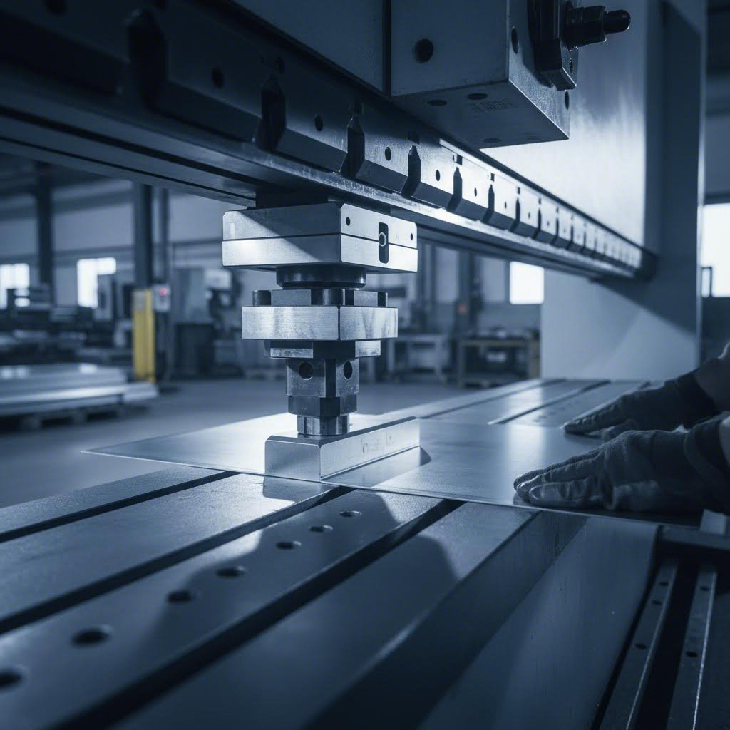
Po wycięciu na kształt płaskie zagotki stają się trójwymiarowymi komponentami dzięki operacjom gięcia i kształtowania. Giętarka mechaniczna pozostaje podstawowym narzędziem przemysłowego kształtowania – maszyną, która dociska materiał pomiędzy tłokiem a matrycą, tworząc precyzyjne zgięcia kątowe.
Podczas oceny możliwości wykonawcy specyfikacje giętarki mechanicznej informują, co jest rzeczywiście osiągalne. Zgodnie z wytycznymi branżowymi dotyczącymi doboru giętarek mechanicznych , najważniejsze są trzy specyfikacje:
- Ocena tonażu: Określa maksymalną siłę gięcia. Wyższa nośność pozwala na gięcie grubszych materiałów i dłuższych zgięć. Standardowy wzór gięcia powietrznego — Siła (tony) = 575 × (Grubość w calach)² × Długość zgięcia w stopach ÷ Otwarcie matrycy w calach — stanowi punkt odniesienia, jednak współczynniki materiałowe różnią się znacznie. Stal nierdzewna wymaga 1,5 do 2,0 razy większej siły niż stal konstrukcyjna; aluminium potrzebuje tylko 0,5 do 0,6 takiej siły.
- Długość stołu: Ogranicza maksymalną szerokość obrabianego przedmiotu. Prasy giętarek przemysłowych obejmują jednostki stołowe o szerokości 4 stóp oraz maszyny o długości 20 stóp lub większej przeznaczone do paneli architektonicznych.
- Dokładność tylnego uchylu: Określa powtarzalność pozycjonowania dla spójnego umiejscowienia zgięć w trakcie serii produkcyjnej.
Nowoczesne prasy giętarki CNC osiągają dokładność pozycjonowania na poziomie ±0,0004 cala w optymalnych warunkach, choć rzeczywista dokładność zależy od spójności materiału, stanu narzędzi oraz ustawienia przez operatora. Kąty zazwyczaj utrzymują się w granicach ±0,5 do 1,0 stopnia dla standardowych zastosowań.
Formowanie na wałkach pełni inną funkcję — tworzy ciągłe profile, takie jak kanały, kątowniki i złożone przekroje, poprzez przeprowadzanie blachy przez kolejne stacje wałków. Ten proces doskonale sprawdza się w produkcji dużych serii spójnych kształtów liniowych.
Kiedy opłaca się tłoczenie
W przypadku produkcji masowej operacje tłoczenia metalu i cięcia matrycowego mogą obniżyć koszt elementów o rząd wielkości w porównaniu z metodami wykonywania poszczególnych części. Matryca progresywna może przebić, uformować i oddzielić części jednym przebiegiem prasy, produkując tysiące identycznych komponentów na godzinę.
W czym jest haczyk? Inwestycja w oprzyrządowanie. Spersonalizowane matryce do operacji tłoczenia wiążą się ze znacznymi kosztami początkowymi, które uzasadnione są zazwyczaj tylko wtedy, gdy wielkość produkcji osiągnie co najmniej 1000 sztuk lub gdy zamówienia powtarzają się wystarczająco często, aby rozłożyć koszty oprzyrządowania. Dla mniejszych serii cięcie laserowe i gięcie na prasie gninarkowej pozostają bardziej opłacalne, mimo wyższego kosztu pojedynczej części.
Operacje wtórne: spawanie, elementy złączne i montaż
Wytworzenie rzadko kończy się cięciem i kształtowaniem. Operacje wtórne przekształcają pojedyncze komponenty w gotowe zespoły.
Spawanie łączy komponenty poprzez lokalne topnienie i spawanie. Zrozumienie różnic między Spawaniem MIG a TIG pomaga w określeniu odpowiednich metod:
- Spawanie MIG (Metal Inert Gas): Używa stale doprowadzanego drutu elektrody, oferując wyższe szybkości napawania i łatwiejszą krzywą uczenia. Idealne dla grubszych materiałów, konstrukcji nośnych i środowisk produkcyjnych, gdzie liczy się szybkość.
- TIG (Tungsten Inert Gas) Spawanie: Zapewnia doskonałą kontrolę i czystsze spoiny przy użyciu niezużywalnej elektrody wolframowej. Preferowane dla cienkich materiałów, widocznych spoin oraz zastosowań wymagających najwyższej jakości – w tym spawania aluminium, gdzie należy zminimalizować porowatość.
Stal nierdzewna i aluminium wymagają specyficznych technik spawania. Spawanie aluminium wymaga szczególnej wiedzy ze względu na wysoką przewodność cieplną materiału i warstwę tlenku, często wymagając spawania TIG prądem zmiennym z odpowiednimi materiałami dodatkowymi.
Wprowadzanie elementów złącznych dodaje gwintowane kołki, dystanse oraz nakrętki wpuszczane bezpośrednio w blachę poprzez wciskanie lub klinowanie. Takie podejście pozwala uzyskać wytrzymałe, wielokrotnie używane gwinty bez dodatkowej masy spawanych nakrętek czy słabej wytrzymałości gwintów wyciętych w blachach.
Operacje montażowe łączy komponenty za pomocą spawania, nitowania lub mechanicznego mocowania — przekształcając wyroby blacharskie w gotowe podzespoły przeznaczone do integracji z większymi systemami.
Główne typy urządzeń i zastosowania przemysłowe
Podczas oceny potencjalnych partnerów wykonawczych, analiza ich parku maszynowego ujawnia rzeczywiste możliwości technologiczne:
- Laser włóknowy (4–12 kW): Szybkie cięcie stali o małej i średniej grubości, aluminium, mosiądzu oraz miedzi. Wyższa moc umożliwia obróbkę grubszych materiałów i szybsze prędkości posuwu.
- Lasery CO2: Uniwersalne cięcie, również niemetali; nadal powszechne w zakładach pracujących z mieszanymi materiałami.
- Pantografy CNC: Stacje z wieloma narzędziami do tworzenia złożonych wzorów otworów, gięcia oraz gwintowania.
- Systemy cięcia strumieniem wody: Cięcie grubych materiałów, materiały wrażliwe na ciepło oraz przetwarzanie warstwowych struktur.
- Giętarki CNC (50–500+ ton): Precyzyjne gięcie z programowalnymi prowadnicami tylnymi i pomiarem kąta.
- Komórki spawalnicze zrobotyzowane: Spawanie seryjne o stałej jakości z możliwością wykorzystania metod MIG lub TIG.
- Prasy do wklejania elementów mocujących: Wkładanie elementów typu PEM i podobnych złączek.
Dobrze znając dostępne procesy obróbki, możesz lepiej projektować pod kątem produkowalności. Kolejnym aspektem — grubością materiału i specyfikacją kalibrów — zależy, które procesy nadają się do konkretnego projektu oraz jakie tolerancje można realistycznie osiągnąć.
Zrozumienie systemu kalibrów i specyfikacji grubości
Oto typowy przypadek: zakładasz stal o grubości 16 kalibru w projekcie, ale dostawca oferuje 14 kalibru. Czy próbują Cię przeforsować, czy może zauważyli błąd w projekcie? Zrozumienie systemu kalibrów — wraz z jego niuansami — pozwala uniknąć kosztownych nieporozumień i zapewnia, że Twoje części będą działać zgodnie z założeniami.
System kalibracji sięga lat 1800, zanim istniały ustandaryzowane pomiary grubości. Zgodnie z Dokumentacją techniczną SendCutSend , producenci pierwotnie mierzyli blachę pod względem wagi, a nie bezpośredniej grubości, ponieważ procesy produkcyjne tego czasu dawały niestabilną grubość. Waga zapewniała bardziej wiarygodną średnią niż pomiar w pojedynczym punkcie.
Wynik? System sprzeczny z intuicją, w którym wyższe numery kalibracji oznaczają cieńszy materiał — odwrotnie niż można by się spodziewać.
Poprawne odczytywanie tabeli kalibracji
Traktuj grubość według kalibru i zmierzoną grubość jak jednostki metryczne i imperialne. Obie opisują tę samą właściwość fizyczną, ale przy użyciu innych konwencji numerowania. Podstawa systemu kalibracji wiąże się z liczbą operacji przeciągania, które historycznie stosowano do zmniejszania średnicy drutu. Każde kolejne przeciągnięcie czyniło drut cieńszym i zwiększało jego numer kalibru.
Tutaj sprawa się komplikuje: różne materiały wykorzystują różne tabele grubości. Tabela grubości blachy stalowej nierdzewnej nie będzie odpowiadać tabeli grubości aluminium — nawet przy identycznych numerach kalibrów. Na przykład, kaliber 12 dla stali nierdzewnej wynosi 0,109 cala, podczas gdy kaliber 12 dla aluminium to 0,080 cala. Różnica wynosi 0,029 cala, co znacznie przekracza dopuszczalne tolerancje w większości zastosowań przemysłowych.
Przed złożeniem zamówienia upewnij się, że korzystasz z odpowiedniej tabeli kalibrów dla danego materiału. Wiele zakładów wytwórczych obecnie podaje grubość w calach dziesiętnych lub milimetrach, aby uniknąć tej niejasności.
Najczęstsze rozmiary kalibrów i zastosowania przemysłowe
Poniższa tabela przedstawia często stosowane rozmiary kalibrów wraz z ich odpowiednikami dziesiętnymi oraz typowymi zastosowaniami. Przy przeglądaniu tabeli wymiarów wierteł lub tabeli rozmiarów wierteł dla specyfikacji otworów pamiętaj, że grubość materiału wpływa na minimalne średnice otworów i odległości od krawędzi.
| Grubość | Grubość stali (cale) | Grubość aluminium (cale) | Typowe Zastosowania Przemysłowe |
|---|---|---|---|
| 22 | 0.030 | 0.025 | Obudowy elektroniczne, lekkie kanały wentylacyjne, panele dekoracyjne |
| 20 | 0.036 | 0.032 | Składniki HVAC, obudowy urządzeń, lekkie elementy konstrukcyjne |
| 18 | 0.048 | 0.040 | Osłony maszyn, ramy szaf, osłony urządzeń |
| 16 | 0.060 | 0.051 | Uchwyty konstrukcyjne, elementy nadwozia, ciężkie obudowy |
| grubość stali 14 gauge | 0.075 | 0.064 | Nośne ramy, komponenty samochodowe, sprzęt przemysłowy |
| grubość stali 11 gauge | 0.120 | 0.091 | Ciężkie prace konstrukcyjne, podstawy maszyn, zastosowania wysokociągowe |
| 10 | 0.135 | 0.102 | Przejścia płytowe, ciężki sprzęt, wzmocnienie konstrukcyjne |
Należy pamiętać, że stal miękka o grubości 12 kalibrów ma 0,105 cala (2,66 mm) grubości — powszechna specyfikacja dla zastosowań konstrukcyjnych średniej wytrzymałości.
Wymagania dotyczące grubości w zależności od typu zastosowania
Jak dobrać odpowiednią grubość dla swojego projektu? Zacznij od wymagań funkcjonalnych:
- Obudowy elektroniczne: zazwyczaj wystarczy grubość 18–22 kalibrów, priorytetem jest redukcja masy i ekranowanie EMI, a nie wytrzymałość konstrukcyjna.
- Instalacje wentylacyjne i klimatyzacyjne: 20–26 gauge w zależności od rozmiaru kanału i klasy ciśnienia, z większymi grubościami dla większych kanałów prostokątnych.
- Elementy podwozia samochodowego: 14–10 gauge dla części nośnych, z określoną grubością na podstawie analizy konstrukcyjnej.
- Ochrony maszyn: 16–14 gauge zapewnia wystarczającą odporność na uderzenia, pozostając jednocześnie formowalne.
Grubość bezpośrednio wpływa na wybór metody obróbki. Cienkie materiały (22 gauge i lżejsze) łatwo tną się laserem, ale mogą ulec odkształceniom podczas gięcia blach stalowych, jeśli promienie gięcia nie są starannie dobrane. Grubsze blachy wymagają mocniejszych pras giętarskich i mogą ograniczać osiągalne kąty gięcia ze względu na ryzyko pęknięcia materiału.
Grubość konstrukcyjna a grubość estetyczna
Nie każda powierzchnia Twojego elementu przenosi obciążenia konstrukcyjne. Projektowanie z zastosowaniem zróżnicowanej grubości — grubszej tam, gdzie liczy się wytrzymałość, i cieńszej tam, gdzie nie ma to znaczenia — zmniejsza wagę i koszt bez utraty wydajności.
Rozważmy typическую obudowę urządzenia. Podstawa może wymagać stali o grubości 14 gauge, aby wspierać komponenty wewnętrzne, podczas gdy boczne panele potrzebują jedynie 18 gauge, ponieważ pełnią głównie funkcję osłon przed kurzem. Problem polega na połączeniu elementów o różnej grubości poprzez spawanie lub łączenie mechaniczne.
Zagadnienie minimalnego promienia gięcia staje się kluczowe wraz ze wzrostem grubości materiału. Ogólna zasada: minimalny wewnętrzny promień gięcia powinien być równy grubości materiału dla stali miękkiej, a dla stali nierdzewnej zwiększa się do 1,5-krotnej grubości. Próba wykonania mniejszych promieni grozi pęknięciami powierzchniowymi na zewnętrznej stronie gięcia – wadą, która narusza zarówno wygląd, jak i integralność konstrukcyjną.
Standardy tolerancji i wymagania dotyczące precyzji
Przemysłowa produkcja skrawaniem odbywa się w ramach określonych standardów tolerancji, które definiują dopuszczalne odchyłki wymiarowe. Zgodnie z Przeglądem technicznym BravoFabs , kilka standardów reguluje dokładność wymiarową:
- ISO 2768: Międzynarodowy standard definiujący klasy dokładności (precyzyjne, średnie, grube, bardzo grube) dla wymiarów liniowych i kątowych.
- ASME Y14.5: Amerykański standard dla geometrycznych ujęć wymiarów i tolerancji (GD&T), określający wymagania dotyczące kształtu, orientacji i położenia.
- ISO 286: Reguluje dopuszczalne odchyłki wymiarowe i pasowania dla elementów walcowych, takich jak wały i otwory.
Wybór standardu zależy od branży, wymaganej precyzji oraz położenia geograficznego. Zastosowania lotnicze zazwyczaj wymagają mniejszych luzów niż typowe zastosowania przemysłowe, co wpływa zarówno na koszt, jak i czas realizacji.
Metody pomiarowe służące do weryfikacji grubości obejmują mikrometry, suwmiarki oraz grubościomierze ultradźwiękowe. W przypadku kontroli materiału przychodzącego większość wytwórców sprawdza grubość w wielu punktach arkusza, ponieważ dopuszczalne odchyłki huty pozwalają na pewne różnice względem nominalnych specyfikacji.
Zrozumienie specyfikacji grubości materiału i wymagań dotyczących tolerancji pozwala precyzyjnie komunikować się z wytwórcami. Następnym krokiem w procesie produkcji — wykończeniu powierzchni i obróbce ochronnej — jest określenie, jak będą działać Twoje komponenty przez cały okres ich użytkowania.

Wykończenie powierzchni i zabiegi ochronne
Twoje wytworzone komponenty zostały przycięte, wygięte i złożone — ale jeszcze nie są gotowe do eksploatacji. Surowe powierzchnie metalowe są narażone na korozję, zużycie i degradację estetyczną od momentu opuszczenia hali produkcyjnej. Wybrany proces wykończeniowy decyduje o tym, czy Twoje części posłużą miesiące czy dziesięciolecia w zamierzonym środowisku.
Zabiegi powierzchniowe robią więcej niż tylko poprawiają wygląd. Tworzą funkcjonalne bariery przeciw wilgoci, substancjom chemicznym, promieniowaniu UV oraz zużyciu mechanicznemu. Wybór niewłaściwego wykończenia — lub całkowite pominięcie tego etapu — może podważyć nawet najdokładniej wykonane komponenty.
Lakierowanie proszkowe dla trwałości przemysłowej
Gdy potrzebujesz wykończenia odpornego na rysy, skaleczenia i korozję, oferującego niemal nieograniczone możliwości kolorystyczne, technologia malowania proszkowego jest idealnym rozwiązaniem. W przeciwieństwie do farb ciekłych, które wykorzystują rozpuszczalniki do przenoszenia pigmentów, malowanie proszkowe używa elektrycznie naładowanych suchych cząstek proszku przylegających do uziemionych powierzchni metalowych przed utwardzeniem cieplnym.
Zgodnie z dokumentacją techniczną firmy Fictiv, proces ten obejmuje trzy kluczowe etapy:
- Przygotowanie powierzchni: Elementy są oczyszczane i dezintegrowane w celu usunięcia olejów i zanieczyszczeń. W niektórych zastosowaniach stosuje się piaskowanie lub strumieniowanie granulatem w celu uzyskania faktury powierzchni poprawiającej przyczepność.
- Naniesienie proszku: Metoda natrysku elektrostatycznego (ESD) nakłada naładowane cząstki proszku na uziemione elementy, zapewniając równomierne pokrycie. W przypadku partii wymagających grubszych powłok (powyżej 10 mil), metoda natrysku fluidalnego polega na bezpośrednim zanurzaniu podgrzewanych elementów w proszku.
- Wypalanie: Elementy są wprowadzane do pieców w temperaturze 325–450°F przez 10–30 minut, co powoduje stopienie proszku i utworzenie ciągłej, trwałej warstwy.
Wyniki mówią same za siebie. Powierzchnie powlekane proszkowo spełniają rygorystyczne standardy wydajności, w tym twardość ołówka (ASTM D3363) i odporność na mgłę solną (ASTM B117). Dzięki efektywności przeniesienia zbliżonej do 98% dzięki możliwemu odzyskowi nadmiaru proszku, usługi natrysku proszkowego minimalizują również odpady w porównaniu z alternatywami ciekłymi.
Powlekanie proszkowe umożliwia spełnienie różnych wymagań estetycznych — dostępne są wykończenia matowe, satynowe, błyszczące, metaliczne oraz teksturowane. Jednak grubość powłoki wymaga starannego kontrolowania; optymalna warstwa filmu w zakresie 2–6 mil zapobiega teksturze typu "skórka pomarańczy", która powstaje w wyniku nadmiernego nałożenia.
Anodowanie i ochrona aluminium
W przypadku elementów aluminiowych anodowanie oferuje ochronę, która jest zasadniczo inna niż powłoki nanoszone. Zamiast dodawania materiału na powierzchnię, proces anodowania przekształca zewnętrzną warstwę aluminium w trwały tlenek poprzez reakcję elektrochemiczną.
Gdy aluminium zanurzy się w kąpieli elektrolitycznej o odczynie kwasowym i zastosuje prąd elektryczny, powierzchnia utlenia się — tworząc integralną warstwę ochronną, która nie może się łuszczyć, odspajać ani odpadać, ponieważ jest dosłownie częścią samego metalu. Valence Surface Technologies wyjaśnia że aluminium anodowane charakteryzuje się zwiększoną odpornością na korozję, większą twardością oraz lepszą odpornością na zużycie w porównaniu z materiałem nieprzetworzonym.
Trzy główne typy spełniają różne potrzeby przemysłowe:
- Typ I (Anodowanie kwasem chromowym): Tworzy cienkie warstwy tlenkowe do 0,0001 cala. Zapewnia niewielką odporność na korozję, ale doskonałą przyczepność w przypadku kolejnych aplikacji farb lub klejów.
- Typ II (Anodowanie kwasem siarkowym): Najczęściej stosowana specyfikacja, produkująca warstwy tlenkowe o grubości od 0,0002 do 0,001 cala. Przyjmuje barwniki, umożliwiając kolorowe wykończenia, oraz oferuje dobrą ochronę przed korozją w ogólnych zastosowaniach przemysłowych.
- Typ III (Anodowanie twardą powłoką): Tworzy warstwy tlenkowe powyżej 0,001 cala, charakteryzujące się znacznie zwiększoną odpornością na zużycie i twardością. Leczenie to jest standardem w zastosowaniach lotniczych, wojskowych oraz tam, gdzie występuje duże obciążenie eksploatacyjne.
Jedna uwaga: anodowanie powoduje przyrost wymiarowy elementów. W przypadku precyzyjnych zespołów należy uwzględnić ten przyrost — zazwyczaj połowa grubości powłoki wnika w metal bazowy, a druga połowa odkłada się na zewnątrz.
Opcje powlekania dla specjalistycznych wymagań
Gdy aplikacje wymagają właściwości wykraczających poza te, które oferują malowanie proszkowe lub anodowanie, procesy powlekania metali osadzają cienkie warstwy ochronnych lub funkcjonalnych metali na powierzchni podłoża.
Galwanizacja nakłada powłoki cynkowe na stal metodą ocynkowania ogniowego lub elektrolitycznego. Zgodnie z Przeglądem technicznym Thai Parkera , ocynkowanie ogniowe polega na zanurzaniu stali w stopionym cynku w wysokich temperaturach, tworząc wiązania metalurgiczne, które przenikają metal bazowy. Powstają w ten sposób wysoce trwałe powłoki, idealne dla stali konstrukcyjnej, sprzętu zewnętrznego oraz zastosowań blach falistych stosowanych jako dachówki i ściany działowe.
Ocynkowanie elektrolityczne natomiast stosuje osadzanie metodą elektrolizy cieńszych warstw cynku, odpowiednich do warunków wewnętrznych lub lekko korozyjnych. Choć mniej odporne niż ocynkowanie ogniowe, ocynkowanie elektrolityczne jest tańsze i dobrze sprawdza się w przypadku elementów łączących, wsporników oraz komponentów wymagających umiarkowanej ochrony.
Dodatkowe opcje powlekania odpowiadają na konkretne wymagania funkcjonalne:
- Wyroby z tworzyw sztucznych Zapewnia doskonałą odporność na korozję z jasnym, dekoracyjnym wykończeniem. Często służy jako podkład pod powłokę chromową.
- Chromowanie: Tworzy twarde, odporne na zużycie powierzchnie o charakterystycznym połysku. Chromowanie dekoracyjne wykorzystuje cienkie warstwy nad niklem; chromowanie twarde nakłada grubsze warstwy dla przemysłowych zastosowań wymagających odporności na zużycie.
- Ocynkowanie cynkowo-niklowe: Łączy ofiarną ochronę cynku z odpornością na korozję niklu, oferując doskonałą wydajność w zastosowaniach motoryzacyjnych i lotniczych.
Porównanie opcji wykończenia
- Powłoka proszkowa: Najlepszy pod względem różnorodności kolorów, odporności na uderzenia oraz przyjazności dla środowiska. Idealny do obudów, osłon urządzeń i produktów skierowanych do klientów.
- Anodyzowanie: Najlepszy dla elementów aluminiowych wymagających zintegrowanej ochrony, stabilności wymiarowej i opcjonalnych kolorów dekoracyjnych. Idealny w przemyśle lotniczym, elektronicznym i budowlanym.
- Galwanizacja metodą poprzeczki ciepłą: Najlepszy w celu maksymalnej ochrony przed korozją stali w surowych warunkach zewnętrznych. Idealny dla konstrukcji stalowych, sprzętu rolniczego i infrastruktury.
- Zinkoplasty: Najlepszy w celu ekonomicznej ochrony przed korozją stali w umiarkowanych warunkach. Idealny dla elementów łączonych, wsporników i urządzeń wnętrz.
- Malowanie mokre: Najlepszy dla niestandardowych kolorów, małych partii i powtórek. Idealny dla prototypów i specjalistycznego dopasowania kolorów.
Wybór odpowiedniego wykończenia dla Twojego środowiska
Wybór wykończenia powinien być dostosowany do środowiska pracy Twojego komponentu. Weź pod uwagę następujące czynniki:
Narażenie na korozję: Środowiska morskie lub chemiczne wymagają trwałości — anodowanie typu III dla aluminium, ocynkowanie ogniowe lub powłoka cynkowo-niklowa dla stali. Zastosowania wewnętrzne mogą wymagać jedynie lakierowania proszkowego lub powłoki cynkowej.
Wymagania dotyczące odporności na zużycie: Komponenty narażone na ścieranie korzystają z twardego anodowania (aluminium) lub chromowania hartowanego (stal). Lakierowanie proszkowe zapewnia odporność na lekkie zadrapania, ale może się łuszczyć przy silnych uderzeniach.
Wymagania estetyczne: Lakierowanie proszkowe oferuje najszerszą paletę kolorów przy zachowaniu spójności wyglądu. Wykończenia anodowane zapewniają odcienie metaliczne od przezroczystych po czarne, z ograniczoną dostępnością jasnych kolorów. Powłoki platerowane dają charakterystyczny metaliczny połysk.
Ekspozycja na temperaturę: Lakierowanie proszkowe zwykle wytrzymuje temperatury ciągłe do 400°F. Powierzchnie anodowane wytrzymują wyższe temperatury bez degradacji. Niektóre procesy platerowania oferują jeszcze większą stabilność termiczną.
Po wybraniu materiału, zdefiniowaniu procesów wytwarzania oraz określeniu wykończenia, poradziłeś sobie z podstawami technicznymi swojego projektu. Kolejnym aspektem—tym, jak różne branże wykorzystują te możliwości—jest pokazanie, w jaki sposób wymagania specyficzne dla danej dziedziny wpływają na decyzje produkcyjne.
Zastosowania przemysłowe i wymagania branżowe
Opanowałeś podstawy—materiały, procesy, grubości blach i wykończenia. Ale oto co naprawdę odróżnia udane projekty realizacji od kosztownych porażek: zrozumienie, w jaki sposób Twoja konkretna branża kształtuje każdą decyzję. Uchwyt przeznaczony do podwozia samochodowego staje przed zupełnie innymi wymaganiami niż ten, który ma chronić wrażliwe elektroniki w szpitalnym środowisku.
Wykonawstwo ze stali, stali nierdzewnej oraz aluminium służy wszystkim tym sektorom—jednak wymagane specyfikacje, certyfikaty i tolerancje różnią się znacząco. Przyjrzyjmy się, jak główne branże wykorzystują przemysłowe gięcie blach i co należy wiedzieć przed złożeniem zamówienia.
Zastosowania w motoryzacji i transporcie
Wyobraź sobie komponent, który musi wytrzymać 150 000 mil drgań drogowych, wahania temperatur od -40°F do 200°F oraz oddziaływanie soli, błota i zanieczyszczeń, jednocześnie spełniając wymagania dotyczące masy, które wpływają na zużycie paliwa. Taka jest rzeczywistość niestandardowych metalowych części samochodowych.
Sektor motoryzacyjny stanowi jednego z największych odbiorców blacharskich elementów produkowanych na zamówienie. Od konstrukcyjnych elementów podwozia po panele karoseryjne i wsporniki wnętrza – niestandardowa produkcja dotyczy niemalże każdego podsystemu pojazdu:
- Elementy szkieletu i konstrukcji nośnej: Podłogi, poprzeczki i wzmocnienia ramy wymagające stali wysokiej wytrzymałości z precyzyjnymi tolerancjami wymiarowymi.
- Wsporniki zawieszenia: Wsporniki i zespoły ramion sterujących wymagające odporności na zmęczenie przy tysiącach cykli obciążeniowych.
- Osłony cieplne: Elementy ze stali nierdzewnej lub stalii aluminiowanej chroniące wrażliwe systemy przed ciepłem spalin.
- Obudowy baterii: Zastosowania w pojazdach elektrycznych wymagające aluminium w celu redukcji masy w połączeniu z ochroną przed kolizjami.
- Wsporniki wnętrza: Ramy siedzeń, podpory deski rozdzielczej i konstrukcje konsoli łączące wytrzymałość z właściwościami tłumienia hałasu.
Co wyróżnia produkcję motoryzacyjną? Wymagania certyfikacyjne. Zgodnie z przewodnikiem certyfikacyjnym Xometry, certyfikat IATF 16949 reprezentuje standard zarządzania jakością w przemyśle motoryzacyjnym, oparty na ISO 9001, ale dostosowany specjalnie do produkcji motoryzacyjnej. Ten certyfikat to nie tylko miła dodatkowa opcja – wielu producentów OEM i dostawców pierwszego rzędu nie weźmie pod uwagę firm zajmujących się obróbką metalu, które nie posiadają tego uprawnienia.
IATF 16949 podkreśla zapobieganie wadom, redukcję różnic oraz eliminację marnotrawstwa w całym łańcuchu dostaw. Różni się od ogólnych systemów jakości tym, że skupia się na aspektach specyficznych dla branży motoryzacyjnej: procesie aprobaty części produkcyjnych (PPAP), zaawansowanym planowaniu jakości produktu (APQP) oraz analizie trybów i skutków uszkodzeń (FMEA). Jeśli Twoje komponenty są wykorzystywane w zastosowaniach motoryzacyjnych, upewnij się, że partner wykonawczy posiada aktualny certyfikat IATF 16949.
Wymagania dokładności w lotnictwie
Gdy komponent ulega awarii na wysokości 35 000 stóp, nie można się po prostu zjechać na pobocze. Zastosowania lotnicze wymagają najwyższych standardów jakości w produkcji przemysłowej — a wymagania certyfikacyjne odzwierciedlają tę rzeczywistość.
Według Przegląd produkcji elementów lotniczych Pinnacle Metal , precyzja ma kluczowe znaczenie w obróbce blach lotniczych, ponieważ skomplikowane komponenty muszą spełniać rygorystyczne допусki i standardy jakości, aby zagwarantować integralność konstrukcyjną i niezawodność końcowych produktów.
Produkcja elementów lotniczych służy aplikacjom takim jak:
- Komponenty konstrukcyjne kadłuba lotu: Żebra, podłużnice i panele osłonowe wymagające obróbki aluminium z tolerancjami mierzonymi w tysięcznych częściach cala.
- Elementy gondoli silnika: Odpornożarne obudowy wykonane z tytanu i stopów o wysokiej zawartości niklu.
- Obudowy systemów pokładowych: Obudowy ekranowane przed zakłóceniami elektromagnetycznymi chroniące czułe systemy pokładowe.
- Komponenty wnętrza kabiny: Konstrukcje kuchni pokładowych, ramy schowków nad głową i prowadnice foteli – równoważenie masy z odpornością na wypadki.
- Sprzęt pomocniczy naziemny: Platformy serwisowe i wózki obsługowe wymagające trwałości w surowych warunkach eksploatacji na stanowiskach postojowych.
Dwa systemy regulacyjne rządzą zgodnością produkcji w przemyśle lotniczym:
FAA (Federal Aviation Administration): Przepisy Lotnictwa Cywilnego (FAR) regulują lotnictwo cywilne w Stanach Zjednoczonych, obejmując certyfikację, materiały, zarządzanie jakością, projektowanie i testy bezpieczeństwa. Ścisłe systemy zarządzania jakością oraz obowiązkowe certyfikaty bezpieczeństwa są wymagane dla komponentów montowanych w certyfikowanych statkach powietrznych.
EASA (Europejska Agencja Bezpieczeństwa Lotniczego): EASA część 21 określa wymagania dotyczące certyfikacji statków powietrznych i ich komponentów, podczas gdy Specyfikacje Certyfikacyjne (CS) definiują wymagania techniczne i bezpieczeństwa. Zatwierdzenia Organizacji Produkcyjnych (POA) zapewniają, że procesy produkcyjne spełniają europejskie standardy.
Dla wytwórców obsługujących klientów z branży lotniczej, certyfikat AS9100D potwierdza zgodność z przemysłowymi standardami jakości. Certyfikat ten opiera się na ISO 9001, uzupełniając ją o wymagania specyficzne dla branży lotniczej dotyczące zarządzania ryzykiem, kontroli konfiguracji oraz zapobiegania fałszerstwom części.
Składniki systemów klimatyzacji i instalacji budowlanych
Przechodząc przez dowolny budynek użyteczności publicznej, otaczają Cię wyroby blacharskie — często bez tego zdawania sobie sprawy. Kanały wentylacyjne, obudowy urządzeń, przepusty i panele serwisowe powstają wszystkie w oparciu o te same podstawowe procesy, zoptymalizowane pod kątem działania systemów budowlanych.
Zastosowania w systemach HVAC stawiają inne priorytety niż prace w motoryzacji czy lotnictwie:
- Kanały wentylacyjne: Prostokątne i okrągłe kanały z blachy ocynkowanej, dobrane rozmiarem zgodnie ze standardami SMACNA, z grubością blachy określoną na podstawie wymiarów kanału i klasy ciśnienia.
- Obudowy jednostek centralnych: Duże obudowy wymagające uszczelniania szwów w celu osiągnięcia szczelności powietrznej oraz konstrukcji z przerwą termiczną w celu zwiększenia efektywności.
- Ramki przepustnic: Precyzyjna kontrola wymiarów zapewniająca odpowiednie dopasowanie i uszczelnienie łopatek.
- Obsługa urządzeń: Wykonanie konstrukcji stalowych dla podstaw jednostek dachowych i platform w pomieszczeniach technicznych.
- Okapniki architektoniczne: Wykonanie z aluminium, które równoważy przepływ powietrza, ochronę przed deszczem oraz spełnia wymagania estetyczne.
Projektowanie pod kątem możliwości produkcji (DFM) ma inne zastosowanie w systemach HVAC. W przeciwieństwie do elementów lotniczych produkowanych w partiach o ciasnych tolerancjach, komponenty HVAC często wymagają dopasowania i modyfikacji na budowie. Doświadczeni wytwórcy projektują ze względu na możliwość regulacji oraz standardowe metody łączenia, które umożliwiają dostosowanie do warunków rzeczywistego montażu.
Zastosowania w elektronice i sprzęcie medycznym
Obudowy elektroniczne i ramy sprzętu medycznego mają wspólny wymóg: ochrona wrażliwych zawartości przy jednoczesnym spełnieniu branżowych standardów. Spersonalizowane metalowe obudowy w tych sektorach balansują ekranowanie EMI, zarządzanie temperaturą oraz aspekty estetyczne.
Zastosowania w elektronice obejmują:
- Stojaki i szafy serwerowe: Obudowy precyzyjne z wbudowanym zarządzaniem przewodami i chłodzeniem.
- Obudowy paneli sterowania: Obudowy ocenione zgodnie z normą NEMA, zapewniające ochronę środowiskową dla urządzeń przemysłowych.
- Obudowy ekranujące RF: Specjalna konstrukcja zapobiegająca zakłóceniom elektromagnetycznym.
- Szafy telekomunikacyjne: Obudowy przeznaczone do użytku zewnętrznego, odporne na skrajne temperatury i wilgoć.
Wytwarzanie sprzętu medycznego wymaga dodatkowych rozważań:
- Ramy sprzętu diagnostycznego: Konstrukcje aparatów MRI i CT wymagające niemagnetycznych materiałów oraz ekstremalnej stabilności wymiarowej.
- Obudowy sprzętu chirurgicznego: Wykonanie ze stali nierdzewnej umożliwiające sterylizację i odporność na korozję.
- Ramy łóżek pacjentów: Konstrukcje nośne spełniające standardy trwałości, ułatwiające jednocześnie czyszczenie.
- Obudowy sprzętu laboratoryjnego: Odporność chemiczna powłok chroniących przed agresywnymi odczynnikami.
Wykonywanie urządzeń medycznych często wymaga rejestracji w FDA oraz zgodności ze standardami zarządzania jakością ISO 13485 — kolejny poziom certyfikacji wykraczający poza ogólne wymagania przemysłowe.
Zastosowanie zasad DFM w różnych sektorach
Projektowanie pod kątem łatwości produkcji oznacza różne rzeczy w różnych branżach. W motoryzacji priorytetem są projekty umożliwiające szybką produkcję automatyczną przy minimalnej zmienności. W lotnictwie nacisk kładzie się na projekty ułatwiające inspekcję i dokumentację na każdym etapie. Klimatyzacja koncentruje się na projektach dostosowanych do warunków terenowych i instalacji przez wykwalifikowanych fachowców.
Niezależnie od sektora, skuteczne DFM bierze pod uwagę:
- Dobór materiałów zgodny zarówno z wymaganiami wydajnościowymi, jak i możliwościami produkcyjnymi
- Specyfikacje tolerancji dostosowane do potrzeb funkcjonalnych — nie ostrzejsze niż to konieczne
- Projekty elementów, które mogą być skutecznie wytwarzane za pomocą standardowego narzędziowania
- Sekwencje montażowe minimalizujące manipulację i prace poprawkowe
- Specyfikacje wykończenia dostosowane do warunków ekspozycji środowiskowej
Współpraca z firmami zajmującymi się obróbką metali, które mają doświadczenie w Twoim konkretnym sektorze, przyspiesza tę optymalizację. Już wcześniej rozwiązywały podobne problemy i mogą wskazać kierunek ku sprawdzonym rozwiązaniom
Zrozumienie wymagań sektora pozwala na efektywną komunikację z potencjalnymi partnerami produkcyjnymi. Kolejnym kluczowym aspektem — standardami jakości oraz realistycznymi harmonogramami produkcji — zależy, czy Twój projekt zostanie zrealizowany na czas i zgodnie z założeniami
Standardy jakości i harmonogramy produkcji
Zidentyfikowałeś swój materiał, określiłeś procesy produkcji i ustaliłeś, które certyfikaty branżowe dotyczą Twojego projektu. Nadchodzi pytanie, które może zadecydować o sukcesie lub porażce harmonogramu produkcji: w jaki sposób zweryfikować, że Twój partner produkcyjny rzeczywiście dostarcza obiecaną jakość — i ile czasu to rzeczywiście potrwa?
Certyfikaty jakości zapewniają ustandaryzowane ramy oceny możliwości precyzyjnej obróbki blachy. Jednak te kwalifikacje wiele nie znaczą, jeśli nie rozumie się, czego faktycznie wymagają i jak przekładają się one na konkretny projekt. Podobnie oczekiwania dotyczące harmonogramu muszą uwzględniać pełny zakres prac — od przeglądu inżynieryjnego po końcową inspekcję.
Rozszyfrowane standardy certyfikacji
Szukając fraz „metal fabrication companies near me” lub „sheet metal fabrication shops near me”, napotkasz różne deklaracje certyfikatów. Zrozumienie, jakie wymagania stawia każdy z certyfikatów, pozwala odróżnić rzetelnych partnerów od tych, którzy jedynie spełniają formalne kryteria.
ISO 9001:2015 stanowi podstawę zarządzania jakością w różnych branżach. Ten międzynarodowy standard określa kryteria dla systemu zarządzania jakością oparte na kilku zasadach: silnym skupieniu na kliencie, zaangażowaniu kierownictwa, podejściu procesowym oraz ciągłej poprawie. Zgodnie z Dynamic Design and Manufacturing , organizacja posiadająca rejestrację ISO 9001 musi przeprowadzać regularne audyty wewnętrzne w celu weryfikacji działania swojego systemu zarządzania jakością, a także poddawać się okresowym audytom zewnętrznym przeprowadzanym przez niezależny organ certyfikujący.
AS9100D bazuje na ISO 9001, ale jest dostosowane specjalnie do zastosowań lotniczych. Certyfikat ten obejmuje dodatkowe wymagania kluczowe dla bezpieczeństwa lotniczego: zarządzanie konfiguracją, zarządzanie ryzykiem, zapobieganie fałszerstwom części oraz aspekty związane z czynnikiem ludzkim. Dostawcy blacharki metalowej obsługujący klientów z branży lotniczej muszą posiadać ten certyfikat, aby uczestniczyć w większości łańcuchów dostaw — nie jest to opcjonalne.
IATF 16949 odnosi się do wymagań przemysłu motoryzacyjnego ze szczególnym naciskiem na zapobieganie wadom i redukcję odchyleń. Poza ogólnymi zasadami jakości obowiązują tutaj konkretne narzędzia stosowane w motoryzacji: Proces Zatwierdzania Części Produkcyjnych (PPAP), Zaawansowane Planowanie Jakości Produktu (APQP) oraz metody statystycznej kontroli procesu.
Przed przyznaniem umowy sprawdź, czy certyfikaty są aktualne, wydane przez akredytowane instytucje certyfikujące oraz czy obejmują one konkretne procesy wymagane przez Twój projekt. Dostawca certyfikowany do cięcia laserowego nie posiada automatycznie certyfikatu na spawanie ani obróbki wykończeniowe.
Zapewnienie jakości w seriach produkcyjnych
Certyfikaty tworzą systemy – ale to, co dzieje się na hali produkcyjnej, decyduje o rzeczywistej jakości. Dostawcy wyrobów ze stali i producenci wyrobów blacharskich stosują różne metody zapewniania jakości w zależności od wymagań aplikacji.
Inspekcja pierwszego sztucznego elementu (FAI) potwierdza, że procesy produkcyjne są w stanie konsekwentnie wytwarzać części zgodne z określonymi parametrami. Zgodnie z Fox Valley Metal-Tech przedsiębiorstwo zajmujące się obróbką metali najprawdopodobniej będzie musiało dostarczyć raport z inspekcji pierwszego sztucznego elementu oraz mapowanie spoin, aby zweryfikować, że produkty odpowiadają specyfikacjom klienta przed przystąpieniem do produkcji seryjnej.
Inspekcja bieżąca pozwala wykryć odchylenia, zanim rozprzestrzenią się one na kolejne operacje. Kontrole wymiarowe na etapach cięcia, gięcia i montażu zapobiegają narastaniu błędów, które mogłyby wymagać kosztownej poprawki lub doprowadzić do utylizacji produktu.
Inspekcja końcowa weryfikuje ukończone zespoły pod kątem zgodności z rysunkami technicznymi. Może ona obejmować:
- Weryfikację wymiarową za pomocą maszyny pomiarowej CMM (Coordinate Measuring Machine), suwmiarek i wzorców
- Inspekcja wizualna pod kątem wad powierzchniowych, jakości spoin i spójności wykończenia
- Testowanie funkcjonalne zespołów z elementami ruchomymi lub krytycznymi pasowaniem
- Badania niszczące próbek części przeznaczonych do krytycznych zastosowań konstrukcyjnych
Wymagania dotyczące inspekcji i dokumentacji
W przypadku wielu zastosowań przemysłowych dostarczenie wysokiej jakości części nie wystarcza — potrzebna jest dokumentacja potwierdzająca, że spełniają one określone parametry. W tym miejscu kluczową rolę odgrywają pakiety danych jakości (QDP).
QDP zawiera zestaw raportów udokumentowanych śladów pochodzenia materiałów, procesów oraz certyfikatów wykorzystanych przy produkcji każdego elementu. Jak wyjaśnia dokumentacja branżowa, pakiety te mogą obejmować:
- Certyfikaty zgodności: Dokumentację potwierdzającą pochodzenie materiałów, wyniki badań oraz klasyfikacje. Klienci rządowi zazwyczaj wymagają tego dla surowców, elementów zamocowań i materiałów eksploatacyjnych.
- Certyfikaty Materiałowe: Raporty badawcze hutnicze potwierdzające skład chemiczny i właściwości mechaniczne materiałów wejściowych.
- Certyfikaty procesu: Dokumentacja obróbki cieplnej, powłok chemicznych, pasywacji, malowania oraz procesów wykończeniowych.
- Kwalifikacje spawaczy: Status certyfikacji spawaczy, inspektorów spawalniczych oraz programów spawania.
- Zapisy inspekcji: Raporty FAI, wyniki kontroli wymiarów oraz potwierdzenie, kto wykonał pracę i inspekcje.
- Raporty odchyleń: Dokumentacja wszelkich zatwierdzonych zmian w stosunku do oryginalnych specyfikacji.
W zależności od złożoności projektu dokumentacja QDP może liczyć setki stron. Projekty obronne z rozbudowanymi wymaganiami przekazanymi dalej generowały zestawy przekraczające 1000 stron. Kluczowa wskazówka: wcześniejsze poinformowanie partnera zajmującego się produkcją blacharską o wymaganiach QDP ułatwia zbieranie danych i zapobiega kosztownym opóźnieniom.
Realistyczne harmonogramy produkcji
Ile czasu rzeczywiście trwa produkcja przemysłowa? Szczera odpowiedź: zależy to od czynników, które możesz kontrolować, oraz od tych, których nie możesz.
Według Analiza wytwórcy , planowanie produkcji metali niestandardowych stara się wprowadzić porządek w chaosie. Większość warsztatów produkcyjnych nie ma luksusu linii produkcyjnej, a wąskie gardło może się zmieniać w zależności od rodzaju zleceń — czasem jest to gięcie, innym razem spawanie lub wykończenie.
Czynniki wpływające na czas realizacji:
- Złożoność: Elementy o dużej liczbie operacji, małych tolerancjach lub skomplikowanych złożeniach wymagają więcej czasu na przetwarzanie i weryfikację jakości.
- Objętość: Większe ilości nie powodują proporcjonalnego wydłużenia czasu realizacji — czas przygotowania jest rozłożony, jednak ograniczenia pojemności mogą przedłużyć harmonogram.
- Dostępność materiałów: Typowe materiały, takie jak stal konstrukcyjna czy aluminium 5052, zazwyczaj są wysyłane w ciągu kilku dni. Specjalistyczne stopy lub nietypowe grubości materiałów mogą wymagać kilku tygodni na dostawę.
- Wymagania dotyczące wykończenia: Zewnętrzne procesy, takie jak malowanie proszkowe, powlekanie galwaniczne lub anodowanie, dodają dni lub tygodnie, w zależności od możliwości dostawcy.
- Przegląd inżynieryjny: Analiza DFM i wyjaśnienie rysunków może wydłużyć harmonogram, jeśli projekty wymagają modyfikacji.
- Dokumentacja: Rozbudowane wymagania QDP wiążą się z dodatkowym czasem potrzebnym na zebranie danych, nawet po ukończeniu elementów.
Planowanie prototypu a produkcji seryjnej
Harmonogramy dla prototypów i produkcji seryjnej opierają się na zasadniczo innych zasadach. Zrozumienie tej różnicy zapobiega nierzeczywistym oczekiwaniom.
Prototypów priorytetem jest szybkość i elastyczność. Wykonawcy często przyspieszają prace prototypowe, aby wspierać harmonogramy rozwojowe klientów, czasem kończąc pierwsze egzemplarze w ciągu kilku dni zamiast tygodni. Jednak ta szybkość wiąże się z ograniczeniami: oprzyrządowanie może być tymczasowe, kontrola jakości skrócona, a dokumentacja minimalna.
Ciągi produkcji priorytetem jest spójność i efektywność. Początkowe przygotowanie trwa dłużej — wymagane jest trwałe oprzyrządowanie, zweryfikowane procesy oraz ustalone protokoły kontroli — ale czas produkcji pojedynczej sztuki znacząco się zmniejsza. Prototyp, który można wykonać w 5 dni, może wymagać 3–4 tygodni kwalifikacji produkcyjnych przed rozpoczęciem masowej produkcji.
Przejście od prototypu do produkcji często ujawnia problemy projektowe, które nie miały znaczenia przy małych seriach. Cechy, które wykwalifikowany operator mógł obejść przy dziesięciu sztukach, stają się problemami jakościowymi przy dziesięciu tysiącach sztuk. Inteligentni partnerzy produkcyjni wykrywają te problemy już podczas przeglądu DFM, a nie w trakcie produkcji.
Zgodnie z ekspertami ds. planowania, inteligentne harmonogramowanie polega na uruchamianiu materiału w odpowiednim czasie. Zadania uruchamiane zbyt wcześnie gromadzą się jako produkcja w toku przy wąskich gardłach. Zadania uruchamiane zbyt późno narażone są na przekroczenie terminów. Odnalezienie optymalnego momentu — dzięki doświadczeniu, planowaniu zdolności produkcyjnych i oprogramowaniu do planowania — pozwala zadaniom płynnie przechodzić z jednego centrum pracy do drugiego.
Gdy normy jakości są dobrze zrozumiane, a realistyczne ramy czasowe ustalone, jesteś gotów do podjęcia ostatniej kluczowej decyzji: wyboru partnera ds. obróbki metalu, którego możliwości odpowiadają wymaganiom Twojego projektu.
Wybór odpowiedniego partnera w zakresie wykonywania blach
Wykonałeś swoją pracę domową — znasz materiały, procesy, tolerancje i wymagania branżowe. Nadszedł moment decyzji, która wszystko ze sobą łączy: który partner ds. obróbki rzeczywiście ożywi Twój projekt? Wyszukiwanie frazy "obróbka metalu w mojej okolicy" lub "zakłady obróbki metalu w pobliżu" daje dziesiątki wyników, ale możliwości tych firm diametralnie różnią się mimo podobnych opisów.
Prawidłowym partnerstwo rozciąga się daleko poza konkurencyjne ceny. Zgodnie z wytycznymi TMCO dotyczącymi obróbki metali, wybór odpowiedniego partnera w zakresie tłoczenia metalu to decyzja krytyczna — która może wpływać na koszty, wydajność, jakość oraz długoterminową niezawodność projektu. Skoro tak wiele firm oferuje podobne usługi, ocena czynników innych niż cena jest niezbędna.
Ocena możliwości producenta
Gdy szukasz frazy „metal fabricators near me” lub „sheet metal fabrication near me”, czego powinieneś właściwie szukać? Zacznij od dopasowania ich sprzętu do potrzeb Twojego projektu.
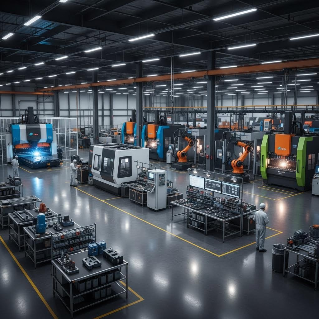
Nie wszystkie warsztaty zajmujące się obróbką metalu oferują ten sam poziom możliwości. Niektóre jedynie tną metal, podczas gdy inne outsource’ują obróbkę skrawaniem, wykończeniem czy montażem — co prowadzi do opóźnień, luki w komunikacji oraz niestabilnej jakości. Kompleksowe, zintegrowane zakłady umożliwiają optymalizację całego procesu w jednym miejscu, zapewniając lepszą kontrolę nad produkcją i krótsze czasy realizacji.
Zanim skontaktujesz się z jakimkolwiek zakładem, jasno określ wymagania swojego projektu:
- Specyfikacje materiału: Czy wytwórca pracuje z wymaganymi przez Ciebie metalami — takimi jak stal nierdzewna, aluminium czy stopy specjalne?
- Zakres Grubości: Czy ich wyposażenie radzi sobie z wymaganą grubością materiału, od cienkich obudów elektronicznych po ciężkie elementy konstrukcyjne?
- Wymagania dotyczące tolerancji: Czy regularnie osiągają precyzję niezbędną do Twojego zastosowania?
- Wymagania co do wielkości produkcji: Czy są przygotowani na wytwarzanie prototypów, partii produkcyjnych lub obu tych opcji?
- Wymagania certyfikacyjne: Czy posiadają certyfikaty branżowe wymagane przez Twój łańcuch dostaw?
Kluczowe możliwości, które należy zweryfikować podczas oceny warsztatu blacharskiego w pobliżu to:
- Możliwości cięcia laserowego, plazmowego lub wodnego
- Wyposażenie do obróbki CNC i precyzyjnego gięcia
- Gięcie hamulca prasą z odpowiednią siłą i długością stołu
- Spawanie TIG/MIG oraz komórki spawalnicze zrobotyzowane
- Powłoki proszkowe, anodowanie lub powlekanie metalizacyjne
- Montaż, wklejanie elementów złącznych i wsparcie przy testowaniu
Partner wyposażony w nowoczesny sprzęt i automatykę zapewnia powtarzalność, efektywność oraz możliwość skalowania wraz z rozwojem Twoich potrzeb.
Wartość wsparcia inżynieryjnego
Oto co odróżnia przeciętnych wykonawców od wyjątkowych: współpraca inżynieryjna. Sukces w wykonywaniu nie zaczyna się przy maszynie — zaczyna się od przeglądu inżynieryjnego.
Zgodnie z analizą prototypowania Fictiv, informacje zwrotne dotyczące projektowania pod kątem technologii (DFM) podczas procesu wyceny pomagają zoptymalizować projekty nie tylko dla prototypowania, ale również dla produkcji seryjnej. Wczesne spostrzeżenia umożliwiają lepszą wydajność, obniżenie kosztów i zmniejszenie liczby problemów na późniejszych etapach.
Niezawodny wytwórca będzie współpracował z Tobą od wczesnych etapów procesu, przeglądając rysunki, pliki CAD, tolerancje oraz wymagania funkcjonalne. Oceniając potencjalnych partnerów, zapytaj, czy oferują:
- Wsparcie CAD/CAM: Czy mogą pracować bezpośrednio z Twoimi plikami projektowymi i wykrywać problemy przed rozpoczęciem produkcji?
- Konsultacje DFM: Czy inżynierowie przeanalizują Twoje projekty pod kątem możliwości produkcyjnych i zaproponują ulepszenia?
- Testowanie prototypu: Czy oferują szybkie prototypowanie w celu weryfikacji projektów przed przystąpieniem do produkcji narzędzi?
- Rekomendacje materiałowe: Czy mogą doradzać w zakresie optymalnego doboru materiałów na podstawie Twoich wymagań eksploatacyjnych?
Taki poziom wsparcia zmniejsza ryzyko, skraca czas realizacji i zapewnia płynny przebieg produkcji — szczególnie w przypadku złożonych zespołów. Doświadczony menedżer projektu lub przedstawiciel powinien przeprowadzić Cię przez cały proces produkcji z pewnością i jasnością.
Od prototypu do partnerstwa produkcyjnego
Twoim idealnym partnerem jest ten, który potrafi wspierać zarówno obecne potrzeby, jak i przyszły rozwój. Umiejętność skalowania produkcji od prototypów po pełne serie produkcyjne bez utraty jakości wyróżnia prawdziwych partnerów produkcyjnych spośród zwykłych warsztatów.
Możliwości szybkiego prototypowania stały się kluczowym czynnikiem różnicującym. Gdy terminy rozwoju skracają się, oczekiwanie kilku tygodni na pierwsze sztuki nie jest akceptowalne. Wiodący dostawcy oferują teraz realizację prototypów w ciągu 5 dni, umożliwiając inżynierom szybką weryfikację projektów i iteracje bez opóźnień w harmonogramie. Ta szybkość, w połączeniu z kompleksowym wsparciem DFM, przyspiesza cały cykl rozwoju produktu.
W przypadku zastosowań motoryzacyjnych certyfikat IATF 16949 pozostaje warunkiem koniecznym do integracji z łańcuchem dostaw. Partnerzy tacy jak Shaoyi (Ningbo) Metal Technology pokazują, jak te możliwości się łączą: certyfikowana jakość według IATF 16949 dla podwozia, zawieszenia i elementów konstrukcyjnych, w połączeniu z szybkim prototypowaniem w ciągu 5 dni oraz przygotowaniem ofert w ciągu 12 godzin dla potrzeb niestandardowej obróbki blachy lokalnie. Takie połączenie certyfikacji, szybkości i wsparcia inżynieryjnego stanowi przykład tego, czego producenci motoryzacyjni powinni oczekiwać od partnerów wykonawczych.
Równie istotna jest przejrzysta komunikacja. Niezawodny wytwórca zapewnia jasne harmonogramy, aktualizacje projektu oraz realistyczne oczekiwania. Skuteczna komunikacja zapobiega kosztownym niespodziankom i utrzymuje projekty na dobrej drodze od początku do końca.
Lista kryteriów oceny partnera
Przed podjęciem ostatecznej decyzji należy systematycznie ocenić potencjalnych partnerów pod kątem poniższych kryteriów:
- Doświadczenie i historia realizacji: Jak długo już wykonują skomplikowane detale metalowe? Czy mogą przedstawić przykłady lub referencje z Państwa branży?
- Możliwości własne: Czy samodzielnie realizują wszystkie kluczowe procesy, czy korzystają z subdostawców, co wydłuża czas realizacji i wprowadza zmienność?
- Certyfikaty: Czy aktualne certyfikaty ISO 9001, AS9100D lub IATF 16949 zostały wydane przez akredytowane instytucje certyfikujące?
- Wsparcie inżynieryjne: Czy oferują przegląd DFM, wytwarzanie prototypów i konsultacje projektowe?
- Systemy jakości: Jakie metody kontroli, dokumentacji i śledzenia oferują?
- Skalowalność: Czy są w stanie obsłużyć ilości potrzebne do prototypów oraz zwiększyć produkcję do pełnych wielkości serii?
- Komunikacja: Czy zapewniają dedykowane zarządzanie projektem i regularne aktualizacje statusu?
- Czasy realizacji: Czy podane terminy są realistyczne i czy mają dobre historie dotrzymania zobowiązań czasowych?
Szukając bliskiego dostawcy gięcia blach, pamiętaj, że geograficzna bliskość jest mniej ważna niż dopasowanie możliwości. Partner oddalony o 500 mil, ale posiadający odpowiednie wyposażenie, certyfikaty i wsparcie inżynieryjne, osiągnie lepsze wyniki niż lokalny warsztat pozbawiony kluczowych kompetencji.
Podejmowanie ostatecznej decyzji
Zatrudnienie dostawcy usług gięcia nie jest tylko decyzją zakupową — to długoterminowa inwestycja w wydajność i niezawodność Twoich produktów. Odpowiedni partner oferuje wsparcie techniczne, zaawansowane technologie, solidne systemy jakości oraz podejście współpracy, które dodaje wartość wykraczającą poza sam metal.
Jak podkreśla Atscott MFG, wybór odpowiedniego partnera w zakresie obróbki metali to coś więcej niż kwestia ceny — chodzi o znalezienie wiarygodnego eksperta, który będzie w stanie zapewnić wysoką jakość pracy na każdym etapie procesu.
Zażądaj ofert od kilku dostawców, ale oceniaj odpowiedzi kompleksowo. Najniższa cena często odzwierciedla brakujące kompetencje lub nierealistyczne założenia. Najlepszą wartością charakteryzują się partnerzy, którzy rozumieją Twoje wymagania, proaktywnie wykrywają potencjalne problemy i zapewniają stabilną jakość zgodnie z harmonogramem.
Zaufanego partnera produkcyjnego nie tylko produkuje części, ale wspierają Twoje cele, poprawiają produkt i pomagają w pozycjonowaniu projektu na długoterminowy sukces. Dzięki odpowiednim partnerom, projekty produkcji blach przemysłowych mogą przejść z koncepcji do produkcji z ufnością.
Często zadawane pytania dotyczące produkcji metalu arkuszowego
1. Ile kosztuje obróbka blach?
Koszty produkcji blach metalowych różnią się w zależności od rodzaju materiału, grubości, złożoności i objętości. Średnio koszty wahają się od 4 do 48 dolarów za metr kwadratowy w zależności od wymagań dostosowania. Proste części z użyciem zwykłych materiałów, takich jak miękka stal, kosztują mniej, podczas gdy złożone zespoły z użyciem stali nierdzewnej lub wymagające ścisłych tolerancji i specjalistycznych wykończeń zwiększają ceny. Uzyskanie ofert od producentów certyfikowanych IATF 16949 z możliwością realizacji w ciągu 12 godzin pomaga szybko porównać opcje.
2. Wykorzystanie Jaka jest różnica między prototypem a terminem produkcji?
Harmonogramy prototypów priorytetowo traktują szybkość, często kończąc pierwsze sztuki w ciągu 5 dni dzięki przyspieszonym procesom i tymczasowym narzędziom. Serie produkcyjne wymagają dłuższego przygotowania — zazwyczaj 3–4 tygodnie na kwalifikację — ponieważ wiążą się z użyciem stałych narzędzi, zweryfikowanych procesów oraz ustalonych protokołów kontroli jakości. Jednak czas przetwarzania pojedynczej części znacząco maleje po uruchomieniu produkcji. Współpraca z dostawcami oferującymi szybkie prototypowanie oraz możliwości zautomatyzowanej masowej produkcji zapewnia płynny przejście między fazą rozwojową a pełną produkcją.
3. Jakie certyfikaty powinna posiadać firma zajmująca się obróbką metalu?
Wymagane certyfikaty zależą od branży. Podstawowym standardem zarządzania jakością jest ISO 9001:2015. Zastosowania motoryzacyjne wymagają certyfikatu IATF 16949 w celu integracji z łańcuchem dostaw, obejmującego zapobieganie wadom oraz procesy zatwierdzania partii produkcyjnych. Produkcja dla przemysłu lotniczego wymaga certyfikatu AS9100D z dodatkowymi wymaganiami dotyczącymi zarządzania konfiguracją i zapobiegania fałszerstwom. Zawsze upewnij się, że certyfikaty są aktualne, wydane przez akredytowane instytucje certyfikujące oraz obejmują konkretne wymagane procesy.
4. Jakie materiały są powszechnie stosowane w przemyślowej produkcji blach?
Najczęściej stosowanymi materiałami są stal węglowa do zastosowań konstrukcyjnych, stal ocynkowana dla odporności na korozję, aluminium do elementów wrażliwych na wagę oraz stal nierdzewna (gatunki 304 i 316) do wymagających warunków. Metale specjalne, takie jak miedź i mosiądz, służą w zastosowaniach wymagających przewodności elektrycznej i cieplnej. Wybór materiału wpływa na metodę wyrobu, wymagania dotyczące narzędzi, terminy realizacji i koszty, dlatego wcześniejsza konsultacja z doświadczonymi wytwórcami jest wartościowa dla optymalizacji zarówno wydajności, jak i możliwości produkcji.
5. Jak wybrać odpowiedniego partnera produkcyjnego do mojego projektu?
Oceń dostawców pod kątem możliwości sprzętu odpowiadających Twoim wymaganiom, certyfikatów branżowych, wsparcia inżynieryjnego wewnętrznej firmy dla przeglądu DFM oraz skalowalności od prototypów do produkcji seryjnej. Kluczowe czynniki różnicujące to szybki czas realizacji prototypów (5 dni lub mniej), kompleksowa dokumentacja jakości, przejrzysta komunikacja oraz dedykowane zarządzanie projektem. Partnerzy oferujący usługi zintegrowane — cięcie, kształtowanie, spawanie i wykańczanie w jednym miejscu — zapewniają lepszą kontrolę jakości i szybszą dostawę niż firmy korzystające z podwykonawców.