 Maži serijos dydžiai, aukšti standartai. Mūsų greito prototipavimo paslauga leidžia patvirtinti rezultatus greičiau ir lengviau —

Lazerio pjaustymo detalės išaiškintos: nuo žaliavinio metalo iki beklaidžio apdorojimo

Kas yra lazerio pjaustymo detalės ir kodėl jos svarbios
Kai ieškote informacijos apie lazerio pjaustymo detales, greitai sužinosite, kad šis terminas iš tikrųjų reiškia du labai skirtingus dalykus. Šis skirtumas yra būtinas suprasti, ar užsisakytumėte individualias komponentes, ar priežiūrėtumėte pjaustymo įrangą .
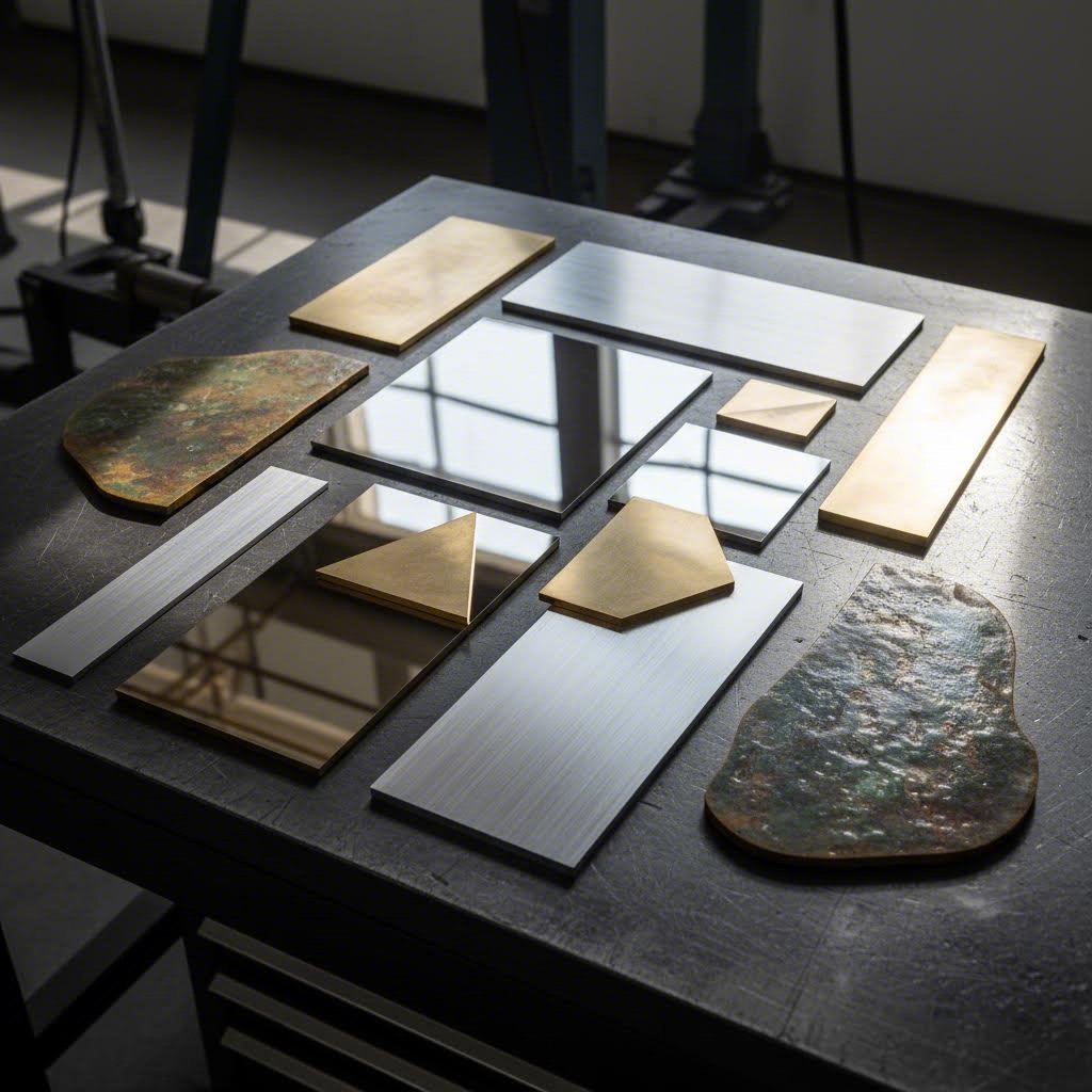
Lazerio pjaustymo detalės yra tikslumo komponentai, pagaminti nukreipiant aukštos galios lazerio spindulį per optiką ir CNC valdymą, kad būtų pjauta, deginama arba garinama medžiaga palei programuotą kelią, taip sukurtos baigtos dalis su aukštos kokybės paviršiumi.
Ši technologija revoliuciją sukėlė pramonėje visose srityse, tačiau terminologija gali būti paini. Panagrinėkime išsamiai, kas tai yra šios komponentės ir kaip jos yra gaminamos.
Kaip lazerio technologija sukuria tikslumo komponentus
Įsivaizduokite, kad saulės šviesa sutelkiama per didinamąją lęšį – dabar padauginkite tą intensyvumą tūkstančiais. Maždaug taip veikia lazerio pjaustymas, nors jo mokslinis pagrindimas yra žymiai sudėtingesnis.
Procesas prasideda tada, kai elektros iškrovos ar lempų skatinamos lazerines medžiagas, esančias uždaroje talpyklėje. Ši energija stiprinama atspindint ją viduje naudojant veidrodžius, kol ji išeina kaip susitelkusios koherentinės šviesos spindulys. Pagal TWI Global , siauriausioje vietoje, lazerio spindulys paprastai yra mažesnis nei 0,32 mm skersmens, o pjūvio plotis gali būti toks pat mažas kaip 0,10 mm, priklausomai nuo medžiagos storio.
Tada susitelkęs spindulys juda CNC programos nustatyta trajektorija per apdirbamą detalę, kur jis:
- Sudegina medžiagą tiksliai nustatytomis temperatūromis
- Išlydo metalą pjovimo linijoje
- Išgarina medžiagą spindulio kelyje
- Išpūtomas pagalbinio dujų srauto, paliekant švarius kraštus
Šis procesas veikia su keliais skirtingais lazerių tipais. Dėl savo 10,6 μm bangos ilgio CO2 lazerinio pjaustymo mašinų dalys ir sistemos puikiai tinka ne metaliniams medžiagoms, tokioms kaip medis, akrilas ir audiniai, apdoroti. Tuo tarpu pluoštinių lazerių pjaustymo mašinų dalys veikia maždaug 1,06 μm bangos ilgyje, kurį metalai sugeria itin gerai – tai juos daro idealiais plienui, aliuminiui ir net atspindintiems metalams, tokiems kaip varis ir bronzos, pjaustyti.
Skirtumas tarp išpjautų detalių ir mašinos dalių
Čia daugelis žmonių susipainioja. Terminas „lazerinio pjaustymo detalės“ apima dvi skirtingas kategorijas:
Lazerinio Pjovimo Detalės (Galutinės Sudedamosios Dalys)
Tai tikrosios per pjovimo procesą sukurtos prekės – tvirtinimo plokštės, korpusai, montavimo plokštės, dekoratyvinės plokštės ir begalė kitų tikslumo komponentų. Kai inžinieriai užsako individualias lazerinio pjaustymo dalis, jie perka galutines arba pusgalutes dalis, pasiruošusias surinkimui ar tolimesniam apdorojimui.
Lazerinio Pjovimo Mašinos Dalys (Įrangos Komponentai)
Tai yra sąnaudų ir keičiamųjų komponentų detalės, kurios užtikrina pjovimo įrangos veikimą. Lazerinio pjovimo mašinos sistemų dalys apima:
- Pjovimo srautukus, kurie nukreipia lazerį ir padedamąjį dujų srautą
- Fokusuojančias lęšius, kurie suskoncentruoja spindulio energiją
- Veidrodžius spindulio išlyginimui ir nukreipimui
- Apsaugos langus, kurie saugo optinius komponentus
- Dujų tiekimo sistemas ir aušinimo įrangą
Šių sąvokų skirtumo supratimas yra svarbus, nes jis veikia viską – nuo tiekėjų paieškos būdo iki projekto reikalavimų perdavimo komunikacijos. Lazerinio pjovimo detalių gamykla gaminama baigtines detalių dalis, o detalių tiekėjas gali specializuotis įrangos sąnaudų prekėse ir keičiamuosiuose elementuose.
Nepriklausomai nuo to, su kuria kategorija dirbate, pagrindiniai principai lieka vienodi visų tipų lazeriams – tikslus spindulio valdymas, medžiagai tinkamos bangos ilgio spinduliuotė ir tinkamo padedamųjų dujų pasirinkimas lemia kiekvieno pjūvio kokybę.
Medžiagų vadovas lazeriu pjovimui skirtoms metalinėms detalėms
Pasirinkus tinkamą medžiagą savo projektui, kuriam reikia lazerinio pjaustymo metalo dalių, tai tarsi pasirenkant ingredientus receptui – netinkamas pasirinkimas gali pažeisti net ir geriausią dizainą. Kiekvienas metalas turi unikalias savybes, kurios veikia pjaustymo kokybę, papildomo apdorojimo reikalavimus ir ilgalaikį našumą. Šių skirtumų supratimas padeda priimti informuotus sprendimus, derinant funkcionalumą, estetiką ir biudžetą.
Ar jūs gaminate lazeriniu būdu pjaustomas lakštines metalo dalis pramoninėms aplikacijoms ar kuriate dekoratyvias lazeriu pjaustomas vario lydinio dalis architektūriniams projektams, pasirinkta medžiaga nulemia viską – nuo pjūvio kraštų kokybės iki korozijos atsparumo.
Metalų medžiagų savybės lazeriniam pjaustymui
Skirtingi metalai skirtingai sąveikauja su lazerine energija. Kai kurie efektyviai sugeria lazerinį šviesą, užtikrindami švarius pjūvius su minimaliomis šilumos paveiktomis zonomis. Kiti – ypač labai atspindintys metalai – kelia unikalius iššūkius, kuriems reikia koreguoti parametrus ir naudoti specializuotą įrangą.
Pagal DP lazeris , pjovimo refleksinių metalų, tokių kaip varis ir aliuminis, iššūkis kyla dėl jų labai atspindinčių paviršių. Metalinis paviršius atspindi lazerio energiją atgal link lazerio šaltinio, o ne sugeria ją pjovimui, dėl ko sumažėja efektyvumas ir gali būti pažeisti optiniai komponentai.
Štai kaip dažni metalai palyginami lazerio pjaustymo taikymuose:
| Medžiaga | Lazerio sugeriamumas | Maksimalus praktinis storis | Pagrindinės savybės | Tipinės taikymo sritys |
|---|---|---|---|---|
| Minkštas plienas (A36/1008) | Puikios | 25 mm+ | Suvirinamas, patvarus, ekonomiškas | Konstrukciniai komponentai, tvirtinimo detalės, rėmai |
| 304 nerūdijančiojo plieno | Labai geras | 20mm | Atsparus korozijai, glotnus paviršius | Virtuvės įranga, statyba, medicina |
| 316 nerūdijantis aiserinis plienas | Labai geras | 20mm | Puikus atsparumas korozijai (jūrinės klasės) | Jūrų, cheminės perdirbimo, farmacijos pramonė |
| 301 Nerūdijantis plienas | Labai geras | 15mm | Didelis tempimo stipris, galintis kietėti dirbant | Spyruoklės, automobilių apdaila, transporterių juostos |
| Aliuminis (5052/6061) | Vidutinis | 12mm | Lengvas, atsparus nuovargiui | Automobiliai, robotika, aviacija |
| Varis (260 serija) | Žemas (atspindintis) | 6mm | Plastinė, nekibirkščiuojanti, dekoratyvi | Įranga, dekoratyviniai elementai, elektra |
| Bronzs | Žemas (atspindintis) | 6mm | Atsparesnis korozijai, mažas trinties koeficientas | Guoliai, įvorės, jūrinė įranga |
| Varis (C110) | Labai žemas (aukščiausiai atspindintis) | 4mm | 99,9 % grynumo, puikus laidumas | Elektros magistralės, sienos dailė, šilumos sklaidytuvai |
Lazeriu pjaunamoms plieno detalėms galimi trys pagrindiniai paviršiaus apdorojimo tipai. Karštai valcuotas plienas tinka konstrukcinėms aplikacijoms, kur estetika mažiau svarbi. Karštai valcuotas rūgščiu plautas ir tepamas (HRP&O) plienas siūlo lygesnį paviršių su apsauga nuo rūdžiavimo. Šaltai valcuotas plienas užtikrina aukščiausią tikslumą ir geriau tinka lenkimui bei gamybai, nors yra brangesnis.
Dirbant su lazeriu pjaunamomis bronzos detalėmis arba vario komponentais, pluoštiniai lazeriai veikia geriau nei CO2 sistemos. Pluoštiniai lazeriai skleidžia 1,07 μm bangos ilgio spindulius – trumpesnius nei CO2 10,6 μm – todėl atspindinčios metalinės medžiagos juos geriau sugeria. Šis didesnis energijos tankis efektyviau prasiskverbia į metalus, greitai juos šildydamas virš jų lydymosi taškų.
Medžiagų pritaikymas prie aplikacijos reikalavimų
Pasirinkdami tarp medžiagų dažnai tenka derinti prieštaraujančius prioritetus. Reikia stiprumo ir ekonomiškumo? Reikia atsparumo korozijai šiurkiomis sąlygomis? Jūsų taikymo reikalavimai turėtų nulemti medžiagos pasirinkimą.
Apsvarstykite skirtumus tarp lazeriu pjaunamų 301 nerūdijančio plieno detalių ir lazeriu pjaunamų 316 nerūdijančio plieno detalių. Pagal Huaxiao Metal , 301 siūlo didesnį tempimo stiprį (515–860 MPa prieš 515–690 MPa 316) ir kainuoja 20–30 % mažiau. Tačiau 316 sudėtyje yra 2–3 % molibdeno, dėl ko jis pasižymi geresniu atsparumu chloridams ir jūros vandeniui.
Štai greitas sprendimų priėmimo pagrindas:
- Jūros ar cheminės aplinkos poveikis: Pasirinkite 316 nerūdijantį plieną – jo molibdenas neleidžia atsirasti duobutinei ir plyšinei korozijai
- Spyruoklės ar aukšto apkrovimo komponentai: Pasirinkite 301 nerūdijantį plieną dėl jo grūdėjimo savybių
- Elektrinė laidumas: Varis ar varinis lydinys užtikrina optimalų našumą
- Svorį jautrios aplikacijos: Aliuminio lydiniai (ypač 5052, 6061 arba 7075) siūlo puikų stiprumo ir svorio santykį
- Kainą atsižvelgiantys konstrukciniai darbai: Minkštasis plienas užtikrina ilgaamžiškumą mažiausia kaina
Lazerinei pjaustyti metalo dalims, kurios apima labai atspindinčias medžiagas, rekomenduojama naudoti azotą kaip pagalbinį dujinį. Pagal DP Laser, pagalbinis dujas padeda išpūsti šlaką, išvalyti pjaustymo plyšį ir aušinti pjovimo zoną. Variniams lakštams, storesniems nei 2 mm, būtina naudoti deguonį, kad medžiaga būtų oksiduota sklandžiam pjaustymui.
Pasirinkus medžiagą, kitas svarbus žingsnis – suprasti projektavimo specifikacijas ir nuokrypius, kurie užtikrina, kad detalės atitiktų matmenų reikalavimus.
Projektavimo specifikacijos ir nuokrypių gairės
Ar kada nors sukūrėte, atrodė, tobulo detalės modelį ekrane, tik kad gautumėte visiškai kitokį rezultatą iš lazerio pjaustyklės? Jūs nesate vienintelis. Tarpas tarp skaitmeninio dizaino ir fizinės tikrovės susidaro dėl tolerancijų, minimalių detalių dydžių supratimo ir vieno svarbaus veiksnio, kurį daugelis dizainerių nepastebi – kerf pločio kompensavimo.
Nesvarbu, ar kuriate tiksliai lazeriu pjaunamas dalis aviacijos pramonei, ar mažas elektronikos dalis, šios specifikacijos lemia, ar jūsų komponentai idealiai sujungs, ar baigsis šiukšlių dėžėje.
Minimalūs elementų dydžiai pagal medžiagos storį
Štai principas, kuris nustebina daugelį naujokų dizainerių: tai, kas veikia CAD, ne visada veikia metale. Lazerio spindulys turi fizinio apribojimus, ir kuo storesnė jūsų medžiaga, tuo labiau šie apribojimai veikia tai, ko galite pasiekti.
Galvokite taip – pjaunama mažytė skylė per ploną lakštinį metalą yra panašu į šiaudelio įsmeigimą į popierių. Dabar įsivaizduokite tą patį šiaudelį įsmeigiant į storą knygą. Fizika keičiasi radikaliai. Kaupiantis šilumai, spindulio sklaidai ir medžiagos išstūmimui kyla daugiau sunkumų, didėjant medžiagos storiui.
Pagal MakerVerse, pjaunamos geometrijos reikėtų atskirti bent du kartus didesniu nei lakšto storis atstumu, kad būtų išvengta iškraipymų. Per arti kraštų esantys skylių padėti gali sukelti plyšimą ar deformaciją, ypač jei detalė vėliau bus formuojama.
Projektuodami tiksliai pjaunamas dalis, naudokite šiuos minimalių elementų nurodymus:
| Funkcijos tipas | Plonas medžiagų stock'as (0,5–2 mm) | Vidutinio storio medžiagų stock'as (3–6 mm) | Storas medžiagų stock'as (8–12 mm) | Storasis medžiagų stock'as (16–25 mm) |
|---|---|---|---|---|
| Mažiausias skylės skersmuo | 1x medžiagos storis | 1x medžiagos storis | 1,2x medžiagos storis | 1,5x medžiagos storis |
| Minimalus plyšio plotis | 1x medžiagos storis | 1,5x medžiagos storis | 2x medžiagos storis | 2,5x medžiagos storis |
| Minimalus teksto aukštis | 2 mm | 3 mm | 5mm | 8mm |
| Atstumas nuo krašto iki skylės | 2x medžiagos storis | 2x medžiagos storis | 2,5x medžiagos storis | 3x medžiagos storis |
| Detalių tarpusavio atstumas | 2x medžiagos storis | 2x medžiagos storis | 2x medžiagos storis | 2x medžiagos storis |
Projektuojant individualius tikslumo lazerio pjaustomus nerūdijančio plieno dalių elementus, ypatingą dėmesį reikia skirti šilumos kaupimuisi. Nerūdijantis plienas prastai varo šilumą lyginant su minkštu plienu ar aliuminiu, todėl arti esančios detalės gali sukelti šiluminį iškraipymą. Papildomas atstumas tarp sudėtingų detalių padeda sumažinti šilumą ir išlaikyti matmeninį tikslumą.
Atskiroms atplėštoms ir tilteliams – mažiems sujungimams, kurie pjaustymo metu laiko dalis vietoje – rekomenduojama naudoti plotį nuo 0,5 mm iki 2 mm, priklausomai nuo detalės svorio ir medžiagos. Per siauri linkę lūžti apdorojimo metu. Per stori reikalauja pernelyg didelio papildomo apdorojimo, kad būtų galima juos švariai pašalinti.
Pjaustymo plyšio kompensavimo supratimas
Pjaustymo plyšys – tai medžiaga, kurią pašalina pats pjaustymo procesas. Skamba paprastai, tiesa? Tačiau čia ir slypi tikslumo prie lazerio pjaustyme įdomumo pusė – ir būtent čia daugelis projektų nepavyksta.
Pagal MakerVerse, kerf pločio diapazonas paprastai yra nuo 0,1 mm iki 1,0 mm, priklausomai nuo medžiagos ir pjovimo parametrų. Šis skirtumas reiškia, kad 50 mm skylė, suprojektuota be kompensacijos, galiausiai gali matuoti nuo 50,2 mm iki 51 mm pagamintoje detalėje.
Kompensacijos apskaičiavimas yra paprastas: perkelti pjovimo kelią per pusę kerf pločio. Išoriniams pjūviams (detalės kontūrui) perkelti į išorę. Vidiniams pjūviams (skylėms ir kišenėms) – į vidų. Dauguma CAM programinės įrangos tai atlieka automatiškai – bet tik tuo atveju, jei įvedate teisingą kerf reikšmę.
Palyginamieji duomenys iš Torchmate pateikia specifines kerf kompensacijos reikšmes, priklausomai nuo medžiagų ir storio:
| Medžiaga | Storis | FineCut kerf (mm) | Standartinis 45A kerf (mm) | Sunkusis 85A kerf (mm) |
|---|---|---|---|---|
| Mild steel | 1mm | 0.7 | 1.1 | — |
| Mild steel | 3 mm | 0.6 | 1.5 | 1.7 |
| Mild steel | 6mm | — | 1.7 | 1.8 |
| Mild steel | 12mm | — | — | 2.2 |
| Nerūdijantis plienas | 1mm | 0.5 | 1.1 | — |
| Nerūdijantis plienas | 3 mm | 0.5 | 1.6 | 1.6 |
| Nerūdijantis plienas | 6mm | — | 1.8 | 1.8 |
| Aliuminio | 3 mm | — | 1.6 | 2.0 |
| Aliuminio | 6mm | — | 1.5 | 1.9 |
Pastebėkite, kaip kerfo plotis didėja kartu su medžiagos storiu ir amperažu? Ši priklausomybė paaiškina, kodėl metalo tikslumo detalių laseriniam pjaustymui reikia skirtingų kompensacijos verčių, atsižvelgiant į skirtingus gamybos nustatymus. Visada patvirtinkite savo tiekėjo nurodytas specifines kerfo vertes, o ne remkitės bendraisiais įvertinimais.
Priežasties ir pasekmės ryšys čia yra tiesioginis: jei nepakankamai kompensuojate, jūsų detalės bus per didelės. Jei per daug kompensuojate – jos bus per mažos. Sujungiamoms detalėms – pavyzdžiui, atplaišoms, turinčioms tilpti į plyšius – abi detalės turi būti tinkamai kompensuotos, kitaip jų nebus galima tinkamai surinkti.
Projektuodami sujungimo taškus, atsižvelkite tiek į kerfą, tiek į natūralų siaurėjimą storesnėse medžiagose. Laseriniai spinduliai šiek tiek išsisklaido praeidami per metalą, todėl pjūviai viršuje būna šiek tiek platesni nei apačioje. Tikslaus surinkimo detalėms aptarkite su gamintoju siaurėjimo kompensavimą.
Kai jūsų projekto specifikacijos jau nustatytos, kitas žingsnis – rengti failus, kurie tiksliai perduotų šiuos reikalavimus pjaustymo sistemai.
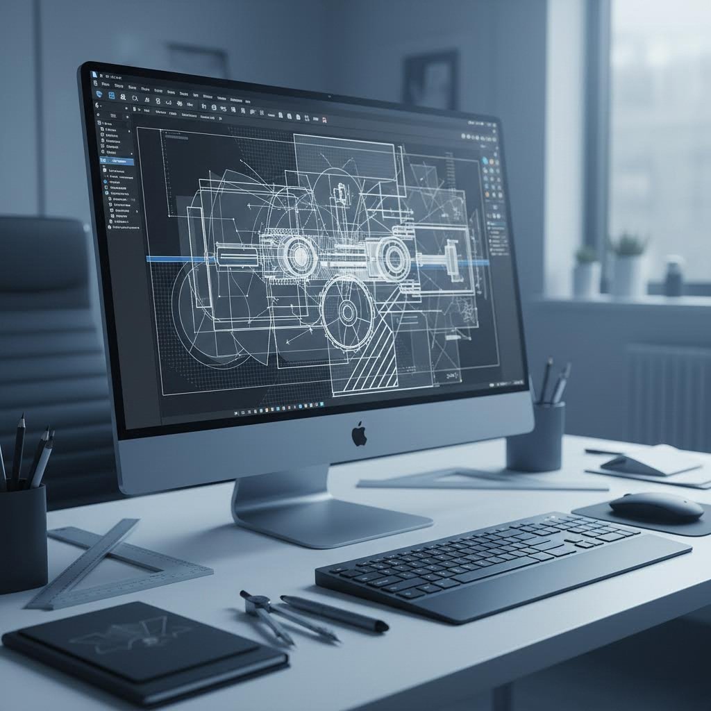
Failų paruošimas ir vektorinės grafikos pagrindai
Jūs puikiai susitvarkėte su projekto specifikacijomis. Jūsų tolerancijos popieriuje yra tobulos. Tačiau štai kokia nusivylimą kelianti realybė – pateikus netinkamą failo formatą ar praleidus paprastą nustatymą, jūsų tikslus darbas gali tapti gamybos problema. Būtent failų paruošimo etape daugelis individualių lazerio pjaustymo detalių projektų susiduria su sunkumais, ne dėl sudėtingų techninių reikalavimų, o dėl lengvai išvengiamų klaidų.
Gera naujiena ta, kad supratus, ko iš jūsų failų iš tikrųjų reikia lazerio pjaustymo sistemoms, paruošimas tampa paprastu procesu. Peržvelkime visą darbo eigą nuo projekto idėjos iki lazeriu pjaustyti paruoštų failų.
Vektorinių failų reikalavimai švariems pjaustymams
Lazerio pjaustymo mašinos seka takus – matematines linijas ir kreives, kurios tiksliai nurodo pjovimo galvutei, kur judėti. Dėl šios priežasties vektoriniai failai yra būtini. Skirtingai nei rastriniai vaizdai (JPEG, PNG), kuriuose saugoma pikselių informacija, vektoriniai failai turi geometrines lygtis, kurios gali būti mastelio keičiamos be jokios tikslumo netekties.
Pagal Xometry, DXF (brėžinių keitimo formatas) yra 1982 m. sukurtas vektorinis failo tipas kaip pirmosios AutoCAD versijos dalis. Kadangi DXF yra atviro kodo, jis veikia praktiškai su visomis CAD ir lazerio pjaustymo programinėmis įrangomis – todėl tai universalus kalbos standartas projektuojant lazeriu pjaustomas dalis.
Štai kaip palyginami dažniausi failų formatai:
- .DXF (brėžinių keitimo formatas): Visuotinai suderinamas variantas. Veikia su beveik visomis CAD programomis ir lazerio pjaustymo programinėmis įrangomis. Idealus bendrinant failus tarp skirtingų sistemų ar tiekėjų.
- .DWG (AutoCAD brėžinys): AutoCAD gimtinis formatas, turintis daugiau funkcijų nei DXF, tačiau yra nuosavybės teisių apsaugotas. Geriausias, kai dirbama visiškai Autodesk ekosistemoje.
- .AI (Adobe Illustrator): Puikiai tinka iliustracijų kūrimui „Illustrator“. Pagal SendCutSend , natyvūs .ai failai išsaugo visas „Illustrator“ specifines priemones ir funkcijas, kurios galbūt negali būti teisingai eksportuojamos į .dxf ar .eps formatus.
- .SVG (Scalable Vector Graphics): Lanksti, tinkama naudoti internete formatas, suderinamas su daugeliu dizaino programų. Puikus paprastesniems dizainams ir bendrinimui tarp platformų.
Pagrindinis reikalavimas visiems formatams? Kiekvienas takas turi būti tikras vektorius. Pagal SendCutSend, vektoriniai takai reiškia matematinį tobulumą – tai lygčių serija, nusakančia patį taką. Tai reiškia, kad jie visiškai nepriklauso nuo mastelio, skirtingai nei rastriniai failai, turintys apibrėžtas raiškos ribas.
Ruošiant individualius CNC lazerio pjaustymo detalių brėžinius, atkreipkite dėmesį, kaip savo faile skiriatės pjaustymo tipus. Pagal Fabberz, standartinė praktika naudoja tam tikrus spalvų ir braižo storio derinius:
- Pjovimo linijos: RGB raudona (255, 0, 0) su 0,001 colio braižu – pilnai perpjaustyti kontūrai
- Brėžimo linijos: RGB mėlyna (0, 0, 255) su 0,001 colio braižu – dalinio gylio graviravimas
- Rasterinis graviravimas: Juodos arba pilkos spalvos užpildai – paviršiaus graviravimui
Programinės įrangos nustatymas dizainams, paruoštiems lazerinei apdailai
Jūsų pasirinkta programinė įranga svarbi mažiau nei tai, kaip ją sukonfigūruojate. Ar naudojate Adobe Illustrator, AutoCAD, Fusion 360, Inkscape ar Rhino 3D – tam tikri nustatymai yra privalomi, kad lazeriniai pjaunantys būtų švarūs.
Pagal SendCutSend, pirmas žingsnis „Illustrator“ yra matavimo vienetų nustatymas coliais ar milimetrais. Tai užtikrina, kad jūsų failas tinkamai išsiskleis, kai bus įkeltas į lazerinio pjaustymo programinę įrangą. Jūsų piešimo plotas turėtų būti šiek tiek didesnis už galutinius detalės matmenis.
Čia daugelis dizainerių padaro klaidą: naudoja kontūrus vietoj užpildymų. Kai objektą kuriate naudodami kontūrą, sistema mato du kontūrus – numatytą kraštą ir paties kontūro išorinį rėmą. Projektuokite savo objektus kaip užpildymus, kad išvengtumėte dvigubo kelio problemos.
Teksto elementams visada prieš eksportuojant juos versti į apibrėžimus. „Illustrator“ pasirinkite savo tekstą ir naudokite Tekstas → Sukurti apibrėžimus (Shift + Cmd/Ctrl + O). Tai pašalina šriftų suderinamumo problemas ir užtikrina, kad jūsų tipografika būtų išpjauta tiksliai pagal projektą.
Viena galinga įpročio forma? Reguliariai tikrinkite darbą Apibrėžimo režime. Pagal SendCutSend, Apibrėžimo režimas kiekvieną kelią rodo kaip pilnus kelius, parodydamas sankirtas, persidengimus ir trūkstamas jungtis, kurios normaliuose rodinys yra nematomos.
Prieš pateikdami failus, peržiūrėkite šį būtiną kontrolinį sąrašą:
- Visi keliai yra uždaryti – nėra atvirų kontūrų ar tarpų formose
- Tekstas pervestas į apibrėžimus/kreives
- Nėra dubliuotų ar persidengiančių linijų (naudokite Jungti „Illustrator“, SelDup „Rhino“ arba Overkill „AutoCAD“)
- Objektai suprojektuoti kaip užpildai, o ne braižiniai
- Visi elementai viename sluoksnyje
- Paslėpti sluoksniai, apkarpymo kaukės ir atsitiktiniai taškai pašalinti
- Dokumento dydis atitinka medžiagos matmenis
- Vienetai nustatyti teisingai (coliai arba milimetrai)
- Mažiausiai 0,25 colio paraštė aplink piešinį kaip perpildymo zona
- Detalės išdėstytos su mažiausiai 0,125 colio atstumu tarp objektų
Pagal Fabberz , persidengiantys brėžiniai sukelia pernelyg didelį degimą arba nereikalingus pjovimo praėjimus. Prieš pateikiant failą, verta skirti laiko kelių sujungimui ir pasikartojančių elementų pašalinimui, kad nebūtų gadinamos medžiagos ir nekiltų gamybos delsimų.
Turėdami tinkamai paruoštus failus, jau galite nagrinėti, kaip šios tiksliai supjautos detalės tarnauja reiklioms pramonės šakoms, kur kokybė nėra pasirinkimas – ji yra gyvybiškai svarbi.

Pramonės taikymai nuo automobilių iki aviacijos
Kai vartotojo prekėje sugenda detalė, jūs galite susidurti su nepatogiu grąžinimu. O kai lėktuve 35 000 pėdų aukštyje ar kareiviniame vežime ugnies užtambaryje sugenda komponentas? Rizika negali būti didesnė. Dėl to tikslus lazerinis pjaustymas tapo nepakeičiamu pramonės šakose, kur klaidų riba praktiškai lygi nuliui.
Nuo automobilių dalių, išpjautų lazeriu ir apsaugančių keleivius susidūrimo metu, iki aviacijos pramonės dalių, išpjautų lazeriu ir atlaikančių kraštutinius temperatūros svyravimus, šios technologijos gebėjimas gaminti be defektų komponentus dideliais kiekiais daro ją pagrindiniu pasirinkimu reikliausioms pasaulio taikymo sritims.
Automobilių rėmai ir konstrukciniai komponentai
Apsilankę bet kurioje šiuolaikinėje automobilių surinkimo gamykloje, rasite, kad beveik kiekviename etape naudojamas lazerio pjaustymas automobilių dalims. Šios technologijos greitis, tikslumas ir kartojamumas puikiai tinka pramonei, kur reikalinga didelė gamybos apimtis ir mažos leistinos nuokrypos.
Pagal Didžiųjų ežerų inžinerija , gamintojai naudoja tikslią lazerio pjaustymo technologiją šassi detalėms, karoserijos plokštėms, variklio komponentams ir sudėtingiems sujungimams gaminti iš metalų, tokių kaip plienas ir aliuminis. Proceso didelis greitis ir tikslumas leidžia greitai gaminti detales, atitinkančias mažas leistinas nuokrypas, todėl palaikoma pramonės reikmė efektyviai ir didelės apimties gamybai.
Kokie dažniausiai gaminami OEM dalys, išpjaunamos lazeriu, naudojamos automobilių pramonėje?
- Korpuso komponentai: Rėmo bėgiai, skersiniai ir pagrindinio rėmo surinkimo detalės, kurios sudaro transporto priemonės konstrukcinį pagrindą
- Pakabos tvirtinimo elementai: Valdymo svirties tvirtinimai, amortizatorių bokštai ir stabilizatoriaus strypo jungtys, reikalaujančios tikslaus varžtų išdėstymo
- Korpuso stiprinimai: Durų įsisunkimo sijos, stogo horizontalės ir A/B/C stulpelių stiprinimai smūgiui apsaugoti
- Šilumos skydai: Išmetimo sistemos apsaugos ir apačios šiluminės barjerai iš nerūdijančio plieno ar aliuminio
- Tvankos plokštės: Variklio tvirtinimo lankstai, pavarų dėžės atramos ir aksesuarų montavimo paviršiai
- Vidinės konstrukcinės detalės: Sėdynių rėmai, prietaisų skydelio atramos ir konsolės tvirtinimo lankstai
Sumažėjęs detalės iškraipymas ir minimalus poreikis po apdorojimui ženkliai padidina produktyvumą. Gamindami tūkstančius identiškų lankstų kasdien, net nedidelės efektyvumo prieaugio naudą susideda į didelius sąnaudų taupymus.
Lazerinei pjaustybai skirtų OEM dalių atveju kokybės sertifikatai nėra pasirinktinas dalykas – jie yra būtinos sutarties sąlygos. IATF 16949 sertifikatas parodo gamintojo įsipareigojimą laikytis automobilių pramonei būtinos kokybės valdymo sistemos, kurios reikalauja didžiosios OEM kompanijos iš tiekimo grandinės. Šis sertifikavimas grindžiamas ISO 9001 pagrindais, tačiau papildytas automobilių pramonei būdingomis reikalovėmis, skirtomis defektų prevencijai ir kintamumo mažinimui.
Kosmoso ir gynybos taikymai
Jei automobilių tarpiniai matmenys atrodo reikalaujantys, aviacijoje tikslumas pakeliamas visiškai į kitą lygį. Detalė, kuri yra priimtina žemėje naudojamams transporto priemonėms, gali katastrofiškai sugesti veikiant aukščio sukeliamiems temperatūros svyravimams, vibracijos dažniams bei slėgio skirtumams, kuriuos tenka patirti skrydyje.
Pagal Great Lakes Engineering, tikslusis lazerinis pjaustymas plačiai naudojamas sudėtingoms detalėms, tokioms kaip tvirtinimo skliaustai, montavimo plokštės ir konstrukciniai elementai, gaminti iš medžiagų, tokių kaip nerūdijantis plienas ir titanas. Šios technologijos gebėjimas daryti švarius pjūvius su minimaliomis šilumos paveiktomis zonomis užtikrina, kad detalės išlaikytų savo vientisumą ekstremaliomis sąlygomis, pvz., didelėse aukštybėse ir temperatūros svyravimų metu.
Lazeriu pjaustomos aviacijos detalės dažnai apima:
- Konstrukciniai laikikliai: Variklių tvirtinimo įtaisus, važiuoklės tvirtinimus ir sparnų rėmelio jungtis
- Avionikos korpusai: Prietaisų skydo korpusus, radarinių komponentų dėžutes ir ryšių įrangos blokus
- Šilumos valdymo komponentai: Šilumokaičius, aušinimo kanalų plokštes ir šiluminės izoliacijos skliaustus
- Vidinė apdaila: Sėdynių bėgelius, viršutinių sandėliukų atramas ir galinės dalies (galley) tvirtinimo įrangą
- Valdymo paviršių elementai: Pavarų tvirtinimus, vyrių skliaustus ir žiedų reguliavimo jungtis
Lazerinis karinių detalių pjaustymas reikalauja dar griežtesnių protokolų. Pagal Rache Corporation , ITAR (Tarptautinės ginklų prekybos reglamentavimo taisyklės) sertifikatas parodo laikymąsi griežtų taisyklių, reguliuojančių gynybos medžiagų ir paslaugų importą bei eksportą. Gamintojai, gaminantys laseriu pjaunamus karinius komponentus, privalo tvarkyti kruopščią dokumentaciją, taikyti prieigos kontrolę ir saugumo priemones – NIST 800-171 atitiktis tapo būtina valdant kontroliuojamą neklasifikuotą informaciją.
AS9100 sertifikatas atstovauja aukso standartą aviacijos kokybės valdyme. Šis visame pasaulyje pripažintas standartas užtikrina, kad gamintojai nuosekliai galėtų teikti produktus ir paslaugas, atitinkančius aviacijos ir kosmoso taikymo sričių išskirtinės kokybės reikalavimus.
Kaip iš tikrųjų atrodo kelias nuo sumanymo iki gamybos šiose labai svarbiose pramonės šakose? Jis paprastai vyksta tokia tvarka:
- Projekto pateikimas: Inžinerijos komandos pateikia CAD failus su visomis specifikacijomis ir medžiagų nurodymais
- DFM peržiūra: Gamintojų inžinieriai analizuoja konstrukcijas dėl gamybos galimybės, siūlydami optimizavimus, kurie sumažina sąnaudas, nesumažindami funkcionalumo
- Prototipo gamyba: Mažos partijos bandymai patvirtina atitiktį, formą ir funkciją prieš pradedant gamybos įrankių gamybą
- Pirmosios partijos patikra: Visapusi matmenų tikrinimas užtikrina, kad detalės atitiktų visus brėžinių reikalavimus
- Gaminių gamybos patvirtinimas: Kliento patvirtinimas inicijuoja pilno masto gamybą
- Tolydinė kokybės kontrolė: Statistinis proceso valdymas ir periodinės apžvalgos užtikrina nuoseklumą visose gamybos partijose
Automobilių ir aviacijos gamintojams, siekiantiems pagreitinti šį procesą, bendradarbiaujant su IATF 16949 sertifikuotais tiekėjais, kurie siūlo greitą prototipavimą ir išsamią DFM paramą, galima ženkliai sutrumpinti plėtros laikotarpius. Shaoyi (Ningbo) Metal Technology pavyzdžiu gali būti toks požiūris, siūlant 5 dienų greitą prototipavimą ir 12 valandų pasiūlymų pateikimo terminą šassi, pakabos ir konstrukciniams komponentams.
Ar jūs gaminate automobilių detales, pjaunamas lazeriu, kitiems metams skirtai transporto priemonių platformai, ar lazeriu pjaunamas karinės technikos dalis gynybos sutartims, tiekimo partneris turi parodyti tiek techninį pajėgumą, tiek atitiktį sertifikavimo reikalavimams. Kokybės trūkumų pasekmės šiose srityse siekia toliau nei garantiniai reikalavimai – jos apima saugumą, saugą ir žmonių gyvybes.
Žinoma, net idealiai išpjautos detalės reikalauja apdailos operacijų, prieš tai, kol jos bus paruošiamos surinkimui. Apdorojimo po pjovimo reikalavimų supratimas užtikrina, kad jūsų komponentai atitiktų galutinius specifikacijų reikalavimus.
Apdorojimas po pjovimo ir užburkšnijimo šalinimo metodai
Jūsų detalės buvo nuimtos nuo lazerinio pjovimo staklių aštrios – tiesiogine prasme. Tie tikslūs kraštai, kurie daro lazerinį pjaustymą tokį vertingą, taip pat sukuria problemą: užburkšnijimą, aštrius kampus ir likutinį lydymą, kurie gali perplėšti pirštus, trukdyti tinkamam surinkimui ir sugadinti dangos sukibimą. Lazerinių detalių užburkšnijimo šalinimas nėra pasirinkimas. Tai būtinybė saugumui, našumui ir sekantiems apdorojimo etapams.
Pagal Evotec Group , tinkamas užuolaidų pašalinimas ir apdaila užtikrina galutinių produktų saugą, kokybę, gamybos patogumą, paruoštumą dengti ir patikimumą. Klausimas nėra tas, ar šalinti užuolas iš lazeriu pjaunamų detalių – svarbu, kuris metodas atitinka jūsų specifinius reikalavimus.
Detalių užuolaidų šalinimo metodai skirtingų tipų detalėms
Ne visos užuolaidos yra vienodos, taip pat ir nevienodi yra užuolaidų šalinimo sprendimai. Išlydyta pjovimo kraštinė, likusi pjovus aliuminį, elgiasi kitaip nei oksidų sluoksnis ant minkštojo plieno arba atkaklus drumzlės sluoksnis ant storos nerūdijančios plieno. Suprantant turimas galimybes, galima pasirinkti tinkamiausią metodą pagal jūsų gamybos apimtis, detalių geometriją ir paviršiaus apdailos reikalavimus.
Rankinis kirtimų šalinimas
Naudojant rėžtukus, smalinį popierių, rankinius šlifavimo įrenginius arba abrazyvines plokšteles, rankinis užuolaidų šalinimas siūlo lankstumą mažoms partijoms ar sudėtingos geometrijos detalėms, kur automatiniai metodai nepasiekia. Tai ekonomiškai naudinga prototipams ir vienetinėms detalėms. Tačiau trūkumai yra dideli: nevienodi rezultatai, lėtas apdorojimas ir galimybė padaryti žmogišką klaidą ar sužeisti.
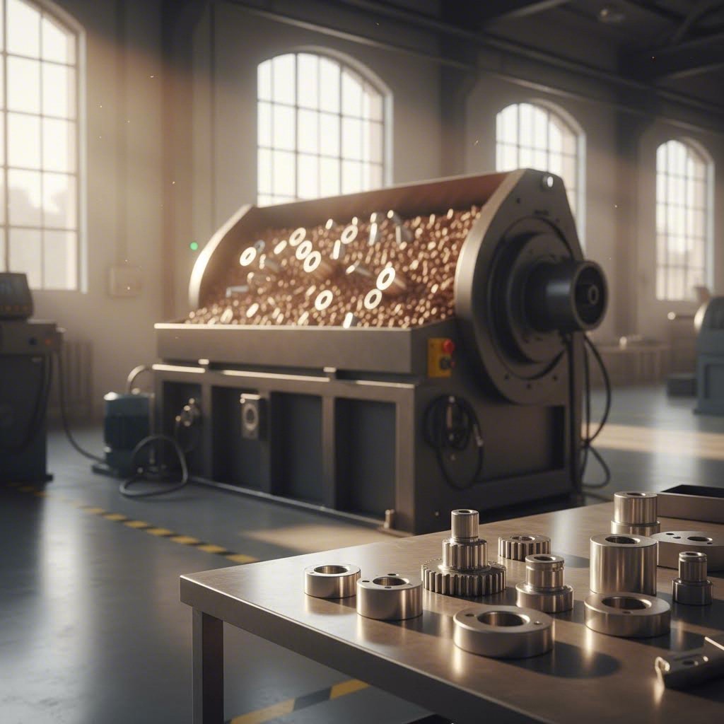
Apvartymo ir virpamoji apdaila
Detalės kartu su abrazyvine medžiaga patenka į besisukantį barą arba vibracinį baką. Tarpusavio trintis ir smūgiai tarp medžiagos ir detalių pašalina užkorus ir suapvalina kraštus. Šis metodas leidžia vienu metu apdoroti daug detalių pastoviais rezultatais – tai puikus variantas mažų lazeriu pjaunamų detalių užkorų šalinimui partijomis. Lazeriu pjaunamoms aliuminio detalėms užkorų šalinimui keraminė arba plastikinė medžiaga apsaugo paviršių nuo pažeidimų, efektyviai šalindama užkorus.
Platjuosčiai ir šepečiai
Plokščiam metalui ir stambesnėms detalėms platjuosčiai aparatai paduoda dalis po abrazyvinėmis juostomis, kurios apdoroja kraštus ir paviršius. Besisukančios šepetų sistemos – naudojančios vielinius, niloninius arba abrazyvinius elementus – liečiasi su detalių kraštais, kad pašalintų užkorus, suapvalintų kampus ir nuvalytų oksido likučius. Toks lazeriu pjaunamų detalių užkorų šalinimo aparatas užtikrina didelį našumą, kurio rankinis būdas negali pasiekti.
Lazerinis užkorų šalinimas
Pag according to Evotec grupės, šis kylantis metodas naudoja aukštos energijos suskoncentruotą lazerio spindulį, kad ištirpintų arba išgarintų iškilimus, kartais perlydant metalą, kad būtų suformuotos apvalios, be defektų kraštinės. Jis ypač naudingas sudėtingoms formoms ir aukštos tikslumo detalėms, kur mechaninis įtempis, kylančias iš tradicinių metodų, gali sukelti problemas.
| Metodas | Tinkamiausias | Detalės dydis | Tūris | Privalumai | Trūkumai |
|---|---|---|---|---|---|
| Rankinis (failai, šlifavimo įrankiai) | Prototipai, sudėtingos geometrijos | Bet koks | Žemi | Žema kaina, lankstumas, tikslus valdymas | Lėtas, nestabilus, sužalojimų rizika |
| Šukavimas / virpesių | Mažos–vidutinės detalės, partijos | Mažos–vidutinės | Vidutinis-Aukštas | Apdoroja vidines kraštines, nuoseklus | Netinka didelėms plokščioms detalėms, ilgesni ciklai |
| Platjuostis mašina | Lakštinis metalas, plokšti komponentai | Vidutinis-Didelis | Aukšto | Greitas, tolygus paviršiaus apdorojimas | Apribotas plokščioms geometrijoms |
| Rotuojanti šepetėlė | Briaunų suapvalinimas, oksidų šalinimas | Mažas-Didelis | Vidutinis-Aukštas | Universalus, gera briaunų kokybė | Gali nepasiekti gilių įdubų |
| Lazerinis užkorų šalinimas | Sudėtingos formos, tikslūs komponentai | Mažos–vidutinės | Žema-vidutinė | Didelis tikslumas, minimalus įtempimas | Brangi įranga, ribotas našumas |
Šiuolaikinės gamybos dirbtuvės dažnai derina skirtingas metodus. Tipiškas darbo eigas gali sudaryti rotacinio šepetėlio kraštų suapvalinimas, po to pločioju juostiniu slifuokliu paviršiaus apdorojimas ir galutinis vibrolakštavimas – kiekvienas etapas tenkina skirtingus lazerinio pjaustymo metalinių detalių deflekavimo reikalavimus.
Kokybės patikros ir verifikavimo etapai
Prieš išeinant dalims iš dirbtuvės, kaip jūs žinote, kad jos iš tikrųjų yra gerų kokybių? Vizuali patikra aptinka akivaizdžias problemas, tačiau sisteminga kokybės verifikacija neleidžia subtiliems trūkumams, kurie vėliau gali sukelti surinkimo gedimus ar ankstyvą susidėvėjimą.
Pagal Halden CN, būdingi lazerinio pjaustymo defektai apima burkus, drusas, išlinkimus ir degimo žymes. Šios problemos gali sukelti šiurkščius kraštus, netikslius pjaustymo kontūrus ir pažeistus paviršius, dėl ko blogėja galutinio produkto kokybė.
Šilumos paveiktos zonos (HAZ)
Lazerio intensyvus karštis sukuria siaurą zoną, kurioje keičiamos medžiagos savybės. Pliene tai pasireiškia spalvos pakeitimu – nuo šiaudinės geltonos iki mėlynai violetinės. Per didelė šilumos poveikio zona (HAZ) rodo, kad reikia sureguliuoti pjovimo parametrus – dažniausiai sumažinti greitį arba padidinti galios lygį virš optimalaus. Kritinėse aplikacijose HAZ pločio matavimai ir dokumentavimas yra būtini.
Droso susidarymas
Šlakas – tai užšalusios lydytos medžiagos likučiai, prilipę pjaustymo krašto apačioje. Halden CN teigia, kad per daug šlako kyla dėl netinkamo pagalbinės dujų srauto, neteisingos fokusuotės pozicijos arba per lėto pjovimo greičio. Švelnus šlakas gali būti leistinas nekritinėse aplikacijose, tačiau stiprus šlakas reikalauja pakartotinio pjovimo arba išsamios po-pjovimo apdorojimo.
Matmenų tikslumas
Patikrinkite kritinius matmenis pagal brėžinio specifikacijas naudodami kalibruotus prietaisus. Patikrinkite skylų skersmenis, įpjovų pločius ir bendrus detalės matmenis. Tiksliajam darbui palyginkite kelias tos pačios partijos dalis, kad nustatytumėte kitimo tendencijas, kurios gali rodyti į įrangos nukrypimą.
Saugumo sumetimai
Skirtingi medžiagų apdorojimo laikas šlifavimo metu kyla skirtingos pavojai. Aliuminis sukuria smulkius dalelių, kurios gali pakliūti į orą – būtinas tinkamas vėdinimas ir dulkių surinkimas. Nerūdijantis plienas ir cinkuotos medžiagos šiluminių procesų metu gali išskirti nuodingas garus. Visada naudokite tinkamus asmeninės apsaugos priemones ir užtikrinkite tinkamą vėdinimą, ypač apdorojant dengtas arba apdorotas metalo rūšis.
Kokybės problemas nustatant anksti – prieš siunčiant dalis ar joms patekant į surinkimą – sutaupoma laiko, pinigų ir klientų santykių. Tačiau kas nutinka, kai problemos vis dėlto kyla? Priežasčių supratimas padeda išvengti kartojimosi.
Dažniausių lazerio pjovimo problemų šalinimas
Jūsų detalės grįžo iš pjovimo, bet kažkas ne taip. Galbūt kraštai yra grubūs, tada, kai turėtų būti lygūs. Galbūt skylių, kurios turėtų tikt lentynos varžtams, keistai mažesnės. Galbūt kai kurie pjūviai nebuvo visiškai prapjauti. Prieš kaltinti įrangą ar operatorių, pagalvokite apie tai: dauguma lazerio pjaustymo problemų kyla dėl numanomų priežasčių, kurioms egzistuoja paprasti sprendimai.
Pagal ADH Machine Tool, laiku atpažinti ir išspręsti dažnai pasitaikančias problemas, susijusias su lazeriniu pjovimu, yra lemtinga užtikrinant sklandų gamybos procesą ir gerinant gaminio kokybę. Supratimas apie simptomų ir šakninių priežasčių sąsają transformuoja erzinančius gedimus į išsprendžiamas problemas.
Dažnos pjovimo problemos ir jų šakninės priežastys
Įsivaizduokite klaidų šalinimą kaip detektyvinį darbą. Simptomas rodo, kad kažkas nutiko neteisingai. Priežastis paaiškina, kodėl taip įvyko. O sprendimas neleidžia tai pasikartoti. Žemiau pateikta sisteminga analizė dažniausiai pasitaikančių problemų:
| Problema | Dažninos priežastys | Sprendimai |
|---|---|---|
| Nevisiškas pjūvis (lazeris neperskverbia visiškai) | Medžiaga per storesnė nei leidžia nustatytieji galios parametrai; pjovimo greitis per didelis; fokusavimas nesutvarkytas; nusidėvėjęs žarnos galas arba užteršta lęšis | Sumažinkite greitį arba padidinkite galios nustatymus; patikrinkite medžiagos storio ribas; pakartotinai sureguliuokite optiką; patikrinkite ir pakeiskite nusidėvėjusias CNC lazerinio pjovimo staklių dalis |
| Per didelis kraštų sukibimas arba šlakas | Pjovimo greitis per lėtas; pagalbinės dujos netinkamo slėgio; nusidėvėjęs antgalis sukuria netolygų dujų srautą; fokusavimo padėtis neteisinga | Padidinkite pjovimo greitį; sureguliuokite dujų slėgį (paprastai aukštesnis gaunant švaresniems kraštams); pakeiskite pažeistus antgalius; perkoreguokite židinio padėtį |
| Iškraipymas arba išlinkimas | Per didelis šilumos kaupimasis; medžiaga netinkamai pritvirtinta; per arti vienas kito esantys pjovimo elementai; viena stipri apkrova vietoj kelių lengvesnių eilių | Sumažinkite galingumą ir padidinkite greitį; naudokite laikiklius ar svorius; padidinkite atstumą tarp elementų; pjauskite kelis kartus mažesniu galingumu |
| Matmenų netikslumas | Neteisingas kerf kompensavimas; pernelyg atsipalaidavę diržai ar mechaniniai komponentai; šiluminis plėtimasis; kalibravimo paslydimas | Patikrinkite ir sureguliuokite kerf nustatymus; užveržkite diržus ir patikrinkite skriemules; leiskite įrenginiui įšilti prieš tikslų darbą; reguliariai atlikite kalibravimą |
| Šiurkštūs arba lakštai kraštai | Nešvarios optika arba lęšiai; neteisingas fokusas; netinkamos rūšies dujos; spindulio netolygių nustatymas | Reguliariai valykite veidrodžius ir lęšius; prieš pjovimą iš naujo nustatykite lazerio fokusą; perjunkite į azotą, kad metalo kraštai būtų lygesni; pakartotinai sureguliuokite spindulio kelią |
| Degimo žymės arba apdegimai | Per didelė lazerio galia; pjovimo greitis per lėtas; nepakankamas oro padėjimas | Sumažinkite galią; padidinkite greitį; užtikrinkite tinkamą oro padėjimą, kad dūmai ir šiluma būtų nuvalyti |
| Nevienodas pjovimo kokybė visame darbo lauke | Nelygi medžiagos paviršius; darbo stalas nelygus; spindulio išsisklaidymas dėl optinių problemų | Užtikrinkite, kad medžiaga gulėtų plokščiai; išlyginkite pjovimo stalą; patikrinkite visus optinius komponentus dėl pažeidimų ar užterštumo |
Pagal American Laser Co , kai lazeris tiksliai nepraeina numatyta kryptimi, dažniausiai tai sukelia atlaisvinti diržai, atlaisvinti mechaniniai komponentai arba kalibravimo poslinkis. Sprendimai – diržų priveržimas, mašinos mechanikos tikrinimas bei reguliarus kalibravimas ir techninė priežiūra.
Kaip diagnozuoti problemas, kol jos nesunaikino visos gamybos eigos? Pradėkite nuo bandomųjų pjūvių ant atliekų medžiagos. Paprastas kvadratas ar apskritimas parodys sutapimo problemas, matmenų tikslumą ir kraštų kokybę dar prieš naudodami vertingą žaliavą. Po pjovimo apžiūrėkite abi paviršiaus puses – drosas dažniausiai kaupiasi apačioje, o degimo žymės matomos viršuje.
Klausykite savo įrenginio. Pagal ADH Machine Tool, bet koks nestandartinis garsas ar virpėjimas įrenginio judėjimo metu yra įrangos mechaninės ar elektrinės sistemos skleidžiamas bėdos signalas. Skirtingi garsai rodo skirtingas problemas – trankus garsas reiškia guolių susidėvėjimą, cyptelėjimas rodo diržo problemas, o netaisyklingas pulsavimas gali rodyti maitinimo šaltinio problemas.
Konstrukcijos sprendimai, kurie neleidžia kilstanti problemoms gamyboje
Daugelis pjovimo problemų iš tiesų nėra įrangos gedimai – tai konstrukciniai sprendimai, kurie iš anksto nulemia gamybos nesėkmę. Štai keletas pakeitimų, kuriuos atlikus iki pjovimo, galima išvengti bėdų vėliau:
Detalių išdėstymas
Kai skylės, plyšiai ar išpjovos yra per arti viena kitos, šiluma kaupiasi greičiau, nei medžiaga gali ją išsklaidyti. Rezultatas? Iškrypimai, deformacijos ir matmenų klaidos. Sprendimas paprastas: tarp elementų palaikykite atstumą, kuris būtų bent du kartus didesnis už medžiagos storį.
Atstumas nuo krašto iki elemento
Elementai, esantys per arti detalės kraštų, rizikuoja atplyšti pjovimo metu ar vėlesnioje apdorojimo eigoje. Projektuokite taip, kad minimalus atstumas nuo krašto būtų nuo dviejų iki trijų kartų didesnis už medžiagos storį, priklausomai nuo to, ar detalė bus lenkiamas ar formuojamas.
Išspaudų ir tiltelių projektavimas
Per siauri išspaudai lūžta pjovimo metu, dėl ko detalės blaškosi pjovimo lovoje. Per stori išspaudai reikalauja pernelyg didelio papildomo apdorojimo. Siekite, kad plotis būtų nuo 0,5 mm iki 2 mm, atsižvelgiant į detalės svorį ir medžiagos savybes.
Dabar pereikime prie to, kur į žaidimą įsijungia lazerinio pjaustymo mašinos atsarginės dalys. Net idealūs dizainai nepavyksta, kai įrangos sunaudojamosios dalys nusidėvi. Suvartojamųjų dalių būklės ir detalės kokybės ryšys yra tiesioginis ir matuojamas.
Smaugiamojo nusidėvėjimas
Pjovimo antgalis nukreipia tiek lazerio spindulį, tiek pagalbinį dujinį srautą į apdirbamą detalę. Kai antgaliai nusidėvi arba pažeidžiami, dujų srautas tampa netaisyklingas, dėl ko atsiranda nevienodi pjūviai ir perteklinis šlakas. Patikrinkite antgalius kasdien dėl prilipusių apkrovų, deformacijos ar pažeidimų. Pluoštinių lazerių pjaustymo mašinų atsarginės dalys, tokios kaip antgaliai, yra santykinai nebrangios – jų proaktyvus keitimas kainuoja daug mažiau nei išmestos detalės.
Lęšio užterštumas
Fokusavimo lęšiai sutelkia spindulio energiją į medžiagą. Dūmų, ištryškimų ar dulkių užterštumas išsklaido spindulį, sumažindamas galios tankį ir pjaustymo efektyvumą. Pagal ADH Machine Tool, nešvarūs ar pažeisti lęšiai gali iškraipyti lazerio spindulį, pakenkdami pjaustymo kokybei. Valykite lęšius rekomenduojamais tirpalais ir bevilniais skudurėliais. Pakeiskite lęšius, kuriuose matomi brūkšniai, įbrėžimai ar dėmės, kurios nepašalinamos valant.
Veidrodžių derinimas
CO2 sistemoms veidrodžiai nukreipia spindulį iš lazerio šaltinio į pjaustymo galvutę. Pagal ADH Machine Tool , optinis kelias gali palaipsniui pasislinkti dėl vibracijos, šiluminio išsiplėtimo ir susitraukimo ar net dėl lengvų smūgių į įrenginį. Profesionalus požiūris apima reguliarų spindulio derinimo tikrinimą – kas savaitę ar kas mėnesį – ypač po įrenginio perkėlimo ar intensyvaus pjaustymo darbų atlikimo. Turėkite CO2 lazerio pjaustymo mašinos rezervinius veidrodžius, kad būtų galima greitai juos pakeisti, kai prireikia.
Kada reikėtų keisti lazerinio pjaustymo atsargines dalis, o ne bandyti jas valyti ar reguliuoti? Atsižvelkite į šiuos požymius:
- Pjovimo kokybė blogėja nepaisant tinkamų parametrų nustatymų
- Galios išvestis mažėja net su teisingais nustatymais
- Vizualinė apžiūra parodo fizinį pažeidimą – įtrūkimus, nugnybimus ar pastovią spalvos pasikeitimą
- Valymas daugiau nebeatkuria našumo
- Komponentas viršijo gamintojo rekomenduotus techninio aptarnavimo intervalus
Supratimas, kokias lazerinio pjaustymo mašinų sistemų atsargines dalis turėti atsargose, priklauso nuo įrangos tipo ir naudojimo modelių. Pagal ADH Machine Tool, kritiniai komponentai skirstomi į tris kategorijas: A klasės prekės, tokios kaip lazeriniai vamzdžiai ar šaltiniai, turi būti nedelsiant keičiamos sugedus ir visada turėtų būti sandėje; B klasės prekės, tokios kaip lęšiai ir sriegiai, dėvėjasi numanomai ir turėtų būti užsakomos pagal naudojimo stebėjimą; C klasės prekės, tokios kaip bendrosios įranga, gali būti užsakomos pagal poreikį.
Kiekvienas lazerinio pjaustymo mašinos dalių pavadinimas ir funkcija turi įtakos galutinės detalės kokybei. Pjovimo galvutės mazgas, dujų tiekimo sistema, judėjimo komponentai ir valdymo elektronika visi prisideda prie to, ar jūsų detalės išeina tinkamos. Nuolatiniams problemoms diagnozuoti, sistemingai dirbkite nuo pjūvio atgal į šaltinį – pirma patikrinkite medžiagą, tada nustatymus, tada sunaudojamąsias dalis, tada mechaninius komponentus, o galiausiai elektroniką.
Turėdamas gedimų šalinimo įgūdžius, esate pasiruošęs vertinti potencialius tiekėjus ir efektyviai tvarkyti užsakymų gavimo procesą.
Tiekėjų atranka ir lazerinių pjaustytų detalių užsakymas
Jūs sukūrėte detalių projektus, paruošėte beklaidžius failus ir tiksliai žinote, kaip atrodo aukštos kokybės gaminys. Dabar atėjo metas priimti sprendimą, kuris nulems, ar visa ta paruoša atsipirš – teisingo gamybos partnerio pasirinkimas. Tarp patikimo lazerinio pjaustymo detalių tiekėjo ir problemiško dažnai būna galima pastebėti skirtumą tik tada, kai jau įdėjote laiko ir pinigų. Kaip įvertinti galimybes dar nepasiekus šio etapo?
Nepriklausomai nuo to, ar reikia vienos prototipo detalės, ar tūkstančių serijinių komponentų, atrankos procesas grindžiamas panašiais principais. Pagal Hai Tech Lasers , netinkamos pjaustymo sistemos ar paslaugos pasirinkimas ilguoju laikotarpiu gali sukelti sunkumų. Pažvelkime, kaip efektyviai įvertinti lazerinio pjaustymo detalių tiekėjus ir racionaliai tvarkytis užsakymo procese.
Tiekėjų gebėjimų ir sertifikatų vertinimas
Ne kiekviena lazerio pjaustymo detalių gamykla gali susidoroti su kiekvienu projektu. Vienos specializuojasi plonų lakštų metalo apdorojimu. Kita – storų plokščių pjaustymu. Kai kurios koncentruojasi į didelės apimties gamybą, o kitos tarnauja prototipų ir mažo tiražo darbams. Jūsų reikalavimų suderinimas su tiekėjų stipriaisiais aspektais išvengia nusivylimo ateityje.
Įranga ir technologija
Pagal Hai Tech Lasers, būtina pasiteirauti, kokį įrenginį ir technologijas naudoja konkretus paslaugų teikėjas, kad būtų užtikrintas tikėtinas lazerio pjaustymo tikslumas. Paklauskite potencialių tiekėjų apie:
- Galimus lazerio tipus: CO2 lazerius ne metalams ir storesniems medžiagoms; šakotinius lazerius metalams, ypač atspindinčioms medžiagoms, tokioms kaip aliuminis ir varis
- Maksimalus lakšto dydis: Ar jie gali patalpinti jūsų detalių matmenis be siūlių?
- Storumo galimybės: Koks jų maksimalus pjaustymo storis tam tikrai jūsų medžiagai?
- Automatizacijos lygmenį: Automatizuotas medžiagų tvarkymas sumažina pristatymo laiką ir pagerina vientisumą
Pagal Swisher Custom Metal Fabrication , šiame sprendime svarbų vaidmenį atlieka modernios įrangos prieinamumas. Pažangūs mechanizmai leidžia greičiau atlikti darbus ir pasiekti didesnį tikslumą. Tie, kurie siūlo automatizuotus lazerio pjovimo įrenginius, dažniausiai gali susidoroti su sudėtingais projektai, kuriems reikalingas aukštas tikslumas.
Kokybės sertifikatai
Sertifikatai rodo, kad lazerio pjaustymo detalių gamintojas investavo į kokybės užtikrinimo sistemas ir sutiko dalyvauti išorinėse auditorijose. Pagal Hai Tech Lasers, ISO 9001, AS9100 ir kiti susiję sertifikatai užtikrina, kad dirbate su įmone, turinčia patikimą kokybės kontrolės sistemą.
Pagrindiniai sertifikavimo reikalavimai:
- ISO 9001:2015: Kokybės valdymo sistemų pagrindas visose pramonės šakose
- IATF 16949: Būtina dalyvavimui automobilių tiekimo grandinėje
- AS9100: Būtina aviacijos ir gynybos sritims
- ITAR registracija: Būtina kariniam darbui ir eksporto kontrolei
Nepriimkite sertifikavimo teiginių tiesiogiai. Klausykite, kaip jie tikrina tikslumą ir tarpines reikšmes bei kiek dažnai kalibruoja savo įrangą. Aukštos kokybės lazerinio pjaustymo detalių tiekėjas pasitikėdamas pateiks informaciją apie savo patikros procesus.
Medžiagų asortimentas ir antrinės paslaugos
Pagal Swisher Custom Metal Fabrication, kuo platesnis prieinamų medžiagų asortimentas – tokios kaip plienas, aliuminis, titanas ir varis – tuo didesnė tikimybė rasti idealią medžiagą savo konstrukcijai. Taip pat paklauskite apie antrines apdailas, tokiomis kaip miltelinis dažymas, eloksavimas arba įtvirtinamųjų detalių montavimas, kad sumažintumėte tiekėjų skaičių, su kuriais reikės derinti darbus.
Nuo pasiūlymo užklausos iki pristatytų detalių
Suprasdami užsakymo tvarkos eigą galėsite iš anksto pasiruošti reikiamai informacijai ir realistiškai planuoti terminus. Ar užsisakytumėte lazeriniu būdu pjaunamas dalis internetu per automatizuotą sistemą, ar dirbtumėte tiesiogiai su pardavimų inžinieriumi, pagrindiniai žingsniai lieka pastovūs.
- Paruoškite dizaino failus: Pagal OSH Cut , palaikomų failų sąraše įprastai būna DXF, SVG, AI, STEP, SLDPRT, CATPART, IPT, IGS ir IGES bei kiti. Įsitikinkite, kad jūsų failai yra švarūs, tinkamai mastelio nustatyti ir įtraukia visus būtinus techninius reikalavimus.
- Pateikti kainos pasiūlymui: Įkelkite failus per internetinę portalą arba išsiųskite juos tiesiogiai el. paštu. Nurodykite medžiagos tipą, storį, kiekį ir bet kokias papildomas operacijas, kurios reikalingos. Pag according to OSH Cut, užsakymai, kuriems kitų gamintojų atveju reikia dienų ar savaičių, su automatinėmis kainos skaičiavimo sistemomis apskaičiuojami, analizuojami ir supakuojami per sekundes.
- Peržiūrėkite DFM atsiliepimą: Kokybiški tiekėjai analizuoja jūsų projektą dėl gamybos galimybės. Jie gali pasiūlyti pakeitimus, siekdami sumažinti atliekas, pagerinti pjovimo kokybę arba sumažinti sąnaudas. Pagal Swisher Custom Metal Fabrication, gamintojai gali pateikti rekomendacijas, kaip patobulinti projektą gamybos tikslais, pavyzdžiui, optimizuojant medžiagos naudojimą arba mažinant atliekas.
- Patvirtinti kainos pasiūlymą ir terminą: Patvirtinkite kainą, pristatymo laiką ir vežimo būdą. Pagal OSH Cut, jūs visiškai kontroliuojate pristatymo trukmę – laukite standartinių 3 dienų gamybai arba mokėkite daugiau, kad procesas būtų paskubintas.
- Gamyba ir kokybės kontrolė: Jūsų užsakymas patenka į gamybos eilę. Detalės gaminamos atitinkamai jūsų nurodytiems reikalavimams: pjovimas, šlifavimas, apdaila ir tikrinimas.
- Siuntimas ir pristatymas: Detalės supakuojamos taip, kad būtų išvengta pažeidimų pervežant, ir siunčiamos pasirinktu vežėju.
Kokia informacija reikalinga tiekėjams
Tikslioms kainoms reikia pilnos informacijos. Kai užsakote laserinio pjaustymo detales internetu arba prašote kainos pasiūlymo iš laserinio pjaustymo mašinų detalių tiekėjų, pasiruoškite pateikti:
- Vektoriniai dizaino failai suderinamuose formatuose
- Medžiagos specifikacija (lydinys, rūšis, sukietinimas)
- Medžiagos storis
- Reikiamas kiekis
- Tolerancijų reikalavimus kritiniams matmenims
- Paviršiaus apdorojimo specifikacijos
- Papildomos operacijos (šlifavimas, lenkimas, gręžimas, dengimas)
- Pristatymo termino reikalavimus
Greito prototipavimo ir DFM palaikymo vertė
Prieš pradedant gaminti didesnes partijas, prototipavimas patvirtina jūsų dizainą fizinėje formoje. Taip galėsite aptikti montavimo problemas, nustatyti tarpinių problemų ir patikrinti medžiagų veikimą prieš investuojant į didelius būrius.
Dizaino gaminamumo (DFM) palaikymas tai veda dar toliau. Inžinieriai peržiūri jūsų dizainą ne tik dėl to, ar jį galima pagaminti, bet ir kaip jį galima pagaminti geriau – sumažinant medžiagų švaistymą, mažinant antrines operacijas ir gerinant detalių kokybę. Sudėtingiems projektams, susijusiems su važiuokle, pakaba ar konstrukcinėmis detalėmis, bendradarbiaujant su gamintojais kaip Shaoyi (Ningbo) Metal Technology kurie siūlo 5 dienų greitąjį prototipavimą ir visapusišką DFM palaikymą, galima žymiai sutrumpinti kūrimo ciklus, tuo pačiu optimizuojant gamybos efektyvumą.
Pagal OSH Cut, iškarto pasiekiamas internetinis DFM suteikia nedelsiant pritaikomą atsiliepimą apie jūsų projektus – leidžia greitai kartoti, nereikiant laukti rankinių inžinerijos peržiūrų. Pagrindiniai pranašumai apima nulinį minimalų užsakymą, visiškai supakuotą kainodarą per kelias sekundes ir kokybės garantijas, kurios remia darbą.
Vertinant internetines užsakymo platformas prieš tradicinius gamintojus, turėkite omenyje savo projekto sudėtingumą. Paprasti plokštieji komponentai su standartinėmis medžiagomis puikiai tinka automatizuotoms sistemoms. Sudėtingos surinktys, reikalaujančios inžinerinės konsultacijos, siaurų tolerancijų ar specialių sertifikatų, dažnai naudingiau vykdyti tiesioginiais tiekėjų ryšiais, kuriuose galima išsamiai aptarti reikalavimus.
Teisingas gamybos partneris tampa jūsų inžinerinės komandos pratęsimu – aptikdamas problemas, kol jos nekyla į brangius, siūlydamas patobulinimus, apie kuriuos nebuvote pagalvoję, ir pristatydamas detales, kurios veikia tiksliai taip, kaip suprojektuota. Skirkite laiko galimybėms išsamiai įvertinti, ir jūsų lazerio pjaustymo projektai nuosekliai pereis nuo koncepcijos prie realybės be varginančių nesėkmių, kurios kankina blogai suplanuotus užsakymus.
Dažniausiai užduodami klausimai apie lazerio pjaustymo detales
1. Kokie yra lazerio pjaustyklės dalys?
Lazerio pjaustyklė susideda iš keleto būtinų komponentų: lazerio šaltinio (CO2 arba pluošto), pjaunamojo galvutės su fokusavimo lęšiu ir srove, spindulio perdavimo sistemos su veidrodžiais, CNC judesio valdymo sistemos, darbo stalo medžiagai tvarkyti, aušinimo sistemos, išmetamųjų dujų ir filtravimo sistemos bei programinės įrangos valdymo sąsajos. Šie lazerio pjaustymo įrenginio komponentai veikia kartu, kad tiksliai nukreiptų ir sutelktų lazerio spindulį palei suprogramuotus kelyje, o sunaikinami komponentai, tokie kaip srovės, lęšiai ir apsauginiai langai, turi būti reguliariai keičiami, kad būtų išlaikytas pjovimo kokybė.
2. Kurios medžiagos niekada neturėtumėte pjauti lazerio pjaustyklėje?
Kai kurios medžiagos yra pavojingos ar netinkamos lazerinei apdirbimui. Niekada neapdorokite PVC (polivinilchlorido), nes šildomos ji išskiria nuodingą chloro dują. Venkite odos, turinčios chromo (VI), anglies pluošto ir bet kokių medžiagų su nežinomomis danga. Labai atspindinčios metalų rūšys, tokios kaip varis ir varinis lydinys, reikalauja specializuotų pluoštinių lazerių su tinkamais nustatymais, kadangi standartiniai CO2 lazeriai gali atspindėti energiją atgal į optinius komponentus, dėl ko gali būti pažeista įranga.
3. Kokios bylų formos yra geriausios dalių lazeriniam pjaustymui?
DXF (brėžinių keitimo formatas) yra visuotiniai suderinamas formatas, tinkantis beveik visai CAD ir lazerinio pjaustymo programinei įrangai. Kitos priimtinos formos yra DWG AutoCAD darbo eigoms, AI – Adobe Illustrator projektams, SVG – tarpplatforminei bylų perdavimui ir STEP bylos – 3D modeliams. Visi kontūrai turi būti tikri vektoriai su uždarais kontūrais, tekstas turi būti paverstas kontūrais, o persidengiančios ar pasikartojančios linijos turi būti pašalintos, kad būtų užtikrintas švarus pjaustymas.
4. Kaip apskaičiuoti kerf kompensaciją lazerinei pjaustymui?
Kerf kompensacija atsižvelgia į medžiagą, pašalinamą lazerinio spindulio, paprastai nuo 0,1 mm iki 1,0 mm, priklausomai nuo medžiagos ir storio. Išorinius pjaustymo kontūrus reikia poslinkiu per pusę kerf pločio perkelti į išorę, o vidinius (skyles) – per tą patį dydį į vidų. Pavyzdžiui, esant 0,6 mm kerf, taikykite 0,3 mm poslinkį. Visada patikrinkite konkrečias kerf vertes pas tiekėją, nes jos gali skirtis priklausomai nuo lazerio tipo, galios nustatymų ir medžiagos savybių.
5. Kokius sertifikatus turėtų turėti lazerinio pjaustymo detalių tiekėjas?
Pagrindiniai sertifikatai priklauso nuo jūsų pramonės šakos. Pagrindinį kokybės valdymo patikimumą užtikrina ISO 9001:2015. Automobilių tiekimo grandinėje dalyvauti reikia turėti IATF 16949, o aviacijos taikymui būtinas AS9100. Kariniams ir gynybos darbams ieškokite ITAR registracijos ir NIST 800-171 atitikties. Kokybę pabrėžiantys tiekėjai, tokie kaip Shaoyi (Ningbo) Metal Technology, išlaiko IATF 16949 sertifikatą ir siūlo išsamią DFM paramą bei greito prototipavimo galimybes.