 Maži serijos dydžiai, aukšti standartai. Mūsų greito prototipavimo paslauga leidžia patvirtinti rezultatus greičiau ir lengviau —

Štampavimo šablonų paslaptys: kaip komponentų pasirinkimas lemia detalės kokybę
Kas yra štampavimo šablonai ir kodėl jie varo šiuolaikinę gamybą
Kai ieškote „šablonų štampavimo“, gali susidurti su dviem labai skirtingomis sritimis. Viena veda prie delikiatų popieriaus kūrimo įrankių, skirtų atmintinėms ir atvirukams gaminti. Kita atveria pramonės milžinų duris, kurie formuoja metalines dalis jūsų automobilyje, šaldytuve ir išmaniojoje telefonėje. Šiame straipsnyje kalbama tik apie pastarąją – pramoninius štampavimo šablonus kurie sudaro šiuolaikinės gamybos pagrindą.
Pramoninių štampavimo šablonų apibrėžimas
Taigi kas iš tikrųjų yra štampavimo šablonai? Įsivaizduokite juos kaip tikslų įrankį, kuris plokščią metalo lakštą transformuoja į trimatines dalis taikydami kontroliuojamą jėgą. Šie specializuoti įrankiai veikia štampavimo presuose, kurie gali veikti jėga nuo 10 iki 50 000 tonų – pakankamai galinga, kad pjautų, lenktų ir formuotų metalą nepaprastai tiksliai.
Pagrindiniuose savo bruožuose štampavimo šablonai susideda iš dviejų pagrindinių dalių: vyriškosios dalies (smigalas) ir moteriškosios dalies (šablonas). Kai šios dalys suspaudžiamos viena į kitą, tarp jų esant metalui, jos sukuria tikslų pjūvį ar formą. Kai kurios operacijos naudoja pjovimo šablonus tam, kad būtų sukurtos tam tikros formos, o kitos – metalo formavimą lenkiant, tempiant ar vyniojant. Šio proceso privalumas yra tas, kad jis leidžia daug kartų pakartoti vienodus gaminius, todėl jis puikiai tinka masinei gamybai.
Gamintojų šablonai prieš konstruktorių šablonus – pagrindiniai skirtumai
Klausiatės, kaip pramoniniai šablonai skiriasi nuo tų dažymo pjovimo mašinų, kurias matote amatininkų parduotuvėse? Skirtumas yra reikšmingas. Pramoniniai štampavimo šablonai gaminami iš kietintos plieninės ar karbido medžiagos, kurios suprojektuotos atlaikyti tūkstančius – o kartais net milijonus – gamybos ciklų. Jų gamybai reikia tikslaus inžinerinio projektavimo, kompiuteriu paremtos projektavimo programinės įrangos ir patyrusių meistrų įgūdžių.
Priešingai, popieriaus pjovimo mašinoms skirti kūno šablonai („craft dies“) yra suprojektuoti lengvesniems medžiagoms ir mažesnėms gamybos apimtims. Nors šablonas („die-cut tool“) rankdarbiams gali puikiai tvarkytis su kietu popieriumi, jis niekada neištvers jėgų, reikalingų automobilių klasės plieno formavimui. Pramoniniai šablonai reiškia didelę inžinerinę investiciją, kurie yra specialiai sukurti remiantis tiksliais gaminio techniniais reikalavimais ir suprojektuoti taip, kad užtikrintų nuolatinę kokybę ilgalaikiuose gamybos cikluose.
Kodėl šablonai („stamping dies“) yra svarbūs šiuolaikinėje gamyboje
Kodėl gamintojams taip svarbu atidžiai rinktis šablonus? Nes šie įrankiai tiesiogiai nulemia detalės kokybę, gamybos efektyvumą ir, galiausiai, pelningumą. Gerai suprojektuotas šablonas kiekvieną kartą gamina vienodus komponentus, atitinkančius tiksliausius techninius reikalavimus. Netinkamas šablono pasirinkimas ar netinkamas jo projektavimas lemia defektus, neatitikimus ir brangius gamybos pridėjimus.
Šablonais („stamping dies“) remiamos pramonės šakos apima beveik visus šiuolaikinės gamybos sektorius:
- Automobilinis – Kuzovo plokštės, laikikliai, variklio komponentai ir konstrukcinės dalys
- Oro erdvė – Tikslūs komponentai, reikalaujantys tikslaus tolerancijų laikymosi ir ypatingos patikimumo
- Bylos – Šaldytuvų plokštės, skalbimo mašinų bumbulai ir vidiniai mechanizmai
- Elektronika – Jungtukai, korpusai ir mikrospaudžiami komponentai
- Medicininiai prietaisai – Chirurginiai įrankiai ir implantų komponentai
- Pramoninė technika – Mašinų dalys ir konstrukciniai elementai
Skirtingai nuo metalo apdirbimo metodų, kuriems reikia didelio kiekio rankinio darbo, štampavimo šablonai žymiai sutrumpina gamybos laiką, išlaikydami vienodumą. Kai šablonas sukurtas, jį galima naudoti daug kartų, todėl masinė gamyba tampa tiek įmanoma, tiek ekonomiškai naudinga. Ši efektyvumas paaiškina, kodėl žinios apie štampavimo šablonus metalui formuoti yra būtinos kiekvienam, kuris dalyvauja komponentų gamyboje ar pirkimo sprendimų priėmime.
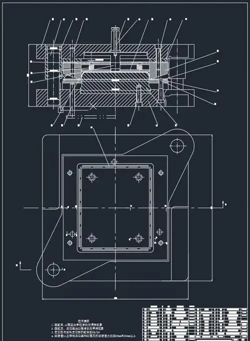
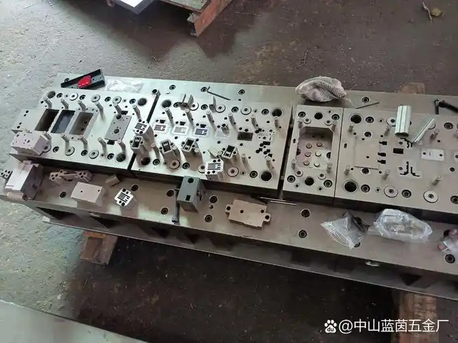
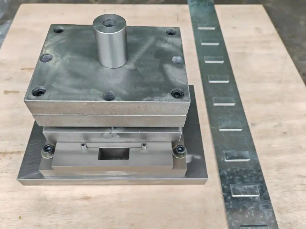
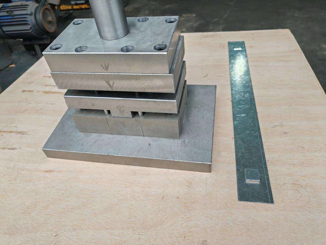
Pagrindiniai komponentai kiekviename štampavimo šablone
Ar kada nors domėjotės, kas iš tikrųjų yra tų milžiniškų metalinių štampavimo kaladėlių viduje, kurios gamina jūsų automobilio priekinę borto dalį ar šaldytuvo durų plokštę? Supratimas apie štampavimo kaladėlių vidinę architektūrą atskleidžia, kodėl komponentų parinkimas tikrai lemia detalės kokybę. Kiekvienas elementas atlieka tam tikrą funkciją, o kai jie beveik be trukdžių veikia kartu, kiekvieną kartą gaunamos tikslūs komponentai.
Dėžutės ir matricos bloko santykis
Įsivaizduokite sausainių formelę, kuri įspaudžiama per tešlą – tai esminis dėžutės ir matricos bloko santykis, tik sukonstruotas metalui ir veikiant didžiulėmis jėgomis. Dėžutė yra vyriškoji dalis, kuri aktyviai įeina į matricos bloką – moteriškąją dalį, turinčią tiksliai apdirbtą ertmę. Kai presas užsidaro, tarp šių dviejų elementų esantis metalas supjaunamas arba suformuojamas pagal tiksliausias specifikacijas.
Šis santykis reikalauja nepaprastos tikslumo. Pagal Gaminantis įmonė šių detalių pjovimo ir formavimo skyriai dažniausiai gaminami iš specialios kietinamosios plieninės medžiagos, vadinamos įrankių plienu, o kai kuriose aplikacijose reikia karbido ar kitų dėvėtis atsparių medžiagų. Tarp durklo ir matricos plyšio dydis – dažnai matuojamas tūkstantosiomis colio dalimis – tiesiogiai veikia kraštų kokybę, šukų susidarymą ir visos matricos tarnavimo trukmę.
Vadovo sistemos ir lygiavimo komponentai
Kas užtikrina viską tiksliai išlygiuotą per tuos galingus štampavimo ciklus? Vadovo žarnos ir įvorės čia yra nepastebimi herojai. Šie tiksliai apdirbti komponentai sužadinia matricos viršutinę ir apatinę plokštes su tikslumu, dažnai siekiančiu 0,0001 colio. Be tinkamo lygiavimo pastebėsite ankstyvą dėvėjimąsi, netikslų detalių gamybą ir galbūt katastrofišką matricos sugadinimą.
Dvi pagrindinės vedamosios ašties rūšys dominuoja pramonėje. Trinties aštys – tai tiksliai apdirbti, kietinti įrankių plieno vamzdeliai, poruojami su aliuminio-bronzo įvorėmis – kartais su grafito kištukais, kad būtų sumažinta trintis. Rutulinio guolio tipo vedamosios aštys užtikrina mažesnę trintį greitesnėms operacijoms ir lengvesnį šablonų plokščių atskyrimą techninės priežiūros metu. Abi sistemos turi tą pačią paskirtį: užtikrinti, kad smigiklis kiekvieno ciklo metu pataikytų į diegimo bloką tiksliai tame pačiame taške.
Papildomą stabilumą suteikia papildomieji atraminiai blokai. tiksliai apdirbti plieno blokai sugeria šoninę jėgą, kurią sukuria šablonų pjovimo ir formavimo operacijų metu. Jie ypač svarbūs, kai jėga veikia tam tikra kryptimi – be jų vedamosios aštys gali išsilenkti, dėl ko susidarys kritinių detalių nesutapimas.
Išstumtuvai ir medžiagų tvarkymo elementai
Štai ką daugelis žmonių praleidžia: kai metalas supjaunamas, jis natūraliai susitraukia aplink smigalų kūną. Be atskyrimo plokščių metalas kiltų kartu su smigalais, užstrigdavo štampavimo įrankyje ir sustabdydavo gamybą. Atskyrimo padai – spyruoklinėmis spyruoklėmis varomi plokščių elementai, apsupantys pjovimo smigalus – laiko metalą pritvirtintą prie apatinės štampo dalies, kai smigalai traukiami atgal.
Tačiau atskyrimo plokštės daro daugiau nei tik pašalina medžiagą. Jos taip pat laiko metalą plokščią arba pageidaujamos formos metu pjovimo operacijų, taip prisidedamos prie nuoseklaus gaminio kokybės. Daugelyje štampavimo įrankių įmontuotos padų langų angos – nuimamos plieninės detalės, kurios leidžia technikams atlikti priežiūrą ir keisti smigalus be viso atskyrimo plokščių komplekto nuėmimo.
Atpirkimo plokštės (taip pat vadinamos šablonų padėklais) paskirsto jėgą per visą šablono konstrukciją ir tarnauja kaip visų veikiančių komponentų montavimo pagrindas. Šios plieninės ar aliumininės plokštės turi būti apdirbtos lygiagrečiai ir plokščiai su kritinėmis nuokrypių ribomis. Padėklo storis priklauso nuo numatomų jėgų: metalą suspaudžiantis šablonas reikalauja žymiai storesnių padėklų nei paprastas pjovimo šablonas.
| Komponentas | Funkcija | Tipinės medžiagos | Dažniausi gedimų taškai |
|---|---|---|---|
| Šauksliukas | Vyrinis komponentas, įeinantis į šablonų bloką, kad supjaustumtų ar suformuotų metalą | Įrankių plienas (D2, A2, M2), karbido įdėklai | Briaunos skilimas, nusidėvėjimas, lūžimas dėl netinkamo išdėstymo |
| Formos blokas | Moterinis komponentas su ertme, į kurią įeina smigis | Įrankių plienas, karbidai aukšto nusidėvėjimo taikymams | Ertmės nusidėvėjimas, briaunų prastėjimas, įtrūkimai |
| Išstūmimo plokštė | Pašalina medžiagą nuo smigio po pjovimo ciklo | Žemo anglies turinio arba kietintas įrankių plienas | Spyruoklių nuovargis, nusidėvėjimas dėl metalo sąlyčio |
| Vadovaujančios kolonėlės | Tiksliai sujungia viršutinę ir apatinę štampavimo plokštės | Kietinta įrankių plieno medžiaga su vario-cinko padėklais | Lenkimas dėl netinkamo tvarkymo, dilimas |
| Pagrindinės plokštės | Paskirsto jėgą ir pritvirtina darbo komponentus | Plienas, aliuminio lydiniai | Išsivyniojimas dėl per didelės jėgos, nuovargio sukeltos įtrūkimai |
| Papilvės blokai | Sugeria šoninę stumties jėgą pjovimo ir formavimo metu | Plienas su aliuminio-vario-cinko dilimo plokštėmis | Užsikimšimas dėl to paties metalo sąlyčio, dilimas |
Supratimas, kaip šie metaliniai štampo komponentai veikia kiekviename štampavimo cikle, atskleidžia, kodėl kokybė svarbi kiekviename lygyje. Kalta nusileidžia žemyn, orientaciniai segtukai išlaiko tikslų išdėstymą, pjovimo štampas perpjauna medžiagą, išstumtuvai viską laiko vietoje, o atraminės plokštės sugeria jėgas – visa tai vyksta per dešimtųjų sekundės dalį ir gali kartotis milijonus kartų per štampo tarnavimo laiką. Renkantis komponentus kitam štampavimo taikymui prisiminkite, kad kiekvieno elemento kokybė tiesiogiai veikia galutinio gaminio kokybę ir gamybos efektyvumą.
Paaiškinta: progresyvieji, perduodamieji ir sudėtiniai štampai
Dabar, kai jau suprantate, kas yra štampavimo šablonuose, kyla kitas logiškas klausimas: kurio tipo šabloną iš tikrųjų turėtumėte naudoti? Pasirinkdami tarp progresyviųjų, perduodamųjų ir sudėtinių šablonų, ne tik priimate techninį sprendimą – tai tiesiogiai veikia jūsų gamybos kaštus, gaminio kokybę ir gamybos efektyvumą. Kiekvieno tipo šablonas puikiai tinka tam tikroms situacijoms, o šių skirtumų supratimas padeda priimti protingesnius įrankių investicijų sprendimus.
Progresyvinės iškirptuvės didelėms serijoms
Įsivaizduokite, kad metalinė juosta nuolat tiekiama per kelis stoties vienetus, kai kiekvienas vienetas atlieka tam tikrą operaciją – pjovimą, lenkimą, formavimą arba skverbimąsi. Tai ir yra progresyviųjų šablonų esmė, todėl jie vyrauja didelės apimties gamyboje .
Paeiliškieji štampai susideda iš kelių stotyčių, išdėstytų vienoje štampoje seka. Kai metalinė juosta juda per presą, kiekviena stotis atlieka jam priskirtą operaciją, kol galutinis gaminys išeina paskutinėje stotyje. Pagal Larson Tool ši sistema leidžia gaminti sudėtingus detalių naudojant paprastus žingsnius ir pasiekti nepaprastą visų pagamintų komponentų vienodumą.
Kas daro paeiliškuosius štampus tokiais patraukliais pramonės įmonėse naudojamoms štampo pjovimo mašinoms? Greitis ir nuoseklumas. Kai juosta pradeda judėti, detalės nuolat išeina iš linijos – nereikia rankinio tvarkymo tarp operacijų, nekyla klaidų dėl perkėlimo į kitą padėtį. Automobilių pramonė labai dažnai naudoja paeiliškuosius štampus gamindama laikiklius, spaustukus ir sudėtingas dalis, kurios gaminamos dideliais kiekiais, todėl pateisinamas didesnis pradinis įrankių gamybos investicijos dydis.
Tačiau progresyviosios šabloninės formos reikalauja kruopštaus projektavimo ir tikslaus inžinerinio sprendimo. Pradinės sąnaudos yra didesnės nei paprastesnių šablonų, tačiau čia yra kompromisas: vieno gaminio sąnaudos žymiai sumažėja didelėse gamybos serijose. Jei gaminama tūkstančiai ar milijonai identiškų detalių, progresyviosios šabloninės formos užtikrina nepasiekiama efektyvumą.
Perkėlimo štampai sudėtingoms didelėms detalėms
Ką daryti, kai jūsų detalės per didelės ar per sudėtingos nuolatiniam juostos tiekimui? Štai kur išsiskiria perkėlimo šabloninės formos. Skirtingai nuo progresyviųjų šablonų, kurios visą apdorojimo procesą laiko darbo gabalą prijungtą prie juostos, perkėlimo šabloninės formos naudoja mechaninius perkėlimo sistemas, kad perduotų atskirus tuščius gabalus tarp atskirų stotyčių.
Šis požiūris siūlo unikalių privalumų reikalaučioms aplikacijoms. „Durex Inc.“ pastebi, kad perduodamieji štampavimo įrankiai ypač tinka didelėms gamybos apimtims ir sudėtingoms surinktuvėms, užtikrindami mastelio keitimą ir tikslumą, kurio negali pasiekti kitos metodikos. Kontroliuojami perdavimo procesai išlaiko aukštą tikslumą, užtikrindami, kad kiekvienas komponentas atitiktų griežtus kokybės standartus – tai ypač svarbu aviacijos ir sunkiosios technikos taikymuose.
Įsivaizduokite perduodamuosius štampavimo įrankius kaip daugiafunkcinius peilius štampavime. Jie tvarko didesnius detalių gabalus, kurie tiesiog nepatelpa į progresyvių štampavimo įrankių stotis. Jie leidžia apdoroti sudėtingas geometrijas, reikalaujančias operacijų iš kelių kampų. Be to, jie leidžia štampavimo įrankiams atlikti gilų traukimą, išplėstinį formavimą ir sudėtingą formavimą, kuris būtų neįmanomas naudojant juostomis maitinamas sistemas.
Kompromisas? Perduodamieji štampai reikalauja didesnių įrankių ir paruošimo sąnaudų dėl sudėtingų perduodamųjų mechanizmų. Mechaninės sistemos, kurios judina dalis tarp stotyčių, reikalauja reguliarios priežiūros, kad būtų išvengta netikslumų ar detalių defektų. Tačiau vidutinėms ir aukštoms gamybos serijoms, kai svarbūs universalumas ir galimybės, šis investicinis įsipareigojimas atsiperka.
Sudėtinės štampavimo formos tiksliesiems vienkartinio stūmimo veiksmams
Kartais paprastumas laimi. Sudėtiniai štampai atlieka kelias operacijas – dažniausiai pjovimą ir išpjovimą – vienu preso įspaudimu. Tuo tarpu progresyvieji štampai operacijas paskirsto į kelias stotytes, o sudėtiniai štampai jas sujungia į vieną galingą judėjimą.
Šis pjovimo ir štampavimo metodas puikiai tinka plokščioms, paprastoms detalėms, kai svarbūs tikslūs matmenys. Simultaniškas veiksmas užtikrina tobulą operacijų lygiavimą, pašalindamas kaupiamuosius pozicionavimo klaidų rizikos veiksnius, kurie gali kilti per kelias stotytes. Kai reikia tikslaus štampavimo su minimaliu nuokrypiu, sudėtiniai štampai tai užtikrina.
Pag according to pramonės šaltiniams, sudėtiniai šablonai paprastai yra pigesni projektuoti ir gaminti lyginant su progresyviais šablonais. Jų paprastesnė konstrukcija sumažina pradines sąnaudas ir reikalauja mažiau priežiūros. Tačiau jie mažiau tinka sudėtingiems ar didelės apimties projektams, kur progresyvieji šablonai ilgainiui būtų ekonomiškesni.
Medicinos prietaisų komponentai ir vartojimo prekės dažnai naudingai naudoja sudėtinių šablonų gamybą. Šios programinės įrangos paprastai reikalauja vidutinės gamybos apimties sudėtingų, bet santykinai plokščių komponentų – tai puikiai tinka vieno smūgio tikslumui, kurį suteikia sudėtiniai šablonai.
| Kriterijai | Progresyvios mirtys | Pervadiniai šablonai | Sudėtinės formos |
|---|---|---|---|
| Gaminių kiekio tinkamumas | Didelis tūris (tūkstančiai–milijonai) | Vidutinė–aukšta apimtis | Žema–vidutinė apimtis |
| Detalių sudėtingumo galimybės | Sudėtingi detalės per sekvencines operacijas | Ypač sudėtingos, didelės surinktos konstrukcijos | Paprastos iki vidutiniškai sudėtingos plokščios detalės |
| Tipinės pramonės šakos | Automobilių pramonė, elektronika, buitinė technika | Aviacija, sunkioji technika, didelė automobilių pramonė | Medicinos prietaisai, vartojimo prekės, elektronika |
| Privalumai | Didelis greitis, nuolatinė kokybė, žema kaina už vieną detalę masinėje gamyboje | Gali apdoroti didelius komponentus, universalios operacijos, mastoma | Žemesnės šablonų sąnaudos, tikslūs leidžiamieji nuokrypiai, paprastesnė priežiūra |
| Ribotumai | Didesnės pradinės sąnaudos, reikalauja reguliarios priežiūros | Didesnės įrengimo sąnaudos, sudėtinga perkėlimo mechanizmo priežiūra | Tinka tik paprastesniems detalių tipams, lėtesnis didelėms gamybos apimtims |
Pasirinkdami tarp šių trijų šablonų tipų galutinai turime pritaikyti savo gamybos reikalavimus kiekvienos sistemos stiprybėms. Didelėms automobilių detalių gamybos apimtims – progresyvūs šablonai yra racionalus sprendimas. Dideliems lėktuvų konstrukcijų surinkimams, reikalaujantiems sudėtingo formavimo – jūsų atsakymas yra perkėlimo šablonai. Tikslūs plokščios formos komponentai vidutinėmis gamybos apimtimis – sudėtiniai šablonai užtikrina puikią vertę. Šių skirtumų supratimas – o ne įprastų variantų pasirinkimas be išsamios analizės – užtikrina, kad jūsų įrankių investicija tikrai tarnautų jūsų gamybos tikslams.
Medžiagos ir paviršiaus apdorojimai optimaliam našumui užtikrinti
Jūs jau pasirinkote štampavimo šablonų tipą ir suprantate, kaip komponentai veikia kartu – tačiau čia daugelis gamintojų susiduria su sunkumais. Štampavimo šablonuose naudojamos medžiagos nulemia, ar jūs pasieksite milijonus kokybiškų ciklų, ar patirsite ankstyvą gedimą jau po tūkstančių ciklų. Teisingo įrankių plieno, jo kietumo laipsnio ir paviršiaus apdorojimo pasirinkimas – tai ne tik techninės smulkmenos; tai skirtumas tarp pelningos gamybos ir brangios prastovos.
Įrankių plieno pasirinkimas pagal panaudojimą
Ne visi įrankių plienai yra vienodai tinkami. Kiekvienas plieno žymos tipas turi specifines savybes, kurios ypač tinka tam tikroms gamybos problemoms. Nustatant medžiagas spaustuvų pjovimo šablonams, šių skirtumų supratimas yra būtinas, kad būtų priimtos informuotos sprendimų.
D2 įrankių plienas yra naudojamas kaip darbo žirgas šaltųjų apdorojimų taikymuose. Pagal „Nifty Alloys“ duomenis, D2 plieno savybės užtikrina nuostabią nusidėvėjimo atsparumą, todėl jis yra idealus aukšto tūrio išpjovų ir štampavimo operacijoms. Didelis chromo kiekis sukuria chromo karbidus visame plieno matricoje, užtikrindamas nepaprastą atsparumą abrazyviniam nusidėvėjimui. Tačiau šis paties kietumas daro D2 sunkesnį apdirbti nei minkštesnius plieno rūšių – tai kompromisas, kurį reikėtų įvertinti kalibruojant šablonus.
A2 Įrankių plienas siūlo subalansuotą požiūrį. Jis užtikrina gerą nusidėvėjimo atsparumą, tuo pat metu išlaikydamas geresnę kietumą nei D2. Dėl to A2 tinka bendrojo paskirties metalo pjovimo šablonams, kai reikia ilgaamžiškumo be ekstremalaus trapumo. Daugelis gamintojų pasirenka A2 dirbdami su vidutinio storio medžiagomis vidutiniais gamybos tūriais.
S7 įrankių plienas pirmiausia vertina smūgio atsparumą. Kai jūsų štampavimo įrankių taikymas apima smūginį apkrovimą – pavyzdžiui, kalnakalio štampus arba kirtiklius, kurie yra veikiami kartotinių didelės jėgos smūgių, – S7 lyginamasis stiprumas neleidžia katastrofiškų įtrūkimų, kuriuos gali patirti kietesni plienai. Jis sugeria energiją vietoje to, kad perduotų ją per konstrukciją.
M2 aukštos kokybės plienas įtraukiamas į diskusiją, kai svarbus pjovimo greitis. Šis plieno tipas išlaiko savo kietumą net aukštesnėse temperatūrose, kurios susidaro vykdant greitąjį pjovimą. Greitaeigėse ciklinėse metalo pjovimo štampo operacijose M2 užtikrina nuolatinę našumą ten, kur kiti plieno tipai suminkštėtų ir pasiduotų.
Kietumo ir nusidėvėjimo atsparumo reikalavimai
Skamba sudėtingai? Štai pagrindinis principas: kietumas ir stiprumas yra priešingos sąvokos. Padidinus vieną, paprastai prarandamas kitas. Jūsų gamybos reikalavimai nusako, kur reikia pasiekti šį pusiausvyrą.
Didelės apimties gamybai, kai išspaudžiamos milijoninės detalių partijos, reikia maksimalios nusidėvėjimo atsparumo – tai reiškia didesnį kietumą 58–62 HRC diapazone. Šie medžiagų pjovimo šablonai išlaikys savo pjovimo kraštus ir matmeninę tikslumą ilgą laiką trunkančiose gamybos serijose. Tačiau prisiminkite: ekstremalus kietumas reiškia padidėjusią trapumą. Jei jūsų šablonas patiria smūginį apkrovimą arba presas nėra visiškai sucentruotas, tie ypatingai kieti komponentai gali įtrūkti vietoj to, kad deformuotųsi.
Vidutinės apimties taikymo srityse dažnai naudinga vidutinio kietumo (apie 54–58 HRC) medžiaga. Šis kietumo diapazonas užtikrina pakankamą nusidėvėjimo atsparumą šimtams tūkstančių ciklų, tuo pačiu išlaikant pakankamai stiprumo, kad būtų galima išlaikyti atsitiktinius padavimo sutrikimus arba centruojamojo įrenginio nuokrypius be katastrofiško verslo nutraukimo.
Medžiaga, kurią štampuojate, taip pat yra svarbi. Štampuojant abrazyvias medžiagas, pvz., nerūdijančiąją plieną ar stipriuosius mažalegiriuotus plienus, reikia kietesnių štampo detalių nei štampuojant minkštą aliuminį ar vario lydinius. Storesnės medžiagos reikalauja didesnės jėgos, kuri sukuria daugiau šilumos ir dėvėjimosi – todėl reikalavimai linksta į kietesnius ir atspariau dėvėjimuisi žymiai geriau pritaikytus lydinius.
Medžiagų pasirinkimas – tai ne tik pradinės sąnaudos, bet ir viso naudojimo ciklo sąnaudos. Aukštos kokybės įrankių plienas, kuris pradžioje kainuoja 30 % brangiau, bet tarnauja 300 % ilgiau, yra žymiai geresnis investicinis sprendimas nei pigesnės alternatyvos, kurios reikalauja dažno keitimo ir gamybos pertraukų.
Paviršiaus apdorojimai, padedantys pratęsti matricų tarnavimo laiką
Net geriausias įrankių plienas naudingai veikia tik su paviršiaus pagerinimu. Šiuolaikiniai paviršiaus apdorojimai sukuria apsauginius sluoksnius, kurie žymiai padidina štampo tarnavimo trukmę, sumažina trintį ir pagerina gaminamų detalių kokybę.
Nitridavimas sklaido azotą į plieno paviršių, sukuriant itin kietą paviršiaus sluoksnį be keičiamų šerdies savybių. Šis apdorojimas ypač gerai tinka šablonams, kuriems reikalinga tiek paviršiaus kietumas, tiek šerdies stiprumas. Procesas vyksta santykinai žemose temperatūrose, todėl mažinamas tiksliai apdirbtų detalių išsivyniojimas.
Chrominis apdailas jau dešimtmečius tarnauja pramonei, užtikrindama kietą, korozijai atsparią paviršiaus dangą. Tačiau tradiciniam chromavimui būdingi tam tikri apribojimai. Pagal Northeast Coating , PVD būdu nusodintos dangos užtikrina kietesnį paviršių nei įprastinis kietasis chromavimas, o taip pat nusodina ploną, vienodą sluoksnį, kuris kraštų neaptraukia kaip tradicinės drėgnos elektrochromavimo dangos.
PVD (fizinė garų nusodinimo) dangos atspindi šiuolaikinį aukštos našumo štampų standartą. Šios vakuumo nuosėdų dengiamosios medžiagos – įskaitant titano nitridą (TiN), chromo nitridą (CrN) ir titano-aliuminio nitridą (AlTiN) – suteikia daugybę privalumų. Jos padidina paviršiaus kietumą iki 80+ HRC ekvivalento, sumažina trinties koeficientus, neleidžia medžiagai sukibti su štampo paviršiumi ir atsparios korozijai, kurią sukelia reaktyvios medžiagos. Svarbu paminėti, kad PVD dengiamosios medžiagos gali būti nusodintos žemose temperatūrose, todėl nepakeičiamos plieno šerdies savybės.
Karbūro įterpiai tampa būtini tuomet, kai net dengta įrankių plieno medžiaga negali atitikti ilgaamžiškumo reikalavimų. Volframo karbido įdėklai pasižymi kietumu, artėjančiu prie 90 HRC, ir dėvėjimosi atsparumu, kuris žymiai viršija bet kurio įrankių plieno rodiklius. Jie yra būtini metalinių šablonų pjovimui, kai naudojamos itin abrazyvinės medžiagos, ultraaukštos gamybos apimtys, viršijančios milijoną ciklų, arba kai reikalinga išskirtinė matmenų stabilumas ilgalaikiams darbams. Kokia kaina? Karbidas yra žymiai brangesnis ir trapesnis už įrankių plieną – tačiau tinkamose aplikacijose jis vienintelis užtikrina palyginamą našumą.
Pasirinkdami medžiagas savo kalibruojamiesiems šablonams, įvertinkite šiuos svarbius veiksnius:
- Numatomas gamybos apimtis – Aukštesnės gamybos apimtys reikalauja kietesnių, dėvėjimosi atsparesnių medžiagų bei paviršiaus apdorojimų
- Lakštų metalo tipas ir storis – Abrazyvinės ir storesnės medžiagos reikalauja aukštos kokybės įrankių plienų arba karbido įdėklų
- Reikalaujami tikslumai – Tikslūs matmenys reikalauja medžiagų, kurios išlaiko matmenų stabilumą
- Biudžeto apribojimai – Išsverti pradinę investiciją prieš visos naudojimo trukmės sąnaudas, įskaitant techninę priežiūrą ir pakeitimus
Medžiagų pasirinkimas yra vienas svarbiausių sprendimų štampavimo šablonų projektavime – tačiau jis nepasirenkamas izoliuotai. Tai, kaip medžiagos suformuojamos ir kokie tolerancijų reikalavimai taikomi šablonų gamybos metu, lemia, ar jūsų investicija duos tikėtiną našumą.
Šablonų projektavimo principai, kurie nulemia gaminio kokybę
Jūs pasirinkote aukščiausios kokybės medžiagas savo štampavimo šablonui – tačiau čia yra realybės patikrinimas. Net geriausias įrankių plienas negali išgelbėti netinkamai suprojektuotos įrangos. Šablonų projektavimo principai, ypač tarpų apskaičiavimai ir tolerancijų nustatymo sprendimai, tiesiogiai lemia, ar jūsų detalės atitinka technines specifikacijas arba baigia šiukšliadėžėje. Šių pagrindų supratimas paverčia gerus šablonus puikiuose.
Tinkamo šablono tarpo apskaičiavimas
Kas iš tikrųjų yra štampo tarpelis? Tai tarpas tarp kirpimo krašto (kaltuvo) ir atitinkamo štampo bloko krašto. Pagal MISUMI, šis tarpelis tiksliai apskaičiuojamas remiantis medžiagos storiu, rūšimi ir pageidaujama gaminio kokybe. Tinkamas tarpelis užtikrina efektyvų pjovimą kalant, sumažina įrankių nusidėvėjimą ir mažina defektų, tokių kaip kraštų iškilimai (burrai), deformacija arba pernelyg ankstyvas įrankių sugadinimas, riziką.
Galvokite taip: per mažas tarpelis priverčia kaltuvą ir štampą dirbti sunkiau nei reikia, sukelia per didelį šilumos kiekį ir greitina nusidėvėjimą. Per didelis tarpelis leidžia medžiagai lenktis ir plyšti vietoj to, kad būtų švariai supjaustyta, todėl susidaro nešvarūs kraštai ir per dideli kraštų iškilimai (burrai). Idealių sąlygų pasiekti reikia suprasti, kaip skirtingos medžiagos elgiasi veikiamos pjovimo jėgos.
Daugumai taikymų tarpas nurodomas kaip procentinė medžiagos storio dalis kiekvienoje pusėje. Minkštesnėms medžiagoms, pvz., aliuminiui, paprastai reikia 5–8 % tarpo kiekvienoje pusėje, o kietesnėms medžiagoms, pvz., nerūdijančiajam plienui, – 8–12 %. Didelės stiprumo mažoleginiai plienai gali dar labiau padidinti šiuos reikalavimus – kartais pasiekiant net 15 % ypatingai kietoms rūšims.
Štai kas nutinka, kai tarpas nustatomas neteisingai: nepakankamas tarpas verčia smigiklį traukti per medžiagą, dėl ko pjovimo kraštai labiau susidėvi ir presui tenka išvystyti didesnę jėgą. Per didelis tarpas sukuria apsukimo zoną, po kurios seką grublėtos lūžio paviršiai vietoj švaraus pjovimo plokštumų. Abiem atvejais sumažėja gaminio kokybė ir trumpėja štampų tarnavimo laikas – būtent to išvengia tinkamas projektavimas.
Medžiagos storis ir konstrukcijos koreguojami elementai
Medžiagos storis esminiu būdu keičia tai, kaip turi būti suprojektuotas jūsų štampas. Kaip minėta Five Flute projektavimo vadovą , suprantant, kaip lakštų medžiagos reaguoja į formavimo įtempimus, kuriama veiksmingos konstrukcijos pagrindas. Santykis tarp storio ir konstrukcinės sprendimo priėmimo išplėstas daug toliau nei paprasti tarpų skaičiavimai.
Apsvarstykite skylės vietą santykinai kraštų. Pramonės rekomendacijos rekomenduoja skyles išdėstyti maždaug 1,5 karto medžiagos storio atstumu nuo kraštų ir 2 kartus medžiagos storio atstumu vieną nuo kitos. Kodėl? Per arti viena kitos ar per arti kraštų išdėstyti elementai sukelia medžiagos iškraipymą štampavimo ciklo metu. Išpjovimo štampo efektyvumas sumažėja, nes medžiaga negali tinkamai tekėti pjovimo veiksmo metu.
Lenkimai įveda papildomos sudėtingumo. Skyles ir elementus reikia išdėstyti ne arčiau kaip 2,5 karto storis plius vienas lenkimo spindulys nuo lenkimo linijų. Šio nurodymo nepaisymas gali sukelti iškreiptus elementus, nes medžiaga išsitempia ir suspaudžiama formavimo metu. Diezpijimo mašinos popierius gali atleisti tokius netikslumus, tačiau pramoniniai štampavimo šablonai, veikiantys milžiniška jėga, to neleis.
Medžiagos storis taip pat veikia minimalius elementų dydžius. Venkite skylų su skersmenimis mažesniais nei medžiagos storis – jų švariai išpjauti nepavyks. Įpjovos ir išpjovos taip pat turi būti suprojektuotos pagal panašią logiką: minimalūs plotis turėtų būti lygūs arba didesni nei medžiagos storis, o ilgis turėtų būti bent dvigubai didesnis už plotį, kad būtų užtikrintas tinkamas pjovimo veiksmas.
Tolerancijos nuoseklaus detalės kokybės užtikrinimui
Tolerancijos nusako leistiną nuokrypį jūsų gatavuose detalių elementuose – ir jos veikia visą štampavimo įrankių projektavimo procesą. Švelnesnės tolerancijos reikalauja tikslesnių pritaikymų tarp kaladės ir štampo komponentų, dėl ko normalios eksploatacijos metu susidaro didesnis ausis. Iššūkis yra nustatyti tolerancijas pakankamai tiksliai, kad būtų užtikrintos funkcionaliosios reikalavimų sąlygos, bet nepadarant nereikalingų papildomų išlaidų.
Pagal lakštinių metalų gamybos dizaino (DFM) principus, tolerancijos turėtų būti kuo didesnės, kur tik įmanoma, kad būtų sumažintos gamybos išlaidos. Tai nereiškia prastos kokybės priėmimo – tai reiškia supratimą, kurie matmenys iš tikrųjų yra svarbūs funkcionaliai, o kurie gali turėti platesnį leistiną nuokrypį, neįtakodami detalės veikimo.
- Analizuoti medžiagos savybes – Prieš projektuojant bet kokius štampo elementus, dokumentuoti konkrečią lydinio rūšį, kietumą, storio toleranciją ir grūdų krypties reikalavimus
- Nustatyti funkcionaliuosius reikalavimus – Nustatyti, kurie matmenys yra kritiniai detalės veikimui, o kurie tiesiog turi būti „pakankamai tikslūs“
- Apskaičiuoti optimalius tarpus – Nustatykite tinkamus išpjovimo operacijoms laisvumų procentus, remdamiesi medžiagos rūšimi ir storiu
- Nustatykite elementų tarpusavio atstumus – Taikykite minimalius atstumo reikalavimus, grindžiamus medžiagos storiu, skylėms, įpjovoms, lenkimams ir kraštams
- Nurodykite leistinų nuokrypių zonas – Tiksliausius leistinus nuokrypius priskirkite tik ten, kur jie funkcionaliai būtini; kitur naudokite standartinius leistinus nuokrypius
- Atsižvelkite į kumuliacinį pokytį – Keliais lenkimais išdėstyti elementai kaupia padėties paklaidas; atitinkamai suplanuokite leistinų nuokrypių biudžetą
- Dokumentuokite reikalavimus dėl plaušo krypties – Nurodykite, kada lenkimo linijos turi būti statmenos plaušo krypčiai, kad būtų išvengta įtrūkimų
- Suplanuokite dėl dangos storio – Jei detalės padengiamos miltelinėmis dėžėmis, anodinėmis arba metalinėmis dangomis, atsižvelkite į matmenines paklaidas savo tolerancijų stulpe
Tolerancijų aptarimuose ypač svarbu kreipti dėmesį į kraštų kokybę. Pjovimo procesas sukuria skirtingas zonas pjautinio krašto srityje: apvyniojimo zoną, kur medžiaga lenkiamasi į pjūvį, pjovimo zoną su lygiomis, blizgančiomis paviršiaus sritimis, lūžio zoną su grubesne struktūra ir šukų zoną išėjimo pusėje. Optimalus tarpas maksimaliai padidina pjovimo zoną, tuo pat metu sumažindamas apvyniojimą ir šukas. Nustatant kraštų kokybės tolerancijas, nurodykite, kurie paviršiai yra kritiniai, o kurie gali atitikti standartines pjovimo charakteristikas.
Matmenų tikslumas labai priklauso nuo nuoseklių štampavimo šablonų (progresyvių šablonų) juostos vietai. Pilotiniai smeigtais tiksliai nustato kiekvienos juostos padėtį, tačiau jų veiksmingumas priklauso nuo tinkamai suprojektuotų pilotinių skylės ir atitinkamų tarpų. Net nedidelės juostos padėties nuokrypiai tiesiogiai lemia matmenines klaidas galutinėse detalėse – ypač tada, kai šios savybės yra toli nuo pilotinių skylės vietos.
Paviršiaus apdorojimo reikalavimai taip pat įtakoja projektavimo sprendimus. Štampavimas savo prigimtimi sukuria skirtingas paviršiaus savybes kalapno (punch) ir šablonų (die) pusėse. Jei jūsų taikymui reikalinga tam tikra paviršiaus kokybė, šablonas turi būti suprojektuotas atitinkamai – galbūt reikės papildomų operacijų arba griežtesnių komponentų tolerancijų, kad būtų pasiektas pageidaujamas rezultatas.
Šie projektavimo principai neegzistuoja izoliuoti. Kiekvienas tarpų skaičiavimas, medžiagos įvertinimas ir tolerancijų nustatymas turi atsižvelgti į tai, kaip jūsų šablonas integruojasi su spaustuvės įranga, kuri jį varo.
Štampavimo šablonų integruojimas su presais
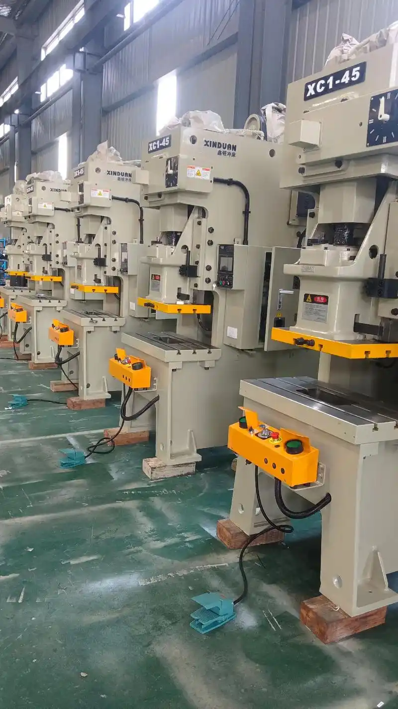
Jūs sukūrėte idealų šabloną su optimaliais tarpais ir aukščiausios kokybės medžiagomis – bet čia svarbiausias klausimas: ar jis iš tikrųjų veiks jūsų presuose? Šablonų ir presų integracija yra vienas dažniausiai nepastebimų štampavimo sėkmės aspektų. Jei tai padarysite neteisingai, net tobulybės šablonai veiks neefektyviai, per anksti susidėvės arba žlugs katastrofiškai. Tonų reikalavimų, ėjimo ilgio koordinavimo ir tiekimo sistemų supratimas paverčia teorinį šablonų projektavimą praktine gamybos realybe.
Šablonų reikalavimų pritaikymas prie presų tonų
Kiek jėgos iš tikrųjų reikia jūsų štampavimo operacijai? Pagal Gaminantis įmonė skaičiuojant preso tonazą reikia įvertinti daug daugiau nei tik pagrindinę pjovimo ar formavimo operaciją. Reikia išnagrinėti visą darbą, kurį atlieka presas kiekviename šablonų stotyje – įskaitant skeleto laužą, detalių juostos nešėją, pilotinių skylių probadymą, spyruoklinių nuimtuvų slėgį, juostos pakėlimo smeigtukų slėgį, azoto slėgio padus, varomuosius krumpliaratukus ir galutinį juostos laužo pjovimą.
Pagalvokite taip: kiekviena operacija, vykstanti tuo pačiu preso ėjimu, prideda prie jūsų tonazės poreikio. Skylių probadymas, traukimas, formavimas, lenkimas, monetavimas ir šablonavimas – visos šios stotys prisideda prie bendros apkrovos. Kai įrašysite apkrovą kiekvienoje stotyje, sudėkite jas, kad gautumėte bendrą presui reikalingą tonazą.
Tačiau vien tik tonų kiekis nepateikia visos situacijos. Taip pat svarbūs energijos skaičiavimai – nes galite turėti pakankamą tonų kiekį, bet nepakankamai energijos. Toks neatitikimas yra dažna priežastis, dėl kurios presai užsikimšta žemiausiojo miračiojo taško (BDC) metu. Kai presas neturi pakankamai energijos, kad baigtų judėjimo ciklą, gamyba sustoja labiausiai erzinančiu būdu.
Šiuos skaičiavimus pagrindžia medžiagos savybės. Jums būtina žinoti ritės medžiagos pjovimo stiprį ir tempimo stiprį svarais kvadratinėje colyje, taip pat medžiagos storį coliuose. Aukšto greičio operacijoms, kuriose naudojamos aukšto stiprumo medžiagos ir atliekami ištempimo skaičiavimai, būtinas žinoti galutinį tempimo stiprį.
| Medžiagos storio diapazonas | Tipiški tonų reikalavimai | Rekomenduojamos presų rūšys |
|---|---|---|
| 0,010" – 0,030" (plonas lakštas) | 5 – 50 tonų | Tarpinės konstrukcijos presai, OBI presai |
| 0,031" – 0,060" (vidutinio storio lakštas) | 50 – 200 tonų | Stačiakampės konstrukcijos presai, progresyvių šablonų presai |
| 0,061" – 0,125" (storas lakštas) | 200–600 tonų | Tiesios kraštinės su stipriomis atraminėmis plokštėmis |
| 0,126–0,250 colio (plokštė) | 600–2000+ tonų | Didelės tiesios kraštinės hidrauliniai presai |
Štai kas dažnai praleidžiama daugelio inžinierių: preso tonų klasifikacija ir deformacijos specifikacijos grindžiamos prielaida, kad šablonų apkrova vienodai pasiskirsto ant dviejų trečdalių preso lentos ploto. Neteisingai įdėję šabloną, veikiate už šių projektavimo parametrų ribų – net jei apskaičiuota tonų vertė atitinka nustatytus reikalavimus.
Stroko ilgio ir padavimo sistemos sinchronizavimas
Stroko ilgis – tai atstumas, kurį įrankis (ram) nueina nuo viršutinės mirtingosios pozicijos iki apatinės mirtingosios pozicijos – tiesiogiai veikia tiek šablonų konstrukciją, tiek gamybos našumą. Per trumpas strokas riboja galimas operacijas. Per ilgas strokas vartoja energiją be reikalo ir nežymiai sulėtina ciklo trukmę.
Progresyviems štampavimo šablonams įžengimo ilgis turi ne tik atitikti formavimo operacijas, bet taip pat ir medžiagos padavimo sistemą. Pilotiniai smeigtaukščiai tiksliai nustato kiekvieno juostos judėjimą, užtikrindami nuolatinę padėtį ciklą po ciklo. Tačiau šios sistemos veikia tik tuomet, kai įžengimo ilgis, padavimo ilgis ir šablono sinchronizacija visiškai sutampa.
Automatiniai padavikliai – būtų tai rituliniai padavikliai, griebikliai arba servorinės sistemos – turi perduoti medžiagą tuo įžengimo laikotarpiu, kai kaladės yra visiškai išėjusios iš juostos. Šis laiko langas susiaurėja didėjant preso greičiui, todėl reikalaujama tikslaus derinimo tarp šablonų mašininėms operacijoms ir padavimo sistemos galimybių.
Skirtingai nuo dažymo pjūvių meno pritaikymuose, kur rankinis padavimas veikia puikiai, pramoninis štampavimas reikalauja automatizuotos tikslumo. Juostos pakėlimo smeigtaukščiai kiekvieno įžengimo metu šiek tiek pakelia medžiagą, leisdami švarų judėjimą be traukimo per šablonų paviršius. Šie, atrodo, nedideli komponentai žymiai paveikia tiek gaminio kokybę, tiek šablonų tarnavimo trukmę.
Štampavimo įrankių apsaugos ir stebėjimo sistemos
Kas nutinka, jei ciklo metu kažkas sugenda? Be tinkamų apsaugos sistemų, neteisingas maitinimas ar dvigubas smūgis gali per sekundės dalį sunaikinti štampavimo įrankius, kurių vertė siekia dešimtis tūkstančių dolerių. Šiuolaikinės štampavimo įrankių apsaugos sistemos neleidžia šioms katastrofiškoms avarijoms įvykti.
Uždarymo aukštis – atstumas tarp preso pagrindo ir stūmoklio žemiausiojo taško – turi tiksliai atitikti jūsų štampavimo įrankių reikalavimus. Per mažas uždarymo aukštis reiškia, kad štampavimo įrankis negali visiškai užsidaryti. Per didelis uždarymo aukštis sukuria per didelį tarpą, leidžiantį judėjimą veikimo metu. Reguliuojamos uždarymo aukščio mechanizmai leidžia tiksliai sureguliuoti šį parametrą, tačiau štampavimo įrankis turi būti suprojektuotas taip, kad tilptų į preso reguliavimo diapazoną.
Jutiminės sistemos prideda dar vieną apsaugos sluoksnį. Išmetimo jutikliai patvirtina, kad baigti detalės tinkamai išmestos prieš pradedant kitą ciklą. Netinkamo tiekimo aptikimo įrenginiai nustato, kai juostos medžiaga nepraeina tinkamai. Štampavimo šablonų apsaugos sistemos stebi jėgos kreives kiekviename įspaudimo cikle ir nedelsiant sustabdo presą, jei apkrovos viršija programuotus ribos rodiklius.
Šį požiūrį galima palyginti su tuo, kaip dažymo iškirpimo entuziastai saugo savo amatininkų įrangą – tik pramoninės pasekmės matuojamos sunaikinta įrankių sistema ir gamybos delsais, o ne sugadintu popieriumi. Investicija į tinkamas jutiminės sistemas atsipildo tik vieno didelio šablonų susidūrimo prevencijos metu.
Tinkama šablono ir preso integracija pati savaime dar ne garantuoja sėkmės. Teisingos šablono konfigūracijos pasirinkimas konkrečioms gamybos reikmėms lemia, ar ši integracija duos norimus rezultatus.
Teisingo štampavimo šablono pasirinkimas jūsų taikymui
Jūs suprantate štampų tipus, medžiagas ir presų integraciją – bet kaip iš tikrųjų pasirinkti tinkamiausią konfigūraciją savo konkretam projektui? Būtent čia daugelis gamintojų susiduria su sunkumais. Be aiškaus sprendimų priėmimo rėmo įrankių investicijos tampa apmąstytais spėjimais, o ne strateginiais pasirinkimais. Sukurkime praktišką parinkimo procesą, kuris atitiktų jūsų gamybos reikalavimus ir optimalias štampų konfigūracijas.
Štampų parinkimo strategija, pagrįsta gamybos apimtimis
Gamybos apimtis yra pagrindinis veiksnys, lemiantis štampų parinkimą. Pagal Zintilon štampų parinkimo vadovą, metinės gamybos apimties įvertinimas yra būtinas skirtingų štampų tipų investicijoms pateisinti. Tačiau apimčių vertinimas išeina už paprastų detalių kiekių ribų – taip pat reikia analizuoti numatomas partijų dydžius, gamybos dažnumą bei galimus apimčių pokyčius laikui bėgant.
Pagalvokite apie tai taip: jungtinė matrica, kainuojanti 15 000 dolerių, gali atrodyti brangi 5000 dalių. Tačiau tas pats investivimas tampa nepaprastai ekonomiškai efektyvus, jei kiekis netikėtai išaugs iki 50 000 per metus. Kita vertus, investuojant 80 000 dolerių į pažangias priemones gaminiui, kuris niekada neviršija prototipo kiekio, švaistomas kapitalas, kuris galėtų finansuoti kitus projektus.
Štai praktinė tvarka, kaip priimti sprendimus pagal apimtį:
- Prototypų kiekis (1-500 dalių) Pagalvokite apie minkštus įrankius, vienpakopį formą arba net lazerio pjaustymą. Tikslas - patvirtinti dizainą prieš pradedant gaminti įrankius.
- Mažas kiekis (500-10.000 dalių per metus) Paprastai geriausia vertė teikiama sudėtinių arba paprastų vienpakopinių formų formų formomis. Įrankių sąnaudos išlieka tvarkomos, tačiau vis dar užtikrinama pastovi kokybė.
- Vidutinis tūris (10.000-100.000 dalių per metus) Progresyviosios matmenys tampa ekonomiškai patrauklios, nes dalis kainuoja žymiai mažiau. Perdavimo matrai tinka didesnėms, sudėtingesnėms dalims tokiuose tūriuose.
- Didelė apimtis (daugiau nei 100 000 detalių per metus) – Paeiliškieji šablonai dominuoja, o aukštos kokybės medžiagos ir paviršiaus apdorojimai pateisinami ilgomis gamybos serijomis. Perduodamieji šablonai tvarko sudėtingas surinktines dideliais mastais.
Neužmirškite įrankių tarnavimo laiko tikėtinių reikalavimų. Remdamiesi numatyta gamybos apimtimi ir pageidaujamu gaminamų detalių skaičiumi, nustatykite reikiamą įrankių tarnavimo laiką iki reikšmingo šablono nusidėvėjimo ar techninės priežiūros. Šablonas, suprojektuotas 500 000 ciklų, pradžioje kainuoja daugiau nei šablonas, skirtas 50 000 ciklų – tačiau įrankių keitimas viduryje gamybos ciklo sukelia delsas ir kokybės svyravimus.
Sudėtingumo ir sąnaudų subalansavimas
Detalės sudėtingumas labai paveikia šablonų pasirinkimą – čia neįmanoma išvengti kompromisų. Sudėtingos detalės su keliomis savybėmis, tiksliais leistinųjų nuokrypių ribomis ir įvairiomis geometrinėmis formomis reikalauja sudėtingesnių įrankių. Tačiau sudėtingesni įrankiai kainuoja daugiau, ilgiau gaminami ir reikalauja daugiau techninės priežiūros.
Vertindami sudėtingumą, atsižvelkite į šiuos veiksnius:
- Įvertinkite detalės geometrijos reikalavimus – Suskaičiuokite reikiamų pjovimo, formavimo ir lenkimo operacijų skaičių. Kiekviena operacija potencialiai prideda šablonų stotis arba sudėtingumo.
- Peržiūrėkite matmenines nuokrypių ribas – Švelnesnės nuokrypių ribos reikalauja tikslaus komponentų ir griežtesnio proceso valdymo, todėl padidėja įrankių investicijos.
- Įvertinkite paviršiaus apdorojimo specifikacijas – Kritinės paviršiaus reikalavimai gali reikšti papildomų operacijų ar aukštos kokybės šablonų medžiagų naudojimą.
- Analizuokite medžiagos savybes – Įvertinkite medžiagos kietumą, plastichiškumą, atšokimo tendenciją bei grūdelių struktūros poveikį deformuojamumui.
- Apskaičiuokite reikiamas formavimo jėgas – Medžiagos storis ir tipas nulemia tonų poreikį, kuris įtakoja preso ir šablonų specifikacijas.
- Nustatykite antrinių operacijų poreikį – Operacijos, atliekamos už šablono ribų, padidina sąnaudas, tačiau gali supaprastinti įrankių reikalavimus.
- Apsvarstykite patikros kriterijus – Detales, kurios reikalauja išsamios patikros, gali pateisinti papildomų štampavimo įrankių funkcijų įdiegimą, kad būtų užtikrinta nuolatinė kokybė.
Biudžeto apribojimai priverčia sąžiningai aptarti, kas iš tikrųjų yra būtina. Apskaičiuokite numatomas štampavimo įrankių projektavimo, gamybos ir įsigijimo sąnaudas – įskaitant medžiagas, darbo užmokestį ir specializuotą įrangą. Tada įvertinkite paruošimo sąnaudas, mokymo poreikius ir gamybos integravimo išlaidas. Galiausiai išanalizuokite numatomas techninės priežiūros sąnaudas, keičiamų dalių išlaidas ir darbo užmokestį nuolatiniam štampavimo įrankių prižiūrėjimui.
Kartais sprendimas nėra vienas štampavimo įrankių tipas, o palaipsniui taikoma strategija. Pradėkite paprastesniais įrankiais pradinei gamybai, o vėliau investuokite į progresyvius štampus, kai gamybos apimtys ir dizainai stabilizuosis. Šis požiūris – dažnai taikomas rankdarbių pramonėje kortelių gamybai, kur dizainai nuolat kinta – taip pat taikomas pramoninėje gamyboje, kur produktų specifikacijos gali keistis ankstyvosiose gamybos stadijose.
| Gaminių kiekis | Rekomenduojama formos rūšis | Tipinė įrankių gamybos investicija | Kainos už vieną detalę tendencija |
|---|---|---|---|
| Prototipas (1–500) | Minkštieji įrankiai, vieno etapo štampavimo įrankiai | 2000–10 000 USD | Aukšta (įrankių amortizacija ribota) |
| Žema (500–10 000) | Sudėtiniai štampai, paprasti progresyvūs štampai | 10 000–35 000 USD | Vidutinė (pateisinama amortizacija) |
| Vidutinis (10 000–100 000) | Progresyvūs štampai, perduodamieji štampai | 35 000–100 000 USD | Žemesnė (gera amortizacija) |
| Didelis (100 000+) | Progresyvūs štampai su aukštos kokybės medžiagomis | $100 000 – $500 000+ | Žemiausia (puiki amortizacija) |
Kada investuoti į aukštos kokybės įrankius
Aukštos kokybės įrankiai – karbidiniai įdėklai, pažangūs dangos sluoksniai, tikslūs vedimo sistemos – kainuoja žymiai daugiau nei standartinės konfigūracijos įrankiai. Kada tokia investicija tampa pagrįsta?
Atsakymas slypi viso naudojimo kainoje, o ne pradinėje kainoje. Aukštos kokybės įrankiai pateisinami, kai gamybos apimtys viršija standartinių medžiagų ilgaamžiškumą, kai detalės tolerancijos reikalauja išskiltingos nuoseklumo arba kai prastovų sąnaudos gerokai viršija įrankių sąnaudas. Automobilių štampavimo linija, kasdien gaminanti 50 000 detalių, negali sau leisti nenuspėjamų prastovų dėl štampo priežiūros – aukštos kokybės įrankiai, kurie padidina priežiūros intervalus, suteikia tikrąją vertę.
Įvertinkite šiuos scenarijus, kuriuose yra naudinga investuoti į aukštos kokybės įrankius:
- Galingos medžiagos – Štampuojant pažangias aukštos stiprybės plieno rūšis arba šluostančias lydinius, standartiniai įrankių plienai greitai susidėvi. Karbidiniai įdėklai ir PVD dangos tampa būtinybėmis, o ne prabanga.
- Ekstremalūs tikslumo reikalavimai – Kai matmenų reikalavimai artėja prie štampavimo galimybių ribų, tikslūs komponentai ir aukštos kokybės medžiagos užtikrina tikslumą ilgalaikiuose gamybos cikluose.
- Kritiškos programos – Aerokosminės, medicinos ir saugos kritinės automobilių detalės reikalauja nuolatinės kokybės, kurią padeda užtikrinti aukštos kokybės šablonai.
- Daugiametės gamybos programos – Šablonams, kurie numatyti naudoti metus, naudinga pasirinkti medžiagas ir paviršiaus apdorojimus, kurie proporcingai pratęsia jų tarnavimo laiką.
Popieriaus modeliavimo šablonai – tiek atvirukų gamybos šablonai, tiek popieriaus modeliavimo šablonai – taiko panašią logiką mažesniu mastu. Mėgėjai, kurie kartais gaminasi įvairius projektus, renkasi ekonomiškesnes parinktis. Rimti amatininkai, kurie gaminasi prekių atsargas pardavimui, investuoja į metalinius atvirukų gamybos šablonus, kurie ištveria daugkartinį naudojimą. Šis principas tiesiogiai taikomas pramoninėms aplikacijoms.
Kaip ir kortelių gamybos šablonai turi atitikti rankdarbių meistro gamybos lūkesčius, taip ir pramoniniai štampavimo šablonai turi atitikti gamybos reikalavimus. Įvertinkite savo konkrečią situaciją sąžiningai: gamybos apimtis, detalės sudėtingumas, kokybės reikalavimai ir biudžeto apribojimai. Tada pasirinkite įrankius, kurie subalansuoja šiuos veiksnius, o ne tiesiogiai pasirenkant pigiausią ar brangiausią variantą.
Žinoma, net puikiai parinkti šablonai reikalauja nuolatinės priežiūros, kad išlaikytų našumą. Suprasdami priežiūros reikalavimus ir nukrypimų požymius, užtikrinsite, kad jūsų įrankių investicija liks naudinga visą numatytą jų tarnavimo laiką.
Štampavimo šablonų priežiūra maksimaliam tarnavimo laikui užtikrinti
Jūs žymiai investavote į aukštos kokybės įrankius – kaip dabar apsaugoti šią investiciją? Nustebintys daugelį gamintojų, štampavimo šablonų priežiūra dažnai laikoma antraeile užduotimi, o veiksmai vykdomi tik tada, kai kyla problemos. Šis reaktyvus požiūris kainuoja žymiai daugiau nei proaktyvi priežiūra. Supratę dėvėjimosi modelius, nustatę tinkamus aštrinimo grafikus ir įdiegę profilaktinę priežiūrą, jūs transformuojate savo štampavimo šablonus iš nuvertėjančių turto objektų į ilgalaikius gamybos darbo žirgus.
Būdingų štampo nusidėvėjimo modelių atpažinimas
Kiekvienas štampavimo ciklas sukelia įrankiams apkrovą. Pagal Keneng Hardware analizę, šablonų dėvėjimasis įvyksta dėl kartotinio sąlyčio tarp šablono paviršiaus ir štampuojamo metalo. Tačiau tai, kas skiria patyrusius įrankių gamintojus nuo pradedančiųjų, yra tai, kad jie dėvėjimosi modelius skaito kaip diagnostines užuominas ir nustato problemas dar prieš įvykstant katastrofiškam gedimui.
Abrazyvinis ausčiavimas pasireiškia kaip palaipsniui mažėjantis pjovimo kraštų medžiagos kiekis – ypač dažnas spaudžiant aukštos stiprybės arba dengtus medžiagų tipus. Pastebėsite, kad pjovimo kraštai tampa suapvalinti, o ne aštrūs, todėl reikia didesnės tonos, kad būtų pasiekti švarūs pjūviai. Šis reiškinys paprastai rodo, kad ateities šablonų gamyboje reikės naudoti kietesnes šablonų medžiagas arba apsauginius dangalus.
Adhezinis ausčiavimas pasireiškia kaip medžiagos pernaša tarp šablono ir apdorojamos detalės. Kai matote įbrėžimus (galling) ant ausčiamųjų plokščių arba krumplių paviršių, tai reiškia, kad trintis viršijo leistinus ribų. Tinkama tepimo priemonė šią problemą išsprendžia, tačiau pastovūs įbrėžimai rodo, kad šablono komponentų medžiagos nesuderinamos.
Nuovargio dėl išnaudojimo požymiai – tai mikroskopinės įtrūkimų atsiradimo vietos, kurios galiausiai vystosi į matomus įtrūkimus. Šis reiškinys dažnai pasireiškia aukštos įtempimo zonose, kurios yra veikiamos pakartotinių apkrovos ciklų. Skirtingai nuo rankų darbo šablonų, kurie skirti retai naudoti, pramoniniai šablonai turi būti suprojektuoti milijonams įtempimo ciklų – todėl medžiagos parinkimo metu būtina užtikrinti jų atsparumą nuovargiui.
Smūginė žala pasireiškia kaip kraštų šukavimas arba atskilimas, dažniausiai dėl neteisingo medžiagos padavimo, dvigubo smūgio ar netinkamos preso paruošties. Šis žalos tipas rodo eksploatacines problemas, o ne medžiagos ribotumus – nors aukštos kokybės įrankių plienai yra atsparesni smūginėms pažeidimams nei pigesnių rūšių plienai.
Aštrinimo grafikai ir perdirbimo ribos
Kada reikia aštrinti pjovimo komponentus? Atsakymas priklauso nuo stumdymui naudojamos medžiagos, gamybos apimties ir kokybės reikalavimų. Pagal Shaoyi techninės priežiūros vadovą , pjovimo kraštai ir kaltukai natūraliai bluntėja laikui bėgant, dėl ko detalėse susidaro įvaržos ir padidėja reikalinga jėga. Šie komponentai turi būti periodiškai prataisomi, kad būtų atkurta švari pjovimo veikla.
Didelės apimties operacijos, štampuojančios abrazyvias medžiagas, gali reikalauti prataisymo kas 50 000–100 000 smūgių. Mažesnės apimtys ar minkštesnės medžiagos žymiai pailgina šiuos intervalus – kartais iki 500 000 smūgių ar daugiau. Pagrindinis uždavinys – nustatyti pradinius intervalus stebint procesą, o vėliau juos koreguoti remiantis faktiniais dėvėjimosi modeliais.
Tikslus prataisymas reikalauja daugiau nei tik bluntėjusių kraštų šlifavimo. Netinkamo šlifavimo ratuko naudojimas labai kietoms įrankių plieno rūšims, pvz., D2, gali sukelti per didelį šilumos kaupimąsi, dėl kurio įrankis suminkštėja, atsiranda šiluminės įtrūkimų žymės arba įtrūkimai. Nuolatinis aušinimo skysčio tiekimas padeda palaikyti žemo temperatūros sąlygas šlifavimo metu, o tinkamas šlifavimo ratuko pasirinkimas neleidžia šiluminėms pažeidimams, kurios sutrumpina komponentų tarnavimo trukmę.
Kiekvienas štampo komponentas turi perdirbimo ribas – maksimalų medžiagos kiekį, kurį galima pašalinti, kol išlaikomos reikiamos matmeninės sąsajos. Kauptinio šlifavimo kiekių stebėjimas neleidžia perdaug suūmėti komponentų, dėl ko gali būti pažeista štampo veikla. Pasiekus perdirbimo ribas, komponentus reikia keisti nepriklausomai nuo jų akivaizdžios būklės.
Paklotėliai kompensuoja medžiagą, pašalintą šlifuojant. Tačiau kelių plonų paklotėlių suklojimas sukuria nestabilumą, kuris lenkiasi po spaustuvų apkrovomis. Teisingas požiūris – naudoti mažiau, bet storesnius paklotėlius, kurie užtikrina patikimą pagrindą tiksliai štampavimo štampams ir pramoniniam įrankiams.
Geresnių pratimų prevenciniam techniniams priežiūrai
Veiksminga priežiūra nėra atsitiktinė – ji remiasi struktūrizuotais procedūromis, kurios leidžia aptikti problemas dar prieš joms sukeldamos gedimus. Išsamioji profilaktinė priežiūros programa apima kruopštišką valymą, išsamią apžiūrą, komponentų suūminimą ir visų judamų paviršių tinkamą tepimą.
Pradėkite kiekvieną techninės priežiūros ciklą nuo visiško valymo. Pašalinkite visą šiukšlių, metalinių šukų, drožlių ir tepalo kaupimosi likučius iš visų paviršių. Švarus šablonas leidžia tiksliai patikrinti ir neleidžia užterštumui sukelti neteisingų dėvėjimosi rodmenų arba tikrų pažeidimų vėlesniuose gamybos cikluose.
Po valymo atlikite išsamią patikrą. Patikrinkite, ar nėra atlaisvėjusių ar prarastų tvirtinamųjų detalių, sulaužytų ar nuovargio pažeistų spyruoklių bei įbrėžimų po trinties (galling). Patikrinkite ištraukiamųjų plokštumų paviršių dėvėjimąsi ir šablonų skyrių įtrūkimus ar įskilimus. Šis diagnostinis žingsnis padeda nustatyti problemas tada, kai jos dar yra ištaisomos – prieš tai, kol jos sukelia gamybą sustabdantį gedimą.
Dokumentavimas paverčia techninę priežiūrą ne spekuliacija, o moksline veikla. Įrašykite kiekvienos techninės priežiūros datą, techniko vardą, nustatytus defektus ir atliktus darbus. Šie istoriniai duomenys atskleidžia kartotinius problemas, prognozuoja komponentų tarnavimo laiką ir laikui bėgant tobulina techninės priežiūros intervalus. Daugelis šablonų pjovimo dirbtuvių vedą skaitmeninius žurnalus, kurie stebi našumo tendencijas viso jų įrankių inventoriumo mastu.
Kaina tarp reaktyviosios ir profilaktinės priežiūros skiriasi žymiai: avarinio remonto išlaidos paprastai būna 3–5 kartus didesnės nei numatyto techninio aptarnavimo, neįskaitant prarastos gamybos laiko, greito siuntimo išlaidų keičiamosioms detalėms ir kokybės problemų, kylančių dėl veikiančios sugadintos įrangos.
Atkreipkite dėmesį į šiuos įspėjamuosius požymius, reikalaujančius nedelsiant imtis veiksmų:
- Padidėjęs kraštų iškilimas – Rodo pjovimo kraštų blukimą arba per didelį tarpą dėl nusidėvėjimo
- Matmenų nuokrypis – Detalių palaipsniui išeinant iš leistinų nuokrypių ribų rodo komponentų nusidėvėjimą arba lygiavimo problemas
- Netipiškas triukšmas – Nauji garsai veikimo metu dažnai būna mechaninių gedimų pirmtakai
- Paviršiaus apdailos blogėjimas – Brūkšniai, žymės arba grublėtos paviršiaus savybės rodo štampavimo įrankių pažeidimą ar užterštumą
- Padidėjęs tonų poreikis – Blukę kraštai arba įstrigę komponentai reikalauja didesnės jėgos, kad būtų užbaigti ciklai
- Juostos padavimo problemos – Pilotinio žymeklio dėvėjimasis arba išstumtuvų problemos sukelia pozicionavimo klaidas
Presų operatoriai yra pirmoji gynybos linija. Juos reikia mokyti atpažinti ankstyvuosius įspėjamuosius požymius ir nedelsiant pranešti apie problemas. Bendradarbiavimas tarp operatorių ir įrankių dirbtuvių technikų leidžia greičiau aptikti problemas nei vien tik numatyti techninės priežiūros patikrinimai. Tai taikoma tiek pramoninių progresyvių šablonų, tiek rankomis gaminamų šablonų įrangos priežiūrai – budrus stebėjimas neleidžia brangiai kainuojančių gedimų.
Techninės priežiūros intervalai turėtų būti nustatomi pagal smūgių skaičių, gamybos ciklus arba kalendorinį laiką – priklausomai nuo to, kas įvyksta anksčiau. Didelės apimties gamyboje techninė priežiūra dažniausiai planuojama kas 50 000–100 000 smūgių. Mažesnės apimties arba periodiškai naudojamų šablonų atveju naudingiau taikyti laiko pagrindu paremtus grafikus, kad jie būtų aptarnauti net ir lėtesnės veiklos laikotarpiu.
Perėjimas nuo reaktyvių remontų prie aktyvaus techninės priežiūros reiškia tiek kultūrinį, tiek procedūrinį pokytį. Tačiau gamintojai, kurie priima šį požiūrį, nuolat praneša apie išplėstą štampavimo šablonų tarnavimo trukmę, sumažėjusius broko rodiklius ir numatomus gamybos grafikus – rezultatus, kurie tiesiogiai veikia pelningumą ir klientų pasitenkinimą.
Štampavimo šablonų partnerio pasirinkimas gamybos sėkmei
Jūs jau išmokote šablonų tipų, medžiagų, projektavimo principų ir priežiūros praktikos – tačiau čia yra realybė, su kuria susiduria dauguma gamintojų: tikėtina, kad šiuos šablonus jūs nekursite patys. Teisingo įrankių tiekėjo pasirinkimas tampa tokio pat svarbus kaip ir tinkamo šablono konfigūracijos parinkimas. Kvalifikuotas partneris sutrumpina jūsų gamybos laiko grafiką, sumažina defektų skaičių ir tiekia įrankius, kurie patikimai veikia metų metais. Blogas pasirinkimas? Vėlavimai, kokybės problemos ir erzinantys perdaromų ciklų kartojimai, kurie išnaudoja išteklius.
Taigi, kas skiria išskilusius štampavimo šablonų tiekėjus nuo vidutiniškų? Atsakymas susijęs su sertifikatų, projektavimo galimybių, maketavimo greičio ir gamybos pajėgumų įvertinimu – tai veiksniai, kurie lemia, ar jūsų įrankių investicija duos tikėtinas grąžas.
Svarbūs kokybės sertifikatai
Sertifikatai – tai ne tik sienų puošmenos; jie patvirtina įsipareigojimą kokybės sistemoms, kurios trukdo defektams atsirasti dar prieš jų pasireiškimą. Automobilių pramonei IATF 16949 sertifikatas yra aukso standartas. Tai tarptautinio pripažinimo kokybės valdymo sistema, specialiai skirta automobilių gamybos ir aptarnavimo dalių organizacijoms, kuri reikalauja griežtų procesų kontrolės ir nuolatinės tobulinimo praktikos.
Pagal Engineering Specialties, Inc., vertinant kokybę renkantis metalo štampavimo tiekėją, reikia atidžiai įvertinti projektavimo galimybes, medžiagų ekspertizą ir įrodytą patirtį. IATF 16949 sertifikatu patvirtinta gamybos vieta naudoja pažangiausią technologiją tiksliai komponentų gamybai pagal tiksliausias specifikacijas – būtent tokios tikslumo reikalauja kritinės automobilių štampavimo ir šablonų taikymo sritys.
Be automobilių pramonės specifinių sertifikatų, ieškokite tiekėjų, kurių kokybės užtikrinimo personalas yra apmokytas Šešių sigmų metodikai ir kurie taiko kelis tikrinimo procesus. Šios metodikos užtikrina kokybę, sąnaudų efektyvumą ir efektyvumą visame šablonų kūrimo procese. Kai jūsų štampavimo šablonų rinkinys turi veikti be priekaištų milijonus ciklų, šios kokybės pagrindai turi itin didelę reikšmę.
Shaoyi yra šio sertifikuoto požiūrio pavyzdys, išlaikydamas IATF 16949 sertifikatą ir pasiekdamas įspūdingą 93 % pirmojo praeities patvirtinimo rodiklį. Ši oficialių kokybės sistemų ir įrodytos našumo kombinacija reiškia mažiau iteracijų, greitesnius paleidimus ir štampavimo šablonus, kurie veikia tinkamai jau nuo pirmojo kartolio.
Projekto ir modeliavimo galimybių vertinimas
Šiuolaikinis štampavimo šablonų kūrimas išeina toli už piešimo stalus ir rankinius skaičiavimus. Pažangus CAE (kompiuteriu paremtas inžinerinis modeliavimas) numato, kaip medžiaga tekės, kur susikaups įtempimai ir ar projektai duos priimtinus detalių gamybos rezultatus – viskas dar prieš tai, kai būtų supjaustyta viena plieno detalė.
Kodėl tai svarbu? Modeliavimas aptinka problemas dar projektavimo etape, kai pakeitimai kainuoja centus, o ne gamybos metu, kai jų taisymas kainuoja tūkstančius. Tie tiekėjai, kurie turi pažangias modeliavimo galimybes, gali optimizuoti štampų formų projektus dėl medžiagos naudojimo, sumažinti atšokimo reiškinį ir numatyti dilimo modelius – tiekdami štampų formas, kurios veikia optimaliai nuo pirmojo smūgio.
Jūsų metalo štampavimo tiekėjas turėtų pateikti projektavimo rekomendacijas, padedančias išvengti defektų ir būsimų išlaidų. Geriausi partneriai projektuoja detalių remdamiesi žingsnis po žingsnio vykdomu metalo štampavimo procesu, tiksliai žinodami, kaip kiekviena operacija keičia apdorojamą detalę. Šis žiniomis grindžiamas požiūris mažina projektavimo pakartojimus ir pagreitina gamybos pradžios laiką.
Šaoyi inžinerijos komanda naudoja pažangią CAE modeliavimo programinę įrangą, kad pasiektų be defektų rezultatus. Jų gamybai pritaikytas projektavimo požiūris – pritaikytas OEM standartams – reiškia, kad jūsų šablonai atvyksta optimizuoti jūsų konkrečioms gamybos reikalavimams, o ne bendrosios paskirties konfigūracijoms, kurios gali reikėti brangių modifikacijų.
Od prototypo do produkcijos partnerstva
Greitis yra svarbus konkuruojančiose rinkose. Tarp sąvokos patvirtinimo ir gamybai paruošto šablono laikotarpis tiesiogiai veikia jūsų gebėjimą reaguoti į klientų poreikius ir rinkos galimybes. Įvertinkite potencialius tiekėjus pagal jų prototipų kūrimo terminus bei gebėjimą mastelį padidinti nuo pavyzdžių iki visos gamybos.
Naudingas tiekėjas gali pagreitinti jūsų gamybą, sumažinti sąnaudas ir gaminti aukštesnės kokybės detalių. Atvirkščiai, nepatikimas tiekėjas sukelia vėlavimus, produktų grąžinimus ir prastus patikrinimo rezultatus – viskas tai neigiamai veikia jūsų pelną. Ieškokite partnerių, kurie demonstruoja greitą reakciją nuo pirmosios konsultacijos iki galutinio produkto pristatymo.
Geriausi įrankių gamybos partneriai valdo jūsų projektą nuo dizaino iki pristatymo. Jie sujungia jūsų komandą su dizaino ir inžinerijos ekspertais, taip pat teikia paramą medžiagoms, gamybos procesams ir operacijų sekomis. Daugelis įrankių gamina savo patalpose ir teikia surinkimo, apdorojimo bei antrinių paslaugų – užtikrindami bešvarų integravimą, o ne fragmentuotus tiekėjų ryšius.
Shaoyi demonstruoja šį visapusišką požiūrį turėdama greitosios prototipavimo galimybes, kurios leidžia pasiekti rezultatus jau per 5 dienas. Jų inžinerijos komanda tvarko viską – nuo pradinio šablonų dizaino iki didelės apimties gamybos, užtikrindama visą ciklą apimančią partnerystę sudėtingiems automobilio štampavimo šablonų projektams reikia.
Įvertindami potencialius štampavimo šablonų tiekėjus, naudokite šią kriterijų sąrašo tikrinimo lentelę kvalifikuotų partnerių nustatymui:
- Kokybės sertifikatai – IATF 16949 automobilių pramonei, ISO 9001 kaip bazinė standartinė sistema, Šešių sigmų mokyti kokybės kontrolės personalai
- Dizaino galimybės – CAE modeliavimas, DFM ekspertizė, vidinė inžinerinė palaika
- Medžiagų žinios – Žinios apie įvairius plieno rūšių, aliuminio lydinių ir specialiuosius metalus
- Prototypų gaminimo greitis – Greitas atsakymas (5–10 dienų) pavyzdinių šablonų gamybai ir patvirtinimui
- Gaminimo pajėgumai – Galimybė mastuoti nuo prototipo iki didelės apimties gamybos
- Vertikalioji integracija – Vidinė šablonų gamyba, surinkimas ir baigiamieji apdorojimo paslaugos
- Pramonės patirtis – Įrodyta patirtis jūsų konkrečioje pramonės šakoje ir taikymo reikalavimuose
- Atsakymo laikai – Greita komunikacija ir projekto atnaujinimai visą bendradarbiavimo laikotarpį
- Pirmojo patvirtinimo rodikliai – Įrodyta praktika tiekiant šablonus, kurie iš karto veikia tinkamai
Nors kortelių gamybai skirti žymėjimo ir pjovimo šablonai gali leisti neformalius tiekėjų santykius, pramoninė žymėjimo technologija reikalauja griežtos partnerių vertinimo procedūros. Skirtingai nuo kortelių gamybai skirtų žymėjimo ir pjovimo šablonų, kuriems rizikos lygis yra mažas, automobilių ir aviacijos pramonės taikymuose reikalingi tiekėjai, kurie supranta šablonų verslo nesėkmių padėtines pasekmes.
Ryšys, kurį sukuriate su savo štampavimo šablonų tiekėju, išeina toli už pradinės pirkimo operacijos. Lankstumas yra svarbus, kai kyla tiekimo grandinės problemų arba reikia keisti projektą. Ilgalaikiai ryšiai su medžiagų tiekėjais – kai kuriais atvejais trunkantys dešimtmečius – leidžia patyrusiems tiekėjams stebėti rinkos tendencijas ir rekomenduoti alternatyvas, kurios padeda jūsų projektui laikytis grafiko ir biudžeto.
Galiausiai pasirenkant štampavimo šablonų partnerį, iš tikrųjų pasirenkama ilgalaikė gamybos partnerystė. Tinkamas tiekėjas įneša ekspertizę, kuri papildo jūsų vidines galimybes, greitai reaguoja į iškilusias problemas ir tiekia įrankius, kurie patikimai veikia visą jūsų gamybos programos gyvavimo ciklą. Šį sprendimą priimkite atsargiai – nes štampavime jūsų partnerio galimybės tiesiogiai lemia jūsų gamybos sėkmę.
Dažniausiai užduodami klausimai apie štampavimą
1. Koks skirtumas tarp išspaudimo formavimo ir liejimo formoje?
Štampavimas naudoja tikslų įrankių komplektą, kad pjautų ir formuotų lakštines metalo plokštes taikydami kontroliuojamą jėgą, dirbdamas tiek su juodaisiais, tiek spalvotaisiais metalais. Lydymas šablonuose, priešingai, apima išlydyto metalo įpilimą į formos kiaušinius ir dažniausiai naudojamas spalvotiesiems metalams, tokiems kaip aliuminis ir cinkas. Štampavimu detalės gaminamos mechaninės deformacijos būdu, o liejimu – sulydyto metalo sušaldymo būdu. Štampavimas paprastai užtikrina greitesnius gamybos ciklus lakštinių metalo detalių gamybai, tuo tarpu šablonų lydymas puikiai tinka sudėtingų trimatės erdvės formų su vidinėmis savybėmis gamybai.
2. Kas yra štampuotojas?
„Die stamper“ (štampavimo šablonas) reiškia tiek meistrą, kuris sukuria štampavimo šablonus, tiek įrangą, naudojamą štampavimo procese. Pramonės gamyboje štampavimo šablonas yra tikslus įrankis, susidedantis iš vyriškojo (smigiklio) ir moteriškojo (šabloninio bloko) komponentų, kurie plokščią metalo lakštą formuoja milžiniška jėga – nuo 10 iki 50 000 tonų. Šie įrankiai plokščius metalo lakštus transformuoja į trimatės struktūros detalių perpjovimo, lenkimo ir formavimo operacijas, kartotinai gaminant identiškas dalis automobilių, aviacijos ir buitinės technikos pramonės sektoriuose.
3. Kokie yra trys pagrindiniai štampavimo šablonų tipai?
Trys pagrindiniai štampavimo šablonų tipai yra progresyvūs, perduodamieji ir sudėtiniai šablonai. Progresyvūs šablonai turi kelias sekas viena po kitos išdėstytas stotis, kuriose nuolat tiekiamos metalo juostos, todėl pasiekiamas didelis gamybos našumas. Perduodamieji šablonai mechaninėmis sistemomis perkelia atskirus pusrutulius tarp atskirų stočių – tai ypač tinkama dideliems ir sudėtingiems detalių gamybos procesams. Sudėtiniai šablonai vienu smūgiu atlieka kelis technologinius veiksmus, užtikrindami tikslų matmenų laikymą paprastesnėms plokščiosioms detalėms mažesnėmis gamybos apimtimis. Kiekvienas šablonų tipas atitinka tam tikrus gamybos reikalavimus, priklausomai nuo gamybos apimties, sudėtingumo ir biudžeto.
4. Kaip apskaičiuoti tinkamą štampavimo šablono tarpą?
Štampavimo šablonų tarpas – tarpas tarp smaigalio ir šablonų bloko – apskaičiuojamas kaip procentinė medžiagos storio dalis kiekvienoje pusėje. Minkštesnėms medžiagoms, pvz., aliuminiui, paprastai reikia 5–8 % tarpo kiekvienoje pusėje, o kietesnėms medžiagoms, pvz., nerūdijančiajam plienui, – 8–12 %. Didelės stiprybės plienams gali prireikti iki 15 %. Tinkamas tarpas užtikrina švarų pjovimą, sumažina šlifuotų kraštų susidarymą ir padidina šablonų tarnavimo trukmę. Per mažas tarpas sukelia per didelį dėvėjimąsi ir padidina reikiamą spaudimo jėgą, o per didelis tarpas sukelia nelygius kraštus ir prastą detalės kokybę.
5. Kaip dažnai reikia ūžti ir prižiūrėti štampavimo šablonus?
Aštrinimo intervalai priklauso nuo medžiagos tipo, gamybos apimties ir kokybės reikalavimų. Didelės apimties operacijos, štampuojančios šluoštines medžiagas, gali reikėti aštrinti kas 50 000–100 000 įspaudų, tuo tarpu minkštesnės medžiagos leidžia pratęsti intervalus iki 500 000+ įspaudų. Įspėjamieji ženklai, reikalaujantys techninės priežiūros, yra padidėjęs krašto iškilimas, matmenų nukrypimas, netipiškas triukšmas ir paviršiaus baigimo prastėjimas. Profilaktinė priežiūra – įskaitant valymą, patikrinimą ir tepimą – paprastai kainuoja 3–5 kartus mažiau nei reaktyvūs remontai, tuo pačiu žymiai padidindama štampo tarnavimo laiką.