 작은 양의 생산, 높은 기준. 우리의 빠른 프로토타입 서비스는 검증을 더 빠르고 쉽게 만들어줍니다 —

브레이크 캘리퍼가 맞지 않는 이유: 단조 휠 브레이크 클리어런스 가이드
단조 휠을 위한 브레이크 간섭 방지 이해하기
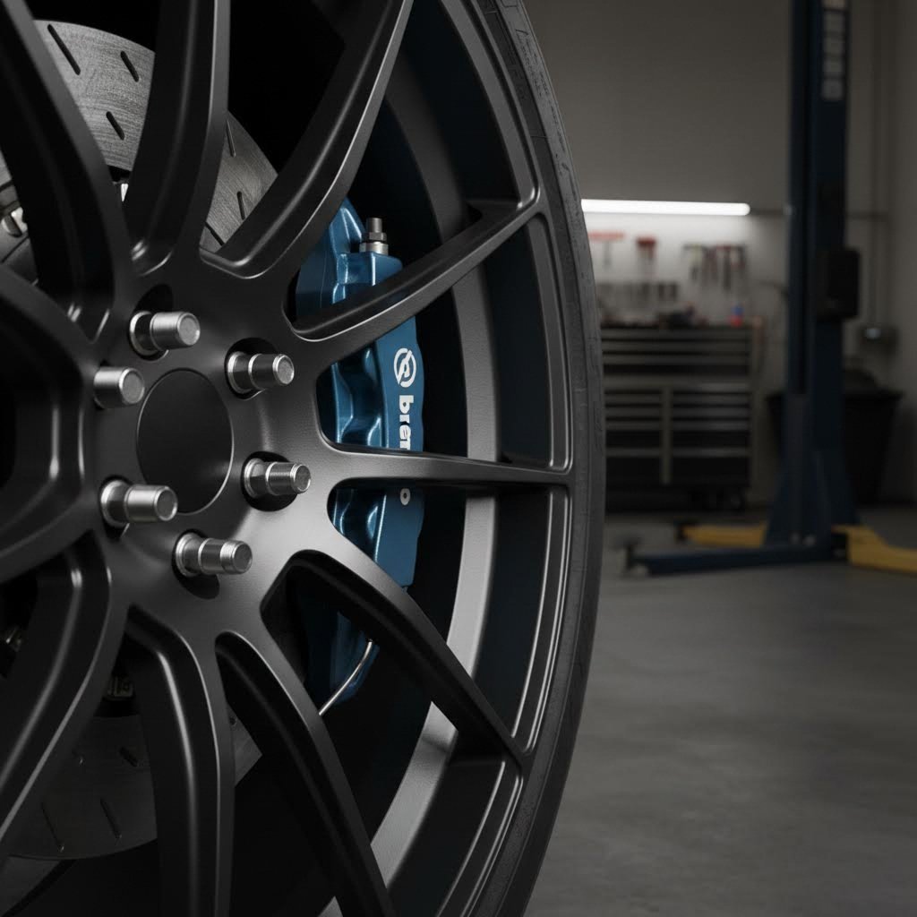
당신은 완벽한 단조 휠 세트를 찾았습니다. 마감 처리는 흠잡을 데 없고, 사양도 서류상으로는 정확해 보이며, 바로 장착하고 싶을 것입니다. 그런데 현실이 닥칩니다: 17인치 휠림이 브레이크 캘리퍼스를 피하지 못합니다. 무엇이 잘못된 걸까요? 그 해답은 '구매' 버튼을 누르기 전에 브레이크 간섭 여부를 정확히 이해하는 데 있습니다.
금속과 운동 사이의 결정적 간격
브레이크 간섭 방지는 휠 내면과 차량의 제동 부품 사이에 존재하는 물리적 공간을 의미합니다. 여기에는 휠 내부 배럴, 스포크, 그리고 캘리퍼스 본체, 로터 가장자리 및 마운팅 브라켓과 같은 핵심 브레이크 하드웨어 사이의 간격이 포함됩니다. 적절한 휠 간섭 여유가 없다면 새로 산 휠은 자유롭게 회전하지 못하거나 아예 장착조차 되지 않을 수 있습니다.
자동차의 핏먼트(fitment)를 고려할 때, 이를 3차원 퍼즐이라고 생각하십시오. 휠은 여러 방향으로 동시에 공간을 차지하는 부품들을 수용해야 합니다. 캘리퍼 몸체는 허브에서 바깥쪽으로 돌출되며, 로터는 원형 경로를 스윕합니다. 장착용 하드웨어는 다양한 각도로 돌출되어 있습니다. 이러한 요소들이 휠 내부의 공간에 맞춰져야 할 때, 매 밀리미터가 중요합니다.
브레이크 여유공간은 단일 치수 측정이 아니라 중심으로부터의 반경 거리, 허브면으로부터의 축 방향 깊이, 그리고 부품들이 공간을 통해 움직일 때 발생하는 회전 스윕까지 포함하는 3차원적 과제입니다.
휠 선택 시 왜 밀리미터가 중요한가
단조 휠은 주조 휠 가이드에서 종종 간과하는 독특한 고려사항을 수반합니다. 제조 공정 특성상 브레이크 시스템을 위한 여유 공간에 직접적인 영향을 미치는 설계 가능성을 제공합니다. 더 얇은 스포크 프로파일, 최적화된 배럴 형상, 정밀한 치수 제어는 단조 휠이 공간이 협소한 상황에서도 이점을 갖도록 해줍니다.
에 따르면 Velgen Wheels , 브레이크 클리어런스는 "적절한 휠 핏팅을 결정하는 가장 중요한 요소 중 하나이지만, 자주 간과되는 요소"입니다. 특히 고성능 브레이크 패키지나 멀티피스톤 캘리퍼를 갖춘 애프터마켓 대형 브레이크 키트를 장착한 차량의 경우 더욱 중요합니다.
이 가이드에서는 올바른 핏팅을 달성하기 위해 필요한 모든 내용을 안내합니다.
- 캘리퍼, 로터 및 휠 치수에 대한 정확한 측정 기술
- 주요 제조업체별 캘리퍼 사양
- 오프셋 계산법과 다양한 방향에서의 클리어런스에 미치는 영향
- 실제 운행 조건에서 호환성을 확인하기 위한 정적 및 동적 검증 방법
기존 브레이크 시스템에 단조 휠을 업그레이드하든, 완전한 브레이크 및 휠 패키지를 계획하든, 이러한 기본 원리를 이해하면 비용이 많이 드는 실수를 피할 수 있으며, 차량이 외관뿐 아니라 성능도 우수하게 작동하도록 보장할 수 있습니다.
단조 휠 구조가 클리어런스에 미치는 영향
큰 브레이크 키트를 장착할 때 일부 애호가들이 왜 단조 휠을 고집하는지 궁금한 적이 있나요? 그 이유는 단순히 외관이나 브랜드 프리미엄 이상으로 깊이 있습니다. 제조 공정 자체가 구조적 이점을 만들어내며, 이는 정확히 소중한 밀리미터 단위의 브레이크 클리어런스로 이어집니다. 이 밀리미터가 완벽한 착용과 좌절적인 반품 여부를 결정짓는 경우도 있습니다.
단조 휠과 주조 휠의 구조 및 클리어런스 의미
주조 휠은 용해된 알루미늄을 금형에 부어 만드는 것으로 시작됩니다. 피팅 인더스트리즈 중력 주조는 금속이 공동 안으로 흘러 들어가 자연스럽게 냉각되도록 하는 반면, 저압 주조는 양의 압력을 가해 알루미늄을 주입하여 더 빠르고 통제된 방식으로 채웁니다. 두 방법 모두 비용 효율적이지만, 느슨한 입자 구조를 형성하게 되어 충분한 강도를 확보하기 위해 더 두꺼운 재료가 필요합니다.
단조 휠은 완전히 다른 접근 방식을 취합니다. 제조업체는 먼저 알루미늄 덩어리(빌렛)를 사용하여 제어된 고온에서 가열합니다. 그런 다음 가열된 덩어리를 8,000~10,000톤의 압력으로 압축하여 금속의 결정 구조를 매우 조밀하고 균일한 패턴으로 만듭니다. 이 압축 공정을 통해 알루미늄 분자가 정렬되어 강도 대 무게 비율이 크게 향상됩니다.
이러한 특성이 브레이크 클리어런스 프로젝트에는 어떤 의미가 있을까요? 단조 휠은 더 두꺼운 주조 휠보다도 뛰어난 구조적 강성을 유지하면서도 스포크 두께를 얇게 만들 수 있습니다. 캘리퍼 본체 근처와 같은 핵심 부위에서 이는 추가로 3~5mm의 여유 공간을 확보할 수 있게 해 줍니다. 18인치 휠 안쪽에 6피스톤 브렘보 시스템을 장착하려 할 때, 이러한 밀리미터 단위의 여유는 매우 소중한 가치를 지닙니다.
- 결정립 구조 밀도: 단조 알루미늄은 강도를 희생하지 않으면서도 더 얇은 단면 두께를 가능하게 하는 밀집된 결정립 패턴을 특징으로 합니다
- 스포크 디자인 유연성: 엔지니어는 캘리퍼 바디에서 벗어나는 더 공격적인 스포크 각도와 프로파일을 설계할 수 있음
- 배럴 맞춤화 옵션: 내부 배럴 형상은 캘리퍼 포켓 깊이를 극대화하기 위해 정밀하게 가공될 수 있음
- 무게 분포 패턴: 전략적인 소재 배치를 통해 필요한 곳에 강도를 제공하면서 동시에 간섭이 민감한 구역에서는 무게를 제거함
제조 방식이 선택지에 미치는 영향
모든 단조 휠이 동일한 여유 공간 이점을 제공하는 것은 아닙니다. 세 가지 주요 제작 유형을 이해하면 브레이크 구성에 가장 적합한 디자인을 파악하는 데 도움이 됩니다.
모노블록 단조 휠 cNC 장비를 사용하여 단일 알루미늄 덩어리에서 가공됨. 따라서 Apex Wheels 설명하듯이, 이 구조는 강도, 강성, 그리고 무게 절감 사이에서 '비할 데 없는 균형'을 제공합니다. 브레이크 여유공간을 확보하기 위해 모노블록 디자인은 엔지니어들이 캘리퍼 공간을 침해하는 조인트나 조립 부속품 없이 인너 배럴의 형상을 최적화할 수 있도록 허용합니다. 볼트나 보강된 조립 플랜지가 없기 때문에 브레이크에 더 많은 공간을 제공할 수 있습니다.
두 파트 단조 휠 단조 중심 섹션을 별도의 배럴에 연결하는 방식으로, 일반적으로 용접을 통해 결합합니다. 이 모듈식 접근 방식은 오프셋과 너비 조합의 일부 맞춤화를 가능하게 합니다. 그러나 용접된 접합부는 인너 배럴의 형상을 특정 영역에서 공격적으로 설계하는 것을 제한할 수 있습니다.
쓰리피스 포지드 휠 배럴을 내부 및 외부 부분으로 분리하고 볼트나 용접으로 중심부에 연결합니다. 이러한 구조는 특수한 장착 요구사항에 최대한 맞춤화할 수 있게 해주지만, 특히 볼트 머리와 보강된 플랜지 같은 조립 부품들이 여유 공간을 줄일 수 있습니다. 3피스 구조는 트랙 사이드에서의 수리가 중요한 모터스포츠 응용 분야에서는 뛰어나지만, 제한된 캘리퍼 간격을 확보하려는 일반 도로 사용자들은 단체 가공된 모노블록 구조가 더 적합하다고 느낄 수 있습니다.
예산이 낮은 겨울용 구성의 16인치 스틸 휠과 비교해 보세요. 그런 스탬프 가공된 스틸 휠 디자인은 고정된 형상을 가지며 캘리퍼를 위한 유연성이 전혀 없습니다. 브렘보(Brembo)에서 OEM 업그레이드용으로 설계한 휠조차도 특정 간극 사양 내에서 작동하지만, 단조 후가공 옵션은 맞춤 설계를 통해 종종 이를 초과할 수 있습니다.
요약하면, 빅 브레이크 키트와 어울리는 휠을 구매할 때 휠의 제조 방식에 대해 묻는 것은 단순히 품질이나 무게 이상의 문제입니다. 이는 다피스톤 캘리퍼스를 위한 공간이 얼마나 되는지에 직접적인 영향을 미칩니다. 단조 방식의 중요성을 이제 이해했으므로, 실제로 필요한 여유 공간을 파악하기 위해 브레이크 시스템을 어떻게 정확히 측정해야 하는지 살펴보겠습니다.
휠 핏업을 위한 필수 브레이크 시스템 측정
캘리퍼스 여유 공간 확보를 위해 왜 단조 휠이 중요한지 이미 이해하셨습니다. 하지만 이러한 지식을 정확한 수치로 어떻게 전환할 수 있을까요? 브레이크 패드, 캘리퍼스 및 로터를 정확하게 측정하는 방법을 아는 것은 성공적인 휠 핏업 프로젝트의 기초입니다. 이제 브레이크 측정 과정 전체를 단계별로 나누어 설명하겠습니다.
브레이크 시스템 측정 단계별 가이드
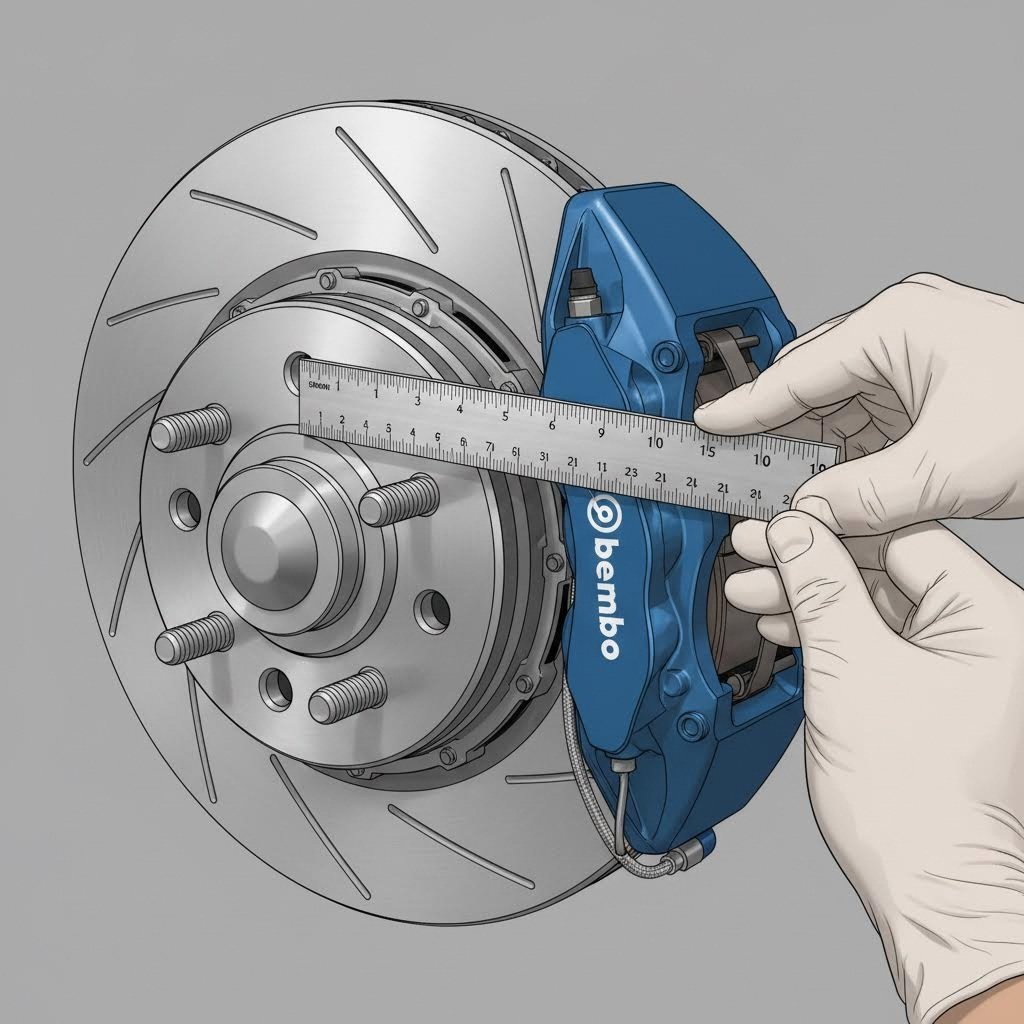
휠 구매를 시작하기 전에, 차량에서 정확한 브레이크 측정값을 얻어야 합니다. The Wheel Smith의 포괄적인 휠 핏업 가이드에 따르면 정확한 측정은 차량을 평지에서 지상으로 들어올리고 바퀴를 제거한 후, 허브의 마운팅 표면이 수직인지 확인하는 것으로 시작합니다. 약 30인치 길이의 견고한 직선 자를 사용하면 가장 정확한 결과를 얻을 수 있습니다.
브레이크 시스템을 3차원 공간을 차지하는 것으로 생각하십시오. 측정값에는 허브에서 외부로 얼마나 돌출되어 있는지, 중심에서 위로 얼마나 높이 올라가는지, 그리고 마운팅 표면을 따라 얼마나 넓게 퍼져 있는지를 모두 포함해야 합니다. 어느 한 축의 치수라도 빠지면 예상하지 못한 간섭이 발생할 수 있습니다.
모든 중요한 치수를 정확히 측정하기 위한 체계적인 방법은 다음과 같습니다:
- 허브 지름 측정: 이 값은 센터 보어 요구 사양을 결정하며 반경 방향 측정의 기준점을 제공합니다
- 허브 중심에서 캘리퍼 상단까지의 반경 측정: 허브 중심에서 캘리퍼 본체의 가장 높은 점까지 직선 자를 연장하세요—이 치수는 최소 휠 지름을 결정합니다
- 마운팅 표면에서 캘리퍼 외측 가장자리까지 측정: 스트레이트 에지를 허브 장착면에 대고 캘리퍼 본체의 가장 바깥쪽 끝까지 측정하여 축방향 여유 공간 필요량을 확인하십시오
- 장착면에서 허브 길이를 측정하십시오: 특히 전륜의 경우, 허브 어셈블리가 장착면을 기준으로 얼마나 돌출되는지 측정하십시오
- 장착면에서 펜더 가장자리까지 측정하십시오: 휠 오프닝의 가장 높은 지점에서, 프레임 장애물까지의 내측 거리와 펜더 리프까지의 외측 거리 모두를 측정하십시오
모든 애호가가 반드시 알아야 할 핵심 치수
브레이크 디스크와 캘리퍼를 측정하는 방법을 이해하려면 여러 접촉 지점을 주의 깊게 살펴야 합니다. 휠의 내부 배럴과 스포크는 캘리퍼 본체뿐 아니라 장착 이어, 브라켓 하드웨어, 로터의 외측 가장자리까지 모든 돌출부를 피해야 합니다.
| 측정 지점 | 측정해야 할 항목 | 왜 중요 합니까? |
|---|---|---|
| 캘리퍼 본체 폭 | 허브 장착면에서 캘리퍼 가장 바깥쪽 지점까지의 거리 | 최소 휠 백스페이스 요구량 결정 |
| 허브에서 캘리퍼 높이 | 허브 중심에서 캘리퍼 본체 상단까지의 반경 | 최소 휠 직경 설정 — 일반적으로 15-20mm 여유 공간 필요 |
| 로터 외경 | 브레이크 디스크 전체 지름을 가장자리에서 가장자리까지 측정 | 최소 휠 크기 호환성과 직접적인 연관 있음 |
| 로터 햇 높이 | 로터 마찰면에서 허브 장착면까지의 거리 | 휠 배럴 대비 캘리퍼 위치에 영향을 미침 |
| 장착 브래킷 돌출부 | 허브면에서 캘리퍼 장착 부품의 최대 돌출 길이 | 종종 간과되지만 휠 내측 배럴과 간섭될 수 있음 |
로터 지름은 휠 크기에 대한 절대적 제한을 결정하기 때문에 특별한 주의가 필요합니다. Alcon Brakes는 이 관계에 대해 명확한 가이드를 제공합니다. 343mm 로터는 최소 17인치 휠이 필요하며, 355mm 로터는 적어도 18인치 휠이 필요하고, 380mm 로터는 19인치 이상의 휠을 요구합니다. 400mm 이상의 로터 업그레이드를 계획 중이십니까? 대부분의 경우 최소 20인치 휠 직경이 필요합니다.
왜 로터 크기가 그렇게 중요한가요? 더 큰 로터는 고성능 주행에 있어 두 가지 핵심적인 이점을 제공합니다: 더 높은 제동 토크와 더 큰 열 용량입니다. Alcon이 설명하듯이, "작은 로터는 처음 몇 번은 매우 잘 멈추지만, 반복적인 강한 제동으로 열이 축적되면 큰 로터보다 성능 저하가 더 빨리 발생합니다." 다만, 큰 로터는 휠 사이즈 선택 폭을 제한하고 언스프렁 웨이트를 증가시킨다는 단점이 있습니다.
휠 백스페이스 측정 방법
백스페이스를 이해하는 것은 중요합니다. 백스페이스는 휠의 내부 배럴과 브레이크 부품 사이에 존재하는 공간을 직접적으로 결정하기 때문입니다. 백스페이스는 휠의 마운팅 표면에서부터 휠 배럴의 안쪽 가장자리까지의 거리를 측정합니다.
기존 휠의 백스페이스를 측정하려면 다음을 따르세요:
- 휠을 평평한 표면 위에 앞면이 아래로 향하게 놓으세요
- 휴일 배럴 뒷면 전체에 곧은 자를 올려놓으세요
- 곧은 자에서 허브 마운팅 패드까지 아래로 거리를 측정하세요
- 이 인치 단위의 거리가 바로 귀하의 백스페이스 측정값입니다
백스페이스가 클수록 휠의 내부 배럴이 브레이크 부품에 더 가까이 위치하게 됩니다. 백스페이스가 작아지면 배럴이 바깥쪽으로 밀려나며 캘리퍼 클리어런스는 늘어나지만, 동시에 휠의 앞면이 펜더에서 더 멀어집니다. 최적의 지점을 찾기 위해서는 브레이크 클리어런스와 서스펜션 기하학 및 펜더 적합성 사이의 균형을 맞추어야 합니다.
휠 구매를 고려할 때 백스페이스와 오프셋을 비교하려면 다음 관계를 사용하세요: 양의 오프셋 값이 높을수록 백스페이스가 더 크며, 낮거나 음의 오프셋 값은 백스페이스를 줄입니다. 동일한 너비의 휠에서 ET45는 ET35보다 캘리퍼 쪽으로 인너 배럴이 더 많이 돌출됩니다.
이러한 브레이크 치수 정보를 바탕으로 특정 캘리퍼와 휠 조합이 호환되는지 평가할 수 있습니다. 다음으로 주요 제조사들의 인기 있는 브레이크 캘리퍼 제품군 사양과 해당 최소 휠 요구사항을 살펴보겠습니다.
브레이크 캘리퍼 사양 및 최소 휠 요구사항
브레이크 시스템을 측정하고 백스페이스 계산 방법을 이해하셨습니다. 이제 실질적인 질문이 남았습니다. 어떤 캘리퍼스가 어느 휠 뒤에 맞는가? 캘리퍼스 브레이크 도면을 검토할 때, 서로 다른 제조업체들이 캘리퍼스를 각기 다른 본체 치수, 장착 위치 및 전체 외형으로 설계하고 있다는 것을 알 수 있습니다. 이러한 차이점은 곧바로 최소한의 휠 요구 사양을 결정합니다.
제조업체별 캘리퍼스 치수
애프터마켓 브레이크 산업에서는 수십 가지의 캘리퍼스 옵션을 제공하지만, 성능 중심 응용 분야에서는 Brembo, AP Racing, Wilwood, StopTech 네 곳의 제조업체가 주도하고 있습니다. 각 회사는 휠 호환성에 영향을 미치는 특정 치수 특성을 갖도록 캘리퍼스를 설계합니다.
위에서 디스크 브레이크 캘리퍼 다이어그램을 본다고 상상해 보세요. 캘리퍼 본체는 로터 가장자리를 감싸며, 피스톤이 브레이크 패드를 디스크 양면에 밀어붙입니다. 허브 중심에서부터 얼마나 뻗어나가는지에 해당하는 캘리퍼의 방사형 높이(radial height)는 최소 휠 지름을 결정합니다. 허브 표면에서부터 얼마나 돌출되는지에 해당하는 축방향 너비(axial width)는 백스페이스 요구사항을 결정합니다.
| 제조업체 | 캘리퍼 모델 시리즈 | 피스톤 구성 | 일반적인 최소 휠 지름 | 권장 오프셋 범위 |
|---|---|---|---|---|
| Brembo | GT / GT-R 시리즈 | 4기동 | 17 인치 | ET35-ET50 |
| Brembo | GT / GT-R 시리즈 | 6-피스톤 | 18인치 | ET38-ET52 |
| Brembo | GT-S / 레이싱 | 8피스톤 | 19인치 | ET40-ET55 |
| AP Racing | Radi-CAL CP9660 | 6-피스톤 | 18인치 | ET35-ET48 |
| AP Racing | Radi-CAL CP9668 | 6-피스톤 | 19인치 | ET38-ET50 |
| Wilwood | Superlite 4R | 4기동 | 17 인치 | ET32-ET45 |
| Wilwood | AERO6 / W6A | 6-피스톤 | 18인치 | ET35-ET48 |
| StopTech | ST-40 | 4기동 | 17 인치 | ET35-ET50 |
| StopTech | ST-60 | 6-피스톤 | 18인치 | ET38-ET52 |
중요한 안내: 이 수치들은 일반적인 요구 사항을 나타내며, 귀하의 특정 용도에 대해 제조업체 사양과 반드시 확인해야 합니다. 로터 지름, 차량 플랫폼 및 휠 설계는 모두 실제 여유 공간(clearance)에 영향을 미칩니다. 한 차량에서는 맞는 캘리퍼스와 휠 조합이라도 동일한 캘리퍼스 모델임에도 불구하고 다른 차량에는 맞지 않을 수 있습니다.
브레이크 킷을 휠 사양에 맞추는 방법
왜 많은 애호가들이 17인치 림을 구입한 후 브레이크 캘리퍼스를 위한 충분한 여유 공간이 없음을 알게 되는 것일까요? 그 이유는 대개 피스톤 수, 로터 크기, 캘리퍼스 본체 치수 간의 관계를 간과하기 때문입니다.
다음은 그 패턴입니다: 일반적으로 피스톤이 많을수록 캘리퍼스 본체도 더 커집니다. 4피스톤 캘리퍼스는 보통 크기의 패드 면적에 걸쳐 클램핑력을 분산시킵니다. 6피스톤 설계로 넘어가면 추가 피스톤과 더 큰 패드를 수용하기 위해 캘리퍼스 본체가 커집니다. 8피스톤의 거대한 캘리퍼스는 더욱 넓은 공간을 필요로 하여 최소 휠 지름 요구 사양을 더욱 높입니다.
그러나 피스톤 수만으로는 전체적인 상황을 파악할 수 없습니다. 로터 지름도 동일하게 중요한 역할을 합니다. 4피스톤 캘리퍼를 355mm 로터와 함께 사용하면 바퀴 크기가 18인치 이상이어야 하지만, 같은 캘리퍼라도 330mm 로터와 함께 사용하면 17인치 바퀴에서도 충분한 여유가 있을 수 있습니다. 더 큰 스윕 반지름의 로터는 허브에 캘리퍼가 더 높은 위치에 장착되도록 만들어 휠 스포크와의 간섭 여부에 영향을 미칩니다.
간섭 문제를 방지하려면 다음 계획 접근법을 따르십시오.
- 원하는 캘리퍼 모델과 로터 지름 조합을 확인하십시오.
- 해당 정확한 조합에 대해 제조업체에서 제공하는 최소 휠 지름 사양을 확인하십시오.
- 스포크 디자인의 차이를 고려하여 15~20mm의 안전 마진을 추가하십시오.
- 대상 휠의 오프셋 값이 권장 범위 내에 있는지 확인하십시오.
- 주문 전 캘리퍼 사양을 휠 제조업체에 문의하십시오.
많은 애호가들이 모든 17인치 휠이 동일한 내부 여유공간을 제공한다고 착각하는 경우가 많습니다. 실제로는 스포크 디자인, 배럴 깊이, 오프셋 차이로 인해 캘리퍼 포켓의 크기가 현저히 달라질 수 있습니다. 음극 오프셋이 강한 딥디쉬 17인치 휠은 6피스톤 캘리퍼를 장착할 수 있지만, 양극 오프셋이 큰 평면형 17인치 휠은 동일한 캘리퍼를 장착할 수 없는 경우가 있습니다.
이로부터 얻을 수 있는 교훈은? 휠 직경만으로 캘리퍼 여유공간이 보장된다고 가정해서는 안 된다는 것입니다. 오프셋 값이 특정 브레이크 구성과 어떻게 상호작용하는지 이해하는 것이 필수적이며, 바로 다음 섹션에서 이를 자세히 다룰 것입니다.
휠 오프셋과 볼트 패턴이 여유공간에 미치는 영향
캘리퍼의 치수와 최소 휠 요구 사항을 확인하셨습니다. 하지만 많은 애호가들이 여기서 실수를 범합니다: 휠 직경만 맞추면 여유 공간 문제는 해결된다고 가정하는 것입니다. 실제로는 ET 휠 오프셋이 브레이크와 휠이 서로 간섭 없이 공존할 수 있는지 여부를 결정하는 데 동일하게 중요한 역할을 합니다. 오프셋 값이 실제 여유 공간으로 어떻게 전환되는지 살펴보고, 왜 이 단 하나의 숫자를 변경하면 휠 착용 상태에 여러 방향에서 영향을 미치는지 알아보겠습니다.
브레이크 여유 공간을 위한 ET 값 해석
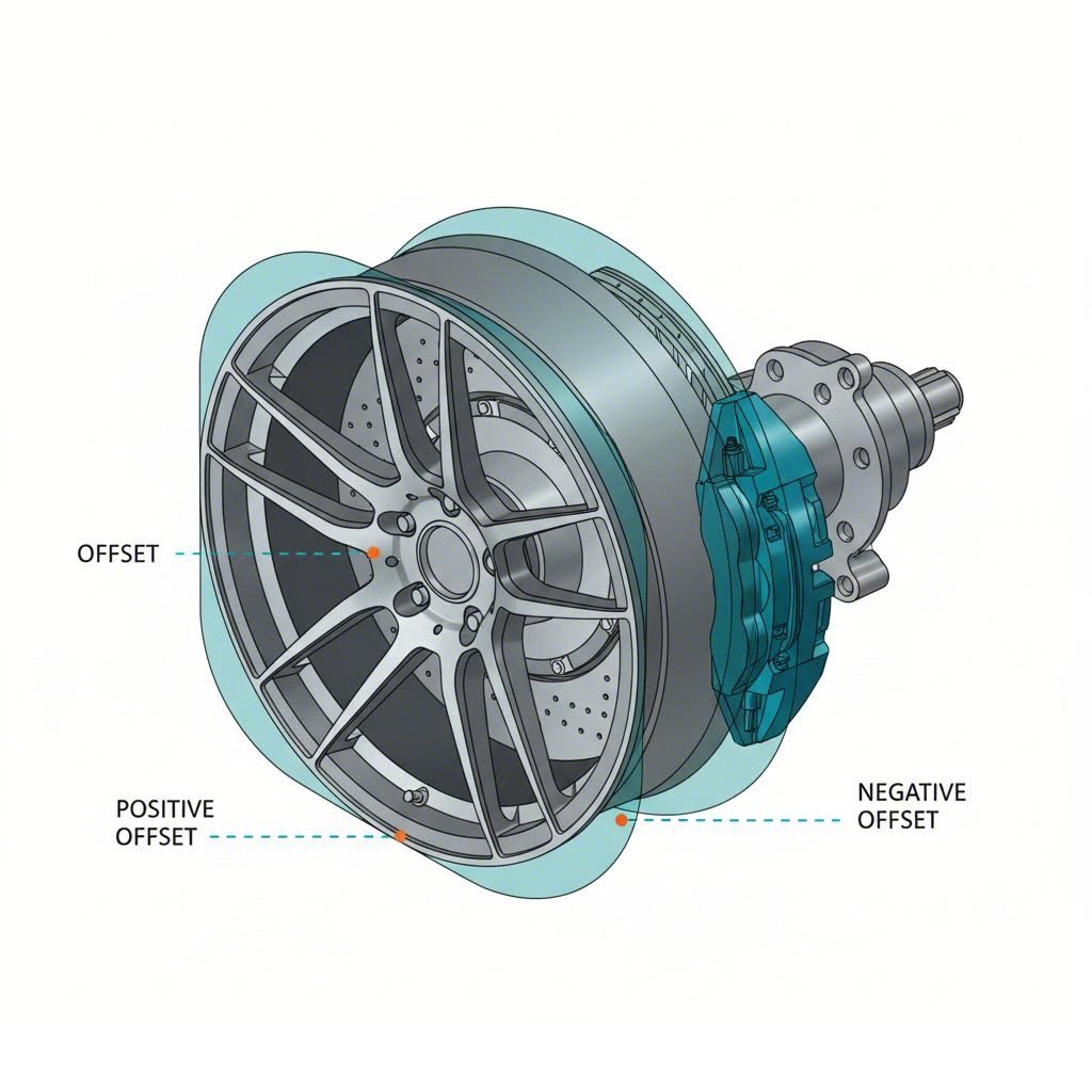
ET 오프셋이 정확히 무엇입니까? 이 용어는 독일어 'Einpresstiefe'에서 유래했으며, 삽입 깊이를 의미합니다. 휠의 허브 장착면과 휠 중심선 사이의 밀리미터 단위 거리를 측정합니다. 보기에는 단순해 보이는 이 숫자가 서스펜션, 브레이크 및 차체에 상대적인 전체 휠 어셈블리의 위치를 조절합니다.
오프셋 값이 실제로 작동하는 방식은 다음과 같습니다:
- 양의 오프셋 (ET35, ET45 등): 허브 장착면이 휠의 외측 면에 더 가까이 위치하여 휠을 서스펜션 쪽으로 안쪽으로 밀어냅니다. 이렇게 하면 휠 내측 림과 캘리퍼 본체 사이의 간격이 넓어져 대형 브레이크의 여유 공간 확보에 유리합니다
- 제로 오프셋(ET0): 장착면이 휠 중심선과 정확히 일치하여 양쪽에 균등한 간격을 만듭니다
- 음의 오프셋(ET-10, ET-20 등): 장착면이 내측 림 쪽으로 이동하여 휠을 허브에서 바깥쪽으로 밀어냅니다. 이는 내측 여유 공간을 줄이면서도 공격적인 '딥 디쉬(deep dish)' 외관을 만들어냅니다
수학적 관계는 간단합니다. 오프셋이 1mm 변화할 때마다 약 1mm의 여유 공간 변화가 발생합니다. ET45에서 ET35 휠로 교체하면 내측 림이 캘리퍼 방향으로 10mm 더 가까워집니다. 동일한 변경으로 인해 휠의 외측 면은 펜더에서 10mm 더 멀어지게 됩니다.
완벽한 맞춤을 위한 오프셋 계산식
많은 브레이크 측정 차트에서 명확히 설명하지 않는 점은 다음과 같습니다: 오프셋(offset)은 방사상 및 축상 여유 간격에 각각 다르게 영향을 준다는 것입니다. 이러한 차이를 이해하면 조립 중에 번거로운 시행착오를 방지할 수 있습니다.
축 방향 간격 축과 평행하게 측정되는 간격을 의미하며, 본질적으로 휠 배럴이 캘리퍼 바디로부터 얼마나 떨어져 있는지를 나타냅니다. 오프셋의 변화는 이 치수에 직접적인 영향을 미칩니다. 양의 오프셋이 낮아지거나(또는 음의 오프셋일 경우) 휠 내측 배럴이 캘리퍼 외면에서 멀어지면서 축상 여유 간격이 증가합니다.
반경 방향 간격 허브 중심에서 스포크나 배럴의 간섭이 발생하는 가장 가까운 지점까지의 거리를 의미합니다. 이 치수는 주로 휠 직경과 스포크 설계에 의해 결정되며, 오프셋과는 무관합니다. ET35인 17인치 휠은 ET45인 17인치 휠과 동일한 방사상 여유 간격을 제공합니다. 두 경우 모두 허브 중심에서 캘리퍼의 높이만큼을 확보해야 하기 때문입니다.
이것이 중요한 이유는 무엇일까요? 만약 클리어런스 문제가 캘리퍼 몸체가 휠의 내부 배럴에 닿는 것이라면, 오프셋 조정으로 문제를 해결할 수 있습니다. 하지만 스포크가 캘리퍼 상단에 닿고 있다면 더 큰 휠 지름이 필요하며, 아무리 오프셋을 변경해도 소용이 없습니다.
볼트 패턴 및 허브 보어 고려 사항
오프셋 사양을 최종 결정하기 전에, 휠이 차량의 볼트 패턴과 일치하는지 확인해야 합니다. 많은 스바루와 폭스바겐에서 사용하는 5x100과 다수의 일본 및 미국 차량에 표준인 5x114.3 같은 일반적인 패턴은 서로 교환할 수 없습니다. 오프셋과 지름이 종이상으로 얼마나 완벽하더라도, 5x100 휠은 5x114.3 허브에 장착될 수 없습니다.
허브 보어(센터 보어라고도 함)는 또 다른 중요한 점검 항목입니다. 휠의 중심 구멍은 차량의 허브 지름과 일치하거나 초과해야 올바르게 센터링됩니다. 중심 구멍이 더 큰 휠의 경우 허브 센트릭 링이 필요하며, 이는 진동을 제거하고 휠이 러그 너트가 아닌 허브 위에 정확히 중심을 이루도록 보장합니다.
기하학적 구조와 클리어런스의 균형 조정
단순히 캘리퍼 클리어런스를 위해 오프셋을 낮게 설정하면 그만이라는 말처럼 들릴 수 있지만, 실제로는 그렇지 않다. 모든 오프셋 변경은 차량의 주행 특성에 영향을 미치는 트레이드오프를 수반한다:
- 스크러브 반경의 변화: 휠을 바깥쪽으로 이동하면 조향 기하학이 달라져 조향력이 증가할 수 있으며 조향 피드백에 영향을 줄 수 있다
- 휀더 클리어런스 감소: 낮은 오프셋은 휠의 외측 면이 휀더에 더 가까워지게 만들어, 캘리퍼는 피하더라도 서스펜션 압축 시 휀더와 간섭이 발생할 수 있다
- 베어링 부하 증가: 극단적인 네거티브 오프셋을 가진 휠은 휠 베어링에 더 큰 레버리지를 가하게 되어 베어링 마모를 가속시킬 수 있다
- 서스펜션 스트레스: 스크러브 반경과 트랙 폭의 변화는 코너링 및 제동 중 서스펜션 부하에 영향을 준다
최적의 위치는 여러 요구 사항을 균형 있게 충족해야 합니다: 내측에는 적절한 캘리퍼 클리어런스, 외측에는 충분한 펜더 클리어런스, 그리고 서스펜션 기하 구조에 대한 수용 가능한 변화가 필요합니다. 대부분의 일반 도로 주행 용도에서는 차량의 순정 오프셋에서 10~15mm 이내를 유지하는 것이 합리적인 기하 구조를 유지하면서 업그레이드된 브레이크를 장착할 수 있는 여유 공간을 제공합니다.
오프셋 계산 방법을 이해했다면, 이제 브레이크 시스템 요구 조건에 맞춰 휠 사양을 평가할 수 있는 준비가 된 것입니다. 그러나 정적 측정값만으로는 전체 상황의 일부만을 알 수 있습니다. 실제로는 서스펜션이 움직이고, 스티어링이 회전하며, 브레이크는 열을 발생시킵니다. 다음으로는 실제 운행 조건에서 다이내믹한 상태로 클리어런스를 확인하는 방법을 살펴보겠습니다.
정적 대비 동적 클리어런스 검증 방법
당신은 오프셋을 계산하고 캘리퍼스를 측정했으며, 종이상의 수치는 완벽해 보입니다. 하지만 많은 애호가들이 예상치 못하는 현실이 있습니다: 서스펜션이 압축되고, 스티어링이 회전하며, 브레이크는 달아오릅니다. 정적 측정값은 동적인 시스템의 한 순간만을 포착할 뿐입니다. 올바른 적합도를 이해하려면 차량이 고요히 주차된 상태가 아니라 실제 운행 조건에서 테스트해야 합니다.
정적 측정을 넘어서
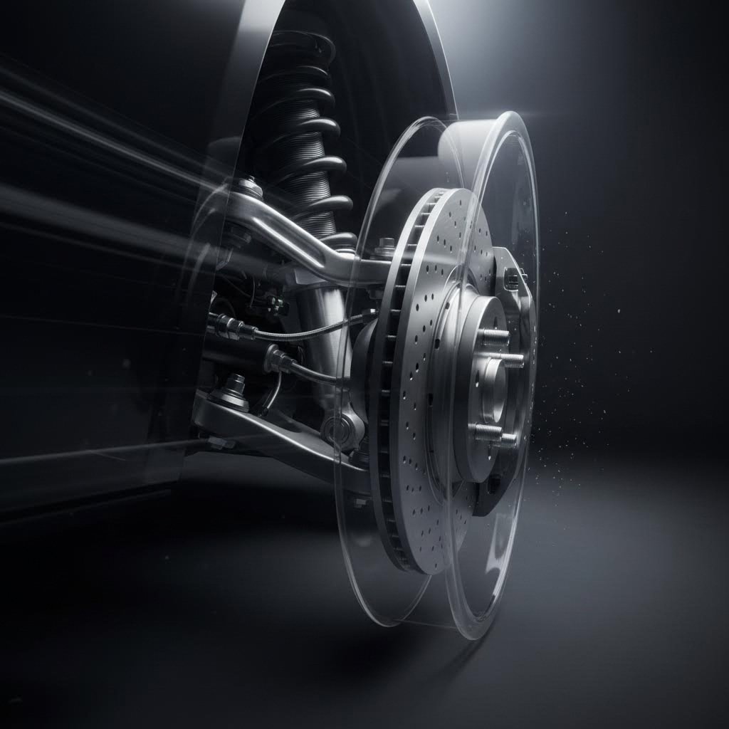
과속 방지턱을 지나거나 급격한 코너를 돌 때 어떤 일이 일어나는지 생각해보세요. 서스펜션이 압축되면서 휠과 브레이크 부품 간의 관계가 변합니다. 완전히 압축된 상태에서는 휠이 섀시에 대해 위쪽으로 이동하지만, 브레이크 캘리퍼스는 컨트롤 암을 따라 움직입니다. 이러한 움직임으로 인해 주차된 차량에서는 충분한 여유 공간이 있는 것처럼 보였던 캘리퍼스 본체와 휠 스포크 사이의 거리가 위험할 정도로 좁아질 수 있습니다.
자동차의 브레이크 시스템 다이어그램은 구성 부품들이 정지 상태일 때의 위치를 보여줍니다. 그러나 실제 적용 시에는 서스펜션이 움직이는 전체 범위를 고려해야 합니다. 가속 중 무게 이동, 급제동, 코너링 하중 시 스프링이 압축되며, 반동 시 및 서스펜션이 언덕이나 골짜기 위를 지날 때 처짐이 발생하면 스프링이 늘어납니다.
조향각도는 또 다른 변수를 추가합니다. 핸들을 한쪽 끝에서 다른 쪽 끝까지 꺾을 때, 앞쪽 브레이크 캘리퍼가 허브 어셈블리와 함께 회전합니다. 직진 상태에서 휠의 내측 배럴과 간섭이 없었던 캘리퍼가 조향 각도가 최대일 때는 배럴에 닿을 수 있습니다. 이는 특히 회전 반경이 좁거나 공격적인 조향각을 갖는 차량에서 문제가 될 수 있습니다.
서스펜션 및 조향 역학 고려
휠과 브레이크 조합을 확정하기 전에 다음 포괄적인 검증 절차를 반드시 거치십시오:
- 정적 간극 확인: 차량을 평지에 위치시키고 서스펜션을 정상 주행 높이로 맞춘 상태에서 휠 표면과 모든 브레이크 부품 사이의 간격이 최소 3~5mm 이상인지 확인하십시오. 휠을 천천히 회전시키며 여러 스포크 위치에서 점검하십시오.
- 완전 압축 테스트: 쇼크 업소버를 제거하거나 래칫 스트랩을 사용하여 서스펜션을 완전히 들어올린 상태(풀범프)로 당기십시오. 모든 스포크 위치에서 다시 간격을 확인하십시오. 이는 급격한 코너링이나 울퉁불퉁한 노면 충격 시에만 발생하는 간섭을 확인할 수 있습니다.
- 완전 드롭 테스트: 차체 프레임을 지지한 상태에서 서스펜션이 최대 신장된 상태로 자유롭게 늘어지도록 하십시오. 워ashboard 노면이나 속도 저감 장치(스피드 범프)를 통과할 때 발생할 수 있는 리바운드 상황에서도 접촉이 없음을 확인하십시오.
- 스티어링 잠금 테스트: 서스펜션이 주행 높이 및 완전 압축 상태일 때, 스티어링 휠을 좌우 양쪽 방향으로 완전히 회전시키십시오. 잠금 위치뿐 아니라 전체 조향 궤적을 따라 간격을 점검하십시오.
- 열 순환 고려사항: 과격한 주행 중 열 팽창을 고려하여 기계적 여유공차보다 2~3mm의 안전 마진을 추가하십시오. 브레이크 디스크와 캘리퍼는 열이 오르면 팽창하여 냉각 상태에서의 측정값보다 여유공차가 줄어듭니다.
서킷 주행이나 산악 도로에서 역동적인 주행 시에는 열 팽창에 특별한 주의가 필요합니다. 강한 제동 시 주철 디스크는 약 0.5~1mm 정도 직경 방향으로 팽창하며, 알루미늄 캘리퍼 본체는 모든 방향으로 약간 확장됩니다. 이러한 변화는 미미해 보일 수 있지만, 충분했던 여유공차가 일시적인 접촉으로 이어져 휠과 캘리퍼 표면을 손상시킬 수 있습니다.
피해야 할 일반적인 측정 오류
신중한 애호가라도 실수를 하여 여유공차 문제를 겪을 수 있습니다. 다음의 함정들을 주의 깊게 살펴보세요.
- 마모된 부품으로 측정하기: 새 브레이크 패드와 디스크는 마모된 것과 위치가 다릅니다. 패드 수명이 50% 남은 차량을 측정할 경우, 새 패드는 캘리퍼 피스톤을 더 바깥쪽으로 밀어내어 여유공차를 줄입니다.
- 캘리퍼 브래킷 하드웨어 무시하기: 볼트 머리와 브래킷 가장자리는 종종 메인 캘리퍼 본체를 벗어나 돌출되어 있습니다. 캘리퍼 하우징만이 아니라 가장 바깥쪽 끝까지 측정해야 합니다
- 휠 무게 밸런싱을 잊는 것: 클립온 또는 접착식 휠 웨이트는 인너 배럴에 두께를 추가합니다. 제한된 여유 공간 계산 시 웨이트의 위치를 반드시 고려해야 합니다
- 단일 지점에서만 확인하는 것: 휠은 완벽하게 원형이 아니며, 캘리퍼는 특정 위치에 장착됩니다. 여러 스포크 위치에서 여유 공간을 점검할 때 휠을 한 바퀴 완전히 회전시켜야 합니다
OEM 브레이크 업그레이드의 경우 — 예를 들어 상위 트림 레벨의 더 큰 공장용 로터를 장착하는 것 — 검증 과정이 일반적으로 간단합니다. 이러한 부품들은 공장 사양의 허용 오차 내에서 설계되었으며 보통 OEM 사양의 휠과 호환되기 때문입니다. 그러나 항상 사용하려는 특정 휠 모델과의 여유 공간을 반드시 확인해야 합니다
애프터마켓 빅 브레이크 키트 설치는 더욱 엄격한 테스트를 요구합니다. 멀티피스톤 캘리퍼는 종종 OEM 유닛과 다른 각도로 장착됩니다. 더 큰 로터는 캘리퍼의 반경 방향 위치를 변경합니다. 일부 키트에는 공장 구성보다 캘리퍼 본체를 더 바깥쪽으로 배치하는 캘리퍼 브라켓이 포함되어 있습니다. OEM 브레이크를 피한 휠이 애프터마켓 업그레이드에도 자동으로 호환된다고 가정해서는 안 됩니다.
동적 검증이 완료되면, 특정 차량 및 브레이크 구성에 맞는 올바른 휠 크기를 선택할 수 있습니다. 다음 섹션에서는 일반적인 플랫폼 전반에 걸쳐 실용적인 사이징 가이드를 제공하여 휠 지름을 브레이크 요구사항에 맞추는 방법을 안내합니다.
차량 플랫폼별 휠 사이즈 선정
측정값을 확인하고 오프셋을 계산한 후 동적 여유 공간도 검증했습니다. 이제 실질적인 결정을 내릴 차례입니다: 어떤 휠 지름이 귀하의 차량과 브레이크 구성에 실제로 적합할까요? 휠 사이징은 만능 솔루션이 아닙니다. 도심형 차량에는 완벽하게 맞는 16인치 스틸 휠이라도 트랙 중심의 차량에 사용되는 355mm 로터를 수용할 수는 없습니다. 인기 있는 플랫폼과 용도별로 휠 사이즈 선택지를 살펴보겠습니다.
일반적인 용도에 맞는 휠 사이즈 선택
휠 지름은 브레이크 여유 공간 계산의 기초가 됩니다. 큰 휠일수록 캘리퍼를 수용하기 위한 내부 배럴 공간이 넓어지지만, 작은 휠은 브레이크 업그레이드 가능성을 제한합니다. 그러나 더 크다고 해서 항상 더 좋은 것은 아닙니다. 타이어 공급 가능성, 승차감, 비탄성 중량 등도 모두 고려해야 할 요소입니다.
| 휠 직경 | 일반적인 브레이크 로터 호환성 | 일반적인 차량 적용 사례 | 여유 공간 고려사항 |
|---|---|---|---|
| 15인치 | 최대 280mm 로터 | 경량 스포츠카, 빈티지 차량, 오토크로스 차량 | OEM 크기 이하의 브레이크로 제한; 4피스톤 캘리퍼는 거의 맞지 않음 |
| 16 인치 | 280mm-310mm 로터 | 토요타 코롤라, 혼다 시빅, 스바루 임프레자, 경제형 트럭 | 대부분의 OEM 브레이크 패키지를 수용 가능; 애프터마켓 4피스톤 업그레이드는 여유가 적음 |
| 17 인치 | 310mm-343mm 로터 | 토요타 캠리, 스바루 WRX, 혼다 어코드, 중형 트럭 | 적절한 오프셋으로 대부분의 4피스톤 키트가 장착 가능한 중간 수준의 브레이크 업그레이드에 이상적 |
| 18인치 | 343mm-365mm 로터 | 고성능 세단, 머슬카, 대형 트럭 | 대부분의 6피스톤 캘리퍼를 수용 가능; 일반적인 대형 브레이크 키트의 시작점 |
| 19인치 이상 | 365mm-400mm+ 로터 | 고성능 차량, 럭셔리 SUV, 전용 트랙 차량 | 대형 멀티피스톤 브레이크 구성에 필요; 뛰어난 청소공간을 제공하지만 타이어 선택 폭이 줄어듦 |
브레이크 구성에 맞는 휠 지름 선택
Corolla 또는 Camry용 토요타 16인치 휠을 찾고 계신가요? 이러한 휠은 일반적으로 순정 브레이크 구성과 문제없이 호환되므로 일상 주행 및 겨울용 타이어 구성에 이상적입니다. 토요타의 보수적인 순정(OEM) 브레이크 크기는 16인치 휠 내에서 대부분의 응용 사례에 충분한 여유 공간을 제공합니다.
16인치 슈바루 휠을 구매하려는 슈바루 오너의 경우 보다 제한된 조건을 마주하게 됩니다. 많은 WRX 및 STI 모델은 더 큰 순정 캘리퍼를 장착하여 최소 휠 지름을 17인치로 높이고 있습니다. 기본 Impreza 모델은 일반적으로 16인치 휠과 호환되지만, 구매 전에 본인 차량의 구체적인 브레이크 사양을 반드시 확인해야 합니다.
16인치 혼다 휠을 찾는 혼다 애호가들은 시빅 및 핏 모델과의 호환성이 우수한 것을 알 수 있습니다. 어코드 및 더 큰 플랫폼은 특히 강화된 브레이크 시스템을 갖춘 스포츠 및 투어링 트림의 경우, 공장에서 지정한 브레이크 여유 공간을 확보하기 위해 최소 17인치 이상이 자주 필요합니다.
지엠씨 트럭에 16인치 휠을 장착하려는 트럭 구매자는 차량이 표준 브레이크 패키지인지 강화된 브레이크 패키지를 갖추고 있는지 반드시 확인해야 합니다. 대형 내구성 모델이나 견인용 패키지를 장착한 차량은 종종 더 큰 캘리퍼를 탑재하여 17인치 이상의 휠을 요구하는 경우가 많습니다.
다운사이징 대 업사이징: 상충 요소
휠 직경 다운사이징을 고려해야 할 시점은 언제일까요? 겨울용 타이어 세트 및 전용 트랙 휠의 경우 보통 더 작은 직경이 유리합니다:
- 겨울용 타이어의 가용성: 작은 사이즈의 고품질 겨울용 타이어는 19인치나 20인치 옵션보다 더 다양한 선택과 낮은 가격을 제공합니다
- 측면 벽 보호: 작은 휠은 더 긴 측면 벽과 함께 사용될 경우 도로의 움푹 들어간 부분 충격을 더 잘 흡수하여 타이어와 휠 자체를 보호합니다
- 비현중량 감소: 지름이 작은 휠은 무게가 가볍기 때문에 서스펜션 반응성과 승차감이 향상됩니다
- 서킷 데이 실용성: 많은 전문적인 서킷 애호가들은 타이어 컴파운드 선택 폭을 넓히고 교체 비용을 절감하기 위해 17인치 또는 18인치 휠을 사용합니다
브레이크 업그레이드 시 현재 장착된 휠의 여유 공간을 초과하게 되면 휠 사이즈를 키워야 할 필요가 생깁니다. 큰 브레이크 키트 설치를 계획 중이라면, 먼저 측정하고 그에 맞는 휠 지름을 선택하세요. 바로 19인치 이상으로 넘어가면 여유 공간은 확보되지만 타이어 선택 폭이 제한되고 비용도 증가합니다
강철 휠 고려 사항
예산을 고려하는 애호가들은 종종 강철 휠이 자신의 용도에 적합한지 묻곤 합니다. 강철 휠은 겨울용으로 사용 시 비용 효율성과 뛰어난 내구성을 제공하지만, 고유한 청소 여유 공간 문제를 동반할 수 있습니다
스포크 디자인과 맞춤형 베럴 깊이가 최적화된 단조 휠과 달리, 스틸 휠은 표준화된 프레스 성형 구조를 특징으로 합니다. 내부 베럴의 형상 때문에 캘리퍼스 장착 공간이 거의 없어, 한 차량에서 순정 브레이크와 간섭 없이 작동하는 16인치 스틸 휠이라도 다른 플랫폼에서는 베럴 깊이 및 스포크 간섭 거리의 미세한 차이로 인해 동일한 브레이크와 간섭이 발생할 수 있습니다.
빅 브레이크 키트 적용 시 스틸 휠은 거의 사용할 수 없습니다. 고정된 내부 형상으로 인해 단조 또는 주조 애프터마켓 휠처럼 캘리퍼 포켓을 맞춤 제작할 수 없기 때문입니다. 스틸 휠은 차량 제조사에서 간섭 여부를 이미 검증한 순정 브레이크 구성에만 사용하는 것이 좋습니다.
휠 사이징을 이해하는 것은 최종 계획 수립을 위한 기반을 마련합니다. 직경 요구 사항을 명확히 한 후에는 단조 휠과 브레이크 조합이 처음부터 완벽하게 맞도록 보장하는 전체 구매 전 체크리스트를 진행할 준비가 된 것입니다.
단조 휠 및 브레이크 간섭 여부 설정 계획
당신은 측정값을 수집하고, 캘리퍼스 사양을 분석하며 오프셋이 여유 공간에 어떤 영향을 미치는지 이해했습니다. 이제 이러한 지식을 체계적인 계획으로 전환하여 비용이 큰 실수를 방지할 차례입니다.판매 중인 16인치 림을 살펴보거나 대형 브레이크 키트용 맞춤형 19인치 단조 휠 세트를 설계하든, 적절한 계획 수립은 성공적인 작업과 좌절스러운 반품 사례를 가르는 핵심 요소입니다.
구매 전 여유 공간 점검 목록
휠과 브레이크 핏먼트를 구입하기 전 모든 조각이 정확히 맞아야 하는 퍼즐이라고 생각하세요. 이 과정을 서두르거나 외관이 완벽해 보인다는 이유로 단계를 건너뛰면 본 가이드에서 다룬 여유 공간 문제들이 발생하게 됩니다. 숙련된 작업자들이 따르는 체계적인 작업 순서는 다음과 같습니다.
- 브레이크 시스템의 전체 사양을 수집하세요: 캘리퍼 모델, 피스톤 구성, 로터 지름 및 로터 해트 높이를 문서화하십시오. 애프터마켓 대형 브레이크 키트의 경우 캘리퍼 본체 치수와 마운팅 브래킷 돌출부를 보여주는 제조업체의 기술 도면을 확보하십시오. 일반 사양에 의존하지 말고, 귀하의 특정 키트 및 차량 적용을 위한 정확한 치수를 확보하십시오.
- 최소 휠 요구사항 계산: 브레이크 사양을 기반으로 최소 휠 지름, 필요한 백스페이스 범위 및 허용 가능한 오프셋 범위를 결정하십시오. 스포크 디자인의 변동성과 동적 여유 공간 필요성을 고려하여 3~5mm의 안전 마진을 추가하십시오. 16인치 또는 17인치 휠은 순정 브레이크에는 적합할 수 있으나, 6피스톤 애프터마켓 업그레이드에는 종종 부족할 수 있음을 기억하십시오.
- 오프셋 호환성 확인: 대상 휠의 오프셋을 캘리퍼 클리어런스 요구 사항과 펜더 클리어런스 한계 모두와 대조하여 확인하십시오. 서스펜션 기하학을 올바르게 유지하기 위해 차량의 허용 범위 내에 오프셋이 포함되는지 확인하십시오. 브레이크는 충분히 피하나 펜더를 벗어나 돌출되는 휠은 자체적인 문제를 야기합니다
- 휠 제조사와 사양을 확인하십시오: 주문 전에 휠 제조사에 직접 연락하여 캘리퍼 사양을 제공하십시오. 신뢰할 수 있는 단조 휠 제조사들은 클리어런스 데이터베이스를 보유하고 있으며, 특정 휠 디자인이 귀하의 브레이크 구성과 호환되는지 여부를 검증할 수 있습니다. 많은 제조사들이 인너 배럴 형상을 보여주는 캘리퍼 포켓 다이어그램을 제공합니다
- 최종 설치 전에 시험 적합을 수행하십시오: 휠이 도착하면 타이어를 장착하지 않은 상태로 초기 클리어런스 검증을 수행하십시오. 여러 스포크 위치에서 정적 클리어런스를 점검한 후, 서스펜션의 전 범위 움직임과 스티어링 잠금 테스트를 통해 클리어런스를 확인하십시오. 모든 조건에서 충분한 여유 공간이 확보된 후에야 타이어 장착을 진행하십시오
최종 설치 전 맞춤 확인
제조사의 사양 정보로 특정 질문에 답을 구할 수 없을 때 어디를 참고해야 할까요? 게시된 데이터와 실제 적용 가능 여부를 확인하는 사이의 간격을 메우는 데 도움이 되는 여러 자료들이 있습니다.
제조사 기술 지원 여전히 가장 신뢰할 수 있는 자원입니다. 고품질 단조 휠 제조사들은 자사 제품과 다양한 브레이크 시스템 간의 관계를 이해하는 엔지니어를 고용하고 있습니다. 기술 지원에 문의할 때는 차량 연도, 제조사, 모델, 브레이크 캘리퍼 브랜드 및 모델, 로터 지름, 서스펜션 수정 사항 등 가능한 모든 정보를 제공하세요. 공유하는 세부 정보가 많을수록 더 정확한 안내를 받을 수 있습니다.
커뮤니티 지식 베이스 제조사 데이터베이스에서 파악하지 못할 수 있는 차량별 전문 정보를 제공합니다. 특정 차량 플랫폼을 중심으로 운영되는 포럼에서는 종종 휠 및 브레이크 호환성에 관한 게시물을 유지하며, 사용자들이 성공적인 조합 사례를 공유하고 장착 간섭 문제를 기록합니다. 실제 사용자들의 검증된 정보를 얻기 위해 사용 중인 브레이크 키트 모델명으로 검색해 보세요.
전문 설치자 해당 차량 플랫폼에 대한 경험을 갖춘 전문 업체는 이론적 계산을 보완하는 실무 중심의 지식을 보유하고 있습니다. 특정 차량 모델의 제작을 자주 수행하는 업체는 다양한 휠 및 브레이크 조합 사례를 이미 경험했을 가능성이 높으며, 어떤 사양이 안정적으로 작동하고 어떤 경우 문제가 발생하는지 잘 이해하고 있습니다.
장착 적합성을 위한 정밀 제조가 중요한 이유
간극이 밀리미터 단위로 측정될 때, 제조 정밀도는 매우 중요해진다. 느슨한 공차로 인해 명시된 값이 ET45인 휠이 실제로는 ET43으로 측정된다면, 계산상 문제없이 맞을 것으로 예상된 부분에서도 간섭이 발생할 수 있다. 마찬가지로 철저한 품질 관리를 거치지 않은 서스펜션 부품은 신중하게 계획된 장착 조건을 어긋나게 하는 변수를 유발할 수 있다.
이러한 점에서 제조 기준을 이해하는 것이 부품의 품질을 평가하는 데 도움이 된다. 자동차 산업의 품질 경영 표준인 IATF 16949 인증은 제조업체가 엄격한 치수 관리와 일관된 생산 공정을 유지하고 있음을 나타낸다. 이 인증을 보유한 샤오이 (닝보) 금속 기술 회사들은 정확한 사양을 충족하는 단조 서스펜션 부품과 드라이브샤프트를 생산하며, 고품질을 중시하는 사용자가 모든 단조 부품 공급업체에게 기대해야 할 수준의 정밀도를 입증한다.
고유한 사양이 필요한 맞춤 애플리케이션의 경우, 빠른 프로토타입 제작 기능이 개발 프로세스를 가속화합니다. 내부 엔지니어링 역량을 갖춘 제조업체는 최소 10일 만에 프로토타입 부품을 생산할 수 있어, 전체 양산에 앞서 맞춤형 휠 또는 브레이크 부품 디자인의 검증이 가능합니다. 이 기능은 단일 생산 건 또는 특이한 차량 및 브레이크 조합에 대한 적합 솔루션 개발 시 특히 유용합니다.
향후 참조를 위한 문서화
적합 프로젝트를 진행하는 동안, 모든 내용을 문서화하세요:
- 버니어 캘리퍼스나 자를 사용해 측정값을 촬영하고 참조할 수 있도록 측정 도구가 보이도록 사진을 찍으세요
- 제조업체의 사양서 및 기술 도면을 저장하세요
- 정확한 적합을 달성한 휠 사양을 기록하세요
- 여유공차를 위해 필요한 수정 사항이나 스페이서를 메모하세요
- 서스펜션의 다양한 위치에서 동적 여유공차 테스트 결과를 기록하세요
이 문서는 여러 가지 목적을 가지고 있습니다. 다른 차량에 동일한 설정을 재현해야 할 경우 도움이 됩니다. 유사한 구성을 연구하는 커뮤니티 포럼에서 유용한 정보를 제공합니다. 또한 향후 브레이크나 서스펜션 설정을 변경할 때 계속된 호환성을 확인해야 하는 경우를 대비해 참고 자료로 활용할 수 있습니다.
계획을 완료하고 적합성을 검증했다면, 이제 맞춤형 단조 휠과 브레이크가 제공하는 성능적 이점과 미적인 장점을 누릴 준비가 된 것입니다. 마지막 섹션에서는 본 가이드의 핵심 원칙들을 요약하여 현재 진행 중이거나 앞으로 계획할 프로젝트에 바로 적용할 수 있는 실질적인 결론으로 정리합니다.
단조 휠과 함께 최적의 브레이크 클리어런스 달성하기
측정, 계산, 검증 방법까지 모든 과정을 살펴보았습니다. 이제 오늘 애프터마켓 휠 캘리퍼 클리어런스 솔루션을 설치하거나 내년에 빅 브레이크 키트의 휠 적합성을 업그레이드하려는 계획을 세우는 등, 어떤 단조 휠 브레이크 클리어런스 프로젝트에도 적용할 수 있도록 모든 내용을 핵심 원칙으로 정리할 시간입니다.
적합 성공을 위한 핵심 원칙
이 가이드 전체에서 반복적으로 나타나는 하나의 주제가 있습니다: 성공적인 적합은 철저한 준비와 실사용 환경에서의 검증이 함께 이루어져야 한다는 점입니다. 간섭 문제를 피하는 애호가들은 운이 좋아서가 아니라, 체계적인 접근을 하기 때문입니다.
두 번 측정하고 동적 상태에서 검증하며, 차량이 실제로 겪게 될 조건들을 항상 고려하십시오. 단지 차고에 주차된 상태만 고려해서는 안 됩니다.
이 원칙은 단조 휠 브레이크 여유 확보의 핵심을 담고 있습니다. 정지 상태에서의 측정값은 시작점일 뿐이며, 실제 주행 시에는 서스펜션이 압축되고, 스티어링이 회전하며, 브레이크는 열로 인해 팽창합니다. 이러한 동적 조건들을 미리 고려하는 것이 문제 없는 작업과 좌절스러운 간섭 문제 사이의 차이를 만듭니다.
- 항상 제조사 사양을 확인하십시오: 휠 지름만으로는 여유 확보가 보장된다고 가정하지 마십시오. 구입 전에 정확한 캘리퍼 치수, 로터 지름 및 휠 내부 배럴 사양을 반드시 확인하십시오. 이 수치들을 귀하가 측정한 요구사항과 꼭 대조해 보십시오.
- 동적 여유 공간 요구 사항을 고려하세요: 서스펜션의 완전한 압축, 스티어링 풀 잠금 상태에서 테스트하고 역동적인 주행 조건을 위해 열 팽창 여유치를 추가하세요. 정지 상태에서는 충분해 보였던 3~5mm의 여유가 실제 운행 조건에서 사라질 수 있습니다.
- 좁은 여유 공간을 위한 단조 휠의 장점을 고려하세요: 밀리미터 단위가 중요한 경우, 단조 방식은 주조 제품이 달성할 수 없는 더 얇은 스포크 프로필과 최적화된 배럴 형상을 제공합니다. 이러한 제조상의 이점은 적합 여부를 결정짓고, 부적합으로 인한 비용 소모적인 반품을 막는 데 종종 핵심적인 역할을 합니다.
- 품질 중심의 공급업체와 협력하세요: 엄격한 공차 기준에 따라 제조된 부품은 계산된 적합성을 저해하는 변수들을 제거합니다. 브레이크 여유 확보에 필수적인 치수 정밀도를 보장하는 IATF 16949 등의 인증을 보유한 공급업체를 선정하세요.
완벽한 휠과 브레이크 조화를 위한 길
실용적인 일상용 차량의 16인치 타이어용 RV 휠 커버를 찾고 있든, 전용 트랙 머신을 위한 맞춤 단조 휠을 설계하든 기본 원칙은 동일합니다. 브레이크 시스템의 치수를 이해하고, 적절한 여유 마진을 포함해 최소 휠 요구 사항을 계산하세요. 영구 설치를 결정하기 전에 적절한 테스트를 통해 호환성을 반드시 확인해야 합니다.
제작 과정 전반에서 품질 기준은 중요합니다. 휠뿐만 아니라 시스템 내 모든 단조 부품에도 해당됩니다. 다음에서 언급된 바와 같이 산업 품질 가이드라인 자동차 응용 분야를 위한 IATF 16949 같은 인증은 제조업체가 결함을 줄이고 일관성을 유지하는 구조화된 품질 관리 시스템을 따르도록 보장합니다. 간격이 밀리미터 단위로 측정되는 경우 이러한 정밀도가 필수적입니다.
같은 회사들 샤오이 (닝보) 금속 기술 단조 부품에서 추구해야 할 제조 기준을 보여주는 사례입니다. IATF 16949 인증, 자체 내부 엔지니어링 역량, 그리고 글로벌 접근성을 위한 닝보 항구 인근 위치는 정밀한 허용 공차를 뒷받침하는 고품질 인프라를 나타냅니다. 서스펜션 암, 드라이브 샤프트 또는 맞춤 사양 제품 제조 여부에 관계없이, 이러한 수준의 제조 엄격성은 부품이 정확한 치수 요건을 충족하도록 보장하며, 이는 브레이크 클리어런스 프로젝트가 요구하는 것과 동일한 정밀도입니다.
본 가이드에서 제공하는 측정 기술, 캘리퍼스 사양, 오프셋 계산 및 검증 방법을 활용하면 어떤 휠 및 브레이크 장착 문제라도 해결할 수 있습니다. 계획 단계에서 충분한 시간을 갖고, 사양을 철저히 문서화하며, 최종 조립 전에 동적 조건 하에서 클리어런스를 반드시 검증하십시오. 그 결과는 무엇입니까? 브레이크와 완벽하게 간극을 확보하고, 완벽한 성능을 발휘하며, 상상했던 그대로 뛰어난 외관을 갖춘 단조 휠을 얻게 될 것입니다.
단조 휠 브레이크 클리어런스에 대한 자주 묻는 질문
1. 휠의 적절한 브레이크 클리어런스를 측정하려면 어떻게 해야 하나요?
휠을 제거한 후 평평한 표면 위에 바닥이 위로 향하게 놓으세요. 백스페이스를 결정하려면 허브 마운팅 면에서 인너 배럴 가장자리까지의 거리를 측정하세요. 브레이크 부품의 경우, 허브면에서 캘리퍼 본체 너비, 허브 중심에서 캘리퍼 높이, 로터 지름 및 마운팅 브래킷 돌출부를 측정하세요. 정확한 방사형 측정을 위해 약 30인치 길이의 자를 사용하세요. 휠을 한 바퀴 완전히 회전시켜 여러 스포크 위치에서 항상 여유 공간을 확인해야 합니다.
2. 브레이크 캘리퍼와 휠 사이에는 얼마나 되는 간격이 확보되어야 하나요?
모든 휠 표면과 브레이크 부품 사이에는 최소 3~5mm의 정적 여유 공간을 확보하는 것이 좋습니다. 그러나 과격한 주행 시 열팽창을 고려하여 추가로 2~3mm의 안전 마진을 더해야 합니다. 브레이크 디스크는 강한 제동 시 0.5~1mm 정도 팽창할 수 있으며, 서스펜션 압축으로 인해 여유 공간이 더욱 줄어들 수 있습니다. 단순한 정지 상태 측정이 아닌, 서스펜션의 전체 움직임 범위와 스티어링 잠김 테스트를 통해 여유 공간을 반드시 확인해야 합니다.
3. 휠이 내 차량에 맞는지, 브레이크와 간섭이 없는지 어떻게 확인할 수 있나요?
먼저 캘리퍼 모델, 로터 지름 및 캘리퍼 본체 치수를 포함한 브레이크 시스템 사양을 수집하십시오. 이러한 사양을 휠의 내측 배럴 형상, 지름 및 오프셋 사양과 비교해 보세요. 많은 브레이크 제조사에서 휠 내부에 놓고 여유 공간을 확인할 수 있는 적합 템플릿을 제공합니다. 검증을 위해 휠 제조사에 캘리퍼 사양을 문의하고, 최종 설치 전 타이어 없이 실제 조건에서 호환성을 확인하기 위해 반드시 테스트 피팅을 수행해야 합니다.
4. 왜 17인치 림이 내 브레이크 캘리퍼를 통과하지 못합니까?
이 일반적인 문제는 17인치 휠의 여유 공간을 초과하는 더 큰 로터 또는 다중 피스톤 캘리퍼로 업그레이드할 때 발생합니다. 355mm 이상의 로터와 결합된 6피스톤 캘리퍼는 일반적으로 최소 18인치 이상의 휠 직경이 필요합니다. 또한, 휠 오프셋도 여유 공간에 영향을 미치며, 양의 오프셋이 클수록 내측 배럴이 캘리퍼에 더 가까이 밀려납니다. 스포크 디자인도 중요한데, 동일한 직경 사양임에도 불구하고 일부 17인치 휠은 다른 휠보다 캘리퍼 포켓이 더 얕을 수 있습니다.
5. 단조 휠이 주조 휠 대비 브레이크 여유 공간 측면에서 어떤 장점이 있나요?
단조 휠은 우수한 강도를 유지하면서 스포크 프로필을 더 얇게 만들 수 있어 캘리퍼스 본체 근처의 핵심 부위에서 3~5mm 더 많은 여유 공간을 확보할 수 있습니다. 단조 공정은 8,000~10,000파운드의 압력으로 알루미늄 결정립 구조를 압축하여 더욱 조밀한 소재를 만들어내며, 이를 통해 엔지니어들은 보다 공격적인 스포크 각도와 최적화된 배럴 형상을 설계할 수 있습니다. 모노블록 단조 설계는 캘리퍼스 공간을 줄일 수 있는 조립 부속품을 없애줍니다.