 छोटे पर्चे, उच्च मानदंड। हमारी तेजी से प्रोटोटाइपिंग सेवा मान्यता को तेजी से और आसानी से बनाती है —

स्टैम्पिंग विनिर्माण प्रक्रिया का विश्लेषण: कच्ची शीट से तैयार भाग तक
स्टैम्पिंग विनिर्माण प्रक्रिया क्या है
क्या आपने कभी सोचा है कि हज़ारों समान धातु के भाग—कार के दरवाज़े के पैनल से लेकर छोटे-छोटे इलेक्ट्रॉनिक कनेक्टर्स तक—अद्भुत गति और सटीकता के साथ कैसे उत्पादित किए जाते हैं? इसका उत्तर विनिर्माण की सबसे कुशल और बहुमुखी तकनीकों में से एक में छुपा है: स्टैम्पिंग विनिर्माण प्रक्रिया।
धातु स्टैम्पिंग एक ठंडी-आकृति निर्माण (कोल्ड-फॉर्मिंग) विनिर्माण प्रक्रिया है, जिसमें विशेष डाई और उच्च-बल वाले प्रेस का उपयोग करके समतल शीट धातु को काटने, मोड़ने और आकृति देने की क्रियाओं के माध्यम से सटीक रूप से आकार दिए गए घटकों में परिवर्तित किया जाता है—बिना किसी सामग्री को हटाए।
धातु स्टैम्पिंग क्या है, यह समझना इसके अन्य धातु कार्य प्रक्रियाओं से मूलभूत अंतर को पहचानने से शुरू होता है। मशीनिंग के विपरीत, जिसमें सामग्री को काटकर हटाया जाता है, या ढलाई (कास्टिंग), जिसमें गलित धातु को फॉर्म में डाला जाता है, स्टैम्पिंग ठोस धातु को पुनः आकारित करती है कमरे के तापमान पर। यह ठंडा-आकृति निर्माण (कोल्ड-फॉर्मिंग) दृष्टिकोण सामग्री की अखंडता को बनाए रखता है, जबकि उत्पादन की अद्भुत गति सुनिश्चित करता है—कभी-कभी प्रति मिनट सैकड़ों भागों का उत्पादन करता है।
धातु आकृति निर्माण के पीछे की मूल यांत्रिकी
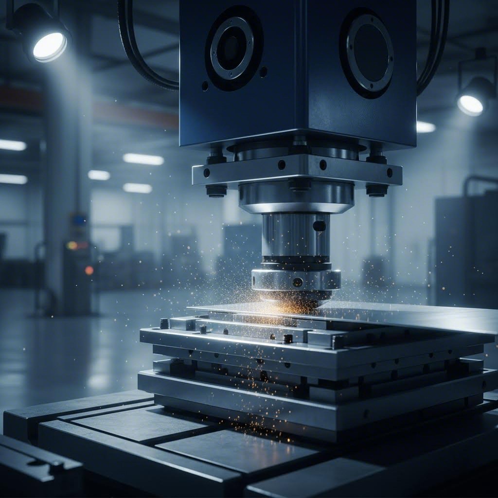
तो, सबसे मूलभूत स्तर पर स्टैम्पिंग ऑपरेशन क्या है? कल्पना कीजिए कि आप धातु की एक समतल शीट को दो सटीक रूप से डिज़ाइन किए गए औज़ारों के बीच रखते हैं: एक पंच (ऊपरी घटक) और एक डाई (निचला घटक)। जब प्रेस सक्रिय होता है, तो वह पंच को विशाल बल के साथ नीचे की ओर धकेलता है—जो अक्सर टन में मापा जाता है—जिससे धातु प्लास्टिक रूप से विकृत हो जाती है और औज़ारों द्वारा परिभाषित आकृति ग्रहण कर लेती है।
इसकी यांत्रिकी में तीन आवश्यक तत्वों का सामंजस्यपूर्ण कार्य शामिल है:
- बल का आरोपण: स्टैम्पिंग प्रेस नियंत्रित दबाव उत्पन्न करता है, जो छोटे भागों के लिए कुछ टन से लेकर ऑटोमोटिव बॉडी पैनल्स के लिए हज़ारों टन तक हो सकता है।
- टूलिंग की सटीकता: डाइज़ और पंचों को सटीक विनिर्देशों के अनुसार मशीन किया जाता है, जिनमें स्पष्टता (क्लीयरेंस) हज़ारवें इंच के माप में मापी जाती है, ताकि भागों की सुसंगत गुणवत्ता सुनिश्चित की जा सके।
- सामग्री प्रवाह: जब दबाव लगाया जाता है, तो धातु प्लास्टिक विरूपण के अधीन हो जाती है, जिससे उसका आकार स्थायी रूप से बदल जाता है, लेकिन उसके संरचनात्मक गुण अपरिवर्तित रहते हैं।
यह प्रक्रिया इसलिए कार्य करती है क्योंकि धातुएँ तन्यता (डक्टिलिटी) प्रदर्शित करती हैं—अर्थात् दरार डाले बिना विरूपित होने की क्षमता। जब लगाया गया बल धातु की यील्ड स्ट्रेंथ (तन्यता सीमा) से अधिक होता है, लेकिन उसके टूटने के बिंदु से कम रहता है, तो यह सामग्री नए आकारों में प्रवाहित हो जाती है और दबाव हटाए जाने के बाद भी उन्हें बनाए रखती है। नेशनल मटेरियल कंपनी के अनुसार, इस दृष्टिकोण से छोटे और बड़े दोनों प्रकार के उत्पादन चक्रों के लिए कम लागत और त्वरित नेतृत्व समय (लीड टाइम) प्राप्त होते हैं, जबकि स्थिर गुणवत्ता और आयामी शुद्धता बनी रहती है।
समतल शीट से परिशुद्ध घटक
व्यावहारिक शब्दों में स्टैम्प्ड धातु क्या है? यह कोई भी घटक है जो एक समतल शीट या कॉइल से शुरू हुआ और धातु प्रेसिंग संचालन के माध्यम से एक कार्यात्मक भाग में परिवर्तित हो गया। स्टैम्पिंग का अर्थ है विशिष्ट ज्यामितीय परिवर्तन प्राप्त करने के लिए विशेषीकृत टूलिंग के माध्यम से रणनीतिक बल का प्रयोग करना—चाहे वह किसी सटीक आउटलाइन को काटना हो, निश्चित कोणों पर मोड़ बनाना हो, या जटिल त्रि-आयामी आकृतियाँ निर्मित करना हो।
कच्चे माल से तैयार घटक तक की यात्रा आमतौर पर इस क्रम का अनुसरण करती है:
- डिजाइन और इंजीनियरिंग: इंजीनियर CAD/CAM सॉफ़्टवेयर का उपयोग करके भाग की ज्यामिति को परिभाषित करते हैं, जिसमें धातु के गुणों, डाई के डिज़ाइन और टूलिंग की आवश्यकताओं पर विचार किया जाता है।
- टूलिंग निर्माण: विशेषीकृत डाइज़ का निर्माण किया जाता है, जिनमें ब्लैंकिंग डाइज़, फॉर्मिंग डाइज़ और पियर्सिंग डाइज़ शामिल हैं।
- सामग्री तैयारी: धातु की शीटें या कॉइल्स को उचित आयामों में काटा, स्लिट किया और समतल किया जाता है।
- स्टैम्पिंग ऑपरेशन: प्रेस डाइज़ के माध्यम से बल लगाती है और कटिंग, बेंडिंग या फॉर्मिंग संचालन करती है।
- पूर्णता: डीबरिंग, सफाई और सतह उपचार जैसे उत्तर-प्रसंस्करण चरण भाग को पूर्ण करते हैं।
इस लेख के पूरे दौरान, आप नौ आवश्यक स्टैम्पिंग ऑपरेशनों की खोज करेंगे, प्रोग्रेसिव डाई बनाम ट्रांसफर डाई विधियों की तुलना करेंगे, सही प्रेस प्रकार और सामग्रियों का चयन कैसे करना है यह सीखेंगे, और उन गुणवत्ता नियंत्रण रणनीतियों को समझेंगे जो सटीक परिणाम सुनिश्चित करती हैं। चाहे आप किसी नए प्रोजेक्ट के लिए स्टैम्पिंग का मूल्यांकन कर रहे हों या अपने तकनीकी ज्ञान को गहरा रहे हों, यह मार्गदर्शिका आधारभूत अवधारणाओं को उन व्यावहारिक विस्तारों से जोड़ती है जो सूचित निर्णय लेने के लिए आवश्यक हैं।
नौ आवश्यक स्टैम्पिंग ऑपरेशन और उनके अनुप्रयोग
अब जब आप स्टैम्पिंग प्रक्रिया के मूल सिद्धांतों को समझ चुके हैं, तो आइए उन विशिष्ट ऑपरेशनों का अध्ययन करें जो समतल धातु को कार्यात्मक घटकों में परिवर्तित करते हैं । प्रत्येक डाई स्टैम्पिंग ऑपरेशन का एक विशिष्ट उद्देश्य होता है, और प्रत्येक तकनीक को कब लागू करना है, यह जानना परिणामों को अनुकूलतम बनाने के लिए अत्यंत महत्वपूर्ण है। इन नौ ऑपरेशनों को अपने उत्पादन उपकरण-किट के रूप में सोचें—प्रत्येक को विशिष्ट कार्यों के लिए डिज़ाइन किया गया है, फिर भी जटिल अंतिम भागों के निर्माण के लिए अक्सर एक साथ संयोजित किया जाता है।
कटिंग संचालन की व्याख्या
कटिंग ऑपरेशन अधिकांश स्टैम्पिंग और प्रेसिंग क्रमों की नींव बनाते हैं। ये तकनीकें सामग्री को अलग करती हैं या खुले स्थान बनाती हैं, जिससे उसके बाद के फॉर्मिंग ऑपरेशनों के लिए मार्ग प्रशस्त हो जाता है।
खाली करना यह शीट धातु से समतल आकृतियों को काटने की प्रक्रिया है, जिसमें पंच किए गए टुकड़े को अंतिम उत्पाद के रूप में प्राप्त किया जाता है। जब आप धातु का ब्लैंक स्टैम्पिंग कर रहे होते हैं, तो सटीकता सर्वाधिक महत्वपूर्ण होती है—डाई को न्यूनतम बर्र निर्माण के साथ साफ किनारों का उत्पादन करना चाहिए। अनुसार, मास्टर प्रोडक्ट्स , ब्लैंकिंग पंचिंग के बहुत समान है, सिवाय इसके कि पंच किए गए भाग ही उत्पाद होते हैं और शेष शीट धातु का कार्य-टुकड़ा कचरा होता है। इसके विशिष्ट अनुप्रयोगों में इलेक्ट्रॉनिक्स के लिए आधार घटकों, ऑटोमोटिव ब्रैकेट्स और उपकरण पैनलों का उत्पादन शामिल है। उपकरणों के लिए कठोर इस्पात डाई की आवश्यकता होती है, जिनमें सटीक खाली स्थान (क्लियरेंस) होते हैं—आमतौर पर सामग्री की मोटाई का 5–10%—ताकि साफ कट बनाए जा सकें।
पंचिंग (पियर्सिंग) यह शीट मेटल के कार्य-टुकड़े के भीतर सटीक स्थान पर छेद बनाता है। ब्लैंकिंग के विपरीत, निकाले गए सामग्री को कचरा माना जाता है, और छिद्रित शीट उत्पादन की प्रक्रिया में आगे बढ़ती रहती है। यह कार्य माउंटिंग होल, वेंटिलेशन खुलासों और कनेक्शन बिंदुओं के निर्माण के लिए आवश्यक है। टूलिंग की जटिलता छेदों के पैटर्न के आधार पर भिन्न होती है—सरल एकल-पंच डाई मूलभूत अनुप्रयोगों को संभालती है, जबकि बहु-स्टेशन सेटअप एकल प्रेस स्ट्रोक में जटिल छेद व्यवस्था बनाते हैं।
आकृति निर्माण एवं आकार प्रदान करने की तकनीकें
एक बार जब कटिंग कार्यों द्वारा मूल आउटलाइन स्थापित कर ली जाती है, तो फॉर्मिंग तकनीकें धातु को त्रि-आयामी घटकों में पुनः आकार देती हैं। इन कार्यों को करते समय सामग्री के गुणों और स्प्रिंगबैक विशेषताओं पर ध्यान देने की आवश्यकता होती है।
मोड़ना यह एक विशिष्ट अक्ष के अनुदिश कोणीय विकृति उत्पन्न करने के लिए यांत्रिक बल का उपयोग करता है। प्रेस ब्रेक अत्यधिक दबाव लगाता है, जिससे आमतौर पर ब्रैकेट्स, एनक्लोज़र्स और संरचनात्मक फ्रेम्स में पाए जाने वाले V-आकार या U-आकार के प्रोफाइल बनते हैं। टूलिंग में मैच किए गए पंच और डाई सेट शामिल हैं, जो विशिष्ट बेंड कोणों के लिए डिज़ाइन किए गए हैं, तथा आंतरिक बेंड त्रिज्या आमतौर पर धातु की तन्यता के आधार पर सामग्री की मोटाई के 0.5 से 2 गुना के बीच होती है।
सिक्का बनाना यह एक उच्च-दबाव वाली क्रिया को दर्शाता है जो कार्य-टुकड़े के दोनों ओर एक साथ स्टैम्पिंग करती है। यह तकनीक उत्कृष्ट सतह के विवरण, सटीक मोटाई नियंत्रण और अन्य विधियों द्वारा प्राप्त न किए जा सकने वाली तीव्र परिभाषा उत्पन्न करती है। कॉइनिंग का उपयोग करके स्टैम्पिंग का एक क्लासिक उदाहरण मुद्रा निर्माण है—अतः इसका नाम ‘कॉइनिंग’ पड़ा है। स्टील और अन्य धातुओं के लिए कॉइनिंग में दबाव पारंपरिक आकृति निर्माण में उपयोग किए जाने वाले दबाव के 5–6 गुना तक पहुँच सकता है, जिसके लिए मज़बूत डाई निर्माण और सटीक संरेखण की आवश्यकता होती है। इसके अनुप्रयोग सजावटी हार्डवेयर, सटीक घटकों और किसी भी ऐसे भाग तक विस्तारित हैं जिनमें ठीक आयामी नियंत्रण की आवश्यकता होती है।
इम्बॉसिंग कार्य-टुकड़े की एक ओर पर मुहर लगाकर उभरे हुए या धंसे हुए पैटर्न बनाता है। जबकि स्टैम्प और एम्बॉसर्स कोइनिंग उपकरणों के समान होते हैं, एम्बॉसिंग के लिए कम दबाव की आवश्यकता होती है क्योंकि यह सामग्री को संपीड़ित करने के बजाय विस्थापित करता है। सामान्य एम्बॉस्ड विशेषताओं में लोगो, श्रृंखला संख्याएँ, सजावटी पैटर्न और ब्रांडिंग तत्व शामिल हैं। टूलिंग में मैच किए गए पुरुष और मादा डाई होते हैं जिनमें नियंत्रित क्लियरेंस होते हैं जो पैटर्न की गहराई निर्धारित करते हैं।
फ्लैंजिंग किनारों को शीट की सतह से 90-डिग्री के कोण पर मोड़ता है, आमतौर पर पंच किए गए छेदों के चारों ओर या भाग की परिधि के अनुदिश। यह कार्य सुचारू किनारों का निर्माण करता है जो तीव्र किनारों को समाप्त करते हैं, संरचनात्मक दृढ़ता में सुधार करते हैं और असेंबली को सुविधाजनक बनाते हैं। फ्लैंजिंग टैंक, पाइप और ऑटोमोटिव बॉडी पैनल के निर्माण में आवश्यक है, जहाँ किनारे की गुणवत्ता सुरक्षा और सौंदर्य दोनों को प्रभावित करती है।
खिंचाव यह संचालन किनारों को क्लैम्प रखते हुए सामग्री को डाई कैविटी में धकेलकर उभार या आकृतियाँ बनाता है। इस संचालन द्वारा ऑटोमोबाइल के दरवाज़े के पैनल और छत के अनुभाग जैसे जटिल आकार उत्पन्न किए जाते हैं, जहाँ सामग्री को वक्र सतहों पर प्रवाहित होना आवश्यक होता है। सामग्री के प्रवाह को नियंत्रित करने और झुर्रियों को रोकने के लिए टूलिंग में ड्रॉ बीड्स या ब्लैंक होल्डर्स की आवश्यकता होती है।
मोड़ना यह संचालन शीट धातु के किनारों को बेलनाकार आकृतियों में लोलिंग करता है, जिससे कब्ज़ों, तार गाइड्स और सुरक्षा किनारों के लिए गोलाकार प्रोफाइल बनते हैं। आवेदन की आवश्यकताओं के आधार पर यह संचालन पूर्ण ट्यूब या आंशिक रोल दोनों बना सकता है। टूलिंग में विशेष रूप से आकृति वाली डाइज़ शामिल होती हैं, जो कई फॉर्मिंग चरणों के माध्यम से सामग्री को क्रमिक रूप से आकार देती हैं।
ग्रोइंग यह संचालन धातु की शीट में चैनल या खांचे काटता है, बिना सामग्री को पूर्णतः भेदे बिना। ये विशेषताएँ मोड़ की रेखाओं के रूप में कार्य करती हैं, ओ-रिंग्स के लिए स्थान प्रदान करती हैं, या सजावटी तत्व बनाती हैं। खांचा बनाने की टूलिंग में सुसंगत खांचा प्रोफाइल प्राप्त करने के लिए सटीक गहराई नियंत्रण की आवश्यकता होती है, बिना सामग्री के अलग होने के।
| संचालन का नाम | विवरण | विशिष्ट अनुप्रयोग | औजार की जटिलता |
|---|---|---|---|
| खाली करना | शीट से समतल आकृतियों को काटना; पंच किया गया टुकड़ा उत्पाद होता है | बेस घटक, ब्रैकेट्स, उपकरण पैनल | मध्यम—साफ किनारों के लिए सटीक क्लीयरेंस की आवश्यकता होती है |
| पंच करना | छेद या कटआउट बनाना; पंच किया गया सामग्री कचरा होती है | माउंटिंग छेद, वेंटिलेशन, कनेक्शन बिंदु | कम से मध्यम—छेद पैटर्न के साथ जटिलता बढ़ जाती है |
| मोड़ना | एक विशिष्ट अक्ष के अनुदिश कोणीय विरूपण | ब्रैकेट्स, एनक्लोजर्स, संरचनात्मक फ्रेम | मध्यम—विशिष्ट कोणों के लिए मैच किए गए पंच/डाई सेट |
| सिक्का बनाना | उच्च-दबाव स्टैम्पिंग दोनों ओर से सूक्ष्म विवरण के लिए | मुद्रा, सजावटी हार्डवेयर, परिशुद्धि घटक | उच्च—अत्यधिक दाब के लिए मजबूत निर्माण की आवश्यकता होती है |
| इम्बॉसिंग | एक तरफ उभरे हुए/धंसे हुए पैटर्न बनाना | लोगो, श्रृंखला संख्याएँ, सजावटी तत्व | मध्यम—पैटर्न की गहराई के लिए नियंत्रित स्पष्टता |
| फ्लैंजिंग | शीट की सतह से 90° पर किनारों को मोड़ना | टैंक, पाइप, ऑटोमोटिव पैनल | मध्यम—विशिष्ट किनारा-आकार देने वाले औजार |
| खिंचाव | किनारों को क्लैम्प रखते हुए कंटूर बनाना | ऑटोमोटिव दरवाज़े, छत के पैनल, उपकरण के कवर | उच्च—ड्रॉ बीड्स और सामग्री प्रवाह नियंत्रण की आवश्यकता होती है |
| मोड़ना | किनारों को बेलनाकार आकृतियों में मोड़ना | कब्जे, तार गाइड, सुरक्षा किनारे | मध्यम से उच्च—प्रगतिशील आकृति निर्माण चरण |
| ग्रोइंग | पूर्ण प्रवेश के बिना छेदन चैनलों का निर्माण | मोड़ रेखाएँ, O-रिंग सीटें, सजावटी विशेषताएँ | मध्यम—सटीक गहराई नियंत्रण की आवश्यकता |
इन नौ संचालनों को समझना आपको अपनी विशिष्ट ब्लैंक स्टैम्पिंग आवश्यकताओं के लिए सही तकनीकों का चयन करने में सक्षम बनाता है। कई उत्पादन परिदृश्यों में एकाधिक संचालनों का संयोजन किया जाता है—शायद ब्लैंकिंग के बाद मोड़ना और फ्लैंजिंग —जिससे अंतिम घटकों का कुशलतापूर्ण निर्माण किया जा सके। मुख्य बात यह है कि संचालन की क्षमताओं को भाग की ज्यामिति, उत्पादन मात्रा और गुणवत्ता आवश्यकताओं के साथ सुसंगत किया जाए। इस आधार के साथ, आप तैयार हैं कि ये संचालन कैसे प्रगतिशील, ट्रांसफर और फोरस्लाइड स्टैम्पिंग प्रणालियों में व्यवस्थित किए जाते हैं, इसका अध्ययन करें।
प्रगतिशील बनाम ट्रांसफर बनाम फोरस्लाइड स्टैम्पिंग विधियाँ
आपने नौ आवश्यक स्टैम्पिंग कार्यों पर महारत हासिल कर ली है—लेकिन इन्हें एक कुशल उत्पादन प्रणाली में कैसे व्यवस्थित किया जाए? इसका उत्तर आपकी विशिष्ट आवश्यकताओं के अनुसार सही स्टैम्पिंग प्रौद्योगिकी का चयन करने पर निर्भर करता है। आधुनिक स्टैम्पिंग मशीनरी में तीन प्राथमिक विधियाँ प्रभुत्व स्थापित करती हैं: प्रोग्रेसिव डाई, ट्रांसफर डाई और फोरस्लाइड स्टैम्पिंग। प्रत्येक विधि के अपने विशिष्ट लाभ हैं, और गलत विधि का चयन करना लाभदायक उत्पादन स्टैम्पिंग और महंगी अक्षमता के बीच का अंतर निर्धारित कर सकता है।
उच्च मात्रा वाले उत्पादन के लिए प्रोग्रेसिव डाई के लाभ
कल्पना कीजिए कि एक निरंतर धातु की पट्टी एक श्रृंखला के स्टेशनों के माध्यम से आगे बढ़ रही है, जिनमें से प्रत्येक एक विशिष्ट कार्य—पंचिंग, बेंडिंग, फॉर्मिंग—करता है, जब तक कि अंत में पूर्ण स्टैम्पिंग वाले भाग नहीं निकल आते। यह है प्रोग्रेसिव डाई और स्टैम्पिंग का कार्यान्वयन । प्रत्येक प्रेस स्ट्रोक के साथ पट्टी डाई के माध्यम से क्रमिक रूप से आगे बढ़ती है, और भाग अंतिम कट-ऑफ कार्य द्वारा उन्हें अलग करने तक कैरियर पट्टी (जिसे वेबिंग कहा जाता है) से जुड़े रहते हैं।
इस दृष्टिकोण का उच्च-मात्रा वाले उत्पादन में प्रभुत्व क्यों है? इन प्रमुख लाभों पर विचार करें:
- अद्वितीय गति: प्रगतिशील डाई (डाई) के साथ काम करने वाली स्टैम्पिंग मशीनें प्रति मिनट सैकड़ों भागों का उत्पादन कर सकती हैं, क्योंकि सभी संचालन एक साथ कई स्टेशनों पर होते हैं।
- कम हैंडलिंग: भाग पूर्ण होने तक स्ट्रिप से कभी नहीं निकलते, जिससे स्थानांतरण तंत्र समाप्त हो जाते हैं और श्रम लागत में कमी आती है।
- प्रति इकाई कम लागत: एक बार टूलिंग स्थापित हो जाने के बाद, प्रक्रिया की निरंतर प्रकृति के कारण बड़े पैमाने पर प्रति-टुकड़ा लागत में तेज़ी से कमी आती है।
- स्थिर गुणवत्ता: स्ट्रिप पूरे समय दौरान सटीक स्थिति बनाए रखती है, जिससे लाखों चक्रों के दौरान आकारिक दोहरावीयता सुनिश्चित होती है।
प्रगतिशील स्टैम्पिंग सरल से मध्यम जटिलता वाले भागों के लिए उत्कृष्ट है—जैसे कि ऑटोमोटिव ब्रैकेट्स, विद्युत कनेक्टर्स, बैटरी संपर्क बिंदु, और सटीक हार्डवेयर। डाई-मैटिक के अनुसार, यह विधि उत्पादन की गति, त्वरित साइकिल समय, कम श्रम लागत और प्रति-इकाई कम लागत प्रदान करती है, जिससे यह सटीक भागों के बड़े मात्रा में त्वरित और लागत-प्रभावी उत्पादन के लिए सबसे प्रभावी विधियों में से एक बन जाती है।
हालांकि, प्रगतिशील डाईज़ (डाईज़) के साथ कुछ समझौते भी जुड़े होते हैं। प्रारंभिक टूलिंग निवेश काफी महंगा हो सकता है—बहु-स्टेशन वाली जटिल डाईज़ के लिए व्यापक इंजीनियरिंग और उच्च-सटीकता वाले निर्माण की आवश्यकता होती है। टूलिंग पूर्ण होने के बाद डिज़ाइन में संशोधन करना महंगा और समय-साध्य हो जाता है। इसके अतिरिक्त, भाग की ज्यामिति लगातार फीड होने वाले स्ट्रिप की सीमाओं द्वारा प्रभावित होती है: बहुत गहरे ड्रॉ या बड़े घटक ऐसे हो सकते हैं जिन्हें प्रगतिशील स्टैम्पिंग मशीनरी द्वारा संभाला जाना संभव न हो।
जब ट्रांसफर डाई प्रगतिशील प्रणालियों से श्रेष्ठ प्रदर्शन करती हैं
जब आपके भाग को गहरे ड्रॉ, बड़े आयाम या ऐसी ज्यामितीय जटिलता की आवश्यकता होती है जिसे प्रगतिशील डाईज़ संभाल नहीं सकतीं, तो क्या होता है? ट्रांसफर डाई स्टैम्पिंग इसका समाधान प्रदान करती है। इस विधि में या तो पूर्व-कट ब्लैंक के साथ प्रक्रिया शुरू की जाती है या प्रक्रिया के आरंभ में ही कार्य-टुकड़े को स्ट्रिप से अलग कर दिया जाता है। इसके बाद यांत्रिक उंगलियाँ या ट्रांसफर तंत्र व्यक्तिगत भाग को पृथक डाई स्टेशनों के बीच स्थानांतरित करते हैं।
ट्रांसफर स्टैम्पिंग उन परिस्थितियों में उत्कृष्ट प्रदर्शन करती है जहाँ प्रगतिशील विधियाँ असफल हो जाती हैं:
- बड़े भाग: ऑटोमोटिव बॉडी पैनल, संरचनात्मक घटक और भारी ड्यूटी एनक्लोज़र्स को ट्रांसफर डाई की लचीलापन से लाभ होता है।
- जटिल ज्यामितियाँ: जब भागों को कई कोणों से या गहरे फॉर्मिंग के साथ संचालन की आवश्यकता होती है, जो स्ट्रिप फीड को अवरुद्ध कर सकता है, तो ट्रांसफर डाइज़ एक्सेस प्रदान करते हैं।
- सामग्री दक्षता: अनुकूलित ब्लैंक्स के साथ शुरू करने से कुछ भाग आकृतियों के लिए निरंतर स्ट्रिप फीडिंग की तुलना में कचरा कम किया जा सकता है।
सौदे का दूसरा पक्ष? ट्रांसफर स्टैम्पिंग आमतौर पर प्रोग्रेसिव विधियों की तुलना में धीमी गति से चलती है, क्योंकि भागों को स्टेशनों के बीच भौतिक रूप से स्थानांतरित किया जाना चाहिए। उपकरण और हैंडलिंग की जटिलता कम मात्रा वाले उत्पादन के लिए लागत में वृद्धि करती है। फिर भी, जटिल या अत्यधिक आकार के स्टैम्प्ड भागों के मध्यम से उच्च मात्रा वाले उत्पादन के लिए, ट्रांसफर डाई प्रणालियाँ अतुलनीय क्षमता प्रदान करती हैं।
फोरस्लाइड स्टैम्पिंग एक पूरी तरह से अलग दृष्टिकोण अपनाता है। ऊर्ध्वाधर दबाव क्रिया के बजाय, फोरस्लाइड (या मल्टीस्लाइड) स्टैम्पिंग मशीनें चार या अधिक क्षैतिज उपकरण स्लाइड्स का उपयोग करती हैं, जो धातु को एक साथ कई दिशाओं से आकार देती हैं। यह बहु-अक्षीय आकृति निर्माण क्षमता जटिल मोड़ों, मुड़ावों और त्रि-आयामी आकृतियों के निर्माण में उत्कृष्टता प्रदर्शित करती है, जिन्हें पारंपरिक स्टैम्पिंग मशीनरी में कई ऑपरेशनों की आवश्यकता होती है।
फोरस्लाइड प्रौद्योगिकि निम्नलिखित के लिए आदर्श सिद्ध होती है:
- जटिल छोटे भाग: विद्युत कनेक्टर्स, टर्मिनल्स, क्लिप्स और फास्टनर्स जिनमें सटीक बहु-दिशात्मक मोड़ होते हैं।
- वायर फॉर्म्स और फ्लैट स्प्रिंग्स: उन घटकों के लिए जिन्हें पतली, लचीली सामग्रियों से जटिल ज्यामितियों की आवश्यकता होती है।
- द्वितीयक ऑपरेशनों में कमी: ऐसे भाग जिन्हें अन्यथा कई आकृति निर्माण चरणों की आवश्यकता होती है, अक्सर एकल फोरस्लाइड चक्र में पूरे किए जा सकते हैं।
सीमाएँ क्या हैं? फोरस्लाइड स्टैम्पिंग आमतौर पर छोटे भागों और पतली सामग्री के लिए उपयुक्त होती है। यह भारी-गेज धातुओं या बड़े घटकों के लिए कम प्रभावी है, और उत्पादन मात्रा आमतौर पर प्रोग्रेसिव डाई ऑपरेशन्स की तुलना में कम होती है।
| मानदंड | प्रोग्रेसिव डाई stamping | ट्रांसफर डाइ स्टैम्पिंग | फोरस्लाइड स्टैम्पिंग |
|---|---|---|---|
| खंड जटिलता | सरल से मध्यम; स्ट्रिप फीड द्वारा सीमित | उच्च; गहरी ड्रॉ और जटिल आकारों के लिए उपयुक्त | बहुत उच्च; जटिल बेंड्स के लिए बहु-दिशात्मक फॉर्मिंग |
| उत्पादन मात्रा | मध्यम से बहुत उच्च; बड़े पैमाने पर उत्पादन के लिए आदर्श | मध्यम से उच्च; बड़े बैच रन के लिए कुशल | निम्न से मध्यम; विशिष्ट घटकों के लिए उपयुक्त |
| टूलिंग लागत | प्रारंभिक निवेश उच्च; लेकिन उच्च मात्रा में प्रति भाग लागत कम | स्थानांतरण तंत्र और बहु-स्टेशन के कारण उच्च | मध्यम; प्रगतिशील डाई की तुलना में कम जटिल |
| समय चक्र | सबसे तेज़; सभी संचालन एक साथ किए जाते हैं | धीमी; स्टेशनों के बीच भाग का स्थानांतरण | मध्यम; आकार देने की जटिलता पर निर्भर |
| सर्वश्रेष्ठ उपयोग | ऑटोमोटिव ब्रैकेट, कनेक्टर, विद्युत टर्मिनल, सटीक हार्डवेयर | बड़े बॉडी पैनल, संरचनात्मक घटक, गहराई से खींचे गए भाग | छोटे कनेक्टर, क्लिप, स्प्रिंग, वायर फॉर्म |
आप सही विधि का चयन कैसे करते हैं? इन निर्णय आधारों का मूल्यांकन करके शुरुआत करें:
- भाग का आकार और ज्यामिति: मध्यम जटिलता वाले छोटे, सपाट भागों को प्रगतिशील मरने की वकालत करते हैं। बड़े या गहरे भागों को स्थानांतरण प्रणाली की ओर इशारा करते हैं। जटिल बहु-बेंड छोटे भागों चौकों की ओर संकेत करते हैं।
- उत्पादन मात्रा: उच्च मात्रा में चलने से प्रगतिशील मर उपकरण निवेश उचित है। कम मात्रा में चौतरफा स्लाइड लचीलापन या स्थानांतरण मरने बहुमुखी प्रतिभा को बढ़ावा दे सकता है।
- द्रव्य का गाढ़ापन: पतली, लचीली धातुएं सभी तरीकों से अच्छी तरह काम करती हैं। भारी गेज चौतरफा स्लाइड क्षमता से अधिक हो सकते हैं।
- बजट की सीमा: उपकरण की कटौती, प्रति भाग लागत और द्वितीयक संचालन आवश्यकताओं सहित कुल लागत पर विचार करें।
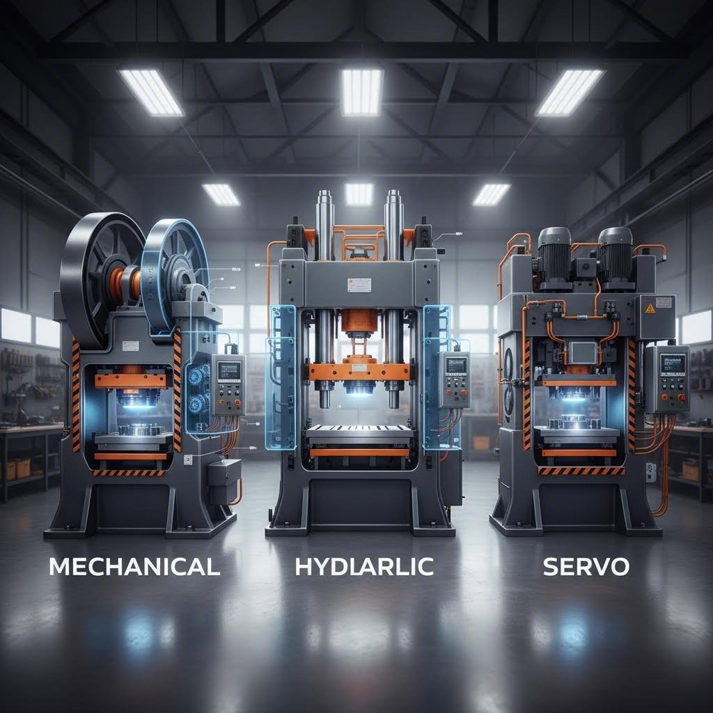
अपनी मुहर लगाने की विधि का चयन करने के बाद, अगला महत्वपूर्ण निर्णय सही प्रेस प्रकार का चयन करना है। यांत्रिक, हाइड्रोलिक और सर्वो प्रेस में से प्रत्येक विशिष्ट विशेषताएं हैं जो आपके उत्पादन दक्षता को बढ़ा या तोड़ सकती हैं।
स्टैम्पिंग प्रेस के प्रकार और चयन मापदंड
आपने अपनी स्टैम्पिंग विधि का चयन कर लिया है—लेकिन आपके उत्पादन को कौन-सी मशीन संचालित करेगी? जिस स्टैम्पिंग प्रेस का आप चयन करते हैं, वह साइकिल की गति, भाग की गुणवत्ता, ऊर्जा खपत और दीर्घकालिक संचालन लागत को सीधे प्रभावित करती है। तो, स्टैम्पिंग प्रेस क्या है? यह किसी भी स्टैम्पिंग संचालन का यांत्रिक हृदय है: एक मशीन जो उपकरणों के माध्यम से नियंत्रित बल लगाकर धातु को अंतिम घटकों में आकार देती है। यांत्रिक, हाइड्रोलिक और सर्वो प्रेस के बीच के अंतरों को समझना आपको अपनी विशिष्ट विनिर्माण आवश्यकताओं के अनुरूप उपकरण क्षमताओं का चयन करने में सक्षम बनाता है।
यांत्रिक प्रेस की गति और परिशुद्धता के बीच समझौते
यांत्रिक स्टैम्पिंग प्रेस को अक्सर उद्योग के कार्यशील घोड़ों के रूप में संबोधित किया जाता है—और इसका अच्छा कारण भी है। ये धातु स्टैम्पिंग प्रेस घूर्णन ऊर्जा को संग्रहीत करने और उसे रैखिक बल में परिवर्तित करने के लिए फ्लाईव्हील-एंड-क्रैंकशाफ्ट तंत्र पर निर्भर करती हैं। जब क्लच सक्रिय होता है, तो उस संग्रहीत ऊर्जा के कारण रैम अद्भुत गति और स्थिरता के साथ नीचे की ओर गति करता है।
यह कैसे काम करता है: एक विद्युत मोटर लगातार एक भारी फ्लाईव्हील को घुमाती रहती है, जिससे गतिज ऊर्जा का निर्माण होता है। प्रेस स्ट्रोक के दौरान, यह ऊर्जा क्रैंकशाफ्ट के माध्यम से रैम तक स्थानांतरित होती है, जो स्ट्रोक के अंत में बल प्रदान करती है। निश्चित स्ट्रोक लंबाई और भविष्यवाणि योग्य गति प्रोफ़ाइल के कारण यांत्रिक प्रेस को उन प्रक्रियाओं के लिए आदर्श माना जाता है जिनमें गति और दोहराव की आवश्यकता होती है।
जेवीएम निर्माण के अनुसार, यांत्रिक स्टैम्पिंग प्रेस अपनी गति के लिए प्रसिद्ध हैं और प्रति मिनट उच्च स्ट्रोक प्राप्त कर सकते हैं, जिससे वे उन बड़े पैमाने पर उत्पादन चलाने के लिए आदर्श हो जाते हैं जहाँ समय सीधे लाभप्रदता को प्रभावित करता है।
फायदे
- उच्च-गति संचालन: छोटे प्रेस के लिए चक्र दर 1,000 स्ट्रोक प्रति मिनट से अधिक हो सकती है, जिससे उत्पादन क्षमता अधिकतम हो जाती है।
- कम प्रारंभिक लागत: हाइड्रोलिक या सर्वो विकल्पों की तुलना में सरल निर्माण प्रारंभिक निवेश को कम करता है।
- साबित हुई विश्वसनीयता: सीधी-सादी डिज़ाइन का अर्थ है कम रखरखाव और समस्या निवारण करने में आसानी।
- गति पर ऊर्जा दक्षता: लगातार संचालन के दौरान स्ट्रोक के बीच फ्लाईव्हील का संवेग ऊर्जा को पुनर्प्राप्त करता है।
नुकसान
- निश्चित स्ट्रोक विशेषताएँ: नीचे के मृत बिंदु पर विभिन्न आकार-निर्माण गहराई या रुकावट के समय के लिए सीमित लचीलापन।
- कम नियंत्रण: स्ट्रोक के निचले भाग पर बल का शिखर बनता है, जबकि पूरी अवधि में स्थिर नहीं रहता है।
- गहरी ड्रॉइंग क्षमता सीमित है: विस्तारित आकार-निर्माण दूरियों के दौरान लगातार दबाव की आवश्यकता वाले कार्यों के लिए यह आदर्श नहीं है।
यांत्रिक प्रकार का एक स्टील स्टैम्पिंग प्रेस उच्च-गति ब्लैंकिंग, उथले आकार-निर्माण और उन दोहराव वाले कार्यों में उत्कृष्ट प्रदर्शन करता है, जहाँ स्थिर साइकिल समय लचीलापन की आवश्यकता से अधिक महत्वपूर्ण होता है। उदाहरण के लिए, विद्युत टर्मिनल, छोटे ब्रैकेट और सटीक हार्डवेयर, जो वार्षिक रूप से लाखों इकाइयों में उत्पादित किए जाते हैं।
हाइड्रॉलिक धातु स्टैम्पिंग प्रेस के बारे में क्या कहा जाए? ये मशीनें मौलिक रूप से भिन्न दृष्टिकोण अपनाती हैं। यांत्रिक ऊर्जा भंडारण के बजाय, हाइड्रॉलिक प्रेस पंप और सिलेंडर द्वारा उत्पन्न द्रव दबाव का उपयोग बल लगाने के लिए करती हैं। यह डिज़ाइन पूरे स्ट्रोक के दौरान परिवर्तनशील बल लगाने की क्षमता प्रदान करती है—जो गहरी ड्रॉइंग और जटिल आकार-निर्माण कार्यों के लिए एक महत्वपूर्ण लाभ है।
हाइड्रोलिक लाभ तब स्पष्ट हो जाता है जब बड़े ऑटोमोटिव पैनल या गहरे कंटेनरों का निर्माण किया जाता है। धातु स्टैम्पिंग प्रेस मशीन डाई के कैविटी में सामग्री के प्रवाह के दौरान स्थिर दबाव बनाए रखती है, जिससे पतला होने और फटने जैसी समस्याओं को रोका जाता है, जो यांत्रिक प्रेस के निश्चित बल वक्रों के कारण हो सकती हैं। समायोज्य स्ट्रोक लंबाई और कार्यक्रमणीय दबाव प्रोफाइल विविधता प्रदान करते हैं, जिसकी यांत्रिक प्रणालियाँ नकल नहीं कर सकतीं।
फायदे
- पूर्ण-स्ट्रोक बल नियंत्रण: स्ट्रोक के शीर्ष से नीचे तक स्थिर दबाव आवेदन सामग्री के एकसमान प्रवाह को सुनिश्चित करता है।
- गहरी ड्रॉइंग में उत्कृष्टता: कंटेनरों, एनक्लोज़र्स और विस्तारित फॉर्मिंग गहराई की आवश्यकता वाले ऑटोमोटिव बॉडी पैनलों के निर्माण के लिए आदर्श।
- व्यवस्थापनीय पैरामीटर्स: स्ट्रोक लंबाई, गति और बल को यांत्रिक परिवर्तनों के बिना संशोधित किया जा सकता है।
- विविध अनुप्रयोग: एक ही प्रेस उपकरण को बदले बिना केवल सेटिंग्स को समायोजित करके विविध प्रक्रियाओं को संभाल सकती है।
नुकसान
- धीमे साइकिल समय: हाइड्रोलिक प्रणालियाँ आमतौर पर प्रति मिनट 10–20 स्ट्रोक की गति से चलती हैं, जबकि यांत्रिक प्रेस की गति सैकड़ों प्रति मिनट हो सकती है।
- उच्च ऊर्जा खपत: निरंतर पंप संचालन निष्क्रिय अवधि के दौरान भी शक्ति का उपभोग करता है।
- मरम्मत की जटिलता: हाइड्रोलिक द्रव, सील्स और पंपों का नियमित रूप से ध्यान रखना और अंततः प्रतिस्थापन करना आवश्यक है।
सर्वो तकनीक: स्टैम्पिंग नियंत्रण को क्रांतिकारी बनाना
सर्वो-चालित स्टैम्पिंग प्रेस धातु आकृति निर्माण तकनीक के अग्रणी क्षेत्र का प्रतिनिधित्व करते हैं। ये उन्नत मशीनें पारंपरिक फ्लाईव्हील या हाइड्रोलिक प्रणालियों को सर्वो मोटर्स के साथ प्रतिस्थापित करती हैं, जो सीधे रैम की गति को नियंत्रित करती हैं। परिणाम? अभूतपूर्व लचीलापन और सटीकता, जो स्टैम्पिंग ऑपरेशनों में संभव के सीमाओं को पुनः परिभाषित कर रही है।
प्रत्येक ऑपरेशन के लिए सटीक गति प्रोफाइल को प्रोग्राम करने की कल्पना करें—दृढ़ता से आगे की ओर त्वरित होना, आकार देने के दौरान सटीक रूप से धीमा होना, कॉइनिंग ऑपरेशन के लिए निचले मृत बिंदु पर ठहरना, और फिर अधिकतम गति से पीछे की ओर लौटना। सर्वो प्रेस इस प्रकार के अनुकूलन को एक दैनिक अभ्यास बना देते हैं, न कि एक असामान्य घटना।
आइगेन इंजीनियरिंग द्वारा उल्लेखित के अनुसार, सर्वो प्रेस उन्नत सर्वो मोटर तकनीक प्रदान करते हैं, जो गति, शक्ति और प्रोग्राम करने की क्षमता को सक्षम बनाती है—यह इलेक्ट्रॉनिक्स, चिकित्सा उत्पादों या उच्च-गुणवत्ता वाले स्टैम्प किए गए धातु भागों जैसे उच्च सटीकता की आवश्यकता वाले कार्यों के लिए बेहद उपयुक्त है।
फायदे
- प्रोग्राम करने योग्य गति प्रोफाइल: प्रत्येक विशिष्ट कार्य के लिए गति, त्वरण और प्रतीक्षा समय को अनुकूलित करें।
- ऊर्जा दक्षता: मोटरें केवल आवश्यकता होने पर ही संचालित होती हैं, जिससे निरंतर चल रहे यांत्रिक प्रेस की तुलना में शक्ति खपत 30–50% तक कम हो जाती है।
- उत्कृष्ट सटीकता: सटीक स्थिति नियंत्रण से छोटी सहिष्णुता (टॉलरेंस) और सुधारित भाग स्थिरता सुनिश्चित होती है।
- त्वरित परिवर्तन: डिजिटल प्रोग्रामिंग से मिश्रित उत्पादन वातावरण के लिए त्वरित सेटअप परिवर्तन संभव होते हैं।
- कम शोर और कंपन: नियंत्रित मंदन धक्के के बलों और कार्यस्थल के शोर को न्यूनतम करता है।
नुकसान
- उच्च प्रारंभिक निवेश: उन्नत सर्वो प्रौद्योगिकी की लागत समकक्ष यांत्रिक प्रेस की तुलना में काफी अधिक होती है।
- तकनीकी विशेषज्ञता की आवश्यकता: प्रोग्रामिंग और रखरखाव के लिए विशिष्ट ज्ञान की आवश्यकता होती है।
- अधिकतम गति सीमाएँ: प्रति मिनट अधिकतम स्ट्रोक्स की संख्या समर्पित उच्च-गति यांत्रिक प्रेसों के अनुरूप नहीं हो सकती है।
ऊष्मा उत्पादन के बारे में क्या कहा जाए? तापीय विचार प्रेस के चयन और संचालन में एक महत्वपूर्ण भूमिका निभाते हैं। उच्च-गति स्टैम्पिंग के दौरान, डाई, पंच और कार्य-टुकड़े के बीच घर्षण से उल्लेखनीय ऊष्मा उत्पन्न होती है। यह तापीय ऊर्जा डाई के जीवनकाल, स्नेहक की प्रभावशीलता और भागों की आयामी शुद्धता को प्रभावित करती है।
अधिकतम गति पर संचालित होने वाले यांत्रिक प्रेस अपने तीव्र चक्रण के कारण सबसे अधिक घर्षण ऊष्मा उत्पन्न करते हैं। उचित शीतलन या स्नेहन के बिना, डाई की सतहें ऐसे तापमान तक पहुँच सकती हैं जो घिसावट को तीव्र कर देते हैं और पूर्वकालिक विफलता का कारण बनते हैं। तापीय प्रसार के कारण आयामी स्थिरता प्रभावित होने से भागों की गुणवत्ता भी कम हो जाती है।
हाइड्रोलिक और सर्वो प्रेस यहां लाभ प्रदान करते हैं। उनकी धीमी कार्यप्रणाली और नियंत्रित आकृति देने की गति घर्षण से उत्पन्न ऊष्मा को कम करती है। सर्वो प्रेस में महत्वपूर्ण आकृति निर्माण क्षेत्रों के माध्यम से धीमी आगमन गति को कार्यक्रमित करने की क्षमता भी शामिल है, जिससे थर्मल बिल्डअप को और अधिक कम किया जा सकता है, बिना कुल चक्र दक्षता को प्रभावित किए।
आप अपने अनुप्रयोग के लिए प्रेस प्रकार को कैसे मिलाते हैं? इन निर्णय कारकों पर विचार करें:
- उत्पादन मात्रा: उच्च-मात्रा वाले, सरल कार्यों के लिए यांत्रिक स्टील प्रेस की गति अधिक उपयुक्त होती है। कम मात्रा वाले उत्पादन के लिए हाइड्रोलिक या सर्वो प्रेस की लचीलापन का लाभ उठाया जा सकता है।
- भाग की जटिलता: गहरी ड्रॉ और जटिल आकृति निर्माण अनुक्रम हाइड्रोलिक या सर्वो क्षमताओं के अनुरूप होते हैं। उथली ब्लैंकिंग के लिए यांत्रिक प्रेस उपयुक्त होते हैं।
- सहिष्णुता आवश्यकताएँ: दृढ़ आयामी विनिर्देशों के लिए सर्वो प्रेस की परिशुद्धता अधिक उपयुक्त होती है।
- ऊर्जा लागत: उच्च विद्युत दरों वाली सुविधाओं के लिए सर्वो प्रेस की ऊर्जा दक्षता, भले ही उपकरण लागत अधिक हो, लाभदायक हो सकती है।
- उत्पादन मिश्रण: विविध भागों के निर्माण करने वाली दुकानों को त्वरित परिवर्तन के लिए सर्वो प्रोग्रामेबिलिटी से लाभ होता है।
प्रेस प्रकार निर्धारित हो जाने के बाद, आपका अगला महत्वपूर्ण निर्णय सामग्री के चयन से संबंधित है। विभिन्न धातुएँ स्टैम्पिंग के दौरान अद्वितीय रूप से व्यवहार करती हैं, और इन विशेषताओं को समझना गुणवत्तापूर्ण परिणामों और डाई के अनुकूल जीवनकाल के लिए आवश्यक है।
स्टैम्प किए गए घटकों के लिए सामग्री चयन गाइड
आपने अपने प्रेस प्रकार का चयन कर लिया है—अब एक ऐसा निर्णय लेना है जो सीधे भाग के प्रदर्शन, टूलिंग की दीर्घायु और विनिर्माण लागत को प्रभावित करता है: स्टैम्पिंग के लिए सही धातु का चयन करना। प्रत्येक सामग्री स्टैम्पिंग संचालनों में शामिल विशाल बलों के अधीन अलग-अलग तरीके से व्यवहार करती है। सावधानीपूर्ण चयन करें, और आपके भाग उत्कृष्ट आयामी शुद्धता और सतह की गुणवत्ता के साथ उभरेंगे। गलत चयन करें, और आप दरारों, अत्यधिक स्प्रिंगबैक या डाई के शीघ्र घिसावट के साथ संघर्ष करेंगे।
स्टैम्पिंग के लिए एक धातु को आदर्श बनाने वाले कौन-कौन से कारक हैं? चार प्रमुख गुण स्टैम्पेबिलिटी को निर्धारित करते हैं:
- लचीलापन: सामग्री का भंगुरता के बिना प्लास्टिक रूप से विकृत होने की क्षमता। उच्च तन्यता अधिक आक्रामक फॉर्मिंग संचालनों की अनुमति देती है।
- प्रदान क्षमता: वह प्रतिबल स्तर जिस पर स्थायी विरूपण शुरू होता है। कम यील्ड स्ट्रेंथ का अर्थ है कि आकार देना आसान होगा, लेकिन अंतिम भाग की शक्ति में कमी आ सकती है।
- कार्य दृढीकरण दर: धातु के विरूपित होने के साथ-साथ यह कितनी तेज़ी से कठोर और कम आकार देने योग्य हो जाती है। उच्च कार्य कठोरीकरण बहु-चरणीय संचालनों में समस्याएँ उत्पन्न कर सकता है।
- अनाज संरचना: सूक्ष्म, समान दाने आमतौर पर मोटे या अनियमित दाने के पैटर्न की तुलना में आकार देने की क्षमता और सतह के फिनिश को बेहतर बनाते हैं।
इन गुणों को समझना आपको ब्लैंकिंग, बेंडिंग, ड्रॉइंग और अन्य स्टैम्पिंग संचालन के दौरान प्रत्येक सामग्री के प्रदर्शन की भविष्यवाणी करने में सहायता करता है। आइए सबसे आम धातु स्टैम्पिंग सामग्रियों और उनकी विशिष्ट विशेषताओं का अध्ययन करें।
इस्पात ग्रेड और उनकी स्टैम्पिंग विशेषताएँ
स्टैम्पिंग उद्योग में स्टील का प्रभुत्व अच्छे कारणों से है—यह शक्ति, आकार देने की क्षमता और लागत-प्रभावशीलता का संयोजन प्रदान करता है, जिसकी कोई भी विकल्प कम नहीं कर सकता। हालाँकि, "स्टील" में दर्जनों ग्रेड शामिल हैं, जिनमें से प्रत्येक का उपयोग विभिन्न अनुप्रयोगों के लिए किया जाता है।
कार्बन स्टील स्टैम्प्ड स्टील उत्पादन के कार्यक्षेत्र में इसका उपयोग प्रमुख रूप से किया जाता है। टैलन उत्पादों के अनुसार, कार्बन स्टील का उपयोग स्टैम्पिंग में व्यापक रूप से किया जाता है क्योंकि यह मजबूत, सस्ती और आकार देने में आसान होती है। कार्बन सामग्री के आधार पर विभिन्न ग्रेड विशिष्ट उद्देश्यों के लिए उपयुक्त होते हैं:
- कम-कार्बन स्टील (माइल्ड स्टील): उत्कृष्ट आकार देने की क्षमता और वेल्डेबिलिटी के कारण यह गहरी ड्रॉ, जटिल बेंड और उच्च-मात्रा उत्पादन के लिए सर्वश्रेष्ठ विकल्प है। उदाहरण के लिए: ऑटोमोटिव ब्रैकेट, घरेलू उपकरणों के पैनल और संरचनात्मक घटक।
- मध्यम-कार्बन इस्पात: उच्च ताकत लेकिन कम लचीलापन। यह घटकों के लिए उपयुक्त है जिन्हें घर्षण प्रतिरोध या भार वहन क्षमता की आवश्यकता होती है।
- उच्च-कार्बन स्टील (स्प्रिंग स्टील): इन ग्रेड्स को लचीलापन और उच्च यील्ड सामर्थ्य के लिए डिज़ाइन किया गया है, जो स्प्रिंग्स, क्लिप्स और उच्च-तनाव वाले घटकों का निर्माण करते हैं जो बार-बार अपने मूल आकार में वापस लौटने की क्षमता रखते हैं।
उच्च-सामर्थ्य निम्न-मिश्र धातु (HSLA) स्टील यह कार्बन स्टील की तुलना में एक कदम आगे है और कम वजन के साथ उच्च ताकत प्रदान करता है। ऑटोमोटिव और भारी उपकरण निर्माता तब HSLA को पसंद करते हैं जब ताकत-से-वजन अनुपात महत्वपूर्ण होता है, लेकिन स्टेनलेस ग्रेड की तुलना में अतिरिक्त लागत नहीं लगती है।
स्टेनलेस स्टील धातु स्टैम्पिंग इसका उपयोग टिकाऊपन और संक्षारण प्रतिरोध की मांग वाले अनुप्रयोगों में किया जाता है। जैसा कि वर्डुगो टूल एंड इंजीनियरिंग द्वारा उल्लेखित है, स्टेनलेस स्टील अत्यधिक बहुमुखी है और औद्योगिक अनुप्रयोगों की विस्तृत श्रृंखला के साथ संगत है—यह न केवल अत्यधिक तन्य है, बल्कि मजबूत भी है और इसे ऐनील करने के बाद आसानी से खींचा, आकार दिया या सिक्का बनाया जा सकता है। सामान्य ग्रेड्स में शामिल हैं:
- 304L स्टेनलेस: खाद्य प्रसंस्करण उपकरण और चिकित्सा उपकरणों के लिए उत्कृष्ट आकार देने की क्षमता और संक्षारण प्रतिरोध।
- 316 स्टेनलेस: समुद्री या रासायनिक अनुप्रयोगों में संक्षारण प्रतिरोध को बढ़ाने के लिए मॉलिब्डेनम युक्त।
- 301 स्टेनलेस: उच्च ताकत के साथ अच्छी तन्यता—स्प्रिंग्स, क्लिप्स और क्लैम्प्स के लिए एक सामान्य विकल्प।
- 321 स्टेनलेस: एक्जॉस्ट और इंजन घटकों जैसे उच्च-तापमान वातावरण के लिए टाइटेनियम-स्थिरीकृत।
लेपित इस्पात गैल्वनाइज़in (जस्त के लेप) या अन्य सतह उपचारों के माध्यम से आंतरिक संक्षारण सुरक्षा प्रदान करते हैं। ये सामग्री निर्माण और ऑटोमोटिव अनुप्रयोगों के लिए कार्बन इस्पात की आकृति देने की क्षमता को पर्यावरणीय प्रतिरोध में वृद्धि के साथ संयोजित करती हैं।
एल्यूमीनियम का स्प्रिंगबैक: चुनौतियाँ और समाधान
जब वजन कम करना आपकी डिज़ाइन आवश्यकताओं को निर्धारित करता है, तो एल्यूमीनियम स्टैम्पिंग प्रक्रिया एक आकर्षक समाधान प्रदान करती है। स्टैम्प किए गए एल्यूमीनियम उत्कृष्ट शक्ति-प्रति-वजन अनुपात और प्राकृतिक संक्षारण प्रतिरोध प्रदान करते हैं—जो एयरोस्पेस, ऑटोमोटिव और उपभोक्ता इलेक्ट्रॉनिक्स अनुप्रयोगों के लिए आवश्यक हैं।
हालाँकि, एल्यूमीनियम विशिष्ट चुनौतियाँ प्रस्तुत करता है। वर्डुगो टूल एंड इंजीनियरिंग के अनुसार, एल्यूमीनियम मिश्र धातुएँ हल्के भार वाले भागों का निर्माण करती हैं जिनमें उच्च स्तर की शक्ति और स्थिरता होती है, लेकिन यह सामग्री कभी-कभी आकृति देने और खींचने के प्रति प्रतिरोधी होती है। इस कारण, एल्यूमीनियम के भागों को उत्पादन योग्यता के लिए इंजीनियरिंग करते समय सावधानी बरतने की आवश्यकता होती है।
प्राथमिक चुनौती क्या है? स्प्रिंगबैक। आकृति देने के बाद एल्यूमीनियम की लोचदार पुनर्प्राप्ति के कारण भाग अपने मूल समतल आकार की ओर आंशिक रूप से वापस लौट जाते हैं। 90 डिग्री के लिए कार्यक्रमित मोड़ का परिणाम भाग के डाई से निकलने के बाद 87 या 88 डिग्री हो सकता है। इसका प्रबंधन करने के लिए आवश्यक है:
- अतिरिक्त मोड़: लोचदार पुनर्प्राप्ति की भरपाई के लिए लक्ष्य कोण से थोड़ा अधिक मोड़ने के लिए डाई को कार्यक्रमित करना।
- बॉटमिंग या कॉइनिंग: मोड़ को स्थायी रूप से स्थापित करने के लिए स्ट्रोक के निचले भाग पर अतिरिक्त दबाव लगाना।
- सामग्री-विशिष्ट उपकरण: एल्यूमीनियम की स्प्रिंगबैक विशेषताओं के लिए विशेष रूप से डाई का डिज़ाइन करना, बजाय इस्पात उपकरणों को अनुकूलित करने के।
- ग्रेड चयन: महत्वपूर्ण अनुप्रयोगों के लिए कम स्प्रिंगबैक प्रवृत्ति वाले मिश्र धातुओं का चयन करना।
स्टैम्पिंग के लिए सामान्य एल्यूमीनियम ग्रेड शामिल हैं:
- 6061 एल्यूमीनियम (O से T6 टेम्पर): संरचनात्मक अनुप्रयोगों के लिए अच्छी वेल्डेबिलिटी और तुलनात्मक रूप से उच्च ताकत के साथ संक्षारण के प्रति अत्यधिक प्रतिरोधी।
- 2024 एल्युमीनियम: उत्कृष्ट ताकत-से-भार अनुपात इस ग्रेड को एयरोस्पेस घटकों के लिए लोकप्रिय बनाता है।
- 5052-H32 एल्युमीनियम: उत्कृष्ट रूपांतरणीयता और संक्षारण प्रतिरोध मरीन वातावरण और ऑटोमोटिव निर्माण के लिए आदर्श है।
तांबा और पीतल विशिष्ट भूमिकाओं को भरें जहाँ विद्युत या तापीय चालकता सबसे अधिक महत्वपूर्ण हो। ये धातुएँ उत्कृष्ट आकृति निर्माण क्षमता प्रदान करती हैं, जिससे वे विद्युत कनेक्टर्स, टर्मिनल्स और HVAC घटकों के लिए आदर्श हो जाती हैं। बेरिलियम तांबा उच्च शक्ति के साथ उत्कृष्ट विद्युत चालकता को जोड़ता है, जो परिशुद्ध उपकरणों के लिए उपयुक्त है, जबकि पीतल (तांबा-जस्ता मिश्र धातु) विद्युत एवं सजावटी अनुप्रयोगों के लिए अच्छी यांत्रिक कार्यक्षमता और संक्षारण प्रतिरोध प्रदान करता है।
विशेष मिश्र धातुओं के बारे में क्या? उच्च-प्रदर्शन अनुप्रयोगों के लिए विशिष्ट सामग्री की आवश्यकता होती है:
- इनकोनेल: निकेल-क्रोमियम सुपरमिश्र धातुएँ, जो एयरोस्पेस और रासायनिक प्रसंस्करण में अत्यधिक तापमान का सामना कर सकती हैं।
- टाइटेनियम: मजबूत लेकिन हल्का (इस्पात के घनत्व का 55%), एयरोस्पेस और समुद्री अनुप्रयोगों के लिए संक्षारण प्रतिरोधी।
- हैस्टेलॉय: रासायनिक प्रसंस्करण और रक्षा क्षेत्र में अत्यधिक मांग वाले वातावरणों के लिए निकेल-आधारित सुपरमिश्र धातु।
ठंडे प्रारूपण बनाम गर्म प्रारूपण—प्रत्येक का उपयोग कब किया जाता है? अधिकांश स्टैम्पिंग कमरे के तापमान पर ठंडे रूपांतरण के रूप में होती है, जिससे सामग्री के गुणों को संरक्षित रखा जाता है और उत्कृष्ट सतह समाप्ति प्राप्त की जाती है। गर्म रूपांतरण तब आवश्यक हो जाता है जब:
- सामग्री में ठंडे रूपांतरण के लिए पर्याप्त तन्यता नहीं होती है
- भाग की ज्यामिति अत्यधिक विरूपण की आवश्यकता रखती है
- कई चरणों वाले ठंडे संचालन के दौरान कार्य कठोरीकरण के कारण दरारें उत्पन्न हो सकती हैं
- विशिष्ट धातुविज्ञानीय गुणों के लिए उच्च तापमान की आवश्यकता होती है
गर्म स्टैम्पिंग (आमतौर पर इस्पात के लिए 900–950°C) रूपांतरण बलों को कम करती है और जटिल आकृतियों के निर्माण को सक्षम बनाती है, लेकिन यह प्रक्रिया की जटिलता और लागत में वृद्धि करती है। अधिकांश वाणिज्यिक स्टैम्पिंग संचालन सामग्री के गुणों की अनुमति होने पर ठंडे रूपांतरण को प्राथमिकता देते हैं।
| सामग्री | आकार देने की दर | सामान्य मोटाई श्रेणी | सामान्य अनुप्रयोग | विशेष विचार |
|---|---|---|---|---|
| कम कार्बन इस्पात | उत्कृष्ट | 0.4 मिमी – 6.0 मिमी | ऑटोमोटिव ब्रैकेट्स, उपकरण पैनल, संरचनात्मक घटक | सबसे बहुमुखी; उत्कृष्ट गहरी ड्रॉ क्षमता |
| स्टेनलेस स्टील (304, 316) | अच्छा से उत्कृष्ट | 0.3 मिमी – 4.0 मिमी | खाद्य प्रसंस्करण, चिकित्सा उपकरण, समुद्री फिटिंग्स | कार्य करने पर तेजी से कठोर हो जाता है; उचित स्नेहन की आवश्यकता होती है |
| HSLA स्टील | अच्छा | 0.5 मिमी - 5.0 मिमी | ऑटोमोटिव संरचनात्मक, भारी उपकरण | उच्च ताकत के कारण आकार देने की क्षमता कम हो जाती है; स्प्रिंगबैक प्रबंधन की आवश्यकता होती है |
| एल्युमीनियम (5052, 6061) | अच्छा | 0.5 मिमी - 4.0 मिमी | एयरोस्पेस, ऑटोमोटिव, इलेक्ट्रॉनिक्स एन्क्लोज़र | महत्वपूर्ण स्प्रिंगबैक; अतिरिक्त वक्रण के लिए समायोजन की आवश्यकता होती है |
| ताँबा | उत्कृष्ट | 0.1मिमी - 3.0मिमी | विद्युत कनेक्टर, टर्मिनल, हीट सिंक | मुलायम सामग्री; गैलिंग रोकना अत्यंत महत्वपूर्ण है |
| पीतल | उत्कृष्ट | 0.2mm - 3.0mm | विद्युत घटक, सजावटी हार्डवेयर | आकार देना आसान है; अच्छी सतह समाप्ति प्राप्त की जा सकती है |
| स्प्रिंग स्टील | मध्यम | 0.1 मिमी - 2.0 मिमी | स्प्रिंग, क्लिप, रिटेनिंग रिंग | सीमित आकार देना; मुख्य रूप से बेंडिंग संचालन |
| टाइटेनियम | मध्यम | 0.3 मिमी - 3.0 मिमी | एयरोस्पेस, चिकित्सा प्रत्यारोपण, समुद्री | विशेषीकृत टूलिंग की आवश्यकता होती है; गैलिंग के प्रवण |
परिशुद्धता क्षमताएँ सामग्री के आधार पर काफी भिन्न होती हैं। स्टैम्प्ड स्टील आमतौर पर भाग की जटिलता और मोटाई के आधार पर ±0.05 मिमी से ±0.15 मिमी की सहिष्णुता प्राप्त करता है। स्टेनलेस स्टील स्टैम्पिंग समान परिशुद्धता प्रदान करती है, लेकिन कार्य कठोरीकरण के कारण इसके लिए अधिक कड़ा प्रक्रिया नियंत्रण आवश्यक होता है। एल्यूमीनियम स्टैम्पिंग प्रक्रिया आमतौर पर ±0.1 मिमी से ±0.25 मिमी की सहिष्णुता प्राप्त करती है, जिसमें स्प्रिंगबैक के लिए कॉम्पेंसेशन मुख्य चर होता है।
सामग्री का चयन पूरा हो जाने के बाद, आपका अगला ध्यान उस टूलिंग पर होना चाहिए जो समतल शीट को अंतिम घटकों में परिवर्तित करती है। डाई डिज़ाइन के मूल सिद्धांत और रखरखाव प्रथाएँ सीधे तौर पर निर्धारित करती हैं कि क्या आपके द्वारा चुनी गई सामग्री लाखों चक्रों तक लगातार गुणवत्तापूर्ण भाग उत्पन्न करती है।
टूलिंग और डाई डिज़ाइन के मूल सिद्धांत
आपने अपनी सामग्री का चयन कर लिया है—लेकिन वह समतल शीट को सटीक घटक में क्या परिवर्तित करती है? इसका उत्तर टूलिंग में निहित है: विशिष्ट डाईज़ (मॉल्ड), जो आपके भागों के प्रत्येक कट, मोड़ और आकार को परिभाषित करती हैं। चाहे आप धातु के ब्रैकेट्स के लिए स्टैम्पिंग मशीन चला रहे हों या लाखों विद्युत कनेक्टर्स का उत्पादन कर रहे हों, डाई डिज़ाइन के मूल सिद्धांत भाग की गुणवत्ता, उत्पादन की गति और दीर्घकालिक लागत दक्षता निर्धारित करते हैं। इन सिद्धांतों को समझना आपको टूलिंग साझेदारों के साथ प्रभावी ढंग से संवाद करने और अपने शुद्ध लाभ को प्रभावित करने वाले सूचित निर्णय लेने में सहायता प्रदान करता है।
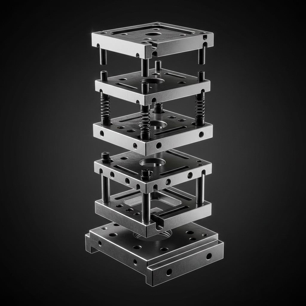
स्टैम्पिंग डाई को एक साधारण उपकरण के बजाय एक सटीक यंत्र के रूप में सोचें। प्रत्येक घटक सामंजस्यपूर्ण रूप से कार्य करता है—गाइड प्रणालियाँ संरेखण बनाए रखती हैं, कटिंग तत्व सामग्री को साफ़-साफ़ अलग करते हैं, और फॉर्मिंग खंड माइक्रोन-स्तर की सटीकता के साथ धातु को आकार देते हैं। जब भी कोई भी घटक विनिर्दिष्ट मानदंड से बाहर हो जाता है, तो आप तुरंत भाग की गुणवत्ता, अपशिष्ट दर या अनपेक्षित अवरोध के रूप में इसका प्रभाव देख सकते हैं।
महत्वपूर्ण डाई घटक और उनके कार्य
एक विशिष्ट स्टैम्पिंग डाई के अंदर क्या होता है? जबकि धातु स्टैम्पिंग मशीनें जटिलता के मामले में भिन्न होती हैं, अधिकांश डाइज़ में ये मूलभूत घटक समान होते हैं:
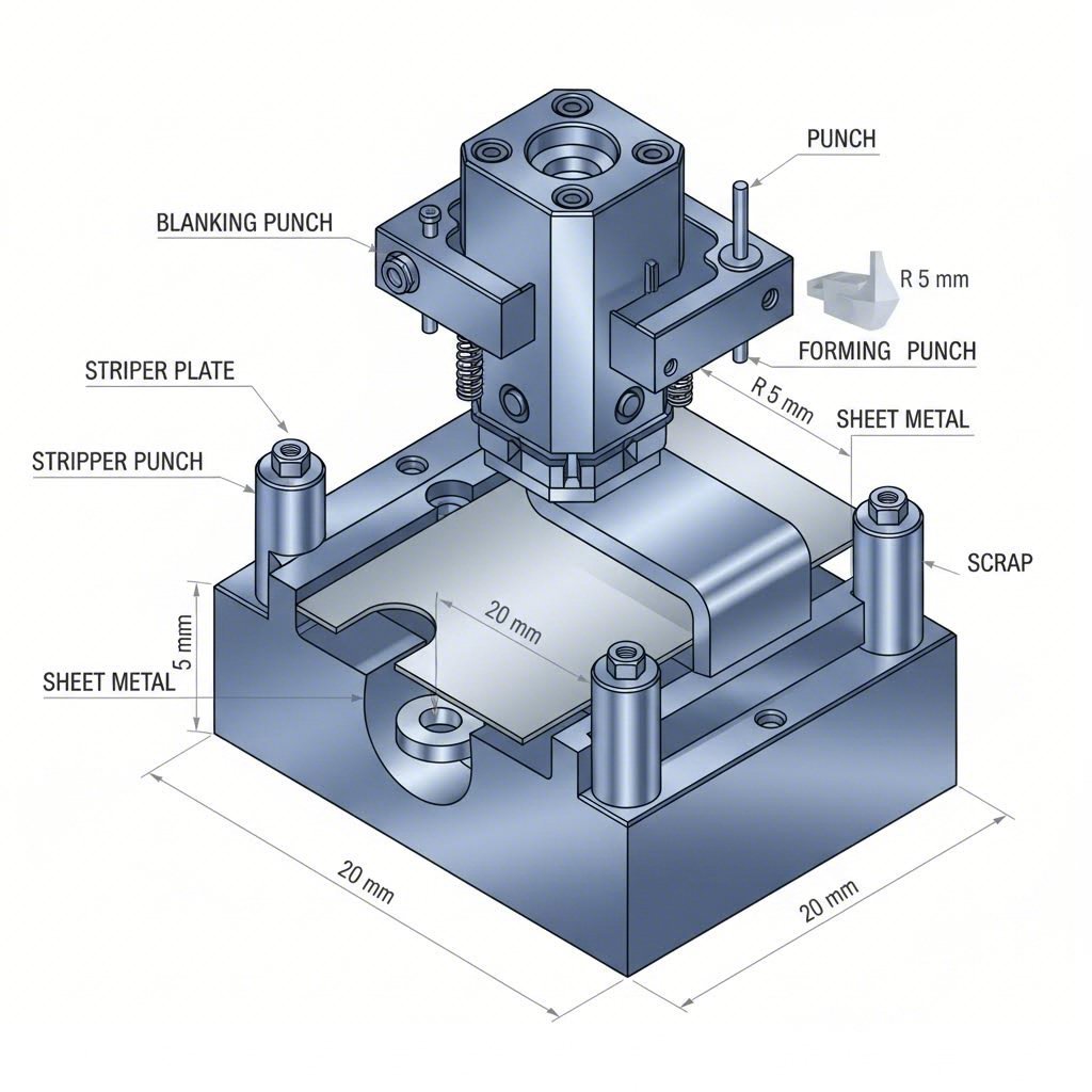
- डाई शू (ऊपरी और निचली): ये मोटी इस्पात की प्लेटें आपके डाई सेट की नींव बनाती हैं, जो सभी अन्य घटकों के लिए स्थिरता और माउंटिंग सतह प्रदान करती हैं। अनुसार, शाओयी मेटल तकनीक दोनों शूज़ को समतलता और समानांतरता सुनिश्चित करने के लिए कड़ी सहिष्णुता के साथ मशीन किया जाता है—ये संदर्भ बिंदु हैं जो संचालन के दौरान विसंरेखण को रोकते हैं।
- पंच प्लेट (पंच रिटेनर): यह कठोर प्लेट काटने और आकार देने वाले पंचों को सटीक स्थितियों में सुरक्षित रखती है। डाउल पिन और हील ब्लॉक नीचे स्थित डाई खुलासों के सापेक्ष सटीक संरेखण को बनाए रखते हैं।
- स्ट्रिपर प्लेट: पंच और कार्य-टुकड़े के बीच स्थित, यह घटक कटाव के दौरान सामग्री को सपाट रखता है और ऊपर की गति (अपस्ट्रोक) के दौरान पंच से इसे अलग कर देता है। स्प्रिंग-लोडेड स्ट्रिपर्स नियंत्रित दबाव प्रदान करते हैं जो भाग के विकृत होने को रोकता है।
- गाइड पिन और बुशिंग: ये सटीक-पॉलिश किए गए घटक प्रत्येक स्ट्रोक पर ऊपरी और निचली डाई आधे हिस्सों के सही ढंग से संरेखित होने को सुनिश्चित करते हैं। जैसा कि उद्योग के विशिष्ट मापदांडों में उल्लेखित है, उच्च-सटीकता अनुप्रयोगों के लिए गाइड पिनों को आमतौर पर 0.0001 इंच के भीतर की सहिष्णुता के अनुसार पॉलिश किया जाता है।
- डाई स्प्रिंग्स: ये विशिष्ट स्प्रिंग्स स्ट्रिपिंग, प्रेशर पैड संचालन और सामग्री नियंत्रण के लिए आवश्यक बल प्रदान करती हैं। लोड क्षमता के आधार पर रंग-कोडित, डाई स्प्रिंग्स को अनुप्रयोग की आवश्यकताओं के सटीक रूप से मेल खाना चाहिए—बहुत हल्की होने पर भाग चिपक जाते हैं; बहुत भारी होने पर आप सामग्री को क्षति पहुँचाने के जोखिम में होते हैं।
डाई स्टील के चयन के बारे में क्या कहा जाए? जिस सामग्री को आप स्टैम्प करते हैं, वह सीधे टूलिंग सामग्री के चयन को प्रभावित करती है। अनुसार, स्टैम्पिंग उद्योग के शोध , उचित टूल स्टील का चयन करने के लिए तीन प्रतिस्पर्धी विशेषताओं—कठोरता (टफनेस), क्षरण प्रतिरोध (वियर रेजिस्टेंस) और संपीड़न सामर्थ्य (कम्प्रेसिव स्ट्रेंथ)—के बीच संतुलन स्थापित करना आवश्यक होता है।
मशीन स्टैम्प अनुप्रयोगों के लिए सामान्य टूल स्टील ग्रेड्स में शामिल हैं:
- A2 टूल स्टील: सामान्य उद्देश्य के अनुप्रयोगों के लिए अच्छी कठोरता और क्षरण प्रतिरोध प्रदान करता है। कठोरण क्षमता के लिए लगभग 5.25% क्रोमियम युक्त है।
- डी2 टूल स्टील: उच्च क्रोमियम सामग्री (12%) स्टेनलेस स्टील और उच्च-शक्ति वाले मिश्र धातुओं जैसी कठोर सामग्रियों के स्टैम्पिंग के लिए उत्कृष्ट पहन-प्रतिरोध प्रदान करती है।
- M2 और M4 उच्च-गति वाली स्टील: जब लेपित सामग्रियों या उच्च-शक्ति वाली स्टील का स्टैम्पिंग किया जाता है, तो ये ग्रेड मांगपूर्ण अनुप्रयोगों के लिए आवश्यक झटका प्रतिरोध और संपीड़न शक्ति का संयोजन प्रदान करते हैं।
- CPM-10V: कण धातुकर्म प्रक्रिया सबसे चुनौतीपूर्ण स्टैम्पिंग वातावरणों के लिए उत्कृष्ट पहन-प्रतिरोध बनाती है।
ऊष्मा उपचार आवश्यकताएँ इन स्टील स्टैम्पिंग डाइज़ की पूर्ण क्षमता को अनलॉक करें। यह प्रक्रिया एक सटीक क्रम का अनुसरण करती है: थर्मल शॉक से बचने के लिए पूर्व-तापन, स्टील की परमाणु संरचना को पुनर्गठित करने के लिए ऑस्टेनाइटाइज़िंग तापमान पर धारण करना, मार्टेन्साइट के निर्माण के लिए तीव्र शीतलन, और कठोरता तथा टैफनेस के बीच संतुलन स्थापित करने के लिए टेम्परिंग। धातु स्टैम्पिंग मशीनों में उपयोग की जाने वाली उच्च-गति वाली उपकरण स्टील के लिए उद्योग मानकों में स्टैम्पिंग संचालनों के लिए अवशिष्ट ऑस्टेनाइट को स्वीकार्य स्तर तक लाने के लिए कम से कम तीन टेम्परिंग चक्रों की आवश्यकता होती है।
सतही कोटिंग घर्षण, क्षरण और सामग्री के चिपकने को कम करके डाई के जीवनकाल को और अधिक बढ़ाएं। सामान्य विकल्पों में शामिल हैं:
- टाइटेनियम नाइट्राइड (TiN): भौतिक वाष्प अवसादन (PVD) द्वारा आवेदित, यह कोटिंग परिशुद्ध उपकरणों के लिए उत्कृष्ट क्षरण प्रतिरोध प्रदान करती है—हालाँकि यह तांबे और स्टेनलेस स्टील के अनुप्रयोगों में कठिनाइयों का सामना कर सकती है।
- टाइटेनियम कार्बोनाइट्राइड (TiCN): यह संकीर्ण अनुप्रयोग सीमा में उच्चतर क्षरण प्रतिरोध प्रदान करती है।
- क्रोमियम नाइट्राइड (CrN): विविध स्टैम्पिंग अनुप्रयोगों के लिए एक अच्छी सामान्य-उद्देश्य कोटिंग।
- थर्मल डिफ्यूजन (TD) कार्बाइड: यह आधार सामग्री से कार्बन का उपयोग करके अत्यंत कठोर सतह परतों का निर्माण करता है—यह उन रूपांतरण अनुप्रयोगों के लिए आदर्श है जहाँ परिशुद्धता की आवश्यकताएँ कम सख्त होती हैं।
उचित रखरखाव के माध्यम से डाई के जीवनकाल का विस्तार
लाखों चक्रों तक निरंतर परिणाम प्रदान करने के लिए भी सर्वोत्तम डिज़ाइन वाली कस्टम धातु स्टैम्पिंग डाई को अनुशासित रखरखाव की आवश्यकता होती है। डाई के जीवनकाल को कौन-कौन से कारक प्रभावित करते हैं?
- जिस सामग्री को स्टैम्प किया जा रहा है: स्टेनलेस स्टील और HSLA ग्रेड जैसी कठोर सामग्रियाँ हल्के इस्पात या तांबे की तुलना में क्षरण को तेज़ी से बढ़ाती हैं।
- स्नेहन प्रथाएँ: उचित लुब्रिकेंट का चयन और आवेदन घर्षण ऊष्मा को कम करता है और टूलिंग तथा कार्य-टुकड़े के बीच गॉलिंग (सतही चिपकना) को रोकता है।
- प्रेस गति: उच्च स्ट्रोक दरें अधिक घर्षण ऊष्मा उत्पन्न करती हैं, जिससे क्षरण तेजी से होता है और भाग की गुणवत्ता प्रभावित हो सकती है।
- रखरखाव की गुणवत्ता: नियमित निरीक्षण और समय पर हस्तक्षेप छोटी समस्याओं को बड़ी विफलताओं में बदलने से रोकते हैं।
अपने स्टैम्पिंग डिज़ाइन और टूलिंग कार्यक्रम के लिए इन मुख्य रखरखाव जाँच बिंदुओं को स्थापित करें:
- शिफ्ट से पहले का निरीक्षण: गाइड पिन्स पर खरोंच की जाँच करें, स्प्रिंग की स्थिति की पुष्टि करें, उचित लुब्रिकेशन सुनिश्चित करें और पंच टिप्स पर दृश्यमान क्षरण या चिपिंग का निरीक्षण करें।
- शार्पनिंग अंतराल: स्टैम्प किए गए भागों पर बर्र की ऊँचाई की निगरानी करें—जब बर्र विनिर्देशों से अधिक हो जाते हैं, तो डाई शार्पनिंग के लिए शेड्यूल बनाएँ। आमतौर पर यह अंतराल सामग्री और टूलिंग विन्यास के आधार पर ५०,००० से ५,००,००० स्ट्रोक के बीच होता है।
- संरेखण सत्यापन: साप्ताहिक रूप से या किसी भी डाई परिवर्तन के बाद पंच-टू-डाई संरेखण की जाँच के लिए परिशुद्धता सूचकों का उपयोग करें। केवल ०.००१ इंच का भी विसंरेखण क्षरण को तेज कर सकता है और भाग की गुणवत्ता को कम कर सकता है।
- घटक का प्रतिस्थापन: स्प्रिंग्स, गाइड बुशिंग्स और स्ट्रिपर घटकों पर घिसावट की निगरानी करें। अनपेक्षित डाउनटाइम से बचने के लिए विफलता से पहले इन्हें बदल दें।
- क्लीयरेंस निगरानी: जैसे-जैसे पंच और डाई बटन घिसते हैं, क्लीयरेंस बढ़ जाता है। नियमित माप सुनिश्चित करता है कि भाग विनिर्देशन के भीतर बने रहें।
आधुनिक इंजीनियरिंग ट्रायल-एंड-एरर को कैसे कम करती है? CAE सिमुलेशन और उन्नत स्टैम्पिंग डिज़ाइन सॉफ़्टवेयर ने डाई विकास को बदल दिया है। उद्योग के विशेषज्ञों द्वारा स्पष्ट किए गए अनुसार, कंप्यूटर-सहायता इंजीनियरिंग (CAE) और परिमित तत्व विश्लेषण (FEA) सॉफ़्टवेयर डिज़ाइनर्स को स्टील के किसी भी टुकड़े को काटे बिना पूरी स्टैम्पिंग प्रक्रिया का डिजिटल रूप से सिमुलेशन करने की अनुमति देते हैं।
ऑटोफॉर्म या डायनाफॉर्म जैसे प्लेटफ़ॉर्म का उपयोग करके, इंजीनियर्स सामग्री प्रवाह की भविष्यवाणी कर सकते हैं, संभावित फॉर्मिंग समस्याओं की पहचान कर सकते हैं और डाई ज्यामिति को आभासी रूप से अनुकूलित कर सकते हैं। इस दृष्टिकोण के कई महत्वपूर्ण लाभ हैं:
- शारीरिक प्रोटोटाइपिंग लागत के बिना त्वरित पुनरावृत्ति
- स्प्रिंगबैक, पतलापन या झुर्रियों की समस्याओं की शुरुआत में पहचान
- कच्चे माल के अपव्यय को कम करने के लिए अनुकूलित ब्लैंक आकृतियाँ
- शारीरिक ट्रायआउट अवधि का संक्षिप्तीकरण
- उच्च प्रथम-प्रयास सफलता दर
परिणाम? त्वरित विकास कालक्रम, कम टूलिंग लागत और ऐसे डाई जो पहली उत्पादन चलाने से ही सही ढंग से कार्य करते हैं। यह सिमुलेशन-प्रथम दृष्टिकोण धातु स्टैम्पिंग उपकरण विकास में वर्तमान कला की उच्चतम सीमा का प्रतिनिधित्व करता है।
टूलिंग के मूलभूत सिद्धांत स्थापित हो जाने के बाद, अगला महत्वपूर्ण विचार गुणवत्ता नियंत्रण है। दोषों को रोकने, प्रक्रियाओं की निगरानी करने और सुसंगत आयामी शुद्धता प्राप्त करने के तरीकों को समझना सुनिश्चित करता है कि आपका सटीक डाई में निवेश वह परिणाम प्रदान करे, जिसकी आपके उत्पादन को आवश्यकता होती है।
गुणवत्ता नियंत्रण और दोष रोकथाम की रणनीतियाँ
आपने सटीक टूलिंग में निवेश किया है और सही सामग्रियों का चयन किया है—लेकिन आप कैसे सुनिश्चित करते हैं कि प्रत्येक स्टैम्प किए गए धातु के घटक विनिर्देशों को पूरा करते हैं? गुणवत्ता नियंत्रण सफल स्टैम्पिंग ऑपरेशन्स को महंगी विफलताओं से अलग करता है। व्यवस्थित निरीक्षण विधियों और दोष रोकथाम की रणनीतियों के बिना, यहाँ तक कि सर्वश्रेष्ठ डाई और प्रेस भी अंततः ऐसे भागों का उत्पादन करेंगे जो ग्राहक की आवश्यकताओं को पूरा नहीं कर पाएँगे। 95% उत्पादन दर और 99.5% उत्पादन दर के बीच का अंतर छोटा प्रतीत हो सकता है, लेकिन लाखों भागों के आधार पर, यह हज़ारों अस्वीकृत घटकों और महत्वपूर्ण वित्तीय प्रभाव के रूप में अभिव्यक्त होता है।
गुणवत्ता नियंत्रण को अपनी विनिर्माण बीमा नीति के रूप में सोचें। अनुसार मेटल इन्फिनिटी सटीक स्टैम्पिंग भागों के लिए आयामी सहनशीलता अक्सर ±0.05 मिमी के आसपास होती है—जो A4 के दो पन्नों की मोटाई के बराबर है। कोई निरीक्षण प्रणाली न होने पर, यह सूक्ष्म अंतर असेंबली संबंधी समस्याओं, गलत स्थान पर लगे स्क्रू या यहाँ तक कि पूरे उपकरण के अवरुद्ध होने का कारण बन सकता है। दोषों के उद्गम स्थान को समझना और उन्हें शुरुआत में ही पकड़ना आपकी प्रतिष्ठा और आपके शुद्ध लाभ दोनों की रक्षा करता है।
सामान्य दोष और मूल कारण विश्लेषण
स्टैम्पिंग संचालन के दौरान क्या गलत होता है? दोषों को पहचानना और उनके कारणों को समझना आपको उत्पादन के अंत में खराब भागों को फ़िल्टर करने के बजाय समस्याओं के मूल स्रोत पर ही उनका समाधान करने में सक्षम बनाता है।
बर्र कटिंग किनारों के साफ-साफ सामग्री को अलग नहीं कर पाने पर बर्स बनते हैं, जिससे भाग की परिधि और छिद्रों के किनारों के साथ उठे हुए किनारे या धातु के टुकड़े छोड़ दिए जाते हैं। HLC मेटल पार्ट्स के अनुसार, बर्स अक्सर तब बनते हैं जब कटिंग उपकरण धातु को पूरी तरह से काटने में विफल रहते हैं, जिससे भाग के किनारे पर कुछ धातु शेष रह जाती है। मूल कारणों में घिसे हुए या कुंद औजार, अत्यधिक पंच-टू-डाई क्लीयरेंस और अनुचित सामग्री चयन शामिल हैं। यदि इन्हें अनदेखा किया जाए, तो बर्स हाथों को काट सकते हैं, संलग्न सतहों को खरोंच सकते हैं और असेंबली में हस्तक्षेप कर सकते हैं।
झिरियाँ जब धातु को उसकी तन्यता सीमा से अधिक तन्य तनाव के अधीन किया जाता है, तो तनाव विफलता होती है। यह विरूपण विफलता आमतौर पर उन स्थानों पर स्थानीय रूप से प्रकट होती है जहां उच्च विकृतियाँ या तनाव केंद्रित होते हैं—विशेष रूप से तीव्र कोनों, छोटी त्रिज्याओं या भारी रूप से आकार दिए गए क्षेत्रों में। इसके योगदानकर्ता कारकों में शामिल हैं:
- आक्रामक फॉर्मिंग ऑपरेशनों के दौरान अत्यधिक विकृति
- आवश्यक विरूपण के लिए पर्याप्त तन्यता के बिना सामग्री
- तनाव संकेंद्रण बिंदुओं का निर्माण करने वाला अनुचित डाई डिज़ाइन
- ठंडे कार्यक्षेत्र में प्रयुक्त सामग्री जो पहले से ही कार्य-कठोरित (वर्क-हार्डनेड) हो चुकी है
झुर्रियाँ यह अनियमित लहरदार आकृतियों या सतह विकृतियों के रूप में प्रकट होता है, विशेष रूप से पतली शीट्स या वक्राकार क्षेत्रों में। जब ड्रॉइंग संचालन के दौरान ब्लैंक होल्डर दाब अपर्याप्त होता है या सामग्री का प्रवाह नियंत्रित नहीं होता है, तो अतिरिक्त धातु डाई के कोष्ठ में सुचारु रूप से प्रवाहित होने के बजाय सिकुड़कर एकत्रित हो जाती है। झुर्रियाँ भाग की शक्ति को कम कर देती हैं, खराब उपस्थिति पैदा करती हैं और अक्सर धातु स्टैम्पिंग घटकों को अउपयोगी बना देती हैं।
स्प्रिंगबैक विचलन यह तब होता है जब निर्मित भाग डाई छोड़ने के बाद अपने मूल समतल आकार की ओर आंशिक रूप से वापस लौट जाते हैं। यह प्रत्यास्थ पुनर्प्राप्ति आयामी शुद्धता को प्रभावित करती है, विशेष रूप से बेंड कोणों पर। उच्च यील्ड सामर्थ्य वाली सामग्रियाँ—विशेष रूप से स्टेनलेस स्टील और एल्यूमीनियम मिश्र धातुएँ—अधिक स्पष्ट स्प्रिंगबैक प्रदर्शित करती हैं, जिसकी डाई डिज़ाइन में क्षतिपूर्ति की आवश्यकता होती है।
सतही खरोंच और तनाव यह टूलिंग और कार्य-टुकड़े की सतहों के बीच घर्षण के कारण होता है। डाई की सतहों के बीच फँसे विदेशी कण, अपर्याप्त स्नेहन या खराब गुणवत्ता वाली टूलिंग की सतह सभी सतही दोषों के कारण बनते हैं। दृश्यमान अनुप्रयोगों के लिए निर्धारित सटीक स्टैम्पिंग भागों के लिए, यहाँ तक कि छोटे से छोटे खरोंच भी अस्वीकृति का कारण बन सकती हैं।
रोकथाम की शुरुआत इस बात को समझने से होती है कि अधिकांश दोष छह मूल कारणों से उत्पन्न होते हैं: अत्यधिक प्रतिबल, अनुचित सामग्री चयन, कटिंग टूल्स का क्षरण, अनुचित डाई डिज़ाइन, गलत स्टैम्पिंग पैरामीटर और अपर्याप्त स्नेहन। इन मूलभूत कारकों को संबोधित करने से अधिकांश गुणवत्ता संबंधित समस्याओं को उनके उत्पन्न होने से पहले ही दूर कर दिया जाता है।
स्थिर आयामी सटीकता प्राप्त करना
आप यह कैसे सत्यापित करते हैं कि उत्पादन के दौरान स्टैम्प किए गए धातु घटक विनिर्देशों को पूरा करते हैं? गुणवत्तापूर्ण धातु स्टैम्पिंग के लिए अंतिम जाँच के साथ-साथ कई चरणों पर व्यवस्थित निरीक्षण की आवश्यकता होती है।
प्रथम लेख निरीक्षण (FAI) गुणवत्तापूर्ण उत्पादन की नींव स्थापित करता है। प्रत्येक उत्पादन चक्र से पहले, एक नमूना भाग का उत्पादन किया जाता है और आकार, बाह्य रूप तथा कार्यक्षमता के संबंध में व्यापक रूप से निरीक्षण किया जाता है। केवल तभी बड़े पैमाने पर उत्पादन शुरू किया जाता है जब प्रथम लेख (फर्स्ट आर्टिकल) सभी विनिर्देशों को पूरा करने की पुष्टि कर ली जाती है। यह प्रोटोकॉल सेटअप की त्रुटियों को उनके हज़ारों भागों में फैलने से पहले पकड़ लेता है।
प्रक्रिया में पर्यवेक्षण उत्पादन के दौरान वास्तविक समय में गुणवत्ता आश्वासन प्रदान करता है। प्रमुख तकनीकें इस प्रकार हैं:
- पैट्रोल निरीक्षण: निरीक्षक उत्पादन लाइन से नियमित रूप से भागों के नमूने लेते हैं—आमतौर पर प्रत्येक 30 मिनट में 5 टुकड़ों की जाँच करके—ताकि प्रक्रिया की स्थिरता की पुष्टि की जा सके।
- सांख्यिकीय प्रक्रिया नियंत्रण (SPC): आयामी डेटा का निरंतर रिकॉर्डिंग, जो नियंत्रण आरेखों (X-बार/आर आरेखों) पर आलेखित किया जाता है, भागों के सहनशीलता सीमा से अधिक होने से पहले ही प्रवृत्तियों को उजागर करता है। यदि डेटा में विचलन की प्रवृत्ति दिखाई देती है, तो ऑपरेटर गैर-विनिर्दिष्ट (आउट-ऑफ-स्पेक) भागों के उत्पादन से पहले ही हस्तक्षेप कर सकते हैं।
- गो/नो-गो मापन: सरल कार्यात्मक गेज बिना सटीक माप के महत्वपूर्ण आयामों की त्वरित पुष्टि करते हैं, जिससे महत्वपूर्ण विशेषताओं का 100% निरीक्षण संभव हो जाता है।
आयामी निरीक्षण विधियाँ सटीक धातु स्टैम्पिंग भागों के लिए शामिल हैं:
- कोऑर्डिनेट मीजरिंग मशीन (सीएमएम): तीन-अक्ष टच प्रोब प्रणालियाँ माइक्रोन-स्तर की सटीकता के साथ जटिल ज्यामितियों को मापती हैं, जिससे महत्वपूर्ण आयामों के लिए विस्तृत आयामी रिपोर्टें उत्पन्न होती हैं।
- 2.5D प्रकाशिक माप: वीडियो माप प्रणालियाँ भागों को छूए बिना समतलीय आयामों, छिद्र व्यासों और स्थिति सटीकता का निरीक्षण करती हैं—नाजुक घटकों के लिए आदर्श।
- प्रकाशिक स्कैनिंग: उन्नत 3D स्कैनिंग पूर्ण भाग ज्यामिति को कैप्चर करती है, जिसकी CAD मॉडल के साथ तुलना की जा सकती है, और संपूर्ण सतहों पर विचलनों को त्वरित रूप से पहचानती है।
- वर्नियर कैलीपर्स और माइक्रोमीटर: पारंपरिक हाथ के उपकरण उत्पादन प्रतिदर्शन के दौरान महत्वपूर्ण आयामों की त्वरित पुष्टि प्रदान करते हैं।
औद्योगिक प्रमाण पत्र गुणवत्ता प्रणालियों की जाँच करें और ग्राहकों को आश्वासन प्रदान करें। ऑटोमोटिव स्टैम्प्ड धातु घटकों के लिए, IATF 16949 प्रमाणन सुनहरा मानक है। OGS इंडस्ट्रीज़ द्वारा उल्लेखित के अनुसार, यह प्रमाणन ISO 9001 की सभी आवश्यकताओं को पूरा करता है—और उससे भी अधिक—जिससे लीन उत्पादन, दोष रोकथाम, विचरण निवारण और अपशिष्ट कमी के लिए अनुपालन सुनिश्चित होता है। IATF 16949 प्रमाणित आपूर्तिकर्ता अपनी दस्तावेज़ीकृत गुणवत्ता प्रबंधन प्रणालियों, प्रक्रिया क्षमता विश्लेषण और निरंतर सुधार के अभ्यासों के माध्यम से स्थिर गुणवत्ता की डिलीवरी करने की क्षमता का प्रदर्शन करते हैं।
अपनी स्टैम्पिंग प्रक्रिया में इन गुणवत्ता जाँच बिंदुओं की स्थापना करें:
- आने वाली सामग्री निरीक्षण: उत्पादन शुरू करने से पहले शीट की मोटाई (आमतौर पर ±0.05 मिमी की सहिष्णुता), सतह की स्थिति और सामग्री के संघटन की पुष्टि करें।
- प्रथम-आइटम अनुमोदन: उत्पादन जारी करने से पहले व्यापक आयामी और कार्यात्मक सत्यापन।
- प्रक्रिया के दौरान नमूनाकरण: AQL (स्वीकार्य गुणवत्ता स्तर) मानकों के आधार पर दस्तावेज़ीकृत नमूना योजनाओं के साथ नियमित पैट्रोल निरीक्षण।
- महत्वपूर्ण आयामों की निगरानी: मुख्य विशेषताओं का SPC ट्रैकिंग, जिसमें नियंत्रण से बाहर की स्थितियों पर तत्काल प्रतिक्रिया की जाती है।
- अंतिम जाँच: पैकेजिंग से पहले आयामी सत्यापन, दृश्य निरीक्षण और कार्यात्मक परीक्षण।
- निर्यात गुणवत्ता नियंत्रण: ग्राहक सत्यापन के लिए बैच-आधारित नमूना लेना और निरीक्षण रिपोर्टों के साथ दस्तावेज़ीकरण।
कौन-सी सहिष्णुताएँ प्राप्त की जा सकती हैं? उचित प्रक्रिया नियंत्रण के साथ, सटीक स्टैम्पिंग आमतौर पर महत्वपूर्ण आयामों पर ±0.05 मिमी से ±0.1 मिमी की सहिष्णुता प्राप्त करती है। विशिष्ट विशेषताओं के लिए अनुकूलित टूलिंग और नियंत्रित प्रक्रियाओं के साथ ±0.03 मिमी तक की कड़ी सहिष्णुताएँ संभव हैं। हालाँकि, इन सटीकता मानकों को प्राप्त करने के लिए पूर्ण गुणवत्ता प्रणाली की आवश्यकता होती है—जो आने वाली सामग्री के सत्यापन से लेकर अंतिम निरीक्षण तक सुसंगत रूप से कार्य करती है।
स्टैम्पिंग में गुणवत्ता नियंत्रण केवल दोषों का पता लगाने के बारे में नहीं है; यह एक बंद-लूप प्रणाली के निर्माण के बारे में है, जहाँ निरीक्षण डेटा निरंतर सुधार को सक्रिय करता है। जब आयामी डेटा प्रवृत्तियों को उजागर करता है, तो इंजीनियर डाई डिज़ाइन को समायोजित करते हैं, सामग्री के चयन को अनुकूलित करते हैं और संचालन पैरामीटर को शार्प करते हैं। यह प्रतिक्रिया लूप गुणवत्ता निरीक्षण को एक लागत केंद्र से एक प्रतिस्पर्धात्मक लाभ में बदल देता है।
गुणवत्ता प्रणालियाँ स्थापित होने के बाद, आप स्टैम्पिंग की तुलना वैकल्पिक निर्माण विधियों से करने के लिए तैयार हैं—और यह समझने के लिए कि जब यह प्रक्रिया आपके विशिष्ट अनुप्रयोग के लिए सर्वोत्तम मूल्य प्रदान करती है।
स्टैम्पिंग बनाम वैकल्पिक निर्माण विधियाँ
आपने गुणवत्ता नियंत्रण पर कब्जा कर लिया है—लेकिन क्या स्टैम्पिंग वास्तव में आपकी परियोजना के लिए सही विकल्प है? टूलिंग निवेश के लिए प्रतिबद्ध होने से पहले, आपको यह समझने की आवश्यकता है कि शीट मेटल स्टैम्पिंग प्रक्रिया प्रतिस्पर्धी प्रौद्योगिकियों के मुकाबले कैसे काम करती है। प्रत्येक विनिर्माण विधि अपने विशिष्ट लाभ प्रदान करती है, और गलत विधि का चयन करने से कम मात्रा के उत्पादन के लिए अधिक भुगतान करना पड़ सकता है या बड़े पैमाने पर उत्पादन के दौरान लाभ को छोड़ना पड़ सकता है।
सच यह है कि कोई भी एकल विनिर्माण प्रक्रिया हर परिस्थिति में प्रभुत्व नहीं जमाती है। सीएनसी मशीनिंग लचीलेपन में उत्कृष्ट है, लेज़र कटिंग टूलिंग लागत को समाप्त कर देती है, कास्टिंग जटिल ज्यामितियों को संभालती है, और फोर्जिंग अतुलनीय शक्ति प्रदान करती है। यह समझना कि स्टैम्प किए गए शीट मेटल कहाँ पर इन वैकल्पिक विधियों को पीछे छोड़ते हैं—और कहाँ नहीं—आपको ऐसे निर्णय लेने की क्षमता प्रदान करता है जो लागत और गुणवत्ता दोनों के अनुकूलन को सुनिश्चित करते हैं।
स्टैम्पिंग परियोजनाओं के लिए लागत सम-आय विश्लेषण
शीट मेटल स्टैम्पिंग कब आर्थिक रूप से उचित विकल्प बन जाती है? इसका उत्तर उत्पादन मात्रा के दहलीज़ मूल्यों, टूलिंग के अवस्करण (amortization) और प्रति भाग लागत वक्रों पर निर्भर करता है, जो विभिन्न निर्माण विधियों के बीच काफी अंतर दर्शाते हैं।
सीएनसी मशीनिंग सीएनसी मशीनिंग स्टैम्पिंग की तुलना में मौलिक रूप से भिन्न दृष्टिकोण अपनाती है। ज़िंटिलॉन के अनुसार, सीएनसी मशीनिंग में कंप्यूटर-नियंत्रित काटने वाले उपकरणों का उपयोग किया जाता है जो कार्य-टुकड़े (workpiece) को आवश्यक आकार में काटते या मिल (mill) करते हैं—यह एक घटात्मक प्रक्रिया है जो सामग्री को हटाती है, बजाय उसके आकार को पुनः निर्मित करने के। यह विधि विशिष्ट परिस्थितियों में उत्कृष्ट प्रदर्शन करती है:
- लचीलापन: कोई टूलिंग निवेश नहीं होने का अर्थ है कि डिज़ाइन में परिवर्तन की लागत केवल प्रोग्रामिंग समय के अतिरिक्त कुछ भी नहीं है।
- प्रसिद्धता: भाग की मात्रा के बावजूद कड़ी सहिष्णुता (tolerances) और जटिल ज्यामिति प्राप्त की जा सकती हैं।
- सामग्री का फैलाव: यह ऐसी धातुओं, प्लास्टिक्स और कॉम्पोजिट्स के साथ काम करता है जिनके साथ स्टैम्पिंग संभव नहीं है।
हालांकि, उत्पादन अनुप्रयोगों के लिए सीएनसी मशीनिंग में काफी बड़े नुकसान हैं। यह प्रक्रिया स्वभाव से धीमी है—प्रत्येक भाग के लिए अलग-अलग मशीनिंग समय की आवश्यकता होती है। सामग्री का अपव्यय काफी बढ़ जाता है, क्योंकि आप सामग्री को काट रहे हैं, न कि उसे पुनर्आकारित कर रहे हैं। जैसा कि ज़िंटिलॉन ने उल्लेख किया है, स्टैम्पिंग उच्च मात्रा में उत्पादन के लिए अत्यधिक कुशल है, जो डाई स्थापित होने के बाद न्यूनतम श्रम के साथ लगातार चलती है, जिससे बड़े उत्पादन बैच के लिए प्रति इकाई लागत कम हो जाती है।
लेजर कटिंग यह पूरी तरह से औजारी (टूलिंग) को समाप्त कर देता है, जिससे यह प्रोटोटाइप और कम मात्रा के लिए आकर्षक हो जाता है। एक केंद्रित लेज़र किरण सीधे शीट धातु से जटिल 2D प्रोफाइल काटती है, बिना किसी डाई या पंच के। समझौता क्या है? लेज़र कटिंग केवल समतल प्रोफाइल तक ही सीमित रहती है—यह मोड़, ड्रॉ या त्रि-आयामी विशेषताओं को नहीं बना सकती है। उन भागों के लिए जिन्हें केवल कटिंग संचालन की आवश्यकता होती है और जो कम से मध्यम मात्रा में निर्मित किए जाते हैं, लेज़र कटिंग आर्थिक रूप से अक्सर शीट धातु प्रक्रिया को पार कर जाती है।
कास्टिंग द्रवित धातु को ढलाई के छाँचों में डालकर जटिल त्रि-आयामी आकृतियाँ बनाता है। यह विधि उन ज्यामितियों को संभाल सकती है जिन्हें प्रेस किए गए शीट स्टील से बनाना असंभव है—जैसे आंतरिक कोष्ठ, चरित्र दीवार मोटाई और कार्गिक आकृतियाँ। हालाँकि, ढलाई में सामान्यतः स्टैम्पिंग की तुलना में कम सटीकता (ढीली सहिष्णुता) प्राप्त होती है, सटीक सतहों के लिए द्वितीयक मशीनिंग की आवश्यकता होती है, और उन मात्राओं पर प्रति भाग लागत अधिक होती है जहाँ स्टैम्पिंग अधिक कुशल होती है।
बनाना गर्म या ठंडी सामग्री को आकार देने के लिए संपीड़ित करके सबसे मजबूत धातु के घटकों का निर्माण करता है। फोर्ज किए गए भागों में स्टैम्प किए गए विकल्पों की तुलना में उत्कृष्ट दाना संरचना और यांत्रिक गुण होते हैं। इस उच्च गुणवत्ता के साथ एक मूल्य भी जुड़ा है: फोर्जिंग संचालन की प्रति भाग लागत काफी अधिक होती है और इसके लिए महत्वपूर्ण औजारों के निवेश की आवश्यकता होती है—इसलिए यह विधि उच्च-तनाव वाले अनुप्रयोगों के लिए सबसे उपयुक्त है, जहाँ सामग्री की शक्ति इस अतिरिक्त व्यय को औचित्यपूर्ण बनाती है।
तो विराम बिंदु कहाँ है? के अनुसार स्विट्ज़र निर्माण स्टैम्पिंग की लागत में लाभ वार्षिक उत्पादन मात्रा 50,000 से 100,000 भागों के ऊपर जाने पर शुरू हो सकते हैं, जहाँ विशिष्ट क्रॉसओवर बिंदु व्यक्तिगत भागों की विशेषताओं पर अत्यधिक निर्भर करता है। बड़ी विशेषताओं वाले सरल भागों के लिए स्टैम्पिंग कम मात्रा में भी लाभदायक हो सकती है, क्योंकि डाई की लागत नगण्य रहती है। जटिल विवरणों वाले भागों का उत्पादन वैकल्पिक विधियों द्वारा 500,000 टुकड़ों प्रति वर्ष की मात्रा पर भी अधिक आर्थिक रह सकता है।
यह विश्लेषण टूलिंग के अपलिखन (एमोर्टाइज़ेशन) की गणना पर आधारित है। मान लीजिए कि एक प्रोग्रेसिव डाई की लागत $50,000 है। 10,000 भागों के लिए, केवल टूलिंग की पुनर्प्राप्ति के लिए प्रति भाग $5.00 की लागत आती है। 100,000 भागों के लिए, टूलिंग का योगदान घटकर प्रति भाग $0.50 हो जाता है। 1,000,000 भागों के लिए, यह प्रति भाग केवल $0.05 हो जाता है, जो व्यावहारिक रूप से नगण्य है। इस बीच, सीएनसी मशीनिंग की प्रति भाग लागत मात्रा के बावजूद स्थिर रहती है—इसलिए, एक बार जब आप दोनों लागत वक्रों को जान लेते हैं, तो क्रॉसओवर बिंदु की भविष्यवाणी करना संभव हो जाता है।
| निर्माण विधि | सेटअप लागत | मात्रा के अनुसार प्रति भाग लागत | ज्यामितीय जटिलता | सहनशीलता क्षमता | आदर्श मात्रा सीमा |
|---|---|---|---|---|---|
| शीट मेटल स्टैंपिंग | उच्च ($20,000–$150,000+ टूलिंग के लिए) | पैमाने पर बहुत कम | मध्यम; आकार बनाने योग्य आकृतियों तक सीमित | ±0.05 मिमी से ±0.15 मिमी तक | वार्षिक 50,000+ |
| सीएनसी मशीनिंग | निम्न (केवल प्रोग्रामिंग) | उच्च; प्रति भाग स्थिर | अत्यधिक उच्च; जटिल 3D क्षमता वाला | ±0.01 मिमी से ±0.05 मिमी | 1 से 10,000 भाग |
| लेजर कटिंग | अत्यंत कम (कोई टूलिंग नहीं) | मध्यम; जटिलता पर निर्भर | 2D के लिए उच्च; कोई आकृति निर्माण नहीं | ±0.1मिमी से ±0.25मिमी | 1 से 50,000 भाग |
| कास्टिंग | मध्यम से उच्च (मोल्ड लागत) | मध्यम | अत्यधिक उच्च; आंतरिक विशेषताएँ संभव | ±0.25मिमी से ±1.0मिमी | 500–100,000 भाग |
| बनाना | उच्च (डाई की लागत) | उच्च | मध्यम; डाई तक पहुँच की सीमा के कारण | ±0.1मिमी से ±0.5मिमी | 1,000–500,000 भाग |
उपकरण निर्माण लागत को कम करने वाले डिज़ाइन संशोधन
जब आपने निर्धारित कर लिया है कि निर्माण स्टैम्पिंग प्रक्रिया आपकी मात्रा आवश्यकताओं के अनुरूप है, तो निर्माण के लिए डिज़ाइन (DFM) के सिद्धांतों का उपयोग उपकरण निवेश और प्रति भाग लागत दोनों को काफी कम कर सकता है। छोटे डिज़ाइन परिवर्तन अक्सर कार्यक्षमता को समझौता किए बिना महत्वपूर्ण बचत प्रदान करते हैं।
न्यूनतम बेंड रेडियस दरारों को रोकने और उपकरण जटिलता को कम करने के लिए। सामान्य नियम के अनुसार, नरम सामग्रियों जैसे एल्यूमीनियम और तांबे के लिए आंतरिक बेंड त्रिज्या कम से कम सामग्री की मोटाई के बराबर होनी चाहिए। स्टेनलेस स्टील जैसी कठोर सामग्रियों के लिए, आंतरिक त्रिज्या को सामग्री की मोटाई के 1.5 से 2 गुना के रूप में निर्दिष्ट करें। अधिक तंग बेंड के लिए अधिक उन्नत उपकरणों की आवश्यकता होती है, जो आकार देने के बल में वृद्धि करते हैं और सामग्री विफलता का जोखिम उत्पन्न करते हैं।
छेद से किनारे की दूरी दोनों डाई के जीवनकाल और भाग की गुणवत्ता को प्रभावित करते हैं। ब्लैंकिंग के दौरान विकृति को रोकने के लिए छिद्रों को भाग के किनारों से कम से कम 1.5 गुना सामग्री की मोटाई की दूरी पर स्थित करें। अधिक निकट स्थिति छिद्र और किनारे के बीच की सामग्री को कमजोर कर देती है, जिससे फॉर्मिंग संचालन के दौरान या सेवा के दौरान टियर-आउट होने की संभावना बढ़ जाती है।
छेद से छेद की दूरी इसका तर्क समान है। पंचों के बीच सामग्री की अखंडता को बनाए रखने के लिए आसन्न छिद्रों के बीच कम से कम 2 गुना सामग्री की मोटाई का अंतर बनाए रखें। अधिक निकट स्थिति डाई की जटिलता बढ़ाती है और टूल के जीवनकाल को कम करती है।
द्रष्टि कोण फॉर्मिंग डाइज़ से भाग के निकास को सुगम बनाने के लिए आवश्यक है। जबकि स्टैम्पिंग के लिए डाई कास्टिंग या मोल्डिंग की तुलना में कम ड्राफ्ट की आवश्यकता होती है, ऊर्ध्वाधर दीवारों पर हल्के कोण (आमतौर पर 1–3 डिग्री) भागों को डाई कैविटीज़ से साफ़ और चिपकने या सतह क्षति के बिना निकलने में सहायता करते हैं।
सामग्री उपयोग का अनुकूलन प्रति-भाग लागत को सीधे प्रभावित करता है। शीट धातु स्टैम्पिंग डिज़ाइन प्रक्रिया में ब्लैंक लेआउट की दक्षता पर विचार करना चाहिए—अर्थात्, एक शीट या कॉइल चौड़ाई के भीतर न्यूनतम कचरा छोड़कर कितने भागों को समायोजित (नेस्ट) किया जा सकता है। कभी-कभी छोटे आयामी समायोजन सामग्री के उपयोग में उल्लेखनीय सुधार का कारण बनते हैं। यदि कोई ब्रैकेट 98 मिमी चौड़ा है, तो उसके 95 मिमी चौड़ाई में पुनर्डिज़ाइन करने से नेस्टिंग दक्षता में सुधार हो सकता है, जिससे प्रति भाग सामग्री का उपयोग 30% कम हो जाएगा।
विशेषता संयोजन डाई स्टेशनों और फॉर्मिंग संचालन को कम करता है। अलग-अलग घटकों को डिज़ाइन करने के बजाय, जिन्हें संयोजित करने की आवश्यकता होती है, यह विचार करें कि क्या एकल स्टैम्प्ड भाग में कई कार्यों को शामिल किया जा सकता है। प्रत्येक समाप्त किए गए संयोजन संचालन से श्रम लागत बचत होती है और संभावित गुणवत्ता संबंधी समस्याएँ कम हो जाती हैं।
गहरे ड्रॉ (डीप ड्रॉ) से जहाँ भी संभव हो, बचना चाहिए। उथले आकारण कार्यों के लिए कम प्रेस टनेज, सरल औजारी और गहरे ड्रॉ की तुलना में तेज़ चलने की आवश्यकता होती है। यदि आपके डिज़ाइन में काफी गहराई की आवश्यकता है, तो विचार करें कि क्या वह गहराई कार्यात्मक रूप से आवश्यक है या केवल पिछली निर्माण विधियों से अपनाई गई एक विशेषता है।
ये शीट धातु प्रेस विचार एक साथ कार्य करते हैं। निर्माण स्टैम्पिंग प्रक्रिया के लिए अच्छी तरह से अनुकूलित डिज़ाइन, DFM सिद्धांतों के बिना डिज़ाइन किए गए कार्यात्मक रूप से समान भाग की तुलना में 20–40% कम लागत पर उत्पादित किया जा सकता है। यह अंतर उत्पादन मात्रा के साथ संचयित होता है—बचत प्रत्येक उत्पादित भाग के साथ गुणजित होती जाती है।
इन लागत गतिशीलताओं और डिज़ाइन सिद्धांतों को समझना आपको स्टैम्पिंग अवसरों का सही तरीके से मूल्यांकन करने में सक्षम बनाता है। लेकिन केवल सिद्धांत तक ही सीमित रहता है। अगले खंड में, हम इन सिद्धांतों के एक सबसे चुनौतीपूर्ण अनुप्रयोग—ऑटोमोटिव निर्माण—में उनके प्रयोग का अध्ययन करेंगे, जहाँ गुणवत्ता मानक, उत्पादन मात्रा और विकास के समय-सीमा इस प्रौद्योगिकी को उसकी सीमाओं तक धकेल देते हैं।
ऑटोमोटिव स्टैम्पिंग अनुप्रयोग और उद्योग मानक
आपने स्टैम्पिंग के मूल सिद्धांतों का पता लगाया है, विनिर्माण विधियों की तुलना की है और लागत गतिशीलता को समझा है—लेकिन यह ज्ञान अपनी अंतिम परीक्षा कहाँ पाता है? ऑटोमोटिव उद्योग में। कोई भी क्षेत्र धातु स्टैम्पिंग विनिर्माण को इतनी चरम सीमाओं तक नहीं धकेलता: कड़े टॉलरेंस, उच्च उत्पादन मात्रा, कठोर गुणवत्ता आवश्यकताएँ, और विकास के समय-सीमा को तेज़ करने के लिए लगातार दबाव। ऑटोमोटिव स्टैम्पिंग के कार्यप्रणाली को समझना, स्टैम्पिंग विनिर्माण की पूर्ण क्षमता को एक सटीक उत्पादन प्रौद्योगिकि के रूप में उजागर करता है।
पैमाने पर विचार करें: एक वाहन में ३०० से ५०० स्टैम्प किए गए घटक होते हैं, जो विशाल बॉडी पैनल्स से लेकर छोटे से छोटे ब्रैकेट्स तक होते हैं। इसे वार्षिक उत्पादन मात्रा—जो लाखों वाहनों तक पहुँच जाती है—से गुणा करें, और आप समझने लगेंगे कि ऑटोमोटिव धातु स्टैम्पिंग में पूर्ण स्थिरता क्यों आवश्यक है। अन्य उद्योगों में स्वीकार्य दोष दर, ऑटोमोटिव उत्पादन मात्रा के संदर्भ में व्यापक रूप से विनाशकारी हो जाती है।
ओईएम गुणवत्ता मानकों की पूर्ति
ऑटोमोटिव स्टैम्पिंग को सामान्य विनिर्माण से क्या अलग करता है? इसका उत्तर प्रमाणन आवश्यकताओं से शुरू होता है, जो एक भी भाग के उत्पादन से पहले ही आपूर्तिकर्ताओं का चयन करती हैं।
IATF 16949 प्रमाणन ऑटोमोटिव आपूर्ति श्रृंखलाओं में प्रवेश का प्रमाणपत्र है। अनुसार उद्योग विश्लेषण , जबकि आईएसओ 9001 सामान्य गुणवत्ता प्रबंधन के लिए एक आधारभूत स्तर निर्धारित करता है, यह ऑटोमोटिव ओईएम और टियर-1 आपूर्तिकर्ताओं की कठोर आवश्यकताओं के लिए पर्याप्त नहीं है। आईएटीएफ 16949 उद्योग का मानक है, जो विशेष रूप से ऑटोमोटिव आपूर्ति श्रृंखला में दोषों को रोकने, विचरण को कम करने और अपव्यय को न्यूनतम करने के लिए डिज़ाइन किया गया है।
यह प्रमाणन केवल दस्तावेज़ीकरण से अधिक है। एक आईएटीएफ-प्रमाणित आपूर्तिकर्ता ने निम्नलिखित प्रणालियों का प्रदर्शन किया है:
- सुरक्षा-महत्वपूर्ण घटकों को पूर्ण ट्रेसैबिलिटी के साथ संभालना
- ब्रेक घटकों और चेसिस मजबूतीकरण जैसे भागों के लिए जोखिम प्रबंधन प्रोटोकॉल लागू करना
- दोष का पता लगाने की बजाय दोष रोकथाम के दृष्टिकोण को बनाए रखना
- प्रमुख ओईएम से ग्राहक-विशिष्ट आवश्यकताओं की पूर्ति करना
उत्पादन भाग स्वीकृति प्रक्रिया (पीपीएपी) यह सत्यापित करता है कि आपूर्तिकर्ता की धातु स्टैम्पिंग विनिर्माण प्रक्रिया वास्तविक उत्पादन चलाने के दौरान सभी आवश्यकताओं को पूरा करने वाले भागों का लगातार उत्पादन कर सकती है। इस कठोर प्रलेखन पैकेज—जिसमें आयामी परिणाम, सामग्री प्रमाणन, क्षमता अध्ययन और नियंत्रण योजनाएँ शामिल हैं—को बड़े पैमाने पर उत्पादन शुरू करने से पहले मंजूरी दे दी जानी चाहिए।
उन्नत उत्पाद गुणवत्ता योजना (APQP) यह अवधारणा से लेकर उत्पादन लॉन्च तक पूरी विकास प्रक्रिया को संरचित करता है। यह ढांचा सुनिश्चित करता है कि संभावित समस्याओं की पहचान और उनका समाधान योजना बनाने के दौरान किया जाए, न कि उत्पादन के दौरान उनकी खोज की जाए।
प्रदर्शन की अपेक्षाएँ? उद्योग के मानकों के अनुसार, शीर्ष-स्तरीय ऑटोमोटिव स्टैम्पर्स 0.01% (100 PPM) तक के अत्यंत कम अस्वीकृति दर प्राप्त करते हैं, जबकि औसत आपूर्तिकर्ताओं की अस्वीकृति दर लगभग 0.53% (5,300 PPM) के आसपास होती है। यह अंतर सीधे असेंबली लाइन की विश्वसनीयता को प्रभावित करता है—सुचारू उत्पादन और महंगे उत्पादन बंद होने के बीच का अंतर।
ऑटोमोटिव अनुप्रयोगों के लिए उच्च मात्रा वाले धातु स्टैम्पिंग की आवश्यकता विशिष्ट तकनीकी क्षमताओं को भी लगातार पूरा करने की मांग करती है। प्रेस टनेज की आवश्यकताएँ आमतौर पर 100 से 600+ टन के बीच होती हैं, ताकि दोनों ही—सटीक ब्रैकेट्स और नियंत्रण भुजाएँ या सबफ्रेम जैसे बड़े संरचनात्मक घटकों—को संभाला जा सके। आंतरिक टूलिंग क्षमताएँ महत्वपूर्ण हो जाती हैं—जब कोई डाई उत्पादन के दौरान टूट जाती है, तो इसे मरम्मत के लिए बाहर भेजने में दिनों या सप्ताह लग सकते हैं, जबकि आंतरिक टूल शॉप्स अक्सर समस्याओं को घंटों में ही ठीक कर देती हैं।
आपूर्तिकर्ता जैसे शाओयी मेटल तकनीक आधुनिक स्टैम्पिंग डाई प्रदाताओं द्वारा इन चुनौतीपूर्ण आवश्यकताओं को कैसे पूरा किया जाता है, इसका उदाहरण यहाँ दिया गया है। उनकी IATF 16949-प्रमाणित सुविधा 600 टन तक की क्षमता वाली प्रेसों का उपयोग करती है, जिससे ओईएम-स्तरीय सटीकता के साथ महत्वपूर्ण सुरक्षा घटकों का उत्पादन संभव होता है। उनकी इंजीनियरिंग टीम के पास उन्नत CAE सिमुलेशन क्षमताएँ हैं, जिनके द्वारा वे स्टील काटने से पहले सामग्री प्रवाह की भविष्यवाणी कर सकते हैं, संभावित फॉर्मिंग समस्याओं की पहचान कर सकते हैं और डाई की ज्यामिति को अनुकूलित कर सकते हैं—जिससे प्रयोग-और-त्रुटि की आवश्यकता कम होती है और उत्पादन शुरू करने का समय कम हो जाता है।
त्वरित प्रोटोटाइपिंग के साथ विकास को तेज करना
ऑटोमोटिव विकास चक्र अत्यधिक संकुचित हो गए हैं। जो वाहन कार्यक्रम पहले पाँच वर्षों तक फैले हुए थे, वे अब तीन वर्षों में पूरे हो जाते हैं। इस त्वरण के कारण स्टैम्पिंग निर्माण के समय-सीमा पर तीव्र दबाव उत्पन्न होता है—जिस टूलिंग के विकास के लिए पहले १८ महीने का समय लगता था, उसे अब उससे आधे समय में उत्पादन-तैयार बनाना होता है।
त्वरित प्रोटोटाइपिंग डिज़ाइन अवधारणाओं और उत्पादन सत्यापन के बीच के अंतर को पाटती है। उद्योग के विशेषज्ञों के अनुसार, त्वरित प्रोटोटाइपिंग मानक विकास समय-सीमा से दिनों, सप्ताहों या महीनों को कम करने में सहायता करने वाले लागत-कुशल मॉडल तेज़ी से प्रदान करती है। जब उत्पाद डिज़ाइनरों के पास अंतहीन परिकल्पना करने का समय नहीं होता है, तो अंतिम उत्पादों की तरह बनाए गए और अत्यधिक सटीक प्रोटोटाइप त्वरित निर्णय लेने को सक्षम बनाते हैं।
लाभ केवल गति तक ही सीमित नहीं हैं:
- डिज़ाइन की पुष्टि: भौतिक प्रोटोटाइप वे मुद्दे प्रकट करते हैं जिन्हें CAD मॉडल याद कर लेते हैं—फिटिंग की समस्याएँ, अप्रत्याशित स्प्रिंगबैक, असेंबली में हस्तक्षेप।
- प्रक्रिया सुधार: प्रोटोटाइप टूलिंग पर फॉर्मिंग अनुक्रमों का परीक्षण करने से उत्पादन डाई निवेश से पहले इष्टतम पैरामीटरों की पहचान की जा सकती है।
- ग्राहक की मंजूरी: ओईएम ड्रॉइंग्स और सिमुलेशन के आधार पर निर्णय लेने के बजाय वास्तविक पार्ट्स का मूल्यांकन कर सकते हैं।
- जोखिम कम करना: प्रोटोटाइपिंग के दौरान डिज़ाइन की कमियाँ पकड़ना उत्पादन लॉन्च के दौरान उन्हें खोजने की तुलना में काफी कम लागत वाला होता है।
व्यावहारिक प्रभाव पर विचार करें: एकीकृत प्रोटोटाइपिंग क्षमताओं वाले उत्पादन धातु स्टैम्पिंग आपूर्तिकर्ता प्रारंभिक नमूने को केवल पाँच दिनों के भीतर डिलीवर कर सकते हैं। यह गति पहले केवल एक डिज़ाइन पुनरावृत्ति की अनुमति देने वाले समय-सीमा के भीतर कई डिज़ाइन पुनरावृत्तियों की अनुमति देती है—जिससे अंतिम पार्ट की गुणवत्ता में काफी सुधार होता है और समग्र विकास कार्यक्रम को संकुचित किया जाता है।
शाओयी का दृष्टिकोण यह दर्शाता है कि अग्रणी आपूर्तिकर्ता त्वरित प्रोटोटाइपिंग को उत्पादन स्टैम्पिंग के साथ कैसे एकीकृत करते हैं। उनकी इंजीनियरिंग टीम कुछ दिनों के भीतर ५० भागों का उत्पादन करने में सक्षम प्रोटोटाइप टूलिंग प्रदान करती है, जिससे ग्राहक पूर्ण उत्पादन डाईज़ पर प्रतिबद्ध होने से पहले अपने डिज़ाइनों का मान्यन कर सकते हैं। यह प्रोटोटाइप-से-उत्पादन क्षमता—जो ९३% प्रथम-पास मंजूरी दर के साथ संयुक्त है—उन महंगे पुनरावृत्तियों को कम करती है जो कई असंबद्ध आपूर्तिकर्ताओं द्वारा प्रबंधित स्टैम्पिंग कार्यक्रमों को प्रभावित करती हैं।
ऑटोमोटिव स्टैम्पिंग का परिदृश्य लगातार विकसित हो रहा है। हल्के वजन के प्रयासों के कारण उच्च-शक्ति वाले इस्पात और एल्यूमीनियम मिश्र धातुओं का उपयोग बढ़ रहा है, जिनके लिए अधिक उन्नत फॉर्मिंग तकनीकों की आवश्यकता होती है। इलेक्ट्रिक वाहन (EV) प्लेटफॉर्म नए घटक ज्यामिति और सामग्री आवश्यकताओं को प्रस्तुत करते हैं। इन सभी परिवर्तनों के बावजूद, मूल आवश्यकताएँ अपरिवर्तित बनी हुई हैं: सटीक टूलिंग, प्रमाणित गुणवत्ता प्रणालियाँ, और ऐसे आपूर्तिकर्ता जो अवधारणा से लेकर उच्च-मात्रा उत्पादन तक बिना किसी बाधा के संचालित हो सकें।
निर्माताओं के लिए जो स्टैम्पिंग साझेदारों का मूल्यांकन कर रहे हैं, ऑटोमोटिव क्षेत्र एक उपयोगी मानक प्रदान करता है। ऑटोमोटिव आवश्यकताओं को पूरा करने वाले आपूर्तिकर्ता—IATF 16949 प्रमाणन, सिद्ध PPAP प्रक्रियाएँ, एकीकृत प्रोटोटाइपिंग क्षमताएँ, और दस्तावेज़ीकृत गुणवत्ता मेट्रिक्स—प्रत्येक परियोजना में उसी कठोरता को लागू करते हैं। चाहे आपका अनुप्रयोग ऑटोमोटिव मात्रा में हो या अधिक सीमित उत्पादन चलाने में, ऑटोमोटिव-योग्य आपूर्तिकर्ताओं के साथ साझेदारी से आपका स्टैम्पिंग कार्यक्रम उद्योग के सबसे माँग वाले मानकों से लाभान्वित होता है।
ऑटोमोटिव अनुप्रयोगों के माध्यम से स्टैम्पिंग की पूर्ण क्षमता को दर्शाते हुए, आप अब अपनी विशिष्ट परियोजना के लिए सभी शामिल विषयों को व्यावहारिक मार्गदर्शन में संश्लेषित करने के लिए तैयार हैं। अंतिम खंड एक निर्णय रूपरेखा प्रदान करता है जो आपको यह मूल्यांकन करने में सहायता करेगी कि क्या स्टैम्पिंग आपकी आवश्यकताओं के अनुरूप है और सही विनिर्माण साझेदार का चयन कैसे किया जाए।
अपनी परियोजना के लिए सही स्टैम्पिंग निर्णय लेना
आपने स्टैम्पिंग निर्माण प्रक्रिया की पूरी यात्रा तय की है—मूल यांत्रिकी से लेकर ऑटोमोटिव-ग्रेड गुणवत्ता प्रणालियों तक। अब महत्वपूर्ण प्रश्न आता है: आप इस ज्ञान को सफल परियोजना कार्यान्वयन में कैसे बदलेंगे? चाहे आप कोई नया उत्पाद लॉन्च कर रहे हों या मौजूदा उत्पादन को अनुकूलित कर रहे हों, शुरुआत में लिए गए निर्णय वर्षों तक के परिणामों को निर्धारित करते हैं।
सच यह है कि धातु स्टैम्पिंग की सफलता शायद ही कभी किसी एक शानदार निर्णय पर निर्भर करती है। बल्कि, यह आपस में जुड़े कारकों को प्रणालीगत रूप से संबोधित करने से उभरती है: आवेदन की आवश्यकताओं के अनुरूप सामग्री का चयन करना, मात्रा और जटिलता के अनुरूप प्रक्रिया प्रकारों का चयन करना, फॉर्मिंग आवश्यकताओं के अनुरूप प्रेस क्षमताओं का मिलान करना, और ऐसी गुणवत्ता प्रणालियाँ लागू करना जो निरंतर परिणाम प्रदान करें। किसी भी तत्व को छोड़ देने पर, आप उन समस्याओं का सामना करेंगे जिन्हें रोका जा सकता था।
आपकी स्टैम्पिंग परियोजना मूल्यांकन जाँच सूची
संभावित आपूर्तिकर्ताओं के साथ संलग्न होने या टूलिंग निवेश पर प्रतिबद्ध होने से पहले, इन आवश्यक निर्णय आधारों पर विचार करें। प्रत्येक प्रश्न पिछले अध्यायों से प्राप्त अंतर्दृष्टियों पर आधारित है, जिससे परियोजना मूल्यांकन के लिए एक व्यापक ढांचा तैयार होता है।
- मात्रा मूल्यांकन: आपको प्रति वर्ष कितनी मात्रा की आवश्यकता है? धातु स्टैम्पिंग आमतौर पर वार्षिक 50,000 टुकड़ों से अधिक के लिए लागत-प्रभावी हो जाती है, हालाँकि सरल भागों के लिए ब्रेक-ईवन बिंदु कम मात्रा पर भी हो सकता है। यदि आपको 10,000 से कम भागों की आवश्यकता है, तो विचार करें कि क्या सीएनसी मशीनिंग या लेज़र कटिंग अधिक आर्थिक रूप से फायदेमंद है।
- सामग्री के आवश्यकताएँ: क्या आपके अनुप्रयोग में विशिष्ट गुणों—जैसे संक्षारण प्रतिरोध, विद्युत चालकता, उच्च शक्ति-से-भार अनुपात—की आवश्यकता है? सबसे पहले कार्यात्मक आवश्यकताओं के अनुसार सामग्री का चयन करें, फिर उसकी स्टैम्पिंग योग्यता की पुष्टि करें। ध्यान रखें कि एल्यूमीनियम के लिए स्प्रिंगबैक कॉम्पेंसेशन की आवश्यकता होती है, जबकि स्टेनलेस स्टील तेज़ी से वर्क-हार्डन हो जाती है।
- ज्यामितीय जटिलता: यह मूल्यांकन करें कि क्या आपके भाग की ज्यामिति प्रगतिशील मॉल्ड (मध्यम जटिलता, उच्च मात्रा), ट्रांसफर मॉल्ड (बड़े भाग, गहरे ड्रॉ) या फोरस्लाइड प्रणालियों (जटिल छोटे भाग) के लिए उपयुक्त है। जटिल ज्यामितियाँ टूलिंग लागत को बढ़ा देती हैं, लेकिन कई घटकों को एक में समेकित कर सकती हैं।
- सहिष्णुता विनिर्देश: महत्वपूर्ण आयामों और स्वीकार्य सहिष्णुताओं को शुरू में ही परिभाषित करें। सटीक स्टैम्पिंग आवश्यक विशेषताओं पर ±0.05 मिमी की सटीकता प्राप्त कर सकती है, लेकिन कठोर सहिष्णुताएँ टूलिंग की जटिलता और निरीक्षण आवश्यकताओं को बढ़ा देती हैं। केवल उन्हीं विशेषताओं को निर्दिष्ट करें जो वास्तव में कार्यात्मक रूप से आवश्यक हों।
- आवश्यक गुणवत्ता प्रमाणन: निर्धारित करें कि क्या आपके क्षेत्र के लिए विशिष्ट प्रमाणन अनिवार्य हैं। ऑटोमोटिव अनुप्रयोगों के लिए IATF 16949-प्रमाणित आपूर्तिकर्ताओं की आवश्यकता होती है। चिकित्सा और एयरोस्पेस क्षेत्रों के अपने स्वयं के मानक होते हैं। शुरू में ही प्रमाणित आपूर्तिकर्ताओं का चयन करने से बाद में योग्यता प्रक्रिया में देरी रोकी जा सकती है।
- विकास कालावधि: आपको उत्पादन तक कितनी जल्दी पहुँचना आवश्यक है? कुछ आपूर्तिकर्ताओं द्वारा केवल 5 दिनों में प्रारंभिक नमूने प्रदान करने की क्षमता के साथ तीव्र प्रोटोटाइपिंग क्षमताएँ विकास चक्रों को काफी कम कर देती हैं। अपने कार्यक्रम में प्रोटोटाइप पुनरावृत्तियों को शामिल करें।
- द्वितीयक कार्य: स्टैम्पिंग के बाद की आवश्यकताओं की पहचान करें: प्लेटिंग, वेल्डिंग, असेंबली, ऊष्मा उपचार। एकीकृत द्वितीयक संचालन प्रदान करने वाले आपूर्तिकर्ता लॉजिस्टिक्स की जटिलता और गुणवत्ता हस्तांतरण जोखिमों को कम करते हैं।
- कुल लागत विश्लेषण: प्रति-भाग मूल्य से आगे देखें। अपनी गणनाओं में टूलिंग का अवमूल्यन, अपव्यय दरें, गुणवत्ता लागतें और विकास व्यय शामिल करें। 99%+ गुणवत्ता वाले आपूर्तिकर्ता से थोड़ी उच्च प्रति-भाग लागत कुल मिलाकर कम लागत वाली हो सकती है, जबकि 5% अस्वीकृति दर वाले कम उद्धरण की तुलना में।
लार्सन टूल एंड स्टैम्पिंग के अनुसार, संभावित आपूर्तिकर्ताओं का मूल्यांकन करते समय कई महत्वपूर्ण क्षेत्रों की जांच करनी चाहिए: गुणवत्ता प्रमाणन, मापने योग्य प्रदर्शन उद्देश्य, क्षमताओं में पुनर्निवेश, आपूर्ति श्रृंखला संबंध, कार्यबल प्रशिक्षण कार्यक्रम और सुव्यवस्थित सुविधा। कोई भी अच्छी तरह से प्रबंधित स्टैम्पिंग कंपनी के पास यह जानकारी तुरंत उपलब्ध होनी चाहिए—यदि ऐसा नहीं है, तो इसे उनकी समग्र क्षमताओं के बारे में एक चेतावनि संकेत माना जाना चाहिए।
सही टूलिंग विशेषज्ञों के साथ साझेदारी
यहाँ वह क्या है जो सफल स्टैम्पिंग कार्यक्रमों को समस्याग्रस्त कार्यक्रमों से अलग करता है: आपूर्तिकर्ता से जुड़ाव का समय। जैसा कि माइक्रो-ट्रॉनिक्स द्वारा उजागर किया गया है, प्रारंभिक चरणों में डिज़ाइन में संशोधन करना अपेक्षाकृत आसान और लागत-प्रभावी होता है; जबकि निर्माण या उत्पादन के चरणों में डिज़ाइन में संशोधन करना क्रमशः कठिन और महंगा होता जाता है। इसका स्पष्ट अर्थ है—अपने कस्टम धातु स्टैम्पर को जल्दी से चर्चा में शामिल करें।
प्रारंभिक सहयोग इतना महत्वपूर्ण क्यों है? विचार करें कि जब इंजीनियर निर्माण के इनपुट के बिना पार्ट्स का डिज़ाइन करते हैं, तो क्या होता है:
- सीएडी पर तर्कसंगत प्रतीत होने वाली विशेषताएँ स्टैम्पिंग के लिए महंगी या असंभव हो जाती हैं
- सामग्री का चयन एक गुण को अनुकूलित करता है, जबकि रूपांतरण (फॉर्मिंग) की चुनौतियाँ उत्पन्न करता है
- टॉलरेंस को आवश्यकता से अधिक कड़ा निर्दिष्ट किया जाता है, जिससे टूलिंग लागत में वृद्धि होती है
- असेंबली के लिए कई स्टैम्प किए गए भागों की आवश्यकता होती है, जबकि एक संयुक्त डिज़ाइन पर्याप्त होती है
अनुभवी कस्टम धातु स्टैम्पिंग सेवा प्रदाताओं द्वारा निर्माण के लिए डिज़ाइन (डीएफएम) के मार्गदर्शन से ये मुद्दे आपके विनिर्देशों में स्थायी रूप से शामिल होने से पहले ही पकड़े जाते हैं। एक कुशल इंजीनियरिंग टीम आपके डिज़ाइन के उद्देश्य की समीक्षा करती है, संभावित रूपांतरण समस्याओं की पहचान करती है और ऐसे संशोधनों का सुझाव देती है जो कार्यक्षमता को बनाए रखते हुए स्टैम्पिंग की सुविधा में सुधार करते हैं। यह सहयोग आमतौर पर टूलिंग लागत में 15–30% की बचत करता है और विकास के समय-सीमा को छोटा करता है।
आप एक योग्य साझेदार से क्या अपेक्षा कर सकते हैं? उन आपूर्तिकर्ताओं की तलाश करें जो निम्नलिखित क्षमताएँ प्रदर्शित करते हों:
- इंजीनियरिंग गहराई: आपके डिज़ाइन का विश्लेषण करने, रूपांतरण प्रक्रियाओं का सिमुलेशन करने और सुधार के सुझाव देने के लिए आंतरिक क्षमता — केवल आपके द्वारा भेजे गए किसी भी डिज़ाइन का उद्धरण देने के बजाय।
- प्रोटोटाइपिंग एकीकरण: धातु प्रेस किए गए प्रोटोटाइप भागों का त्वरित उत्पादन करने की क्षमता, जिससे उत्पादन टूलिंग के प्रतिबद्ध होने से पहले डिज़ाइन की वैधता सुनिश्चित की जा सके।
- गुणवत्ता का प्रदर्शन इतिहास: पहली बार में स्वीकृति दर जैसे दस्तावेज़ीकृत मेट्रिक्स, जो निरंतर कार्यान्वयन को प्रदर्शित करते हैं। उदाहरण के लिए, 93% पहली बार में स्वीकृति दर एक आपूर्तिकर्ता को दर्शाती है जिसकी इंजीनियरिंग प्रक्रियाएँ उत्पादन शुरू होने से पहले अधिकांश समस्याओं को रोकती हैं।
- पैमाने पर वृद्धि: आपकी परियोजना को प्रारंभिक प्रोटोटाइप से लेकर उच्च-मात्रा उत्पादन तक समर्थन देने की क्षमता, बिना कार्यक्रम के मध्य में आपूर्तिकर्ता को बदले।
- संचार की प्रतिक्रियाशीलता: तकनीकी प्रश्नों के त्वरित और स्पष्ट उत्तर एक ऐसे संगठन को दर्शाते हैं जो केवल आदेशों को संसाधित करने के बजाय ग्राहक की सफलता को प्राथमिकता देता है।
उन पाठकों के लिए जो सीखने से लेकर कार्यान्वयन तक के चरण पर जाने के लिए तैयार हैं, शाओयी मेटल तकनीक ये साझेदारी के गुणों का उदाहरण प्रस्तुत करता है। उनकी इंजीनियरिंग टीम तीव्र प्रोटोटाइपिंग—जिसमें नमूने केवल 5 दिनों में दिए जा सकते हैं—से लेकर उच्च-मात्रा वाले उत्पादन तक परियोजनाओं का समर्थन करती है, जो IATF 16949 प्रमाणन और उन्नत CAE सिमुलेशन क्षमताओं द्वारा समर्थित है। उनकी 93% प्रथम-पास मंजूरी दर डिज़ाइन-फॉर-मैन्युफैक्चरिंग (डीएफएम) के विशेषज्ञता को दर्शाती है, जो अच्छे डिज़ाइन को उत्पादन-तैयार धातु स्टैम्प्ड भागों में परिवर्तित करती है।
स्टैम्पिंग विनिर्माण प्रक्रिया, यदि उचित ढंग से की जाए, तो मध्यम से उच्च मात्रा वाले धातु घटकों के उत्पादन के लिए अतुलनीय आर्थिकता प्रदान करती है। आपको प्राप्त हुए ज्ञान—ऑपरेशन प्रकारों और प्रेस चयन से लेकर द्रव्यमान गुणों और गुणवत्ता प्रणालियों तक—आपको अवसरों का सही तरीके से मूल्यांकन करने और आपूर्तिकर्ताओं के साथ प्रभावी ढंग से संलग्न होने की स्थिति प्रदान करता है। आपका अगला कदम? इस चेकलिस्ट को अपनी विशिष्ट परियोजना पर लागू करें, शुरुआत में ही योग्य साझेदारों की पहचान करें, और टूलिंग शुरू होने से पहले अपने डिज़ाइन को अनुकूलित करने के लिए उनके विशेषज्ञता का लाभ उठाएं। यहीं से सफल स्टैम्पिंग कार्यक्रमों की शुरुआत होती है।
स्टैम्पिंग विनिर्माण के बारे में अक्सर पूछे जाने वाले प्रश्न
1. स्टैम्पिंग विधि में 7 चरण क्या हैं?
स्टैम्पिंग विधि आमतौर पर इन मुख्य चरणों का अनुसरण करती है: ब्लैंकिंग (प्रारंभिक आकृतियों को काटना), पियर्सिंग (छेद बनाना), ड्रॉइंग (गहराई देना), बेंडिंग (कोणीय विरूपण), एयर बेंडिंग (लचीले कोण का निर्माण), बॉटमिंग और कॉइनिंग (उच्च-दबाव समापन), तथा पिंच ट्रिमिंग (अंतिम किनारे की सफाई)। प्रत्येक चरण में प्रगतिशील या ट्रांसफर स्टैम्पिंग प्रणालियों के भीतर विशिष्ट डाई का उपयोग किया जाता है। क्रम भाग की जटिलता पर निर्भर करता है, जिसमें सरल घटकों के लिए कम संख्या में संचालन की आवश्यकता होती है, जबकि ऑटोमोटिव भागों में सातों चरणों के साथ-साथ अतिरिक्त आकृति निर्माण चरण शामिल हो सकते हैं।
2. ऑटो विनिर्माण में स्टैम्पिंग क्या है?
ऑटोमोटिव निर्माण में, स्टैम्पिंग प्रक्रिया में कस्टम-डिज़ाइन किए गए डाई और उच्च-टनेज प्रेस का उपयोग करके समतल धातु शीट्स को वाहन घटकों में परिवर्तित किया जाता है। इस प्रक्रिया द्वारा बॉडी पैनल, दरवाज़े, संरचनात्मक मजबूतीकरण, ब्रैकेट और चेसिस तत्व बनाए जाते हैं। ऑटोमोटिव स्टैम्पिंग के लिए IATF 16949 प्रमाणन, ±0.05 मिमी की कड़ी सहिष्णुता और 0.01% से कम अस्वीकृति दर की आवश्यकता होती है। आधुनिक ऑटोमोटिव स्टैम्पर CAE सिमुलेशन का उपयोग डाई डिज़ाइन को अनुकूलित करने और उत्पादन टूलिंग में निवेश से पहले भागों को मान्य करने के लिए त्वरित प्रोटोटाइपिंग का उपयोग करते हैं।
3. क्या स्टैम्पिंग एक मशीनिंग प्रक्रिया है?
नहीं, स्टैम्पिंग मशीनिंग से मौलिक रूप से भिन्न है। स्टैम्पिंग एक आकार देने की प्रक्रिया है जो डाई और दबाव का उपयोग करके शीट धातु को पुनः आकारित करती है, बिना किसी सामग्री को हटाए। मशीनिंग एक घटात्मक प्रक्रिया है जो ठोस ब्लॉक्स से सामग्री को काटकर हटा देती है। एक बार टूलिंग स्थापित हो जाने के बाद, स्टैम्पिंग उच्च-मात्रा उत्पादन के लिए अत्यधिक कुशल होती है और प्रति भाग लागत कम होती है, जबकि मशीनिंग कम मात्रा और उच्च-परिशुद्धता वाले घटकों के लिए लचीलापन प्रदान करती है। वार्षिक 50,000 से अधिक भागों के उत्पादन के लिए, स्टैम्पिंग आमतौर पर मशीनिंग की तुलना में अधिक लागत-प्रभावी हो जाती है।
4. प्रोग्रेसिव डाई और ट्रांसफर डाई स्टैम्पिंग के बीच क्या अंतर है?
प्रोग्रेसिव डाई स्टैम्पिंग में एक निरंतर धातु की पट्टी को एकल डाई के माध्यम से कई स्टेशनों के माध्यम से आगे बढ़ाया जाता है, जिसमें भाग अंतिम कट-ऑफ तक जुड़े रहते हैं। यह विधि 1,000 स्ट्रोक प्रति मिनट से अधिक की गति प्राप्त करती है, जो कनेक्टर्स और ब्रैकेट्स जैसे उच्च-आयतन वाले सरल भागों के लिए आदर्श है। ट्रांसफर डाई स्टैम्पिंग में यांत्रिक उंगलियों का उपयोग करके अलग-अलग डाई स्टेशनों के बीच व्यक्तिगत ब्लैंक्स को स्थानांतरित किया जाता है, जिससे बड़े भागों और गहरे ड्रॉ को संभालना संभव होता है। ट्रांसफर प्रणालियाँ ऑटोमोटिव बॉडी पैनल्स और उन जटिल ज्यामितियों के लिए उपयुक्त हैं जो प्रोग्रेसिव डाई की सीमाओं से अधिक होती हैं।
5. स्टैम्पिंग अनुप्रयोगों के लिए सही धातु का चयन कैसे करें?
धातु का चयन चार प्रमुख गुणों पर निर्भर करता है: तन्यता (दरार के बिना विरूपण), आकृति प्राप्ति सामर्थ्य (अंतिम सामर्थ्य के मुकाबले आकृति देने की सुविधा), कार्य दृढ़ीकरण दर (बहु-चरणीय संचालनों में व्यवहार), और दाना संरचना (सतह परिष्करण की गुणवत्ता)। कम-कार्बन इस्पात ब्रैकेट और पैनल के लिए उत्कृष्ट आकृति देने की क्षमता प्रदान करता है। स्टेनलेस स्टील संक्षारण प्रतिरोध प्रदान करता है, लेकिन तीव्रता से कार्य-दृढ़ीकृत हो जाता है। एल्यूमीनियम हल्कापन के लाभ प्रदान करता है, लेकिन स्प्रिंगबैक के लिए समायोजन की आवश्यकता होती है। तांबा और पीतल उत्कृष्ट चालकता और आकृति देने की क्षमता के कारण विद्युत अनुप्रयोगों के लिए उपयुक्त हैं।