 Pequeños lotes, altos estándares. O noso servizo de prototipado rápido fai que a validación sexa máis rápida e fácil —

Corte personalizado de CNC en metal desmistificado: desde a elección do material ata a peza final
Comprensión dos fundamentos do corte personalizado de metal CNC
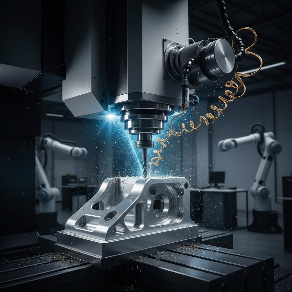
Xa se preguntou algúns vez como os enxeñeiros transforman un bloque sólido de aluminio nun soporte aeroespacial con forma precisa? Ou como os fabricantes de dispositivos médicos crean implantes cunhas tolerancias medidas en milesimas de polegada? A resposta atópase no corte personalizado de metal CNC: un proceso de fabricación que combina a precisión informática coa experiencia en traballo do metal para producir pezas adaptadas ás especificacións exactas.
CNC é a abreviatura de Control Numérico por Computador, referíndose ao uso de computadores para automatizar o control, a precisión e o movemento das ferramentas de máquina. Ao contrario dos métodos manuais de fabricación, nos que traballadores cualificados guían fisicamente as ferramentas de corte, a tecnoloxía CNC emprega instrucións programadas para dirixir cada movemento cunha precisión extraordinaria. Segundo Hmaking, este proceso utiliza equipos informatizados para guiar as ferramentas de mecanizado na transformación do metal dunha peza en bruto nun produto final mediante software CNC — esencialmente un programa composto por instrucións codificadas que garanten un movemento preciso, repetible e exacto.
Que fai especial o corte de metal CNC personalizado
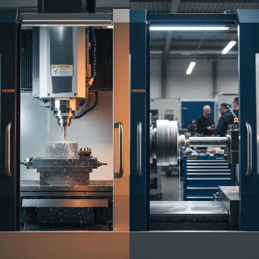
Entón, que é o que distingue o corte de metais CNC personalizado da maquinaria estándar? A diferenza radica na personalización en cada etapa da produción. A maquinaria estándar normalmente produce pezas predeterminadas empregando parámetros fixos e equipos CNC configurados para tarefas repetitivas. O traballo personalizado, porén, adapta todo o proceso ás necesidades únicas do seu proxecto.
Imaxine que precisa dun soporte de montaxe especializado con dimensións non estándar, fabricado nunha aleación específica de aluminio e con furos colocados con precisión a 0,375 polgadas de distancia. Un enfoque personalizado significa que o fabricante programa as trayectorias das ferramentas especificamente para a súa xeometría, selecciona ferramentas de corte optimizadas para o material da lámina metálica escollido e calibra a máquina para cumprir os seus requisitos exactos de tolerancia. Todas as decisións—desde as velocidades de avance ata os pasos finais de acabado—adáptanse especificamente á súa peza.
Esta natureza personalizada resulta especialmente valiosa cando se traballa con xeometrías únicas que non se axustan a plantillas estándar, con tolerancias estreitas requiridas para aplicacións críticas, con materiais especializados como o titano ou aliaxes exóticas e con pequenas series de produción nas que as ferramentas de produción en masa non son rentables.
Dende o deseño dixital ata a peza física
O percorrido desde o concepto ata o compoñente finalizado segue un fluxo de traballo definido que une o deseño dixital coa fabricación física mediante CNC. Comeza co deseño asistido por ordenador (CAD), onde os enxeñeiros crean un modelo 3D detallado que define as medidas e propiedades críticas da peza física. Este plano dixital captura todas as dimensións, ángulos e características que require a súa peza.
A continuación vén a fabricación asistida por ordenador (CAM), onde o software analiza o seu modelo 3D e xera as trayectorias das ferramentas —as rutas precisas que seguirán as ferramentas de corte. Como Tormach explica que o software CAM axuda a crear as traxectorias de ferramentas que seguirá a súa máquina, facendo esencialmente de ponte entre a fabricación dixital e a fabricación física. O programa CAM determina que ferramentas usar, en que orde e como deben moverse para eliminar material de forma eficiente acadando as tolerancias especificadas.
A tradución final realízase a través do código G, a linguaxe que entenden as máquinas CNC. Este conxunto de comandos e coordenadas move a máquina mentres xestiona elementos como cambios de ferramenta, refrigerante e velocidades do fuso. Algúns mecanicistas experimentados incluso escriben o código G manualmente, pero a maioría das fabricacións personalizadas de metal baséanse en instrucións xeradas por CAM para xeometrías complexas.
- Programación CAD/CAM: Ficheiros de deseño dixital traducidos a traxectorias de ferramenta lexibles pola máquina, específicas para a xeometría da súa peza
- Ferramentas específicas para o material: Ferramentas de corte, velocidades e avances optimizados para o seu metal escollido, xa sexa aluminio, acero ou aliñas especiais
- Especificacións de tolerancia: Requírense precisións definidas para cada característica, desde tolerancias de mecanizado estándar ata especificacións extremadamente rigorosas
- Requisitos de acabado: Especificacións de calidade superficial que van desde superficies mecanizadas até pulidas, anodizadas ou recubertas con pó de pintura
Comprender estes fundamentos permítelle comunicarse eficazmente cos fabricantes, especificar os seus requisitos con precisión e tomar decisións informadas sobre os seus proxectos de pezas metálicas personalizadas. Xa sexa que estea desenvolvendo prototipos ou planeando series limitadas de produción, este coñecemento forma a base para lograr resultados satisfactorios na fabricación de metais de precisión.
Procesos centrais de corte CNC e cando empregar cada un
Agora que entende como os deseños dixitais se converten en pezas físicas, xorde a seguinte pregunta: que proceso de corte dá forma realmente ao seu metal? Esta decisión afecta significativamente á calidade, custo e cronograma de produción da súa peza. Aínda que moitos fabricantes enumeran as súas capacidades, poucos explican cando cada proceso é realmente adecuado —e cando resulta insuficiente.
Catro métodos primarios de corte CNC dominan a fabricación precisa de metais: fresado, torneado, taladrado e fresado de contornos. Cada un emprega mecanismos distintos que o fan ideal para xeometrías e aplicacións específicas. Escoller o proceso incorrecto non só supón un desperdicio de diñeiro, senón que pode comprometer a precisión dimensional ou a calidade do acabado superficial que require a súa aplicación.
Explicación do fresado CNC
Imaxine unha fresa metálica rotatoria que se aproxima dunha peza fixa desde arriba, eliminando sistemáticamente material capa a capa. Ese é o fresado CNC en acción. A peza permanece inmóbil mentres a ferramenta de corte xira a alta velocidade, desprazándose ao longo de múltiples eixes (normalmente X, Y e Z) para tallar formas complexas.
Que fai tan versátil ao fresado? Segundo RapidDirect, o fresado realiza diversas operacións, como taladrado, ranurado, contorneado e acabado superficial, nunha única configuración. Esta capacidade multifuncional convérteo na opción preferida para pezas que requiren superficies planas, recortes, ranuras e contornos 3D intrincados.
Considere un bloque do motor coa súa complexa rede de pasaxes, superficies de montaxe e orificios de precisión. Ou un soporte aeroespacial con superficies inclinadas e bolsas para reducir o peso. Estas pezas mostran a forza da fresado: manexar xeometrías prismáticas que requiren precisión desde múltiples ángulos.
As operacións máis comúns de fresado inclúen:
- Fresado frontal: Crea superficies planas eliminando material da cara da peça de traballo
- Fresado de extremo: Talla ranuras, bolsas e perfís intrincados ao longo dos lados da fresa
- Fresado de perfil: Obtén formas complexas seguindo o contorno da peça de traballo
- Fresado de texto: Grava deseños detallados, logotipos ou marcas de identificación nas superficies
Non obstante, o fresado ten limitacións. Cando a peza require fundamentalmente características cilíndricas, a eliminación de metal cunha ferramenta mediante fresado resulta ineficiente en comparación co torneado. O proceso tamén xera custos máis altos de ferramentas e tempos de ciclo máis longos para certas xeometrías.
Cando escoller torneado fronte a fresado
O torneado inverte completamente o procedemento. En vez de rotar a ferramenta, a peza xira rapidamente mentres unha ferramenta estacionaria elimina material. Esta diferencia fundamental fai que o torneado sexa excepcionalmente eficiente para compoñentes redondos ou cilíndricos.
Imaxine a fabricación dunha árbore de precisión, unha fixación roscada ou unha vara de pistón hidráulico. Tal como explica Unionfab, o torneado CNC destaca na produción de pezas axialmente simétricas que requiren alta precisión e acabados superficiais excelentes. A rotación continua crea de forma natural superficies lisas en características cilíndricas, algo que o fresado ten dificultades en igualar.
As operacións de torneado CNC inclúen:
- Refrentado: Crea superficies planas nas extremidades da peza
- Rosca: Engade roscas internas ou externas con precisión
- Ranurado: Produce ranuras ou rebaixos para aneis en O e aneis de bloqueo
- Arandelado: Amplía furos existentes ou refina as dimensións internas
O compromiso? O torneado non pode producir de maneira eficiente superficies planas, características angulares ou xeometrías asimétricas. As pezas que requiren ranuras, bolsas ou contornos complexos necesitan fresado —ou unha combinación de ambos os procesos mediante máquinas de múltiples eixos.
Fresado CNC: Fabricación precisa de furos
Aínda que as fresadoras poden crear furos, o fresado CNC específico ofrece maior precisión e eficiencia para pezas con moitos furos. Consultar unha táboa de brocas ou unha táboa de tamaños de brocas garante a selección axeitada da ferramenta para os requisitos de diámetro da súa aplicación.
O fresado non é unha única operación —é, de feito, unha familia de procesos de fabricación de furos:
- Fresado estándar: Crea furos iniciais empregando brocas rotatorias —rápido e económico
- Arandelado: Aumenta e corrige a posición do furo despois de taladrar, mellorando a precisión cilíndrica
- Aguaceirado: O toque final: alisa os furos ás dimensións exactas con superficies internas como un espello
Ao revisar unha táboa de tamaños de brocas para o seu proxecto, lembre que o taladrado establece o furo inicial, o escariado corríxe a aliñación e o rebarbado alcanza a tolerancia final. Para aplicacións críticas —como asentos de rodamientos ou furos de pasador de precisión— estas tres operacións realízanse en secuencia.
Fresado CNC para chapas e metais máis brandos
As fresadoras CNC ocupan un nicho distinto, optimizadas para o corte rápido de materiais máis brandos e chapas. Aínda que estruturalmente son máis lixeiras que as fresadoras convencionais, as fresadoras CNC xiran as ferramentas a velocidades excepcionalmente altas — ideais para chapa de aluminio, lata e metais non ferrosos.
Os enrutadores destacan ao cortar formas perfiladas de pezas planas, crear sinais ou traballo en metal decorativo, e manexar producións de alta capacidade con xeometrías máis sinxelas. O seu menor custo e maiores velocidades fainos accesibles para moitos talleres.
As limitacións? Os enrutadores carecen de rigidez para cortar metais duros como o aceiro ou acadar as tolerancias máis estreitas. Os seus marcos máis lixeiros xeran máis vibración durante cortes agresivos, o que pode comprometer a precisión en aplicacións exigentes.
Táboa comparativa de procesos CNC
| Tipo de Proceso | Mellores aplicacións | Materiais Típicos | Tolerancias Alcanzables | Xeometrías ideais de pezas |
|---|---|---|---|---|
| Fresado por CNC | Blocos de motor, soportes, carcacas, cavidades de moldes | Aluminio, aceiro, aceiro inoxidable, titanio, latón, plásticos | ±0,001" a ±0,005" típico | Formas prismáticas, superficies planas, bolsos, ranuras, contornos 3D |
| Torsión CNC | Eixos, pernos, buxes, poleas, elementos de unión roscados | Aluminio, aceiro, latón, aceiro inoxidable, cobre | ±0,0005" a ±0,003" típico | Pezas cilíndricas, cónicas, simétricas respecto á rotación |
| Perforación CNC | Patróns de furados, círculos de parafusos, orificios de precisión | Todos os metais mecanizables | ±0,001" a ±0,005" (orificios escariados máis precisos) | Peza que require múltiples furados precisos |
| CNC routing | Perfís de chapa, sinais, paneis decorativos, xuntas | Aluminio, latón, cobre, plásticos, compósitos | ±0,005" a ±0,015" típico | perfís 2D, características 3D superficiais a partir de chapa |
Exemplos prácticos: Adecuación do proceso á peza
Aínda dubida sobre que proceso se axusta ao seu proxecto? Considere estes exemplos reais:
- Carcasa para implante médico: O fresado CNC trata a complexa xeometría externa, mentres que o torneado crea o furo interno—moitas veces completado nunha única máquina multi-eixe
- Eixe de transmisión automotriz: O torneado CNC produce o corpo do eixe; o fresado engade ranuras de chaveta ou superficies planas para a montaxe
- Envoltura electrónica: O fresado CNC perfila rapidamente paneis de lámina de aluminio; a perforación engade os furos de montaxe
- Colector hidráulico: A perforación de furos profundos crea os canais internos; o fresado maquina as bocas de conexión
Comprender estas distincións entre procesos permite comunicarse con precisión cos fabricantes, anticipar as implicacións de custo e garantir que as pezas personalizadas cheguen cumprindo todas as especificacións. Con esta base, está preparado para explorar outra decisión crítica: a selección do metal axeitado para a súa aplicación.
Guía de selección de metais para proxectos de CNC
Identificou o proceso de corte axeitado para a xeometría da súa peza—pero que metal debe entrar realmente na máquina? Esta decisión condiciona todo, desde os requisitos de ferramentas ata o rendemento final da peza. Escolla sabiamente, e o seu compoñente ofrecerá anos de servizo fiabilizado. Escolla mal, e encarará fallos prematuros, custos excesivos ou pezas que simplemente non funcionan como se pretende.
Ao contrario que na selección de procesos, a elección do material implica equilibrar múltiples factores contrapostos: resistencia mecánica, resistencia á corrosión, peso, mecanizabilidade e orzamento. De acordo con TrustBridge , a selección de materiais non debería basearse só nas propiedades mecánicas—o custo por unidade, a mecanizabilidade, o peso, a resistencia á corrosión e a conductividade térmica afectan todos a súa decisión.
Analicemos os metais máis comúns utilizados no corte metálico personalizado por CNC e exactamente cando cada un é adecuado para a súa aplicación.
Adequar os Materiais aos Requisitos da Aplicación
Cada metal aporta vantaxes distintas para aplicacións específicas. Comprender estas vantaxes axúdalle a conciliar as propiedades do material coas necesidades funcionais do seu proxecto.
Ligas de aluminio os metais de aluminio dominan a fresado CNC por boas razóns. Estes metais ofrecen unha relación resistencia-peso excesiva, protección natural contra a corrosión e un excelente fresado. Cando precisa compoñentes lixeiros que se corten rapidamente e de forma económica, a chapa de aluminio convértese na súa opción preferida.
Como apunta Hubs, as aleacións de aluminio teñen unha excelente relación resistencia-peso, alta condutividade térmica e eléctrica, e proteción natural contra a corrosión, polo que adoitan ser a opción máis económica tanto para prototipos como para pezas de produción.
As calidades máis comúns de aluminio inclúen:
- aluminio 6061: A calidade estándar: excelente fresabilidade, boa resistencia e ampla dispoñibilidade para aplicacións de uso xeral
- 7075 Aluminio: Resistencia de grao aeroespacial, próxima á de algúns aceros, pero cun custo superior
- aluminio 5083: Resistencia superior á auga salgada para usos mariños e de construción
Ligazóns de acero inoxidable entregan cando a resistencia, hixiene e resistencia á corrosión son máis importantes. Componentes de chapa de acero inoxidable aparecen en todo tipo de dispositivos médicos, equipos de procesamento de alimentos e sistemas de manexo de produtos químicos. Estas ligazóns combinar a alta ductilidade coa excelente resistencia ao desgaste.
O grao de acero inoxidable 316 merece atención especial. Con resistencia superior a solucións salinas e produtos químicos agresivos, é a opción preferida para ferraxes mariños, instrumentos cirúrxicos e equipos de procesamento farmacéutico. Aínda que é máis caro ca o acero inoxidable 304, a protección mellorada contra a corrosión xustifica o prezo maior en ambientes agresivos.
Acero de carbono ofrece a ruta máis rentable para compoñentes de alta resistencia. Cando a corrosión non é unha preocupación —ou cando os recubrimentos protexentes poden resolvela— a chapa de acero ao carbono ofrece excelentes propiedades mecánicas a un custo de material inferior. Os graos como o 1018 mecanízanse facilmente e soldanse de forma fiable, polo que resultan ideais para compoñentes estruturais, dispositivos de suxeición e maquinaria industrial.
Latón ofrece vantaxes únicas alén da súa atractiva aparencia dourada. A súa excelente condutividade eléctrica faino esencial para conectores eléctricos, mentres que as súas características de baixo froito son adecuadas para compoñentes de manexo de fluídos. Ao comparar latón e bronce para a súa aplicación, o latón ofrece xeralmente unha mecanización superior e un custo inferior, mentres que o bronce proporciona unha mellor resistencia ao desgaste en aplicacións de coxinetes.
Compromisos entre custo e rendemento
Isto é o que a maioría dos fabricantes non lle dirá: o custo do material representa só unha parte da súa despesa total por peza. A usinabilidade afecta dramaticamente o tempo de ciclo — e os materiais máis duros desgastan as ferramentas máis rapidamente, engadindo custos ocultos.
Considere isto: o latón úsase tan facilmente que os tempos de ciclo adoitan ser un 30-40 % máis rápidos que os de pezas equivalentes en acero. Esa velocidade de corte máis elevada compensa o custo máis alto do material bruto do latón para moitas aplicacións. Por outra banda, a resistencia excesiva do titán vai acompañada de velocidades de usinaxe lentas e desgaste rápido das ferramentas — chegando a duplicar ou triplicar o custo de usinaxe en comparación co aluminio.
| Material | Propiedades clave | Melhores industrias/aplicacións | Clasificación de Maquinabilidade | Custo relativo |
|---|---|---|---|---|
| Aluminio 6061 | Ligereiro, resistente á corrosión, excelente condutividade térmica | Aeroespacial, automoción, envolventes electrónicas, prototipado | Excelente | Baixo |
| Aluminio 7075 | Alta resistencia (comparable ao acero), boa resistencia á fatiga | Compontes estruturais aeroespaciais, aplicacións de alta tensión | Boa | Medio |
| aco Inox 304 | Boa resistencia á corrosión, alta resistencia, soldable | Procesamento de alimentos, arquitectura, industria xeral | Moderado | Medio |
| 316 Acero inoxidable | Resistencia superior a produtos químicos e solucións salinas, biocompatibilidade | Aplicacións mariñas, implantes médicos, equipamento farmacéutico | Moderado | Medio-Alto |
| azo 1018 de baixo contido en carbono | Boa resistencia, excelente soldabilidade, custo efectivo | Fixacións, pezas de máquinas, compoñentes estruturais | Boa | Baixo |
| aceriño aliado 4140 | Alta resistencia, resistente ao desgaste, tratábel termicamente | Engrenaxes, eixes, compoñentes industriais de alta tensión | Moderado | Medio |
| Latón C360 | Excelente condutividade, fricción reducida, aspecto decorativo | Conectores eléctricos, xuntas para fluídos, ferraxería decorativa | Excelente | Medio |
| Titanio Grao 5 | Resistencia excepcional en relación co peso, biocompatibilidade, resistencia á corrosión | Aeroespacial, implantes médicos, aplicacións militares | Pobre | Moi Alto |
Certificacións de material para industrias reguladas
Traballa nas áreas aeroespacial, médica ou de defensa? A trazabilidade do material convértese nun requisito ineludible. As industrias reguladas requiren informes de ensaio de fábrica certificados que documenten a composición química, as propiedades mecánicas e os rexistros do tratamento térmico.
Para aplicacións médicas que empreguen aceiro inoxidable 316 ou titano, verifique que os materiais cumpran as especificacións ASTM e que vengan acompañados de certificacións completas. Os compoñentes aeroespaciais adoitan requerir materiais procedentes de listas de fornecedores aprobados, con documentación completa da cadea de custodia. Discuta os requisitos de certificación ao comezo do seu proxecto: obter chapa de aluminio ou chapa de aceiro inoxidable certificada, con a documentación axeitada, pode alargar os prazos de entrega.
Comprender como a selección de materiais afecta o desgaste das ferramentas, o tempo de máquina e os requisitos de acabado permite tomar decisións informadas. Pero incluso a elección perfecta de material non significa nada sen especificacións adecuadas de tolerancia: este é o tema que exploraremos a continuación.
Especificacións de Tolerancia e Requisitos de Precisión
Escollaches o material perfecto para o teu proxecto personalizado de corte de metais por CNC, pero aquí é onde moitos enxeñeiros cometen erros. Especificar incorrectamente as tolerancias pode esgotar innecesariamente o teu orzamento ou provocar pezas que simplemente non se ensamblen. Comprender as especificacións de tolerancia transforma che dunha persoa que solicita presupostos nunha persoa que toma decisións informadas sobre fabricación.
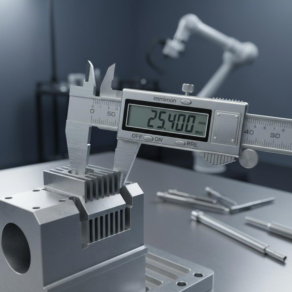
Que significa exactamente ±0,005 polgadas para a súa peza? Indica que a dimensión fabricada pode variar cinco milésimas de polgada por riba ou por baixo do tamaño nominal. Para un furado de 1,000 polgadas, os diámetros aceptables van desde 0,995 ata 1,005 polgadas. Esa franxa de tolerancia —o rango completo de dimensións permitidas— afecta directamente se a súa peza funciona como se pretende.
Segundo American Micro Industries, o mecanizado CNC alcanza tipicamente tolerancias de ±0,005 polgadas (0,127 mm) como punto de referencia estándar, mentres que as operacións de mecanizado de precisión poden acadar tolerancias máis estreitas de ±0,001 polgadas ou mellor cando as aplicacións requiren precisión excepcional. Esta distinción é importante porque tolerancias máis estreitas requiren equipos máis caros, velocidades de corte máis lentas e procesos adicionais de inspección.
Lectura e especificación de tolerancias
As especificacións de tolerancia aparecen en varios formatos estandarizados nos debuxos técnicos. Comprender estes formatos evita malas comunicacións que levan ao rexeitamento de pezas ou a reprocesos costosos.
As expresións de tolerancia máis comúns inclúen:
- Tolerancias bilaterais: ±0,005 polgadas—a dimensión pode variar igual por riba ou por baixo do valor nominal
- Tolerancias unilaterais: +0,002/-0,000 polgadas—permítese variación só nunha dirección
- Dimensións límite: 1,000/0,995 polgadas—especifica directamente os tamaños máximos e mínimos aceptables
A precisión decimal está directamente relacionada coa dificultade de fabricación. Como explica American Micro Industries, unha tolerancia de ±0,02 polgadas permite un rango dez veces máis largo que unha tolerancia de ±0,002 polgadas, afectando significativamente á complexidade e ao custo de produción. Cada cifra decimal adicional de precisión multiplica tipicamente o custo de mecanizado.
Ao revisar unha táboa de calibres de chapa metálica ou unha táboa de tamaños de calibre para o seu proxecto, teña en conta que os calibres estándar, como o grosor de acero de calibre 14 (aproximadamente 0,0747 polgadas) ou o grosor de acero de calibre 11 (aproximadamente 0,1196 polgadas), teñen as súas propias tolerancias inherentes. A chapa presenta lixeiras variacións respecto ao valor nominal, polo que as características mecanizadas deben ter en conta esta variación da materia prima base.
Comprensión dos fundamentos da GD&T
Atópase con símbolos nos planos que parecen xeroglíficos? Probablemente estea a ver a Dimensionado e Toleranciado Xeométrico—GD&T, polas súas siglas en inglés. Este sistema normalizado describe como deben encaixar e funcionar as pezas, indo máis aló das simples tolerancias dimensionais.
De acordo co Libro de receitas de CNC , a GD&T é un conxunto de símbolos e convencións normalizados que facilitan a comunicación exitosa entre clientes, fabricantes e participantes da cadea de suministro. O sistema non só aborda as variacións de tamaño, senón tamén as desviacións de forma, como a planicidade, a redondeza e a precisión de posición.
Conceptos clave de GD&T cos que te atoparás inclúen:
- Referencias: Puntos de referencia que establecen onde se orixinan as medicións — semellantes a definir o «Part Zero» nunha máquina CNC
- Marcos de control de características: Caixas que conteñen símbolos que definen as tolerancias xeométricas para características específicas
- Tolerancia de posición: Define ata que punto pode desviarse o centro dunha característica da súa localización verdadeira e prevista
- Tolerancias de forma: Controles como a planicidade, a cilindricidade e a rectitude que rexen a forma das características
Por que é importante o GD&T? Tal como explica o CNC Cookbook, este sistema expresa as tolerancias de maneira que, con frecuencia, resulta beneficiosa para o custo de fabricación. As tolerancias tradicionais de tipo «máis/menos» crean zonas de tolerancia cadradas, mentres que a tolerancia de posición do GD&T emprega zonas circulares — o que permite obter máis pezas aceptables co mesmo proceso de fabricación.
Cando importan as tolerancias máis estrictas
Non é necesario que cada característica da súa peza teña ultra precisión. Entender cando as tolerancias estreitas son realmente importantes — e cando supoñen un desperdicio de diñeiro — é o que distingue aos enxeñeiros experimentados dos novatos.
As tolerancias estreitas son esenciais para:
- Superficies de acoplamento: Pezas que deben encaixar con xogos específicos ou axustes por interferencia
- Asentamentos de rodamientos: Localizacións onde os veles interaccionan con rodamientos que requiren diámetros precisos
- Superficies de estanquidade: Áreas onde as xuntas tóricas ou empaquetaduras deben crear selos fiábeis
- Aliñamento do conxunto: Características que sitúan os compoñentes relativamente entre si
Polas contra, as características non críticas — superficies externas que non interaccionan con outras pezas, áreas cos éticas cubertas por carcacas ou dimensións con xogo xeneroso no montaxe — poden usar tolerancias estándar sen comprometer a funcionalidade.
De acordo co Básicos de GD&T se o seu produto final desexado non require valores de tolerancia elevados, como ±0,002 mm, os fresadores poden entregar a peza en menos tempo e cobrarlle considerablemente menos. A resistencia á tracción do seu material non cambia coas tolerancias máis estrictas, pero a súa factura, sen dúbida, sí.
Comparación das clases de tolerancia
| Rango de Tolerancia | Aplicacións Típicas | Impacto no custo | Equipamento necesario |
|---|---|---|---|
| ±0,015" a ±0,030" (Comercial) | Características non críticas, dimensións aproximadas, fabricación xeral | Baixa—aplicanse as tarifas estándar de mecanizado | Fresadoras e tornos CNC estándar |
| ±0.005" a ±0.010" (Precisión estándar) | A maioría das características funcionais, axustes típicos para montaxe, compoñentes mecánicos xerais | Moderada—representa a capacidade básica de mecanizado CNC | Equipamento CNC ben mantido con ferramentas adecuadas |
| ±0,001" a ±0,003" (Precisión) | Ajustes de roscas, montaxes de precisión, superficies de acoplamento críticas, compoñentes aeroespaciais | Alta—avances máis lentos, múltiples pasadas, inspección coidadosa | Máquinas CNC de precisión, ambientes con control climático, ferramentas calibradas |
| ±0,0005" ou máis estricto (Ultra-precisión) | Compóñentes ópticos, instrumentos de precisión, aeroespacial de alto rendemento, implantes médicos | Moi alta—procesos especializados, inspección extensiva | Rectificado, lapidado, máquinas especializadas de ultra-precisión, inspección de grao metroloxía |
O custo de especificar en exceso
Isto é o que moitos deseñadores pasan por alto: especificar ±0,001 polgadas cando ±0,005 polgadas funciona perfectamente supón un desperdicio significativo de diñeiro. As tolerancias máis estreitas requiren velocidades de corte máis lentas, pasos adicionais de acabado, cambios de ferramenta máis frecuentes e un tempo de inspección máis prolongado. Cada un destes factores incrementa o custo por peza.
O problema contrario —especificar tolerancias en defecto— xera problemas igualmente graves. As pezas que, tecnicamente, cumpren as especificacións laxas poden non montarse correctamente, provocando fallos dispendiosos no campo ou paradas da liña de produción. Como indica American Micro Industries, as pezas que superan os límites de tolerancia resultan inutilizables na maioría das aplicacións, o que se traduce nun aumento dos residuos e dos custos de produción.
A solución? Aplicar tolerancias estreitas só onde a función o exixe. Empregar tamaños de calibradores axeitados para o grosor do seu material, verificar os requisitos de tolerancia en función das necesidades reais de montaxe e comunicarse co seu fabricante sobre qué características requiren verdadeiramente precisión. Esta aproximación equilibrada ofrece pezas funcionais sen precisión excesiva que encareza innecesariamente o orzamento cando non aporta ningún beneficio.
Unha vez establecidos os fundamentos das tolerancias, está preparado para explorar outra decisión crítica: escoller entre fresado CNC e tecnoloxías alternativas de corte, como o corte por láser e o corte por chorro de auga, para a súa aplicación específica.
Comparación entre fresado CNC e corte por láser e por chorro de auga
Xa coñece as tolerancias e xa seleccionou o seu material, pero agora preséntase unha pregunta que sorprende a moitos enxeñeiros: debería a súa peza ser fresada mediante CNC, cortada con láser ou procesada mediante chorro de auga? Cada tecnoloxía sobresae en escenarios específicos, e escoller incorrectamente significa pagar máis por resultados inferiores.
Isto é o que a maioría dos fabricantes non lle dirá: ningún método de corte único funciona mellor para todas as aplicacións. Segundo SendCutSend , a selección do material, o tamaño, as tolerancias, as necesidades de posprocesado e moitos outros factores tómanse en conta ao escoller o mellor método de fabricación: onde un método de corte falla, outro ofrece unha solución.
Analicemos con precisión cando cada tecnoloxía resulta adecuada para o seu proxecto personalizado de corte de metais.
Mecanizado CNC fronte a corte por láser
Imaxine o fresado CNC e o corte de metais por láser como ferramentas complementarias e non como competidoras. Resolven problemas fundamentalmente distintos.
Fresado por CNC o mecanizado CNC elimina material mediante fresas rotatorias que entran en contacto físico coa peza de traballo. A fresa introdúcese na materia prima e desprázase ao longo de rutas programadas, creando características tridimensionais — bolsas, contornos, superficies inclinadas e xeometrías complexas imposibles de obter con procesos de corte bidimensionais.
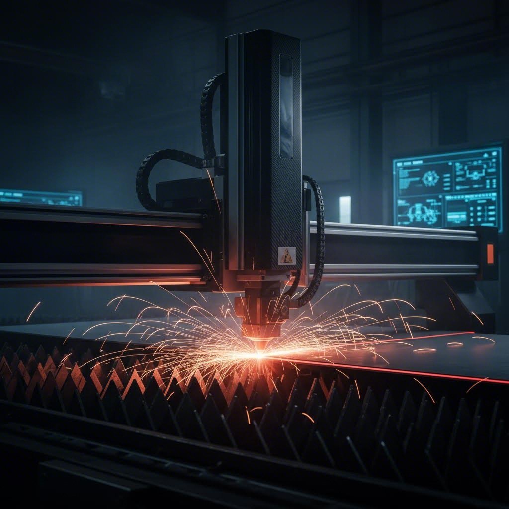
Un cortador láser, por contra, utiliza un feixe de luz enfocado para derretir, queimar ou vaporizar material ao longo dunha traxectoria plana de corte. Como explica SendCutSend, o corte láser é o proceso de usar un láser para facer cortes bidimensionais en material bruto — un feixe de luz moi fino e amplificado que derrete, quema e incluso vaporiza o material de traballo ao longo dunha traxectoria preprogramada.
Cando deberías buscar "corte láser preto de min" fronte a solicitar orzamentos de mecanizado CNC?
- Xeometría da peza: Necesitas un perfil plano cortado en chapa? O corte láser é mellor. Require características 3D, bolsos ou superficies mecanizadas? O fresado CNC é a túa resposta.
- Velocidade: A produción con corte láser é significativamente máis rápida — ata 2.500 polgadas por minuto para materiais finos. O fresado CNC é máis lento pero crea características que os láseres simplemente non poden.
- Calidade do Canto: O corte láser produce estrías lixeiramente ásperas en materiais máis groscios (por encima de 0,187 polgadas). O fresado CNC ofrece acabados superficiais consistentes independentemente da profundidade.
- Consideracións sobre o ancho de corte: O corte—o ancho de material eliminado durante o corte—afecta as características pequenas. Os láseres queiman material adicional, o que pode facer perder detalles intricados. As fresadoras CNC ofrecen unha eliminación de material previsible.
Aquí está a realidade práctica: se a súa peza comeza como unha chapa plana e permanece basicamente en 2D, o corte por láser ofrece velocidade e economía. No momento no que necesite furos roscados, profundidades variables, superficies mecanizadas ou xeometría complexa en 3D, o mecanizado CNC convértese en esencial.
Vantaxes do corte por láser
- Velocidades de corte extremadamente rápidas para perfís de chapa
- Excelente precisión con tolerancias estreitas en formas 2D
- O contacto mínimo co material reduce a complexidade do fixado
- Rentable para pezas planas de alto volume
Desvantaxes do corte por láser
- Limitado ao corte en 2D—non é posíbel facer características en 3D
- A zona afectada polo calor (HAZ) pode alterar as propiedades do material preto dos cortes
- As limitacións de grosor varían segundo o material e a potencia do láser
- Detalles pequenos e intrincados poden perderse na fenda de corte
Comprensión das vantaxes do corte por chorro de auga
Que ocorre cando o seu material non pode tolerar o calor? As aliaxes de titano, o aceiro revenido, os compoñentes tratados termicamente e os materiais compostos sofren cando se expoñen a procesos de corte térmicos. É aquí onde o corte por chorro de auga resplandece.
O corte por chorro de auga utiliza auga a presión extremadamente alta mesturada con partículas abrasivas de granate para erosionar o material ao longo das traxectorias programadas. Non se transfire calor á peza de traballo, eliminando por completo a zona afectada polo calor. Segundo SendCutSend, o corte por chorro de auga produce un acabado superficial de calidade extraordinaria na beira cortada, e, ao contrario do fresado CNC e do corte láser, elimina por completo as escorias e as rebabas.
Considere o corte por chorro de auga cando:
- Importa a sensibilidade ao calor: As normativas aeroespaciais prohiben frecuentemente por completo as zonas afectadas polo calor
- É necesario cortar material grosa: O corte por chorro de auga manexa grosores de material que supoñen un reto para os láseres
- É necesario procesar materiais compostos: Os materiais de fibra de carbono, G10 e fenólicos que se descolan co calor ou corte por fresado cortan limpiamente con chorro de auga
- O acabado superficial é crítico: A acción abrasiva produce bordos suaves sen necesidade de acabados secundarios
O compromiso? A velocidade. O corte por chorro de auga é significativamente máis lento que o corte láser ou por CNC. Para cantidades de produción de pezas máis sinxelas, esta diferenza de velocidade tradúcese directamente en custos máis altos por peza. Pero para aplicacións sensibles ao calor ou materiais difíciles, o chorro de auga segue sendo a única solución viable.
Corte por plasma: Cando ten sentido
Buscar "corte por plasma preto de min" indica normalmente proxectos que implican placas de acero máis grosas en volumes de produción. O corte por plasma utiliza gas ionizado para derreter metais condutores—principalmente acero ao carbono, acero inoxidable e aluminio en seccións máis grosas.
O plasma destaca en:
- Cortar placas de acero grosas (ata varias polegadas)
- Procesamento a alta velocidade de compoñentes de acero estrutural
- Produción rentable de pezas onde as tolerancias de precisión non son críticas
Non obstante, o plasma presenta limitacións significativas. A calidade da borda é inferior á do láser ou do chorro de auga, con superficies máis rugosas que requiren un acabado secundario para moitas aplicacións. As tolerancias son máis laxas—normalmente ±0,030 polgadas ou máis—o que fai que o plasma sexa inadecuado para montaxes de precisión. A zona afectada polo calor, considerable, tamén limita as súas aplicacións nas industrias sensibles ao calor.
Elixir a tecnoloxía de corte axeitada
Como navegar entre estas opcións? Comece con tres preguntas: Que xeometría require a súa peza? Que material está cortando? Que tolerancias debe acadar?
| Tecnoloxía | Rango de Grosor do Material | Calidade da beira | Zona afectada polo calor | Mellores Materiais | Tolerancias típicas | Velocidade Relativa |
|---|---|---|---|---|---|---|
| Fresado por CNC | Limitado pola envoltura da máquina—normalmente ata unha profundidade de 6" ou máis | Excelente—acabado superficial controlable | Mínimo con refrigerante adecuado | Todos os metais maquinables, plásticos e compósitos | ±0,001" a ±0,005" | Moderado—varía coa complexidade |
| CNC routing | Normalmente menos de 1" para metais | Bo—acabado superior en plásticos/compósitos | Baixo | Aluminio, lata, plásticos, madeira e compósitos | ±0.005" | Rápido para materiais en chapa |
| Cortar con láser | Ata 1" de aceiro; varía segundo o material/potencia | Bo a excelente—estrías no material máis grosso | Presente pero mínimo con equipos modernos | Acoiro, inoxidable, aluminio, latón, cobre | ±0.003" a ±0.005" | Moi rápido—ata 2.500 IPM |
| Corte por Xacto de Auga | Ata 8"+ dependendo do material | Excelente—bordos lisos sen rebarbas | Ningún—proceso de corte frío | Calquera material incluíndo compósitos, vidro, pedra | ±0,005" a ±0,009" | Lento—moi máis lento ca o corte láser |
| Corte por plasma | 1/8" a 6"+ para acero | Rústico—require un acabado secundario | Significativo | Metais condutores—acero, inoxidable, aluminio | ±0,020" a ±0,030" | Rápido para materiais grosos |
Estrutura de decisión para o seu proxecto
Use esta árbore de decisión práctica para identificar a súa tecnoloxía de corte óptima:
- Require a peza características en 3D, bolsos ou superficies mecanizadas? Se a resposta é afirmativa, é necesario o fresado CNC—o corte por láser e por axetauga producen só perfís en 2D.
- É a peza esencialmente un perfil plano obtido a partir dunha chapa? Se a resposta é afirmativa, considere o corte por láser pola súa velocidade e economía na maioría dos metais.
- Prohibe a súa aplicación calquera zona afectada polo calor? Se é así, o corte por chorro de auga convértese na súa opción principal para perfís 2D.
- Está cortando chapa de acero grosa onde a precisión non é crítica? Considere o corte por plasma para un procesamento rentable.
- Traballa con materiais compostos, plásticos ou metais máis brandos? O fresado CNC adoita ofrecer un acabado superficial superior a velocidades competitivas.
Lembrese: moitos proxectos benefíciase da combinación de tecnoloxías. Un fabricante podería cortar os seus perfís planos con láser e, a continuación, fresar as características críticas mediante CNC, conseguindo así velocidade e precisión onde cada unha resulta máis importante.
Comprender estes compromisos entre tecnoloxías ponno en condicións de solicitar os procesos apropiados e avaliar as ofertas de forma intelixente. Unha vez esclarecida a selección do método de corte, a seguinte consideración resulta igualmente importante: comprender que factores determinan os custos do corte personalizado de metais mediante CNC e como optimizar o seu orzamento sen renunciar á calidade.
Factores de custo e estratexias de optimización orzamentaria
Escollaches o teu proceso de corte, escolleches o material axeitado, especificaches as tolerancias e identificaches a tecnoloxía de corte óptima. Agora chega a pregunta que todo o mundo fai pero poucos fabricantes responden de forma transparente: ¿canto custará isto realmente?
Os prezos para o corte personalizado de metais mediante CNC adoitan sentirse como unha caixa negra. As ofertas chegan con cifras totais pero con pouca explicación do que fai subir eses números. Comprender a estrutura de custos permiteche tomar decisións de deseño que entreguen pezas de calidade sen gastos innecesarios — e axúdache a avaliar se as ofertas reflicten uns prezos de mercado xustos.
Que determina os prezos personalizados de CNC
Cada peza mecanizada personalizada ten custos derivados de seis factores principais. Segundo Komacut, a elección do material afecta de forma significativa tanto o custo como o proceso de mecanizado: materiais como o aceiro inoxidábel e o titano requiren máis tempo e ferramentas especializadas, aumentando así os custos, mentres que materiais máis brandos, como o aluminio, reducen tanto o tempo de mecanizado como o desgaste das ferramentas.
Aquí está como cada factor inflúe no seu beneficio neto:
- Material base: O stock real de metal do que se mecaniza a súa peza. Os custos dos materiais varían moito: o aluminio é considerablemente máis barato que o titánio, e as aleacións estándar son máis económicas que as calidades especiais. O volume tamén importa: os bloques máis grandes son máis caros, e os desperdicios de material afectan á súa utilización.
- Tempo de máquina: As fresadoras CNC facturan por hora, con tarifas que varían segundo o tipo de equipo. Segundo Komacut, a fresado de 3 eixes custa normalmente entre 35 e 50 $ por hora, mentres que as máquinas de 5 eixes cobran entre 75 e 120 $ por hora. As xeometrías complexas que requiren múltiples montaxes ou velocidades de avance máis lentas alargan os tempos de ciclo.
- Programación e configuración: Antes de comezar calquera corte, alguén debe programar as trayectorias das ferramentas e configurar a máquina. Estes custos fixos repártense entre a cantidade do seu pedido, polo que os prototipos únicos resultan desproporcionadamente máis caros que as series de produción.
- Desgaste das ferramentas: As ferramentas de corte non duran para sempre. Os materiais máis duros, como o acero inoxidable, desgastan as ferramentas máis rápido, aumentando os custos de substitución. As tolerancias estreitas que requiren ferramentas novas e afiadas tamén incrementan este custo.
- Operacións de acabado: Os tratamentos superficiais engaden custos segundo a súa complexidade. Un acabado tal como se mecanizou non ten custo adicional, mentres que as pezas de aluminio anodizado requiren procesamento secundario. Os acabados con recubrimento en pó, o granallado e o pulido engaden cada un custos laborais e de materiais.
- Inspección de Calidade: Cada peza require verificación. A inspección estándar engade un custo mínimo, pero as pezas de precisión que requiren medición CMM ou documentación exhaustiva aumentan significativamente o tempo de inspección.
Un factor frecuentemente pasado por alto? A urxencia do prazo de entrega. Os pedidos urxentes que requiren produción acelerada adoitan levar suplementos do 25-50% ou máis. Planificar con antelación aforra diñeiro real.
Estratexias para reducir os custos das pezas
Isto é o que saben os enxeñeiros experimentados: decisións de deseño intelixentes reducen os custos sen comprometer a función. Segundo Geomiq , reducir os custos de mecanizado CNC implica combinar a optimización do deseño, a selección coidadosa dos materiais e técnicas de fabricación eficientes—asegurando que o seu proxecto sexa rentable sen comprometer a calidade.
Considere estas estratexias probadas:
Simplifica o teu deseño
As características complexas que requiren ferramentas especializadas, múltiples montaxes ou programación intricada aumentan os custos. Como Factorem explica, a complexidade da peza inflúe nos custos mediante un maior tempo de mecanizado, ferramentas especializadas e dispositivos personalizados deseñados tendo en conta a xeometría do produto final. Antes de finalizar o seu deseño, pregúntese: ¿cada característica complexa desempeña unha función práctica?
Optimizar a utilización do material
O mecanizado CNC é un proceso subtrativo—o material eliminado convértese en desperdicio. Geomiq indica que, dependendo da complexidade da peza, esta técnica produce un desperdicio de material do 30 % ao 70 % do volume do bloque orixinal. Deseñar pezas que se integren de maneira eficiente dentro dos tamaños estándar de material reduce considerablemente os custos dos materiais.
Relaxar tolerancias non críticas
Especificar ±0,001 polgadas en todas partes cando só as superficies de acoplamento requiren esa precisión supón un desperdicio de diñeiro. As tolerancias estándar de ±0,005 polgadas satisfán a maioría das aplicacións e son máis rápidas de mecanizar. Reservar tolerancias estreitas para características nas que a función así o exixa.
Deseño para a Fabricación
Evite características que requiren ferramentas especializadas ou múltiples operacións de reposicionamento. Os cantos internos deben incluír radios que coincidan co tamaño estándar das fresas. Os grosores de parede deben manterse por encima das recomendacións mínimas para o seu material. Estes principios DFM reducen o tempo de ciclo e os custos de ferramentas.
Aproveitar Cantidades por Lote
Os custos de configuración permanecen fixos tanto se vostede encarga unha peza como cen. A análise de Geomiq amosa que encargar dez unidades en vez dunha pode reducir o custo por unidade nun 70%, mentres que os lotes de cen unidades alcanzan un aforro do 90% por peza. Se finalmente vai necesitar varias pezas, encargalas xuntas ten sentido económico.
Escolla Acabados Sabiamente
O acabado secundario engade custo. Un acabado anodizado en aluminio ofrece protección contra a corrosión e atractivo estético, pero só debe especificarse onde sexa necesario. As pezas ocultas no interior de conxuntos raramente requiren acabados premium. De maneira semellante, a soldadura de aluminio para conxuntos engade custo fronte aos deseños dunha soa peza cando a soldadura non é funcionalmente necesaria.
A redución máis eficaz de custos prodúcese ao principio do deseño. Comunicarse co seu fabricante durante o desenvolvemento—antes de finalizar os planos—revele a miúdo cambios sinxelos que reducen drasticamente os gastos de mecanizado mantendo toda a funcionalidade.
Unha vez compreendidos os factores de custo, está en condicións de tomar decisións informadas sobre o orzamento. A continuación, exploraremos as directrices de deseño que garanten que os seus ficheiros CAD se traduzan sen problemas en pezas fabricables, evitando revisións e atrasos onerosos.
Directrices de deseño para proxectos CNC exitosos
Calculou os custos e entende o que determina os prezos, pero aquí é onde moitos proxectos fallan incluso antes de comezar a mecanización. A mala preparación do deseño crea ciclos de revisión que atrasan a produción, incrementan os custos e frustran a todos os implicados. A boa nova? Seguir directrices de deseño probadas garante que o seu proxecto personalizado de corte de metal CNC pase da orzamento a pezas rematadas sen desvíos custosos.
Deseño para Fabricabilidade —en abreviatura DFM— aplica principios de enxeñaría que facilitan e reducen o custo de produción das pezas. De acordo con Modus Advanced , a implementación efectiva de DFM pode reducir os custos de fabricación entre un 15 e un 40 % e diminuír os prazos de entrega entre un 25 e un 60 % en comparación con deseños non optimizados. Eses aforros non son nin pequenos nin insignificantes. Representan a diferenza entre prototipos asequibles e proxectos que se saen de control respecto das estimacións iniciais.
Vamos a revisar os principios específicos de DFM que se aplican á fabricación de chapa metálica e ao traballo de CNC de precisión—xunto cos pasos de preparación de ficheiros que permiten obter unha oferta e producir o seu proxecto máis rapidamente.
Preparación dos seus ficheiros CAD para CNC
Antes de que o seu deseño poida converterse en pezas de fabricación metálica, debe traducirse a formatos que os equipos CNC poidan entender. Non todos os formatos de ficheiros CAD funcionan igual de ben, e presentar un formato incorrecto pode atrasar a súa oferta ou introducir erros durante a programación.
Como JLCCNC explica que a precisión comeza ao nivel do ficheiro: as máquinas CNC seguen as instrucións ata a fracción de milímetro, polo que, se os seus datos CAD están incompletos, no formato incorrecto ou son excesivamente complexos, poderá experimentar atrasos na produción e revisións onerosas.
Esto é o que debe saber sobre os formatos de ficheiro e os requisitos de envío:
- STEP (.stp, .step): O estándar universal para usinaxe CNC. Os ficheiros STEP preservan a xeometría 3D completa con total precisión entre distintos sistemas CAD. Cando teña dúbidas, exporte en formato STEP.
- IGES (.igs, .iges): Un formato máis antigo pero amplamente compatible, adecuado para a maioría das aplicacións personalizadas de fabricación de chapa metálica. Funciona ben, pero ocasionalmente pode perder algúns datos de superficie en xeometrías complexas.
- Parasolid (.x_t, .x_b): Excelente precisión para SolidWorks e sistemas compatibles. Preserva fielmente a xeometría detallada.
- Formatos CAD nativos: Ficheiros de SolidWorks, Inventor, Fusion 360 ou outras plataformas principais. Moitos fabricantes aceptan directamente os ficheiros nativos, o que preserva toda a intención do deseño.
- Evite STL e OBJ: Estes formatos baseados en malla son válidos para impresión 3D, pero descompoñen as curvas suaves en pequenos triángulos — inadecuados para traballar con CNC de precisión.
Ademais do formato do ficheiro, inclúa estes detalles esenciais coa súa entrega:
- Especificación do material co grao exacto da aleación
- Tolerancias críticas indicadas para as características que requiren precisión
- Requisitos de acabado superficial para cada superficie relevante
- Cantidade necesaria e prazo de entrega desexado
- Algún certificado requirido para industrias reguladas
Os envíos completos reciben orzamentos máis rápido. Os fabricantes non precisan responder por correo con preguntas aclaratorias, e os programadores poden comezar inmediatamente a xeración das traxectorias de ferramenta.
Principios críticos de DFM para o corte de metais por CNC
Certas decisións de deseño provocan problemas na fabricación que se traducen directamente en prazos máis longos e custos máis altos. Comprender estas limitacións antes de finalizar o seu deseño evita ciclos de revisión custosos.
Raios de esquina internos
Aquí hai unha realidade fundamental da mecanización por CNC: as fresas son redondas. Fisicamente, non poden crear esquinas internas afiadas de 90 graos. Segundo Modus Advanced, especificar o raio máis grande que o seu deseño pode admitir permite empregar ferramentas de corte máis grandes e ríxidas, que resisten mellor a flexión e proporcionan acabados superficiais superiores.
Directrices prácticas para esquinas internas:
- Raio mínimo: 0,005" (0,13 mm) — require ferramentas especializadas pequenas
- Radio recomendado: 0,030" (0,76 mm) ou maior—permite ferramentas estándar
- Bolsos profundos: Aumentar a 0,060" (1,52 mm) para reducir a flexión da ferramenta
As esquinas afiadas requiren ferramentas de pequeno diámetro especializadas que se flexionan baixo as forzas de corte, velocidades de avance lentas e múltiples pasadas de acabado. Engadir raios apropiados pode reducir o tempo de programación nun 50-100%.
Espeso mínimo da parede
As paredes finas vibran durante o mecanizado, provocando un mal acabado superficial e inexactitude dimensional. O tipo de material determina os mínimos seguros:
- Aluminio: mínimo 0,040" (1 mm); recoméndase 0,060"
- Aceros/Inoxidábeis: mínimo 0,050" (1,27 mm); recoméndase 0,080"
- Latón: mínimo 0,030" (0,76 mm); recoméndase 0,050"
Paredes máis finas ca estes mínimos poden requerir suxeición especial, velocidades de corte reducidas ou múltiples pasadas lixeiras—todo iso engade custo e tempo.
Relacións profundidade-diámetro en furados
Os buratos profundos e estreitos presentan retos significativos. As brocas estándar volvéñense inestables cando a profundidade supera catro veces o diámetro. Para operacións de dobrado de precisión ou características de montaxe que requiren buratos máis profundos, espere custos aumentados por ciclos de perforación intermitente ou equipos especializados para buratos profundos.
- Perforación estándar: profundidade ata 4× o diámetro
- Perforación profunda: 4-10× o diámetro require ciclos intermitentes
- Ultra profundo: além de 10× o diámetro necesita procesos especializados
Especificacións do filete
O xeito no que especifica as roscas afecta tanto á fabricabilidade como ao custo. Segundo Modus Advanced, as especificacións predeterminadas do software para buratos roscados adoitan crear restricións de fabricación innecesarias — os programas CAD adoitan usar por defecto especificacións de macho de corte mentres que os fabricantes poden preferir o roscado por deformación para mellorar a calidade da rosca.
Boa prácticas: especifique a clase de rosca (2B para roscas internas, 2A para roscas externas) en vez de indicar tamaños específicos de fresas. Isto permite aos fabricantes optimizar os seus procesos, garantindo ao mesmo tempo que se cumpren os seus requisitos funcionais.
Tamén considere con coidado a profundidade de roscado. Cada macho require unha entrada de rosca: os machos de fondo necesitan 1–2 filetes, os machos normais necesitan 3–5 filetes e os machos cónicos necesitan 7–10 filetes. Asegúrese de que a profundidade de taladrado exceda a profundidade de roscado nesta medida, ou especifique furos pasantes sempre que sexa posible.
Erros comúns de deseño que debes evitar
Máis aló das directrices dimensionais específicas, certas aproximacións de deseño causan de maneira consistente problemas na fabricación. Evitar estas trampas mantén o seu proxecto dentro do prazo e do orzamento.
Arestas afiadas
Cando dúas superficies se atopan en ángulos extremadamente agudos, a aresta afiada resultante é fráxil e problemática. Estas características descascarán durante o mecanizado, crean rebabas que requiren operacións secundarias e dananse facilmente durante a manipulación. A solución? Engadir pequenos chafláns exteriores cun radio de 0,005–0,015" para eliminar as arestas afiadas. Os fabricantes normalmente engaden estes chafláns durante a produción independentemente diso; especificalos desde o principio aforra tempo a todos.
Curvas complexas sen finalidade funcional
Curvas elaboradas e raios variables que parecen impresionantes no CAD xeran estrangulamentos significativos na fabricación. Modus Advanced observa que as curvas complexas poden aumentar o tempo de programación un 100–300 % e o tempo de mecanizado un 200–400 %. Antes de finalizar calquera característica curva, pregúntese: esta xeometría serve unha finalidade funcional específica, ou é puramente estética?
Características que requiren mecanizado de cinco eixes
As superficies en ángulo e os contornos compostos poden requerir equipos de cinco eixos—que custan un 300-600 % máis que as operacións de tres eixos. Sempre que sexa posible, aliñe as características cos planos X, Y e Z para permitir un mecanizado máis sinxelo. Se os ángulos complexos son realmente necesarios, comuniqueo canto antes para que os fabricantes poidan facer unha oferta axeitada.
Tolerancias excesivamente restrinxidas
Especificar tolerancias estreitas en todas as dimensións supón un desperdicio de cartos. Aplique requisitos de precisión só onde a función o exixe, e empregue tolerancias estándar no resto. Este principio esténdese tamén ao acabado superficial: non todas as superficies requiren o mesmo tratamento.
Opcións de acabado superficial e aplicacións
O acabado superficial afecta tanto á estética como á función. Segundo Fictiv, as características do acabado superficial son especialmente importantes se a súa peza entra en contacto con outros compoñentes: a rugosidade desempeña un papel clave na mecánica do contacto, xa que valores máis altos de rugosidade aumentan o froito e provocan un desgaste máis rápido.
Comprender as súas opcións axúdalle a especificar adequadamente:
Tal como se mecaniza
As pezas chegan directamente da fresadora CNC con marcas visibles das ferramentas. A rugosidade superficial mide normalmente entre 63 e 125 Ra (microinches). Este acabado é adecuado para compoñentes internos, prototipos e pezas que recibirán un acabado secundario. Prezo: nivel base — non se require ningún procesamento adicional.
Chorreado con bolas de vidro
Un medio a presión impacta na superficie, creando unha textura mate uniforme que oculta as marcas de maquinado. É excelente para pezas estéticas e como preparación previa a outros acabados. O granallado con bolas funciona na maioría dos metais e ofrece unha cobertura uniforme en xeometrías complexas, incluídos os ángulos e os redondeamentos.
Anodizado
Un proceso electroquímico que crea unha capa de óxido duradeira sobre o aluminio. A anodización mellora a resistencia á corrosión, proporciona illamento eléctrico e permite opcións de cor. A anodización tipo II engade un grosor de 0,0002–0,001" — fundamental ter en conta cando as tolerancias son estritas. A anodización tipo III (revestimento duro) ofrece unha resistencia ao desgaste aínda maior para aplicacións exigentes.
Recuberto en Polvo
A pintura en pó aplicada electrostáticamente e curada a alta temperatura crea recubricións grosas e duradeiras en case calquera cor. O recubrimento en pó é válido para o acero, o acero inoxidable e o aluminio. Teña en conta que este acabado engade un grosor considerable—normalmente entre 0,002 e 0,006"—polo que é necesario enmascarar características de precisión e furos roscados.
Gravado láser personalizado
Para identificación de pezas, logos ou serialización, o gravado láser proporciona marcas permanentes sen afectar á precisión dimensional. Esta técnica de fabricación láser é válida para practicamente calquera superficie metálica e pode combinarse con outros acabados.
Ao especificar acabados, lembre que diferentes superficies na mesma peza poden recibir tratamentos distintos. As superficies de axuste poderían quedar tal como saíron da máquina para manter a precisión dimensional, mentres que as superficies expostas recibirían anodizado para mellorar a estética e a protección.
Como a preparación axeitada acelera o seu proxecto
Seguir estas directrices de deseño e estes pasos de preparación de ficheiros ofrece beneficios tangibles máis aló das economías nos custos. Os fabricantes poden xerar orzamentos precisos máis rapidamente cando as presentacións están completas e os deseños seguen os principios de DFM (Deseño para a Fabricación). O tempo de programación redúcese cando as xeometrías son compatibles coa ferramenta estándar, en vez de requiriren solucións alternativas.
Quizais o máis importante, os deseños ben preparados minimizan os ciclos de revisión. Cada ronda de cambios no deseño engade días ou semanas ao seu cronograma. Facelo ben desde o principio —con radios adecuados, tolerancias razoables e ficheiros con formato apropiado— mantén o seu proxecto personalizado de corte de metal avanzando de forma constante, desde o concepto ata a entrega.
Unha vez dominada a preparación do deseño, está listo para avaliar posibles socios de fabricación. A seguinte sección explica qué certificacións son relevantes, qué preguntas debe formular aos fornecedores e como identificar fabricantes capaces de cumprir os seus requisitos específicos.
Elexir o Parceiro Adequado de Fabricación CNC Personalizada
Optimizaches o teu deseño, seleccionaches o material perfecto e especificaches as tolerancias apropiadas. Agora chega unha decisión que determina se o teu proxecto ten éxito ou fracasa: escoller o parceiro de fabricación axeitado. A calidade dos teus resultados finais de corte de metal personalizado mediante CNC depende totalmente das capacidades, experiencia e fiabilidade do taller que fabrica as túas pezas.
Esta é a realidade que moitos enxeñeiros descobren demasiado tarde: non todos os talleres de fabricación mediante CNC son iguais. Segundo WMTCNC , o fornecedor de CNC que selecciones desempeña un papel vital na túa cadea de valor — máis aló de simplemente fabricar pezas, inflúe na velocidade de lanzamento ao mercado, na fiabilidade do produto e na rendibilidade global. Unha mala elección pode provocar atrasos, problemas de calidade ou sobrecostes que danen a confianza dos clientes e a eficiencia interna.
Entón, como se distinguen os fabricantes de aceiro cualificados das talleres que terán dificultades coas súas necesidades? A resposta está na avaliación sistemática das certificacións, capacidades e prácticas de comunicación.
Certificacións importantes para o seu sector
As certificacións amosan se un fabricante opera con sistemas de calidade documentados ou simplemente o afirma. Para industrias reguladas, certas certificacións non son opcionais: son requisitos que debe cumprir a cadea de suministro.
ISO 9001 representa o nivel básico. Esta norma internacionalmente recoñecida indica que unha empresa mantén procesos estruturados de xestión da calidade con procedementos documentados, auditorías regulares e prácticas de mellora continua. Se un fornecedor potencial non ten ISO 9001, proceda con precaución, incluso para compoñentes non críticos.
IATF 16949 amplía a ISO 9001 con requisitos específicos do sector automobilístico. De acordo con Advisera a IATF 16949 engade moitos requisitos en torno ao deseño e control de procesos, competencia de persoas concretas, ferramentas estatísticas e análise dos sistemas de medición. Esta certificación demostra sistemas de calidade de grao automotriz capaces de cumprir os rigorosos requisitos da produción de chasis, suspensións e compoñentes estruturais.
Para aplicacións automotrices, a certificación IATF 16949 non é simplemente impresionante: con frecuencia é obrigatoria para os fornecedores de primeiro e segundo nivel. Fabricantes como Shaoyi (Ningbo) Tecnoloxía do metal mantén esta certificación especificamente porque os fabricantes de equipos orixinais (OEM) automotrices exixen sistemas de calidade documentados que van máis aló das normas ISO xerais.
AS9100D diríxese ás necesidades das industrias aeroespacial, espacial e de defensa. Esta norma centrase en problemas como a seguridade dos produtos, a xestión da configuración e a prevención de pezas falsificadas. Se os seus compoñentes van voar, a certificación AS9100D indica que o fabricante comprende a mentalidade de cero defectos que demandan as aplicacións aeroespaciais.
Ademais das certificacións de xestión da calidade, considere:
- NADCAP: Acreditación especial de proceso para tratamento térmico, procesamento químico e ensaios non destructivos
- Rexistro ITAR: Requírese para traballo relacionado coa defensa que implique datos técnicos suxeitos a control de exportación
- ISO 13485: Sistemas de xestión da calidade para dispositivos médicos
Ao avaliar fabricantes de pezas metálicas nas proximidades ou ao buscar talleres de fabricación nas proximidades, verifique sempre as certificacións directamente. Solicite copias das certificacións en vigor e confirme que o seu ámbito abarca os procesos que vostede necesita.
Avaliación das Capacidades do Fabricante
As certificacións confirmán a existencia de sistemas de calidade, pero son as capacidades as que determinan se un taller pode realmente fabricar as súas pezas. Segundo WMTCNC, avalie se o fornecedor emprega tornos CNC avanzados, fresadoras, rectificadoras e máquinas de medición por coordenadas (CMM), e verifique que o seu equipo técnico é competente no uso de ferramentas CAD/CAM e ten experiencia en usinaxe de múltiples eixes.
O equipamento é moi importante. Un taller que opere con máquinas de tres eixes antigas pode ter dificultades para fabricar xeometrías que as máquinas de cinco eixes manexan habitualmente. Pregunte sobre:
- Tipos de máquinas e capacidades dos eixes: Centros de maquinado de tres eixos, catro eixos ou cinco eixos
- Tamaños do envolvente: Dimensións máximas da peça que o equipo pode acomodar
- Nivel de automatización: Cargamento robótico, cambiadores de paletas e capacidades de fabricación sen operarios (lights-out)
- Equipamento de inspección: Máquinas de medición por coordenadas (CMM), comparadores ópticos e ferramentas de medición do acabado superficial
A experiencia co material é igualmente crítica. Non todas as talleres de fabricación en acero manexan competente o titánio ou as aleacións exóticas. Pregúntelles se traballan habitualmente co seu material específico e se coñecen as súas características de mecanizado. Os talleres con experiencia no seu tipo de material farán orzamentos máis precisos e obterán mellor resultados.
Unha capacidade a miúdo subestimada? A prototipaxe rápida e o soporte DFM. Os mellores socios de fabricación non só fabrican pezas, senón que axúdanche a deseñar pezas mellor. O soporte completo de DFM reduce os ciclos de revisión ao identificar problemas de fabricabilidade antes de comezar a produción. Busque fabricantes que ofreza capacidades de prototipaxe rápida, como un prazo de entrega de 5 días, que permitan ciclos de desenvolvemento de produtos máis rápidos sen comprometer a calidade.
Preguntas a Formular aos Proveedores Potenciais
Antes de comprometerse cun socio de fabricación, recolle a información que necesitas para tomar unha decisión informada. Segundo W.H. Bagshaw, a calidade do teu produto final depende da calidade das túas pezas mecanizadas con precisión, polo que non podes permitirte traballar con calquera fornecedor.
Fai estas preguntas esenciais cando avalíes calquera fornecedor potencial para o teu traballo metálico personalizado:
- Cales son os teus prazos habituais para pezas semellantes? Comprender os prazos estándar e se existen opcións aceleradas.
- Que cantidades mínimas de pedido requiren? Algúns talleres centranse nos volumes de produción, mentres que outros aceptan cantidades de prototipos.
- Ofrece servizos de prototipado? A prototipación rápida—idealmente en cinco días ou menos—permite a validación do deseño antes de comprometerse coas ferramentas de produción.
- Que operacións secundarias pode realizar internamente? Os talleres que realizan internamente os procesos de acabado, montaxe e inspección reducen a complexidade lóxica e os tempos de entrega.
- ¿Subcontrata algunha parte do proceso de mecanizado? A subcontratación engade tempo de entrega e pode provocar variabilidade na calidade.
- ¿Que documentación fornece? As certificacións de materiais, os informes de inspección e a documentación do primeiro artigo son importantes nas industrias reguladas.
- Cal é o prazo de resposta para os orzamentos? Os fabricantes que ofrecen respostas rápidas ás solicitudes de presuposto—como un prazo de resposta de 12 horas—demostran eficiencia operativa que normalmente se estende tamén á produción.
- ¿Ofrece programas de almacenamento de inventario? Para necesidades de produción continuada, as ordes globais e os programas Kanban reducen os custos por orde.
- Que formatos de ficheiros CAD aceptades? Confirme a compatibilidade co seu software de deseño.
- Pode fornecer referencias de proxectos semellantes? Falar con clientes existentes revela o rendemento no mundo real.
Avaliación da comunicación e da capacidade de resposta
As capacidades técnicas non significan nada se non pode comunicarse de forma eficaz co seu fornecedor. WMTCNC subliña a importancia de avaliar a capacidade dun fabricante para comprender os debuxos técnicos, ofrecer comentarios sobre a facilidade de fabricación (DFM) e suxerir alternativas de mecanizado; unha comunicación clara e áxil garante que non quedarán desatendidos cando xurxan problemas.
Preste atención durante as súas interaccións iniciais. O fornecedor fai preguntas aclaratorias que demostran que entende os seus requisitos? Ofrece comentarios ponderados sobre o seu deseño ou simplemente fai unha oferta pola información que lle enviou? Os mellores socios funcionan como extensións do seu equipo de enxeñaría.
O tempo de resposta importa durante toda a relación. Se obter un orzamento leva semanas, espera atrasos semellantes durante a produción. Os fabricantes que amosan capacidade de resposta rápida —como un prazo de 12 horas para orzamentos— adoitan manter esa rapididez cando necesites actualizacións de produción ou teñas preguntas sobre o teu pedido.
Verificación dos procesos de inspección de calidade
A inspección de calidade determina se as pezas cumplen realmente coas especificacións. WMTCNC recomenda preguntar sobre as ferramentas de inspección —calibres de espínula, micrómetros, máquinas de medición por coordenadas (CMM)— e solicitar mostras ou informes de inspección. A documentación axeitada de control de calidade é fundamental para industrias reguladas como aeroespacial ou automotriz.
As principais preguntas sobre calidade inclúen:
- Que equipos de inspección utiliza, e están calibrados regularmente?
- Realiza inspeccións durante o proceso ou só inspección final?
- Que documentación de inspección do primeiro artigo pode fornecer?
- Como xestiona as pezas non conformes?
- Cal é o seu procedemento de acción correctiva cando xorden problemas de calidade?
Para pezas personalizadas de acero inoxidable ou outros compoñentes de precisión, confirme que as capacidades de inspección do taller coinciden coas súas necesidades de tolerancia. Os talleres que afirmen ter capacidades de mecanizado de precisión deben dispor de máquinas de medición por coordenadas (CMM) e controles ambientais que apoiarán unha medición precisa.
Buscar fabricantes cualificados
Ao buscar talleres de fabricación metálica pequenos preto de min ou talleres de fabricación personalizada preto de min, considere ampliar a súa busca xeográfica. O mellor fabricante para o seu proxecto pode non ser o máis próximo. A loxística moderna fai que o envío sexa económico para a maioría das pezas, e as diferenzas de calidade entre talleres adoitan superar as lixeiras variacións nos custos de envío.
Os directorios en liña, as asociacións industriais e as recomendacións de colegas proporcionan puntos de partida. Non obstante, sempre verifique as capacidades mediante conversacións directas e, idealmente, visitas ás instalacións para programas de produción importantes.
WMTCNC suxire unha aproximación práctica de validación: comezar cun proxecto prototipo. É a forma máis rápida de verificar a verdadeira capacidade dun fornecedor, a súa disciplina nos procesos e a súa mentalidade de calidade antes de pasar á produción completa. Unha pequena encomenda inicial revela os patróns de comunicación, o rendemento real no tempo de entrega e a calidade das pezas sen arriscar un compromiso grande de produción.
Construír parcerías a longo prazo
O obxectivo non é atopar un fornecedor para unha única encomenda, senón identificar un socio fabricante que creza xunto cos seus requisitos. WMTCNC observa que un fornecedor fiable convértese nunha extensión a longo prazo do seu equipo, capaz de apoiar unha innovación acelerada e unha excelencia duradeira.
Busque fabricantes que invirtan na mellora continua, mantengan equipos modernos e demostren un interese auténtico polo éxito do seu proxecto. As mellores relacións desenvólvense cando ambas as partes se benefician da colaboración: vostede recibe pezas de calidade a tempo e eles obtén negocios fiábeis e continuados.
Cunsa os criterios de avaliación comprendidos e as preguntas preparadas, estás en condicións de escoller un socio fabricante con confianza. O paso final? Preparar o teu proxecto para a produción e pasar do concepto ás pezas rematadas—o que veremos na seguinte sección.
Dando os teus próximos pasos na fabricación personalizada de metais
Adquiriches unha formación exhaustiva en corte de metais personalizado por CNC—desde comprender os procesos fundamentais ata avaliar socios fabricantes. Agora é o momento de transformar ese coñecemento en acción. Sexa que esteas desenvolvendo un prototipo para validación ou planeando cantidades de produción, o camiño a seguir segue unha secuencia lóxica que garante o éxito.
Pense no seu proxecto como unha serie de decisións interconectadas, cada unha baseada na anterior. A selección do proceso depende da xeometría da súa peza. A elección do material alíñase cos requisitos da aplicación. As especificacións de tolerancia coinciden coas necesidades funcionais. E o seu socio de fabricación debe demostrar capacidades que apoiarán todos os requisitos que identificou.
Vamos sintetizar todo isto en pasos concretos que pode seguir de inmediato.
Lista de comprobación para o seu proxecto personalizado de CNC
Antes de solicitar orzamentos ou contactar con fabricantes, asegúrese de ter abordado cada elemento crítico. Esta preparación acelera considerablemente o proceso de orzamento e evita malentendidos custosos durante a produción.
- Finalice os seus ficheiros de deseño. Exporte modelos 3D listos para a produción en formatos STEP ou CAD nativos. Segundo MakerVerse , os proxectos con ficheiros completos obtéñense orzados e producidos máis rapidamente: cargue só a xeometría final sen ensamblaxes nin pezas de referencia, e utilice nomes de ficheiro claros e versionados, como «Bracket_7075_V3.step».
- Preparar a documentación de apoio. Crear debuxos técnicos 2D que especifiquen as dimensións clave, as tolerancias seguindo as normas ISO 2768 ou ASME Y14.5, as especificacións de roscas (por exemplo, M6 × 1) e os requisitos de acabado superficial. Incluír os números de revisión e as datas para garantir a rastreabilidade.
- Especificar o material e o grao da aleación. Non solicite simplemente «aluminio»: especifique 6061-T6, 7075-T651 ou a súa aleación exacta. Para pezas personalizadas de acero inoxidable, indique se necesita 304, 316L ou outro grao en función dos seus requisitos de resistencia á corrosión e resistencia mecánica.
- Definir os requisitos de acabado superficial. Determinar se cada superficie require un acabado «tal como se maquinou», granallado, anodizado ou recuberto con pólvora. Lembre que distintas superficies poden recibir acabados diferentes: especifique con precisión onde se aplica cada un.
- Establecer as especificacións de tolerancia. Aplique tolerancias estreitas só onde a función o exixa. Indique explicitamente as dimensións críticas nos seus debuxos técnicos, permitindo tolerancias estándar no resto para optimizar os custos.
- Determinar cantidade e cronograma de produción. As cantidades de prototipos, as primeiras series de produción e as necesidades continuas de volume afectan o prezo e o prazo de entrega. Comunica todos os teus requisitos, incluídos volumes futuros potenciais.
- Identificar os requisitos de certificación. Se o teu sector require documentación específica — informes de proba de laminación, inspección de primeira peza, conformidade coa IATF 16949 para automoción ou AS9100 para aeroespacial — especifícaos desde o inicio.
- Solicita orzamentos a fabricantes cualificados. Contacta con varios proveedores que amosen certificacións relevantes, capacidades adecuadas de equipos e coñecementos en materiais acordes ás túas necesidades do proxecto.
De acordo co FVMT , presentar solicitudes de orzamento con información faltante retarda o proceso de orzamentación ou leva a orzamentos inexactos. Usa esta lista de verificación para asegurarte de que cubrícheste todos os aspectos antes de contactar con posibles socios.
Pasando do concepto á produción
Coa súa documentación preparada, o camiño desde o concepto ata a fabricación das pezas acabadas convértese nun proceso sinxelo. Cada paso constrúese lóxicamente sobre o seu traballo de preparación.
Enviar solicitudes completas de presuposto
Envíe os seus ficheiros 3D, debuxos técnicos, especificacións de materiais e requisitos de cantidade xuntos. Canto máis completa sexa a súa solicitude, máis rápido recibirá un presuposto exacto. Os fabricantes que ofrecen unha resposta rápida ao presuposto — como unha resposta en 12 horas — demostran unha eficiencia operativa que normalmente se estende a toda a produción.
Avaliar criticamente os presupostos
Compare non só o prezo, senón tamén o prazo de entrega, as operacións de acabado incluídas, a documentación de inspección e os termos de envío. O presuposto máis baixo adoita excluir elementos que os competidores con prezos máis altos si inclúen. Asegúrese de comparar ámbitos equivalentes.
Validar cos prototipos
Para novos deseños, comece con cantidades de prototipo antes de comprometerse con volumes de produción. As capacidades de prototipado rápido —idealmente cun prazo de entrega de 5 días ou máis rápido— permiten a validación do deseño sen retrasos prolongados. Esta pequena inversión evita, con frecuencia, correccións dispendiosas durante a produción.
Aproveite o soporte DFM
Os mellores socios de fabricación revisan o seu deseño e suxiren melloras antes de que comece a produción. O soporte DFM integral identifica problemas de fabricabilidade, recomenda modificacións que reducen os custos e diminúe o número de ciclos de revisión. Esta aproximación colaborativa permite obter pezas melloradas máis rapidamente.
Confirme os requisitos de documentación
Antes de que comece a produción, confirme exactamente que documentación recibirá: certificados de material, informes de inspección dimensional, aprobación do primeiro artigo. Para traballos personalizados en metais en sectores regulados, os requisitos de documentación deben acordarse expresamente.
Planeaxe a escalabilidade
Se o seu prototipo ten éxito, necesitará cantidades de produción. Comente cedo as tarifas por volume, os programas de pedidos globais e as opcións de almacenamento de inventario. Os fabricantes preparados tanto para a prototipaxe como para a produción en masa simplifican esta transición.
Ponendo o seu coñecemento en acción
Agora posúe o coñecemento necesario para levar adiante proxectos personalizados de corte de metal con confianza. Entende que procesos de corte se adaptan a determinadas xeometrías, como afecta a selección do material ao rendemento e ao custo, por que é importante especificar correctamente as tolerancias, e que diferenzia aos fabricantes cualificados daqueles que terán dificultades coas súas requirimentos.
A industria de fabricación de metais premia aos clientes preparados. A documentación completa, as especificacións claras e as preguntas informadas sitúano como un cliente ao que os fabricantes queren atender ben. As súas pezas chegan máis rápido, cumpren consistentemente as especificacións e teñen un custo menor cando realizou o traballo de preparación previamente.
Para as necesidades de compoñentes automotrices e metálicos de precisión, os fabricantes que ofrecen servizos integrais—dende a prototipaxe rápida ata a produción masiva automatizada—racionalizan todo o proceso dende o deseño ata a entrega. Busque socios que mostren certificación IATF 16949, resposta rápida de orzamentos e verdadeira experiencia en DFM para optimizar os seus proxectos personalizados de corte metálico.
O seu seguinte paso? Tome ese ficheiro de deseño que levaba tempo desenvolvendo, prepare a documentación utilizando esta lista de verificación e solicite orzamentos a fabricantes cualificados. O camiño desde o concepto ata pezas listas para a produción é máis claro ca nunca—e está listo para percorrilo con confianza.
Preguntas frecuentes sobre o corte personalizado de metais CNC
1. Canto custa xeralmente o corte CNC?
Os custos personalizados de corte de metais CNC dependen de seis factores principais: tipo e volume de material bruto, tempo de máquina (fresado de 3 eixos custa entre 35 e 50 $/hora, mentres que o de 5 eixos custa entre 75 e 120 $/hora), custos de programación e configuración amortizados segundo a cantidade do seu pedido, taxas de desgaste das ferramentas en función da dureza do material, operacións de acabado como anodizado ou recubrimento en pó, e requisitos de inspección de calidade. As pezas sinxelas en pequenas series teñen un custo típico de 10 a 50 $ por peza, mentres que os compoñentes de precisión poden superar os 160 $ cada un. Pedir en lotes reduce considerablemente o custo por unidade: dez unidades en vez dunha poden reducir os custos ata un 70%. Fabricantes certificados IATF 16949, como Shaoyi Metal Technology, ofrecen resposta en 12 horas para axudarlle a entender rapidamente o prezo exacto.
2. Canto custa o corte de metal?
Os custos de corte de metal varían segundo o método de corte, o tipo de material e a súa grosor. O corte de chapa oscila entre 0,50 $ e 2 $ por polgada lineal ou entre 20 $ e 30 $ por hora, dependendo da técnica empregada. O corte por láser é especialmente adecuado para perfís de chapa fina, con velocidades de até 2.500 polgadas por minuto, polo que resulta económico para pezas en 2D. O corte por chorro de auga é máis caro debido ás súas menores velocidades, pero elimina as zonas afectadas polo calor en materiais sensibles. O fresado CNC permite traballar geometrías en 3D a velocidades moderadas, con excelente precisión. Para optimizar os custos, considere afrouxar as tolerancias non críticas, consolidar características e realizar pedidos por lotes, para así repartir os custos de preparación entre un maior número de pezas.
3. Canto custa a fabricación personalizada de chapa metálica?
A fabricación personalizada de chapa metálica ten un custo medio de 4–48 $ por pé cadrado, dependendo da selección do material, a complexidade e os requisitos de acabado. A chapa de aluminio é menos cara e máis rápida de mecanizar que a de acero inoxidable, que require ferramentas especializadas e velocidades de avance máis lentas. Os factores que afectan o custo total inclúen o grao do material (aluminio 6061 fronte a acero inoxidable 316), as especificacións de tolerancia (estándar ±0,005" fronte a precisión ±0,001"), os acabados superficiais (tal como se mecaniza, anodizado ou recuberto en pó) e a cantidade do pedido. Os fabricantes que ofrecen soporte integral de DFM (Diseño para a Fabricación) poden identificar optimizacións no deseño que reducen os custos entre un 15 % e un 40 % sen comprometer a calidade nin a funcionalidade.
4. Cal é a diferenza entre fresado CNC e corte por láser?
O fresado CNC utiliza fresas rotativas para eliminar material dunha peça de traballo, creando características tridimensionais como bolsas, contornos e superficies mecanizadas. O corte a láser emprega un feixe de luz focalizado para cortar perfís bidimensionais de láminas a velocidades extremadamente altas. Escolle o fresado CNC cando a túa peza require características tridimensionais, furos roscados, profundidades variables ou xeometrías complexas. Selecciona o corte a láser para perfís planos de material laminar cando a velocidade e a economía son os factores máis importantes. Moitos proxectos combinan ambas tecnoloxías: o corte a láser permite obter rapidamente os perfís, mentres que o fresado CNC realiza as características críticas onde a precisión é esencial.
5. Como elixir o socio adecuado en fabricación CNC?
Avalie os fabricantes potenciais en función das súas certificacións (ISO 9001 como mínimo, IATF 16949 para o sector automobilístico, AS9100 para o sector aeroespacial), das súas capacidades de equipamento (mecanizado de 3 eixos fronte a mecanizado de 5 eixos), da súa experiencia con aliaxes específicas e da súa resposta na comunicación. Pregunte polos prazos de entrega, cantidades mínimas por pedido, capacidades de prototipado, operacións secundarias ofrecidas e documentación fornecida. Busque socios que ofrezan prototipado rápido (entrega en 5 días), soporte integral de DFM (deseño para a fabricación) para reducir os ciclos de revisión e tempos de resposta rápidos para as cotizacións. Comezar cun pedido de prototipo permite validar o rendemento real dun fornecedor antes de comprometerse con volumes de produción.