 Kleine Chargen, hohe Standards. Unser Rapid-Prototyping-Dienst macht die Validierung schneller und einfacher —

CNC-Prototyping-Services enthüllt: Kostenintensive Fehler, die Ihren Zeitplan gefährden
Verständnis von CNC-Prototyping-Dienstleistungen und deren Zweck
Haben Sie sich schon einmal gefragt, wie ein digitales Design auf Ihrem Computerbildschirm zu einem greifbaren, testbaren und weiterentwickelbaren physischen Bauteil wird? Genau hier setzen CNC-Prototyping-Dienstleistungen an. Ob Sie eine neue Automobilkomponente entwickeln oder ein medizinisches Gerät verfeinern – das Verständnis dieses Prozesses kann den Unterschied zwischen einem erfolgreichen Markteintritt und kostspieligen Verzögerungen ausmachen.
CNC-Prototyping ist der Prozess, bei dem computergesteuerte numerisch gesteuerte Maschinen (CNC-Maschinen) verwendet werden, um Prototypenbauteile direkt aus digitalen CAD-Modellen herzustellen und so Konstruktionsentwürfe in funktionale, serienreife Komponenten für Tests und Validierung umzuwandeln – noch bevor die Massenfertigung beginnt.
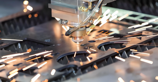
Im Gegensatz zum 3D-Druck oder manuellen Fertigungsverfahren, Nutzt CNC-Prototyping die subtraktive Fertigung —genaues Entfernen von Material aus massiven Blöcken aus Metall oder Kunststoff, um die gewünschte Geometrie zu erzeugen. Dieser Ansatz liefert gefertigte Teile mit denselben Materialeigenschaften und der gleichen Präzision wie Endprodukte in Serienfertigung.
Von der CAD-Datei zum physischen Bauteil
Stellen Sie sich CNC-Prototyping als Brücke vor, die Ihre digitalen Konzepte mit der greifbaren Realität verbindet. Die Reise beginnt damit, dass Ingenieure detaillierte 3D-CAD-Modelle erstellen, in denen Abmessungen, Toleranzen und Materialanforderungen festgelegt sind. Diese digitalen Dateien steuern anschließend hochpräzise CNC-Bearbeitungsmaschinen bei jedem Schnitt, jeder Bohrung und jeder Kontur.
Folgendes macht diese Umformung bemerkenswert:
- CAD-Software erfasst Ihre exakten Gestaltungsabsichten mithilfe geometrischer Bemaßung
- CAM-Programme übersetzen diese Konstruktionen in maschinenlesbare Anweisungen
- CNC-Maschinen führen Schnitte mit Toleranzen bis hin zu ±0,001 Zoll (0,025 mm) aus
- Das Ergebnis? Ein physisches CNC-Prototyp-Teil, das Ihre Produktionsvorstellung genau widerspiegelt
Dieser CNC-Fertigungsprozess erzeugt funktionale Muster, die Sie tatsächlich unter realen Bedingungen testen können – etwas, das Ersatzmaterialien einfach nicht leisten können.
Warum sich Prototypenherstellung von Serienfertigung unterscheidet
Stellen Sie sich den Unterschied zwischen einer Generalprobe und der Premiere vor. Die Prototypenherstellung dient als entscheidende Probe-Phase, in der Sie Probleme erkennen, solange sie noch kostengünstig zu beheben sind. Die Serienfertigung hingegen konzentriert sich auf Effizienz, Konsistenz und Volumen.
Die Unterschiede sind von erheblicher Bedeutung:
- Iterationsgeschwindigkeit: Prototypen stehen im Fokus einer schnellen Lieferzeit – oft innerhalb von 24 bis 72 Stunden – damit Sie schnell testen und optimieren können
- Designvalidierung: Sie prüfen, ob Ihr Konzept tatsächlich funktioniert, statt bewährte Designs in Serie zu fertigen
- Testzwecke: Prototypen unterziehen sich echten Leistungstests bezüglich Festigkeit, Passgenauigkeit und Funktionalität, bevor Sie in teure Werkzeuge investieren
- Kostenstruktur: Einzelne Prototypen können 500–2.500 USD kosten, während die Serienfertigung durch hohe Stückzahlen die Kosten pro Einheit deutlich senkt
Wenn Sie untersuchen, wofür Delrin bei Ihren Anforderungen an technische Kunststoffe geeignet ist, ermöglicht Ihnen beispielsweise das Prototyping, zu überprüfen, ob dieses Material wie erwartet funktioniert – bevor Sie Tausende von Dollar in Produktionsformen investieren.
Die Rolle der computergestützten numerischen Steuerung (CNC) in der modernen Entwicklung
Warum hat sich die computergestützte numerische Steuerung (CNC) zum Goldstandard für die Prototypentwicklung entwickelt? Die Antwort liegt in Präzision und Wiederholgenauigkeit. CNC-Maschinen folgen programmierten Anweisungen mit bemerkenswerter Konsistenz – das bedeutet, dass Sie zwei Prototypversionen herstellen können, bei denen ausschließlich Ihre gezielten Konstruktionsänderungen als Variable wirken – nicht jedoch Fertigungsabweichungen.
Moderne CNC-Prototypenfertigung bietet Vorteile, die traditionelle Verfahren nicht erreichen können:
- Materialauthentizität: Testen mit echten Serienwerkstoffen wie Aluminiumlegierungen, Edelstahl oder technischen Kunststoffen
- Dimensionsgenauigkeit: Erreichen von Toleranzen, die manuelle Bearbeitung nur schwer reproduzieren kann
- Schnelle Iteration: Ein Teil, das manuell mehrere Tage in Anspruch nehmen würde, kann über Nacht mittels CNC-Bearbeitung gefertigt werden
- Direkte Skalierbarkeit: Übergang vom Prototyp zur Serienfertigung ohne vollständige Neukonstruktion
Betrachten Sie dieses praktische Beispiel: Ein Hersteller von Unterhaltungselektronik stellte bei der Fertigung eines Prototyps fest, dass das Gehäusedesign elektromagnetische Störungen mit den internen Komponenten verursachte. Dieser 1.200-Dollar-CNC-Kunststoffprototyp enthüllte einen Fehler, dessen Behebung in der Serienfertigungs-Tooling 67.000 Dollar gekostet hätte.
Das Verständnis dieser Grundlagen bereitet Sie darauf vor, den gesamten CNC-Prototyping-Prozess zu durchlaufen – und teure Fehler zu vermeiden, die Zeitpläne gefährden. Wir erläutern nun Schritt für Schritt, wie dieser Prozess von der Einreichung des Konstruktionsdatensatzes bis zur endgültigen Auslieferung abläuft.
Der vollständige CNC-Prototypenfertigungs-Workflow im Überblick
Was passiert eigentlich, nachdem Sie auf „Senden“ klicken, um Ihre CAD-Datei zu übermitteln? Für viele Ingenieure und Produktentwickler wirkt der CNC-Prototyping-Prozess wie eine Black Box – Konstruktionsdaten gehen hinein, fertige Teile kommen heraus, doch der dazwischenliegende Ablauf bleibt rätselhaft. Das Verständnis jeder einzelnen Phase hilft Ihnen dabei, bessere Dateien vorzubereiten, effektiver zu kommunizieren und letztlich Ihre zerspant gefertigten Teile schneller zu erhalten.
Hier ist der vollständige Workflow von der ersten Einreichung bis zur endgültigen Lieferung:
- Einreichung der Konstruktionsdateien und erste Prüfung
- Konstruktion für die Fertigung (DFM) Analyse
- Materialauswahl und Beschaffung
- CAM-Programmierung und Maschineneinrichtung
- CNC-Bearbeitungsoperationen
- Qualitätsinspektion und -verifikation
- Nachbearbeitungsoperationen und endgültige Lieferung
Wir gehen gemeinsam durch, was Sie in jeder Phase erwarten können – und an welchen Kommunikationspunkten Ihre Zeitplanung Erfolg haben oder scheitern kann.
Einreichung und Prüfung der Konstruktionsdateien
Jeder Prototyp beginnt mit Ihrem digitalen Modell. Wenn Sie cAD-Dateien bei einer CNC-Fertigungswerkstatt in meiner Nähe oder bei einem Online-Dienst einreichen, prüft das technische Team die Konstruktionsunterlagen auf Vollständigkeit und Klarheit. Bei dieser ersten Prüfung werden Probleme erkannt, bevor sie zu kostspieligen Fehlern werden.
Während dieser Phase sind Rückfragen zu folgenden Punkten zu erwarten:
- Toleranzanforderungen – welche Abmessungen kritisch und welche allgemein sind
- Oberflächenfinish-Anforderungen für verschiedene Merkmale
- Materialspezifikationen und zulässige Alternativen
- Benötigte Menge und zeitliche Rahmenbedingungen
- Eventuelle besondere Anforderungen wie Zertifizierungen oder Prüfungen
Klare Konstruktionsdateien beschleunigen diese Phase erheblich. Fügen Sie vollständige 3D-Modelle (STEP- oder IGES-Formate sind universell geeignet), 2D-Zeichnungen mit hervorgehobenen kritischen Abmessungen sowie Anmerkungen zur Erläuterung der funktionalen Anforderungen bei. Je mehr Kontext Sie von Anfang an bereitstellen, desto weniger Rückfragen per E-Mail werden später erforderlich sein.
Die DFM-Prüfung folgt unmittelbar danach. Ingenieure analysieren, ob Ihr Konstruktionsentwurf effizient mittels CNC-Drehen, -Fräsen oder Mehrachsen-Bearbeitung hergestellt werden kann. Sie identifizieren potenzielle Probleme wie zu enge Toleranzen, eingeschränkte Werkzeugzugänglichkeit oder Merkmale, die spezielle Spannmittel erfordern würden.
Häufige DFM-Rückmeldungen umfassen:
- Inneneckradien, die für die verfügbare Werkzeugausführung zu klein sind
- Wandstärken, die während der CNC-Bearbeitung zu Vibrationen führen könnten
- Tiefe Aussparungen, die Werkzeuge mit verlängertem Reichweite erfordern
- Toleranzvorgaben, die strenger sind als funktional erforderlich
Dies ist Ihr erster wichtiger Kommunikationskontaktpunkt. Gute mechanische Fertigungsbetriebe in Ihrer Nähe geben Ihnen konkrete Empfehlungen – nicht nur Probleme, sondern auch Lösungen. Achten Sie hier besonders darauf; die Berücksichtigung von DFM-Feedback (Design for Manufacturability) vor Beginn der Bearbeitung verhindert Verzögerungen und senkt die Kosten.
Maschinenprogrammierung und -einrichtung
Sobald Ihr Design fertiggestellt ist, übersetzen CAM-Programmierer Ihr CAD-Modell in maschinenlesbaren G-Code. Diese Programmierung definiert jeden Fräs- bzw. Schnittweg, die Werkzeugauswahl, die Spindeldrehzahl und die Vorschubgeschwindigkeit, die die CNC-Maschine ausführen wird.
Der Programmieraufwand variiert stark je nach Geometrie Ihres Bauteils:
- Einfache prismatische Teile: Grundlegende 3-Achsen-Programmierung, innerhalb weniger Stunden abgeschlossen
- Komplexe gekrümmte Oberflächen: Mehrachsige Werkzeugwege, die eine sorgfältige Optimierung erfordern
- Funktionstolerante Merkmale: Zusätzliche Prüfpunkte und konservative Zerspanungsstrategien
Gleichzeitig bereiten die Maschinisten die physische Aufspannung vor. Dazu gehört die Auswahl geeigneter Spannmittel – Standard-Schraubstöcke für einfache Formen, maßgeschneiderte Weichspannfutter für unregelmäßige Geometrien oder Schwalbenschwanz-Aufspannungen für den Zugang bei 5-Achsen-Bearbeitung. Sie laden und messen die Schneidwerkzeuge, legen die Werkstückkoordinaten fest und überprüfen, ob alles korrekt ausgerichtet ist.
Bei CNC-gefertigten Teilen mit mehreren Bearbeitungsschritten wird die Aufspannplanung entscheidend. Ein Teil, das von sechs verschiedenen Seiten bearbeitet werden muss, erfordert eine sorgfältige Reihenfolge, um die Genauigkeit während des Wechsels zwischen den Spannvorrichtungen zu gewährleisten. Programmierer und Maschinist koordinieren sich, um den Handhabungsaufwand zu minimieren und gleichzeitig sicherzustellen, dass jedes Merkmal weiterhin zugänglich bleibt.
Qualitätsprüfung vor Auslieferung
Nach Abschluss der CNC-Zerspanungsoperationen durchläuft Ihr Prototyp die Qualitätsprüfung. In dieser Verifikationsphase wird bestätigt, dass das physische Teil innerhalb der vorgegebenen Toleranzen mit Ihrem digitalen Konstruktionsmodell übereinstimmt.
Die Prüfverfahren reichen von einfach bis hochsophistiziert:
- Manuelle Messung: Breitenmesser, Mikrometer und Höhenlehren für grundlegende Abmessungen
- Go/No-Go-Normale: Schnellüberprüfung von Bohrungen und Gewinden
- CMM-Inspektion: Koordinatenmessmaschinen für komplexe Geometrien und enge Toleranzen
- Messung der Oberflächenbehandlung: Profilometer zur Bestätigung, dass die Rauheitswerte (Ra) den Spezifikationen entsprechen
Was geschieht, wenn eine Messung außerhalb der Toleranz liegt? Hier zeigt sich der iterative Charakter des Prototyping-Prozesses. Statt Teile zu verschrotten und von vorne zu beginnen, können viele Probleme behoben werden – beispielsweise durch Entfernen zusätzlichen Materials, Nachbearbeitung von Oberflächen oder Anpassung von Merkmalen. Die Rückkopplungsschleife zwischen Prüfung und Bearbeitung ermöglicht eine Feinabstimmung ohne vollständigen Neustart.
Nach der Prüfung folgen die Endbearbeitungsschritte. Je nach Ihren Anforderungen können die Teile entgratet, oberflächenbehandelt, eloxiert, pulverbeschichtet oder mit anderen Komponenten montiert werden. Jeder Endbearbeitungsschritt erhöht die Fertigungszeit, ist jedoch möglicherweise unverzichtbar für eine präzise funktionale Erprobung.
Der letzte Kommunikationskontaktpunkt erfolgt vor dem Versand. Zu Ihren Teilen werden Qualitätsdokumente – Prüfberichte, Materialzertifikate, Fotos – geliefert. Prüfen Sie diese Dokumentation sorgfältig; sie bestätigt, was Sie erhalten, und liefert Referenzdaten für zukünftige Iterationen.
Das Verständnis dieses Arbeitsablaufs offenbart eine wichtige Erkenntnis: Das Prototyping ist kein linearer Prozess vom Entwurf bis zur Auslieferung. Vielmehr handelt es sich um einen iterativen Prozess, bei dem Feedback aus jeder Phase Anpassungen auslösen kann. Die erfolgreichsten Projekte berücksichtigen diese Realität und planen bereits im Vorfeld Zeit für mindestens eine Konstruktionsüberarbeitung ein. Nachdem Sie nun verstanden haben, wie Teile durch den Prozess laufen, sind Sie in der Lage, fundiertere Entscheidungen darüber zu treffen, welche Werkstoffe Sie spezifizieren möchten – eine Entscheidung, die die Leistungsfähigkeit Ihres Prototyps grundlegend prägt.
Leitfaden zur Werkstoffauswahl für CNC-Prototyping-Projekte
Hier ist eine Frage, die selbst erfahrene Ingenieure stolpern lässt: Spielt das Material Ihres Prototyps tatsächlich eine Rolle, wenn Sie lediglich Passform und Gestalt testen? Die kurze Antwort lautet: Ja – manchmal sogar entscheidend. falschen CNC-Bearbeitungsmaterialien kann Ihre Testergebnisse ungültig machen, wochenlange Entwicklungszeit verschwenden und zu Produktionsentscheidungen führen, die auf fehlerhaften Daten beruhen.
Die Werkstoffauswahl für Prototypen unterscheidet sich grundsätzlich von der Auswahl für Serienteile. Sie optimieren nicht nach Kosten pro Einheit bei großer Stückzahl, sondern nach Gültigkeit der Tests, Bearbeitungsgeschwindigkeit und der Fähigkeit, aus jeder Iteration schnell zu lernen. Im Folgenden gehen wir Ihre Optionen für Metalle und Kunststoffe durch und ordnen sie spezifischen Prüfanforderungen zu.
Metalle für funktionale Testprototypen
Wenn Ihr Prototyp reale Leistungsanforderungen unter Last, Temperaturbelastung oder mechanischem Verschleiß simulieren muss, bieten Metalle die erforderliche Genauigkeit. Jede Metallgruppe bringt dabei spezifische Vorteile für funktionale Testanwendungen mit sich.
Aluminiumlegierungen beherrschen die CNC-Prototypenerstellung aus gutem Grund. Sie sind leicht, hervorragend bearbeitbar und korrosionsbeständig – was sie ideal für Luftfahrtkomponenten, Automobilteile und Gehäuse für Unterhaltungselektronik macht. Aluminium 6061 lässt sich hervorragend bearbeiten und liefert ausgezeichnete Oberflächenqualitäten, während 7075 eine höhere Festigkeit für strukturelle Tests bietet. Am wichtigsten ist, dass Aluminium-Prototypen präzise vorhersagen können, wie sich serienmäßige Aluminiumteile im Einsatz verhalten werden.
Stahl und Edelstahl kommen ins Spiel, wenn Sie überlegene Festigkeit, Verschleißfestigkeit oder Leistung bei erhöhten Temperaturen benötigen. Edelstahl 304 eignet sich gut für Prototypen medizinischer Geräte, die Biokompatibilität erfordern, während 316 korrosiven Umgebungen standhält. Kohlenstoffstähle wie 1018 bieten kostengünstige Festigkeit für mechanische Tests. Der Nachteil? Stahl lässt sich langsamer bearbeiten als Aluminium, was die Lieferzeiten verlängert und die Kosten erhöht.
Titan wird für spezialisierte Anwendungen in der Luft- und Raumfahrt sowie bei medizinischen Implantaten eingesetzt, wo sein außergewöhnliches Verhältnis von Festigkeit zu Gewicht und seine Biokompatibilität die höheren Kosten rechtfertigen. Die Bearbeitung von Titan erfordert spezielle Werkzeuge und langsamere Schnittgeschwindigkeiten, weshalb längere Fertigungszeiten zu erwarten sind. Für Prototypen, die serienmäßige Titanbauteile exakt reproduzieren müssen, gibt es jedoch keinen Ersatz, der vergleichbare Ergebnisse liefert.
Bearbeitung von Bronze erweist sich als unverzichtbar für Laufflächen, Buchsen und Komponenten mit geringen Reibungseigenschaften. Bronze-Prototypen ermöglichen es Ihnen, Verschleifmuster und Reibungskoeffizienten zu validieren, die sich bei Ersatzwerkstoffen deutlich unterscheiden würden. Wenn Ihr Serienteil aus Bronze gefertigt wird, sollte dies auch für Ihren Prototyp gelten.
Konstruktionskunststoffe für schnelle Iteration
Kunststoff-Prototypen überzeugen, wenn Sie eine kurze Durchlaufzeit, Kosteneffizienz oder spezifische Eigenschaften wie Chemikalienbeständigkeit und elektrische Isolierung benötigen. Die Vielfalt an Konstruktionskunststoffen ermöglicht es Ihnen, nahezu jede funktionale Anforderung zu erfüllen – vorausgesetzt, Sie wählen den richtigen Werkstoff.
- Ich weiß. (Polyoxymethylen oder POM) zählt zu den beliebtesten Werkstoffen für präzises CNC-Prototyping. Dieses Delrin-Material bietet hervorragende Maßhaltigkeit, geringe Reibung und ausgezeichnete Zerspanbarkeit – wodurch glatte Oberflächen ohne umfangreiche Nachbearbeitung erzielt werden. Delrin-Kunststoff eignet sich hervorragend für Zahnräder, Lager und alle Komponenten, die engste Toleranzen sowie eine minimale Feuchtigkeitsaufnahme erfordern. Wenn Ingenieure die Frage stellen: „Wofür eignet sich Delrin am besten?“, lautet die Antwort nahezu alles, was Präzision und Verschleißfestigkeit erfordert.
Die Bearbeitung von Nylon birgt sowohl Chancen als auch Herausforderungen. Nylon für die spanende Bearbeitung zeichnet sich durch hervorragende Festigkeit, Zähigkeit und Verschleißfestigkeit aus und ist daher ideal für strukturelle Komponenten, Zahnräder und Gleitflächen. Allerdings nimmt Nylon Feuchtigkeit auf, was sich auf die Maßhaltigkeit und die mechanischen Eigenschaften auswirken kann. Für genaue Tests sollten Ihre Nylon-Prototypen entsprechend konditioniert oder feuchtigkeitsbeständige Sorten spezifiziert werden.
Polycarbonat PC zeichnet sich durch hohe Schlagzähigkeit und optische Klarheit aus. Wenn Ihr Prototyp Transparenz erfordert oder Sturztests überstehen muss, ist Polycarbonat die richtige Wahl. Es wird häufig für Schutzabdeckungen, Gehäuse medizinischer Geräte und alle Anwendungen eingesetzt, bei denen Sie die internen Komponenten sehen müssen. Eine sorgfältige Bearbeitung verhindert Rissbildung und erhält die Klarheit.
Acryl (PMMA) bietet hervorragende optische Eigenschaften zu geringeren Kosten als Polycarbonat, allerdings mit reduzierter Schlagzähigkeit. Für Prototypen, bei denen Ästhetik, Lichtdurchlässigkeit oder Witterungsbeständigkeit im Vordergrund stehen, lässt sich Acryl gut bearbeiten und bis zur Klarheit von Glas polieren. Beachten Sie jedoch: Bei der Bearbeitung bricht es leichter als Polycarbonat.
Abstimmung der Materialeigenschaften auf die Prüfanforderungen
Die entscheidende Frage lautet nicht, welches Material das „beste“ ist, sondern welches Material für Ihre konkrete Anwendung aussagekräftige Prüfergebnisse liefert. Berücksichtigen Sie dabei folgende Abstimmungsprinzipien:
- Funktionstest unter Last: Verwenden Sie dieselbe Werkstofffamilie wie bei der Serienfertigung. Ein Aluminium-Prototyp kann nicht vorhersagen, wie ein Stahl-Serienteil mechanischen Spannungen standhält.
- Passgenauigkeits- und Montageprüfung: Werkstoffsubstitution ist zulässig, wenn die Eigenschaften bezüglich der Wärmeausdehnung mit Ihrer Prüfumgebung übereinstimmen.
- Ästhetische Prototypen: Wählen Sie Werkstoffe, die Ihre gewünschte Oberflächenfinishverarbeitung zulassen – beispielsweise Eloxierung, Lackierung oder Polieren.
- Thermische Prüfung: Stellen Sie sicher, dass die Wärmeleitfähigkeit und die Wärmedurchbiegetemperatur mit denen der Serienwerkstoffe übereinstimmen.
- Prüfung bei chemischer Beanspruchung: Hier sind keine Substitutionen zulässig – es dürfen ausschließlich werkstoffgleiche Materialien wie bei der Serienfertigung verwendet werden.
| Materialtyp | Beste Anwendungen für das Prototyping | Bearbeitbarkeitsbewertung | Kostenerwägung | Eignung für Prüfungen |
|---|---|---|---|---|
| Aluminium 6061 | Luft- und Raumfahrt, Automobilbau, Gehäuse für Elektronik | Ausgezeichnet | Niedrig-Mittel | Funktionstests, Passgenauheitsprüfungen, thermische Prüfungen |
| Mit einem Gehalt an Stahl von mehr als 0,05 GHT | Medizinische Geräte, Lebensmittelverarbeitung, Marine | - Einigermaßen | Mittel-Hoch | Korrosionsprüfung, Biokompatibilität, Festigkeitsvalidierung |
| Titan | Luft- und Raumfahrt, medizinische Implantate, Hochleistungsanwendungen | Schwierig | Hoch | Kritisch, wenn Titan in der Produktion verwendet wird |
| Bronze | Lager, Buchsen, Verschleißteile | Gut | Mittel | Reibungs- und Verschleißprüfung |
| Delrin (POM) | Getriebe, Präzisionskomponenten, reibungsarme Teile | Ausgezeichnet | Niedrig | Maßgenauigkeit, mechanische Prüfung |
| Nylon | Strukturteile, Getriebe, Gleitflächen | Gut (feuchtigkeitsempfindlich) | Niedrig | Verschleißprüfung, Festigkeitsvalidierung |
| Polycarbonat | Schlagzähige Gehäuse, optische Komponenten | Gut (rissempfindlich) | Mittel | Schlagprüfung, Überprüfung der optischen Klarheit |
| Acryl | Anzeigekomponenten, Beleuchtung, Ästhetik | Gut (empfindlich) | Niedrig | Visuelle Prototypen, Lichtdurchlass-Tests |
Ein kostspieliger Fehler verdient besondere Aufmerksamkeit: die Verwendung von Prototypmaterialien, die nicht der Serienfertigungswirklichkeit entsprechen. Stellen Sie sich vor, Sie testen einen Kunststoffprototyp für ein Bauteil, das in der Serienfertigung aus Aluminium-Druckguss hergestellt wird. Ihre Passgenauigkeitsprüfungen könnten positiv ausfallen, doch die Wärmeausdehnung unter Betriebsbedingungen könnte zu Ausfällen führen, die Ihr Prototyp niemals vorhergesagt hätte. Die 800 US-Dollar, die Sie bei den Materialkosten eingespart haben, könnten 80.000 US-Dollar an Kosten für die Überarbeitung der Serienfertigungs-Werkzeuge verursachen.
Die Lektion? Passen Sie Ihre Materialauswahl an Ihre Testziele an. Für die Validierung von Form und Passgenauigkeit in frühen Entwicklungsphasen eignen sich kostengünstige Ersatzmaterialien durchaus. Sobald Sie jedoch Entscheidungen für die Serienfertigung treffen, sollten Sie in Prototypen investieren, die aus serienähnlichen Materialien hergestellt werden. Die dadurch erzielte Validierung schützt Ihre gesamte nachgeschaltete Investition. Nachdem die Grundsätze der Materialauswahl festgelegt sind, können Sie CNC-Prototyping mit alternativen Verfahren des Rapid Prototyping vergleichen – und verstehen, wann jeweils welcher Ansatz die besten Ergebnisse liefert.
CNC-Prototyping im Vergleich zu alternativen Verfahren des Rapid Prototyping
Sollten Sie Ihren Prototypen per CNC-Bearbeitung herstellen oder ihn mittels 3D-Druck fertigen? Diese Entscheidung bereitet Produktteams ständig Schwierigkeiten – und eine falsche Wahl kann wertvolle Entwicklungswochen verschwenden und Ihr Budget unnötig belasten. Tatsächlich zeichnet sich jedes Verfahren des Rapid Prototyping durch besondere Stärken in spezifischen Szenarien aus; das Verständnis dieser Unterschiede macht den entscheidenden Unterschied zwischen effizienter Entwicklung und teurem Versuch-und-Irrtum-Ansatz.
Vergleichen wir die CNC-Prototypenfertigung mit drei wichtigen Alternativen: dem 3D-Druck (additive Fertigung), dem Vakuumguss und dem schnellen Spritzguss.
Wann CNC-Bearbeitung dem additiven Fertigungsverfahren überlegen ist
der 3D-Druck erhält außerordentliche Aufmerksamkeit – und das zu Recht. Er ermöglicht komplexe Geometrien, die für CNC-Maschinen schwer herzustellen sind, erfordert nur einen minimalen Aufwand für die Einrichtung und ermöglicht schnelle Iterationen zur Validierung von Konzepten. Doch hier ist das, was der Hype oft verschleiert: Der 3D-Druck versagt häufig gerade dann, wenn Sie Ihren Prototypen am dringendsten benötigen.
Die prototypische Bearbeitung mittels CNC übertrifft die additive Fertigung in folgenden kritischen Szenarien:
- Funktionstests unter realen Lasten: CNC-gefertigte Teile aus massiven Aluminium- oder Stahlblöcken weisen mechanische Eigenschaften auf, die identisch mit denen der Serienteile sind. 3D-gedruckte Teile – selbst solche aus gesintertem Metall – weisen anisotrope Eigenschaften auf, die möglicherweise keine genaue Vorhersage der Leistung unter realen Bedingungen zulassen.
- Engen Toleranzanforderungen: CNC erreicht routinemäßig Toleranzen von ±0,001–0,002 Zoll (±0,025–0,05 mm). Die meisten 3D-Druckverfahren liefern Toleranzen von ±0,005–0,010 Zoll (±0,13–0,25 mm) – also fünf- bis zehnmal geringere Genauigkeit.
- Hervorragende Oberflächenqualität: CNC erzeugt direkt nach der Bearbeitung glatte Oberflächen, oft mit einer Rauheit Ra von 32–63 Mikrozoll, ohne Nachbearbeitung. Bei 3D-gedruckten Teilen sind Schichtlinien sichtbar, die umfangreiche Nachbearbeitung erfordern, um eine vergleichbare Qualität zu erreichen.
- Produktionsgleiche Werkstoffe: Wenn Ihr Serienteil aus Aluminiumlegierung 6061-T6 oder Edelstahl 303 besteht, erfolgt die CNC-Bearbeitung ausschließlich mit genau diesem Material. Beim 3D-Druck werden Ersatzmaterialien verwendet, die die Serienspezifikationen annähern – jedoch niemals exakt wiedergeben.
Betrachten Sie als praktisches Beispiel Titan-DMLS/CNC. Das Verfahren Direct Metal Laser Sintering (DMLS) kann Titanbauteile im 3D-Druckverfahren herstellen; die resultierenden Materialeigenschaften unterscheiden sich jedoch von denen von geschmiedetem Titan-Rundmaterial. Für Luftfahrtkomponenten, bei denen zertifizierte Materialeigenschaften erforderlich sind, liefert das schnelle CNC-Prototyping aus Stabmaterial die notwendige Validierung, die additive Fertigungsverfahren nicht leisten können.
Ebenso führt das Prototyping von Kohlefaserbauteilen durch CNC-Bearbeitung massiver Kohlefaserverbundplatten zu Bauteilen mit konsistenter und vorhersagbarer Faserausrichtung. Beim 3D-Druck mit gehacktem Kohlefaser-Filament entstehen Bauteile mit zufällig orientierten Fasern und deutlich geringerer Festigkeit.
Hybride Prototyping-Strategien
Folgendes wissen erfahrene Produktentwickler: Die beste Prototyping-Strategie besteht häufig nicht darin, sich für eine einzige Methode zu entscheiden, sondern darin, Methoden strategisch über den gesamten Entwicklungszeitraum hinweg zu kombinieren.
Ein hybrider Ansatz könnte wie folgt aussehen:
- Konzeptvalidierung (Woche 1–2): 3D-drucken Sie grobe Prototypen, um grundlegende Form, Ergonomie und Montagekonzepte zu testen. Hier steht Geschwindigkeit im Vordergrund; Präzision ist weniger wichtig.
- Designverfeinerung (Woche 3–4): Führen Sie 2–3 gedruckte Versionen durch, um die Passgenauigkeit mit zusammenzubauenden Komponenten zu prüfen und Nutzerfeedback einzuholen. Änderungen sind hier äußerst kostengünstig.
- Funktionsvalidierung (Woche 5–6): CNC-Maschinen-Prototypen aus produktionsäquivalenten Materialien. Testen Sie die mechanische Leistungsfähigkeit, validieren Sie Toleranzen und bestätigen Sie die Fertigbarkeit.
- Vorserien-Verifikation (ab Woche 7): Stellen Sie kleine Serien mittels Schnell-Spritzguss oder CNC-Fertigung in geringer Stückzahl her, um Ihren Produktionsprozess zu validieren.
Laut Branchenumfragen nutzen etwa 42 % der industriellen Prototyping-Unternehmen CNC für Funktionsprüfungen, während 38 % auf den 3D-Druck für die Design-Validierung setzen. Die erfolgreichsten Teams kombinieren beide Verfahren.
Das Vakuumgussverfahren kommt bei hybriden Strategien zum Einsatz, wenn Sie innerhalb kurzer Zeit 10 bis 100 Kunststoffteile benötigen. Erstellen Sie ein Mastermodell (häufig CNC-bearbeitet oder hochauflösend 3D-gedruckt) und fertigen Sie daraus Silikonformen für Polyurethan-Teile. Damit schließen Sie die Lücke zwischen Einzelprototypen und spritzgegossenen Serienteilen.
Entscheidungsrahmen für die Verfahrensauswahl
Hören Sie auf, zu raten, welches Prototyping-Verfahren das richtige ist. Beantworten Sie stattdessen diese fünf Fragen:
- Was testen Sie? Form und Ästhetik sprechen für den 3D-Druck. Funktion und Leistung erfordern die CNC-Bearbeitung.
- Welche Materialeigenschaften sind entscheidend? Wenn Ihr Test eine produktionsgleiche Festigkeit, thermisches Verhalten oder chemische Beständigkeit erfordert, wählen Sie CNC mit entsprechenden Materialien.
- Wie eng sind Ihre Toleranzen? Eine Präzision besser als ±0,005 Zoll erfordert in der Regel CNC. Bei weniger strengen Toleranzen stehen mehr Verfahren zur Auswahl.
- Wie viele Teile benötigen Sie? Ein bis fünf Teile – prüfen Sie alle Verfahren. Zehn bis fünfzig Teile – erwägen Sie das Vakuumgussverfahren. Ab fünfzig Teilen kann das schnelle Spritzgussverfahren kosteneffektiv sein.
- Was ist Ihre zeitliche Priorität? Das erste Teil innerhalb von 24–48 Stunden spricht für den 3D-Druck. Für die Validierung mit Produktionsqualität innerhalb einer Woche ist CNC die geeignetere Wahl.
| Methode | Materialgenauigkeit | Oberflächenfinish | Funktionale Prüfmöglichkeit | Lieferzeit | Kosten pro Bauteil (geringe Stückzahl) | Ideale Anwendungsfälle |
|---|---|---|---|---|---|---|
| CNC-Bearbeitung | Ausgezeichnet – materialgleich mit der Serienfertigung | Ausgezeichnet – typischer Rauheitswert Ra 32–63 μin | Ausgezeichnet – identisch mit der Serienfertigung | 2-7 Tage | $150-$2,500+ | Funktionale Prototypen, enge Toleranzen, Metallteile, Produktionsvalidierung |
| 3D-Druck (FDM/SLA) | Begrenzt – nur Ersatzkunststoffe | Mäßig – sichtbare Schichtlinien | Begrenzt – unterschiedliche Materialeigenschaften | 1-3 Tage | $20-$300 | Konzeptmodelle, Passprobe, komplexe Geometrien, schnelle Iteration |
| Metall-3D-Druck (DMLS/SLM) | Gut – aber anisotrope Eigenschaften | Mäßig – erfordert Nachbearbeitung | Mäßig – Materialeigenschaften unterscheiden sich von geschmiedetem Ausgangsmaterial | 3-10 Tage | $300-$3,000+ | Komplexe Metallgeometrien, Gitterstrukturen, unmachinierbare Formen |
| Vakuumguss | Mäßig – Polyurethan ähnelt Kunststoffen | Gut – repliziert das Mastermodell | Mittel—nützlich für Montage-Tests | 5-15 Tage | 50–200 USD (ab 20 Einheiten) | Kunststoffteile in geringer Stückzahl, Übergangs-Werkzeuge, Marketing-Muster |
| Schnelle Spritzgusstechnik | Ausgezeichnet—Produktionskunststoffe | Ausgezeichnet—Produktionsqualität | Ausgezeichnet—Validierung des Produktionsprozesses | 10-20 Tage | 15–75 USD (ab 100 Einheiten) | Produktionsvalidierung, Vorserienläufe, Prototypenfertigung in hoher Stückzahl |
Fazit? CNC-Prototyping ist nicht immer die richtige Wahl – doch fast immer die richtige Wahl für die funktionale Validierung vor der Serienfreigabe. Wenn Sie wissen müssen, wie sich Ihr Serienteil tatsächlich verhalten wird, liefern CNC-gefertigte Teile aus Serienwerkstoffen Antworten, die alternative Verfahren einfach nicht liefern können.
Nachdem Sie Ihre Prototyping-Methode ausgewählt haben, stellt sich die nächste entscheidende Frage: Wie optimieren Sie Ihr Design für eine schnellere und kostengünstigere Bearbeitung? Kleine geometrische Änderungen können sowohl Kosten als auch Lieferzeit erheblich senken – vorausgesetzt, Sie wissen, was Sie anpassen müssen.
Tipps zur Konstruktionsgestaltung für die Fertigung zur Beschleunigung der Prototypenerstellung
Hier ist ein frustrierendes Szenario: Sie haben Ihr CAD-Modell fertiggestellt, es zur Angebotserstellung eingereicht und erhalten Feedback, dass Ihr „einfaches“ Bauteil fünf Aufspannungen, spezielle Werkzeuge und eine Lieferzeit von zwei Wochen erfordert. Was ist passiert? Ihr Konstruktionsentwurf – obwohl funktional hervorragend – hat grundlegende Prinzipien der Fertigungsgerechtheit ignoriert, die bestimmen, wie schnell und kostengünstig CNC-Frästeile hergestellt werden können.
Die Konstruktionsgestaltung für die Fertigung (DFM) bei der Prototypenerstellung unterscheidet sich grundsätzlich von der DFM in der Serienfertigung. Bei der Serienfertigung optimieren Sie auf Effizienz im Volumen – also auf Minimierung der Kosten pro Einheit bei Tausenden von Teilen. Bei der Prototypenerstellung optimieren Sie hingegen auf Geschwindigkeit und Erkenntnisgewinn. Eine einzige DFM-Anpassung kann die Bearbeitungszeit um 30–50 % reduzieren. Das ist der Unterschied zwischen dem Erhalt maßgefertigter Frästeile innerhalb von drei Tagen oder zehn Tagen.
Geometrieoptimierung für schnellere Bearbeitung
Jedes geometrische Merkmal, das Sie hinzufügen, bedeutet Bearbeitungszeit – und potenzielle Komplikationen. Intelligente Geometrieentscheidungen beschleunigen Ihre CNC-gefrästen Prototypen, ohne die Funktionalität einzuschränken.
Richtwerte für Wandstärken:
- Mindestwandstärke für Metall: 0,8 mm (0,031 Zoll). Dünnere Wände führen zu Vibrationen, Verformungen und möglichen Werkzeugbrüchen – insbesondere bei Aluminium 7075
- Mindestwandstärke für Kunststoff: 1,2 mm (0,047 Zoll). Spröde Kunststoffe wie Acryl erfordern noch größere Wandstärken
- Halten Sie die Wandstärke möglichst einheitlich. Ungleichmäßige Wände verursachen Verzug, insbesondere bei Kunststoffen während und nach der Bearbeitung
Anforderungen an innenliegende Ecken:
- CNC-Werkzeuge sind rund – sie können physisch keine scharfen 90°-Innenecken fräsen
- Kleinster gängiger Werkzeugdurchmesser: 1 mm (mindestens R0,5-Ausrundung)
- Tiefere Aussparungen erfordern größere Ausrundungen zur Gewährleistung der Werkzeugsteifigkeit. Faustregel: Je tiefer die Aussparung, desto größer die erforderliche Ausrundung
- Gestalten Sie innenliegende Ausrundungen so, dass sie gängigen Werkzeuggrößen entsprechen (R0,5, R1,0, R1,5, R2,0, R3,0 mm), um Sonderwerkzeuge zu vermeiden
Bohrungs- und Merkmalsbeschränkungen:
- Mindestempfohlener Bohrungsdurchmesser: 1 mm (0,039 Zoll), sofern Mikrobohren akzeptabel ist
- Die Bohrtiefe sollte bei Standardbohrungen 6× den Durchmesser nicht überschreiten. Tiefere Bohrungen erfordern spezielle Werkzeuge und langsamere Vorschübe
- Wandeln Sie Sacklocher in Durchgangslöcher um, wenn dies funktional zulässig ist – dies verbessert die Spanabfuhr und senkt die Kosten
- Standard-Bohrungsdurchmesser können schneller bearbeitet werden als Sondermaße. Verwenden Sie nach Möglichkeit Bohrgrößen gemäß der Bohrtabelle
Fragen Sie sich, welche Toleranz für Gewindebohrungen gilt? Standard-Gewindebohrungen folgen bestimmten Verhältnissen von Tiefe zu Durchmesser. Für die meisten Anwendungen bietet eine Gewindeeintauchtiefe von 1,5× dem Nenndurchmesser volle Festigkeit. Tiefere Gewinde bringen selten zusätzlichen Nutzen, erhöhen jedoch stets die Bearbeitungszeit.
Toleranzspezifikationen, die für Prototypen relevant sind
Übergenaue Toleranzen sind der stille Killer von Prototyp-Zeitplänen. Wenn jede Abmessung ±0,01 mm aufweist, haben Sie die Fräs-Kosten bereits um das 2- bis 5-Fache erhöht – ohne funktionellen Nutzen. DFM speziell für Prototypen bedeutet, enge Toleranzen ausschließlich dort anzuwenden, wo sie tatsächlich erforderlich sind.
Praktische Toleranzrichtlinien:
- Nicht-kritische Abmessungen: ±0,1 mm (±0,004 Zoll). Diese sind mit Standard-CNC-Bearbeitungsschritten erreichbar und erfordern nur eine minimale Verifizierung.
- Pass- und Montageabmessungen: ±0,05 mm (±0,002 Zoll). Dies ist für Fügeflächen ohne besondere Verfahren durchaus angemessen.
- Kritische Funktionsabmessungen: ±0,01 mm (±0,0005 Zoll). Diese sind ausschließlich für Lagerpassungen, Dichtflächen und hochpräzise Schnittstellen vorzusehen.
- Allgemeine Regel: Enge Toleranzen dürfen bei weniger als 10 % Ihrer Abmessungen angewendet werden.
Oberflächengütespezifikationen:
- Standard-Oberflächenteile: Ra 1,6–3,2 µm – direkt aus CNC-Bearbeitung ohne Nachbearbeitung erzielbar.
- Gleit- oder Dichtflächen: Ra 0,8 µm oder besser – erfordert Nachbearbeitungsschritte und verlängert die Bearbeitungszeit.
- Kunststoffe mit hoher optischer Klarheit (PMMA, PC): erfordern eine Hochgeschwindigkeits-Finishbearbeitung mit geringen Zustellwerten sowie gegebenenfalls eine manuelle Polierung
Stellen Sie sich selbst die Frage: Wird diese Toleranz tatsächlich während der Prüfung überprüft? Falls nicht, beschleunigt deren Lockerung die Fertigung, ohne die Funktionalität Ihres Prototyps zu beeinträchtigen.
Häufig vorkommende Konstruktionsmerkmale, die die Produktion verlangsamen
Bestimmte Konstruktionsentscheidungen – oft getroffen, ohne die Auswirkungen auf die Fertigung zu berücksichtigen – führen zu unverhältnismäßig langen Verzögerungen. Das Erkennen dieser Muster hilft Ihnen dabei, CNC-gefräste Teile so zu konstruieren, dass sie effizient bearbeitet werden können.
Merkmale, die den Zeitplan verlängern:
- Tiefe, schmale Nuten: Erfordern Werkzeuge mit verlängerter Reichweite, langsamere Vorschübe und mehrere Bearbeitungsgänge. Falls möglich, sollten Nuten verbreitert oder ihre Tiefe reduziert werden.
- Merkmale an mehreren Flächen: Jeder zusätzliche Aufspannvorgang erhöht den Zeitaufwand für das Neupositionieren, die erneute Fixierung und die Überprüfung. Konstruieren Sie kritische Merkmale so, dass sie von möglichst wenigen Seiten aus zugänglich sind.
- Dünne, nicht gestützte Abschnitte: Vibrationen während der Bearbeitung, was reduzierte Vorschübe und erhöhte Bearbeitungsdurchgänge erfordert. Temporäre Stützstrukturen hinzufügen oder Konstruktion überarbeiten
- Texte und feine Gravuren: Erfordern kleine Werkzeuge, langsame Drehzahlen und sorgfältige Programmierung. Optische Details auf spätere Iterationen verschieben
- Komplexe gekrümmte Oberflächen: Erfordern eine 5-Achsen-Bearbeitung oder mehrere Aufspannungen. Kurven dort vereinfachen, wo dies funktional zulässig ist
Strategien zur Reduzierung der Aufspannungen:
- Kritische Merkmale nach Möglichkeit auf denselben Flächen zusammenfassen
- Nicht sichtbare Referenzflächen oder Spannbereiche hinzufügen, um die Stabilität der Aufspannung zu verbessern
- Erwägen Sie, komplexe Einzelteile in einfachere Baugruppen aufzuteilen – bei einer tiefen Roboter-Gehäusekonstruktion wurde durch die Neugestaltung als zwei Teile die Kosten um 40 % gesenkt und die Lieferzeit halbiert
Grundlagen der Dateivorbereitung:
- Wasserdichte Volumenmodelle ohne fehlende Flächen bereitstellen
- Saubere STEP-Dateien mit korrekter Referenzgeometrie exportieren
- Fügen Sie 2D-Zeichnungen bei, die ausschließlich kritische Toleranzen angeben – Standardmaße bleiben mit der allgemeinen Toleranz versehen.
- Geben Sie die Standard-Toleranznormen an (z. B. ISO 2768-m oder äquivalent), anstatt jede einzelne Merkmalsangabe zu tolerieren.
Mehr als 70 % der Bearbeitungsfehler gehen auf unvollständige oder unklare Zeichnungen zurück. Fünfzehn Minuten Aufwand für eine sorgfältige Dateivorbereitung können Tage an Rückfragen und Klärungsrunden einsparen.
Der grundlegende Unterschied zwischen DFM für Prototypen und DFM für Serienfertigung liegt in den Prioritäten. Bei der Serienfertigung steht die Optimierung der Einzelteil-Kosten über Tausende von Teilen im Vordergrund – dies rechtfertigt teure Spannvorrichtungen, spezielle Werkzeuge und aufwändige Einrichtungen, deren Amortisation sich durch die große Stückzahl lohnt. Bei der Prototypenerstellung steht hingegen die Zykluszeit und die Geschwindigkeit des Lernprozesses im Vordergrund. Akzeptieren Sie daher geringfügig höhere Kosten pro Einzelteil, um schnellere Iterationsschleifen zu ermöglichen. Dieser Kompromiss führt nahezu immer zu besseren Projektergebnissen.
Mit Ihrem Design, das für eine effiziente Bearbeitung optimiert ist, wird das Verständnis dafür, wie verschiedene Branchen diese Prinzipien anwenden – und welche Zertifizierungen sie verlangen – zu Ihrem nächsten Vorteil.
Branchenanwendungen und Zertifizierungsanforderungen
Erfordert Ihre Branche tatsächlich zertifizierte CNC-Prototypenfertigungsdienstleistungen, oder dient die Zertifizierung lediglich als formale Pflichtübung? Die Antwort hängt vollständig vom Sektor ab, den Sie bedienen – und ein falsches Verständnis hierzu kann entweder zu unnötigen Kosten durch überflüssige Konformitätsmaßnahmen führen oder Ihr Projekt kostspieligen regulatorischen Rückschlägen aussetzen. Klären wir die Verwirrung und prüfen wir, was jede bedeutende Branche während der Prototypenphase tatsächlich verlangt.
Automobil-Prototyping zur Leistungsvalidierung
Die Automobilprototypenerstellung erfordert mehr als nur präzise Einzelteile – sie verlangt Komponenten, die extremen Bedingungen standhalten können und gleichzeitig immer strengere Leistungsanforderungen erfüllen. Ob Sie Antriebsstrangkomponenten, Fahrwerksbaugruppen oder Interieurmechanismen entwickeln: Ihre CNC-gedrehten Teile müssen das Produktionsniveau an Leistungsfähigkeit widerspiegeln, um aussagekräftige Testdaten zu generieren.
Wichtige Aspekte bei der CNC-Prototypenerstellung für den Automobilbereich sind:
- Materialgleichwertigkeit: Die Materialien für Prototypen müssen den Produktionsvorgaben entsprechen. Die Validierungsdaten werden ungültig, wenn beispielsweise eine Aluminiumhalterung getestet wird, während im Serieneinsatz Magnesium-Druckguss verwendet wird.
- Thermische Wechsellastverhalten: Komponenten im Motorraum sind Temperaturschwankungen von −40 °C bis 150 °C ausgesetzt. Ihre Prototypen müssen ein identisches thermisches Verhalten wie die Serienteile aufweisen.
- Schwingungs- und Ermüdungsprüfung: Fahrwerksteile, Halterungen und rotierende Baugruppen erfordern Prototypen, die die Ermüdungslebensdauer präzise vorhersagen können.
- Überprüfung der Montagepassgenauigkeit: Die Toleranzen im Automobilbereich sind eng – Spalte zwischen Karosserieblechen werden in Zehnteln von Millimetern gemessen. Die dimensionsgenaue Ausführung von Prototypen muss präzise Montageprüfungen unterstützen.
Wann spielt die Zertifizierung bei der Automobilprototypenerstellung eine entscheidende Rolle? Die IATF-16949-Zertifizierung wird kritisch, wenn Ihre Prototypen Entscheidungen für die Serienfertigung beeinflussen oder wenn Sie eine dokumentierte Rückverfolgbarkeit für Einreichungen bei Automobil-OEMs benötigen. Für die frühe Konzeptvalidierung sind Zertifizierungsanforderungen oft weniger streng. Sobald Sie jedoch die Produktionsvalidierungsphasen erreichen, gewährleistet die Zusammenarbeit mit einem nach IATF 16949 zertifizierten Partner, dass Ihre Qualitätsdokumentation den Anforderungen der Automobilzulieferkette entspricht.
Für Hersteller, die Kontinuität von der Prototypenerstellung bis zur Serienfertigung anstreben, bieten Partner wie Shaoyi Metal Technology bietet IATF-16949-zertifizierte Präzisions-CNC-Bearbeitungsdienstleistungen an, die sich nahtlos vom Rapid-Prototyping bis zur Serienfertigung skalieren lassen. Ihre Kompetenz in komplexen Fahrwerkbaugruppen und kundenspezifischen Metallbuchsen zeigt die Art spezialisierter Automobil-Expertise, die Entwicklungszeiten beschleunigt und gleichzeitig die Einhaltung der Zertifizierungsanforderungen gewährleistet.
Prototyping medizinischer Geräte und Compliance-Aspekte
Die mechanische Bearbeitung medizinischer Geräte unterliegt grundlegend anderen Anforderungen als andere Branchen. Gemäß den Vorgaben der FDA muss ein Prototyp vor der Einreichung des Geräts zur Zulassung entwickelt und getestet werden – wodurch Ihre Entscheidungen zum Prototyping von Tag eins an unmittelbar regulatorisch relevant sind.
Die Anforderungen an das Prototyping medizinischer Geräte variieren je nach Geräteklassifizierung:
- Klasse-I-Geräte (chirurgische Instrumente, Verbände, Sauerstoffmasken): Unterliegen allgemeinen Kontrollmaßnahmen, darunter Good-Manufacturing-Practices (GMP) und Dokumentationspflichten. Die Zertifizierungsanforderungen für das Prototyping sind gering, doch ist eine ordnungsgemäße Dokumentation entscheidend.
- Geräte der Klasse II (Schwangerschaftstests, Blutdruckmanschetten, Kontaktlinsen): Erfordern besondere Kontrollen, darunter Kennzeichnungsvorschriften und spezifische Prüfnormen. Die ISO-13485-Zertifizierung gewinnt während der Validierung von Prototypen an Bedeutung
- Geräte der Klasse III (Herzschrittmacher, Implantate, lebenserhaltende Geräte): Erfordern eine vorherige Zulassung durch die FDA mit klinischen Studiendaten. Die Dokumentation zur Qualität der Prototypen wird zu einer wesentlichen Nachweisgrundlage für Zulassungsanträge
Neben der FDA-Klassifizierung muss die Prototypenerstellung medizinischer Geräte auch die Anforderungen an Usability-Tests erfüllen. Die IEC-62366-Richtlinien schreiben Usability-Tests vor, um zu bestimmen, ob Nutzungsfehler die sichere Funktionsweise beeinträchtigen können. Nutzungsbedingte Fehler treten jährlich in den Vereinigten Staaten im Durchschnitt über 140-mal auf – häufiger und schwerwiegender als designbedingte Fehler. Ihr Prototyping-Prozess sollte funktionale Modelle zur Einholung von Rückmeldungen durch Ärzte sowie zur ergonomischen Validierung einbeziehen, nicht nur auf dimensionsgenaue Abbildung ausgerichtet sein.
Eine praktische Prototyping-Strategie für Medizinprodukte folgt dieser Abfolge: kosmetische Prototypen für das erste Feedback von Ärzten, Funktionsnachweis-Prototypen zur Prüfung einzelner Funktionen und schließlich voll funktionsfähige Prototypen zur Validierung vor der Zulassungseinreichung. Bei jeder Iteration werden Funktionen schrittweise hinzugefügt, was eine einfachere Identifizierung von Problemen ermöglicht, sobald zuvor funktionierende Komponenten in späteren Versionen ausfallen.
Anforderungen an die Prüfung von Luft- und Raumfahrtkomponenten
CNC-Bearbeitung für Luft- und Raumfahrtkomponenten stellt die anspruchsvollste Prototyping-Umgebung dar. Die Komponenten müssen in großer Höhe, über extreme Temperaturbereiche hinweg und unter Belastungen zuverlässig funktionieren, bei denen ein Versagen Menschenleben gefährdet. Die CNC-Bearbeitung von Luft- und Raumfahrtprototypen erfordert spezialisiertes Fachwissen, zertifizierte Qualitätssysteme sowie umfassende Dokumentation.
Beim Prototyping von Luft- und Raumfahrtkomponenten mittels Maschinenschnitt muss besonders auf Folgendes geachtet werden:
- Material-Rückverfolgbarkeit: Jeder Rohblock muss mit einer dokumentierten Materialzertifizierung versehen sein. Prüfungen an Prototypen mit nicht zertifizierten Materialien liefern Daten, die von den zuständigen Aufsichtsbehörden abgelehnt werden.
- Maßprüfung: Luft- und Raumfahrt-Toleranzen liegen häufig bei ±0,0005 Zoll (±0,013 mm). Erststück-Prüfberichte dokumentieren jede kritische Abmessung.
- Oberflächenintegrität: Oberflächendefekte, die durch die Bearbeitung verursacht werden, können Ermüdungsrisse auslösen. Oberflächenbeschaffenheit und Suboberflächenintegrität müssen verifiziert werden.
- Prozessdokumentation: Jeder spanabhebende Bearbeitungsvorgang erfordert dokumentierte Parameter, um die Reproduzierbarkeit zu gewährleisten.
fünfachsige CNC-Bearbeitungsdienstleistungen sind besonders wertvoll für Luft- und Raumfahrt-Prototypen mit komplexen aerodynamischen Oberflächen, internen Kühlkanälen oder Merkmalen mit zusammengesetzten Winkeln. Die Fünfachsfähigkeit reduziert die Anzahl der Aufspannungen, verbessert die Oberflächenqualität an konturierten Flächen und ermöglicht den Zugriff auf Geometrien, die mit Dreiachsmaschinen nicht bearbeitbar sind.
Zertifizierungsanforderungen für die Luft- und Raumfahrt-Prototypenerstellung sind bei der Validierung mit Produktionsabsicht zwingend einzuhalten. Die AS9100D-Zertifizierung (die die Anforderungen der ISO 9001:2015 enthält) stellt den Qualitätsmanagementrahmen bereit, den Luft- und Raumfahrt-OEMs erwarten. Für verteidigungsrelevante Projekte regelt die ITAR-Registrierung, wie technische Daten weitergegeben werden dürfen und wer Zugriff auf Ihre Prototypkonstruktionen hat.
Wann spielt die Luft- und Raumfahrtzertifizierung während der Prototypenerstellung eine Rolle? Für die frühe Konzepterkundung kann eine nicht zertifizierte Schnellprototypenerstellung ausreichend sein. Sobald jedoch Prototypen Entscheidungen über die Serienfertigung beeinflussen – etwa hinsichtlich Werkstoffauswahl, Prozessparameter oder Konstruktionsvalidierung – werden zertifizierte Verfahren unverzichtbar. Die Daten aus nicht zertifizierten Prototypen können oft nicht zur Serienfreigabe herangezogen werden, was unter Umständen teure Nachprüfungen erforderlich macht.
Konsumgüter und allgemeine industrielle Anwendungen
Die Prototypenerstellung für Konsumgüter und Industrieausrüstung erfolgt in der Regel flexibler als in regulierten Branchen. Die Zertifizierungsanforderungen ergeben sich zumeist aus den Erwartungen der Kunden und nicht aus gesetzlichen Vorgaben.
Zu den gängigen Anforderungen in diesen Branchen zählen:
- ISO 9001:2015: Grundlegende Zertifizierung im Qualitätsmanagement. Die meisten professionellen CNC-Prototypdienstleister halten diese als Standard vor.
- RoHS/REACH-Konformität: Einschränkungen hinsichtlich verwendeter Materialien für Produkte, die in Europa verkauft werden. Relevant, falls die Materialien Ihres Prototyps den spezifikationsgerechten Produktionsanforderungen entsprechen müssen.
- UL-Anerkennung: Für elektrische/elektronische Komponenten, die eine Sicherheitszertifizierung erfordern.
Der entscheidende Unterschied bei der Prototypenerstellung für Konsumgüter und Industrieprodukte: Zertifizierungen sind besonders wichtig, wenn Ihre Prototypdaten Entscheidungen über die Serienfertigung oder Kundenunterlagen unterstützen. Für interne Konzeptvalidierungen sollten Geschwindigkeit und Kosten stärker im Vordergrund stehen als der Aufwand für Zertifizierungen.
Das Verständnis dieser branchenspezifischen Anforderungen hilft Ihnen dabei, fundierte Entscheidungen über Partner und Prozesse für die Prototyperstellung zu treffen. Der nächste entscheidende Faktor – die Erwartungen hinsichtlich des Zeitplans – bestimmt oft, ob Ihr Produkt noch vor den Wettbewerbern auf den Markt kommt oder zu spät erscheint, um noch von Bedeutung zu sein.
Zeitplanerwartungen und Optimierung der Durchlaufzeit
Wie lange sollte Ihre CNC-Prototypfertigung tatsächlich dauern? Fragen Sie fünf verschiedene Werkstätten, und Sie erhalten fünf unterschiedliche Antworten – von „Teile innerhalb von 48 Stunden“ bis hin zu „mindestens drei Wochen“. Diese Unsicherheit ist kein Zufall. Der Zeitplan hängt von Faktoren ab, die die meisten Anbieter nie klar erläutern, sodass Sie ratlos bleiben, ob Verzögerungen gerechtfertigt oder vermeidbar sind.
Das Verständnis der Faktoren, die die Durchlaufzeiten für CNC-Drehdienstleistungen beeinflussen, befähigt Sie dazu, Projekte so vorzubereiten, dass sie schneller durch die Produktion laufen – und zu erkennen, wann angegebene Zeitpläne auf mögliche Probleme hindeuten. Wir analysieren im Folgenden genau, welche Faktoren Ihren Prototyp-Zeitplan verlängern oder verkürzen.
Faktoren, die den Prototyp-Zeitplan verlängern
Jeder Prototyp-Zeitplan beginnt mit einer Basislinie und erweitert sich dann je nach Komplexitätsfaktoren, die Sie steuern können, sowie externen Einschränkungen, die Sie nicht beeinflussen können. Laut branchenüblicher Analyse können Lieferzeiten von wenigen Tagen für einfachere Teile bis zu mehreren Wochen für komplexe Teile mit engen Toleranzen und speziellen Anforderungen reichen.
Auswirkungen der Konstruktionskomplexität:
- Dünne Wände und filigrane Merkmale: Erfordern langsamere Schnittgeschwindigkeiten und präzisere Bearbeitungswege, was die Zykluszeit erheblich verlängert
- Mehrere Merkmale: Jedes Loch, jede Tasche oder jeder Schlitz erfordert Werkzeugwechsel und zusätzliche Programmierung – Teile mit vielen Merkmalen benötigen deutlich mehr Rüstzeit
- Oberflächenqualitätsanforderungen: Glatte Oberflächen erfordern zusätzliche Bearbeitungsdurchgänge mit feineren Schneidwerkzeugen. Grobere Oberflächen erreichen akzeptable Ergebnisse in einem einzigen Durchgang
- Große Werkstückabmessungen: Übergroße Teile passen möglicherweise nicht auf Standard-Maschinenbetten und erfordern spezielle Handhabung sowie langsamere Bearbeitungsgeschwindigkeiten zur Gewährleistung der Stabilität
- Mehrachs-Anforderungen: die 5-Achsen-Bearbeitung ermöglicht komplexe Geometrien, erhöht jedoch die Programmierkomplexität und kann im Vergleich zu einfacheren 3-Achsen-Operationen die Durchlaufzeiten verlängern
Materialbedingte Verzögerungen:
- Materialhärte: Härtere Materialien wie Werkzeugstähle erfordern langsamere Schnittgeschwindigkeiten und spezielle Werkzeuge. Die Bearbeitung von Edelstahl dauert deutlich länger als die von Aluminium
- Sprödigkeitsbedenken: Materialien, die zur Rissbildung neigen, erfordern sorgfältige Techniken, langsamere Vorschübe und häufige Werkzeugwechsel
- Wärmeempfindlichkeit: Einige Materialien benötigen spezielle Kühlmittel oder Bearbeitungstechniken, um Verzug zu vermeiden – Titan beispielsweise erfordert ein spezifisches thermisches Management
- Lagerverfügbarkeit: Wenn Ihr angegebenes Material einer Sonderbestellung bedarf, verlängert die Beschaffungszeit unmittelbar Ihren Projektzeitplan
Toleranzanforderungen:
Engere Toleranzen erfordern mehr Präzision – und mehr Zeit. Die Einhaltung enger Maßvorgaben erfordert mehrere Bearbeitungsdurchgänge, sorgfältige Werkzeugwegprogrammierung sowie häufige Messungen während der Fertigung. Ein Anbieter von Präzisionsbearbeitungsdienstleistungen muss möglicherweise Schnittgeschwindigkeiten, Häufigkeit der Werkzeuginspektionen und Verifizierungsschritte abwägen, die bei weniger strengen Toleranzen nicht erforderlich wären.
Projekte für die schnellstmögliche Durchlaufzeit vorbereiten
Möchten Sie Ihre Bauteile schneller erhalten? Die Vorbereitung ist wichtiger als das Drängen Ihres Zulieferers. Projekte, die „maschinenbereit“ eintreffen, durchlaufen die Produktion deutlich schneller als solche, die umfangreiche Abstimmung oder Nacharbeit erfordern.
Folgen Sie diesen Vorbereitungsschritten für die schnellstmögliche Durchlaufzeit:
- Reichen Sie vollständige, saubere CAD-Dateien ein: Wasserdichte Volumenmodelle im STEP- oder IGES-Format vermeiden Rückfragen und Korrekturen. Fehlende Flächen oder Geometriefehler führen bereits vor Beginn der Bearbeitung zu Verzögerungen.
- Geben Sie nur kritische Toleranzen an: Anwenden Sie enge Toleranzen nur auf funktionale Abmessungen. Eine Überdimensionierung aller Merkmale erhöht die Prüfzeit und kann spezielle Messgeräte erfordern.
- Wählen Sie leicht verfügbare Werkstoffe: Standard-Aluminiumlegierungen (6061, 7075), gängige Edelstahlqualitäten (303, 304) sowie beliebte Kunststoffe wie Delrin sind sofort lieferbar. Exotische Werkstoffe können die Beschaffung um Tage oder Wochen verzögern.
- Vereinfachen Sie die Geometrie, wo immer möglich: Wandeln Sie tiefe Sacklocher in Durchgangslöcher um, erhöhen Sie die Innen-Eckenradien, um sie an Standardwerkzeuggrößen anzupassen, und minimieren Sie die Anzahl erforderlicher Bearbeitungsrichtungen.
- Konsolidieren Sie die Oberflächenanforderungen: Standard-Oberflächen nach der Bearbeitung ermöglichen die kürzeste Lieferzeit. Jeder zusätzliche Oberflächenbearbeitungsschritt – wie Eloxieren, Pulverbeschichten oder Polieren – verlängert die Fertigungszeit.
- Stellen Sie klare 2D-Zeichnungen bereit: Fügen Sie Zeichnungen mit hervorgehobenen kritischen Abmessungen, angegebenen Oberflächengüteanforderungen und eindeutig gekennzeichneten Gewindespezifikationen bei.
- Kommunizieren Sie von Anfang an: Teilen Sie Ihre Zeitplanvorgaben, Prüfanforderungen und etwaige Flexibilität bei den Spezifikationen bereits während der ersten Angebotserstellung mit. Dadurch kann Ihr Anbieter für CNC-Drehdienstleistungen die Terminplanung optimieren.
Wenn Sie nach Dreh- und Fräsunternehmen in Ihrer Nähe suchen oder Online-Angebote für mechanische Bearbeitung bewerten, erkundigen Sie sich gezielt nach deren DFM-Prüfprozess (Design for Manufacturability). Anbieter, die detaillierte Rückmeldungen zur Herstellbarkeit vor Beginn der Produktion geben, identifizieren Probleme, die andernfalls Ihre Teile mitten im Fertigungsprozess verzögern würden.
Überlegungen und Abwägungen bei Expressaufträgen
Manchmal benötigen Sie Teile tatsächlich schneller, als es die Standard-Lieferzeiten zulassen. Expressaufträge sind möglich – doch ein Verständnis der damit verbundenen Abwägungen hilft Ihnen, fundierte Entscheidungen zu treffen.
Was Expressservice in der Regel umfasst:
- Priorisierte Terminplanung, durch die Ihr Projekt Vorrang vor Aufträgen in der Standardwarteschlange erhält
- Dedizierte Maschinenzeit ohne Unterbrechung durch andere Aufträge
- Beschleunigte Prüf- und Endbearbeitungsprozesse
- Einige Anbieter werben mit Angeboten innerhalb von 48 Stunden und Lieferung der Teile bereits ab vier Tagen für geeignete Projekte
Kosten für den Express-Service:
- Prämienpreise – beschleunigte Dienstleistungen sind in der Regel mit zusätzlichen Kosten verbunden, um Ihr Projekt zu priorisieren
- Möglicherweise eingeschränkte Materialauswahl, falls kein Lagerbestand unmittelbar verfügbar ist
- Geringere Flexibilität bei Designänderungen, sobald die Produktion begonnen hat
- Verkürzte Zeit für eine gründliche DFM-Optimierung (Design for Manufacturability)
Wann Expressaufträge sinnvoll sind:
- Termine für Messen, bei deren Verpassung die Gelegenheit verloren geht
- Kritische Pfadtests, die die nachfolgende Entwicklung blockieren
- Demonstrationen vor Investoren mit unveränderlichen Zeitplänen
- Ausfälle in der Produktionslinie, die Ersatzkomponenten erfordern
Wenn Eilaufträge Geld verschwenden:
- Projekte mit unvollständigen Konstruktionsunterlagen, die ohnehin wahrscheinlich einer Überarbeitung bedürfen
- Frühzeitige Konzept-Prototypen, bei denen das Lernen wichtiger ist als Geschwindigkeit
- Situationen, in denen die interne Prüfung länger dauert als die übliche Bearbeitungszeit für mechanische Fertigung
Lokale Maschinenwerkstätten bieten manchmal Vorteile für Eilaufträge – kürzere Lieferzeiten und einfachere Kommunikation bei komplexen Projekten. Online-Plattformen mit verteilten Fertigungsnetzwerken können jedoch während Spitzenzeiten Kapazitäten erschließen, die lokale Werkstätten nicht abdecken können.
Eine oft übersehene zeitliche Überlegung: die Prüfanforderungen. Spezielle geometrische Messungen oder Materialprüfungen verlängern die Lieferzeiten, stellen aber sicher, dass die Teile den Spezifikationen und Qualitätsstandards entsprechen. Besprechen Sie die Prüfanforderungen bereits zu Beginn, damit diese Schritte in die kalkulierten Lieferzeiten einfließen und nicht als unerwartete Zusatzschritte auftreten.
Die grundlegende Wahrheit zum Zeitplan? Realistische Erwartungen sind besser als optimistische Versprechen. Ein Anbieter, der für ein komplexes Mehrachsen-Teil drei Tage angibt, verfügt entweder über außergewöhnliche Kapazitäten oder bereitet Sie auf Enttäuschung vor. Wenn Sie die Faktoren verstehen, die den Zeitplan für CNC-Prototypen tatsächlich bestimmen, können Sie zwischen effizienten Partnern und unrealistischen Zusagen unterscheiden. Sobald Ihre Zeitplanerwartungen kalibriert sind, stellt sich Ihre nächste entscheidende Frage: Was bestimmt die Kosten – und an welchen Stellen liefert eine gezielte Budgetoptimierung echten Mehrwert, ohne Kompromisse bei der Qualität einzugehen?
Kostenfaktoren und Budgetplanung für Prototyping-Projekte
Warum liegt ein CNC-Prototyp-Angebot bei 200 USD, während ein scheinbar ähnliches Bauteil 2.500 USD kostet? Die mangelnde Preis-Transparenz in der Prototyping-Branche frustriert zahlreiche Ingenieure und Produktentwickler – und macht sie anfällig dafür, zu viel zu bezahlen oder, noch schlimmer, die Budgets für entscheidende Projekte zu unterschätzen. Das Verständnis der tatsächlichen Faktoren, die die Kosten für die CNC-Bearbeitung bestimmen, befähigt Sie, fundiertere Entscheidungen zu treffen und Ihre Ausgaben zu optimieren, ohne dabei die Qualität einzubüßen, die Ihre Tests erfordern.
Laut Branchendaten können die Kosten für Prototypen zwischen 100 USD für einfache Konzeptmodelle und über 30.000 USD für hochgradig detaillierte, produktionsreife Prototypen liegen. Das entspricht einer Spannweite von dem 300-Fachen – und der Unterschied beruht auf Faktoren, die Sie häufig durch durchdachte Konstruktions- und Planungsentscheidungen selbst beeinflussen können.
Verständnis der Kosten-Treiber beim CNC-Prototyping
Jedes Online-CNC-Angebot, das Sie erhalten, spiegelt eine Kombination aus Material, Bearbeitungszeit, Komplexität und Oberflächenanforderungen wider. Zu verstehen, wie jeder Faktor zum Gesamtpreis beiträgt, hilft Ihnen dabei, Angebote korrekt zu interpretieren und Optimierungsmöglichkeiten zu identifizieren.
Materialkosten: Das Rohmaterial stellt einen erheblichen Teil Ihres Prototypenbudgets dar – jedoch nicht immer auf die Weise, die Sie erwarten würden. Laut fertigungsspezialisten kostet Aluminium typischerweise 30–50 % weniger bei der Bearbeitung als Edelstahl. Neben dem Einkaufspreis sollten folgende materialbedingte Kostenfaktoren berücksichtigt werden:
- Standardlagergrößen minimieren Abfall – Sonderanfertigungen des Materials erfordern oft Mindestbestellmengen, die weit über Ihren Prototypenbedarf hinausgehen.
- Die Materialhärte wirkt sich unmittelbar auf die Bearbeitungszeit aus. Titan erfordert langsamere Drehzahlen und spezielle Werkzeuge im Vergleich zu Aluminium.
- Leicht verfügbare Legierungen können sofort versandt werden; exotische Materialien verlängern die Beschaffungsfrist und führen zu Aufpreisen.
Bearbeitungszeit: CNC-Dienstleister berechnen die Kosten teilweise anhand der verbrauchten Maschinenstunden. Komplexe Geometrien, die mehrere Aufspannungen, Werkzeugwechsel und sorgfältige Nachbearbeitungsschritte erfordern, erhöhen die Bearbeitungszeit erheblich. Ein Teil, das in sechs verschiedenen Aufspannrichtungen bearbeitet werden muss, kostet deutlich mehr als ein Teil, das von zwei Seiten aus bearbeitet werden kann – nicht aufgrund des Materials, sondern aufgrund der Neupositionierung, Neuausrichtung und Überprüfung in jeder Phase.
Berücksichtigung der Komplexität: Tiefe Aussparungen, dünne Wände und komplexe Merkmale verlängern sämtlich die Zykluszeiten. Jedes zusätzliche Merkmal erfordert Werkzeugwechsel und Programmieraufwand. Laut einer Kostenanalyse für Prototypen können spezielle Werkzeuge oder EDM-Verfahren für Merkmale wie Hinterschneidungen und innere Ecken mit engen Radien die Kosten erheblich erhöhen. Die Vereinfachung nicht wesentlicher Merkmale führt häufig zu erheblichen Einsparungen.
Toleranzvorgaben: Hier wird es bei den Kostenberechnungen für metallverarbeitende Maschinisten interessant. Allgemeine Prototypen funktionieren gut mit Toleranzen von ±0,005 Zoll, doch die Spezifikation von ±0,0005 Zoll kann die Kosten um 30–50 % erhöhen. Engere Toleranzen erfordern langsamere Maschinendrehzahlen, häufigere Werkzeugwechsel und zusätzliche Qualitätskontrollverfahren. Auch die Prüfgeräte, die zur Verifizierung extrem präziser Toleranzen erforderlich sind, verursachen zusätzliche Kosten.
Anforderungen an die Oberflächenbearbeitung: Einfache, werkseitig bearbeitete Oberflächen können für Funktionsprüfungen ausreichend sein; ästhetische Prototypen, die Strahlbehandlung, Polieren oder Eloxieren erfordern, hingegen bedeuten zusätzliche Bearbeitungsschritte. Bei kleinen CNC-Bearbeitungsläufen können Sekundärprozesse wie Wärmebehandlung, Lackierung oder Spezialbeschichtungen die ursprünglichen Bearbeitungskosten gelegentlich verdoppeln.
Mengeneinfluss: Die Einrichtungskosten stellen eine feste Investition dar, unabhängig davon, ob Sie ein oder zehn Teile bestellen. Durch die Verteilung dieser Investition auf mehrere Einheiten sinken die Kosten pro Teil drastisch. Laut Kostenanalyse können sich die Kosten pro Einheit bei einer Bestellung von zehn Einheiten statt einer um 70 % reduzieren, während bei Losgrößen von 100 Einheiten im Vergleich zu einzelnen Prototypen sogar 90 % Einsparungen pro Einheit erzielt werden können.
Budgetoptimierung ohne Qualitätseinbußen
Intelligente Kostensenkung konzentriert sich darauf, Verschwendung zu eliminieren – nicht jedoch die Fähigkeit des Prototyps, Ihr Design zu validieren. Diese Strategien ermöglichen Einsparungen, ohne die Gültigkeit der Tests einzuschränken:
- Geometrie gezielt vereinfachen: Entfernen Sie dekorative Merkmale und nicht-funktionale Komplexität aus frühen Prototypen. Prüfen Sie zunächst Form und Funktion; fügen Sie Ästhetik in späteren Iterationen hinzu.
- Inneneckenradien standardisieren: Gestalten Sie innenliegende Ecken so, dass sie mit gängigen Werkzeuggrößen übereinstimmen (R0,5, R1,0, R1,5 mm), um den Einsatz spezieller Maschinenwerkzeuge zu vermeiden.
- Geben Sie nur erforderliche Toleranzen an: Wenden Sie enge Toleranzen ausschließlich auf funktionale Maße an. Belassen Sie nicht-kritische Merkmale bei den Standardtoleranzen von ±0,005 Zoll.
- Wählen Sie kostengünstige Werkstoffe: Für nichttragfähige Prototypen bieten Aluminium 6061 oder ABS-Kunststoff eine ausreichende Leistung zu geringeren Kosten als hochwertigere Alternativen.
- Konsolidieren Sie die Oberflächenanforderungen: Standardmäßige maschinelle Oberflächen sind für die meisten Funktionsprüfungen geeignet. Teure Oberflächenbehandlungen sollten Sie sich für Kundenpräsentations-Prototypen vorbehalten.
- Strategisch bestellen: Falls mehrere Iterationen erforderlich sind, senkt die Bestellung von 3–5 Einheiten Ihres aktuellen Designs die Rüstkosten und stellt gleichzeitig Ersatzteile für zerstörende Prüfungen bereit.
- Gestalten Sie für weniger Spannvorrichtungen: Teile, die aus einer oder zwei Aufspannrichtungen bearbeitet werden können, sind deutlich kostengünstiger als solche, die mehrere Umspannoperationen erfordern.
Bei der Bewertung von Angeboten sollten Sie über den reinen Preis hinausschauen. Eine spezialisierte Maschinenwerkstatt, die zwar einen höheren Preis verlangt, aber gleichzeitig konstruktive DFM-Hinweise liefert, die Ihre Konstruktionskomplexität reduzieren, kann insgesamt einen höheren Wert liefern als der günstigste Anbieter, der Ihr überdimensioniertes Design ohne Kommentar fertigt.
Wenn höhere Kosten einen besseren Nutzen bringen
Nicht alle Kostenreduzierungen dienen Ihren Projektzielen. Manchmal verhindert eine höhere Investition in die Prototypenerstellung deutlich größere Ausgaben in späteren Phasen. Berücksichtigen Sie folgende Szenarien, bei denen höhere Prototypenkosten zu einer überlegenen Rendite führen:
- Produktionsgleiche Werkstoffe: Die Prüfung mit der für die Serienfertigung vorgesehenen Legierung – selbst zu den höheren Preisen für Prototypen – validiert die Leistungsfähigkeit auf eine Weise, die Ersatzmaterialien nicht leisten können. Die Entdeckung einer Materialinkompatibilität während der Prototypenerstellung kostet einige hundert Euro; ihre Entdeckung nach der Investition in Werkzeuge kostet Zehntausende.
- Engere Toleranzen bei kritischen Merkmalen: Wenn Ihr Design Präzisionspassungen oder Dichtflächen umfasst, vermeiden Sie spätere Feldausfälle durch die Bezahlung enger Toleranzen bereits bei der Prototypenerstellung.
- Mehrere Iterationen: Die Investition in zwei bis drei Prototypenrunden vor der Festlegung auf die Serienfertigung kostet nahezu immer weniger als eine einzige Nachbesserung der Serienwerkzeuge.
- Qualitätsdokumentation: Prüfberichte, Materialzertifikate und Prozessdokumentation erhöhen die Kosten, liefern aber Nachweise, die regulatorische Zulassungsverfahren oder Kundenqualifizierungen unterstützen.
Der grundlegende Wertbeitrag von CNC-Prototypen liegt in der Risikominderung. Laut experten für Produktentwicklung werden Prototypen erstellt, um das Designrisiko zu bewerten, zu qualifizieren und zu minimieren – und je größer das Risiko ist, desto stärker rechtfertigt sich die Investition in hochwertige Prototypenerstellung.
Wenn Sie ein beliebiges Online-Angebot für CNC-Bearbeitung bewerten, stellen Sie sich folgende Frage: Welche Entscheidung ermöglicht dieser Prototyp? Wenn die Antwort Produktionswerkzeuge, regulatorische Zulassung oder Kundenverpflichtung umfasst, führt die Investition in hochwertige Prototypenerstellung zu Erträgen, die die zusätzlichen Kosten bei Weitem übersteigen. Kompromisse bei Prototypen, die wesentliche Entscheidungen beeinflussen, sind eine falsche Sparmaßnahme.
Nachdem die Kostenfaktoren verstanden und Strategien zur Budgetoptimierung bekannt sind, sind Sie nun in der Lage, die teuren Fehler zu vermeiden, die Prototyping-Zeitpläne gefährden – Fehler, die wir im nächsten Abschnitt detailliert untersuchen werden.
Häufige Fehler bei der CNC-Prototypenfertigung und wie man sie vermeidet
Sie haben Ihr Design optimiert, das richtige Material ausgewählt und angemessen budgetiert – trotzdem kommt Ihr Prototyp zwei Wochen zu spät an und weist Merkmale auf, die nicht Ihren Spezifikationen entsprechen. Was ist schiefgelaufen? Häufig liegt die Ursache nicht in technischer Komplexität, sondern in vermeidbaren Fehlern im Bestellprozess selbst.
Nach CNC-Fertigungsspezialisten , haben Konstruktionsfehler direkte Auswirkungen auf Kosten und Qualität – was zu längeren Lieferzeiten, höheren Preisen und manchmal sogar zur vollständigen Unmöglichkeit führt, die Teile wie vorgesehen herzustellen. Die gute Nachricht? Diese Fehler folgen vorhersehbaren Mustern, und ihr Verständnis verwandelt Ihre Erfahrung mit Prototyp-Fräsdienstleistungen von frustrierend in effizient.
Konstruktionsdateifehler, die Projekte verzögern
Ihre CAD-Datei ist die Grundlage jedes CNC-Frasteils – und fehlerhafte Grundlagen führen zu sich verstärkenden Problemen. Über 70 % aller Fräsverzögerungen gehen auf unvollständige oder unklare Konstruktionsdateien zurück, wodurch dieser Bereich der einzige mit der größten Hebelwirkung für Verbesserungen ist.
Häufige Dateifehler und ihre Lösungen:
- Fehlende oder offene Flächen: Nicht wasserdichte Modelle verwirren CAM-Software und erfordern manuelle Reparatur. Lösung: Führen Sie Geometrieprüfungen in Ihrer CAD-Software durch, bevor Sie exportieren. Exportieren Sie STEP-Dateien statt nativer Formate für universelle Kompatibilität.
- Undefinierte Toleranzen: Wenn Zeichnungen keine Toleranzangaben enthalten, müssen die Maschinisten raten – oder die Produktion unterbrechen, um nachzufragen. Lösung: Fügen Sie auch bei einfachen Teilen 2D-Zeichnungen mit hervorgehobenen kritischen Abmessungen bei.
- Unvollständige Gewindespezifikationen: Fehlender Gewindesteigungswinkel, -tiefe oder Standardbezeichnung (UNC, UNF, metrisch) führt zu Unklarheiten. Lösung: Geben Sie vollständige Gewindeangaben an, einschließlich Nenngröße, Gewindegänge pro Zoll und Eingriffstiefe.
- Widersprüchliche Maße: CAD-Modellabmessungen, die nicht mit den Zeichnungshinweisen übereinstimmen, führen zu Verifizierungsverzögerungen. Lösung: Stellen Sie sicher, dass Ihr 3D-Modell und Ihre 2D-Zeichnungen auf dieselbe Designversion verweisen.
- Fehlende Materialangaben: "Aluminium" ist keine Spezifikation – 6061-T6 ist es. Lösung: Geben Sie exakte Legierungsgrade, Temperzustände und ggf. erforderliche Materialzertifikate an.
Wie Fertigungsexperten betonen, kann der direkte Einstieg in die Prototypenerstellung vor Abschluss des Designs katastrophal sein. Nicht nur, dass Sie dann „blind“ fertigen, sondern auch die Wahrscheinlichkeit von Fehlern steigt deutlich an. Nehmen Sie sich die zusätzlichen fünfzehn Minuten Zeit, um die Vollständigkeit der Dateien vor der Einreichung zu überprüfen.
Unnötige Überdimensionierung von Prototypen
Hier ist eine kontraintuitive Wahrheit: Das Streben nach Perfektion untergräbt oft den Erfolg eines Prototyps. Ingenieure wenden manchmal übermäßig strenge Toleranzen an oder fügen Maße hinzu, die funktional nicht erforderlich sind – was die Fertigungskosten erhöht und die Produktion verlangsamt, ohne einen funktionalen Nutzen zu bringen.
Zu vermeidende Überdimensionierungsmuster:
- Übermäßige Toleranzspezifikation: Anwendung von Toleranzen von ±0,001" auf jede Abmessung, obwohl lediglich 2–3 Merkmale tatsächlich hohe Präzision erfordern. Lösung: Engt tolerierte Maße nur für funktionale Schnittstellen vorsehen – z. B. für Lagerpassungen, Dichtflächen und Fügeelemente. Nicht kritische Abmessungen mit ±0,005" oder allgemeiner Toleranz belassen.
- Unnötige Komplexität: Einige Konstruktionen weisen sehr komplexe Formen auf, die jedoch keinen Funktionsvorteil bieten. Je komplexer die Geometrie, desto mehr Zeit benötigt die Maschine zur Programmausführung. Lösung: Stellen Sie sich selbst die Frage, ob jedes Merkmal Ihren Testzielen dient. Kosmetische Details können in späteren Iterationen berücksichtigt werden.
- Scharfe innere Ecken: Konstrukteure entwerfen häufig Teile mit sehr scharfen Innenwinkeln; Fräswerkzeuge besitzen jedoch einen eigenen Durchmesser, wodurch perfekt rechtwinklige Ecken technisch unmöglich sind. Lösung: Führen Sie Mindestradien entsprechend den Fertigungsmöglichkeiten der Maschine ein – typischerweise R0,5 mm oder größer.
- Vernachlässigung der Spannvorrichtungsanforderungen: Konstruktionen ohne geeignete Basisflächen erfordern die Herstellung spezieller Spannvorrichtungen. Lösung: Beziehen Sie Referenzflächen oder Spannbereiche ein, die eine Standard-Werkstückaufnahme erleichtern.
- Falsche Werkstoffauswahl: Die Auswahl teurer Materialien, obwohl kostengünstigere Alternativen die Testzwecke genauso gut erfüllen würden. Lösung: Für CNC-Kunststoff-Fertigungsprototypen zum Testen von Form und Passgenauigkeit liefern maschinierbares Nylon oder Delrin oft ausreichende Ergebnisse zu geringeren Kosten als Alternativen der Engineering-Klasse.
Denken Sie daran: Prototypen dienen dem Lernen – nicht der Erreichung von Serienreife-Perfektion. Erfahrene Branchenexperten raten dazu, nicht zu viel Zeit und Geld mit der Feinabstimmung eines Prototyps zu verbringen, da Änderungen in der Serienfertigungsphase vorgenommen werden können. Dies ist ein Test, um feinere Details auszuarbeiten – Sie müssen nicht zwangsläufig ständig neue Prototypen erstellen.
Kommunikationspraktiken, die den Erfolg sicherstellen
Selbst perfekte Konstruktionsdateien können eine schlechte Kommunikation nicht wettmachen. Die Lücke zwischen Ihrer Intention und dem, was der Maschinist versteht, führt zu kostspieligen Fehlausrichtungen – Fehlausrichtungen, die sich während der CNC-Fräsbearbeitung, der Prüfung und der Nachbearbeitung verstärken.
Kommunikationsfehler und Präventionsstrategien:
- Unklare funktionale Anforderungen: Maschinisten sehen Geometrie, nicht Absicht. Ein Loch kann kosmetisch sein oder eine kritische Lagerfläche – ohne Kontext können sie das nicht erkennen. Lösung: Fügen Sie Anmerkungen hinzu, die erklären, wie das Teil funktioniert und welche Merkmale am wichtigsten sind.
- Ignorieren von DFM-Feedback: Wenn mechanische Fertigungsbetriebe Herstellbarkeitsprobleme identifizieren, verzögert die Ablehnung ihres Inputs Ihr Projekt. Lösung: Behandeln Sie DFM-Reviews als kollaborative Problemlösung. Ihre Expertise kann oft Alternativen vorschlagen, an die Sie noch nicht gedacht haben.
- Unrealistische Zeitplanerwartungen: Die Erwartung, komplexe CNC-Fertigungsteile innerhalb von 48 Stunden zu erhalten, obwohl die Geometrie eine Woche erfordert, führt zu Enttäuschung. Lösung: Besprechen Sie Zeitvorgaben von Anfang an und bitten Sie um ehrliche Einschätzungen statt optimistischer Zusagen.
- Widerstand gegen Feedback: Nicht jeder mag es, die Meinung anderer zu hören – doch in der Prototypenphase ist dieses Feedback unverzichtbar. Lösung: Fordern Sie aktiv Feedback von Ihrem mechanischen Fertigungspartner ein. Die Umsetzung von Änderungen jetzt ist deutlich kostengünstiger, als bis zur Serienfertigung zu warten.
- Denkweise mit nur einer Iteration: Die Erwartung von Perfektion beim ersten Versuch ignoriert den grundlegenden Zweck des Prototypings. Lösung: Planen Sie Zeit und Budget für mindestens eine Designüberarbeitung ein. Der Lernwert der Iteration übersteigt nahezu immer die Kosten.
Die Zusammenarbeit mit einem professionellen Fertigungsteam ermöglicht es Ihnen, auf deren Fachwissen und Erfahrung zurückzugreifen. Erfahrene Fertigungspartner betonen immer wieder, dass der Aufbau einer vertrauensvollen Beziehung zu Ihrem gewählten mechanischen Fertigungspartner Ihnen die Gewissheit gibt, dass Ihre Designinitiative in kompetenten Händen liegt.
Welches ist das zugrundeliegende Prinzip hinter all diesen Fehlern? Prototyping ist ein iterativer Lernprozess – kein einmaliger Fertigungsprozess. Seien Sie nicht zu sehr an Ihrem Prototyp hängen: Nehmen Sie Feedback an, nehmen Sie Änderungen vor, hören Sie auf Experten und erstellen Sie Prototypen, die Ihre Ideen erläutern und zum Leben erwecken. Jede Iteration vermittelt Ihnen wertvolles Wissen, und die erfolgreichsten Produktentwickler nutzen dieses Lernen aktiv – statt sich dagegen zu wehren.
Nachdem häufige Fehler identifiziert und Präventionsstrategien implementiert wurden, sind Sie bereit für den letzten entscheidenden Schritt: den Übergang vom validierten Prototyp zur serienreifen Fertigung. Dieser Weg erfordert sorgfältige Planung, um alles Gelernte zu bewahren.
Erfolgreicher Übergang vom Prototyp zur Serienfertigung
Ihr Prototyp hat alle Tests bestanden, die Stakeholder sind begeistert – und der Druck, in die Serienfertigung überzugehen, wächst. Doch genau hier stoßen viele Produktteams auf Schwierigkeiten: Ein zu schneller Übergang vom erfolgreichen CNC-Prototypen direkt in Werkzeuginvestitionen ohne angemessene Validierung führt zu kostspieligen Überraschungen, die eigentlich durch das Prototyping hätten vermieden werden sollen. Laut Fertigungsexperten von Fictiv stellt die Reise vom ersten Prototyp bis zur Massenproduktion eine komplexe Transformation dar; ein Verständnis jeder einzelnen Phase verhindert die Fehler, die Zeitpläne und Budgets gefährden.
Der Übergang vom CNC-Fertigungs-Prototyping zur Serienfertigung ist kein einziger Sprung – es ist vielmehr ein sorgfältig orchestrierter Prozess, der Validierung, Design-Freeze, Verifikation in Kleinserien und schließlich die Massenfertigung umfasst. Wir betrachten nun, wie Sie jede Phase erfolgreich durchlaufen können, ohne die Erkenntnisse aus Ihrem Prototyping-Investment zu verlieren.
Validierung von Prototypen vor der Produktionsfreigabe
Bevor Sie sich für die Anfertigung von Serienwerkzeugen verpflichten, muss Ihr Prototyp eine grundlegende Frage beantworten: Funktioniert dieses Design tatsächlich unter realen Bedingungen? Der Analyse von OpenBOM laut
Eine wirksame Prototypenvalidierung umfasst mehrere Dimensionen:
- Funktionstests: Erfüllt das Bauteil seine vorgesehene Funktion unter den erwarteten Lasten, Temperaturen und Umgebungsbedingungen?
- Maßprüfung: Liegen kritische Merkmale innerhalb der Toleranzen, die die Produktionsprozesse konsistent einhalten können?
- Materialprüfung: Stellt das Prototypmaterial das Verhalten des Serienmaterials korrekt dar?
- Montagekompatibilität: Integriert sich das Bauteil korrekt mit den zusammenzufügenden Komponenten und Teilsystemen?
- Einbindung von Nutzerfeedback: Haben Endnutzer oder Stakeholder den Prototyp getestet und bestätigt, dass er die Anforderungen erfüllt?
Wie UPTIVE Advanced Manufacturing hervorhebt, stehen selbst die besten Produkte vor Konstruktionsherausforderungen – das erste iPhone durchlief vor der Markteinführung Dutzende Iterationen. Dieser iterative Validierungsprozess hilft Ingenieuren dabei, Konstruktionen hinsichtlich Funktionalität, Leistung und Skalierbarkeit zu optimieren und bietet gleichzeitig den Stakeholdern einen Einblick in das kommerzielle Potenzial des Produkts.
Dokumentieren Sie alles während der Validierung. Jedes Testergebnis, jede Anpassung und jede Beobachtung durch Stakeholder wird zu wertvollen Daten, die Produktionsentscheidungen unterstützen. Diese Dokumentation dient zudem als Nachschlagematerial, falls später Qualitätsprobleme auftreten – Sie verfügen dann über den Nachweis dessen, was getestet und freigegeben wurde.
Übergang der Konstruktionsdateien zur Serienfertigung
Hier ist eine entscheidende Erkenntnis, die viele Teams übersehen: Ein für die CNC-Prototypfertigung optimiertes Design erfordert möglicherweise Anpassungen, um bei der Serienfertigung effizient hergestellt werden zu können. Laut Konstruktionsexperten muss ein Teil, das während der Prototypphase per CNC-Bearbeitung oder im 3D-Druckverfahren hergestellt wurde, häufig umfassend neu konstruiert werden, um es kostengünstig im Spritzgussverfahren in großem Maßstab fertigen zu können. Ebenso können komplexe Baugruppen, die bei Einzelstücken gut funktionierten, in der Serienfertigung nur schwer konsistent reproduziert werden.
Prinzipien des Gestaltens für die Fertigung (Design for Manufacturing, DFM) gewinnen bei diesem Übergang entscheidende Bedeutung:
- Vereinfachen Sie die Geometrie, wo immer möglich: Weniger Teile bedeuten in der Regel weniger Möglichkeiten für Ausfälle während der Fertigung. Überprüfen Sie Ihr Prototyp auf Merkmale, die ohne funktionalen Nutzen Komplexität hinzufügen.
- Bewerten Sie die Ausrichtung des Fertigungsverfahrens: Prüfen Sie, ob Ihr Prototyping-Prozess mit der geplanten Serienfertigung übereinstimmt. Präzise CNC-Bearbeitungsdienstleistungen eignen sich hervorragend sowohl für metallische Prototypen als auch für metallische Serienteile; Kunststoff-Prototypen hingegen wechseln häufig zur Spritzgussfertigung.
- Bewerten Sie die Erreichbarkeit der Toleranzen: Stellen Sie sicher, dass die bei der maßgeschneiderten CNC-Bearbeitung validierten Toleranzen über alle Serienfertigungsvolumina hinweg konsistent eingehalten werden können.
- Berücksichtigen Sie die Automatisierung der Montage: Wie die Experten von Fictiv betonen, hilft das Konstruieren für die Montage (DFA – Design for Assembly), Probleme zu reduzieren, die bei dem Übergang von manuell montierten Prototypen zu automatisierten Produktionslinien und Robotern auftreten.
Die Entscheidung zum Design-Freeze erfordert besondere Aufmerksamkeit. Ein zu früher Freeze bindet potenzielle Verbesserungen fest; ein zu später Freeze verzögert die Produktionszeitpläne. Legen Sie klare Kriterien fest: alle funktionalen Tests abgeschlossen, die Genehmigung durch die Stakeholder schriftlich dokumentiert und das DFM-Review des Produktionspartners berücksichtigt. Erst dann sollte das Design für die Investition in die Serienfertigungs-Werkzeuge endgültig freigegeben werden.
Partner wählen, die die gesamte Reise unterstützen
Vielleicht der am häufigsten unterschätzte Faktor bei erfolgreichen Übergängen in die Serienfertigung ist die Auswahl der Partner. Gemäß branchenüblichen Best Practices gehört die Auswahl der richtigen Zulieferer zu den kritischsten Entscheidungen, die Sie treffen werden – der von Ihnen gewählte Zulieferer beeinflusst direkt Zeitplan, Qualität und Kosten der Produktion.
Bei der Bewertung von Unternehmen für präzisionsmechanische Bearbeitung im Hinblick auf Kontinuität von Prototypenbau bis zur Serienfertigung sollten folgende Kriterien berücksichtigt werden:
- Skalierbarkeitsfähigkeit: Können sie sowohl Prototypenmengen als auch Serienfertigungsvolumina bewältigen? Ein auf Skalierung ausgelegter Partner verhindert die Störung, die durch einen Lieferantenwechsel während des Projekts entstehen würde.
- Qualitätssysteme: Halten sie Zertifizierungen aufrecht, die für Ihre Branche relevant sind? ISO 9001 stellt die Grundlage für das Qualitätsmanagement dar; IATF 16949 belegt prozessbezogene Steuerung nach Automobilstandard
- Verfahren zur Prozesskontrolle: Statistische Prozesskontrolle (SPC) und ähnliche Überwachungsverfahren gewährleisten Konsistenz bei steigenden Stückzahlen
- Lieferzeitflexibilität: Partner mit kurzen Durchlaufzeiten – einige bereits ab einem Arbeitstag – beschleunigen die Iteration während der Prototypenerstellung und reagieren schnell auf Produktionsanforderungen
- Technisches Know-how: Achten Sie auf nachgewiesene Kompetenz in Ihrer spezifischen Anwendung, sei es bei komplexen Fahrwerkbaugruppen, präzisen Buchsen oder speziellen Komponenten
Für Automobilhersteller, die diesen Wandel bewältigen, bieten Partner wie Shaoyi Metal Technology veranschaulichen das Modell vom Prototypen bis zur Serienfertigung. Ihre IATF-16949-Zertifizierung, die Implementierung der statistischen Prozesskontrolle (SPC) sowie ihre Fähigkeit, präzise CNC-gefertigte Komponenten mit Lieferzeiten von nur einem Arbeitstag bereitzustellen, adressieren die zentralen Herausforderungen beim Hochskalieren der Produktion. Ihre Expertise in komplexen Fahrwerkbaugruppen und kundenspezifischen Metallbuchsen zeigt die spezialisierten Fertigungskapazitäten, die moderne Automobilzulieferketten erfordern.
Wie Fertigungsspezialisten betonen, bietet die Zusammenarbeit mit einem erfahrenen Fertigungspartner von Beginn an einen optimierten Weg für die Beschaffung von Komponenten während des gesamten Produktentwicklungsprozesses und hilft, Risiken langfristig zu mindern. Diese Partnerschaft gewährleistet Konsistenz über alle Entwicklungsphasen hinweg und unterstützt frühzeitiges Erkennen und Beheben potenzieller Probleme – was das Risiko kostspieliger Konstruktionsänderungen und Verzögerungen in späteren Phasen deutlich reduziert.
Der CNC-Bearbeitungsbetrieb, den Sie auswählen, sollte verstehen, dass das Erstellen von Prototypen nicht nur darum geht, Einzelteile herzustellen – es geht vielmehr darum, Wissen zu generieren und Validierungen vorzunehmen, die Produktionsinvestitionen entrisikofizieren. Jede Iteration des Prototyps, jedes Testergebnis und jede Diskussion im Rahmen der Konstruktion für die Fertigung (DFM) trägt dazu bei, einen erfolgreichen Serienanlauf sicherzustellen, weil die notwendige Grundlagenarbeit ordnungsgemäß geleistet wurde.
Betrachten Sie die Kleinserienfertigung als eine Übergangsphase. Laut Fertigungsexperten hilft dieser Zwischenschritt dabei, Konstruktions-, Fertigungs- oder Qualitätsprobleme zu erkennen, Fertigungsprozesse zu validieren, Engpässe zu identifizieren und Partner hinsichtlich Qualität, Reaktionsfähigkeit und Lieferzeiten einzuschätzen. Die Durchführung einer Vorserienfertigung von 50 bis 500 Einheiten vor dem Einsatz von Vollserienwerkzeugen deckt häufig Probleme auf, die sich bei reinen Prototypmengen nicht zeigen würden.
Das ultimative Ziel? Erfolgreiches Prototyping verringert Produktionsrisiken und -kosten, indem es das Lernen in die frühen Entwicklungsphasen verlegt. Wie Entwicklungsexperten feststellen, geht es beim Übergang vom Prototyp zur Serienfertigung darum, eine solide Grundlage für Skalierbarkeit, Qualität und Effizienz zu schaffen. Die Investition, die Sie in ein gründliches CNC-Fertigungsprototyping, eine sorgfältige Validierung und eine strategische Auswahl Ihrer Partner tätigen, zahlt sich während des gesamten Fertigungslebenszyklus Ihres Produkts aus – und verwandelt ein teures Ratespiel in einen sicheren, datengestützten Produktionsstart.
Häufig gestellte Fragen zu CNC-Prototyping-Dienstleistungen
1. Wie hoch sind die Kosten für einen CNC-Prototyp?
Die Kosten für CNC-Prototypen liegen typischerweise zwischen 100 USD und über 2.500 USD pro Teil, abhängig von der Komplexität, der Werkstoffauswahl, den Toleranzen und den Anforderungen an die Oberflächenbearbeitung. Einfache Kunststoffprototypen beginnen bei etwa 100–200 USD, während komplexe Metallteile mit engen Toleranzen 1.000 USD überschreiten können. Wichtige Kostenfaktoren sind die Bearbeitungszeit, die Härte des Werkstoffs, die erforderliche Anzahl an Aufspannungen sowie die Spezifikationen für die Oberflächenqualität. Durch die Bestellung mehrerer Einheiten verteilen sich die Rüstkosten, wodurch sich der Preis pro Einheit bei einer Charge von zehn Teilen gegenüber einem Einzelprototyp um bis zu 70 % reduzieren kann.
2. Was ist der Stundensatz für eine CNC-Maschine?
Die Stundensätze für CNC-Maschinen variieren erheblich je nach Ausstattungsgrad der Maschinen und Art des Bearbeitungsverfahrens. Für Standard-Fräsbearbeitungen mit drei Achsen liegen die Kosten typischerweise bei 30–80 US-Dollar pro Stunde, während CNC-Fräsdienstleistungen mit fünf Achsen aufgrund ihrer erhöhten Leistungsfähigkeit und Präzision Stundensätze von rund 150–200 US-Dollar pro Stunde verlangen. Diese Preise berücksichtigen den Werteverlust der Maschine, Werkzeugkosten, das Fachwissen des Maschinenbedieners sowie Gemeinkosten. Bei der Bewertung von Angeboten ist zu berücksichtigen, dass höhere Stundensätze für fortschrittliche Maschinen häufig zu einer schnelleren Auftragsabwicklung führen und somit für komplexe Geometrien oft einen besseren Gesamtwert bieten.
3. Wie lange dauert die CNC-Prototyperstellung?
Die Lieferzeiten für CNC-Prototypen liegen bei Standardprojekten zwischen 2 und 7 Tagen; komplexere Bauteile mit engen Toleranzen können jedoch mehrere Wochen benötigen. Wichtige Faktoren, die den Zeitplan beeinflussen, sind die Konstruktionskomplexität, die Verfügbarkeit der Werkstoffe, die geforderten Toleranzen sowie die Nachbearbeitungsschritte. Einfache Aluminiumteile mit Standardtoleranzen können bereits nach 2–3 Tagen versandfertig sein, während mehrachsige Titanbauteile mit speziellen Oberflächenbeschichtungen 10–15 Tage in Anspruch nehmen können. Schnelldienstleistungen mit einer Durchlaufzeit von 24–48 Stunden werden von vielen Anbietern angeboten, in der Regel zu einem Aufpreis.
4. Wann sollte ich CNC-Prototyping statt 3D-Druck wählen?
Wählen Sie CNC-Prototyping, wenn Sie werkstoffliche Eigenschaften auf Produktionsniveau, enge Toleranzen (±0,025–0,05 mm), hervorragende Oberflächenqualität oder Funktionsprüfungen unter realen Lastbedingungen benötigen. Die CNC-Bearbeitung liefert mechanische Eigenschaften, die identisch mit denen von Serienteilen sind, während 3D-gedruckte Komponenten andere Eigenschaften aufweisen. Für die Validierung von Konzepten und komplexe Geometrien, bei denen Präzision nicht kritisch ist, bietet der 3D-Druck schnellere und kostengünstigere Iterationsschleifen. Viele erfolgreiche Entwicklerteams nutzen beide Verfahren strategisch – 3D-Druck für frühe Konzepte, CNC-Bearbeitung für die funktionale Validierung.
5. Welche Werkstoffe können für Prototypen mittels CNC bearbeitet werden?
Die CNC-Prototypenfertigung umfasst eine breite Palette von Metallen und Kunststoffen. Zu den gängigen Metallen zählen Aluminiumlegierungen (6061, 7075), Edelstahl (303, 304, 316), Titan, Bronze und Kohlenstoffstähle. Beliebte technische Kunststoffe sind Delrin (POM), Nylon, Polycarbonat, Acryl und ABS. Die Materialauswahl sollte Ihren Prüfanforderungen entsprechen: Verwenden Sie produktionsäquivalente Materialien für die funktionale Validierung oder kostengünstigere Alternativen für Form- und Passgenauheitsprüfungen. Partner wie Shaoyi Metal Technology bieten umfangreiche Materialoptionen mit IATF-16949-Zertifizierung für Automobilanwendungen.