 Малки порции, високи стандарти. Нашата услуга за бързо проектиране на прототипи прави валидацията по-бърза и лесна —

Разшифрован процесът на металното пресоване: От суров листов метал до прецизен детайл
Какво всъщност означава металното пресоване в производството
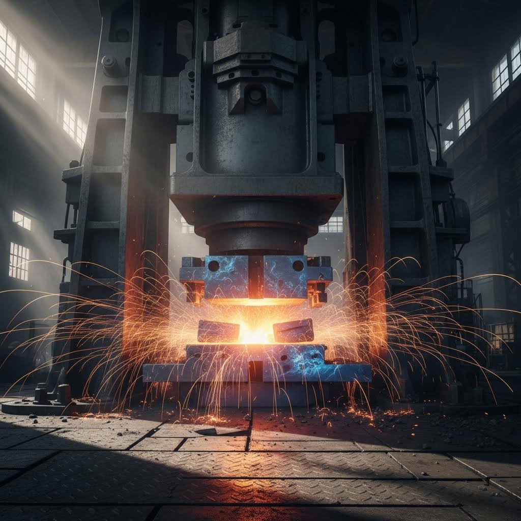
Някога ли сте се чудили как равен лист стомана се превръща в идеално оформена врата на автомобил или в прецизно електронно корпус? Отговорът се крие в процеса на метално пресоване — производствена технология, която оформя нашия модерен свят по начини, за които повечето хора изобщо не мислят.
Металното пресоване, известно също като метално штамповане, е студеноформиращ производствен процес, при който се използват специализирани матрици и високоналягащи преси, за да се превръща равен листов метал в точни тримерни форми чрез постоянно пластично деформиране — без отстраняване на материал.
Така какво представлява металното штамповане на практика? Представете си го като контролирана деформация. За разлика от машинните процеси, при които се отстранява материал чрез рязане, штамповането на метал напълно променя неговата форма. Плоска заготовка влиза в пресата, прилага се огромна сила и излиза готов компонент — всичко това за секунди.
Разбирането на смисъла на штамповането изисква да се направи разлика между него и по-широките категории формообразуване. Макар терминът „формообразуване“ да обхваща всеки процес, при който се оформя метал (включително горещи процеси като ковачество), металното штамповане специфично се отнася до операции по студено формообразуване, извършвани при или близо до стайна температура. Тази разлика е важна, защото студената обработка произвежда детайли с превъзходно повърхностно качество, по-строги допуски и подобрени механични свойства благодарение на упрочняване чрез пластична деформация.
Принципът на студеното формообразуване зад металното штамповане
Какво прави хладното формоване толкова ефективно? Когато приложите сила върху листов метал над неговата граница на текучест, но под неговата пределна здравина, се случва нещо забележително — материала се деформира пластично. Това означава, че промяната във формата става постоянна след отпускане на наложеното налягане.
Физичните принципи зад това включват три взаимодействащи елемента:
- Разпределение на силата: Налягането трябва да се прилага равномерно, за да се предотвратят локални повреди или неравномерна деформация
- Движение на материала: Металът се премества и преподрежда по време на пресоването, като в някои области възниква компресия, докато в други се развива опън
- Геометрия на матрицата: Формата на инструментите точно контролира къде и как се деформира материала
Хладното обработване предлага значителни предимства пред методите за горещо формоване. Според производствени изследвания от IIT Guwahati , детайлите, получени чрез хладно формоване, постигат по-тесни допуски, по-добро качество на повърхността и по-висока здравина благодарение на упрочняване чрез пластична деформация. Освен това елиминирането на необходимостта от загряване значително намалява енергийните разходи.
Как налягането преобразува плоски заготовки в сложни форми
Когато задавате въпроса „какво е штампован метал?“, всъщност питате за трансформация чрез контролирано налягане. Ето какво действително се случва по време на процесите на штамповане на метал:
Парчета равен листов метал — обикновено наричани заготовки — се поставят между секциите на матрицата. Пресата след това прилага сила и материала се деформира, за да съответства на контурите на кухината на матрицата. Това штамповане означава, че метала изпитва напрежения, превишаващи предела му на текучест, което води до пластична деформация и постоянното му преформиране.
Прелестта на штампования метал се крие в повторяемостта. Веднъж правилно настроена, операцията по штамповане може да произвежда хиляди — дори милиони — идентични компоненти. Всяка циклична операция осигурява една и съща прецизна геометрия, което прави този процес идеален за производството в големи серии в автомобилната, авиационно-космическата, електронната и потребителската индустрия.
Какво отличава успешните операции по штамповане от неуспешните? Това се свежда до разбирането на начина, по който се взаимодействат поведението на материала, конструкцията на инструментите и параметрите на процеса. Когато тези елементи са правилно съгласувани, плоският полуфабрикат се превръща в сложна, прецизно изработена детайл за един-единствен бърз ход.
Пълен работен процес от суров материал до готово изделие
Вече сте видели какво постига штамповането на метали — но как всъщност се осъществява тази „магия“? Разбирането на целия работен процес превръща абстрактните понятия в практически приложими знания. Нека преминем стъпка по стъпка през всеки етап — от момента, в който суровият материал пристига, до готовото изделие, което е подготвено за монтаж.
От сурова рула до готово изделие
Представете си голяма рула листов метал, тежаща хиляди фунта. Как тя се превръща в пресни компоненти измервано в хилядни части от инча? Отговорът включва внимателно координирана последователност, която машините за штамповане изпълняват с изключителна последователност.
- Подготовка и подбор на материала: Процесът започва дълго преди метала да докосне штамповъчна преса. Инженерите избират листове или ролки от метал въз основа на техните механични свойства — якост, пластичност, корозионна устойчивост — и икономически фактори. Според National Material Company избраният материал трябва да е съвместим както с процеса на штамповане, така и с функционалността на готовата детайл.
- Обработка и подаване на ролки: Суровите ролки се подлагат на подготовка, включваща рязане, продължително разрязване (слитинг) и изравняване, за да се постигнат необходимите размери и равност. След това автоматизирана система за подаване напредва подготвената лента през штамповъчната машина с точна позиция на метала — често с точност до няколко хилядни от инча.
- Монтаж и подравняване на матрицата: Преди началото на производството техниците монтират комплекта матрици и калибрират пресата. Този критичен етап гарантира правилно течение на материала, достатъчен зазор за металния лист и подходяща подкрепа по време на целия цикъл на штамповане.
- Операцията на пресоване: Докато пресата започва действие, матриците се затварят една към друга и подлагат метала на висока сила и налягане. Това деформира материала според контурите на матрицата — извършвайки операции като рязане на заготовки, огъване, чекане или пробиване, последователно или едновременно.
- Изхвърляне и обработка на детайлите: След всеки ход отстраняващите устройства премахват готовия компонент от носещата лента чисто и без повреди. Отпадъчният материал — както носещата лента, така и избутаният метал — се изхвърля и често се транспортира чрез подземни конвейерни ленти към контейнерите за отпадъци.
- Вторични операции и довършителна обработка: След-штемпеловъчните процеси могат да включват отстраняване на заострени ръбове (дебъринг), почистване, повърхностна обработка и нанасяне на покритие. Тези стъпки подобряват външния вид, издръжливостта и функционалността на штемпелованите детайли.
- Контрол на качеството: През целия производствен процес операторите прилагат реалновременен мониторинг и инспекции, за да се провери дали детайлите отговарят на зададените допуски и стандарти за качество.
Ключовата роля на подравняването и настройката на матриците
Защо подравняването заслужава специално внимание? Защото дори незначителното му нарушаване води до сериозни проблеми. Когато лентовият материал се придвижва през последователни штемпеловъчни операции, той трябва да бъде подравнен с точност от няколко хилядни от инча на всяка станция.
Ето как се постига прецизното подравняване: куршумовидни или конични „пилоти“ влизат в предварително пробитите отвори в лентата, за да осигурят точно позициониране. Това компенсира ограниченията на механизма за подаване, който сам по себе си не може да осигури необходимата точност само чрез дължината на подаването. Според Техническата документация на Уикипедия , тази система „пилот–отвор“ е задължителна, тъй като механизмите за подаване обикновено нямат точността, необходима за многостанционни последователни операции.
Прогресивните щампови матрици и щамповите системи представляват върха на ефективността при непрекъснатото производство. Подаващата система премества лента от метал през всички станции на прогресивна матрица, като всяка станция извършва специфични операции, докато се получи готовата детайл. При всеки ход на пресата се произвежда завършена компонента — скоростта на производство може да надвишава 800 части в минута за определени приложения.
Щамповите машини, конфигурирани за прогресивни операции, изискват специализирани компоненти, които работят в синхрон:
- Подаващи системи (пневматични или механични), които осигуряват прецизно напредване на лентата
- Форми с множество станции за рязане, огъване и формоване
- Изваждачи които чисто отделят готовите компоненти
- Сензори и смазочни системи които следят и оптимизират цикъла на щамповане и пресоване
Системният подход, описан тук — от избора на материала до окончателната инспекция — превръща суровите метални листове в точно оформени компоненти, които обслужват разнообразни индустрии. Но какви конкретно штамповъчни техники правят възможни тези преобразувания? В следващия раздел са представени девет основни метода и случаите, в които всеки от тях трябва да се прилага.
Девет основни метода за штамповка и кога да използвате всеки от тях
Сега, когато сте запознати с целия работен процес, остава един ключов въпрос: кой штамповъчен процес всъщност трябва да използвате? Отговорът зависи от геометрията на детайлите, обема на производството и изискванията към качеството. Нека разгледаме всяка техника, за да можете да вземете обосновани решения за вашите конкретни приложения.
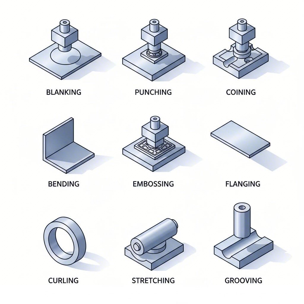
Процесът на метално пресоване включва девет основни техники за обработка на листов метал — всяка от тях е оптимизирана за постигане на различни резултати. Разбирането на това кога да се приложи всеки метод прави разликата между успешни производствени проекти и скъпи грешки.
Изрязване и пробиване за създаване на първоначалната форма
Тези два метода са основата на повечето операции по штамповане, но имат противоположни цели. Бъркането им води до отпадъци от материала и неефективност в производството.
Изсичане изрязва плоски форми от листов метал, като избутаната част става крайният ви продукт. Мислете за това като за производство по метода на „формичките за бисквити“ — „бисквитата“ е това, което запазвате, докато останалата част от листа се превръща в отпадък. Според Master Products , този метод е изключително подобен на пробиването, с изключение на това, че ролите на продукта и отпадъка са разменени.
Кога трябва да изберете штамповане чрез бланкиране? Разгледайте бланкирането, когато имате нужда от:
- Големи обеми идентични плоски компоненти, като например шайби, уплътнения или основни плочи
- Точни външни контури с чисти ръбове
- Първоначални бланки за последващи операции по формоване
Ударяне (също наричано пробиване) създава отвори или изрязани участъци в работната заготовка. При този процес изрязаният материал е боклук, а перфорираната ламарина остава ваш продукт. Тази технология за штамповане се отличава с висока точност при изработването на отвори за крепежни елементи, вентилация или сглобяване.
Отличен пример за штамповане чрез пробиване е производството на електрически корпуси, където за вентилационните шаблони са необходими десетки точно позиционирани отвори. Штамповането на контур (бланкиране) и пробиването често се използват заедно — първо се оформя общата форма, след което в последващи операции се пробиват необходимите отвори.
Точни техники, включително монетна обработка и релефно оформяне
Нуждаете ли се от сложни повърхностни детайли или изключително тесни допуски? Монетовидното штамповане и релефното оформяне осигуряват резултати, които други методи за штамповане просто не могат да постигнат.
Монетарен прилага огромно налягане, за да штампова едновременно и двете страни на работната заготовка, като създава изпъкнали или вдлъбнати елементи с изключителна точност. Както обяснява HLC Metal Parts, този процес създава сложни модели и текстури върху метални повърхности —точно както се произвеждат монетите. Изработката на стомана и други метали чрез тиснене (коининг) води до детайли с допуски, измервани в хилядни от инча.
Изберете коининг, когато приложението ви изисква:
- Паметни предмети, бижута или маркирана фурнитура с лога
- Прецизни тиснати части, изискващи изключителна равност
- Повърхностни елементи, които трябва да издържат износване, без да се деградират
Релief тисне само едната страна на заготовката, създавайки изпъкнали или вдлъбнати модели, докато обратната страна показва огледно изображение. Тази техника подобрява декоративността и добавя визуален интерес към панели, табелки и потребителски продукти.
Изкривяване използва гънкач за преса, за да приложи екстремна сила и деформира метала под определени ъгли, за да се получат V-образни или U-образни компоненти. Този процес на тиснене е основен за производството на корпуси, обвивки, скоби и рамки. Когато имате нужда от ъглови елементи, а не от сложни криви, гъненето осигурява последователни резултати при високи скорости на производство.
Фланширане извива ръбовете около пробитите отвори под ъгъл 90 градуса, създавайки гладки ръбове вместо остри ръбове. Според производствените справочни материали фланцуването подобрява структурната якост, като едновременно повишава безопасността и външния вид. Фланцовани ръбове се срещат при резервоари, тръби, каросерийни панели на автомобили и всякакви приложения, изискващи усилени отвори.
Остъкляване формира изпъкналости или разширени области по металните повърхности чрез изтегляне на материала извън неговите първоначални размери. Тази техника се използва за производството на сложни автомобилни компоненти, като вратични панели и покривни секции, където са от съществено значение гладките и плавни контури.
Завиване завива металните ръбове, за да се образуват цилиндрични форми или гладки, закръглени профили. Този процес се използва за производството на тръби, валове и шарнири, като едновременно елиминира опасните остри ръбове на потребителските продукти.
Нарязване на пазове изрязва канали в повърхностите на листовия метал, създавайки пътища за електропроводка, отводняване или механични връзки. Компонентите, които изискват прецизни жлебове за позициониране или сглобяване, разчитат на тази специализирана техника.
| Име на процеса | Основно приложение | Типични индустрии | Диапазон на дебелина на материала |
|---|---|---|---|
| Изсичане | Изрязване на плоски форми от листов материал | Автомобилна промишленост, електроника, битова техника | 0,5 мм - 6 мм |
| Ударяне | Създаване на отвори и изрязвания | Отопление, вентилация и климатизация (HVAC), електротехника, строителство | 0,3 мм – 12 мм |
| Монетарен | Високоточни повърхностни детайли | Бижута, валута, прециозни компоненти | 0,2 мм – 3 мм |
| Изкривяване | Ъглова деформация за рамки/конзоли | Мебели, автомобилна промишленост, аерокосмическа промишленост | 0,5 мм - 10 мм |
| Фланширане | Формиране и усилване на ръбове | Автомобилна промишленост, резервоари, тръби | 0,8 мм – 6 мм |
| Остъкляване | Повърхностно разширение за сложни контури | Автомобилни табла, аерокосмическа промишленост | 0,6 мм – 4 мм |
| Релief | Изпъкнали декоративни орнаменти | Битова техника и стоки, табелки, занаятчийски изделия | 0,3 мм – 2 мм |
| Завиване | Свити ръбове и цилиндрични форми | Шарнири, тръби, компоненти за безопасност | 0,4 мм - 3 мм |
| Нарязване на пазове | Създаване на канали за връзки | Електрическа и механична сглобка | 0,5 мм – 4 мм |
Изборът на подходящия процес за штамповане изисква съпоставяне на изискванията към вашата детайлна част с възможностите на съответната технология. Вземете предвид сложността на геометрията, изискванията към допуските, обема на производството и характеристиките на материала. Често производителите комбинират няколко технологии в прогресивни штамповъчни операции — отрязване на първоначалната форма, пробиване на монтажни отвори, огъване на фланци и тиснене на идентификационни маркировки — всичко това в една непрекъсната последователност.
С девет основни технологии на разположение може би се чудите кое оборудване осигурява тези възможности най-ефективно. В следващия раздел се разглеждат типовете преси — механични, хидравлични и сервопреси — които ще ви помогнат да подберете машината, най-подходяща за вашите конкретни производствени изисквания.
Избор между механични, хидравлични и серво преси
Овладели сте деветте техники за клеймване — но ето реалността: дори най-добрата техника не дава резултат без подходящия прес за клеймване на метали. Изборът на вашия прес за клеймване на метали не е просто търговско решение; той директно влияе върху качеството на детайлите, скоростта на производството и вашата печалба. Нека разгледаме трите основни типа преси, за да можете да подберете оборудването според конкретните си производствени нужди.
Механични преси за производство с висока скорост
Нуждаете ли се от максимална скорост за производство в големи обеми? Традиционните механични преси за клеймване продължават да бъдат работните коне на отрасъла — и това е напълно оправдано. Според Техническото сравнение на Stamtec механичните преси постигат най-високите скорости на производство, особено при обработка на относително плоски детайли с по-прости и по-плитки изисквания към формообразуването.
Какво прави стоманения прес с механичен привод толкова ефективен? Отговорът се крие във физиката на маховика. Тежък маховик натрупва ротационна енергия и след това я освобождава чрез съединително-спирачен механизъм при всеки ход. Тази конструкция осигурява:
- Най-високи скорости на ходове сред всички типове преси — идеални за операции с прогресивни матрици
- Висока точност и повтаряемост за последователно качество на детайлите
- Простота при настройка и експлоатация с проверена и надеждна технология
- Относително ниска първоначална цена в сравнение с сервоприводните алтернативи
Обаче механичните системи имат ограничения. Дължината на хода обикновено е фиксирана, профилите на скоростта на плунжера не могат да се променят в рамките на един цикъл, а пълната номинална мощност се постига само близо до долна мъртва точка. За автомобилни, домакински и технически части, които се обработват от руло чрез прогресивни или трансферни матрици, тези ограничения рядко имат значение — но дълбоко изтеглени или сложни формовани части може да изискват други решения.
Хидравлични и серво системи за прецизно управление
Какво става, ако вашите детайли изискват дълбоко изтегляне, сложни форми или задържане в долна мъртва точка? Хидравличните преси се отличават в тези случаи — макар и да жертват скорост в полза на универсалност.
Станция за стоманени штамповки с хидравличен привод предлага променлива дължина на хода, контрол на движението на плъзгача в целия диапазон и пълна работна енергия при всяка скорост. Представете си формирането на резервоари, цилиндри или компоненти с формата на чинии — тези части изискват значително течение на материала по време на процеса на пресоване. Хидравличните системи осигуряват пълна пресова мощност във всяка точка от хода, което ги прави идеални за такива изискващи приложения.
Компромисът? Хидравличните преси обикновено работят по-бавно от механичните им алтернативи и осигуряват по-ниска точност и повтаряемост. Но когато производствената скорост отстъпва място на възможностите за формиране, хидравличната технология остава предпочитаният избор за сложни геометрии.
Сега разгледайте сервопресата — машина за штамповане на листови метали, която комбинира механична ефективност с хидравлична гъвкавост. Сервотехнологията заменя традиционните маховик, съединител и спирачка с високомощни двигатели, които осигуряват програмируеми профили на хода, прецизно управление на движението на плунжера и променлива скорост дори в рамките на един цикъл.
Според индустриални данни механичните сервопреси предлагат:
- Променливи профили на хода които могат да се персонализират за всяка отделна задача
- Пълна работна енергия при всяка скорост — дори по време на бавни формовъчни операции
- Честота на цикли, приближаваща тази на традиционните механични преси в много приложения
- Висока точност и повтаряемост с програмируема прецизност
Но има и уловка: сервосистемите имат значително по-високи първоначални разходи. Съществуват два типа задвижващи технологии: системи с помощна кинематична връзка, използващи стандартни AC серводвигатели (по-икономични), и директни задвижващи системи, използващи собствени високомоментни двигатели (максимална производителност).
За операции с преси за трансферно штамповане, които обработват сложни многопозиционни работни процеси, сервотехнологията все повече доминира. Възможността за програмиране на уникални профили – включително дълбоко изтегляне, топло формоване, комбинирано пресоване и симулация на движението на лостови механизми – отваря производствени възможности, които традиционните системи просто не могат да осигурят.
| Параметри | Механична преса | Hidравлическа преса | Серво прес |
|---|---|---|---|
| Диапазон на скоростта | Най-висока (най-добра за прогресивни матрици) | Най-бавна (ограничена по скорост) | Висока (приближава механичната) |
| Капацитет по тонаж | Пълна близо до долна мъртва точка | Пълна през целия ход | Пълна близо до долна мъртва точка |
| Прецизен нивелир | Висока точност и повтаряемост | По-ниска точност | Най-висока програмируема прецизност |
| Консумация на енергия | Умерена (зависи от маховика) | Непрекъсната работа на помпата | Енергийно ефективна (по заявка) |
| Най-добри приложения | Високоскоростни плоски части, прогресивни матрици | Дълбоки изтегляния, сложни форми, операции с пауза | Многофункционална — изтегляне, формоване, пробиване |
| Начална цена | Относително ниска | Относително ниска | Относително висока |
| Гъвкавост на хода | Фиксирана (ограничена регулировка) | Пълно променлива | Пълно програмируем |
И така, коя машина за метално штамповане отговаря на нуждите на вашата производствена линия? Рамката за вземане на решение е проста: механичните преси осигуряват непревзойдена скорост, но липсва им гъвкавост; хидравличните преси предлагат универсалност за сложни детайли, но жертват производителността; серво-пресите предлага най-доброто от двете страни при по-висока цена.
Внимателно преценете своя производствен асортимент. Ако произвеждате високи обеми сравнително прости детайли, механичните преси максимизират ефективността. За малки обеми сложни компоненти, изискващи значително деформиране на материала, икономически оправдани са хидравличните системи. А когато имате нужда от гъвкавост при работа с разнообразни семейства детайли и високи изисквания към качеството, серво-технологията оправдава по-високите инвестиции.
След като сте избрали пресата, предстои още едно важно решение: кои материали показват най-добра производителност при избраната ви процесна технология за штамповане? Следващият раздел ви води през подбора на материали — съгласуване на металните свойства с изискванията на процеса за постигане на оптимални резултати.
Ръководство за избор на материали за оптимални резултати при штамповане
Вие сте избрали типа преса и сте определили подходящите техники за штамповане — но тук много проекти се провалят: изборът на неподходящ метал за штамповане. Подборът на материал не се свежда до избиране на най-скъпата възможност; той се състои в намирането на идеалния баланс между формоустойчивост, експлоатационни характеристики и разходи. Ако вземете погрешно решение, ще се сблъскате с пукнатини, прекомерен еластичен възврат (springback) или детайли, които се повреждат по време на експлоатация.
Какво прави един метал по-подходящ за штамповане от друг? Четири ключови свойства определят штампуемостта:
- Пластичност: Доколко металът може да се удължи, преди да се наруши цялостта му — критично за дълбоко штамповане и сложни форми
- Пределна твърдост: Нивото на напрежение, при което започва постоянната деформация — влияе върху необходимата тонажна мощност и еластичния възврат (springback)
- Увличане чрез деформация: Наскоро материалът укрепва по време на деформация — влияе върху многоетапните операции
- Поведение при еластично възстановяване: Еластичното възстановяване след формоването — определя постижимите допуски и необходимостта от компенсация на матрицата
Според CEP Technologies изборът на подходящи материали за метално штамповане изисква балансиране на крайната употреба на детайла, формоваемостта, корозионната устойчивост и разходите. Нека разгледаме как се проявява всяка основна категория материали.
Класове стомана и техните характеристики при штамповка
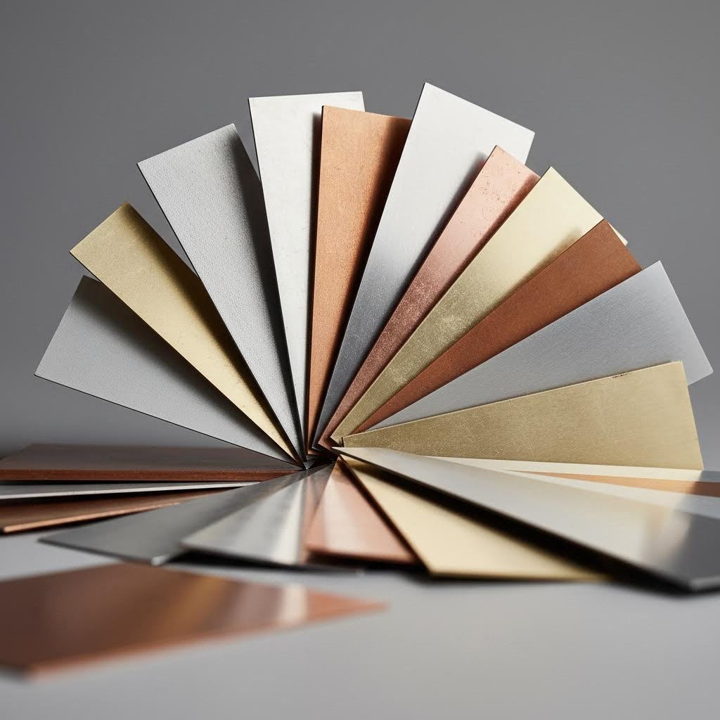
Стоманата доминира в приложенията за метално пресоване поради добре обосновани причини — тя предлага изключителна якост, проверена формоваемост и икономичност в широк спектър от приложения. Обаче терминът „стомана“ обхваща десетки марки със значително различни характеристики при штамповане.
Въглеродна стомана остава основният материал за производство в големи обеми. Тези стомани са налични в ниско-, средно- и високовъглеродни варианти и предлагат отлична формоваемост при конкурентни цени. Нисковъглеродните марки (със съдържание на въглерод под 0,30 %) се штампват лесно и са подходящи за автомобилни скоби, корпуси на битови уреди и общи конструктивни компоненти. По-високото съдържание на въглерод увеличава твърдостта, но намалява пластичността — важни аспекти при избора на материали за штамповка на метали за вашата конкретна употреба.
Стерилизация на стомана се използва за приложения, изискващи корозионна устойчивост и висока якост. Неръждаемата стомана от клас 304 осигурява пределна якост при опън над 515 MPa и устойчивост към солен разпръскван според материала на Tenral, превишаваща 48 часа. Това я прави идеална за корпуси на медицинско оборудване, компоненти за хранителнопреработвателната промишленост и външни приложения. Клас 430 предлага по-ниска цена за конструктивни части, при които не се изисква строга защита срещу ръжда.
Обаче неръждаемата стомана създава предизвикателства при штамповката. По-високата граница на текучест изисква по-голяма пресова сила, докато по-високите темпове на упрочняване при деформация изискват внимателно планиране на процеса за многостепенни операции. Явлението „отскок“ е по-изразено в сравнение с меката стомана — очаквайте по-тесни допуски за матриците и вероятно няколко итерации на формоването.
Високоякостни нисколегирани (HSLA) стомани предоставят подобрени механични свойства за автомобилни и аерокосмически приложения. Тези материали позволяват намаляване на теглото чрез по-тънки листове, като запазват структурната цялост. Какъв е компромисът? Намалената пластичност и увеличеният отскок изискват по-съвършена конструкция на матриците и по-строг контрол на процеса.
Предварително оцинкованите стомани опростяват производството, като елиминират финишните операции след штамповката:
- Галванзирана стомана: Дебелина на цинковото покритие от 8 μm или повече осигурява основна защита срещу ръжда при ниска цена — идеално за крепежни скоби на шасита и панели за битова техника
- Оникелирена стомана: По-висока корозионна устойчивост в сравнение с цинка намалява изискванията към финишната обработка за изискващи приложения
Съображения относно алуминиеви и медни сплави
Когато намаляването на теглото определя изискванията към вашето проектиране, процесът на штамповане на алуминий става задължителен. При плътност само 2,7 g/cm³ — приблизително една трета от тази на стоманата — штампованият алуминий осигурява значително намаляване на теглото, без да се жертва функционалността.
Штамповани алуминиеви части се отличават в приложения, изискващи:
- Леки компоненти за топлоотводи на базови станции за 5G и електронни корпуси
- Отлична термична и електрична проводимост
- Добра корозионна устойчивост без допълнителни покрития
- Висока рециклируемост за производство, насочено към защита на околната среда
Сплавта 6061-T6 е популярна избор за прецизно штамповане на алуминий, като предлага здравина при опън между 110–500 MPa и превъзходна формоваемост. Един практически пример: компания в областта на комуникациите постигна подобряване на ефективността на топлоотвеждането с 25 % и намаляване на теглото под 100 g чрез замяна на медните топлоотводи с прецизно штампвани топлоотводи от алуминиева сплав 6061-T6.
Мекотата на алуминия прави формоването му по-леко, но създава предизвикателства при контрола на еластичното връщане и защитата на повърхностния финиш. Изборът на смазка става критичен — неподходящата смазка води до задиране и повърхностни дефекти, които компрометират както външния вид, така и работата.
Медно штамповане се прилага там, където е от първостепенно значение електрическата проводимост. При проводимост до 98 % медта се използва за микроконтакти, пружини за SIM карти и клеми за електрически проводници в електрониката и телекомуникациите. Материалът се пробива чисто в сложни форми, макар относителната му мекота да изисква внимателно обращение, за да се предотвратят повърхностни повреди.
Латун (сплав от мед и цинк) предлага привлекателен компромис. Месинг H62 постига твърдост HB≥80 и превъзходна обработваемост, като не изисква вторична обработка след штампането. Тази сплав се използва в механизми за умни врати, съединения за климатични системи в автомобили и приложения, изискващи както електрическа проводимост, така и устойчивост на износване.
Фосфорен бронз съчетава мед, калай и фосфор за изключителна еластичност, корозионна устойчивост и износостойкост. Бериловата мед осигурява още по-висока якост за изискващи приложения и може да се термообработва за допълнителна твърдост — макар цената на материала да е значително по-висока.
Дебелината на материала пряко влияе както върху избора на технологичния процес, така и върху изискваните натоварвания. CEP Technologies декларира възможности за штамповка на лентови материали с дебелина между 0,002 инча и 0,080 инча, като капацитетът на пресите варира от 15 до 60 тона за малки и средни детайли. По-дебелите материали изискват пропорционално по-големи сили и могат да ограничат постижимите геометрии — особено минималните радиуси на огъване, които обикновено са пропорционални на дебелината на материала.
| Вид материал | Якост на опън (MPa) | Плътност (g/cm3) | Устойчивост към солена плевел | Оптимални приложения |
|---|---|---|---|---|
| Алуминиеви сплавове | 110-500 | 2.7 | 24–48 ч. | Топлоотводи, електронни корпуси, леки конструкции |
| Неръжавеща оц (304) | ≥515 | 7.9 | ≥48 ч. | Медицински устройства, хранително оборудване, външни компоненти |
| Мед | 200-450 | 8.9 | 12-24H | Електрически контакти, клеми, конектори |
| Месинг (H62) | 300-600 | 8.5 | 24–36 ч. | Механизми за заключване, фитинги за климатични системи, декоративни фурнитури |
| Оцinkовано желязо | ≥375 | 7.8 | ≥24 ч. | Шаситни скоби, панели за битова техника, детайли с ограничени разходи |
Връзката между избора на материал и постижимите допуски заслужава внимателно внимание. По-твърдите материали, като неръждаемата стомана, проявяват по-голямо еластично възстановяване (springback), което изисква по-строги допуски за матриците и потенциално няколко операции по формоване, за да се постигнат окончателните размери. По-меките метали, като алуминия, лесно се формоват, но може да се наложи допълнителна подкрепа по време на обработката, за да се запази размерната стабилност. Когато изискванията към допусците са критични, изпитването на материала по време на прототипирането става задължително — теоретичните изчисления имат ограничена приложимост за предвиждане на реалното поведение.
След като изборът на материал е разбран, друг важен фактор изисква внимание: инструментите, които превръщат плоския полуфабрикат в готови компоненти. Следващият раздел разглежда основите на проектирането на матрици — прецизното инженерство, което прави възможно точното и повтаряемо пресоване на метал.
Основи на проектирането на инструменти и матрици
Избрали сте перфектния материал и сте го съчетали с подходящия прес—но ето истината, която разделя успешните операции по штамповане от скъпите провали: вашата инструментална оснастка решава всичко. Дори най-добрите материали и машини произвеждат брак, ако се използват заедно с лошо проектирани или неподдържани матрици. Разбирането на основите на инструменталната оснастка за метално штамповане превръща вас — като купувач на компоненти — в информиран партньор, способен да оценява доставчиците и да предотвратява проблеми с качеството, преди те да възникнат.
Ключови компоненти на штамповата матрица и техните функции
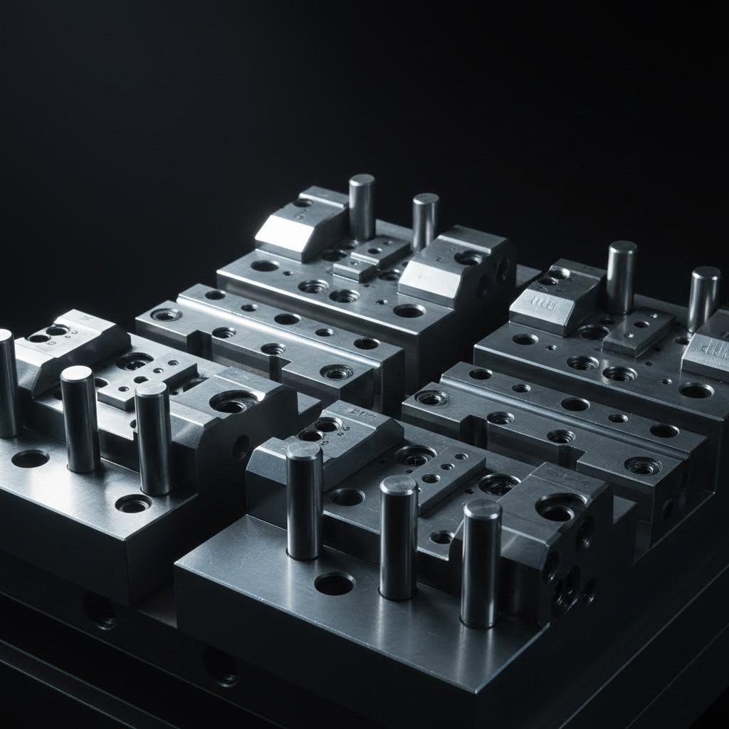
Какво точно се случва вътре в една штампова матрица? Представете си я като прецизна машина в рамките на друга машина — десетки компоненти, които работят в идеална синхронизация, за да превръщат равен метал в сложни форми. Според техническото ръководство на Evans Metal Stamping следните компоненти са задължителни за всяка прогресивна матрица:
- Набор матрици: Основата, която удръжа всички останали компоненти в точна подравненост — обикновено се състои от горна и долна плоча с водачни пинове
- Пробойници: Мъжките инструменти, които проникват в материала или го формират чрез налягане в съответните кухини на матрицата
- Матрични бутони (втулки): Закалени вставки, които приемат пробойниците и определят геометрията на отворите — заменяеми при износване
- Държач на пробойници: Фиксира пробойниците в точни позиции и предава силата от плунжера на пресата
- Избутваща плоча: Отстранява отпадъчния материал от пробойниците след всеки ход и поддържа заготовката равна по време на операциите
- Пилотни пинове: Ръководни елементи с формата на куршум или конус, които навлизат в предварително пробитите отвори, за да осигурят прецизно позициониране на лентата
- Пространство за отпадъчен материал: Проектирани отвори, които позволяват на пробития материал да падне свободно, без да се заклещва
Защо толкова много се набляга на зазора между пробойника и матрицата? Представете си рязане на хартия с тъпи ножици спрямо остри — принципът е приложим и в промишлени мащаби. Правилният зазор (обикновено 5–10 % от дебелината на материала от всяка страна) осигурява чисто срязване без излишни заострени ръбове (зъбчета) или преждевременно износване на инструмента. Ако зазорът е твърде малък, пробойниците се заклещват или се чупят. Ако е твърде голям, получавате неравни ръбове, които изискват вторична операция за заравняване.
Отделителната плоча заслужава специално внимание във всеки проект за штамповане на листов метал. Освен че просто отстранява материала от пробойниците, тя изпълнява и функцията на притискаща плоча, която удръжа заготовката равна по време на формовъчните операции. Отделителните плочи с пружинно задвижване осигуряват контролирано усилие, което предотвратява образуването на гънки, като в същото време позволява правилно течение на материала при дълбоко изтегляне или сложни огъвания.
Пилотните штифтове решават проблем, който механизми за подаване сами по себе си не могат да преодолеят. Когато лентовият материал се придвижва през прогресивни матрици, е необходимо позиционирането да бъде извършено с точност от няколко хилядни от инча — но подаващите устройства обикновено не осигуряват такава прецизност. Пилотите влизат в предварително пробитите отвори, за да издърпат лентата в точно съответствие преди всяка операция. Без тази корекция натрупаните грешки при позиционирането биха направили многопозиционните прогресивни операции невъзможни.
Проектиране на прогресивни матрици за сложни детайли
Когато имате нужда от производство на сложни геометрии в големи количества, штамповането с прогресивни матрици става предпочитаният метод. Но какво отличава отлично проектирането на штамповане от просто задоволителните подходи?
Според обзора на Kenmode за прогресивни матрици, проектирането на матрици за производство на прецизни детайли е един от най-критичните етапи за гарантиране на дългосрочен производствен успех. Прогресивните матрици комбинират множество операции — рязане, пробиване, формоване и огъване — в един-единствен инструмент, който извършва всички стъпки, докато лентовият материал напредва през последователни станции.
Връзката между сложността на матрицата и геометрията на детайла следва ясна закономерност. Прости плоски детайли с отвори изискват само режещи станции. Добавянето на огъвания води до въвеждане на формовъчни станции с прецизни зазори. Сложните триизмерни форми изискват внимателно подредени операции с междинни носители, които запазват цялостта на лентата до финалното отрязване.
Пропускните надрези играят ключова роля при операциите с прогресивни шаблони. Тези стратегически разположени изрязвания в носителните ленти позволяват формираните елементи да минават през последващите станции, без да се сблъскват помежду си. При липса на правилно проектиран пропуск повдигнатите релефни елементи или огънатите фланци ще се сблъскат с компонентите на шаблона — което спира производствения процес и поврежда инструментария.
Тук съвременните технологии трансформират традиционните възможности за проектиране на штамповани изделия. Напредналата CAE-симулация (компютърно подпомогнато инженерство) по време на проектирането на шаблоните предотвратява дефекти и намалява броя на итерациите — като идентифицира потенциални проблеми като намаляване на дебелината на материала, образуване на гънки или еластично връщане още преди да е направена първата стоманена резка. Компании като Shaoyi използват CAE-симулация, подкрепена от сертификат IATF 16949, за постигане на 93 % първоначален процент на одобрение за прецизни штампови шаблони, предлагайки икономически ефективна инструментовка, която отговаря на стандартите на производителите на оригинално оборудване (OEM) — от бързо прототипиране до производство в големи обеми.
Оборудването за метално штамповане, конфигурирано за прогресивни операции, трябва да осигурява място за сложни матрични комплекти, като в същото време поддържа високата прецизност на подравняването, която тези инструменти изискват. Функции като подложки за регулиране осигуряват възможност за настройка, спирачни блокове контролират напредването на лентата, а сензори следят точността на подаването и откриват случаи на неправилно подаване преди да се причини повреда.
Практики за поддръжка на матриците за постигане на постоянство в качеството
Дори най-съвършените стоманени штамповъчни матрици се износват с течение на времето. Режещите ръбове затъпяват, зазорите се увеличават поради износване, а подравняването се променя вследствие многократни удари. Внедряването на правилни протоколи за поддръжка удължава живота на матриците и предотвратява отклонения в качеството, които водят до отхвърляне на детайлите.
- Редовни графици за инспекция: Изследване на режещите ръбове, формиращите повърхности и елементите за подравняване през определени интервали, базирани на броя на ходовете — не само когато възникнат проблеми
- Превантивно заостряне: Прегризайте пробойниците и матриците преди ръбовете да се износят до степен, при която заострените ръбове стават неприемливи — обикновено всеки 20 000–50 000 хода, в зависимост от материала
- Мониторинг на зазорите: Редовно измервайте и документирайте зазорите между пробойницата и матрицата и заменяйте втулките и компонентите, преди износването да надхвърли допустимите граници
- Управление на смазването: Поддържайте подходящи системи за смазване, които намаляват триенето, удължават срока на експлоатация на компонентите и осигуряват равномерно течение на материала
- Проверка на съосността: Редовно проверявайте посадката на водачните пинове и взаимното разположение на водачните отвори — дори незначителна несъосаност се натрупва и води до сериозни проблеми с качеството по време на серийното производство
- Документиране и проследяване: Документирайте всички поддръжки, броя на ходовете и направените корекции, за да се установят базови показатели за предиктивна поддръжка
Според Ръководството на JV Manufacturing , избирането на партньор със здрави процеси за осигуряване на качеството — включително протоколи за инспекция и сертификати като стандарти ISO — гарантира, че всеки инструмент и матрица отговарят на точните допуски и стандарти за производителност. Търсете оператори на машини за метално штамповане, които водят подробни записи за поддръжката и предлагат поддръжка след доставката за производството на прецизни штамповани части.
Инвестицията в правилната поддръжка на матриците дава резултати, които надхвърлят само качеството на частите. Добре поддържаните машини за штамповане имат по-малко непланирани спирания, произвеждат по-постоянен изход и осигуряват по-ниски разходи на част през целия жизнен цикъл на инструментариума. При оценката на потенциални производствени партньори техните практики за поддръжка разкриват толкова много за очакваните резултати по отношение на качеството, колкото и техните списъци с оборудване.
След като основите на изработването на инструменти са разбрани, остава един критичен въпрос: как да идентифицирате и предотвратите дефектите, които компрометират качеството на штамповани части? В следващия раздел са представени често срещаните проблеми при штамповане заедно с тяхната коренна причина — което ви дава знанията, необходими за точно определяне на изискванията за качество и ефективна оценка на възможностите на доставчиците.
Стратегии за контрол на качеството и предотвратяване на дефекти
Вие сте инвестирал в прецизни инструменти и сте избрали подходящите материали — но ето неприятната истина: дефектите все пак възникват. Разликата между световнокласни производствени операции по штамповане и неуспешни производители не е в напълно избягване на проблемите; а в разбирането на причините за възникване на дефектите и тяхното предотвратяване, преди да са компрометирали вашето производство. Нека разшифроваме инженерните принципи зад често срещаните провали при штамповане, за да можете с увереност да формулирате изискванията за качество.
Всеки метален част, изработена чрез штамповане, разказва историята на процеса, който я е създал. Бръчките показват недостатъчна държаща сила. Пукнатините разкриват прекомерно разтягане на материала. Зазъбванията сочат износени инструменти, които трябваше да бъдат заострени хиляди ходове по-рано. Когато разбирате тези причинно-следствени връзки, вие се превръщате от човек, който отхвърля дефектни части, в човек, който предотвратява тяхното производство още от самото начало.
Идентифициране и предотвратяване на често срещани дефекти при штамповане
Защо штампованите метални части не издържат проверката? Според техническата документация на Neway Precision, често срещаните дефекти включват зазъбвания, бръчки, пукнатини, еластично връщане (springback), повърхностни абразии и отклонения в размерите — всеки от тях компрометира функционалността и съответствието, особено в приложения с критична безопасност в автомобилната, енергийната и електронната индустрия.
Бръчки се проявяват като локални вълнообразни дефекти, обикновено по ръбовете на фланците или в дълбоко изтеглените области. Каква е причината за тях? Небалансирана сила на държача на заготовката или прекомерен материален поток по време на формовъчните операции. Когато материала не е правилно ограничаван, той се огъва вместо да се разтяга равномерно. Решението включва коригиране на налягането на държача на заготовката, оптимизиране на конфигурацията на изтеглящите гребени или преразработване на пътя на материалния поток през матрицата.
Пукнатини и скъсвания представляват противоположния проблем — материал, който е разтеглен над своите граници. Тези дефекти често се появяват при високоякостни стомани като DP780 или TRIP980 с ограничена удължимост, особено при остри радиуси или в зони, изпитващи нееднородна деформация. Мерките за предотвратяване включват избор на материали с достатъчна пластичност, увеличаване на радиусите на матрицата (R ≥ 4t, където t е дебелината на материала) и евентуално прилагане на горещо формоване за трудни приложения.
Връщане след извиване разочарова инженерите, защото детайлът изглежда правилен в матрицата, а след това променя формата си след изваждането. Това еластично възстановяване се дължи на това, че не цялото деформиране по време на формоването е пластично; част от него остава еластично и се възстановява, когато силата бъде премахната. При детайли от напреднали стомани с висока якост ъглите на еластичното възстановяване могат да достигнат 6–10°, което значително влияе върху окончателната геометрия. Компенсацията изисква използване на CAE-симулации по време на проектирането на матрицата, стратегии за надвиване (overbending) и понякога допълнителни операции по клеймене (coining), за да се закрепят окончателните размери.
Заешки опашки —острите остатъчни ръбове, получени при пробиване или изрязване, — обикновено указват на износени матрици или неправилно разстояние между пуансона и матрицата. Промишлените стандарти често отхвърлят височина на заострени ръбове (бур) над 0,1 мм върху повърхности, от значение за безопасността и уплътняването. Предотвратяването изисква поддържане на правилно разстояние (обикновено 10–15 % от дебелината на материала) и внедряване на цикли за инспекция на инструментите всеки 10 000–50 000 удара, в зависимост от твърдостта на материала.
Размерни отклонения възникват, когато несъосаността на инструмента или отклонението на пресата водят до това изработените метални компоненти да надвишат допустимите отклонения. Допуските за части, които надхвърлят ±0,2 мм, често излизат извън спецификациите за геометрични размери и допуски (GD&T), което прави компонентите непригодни за прецизни сглобки.
| Вид на дефекта | Основна причина | Метод за предотвратяване | Метод за откриване |
|---|---|---|---|
| Бръчки | Недостатъчно усилие на държача на заготовката; прекомерно течение на материала | Увеличаване на налягането на държача; оптимизиране на изтеглящите гребени; преосмисляне на течението на материала | Визуална инспекция; профилометрия на повърхността |
| Пукнатини/фрактури | Прекомерно удължаване; остри радиуси; недостатъчна пластичност на материала | Избор на материали с по-висока пластичност; увеличаване на радиусите на матрицата; разглеждане на горещо формоване | Визуална инспекция; изпитване с проникващо вещество |
| Връщане след извиване | Еластично възстановяване при сплави с висока здравина на опън | CAE симулация; компенсация на прекомерно огъване; операции по клеймене | Измерване с координатно-измервателна машина (CMM); оптичен компаратор |
| Заешки опашки | Износени инструменти; неправилно разстояние между пуансона и матрицата | Поддържайте зазор от 10–15 %; прилагайте проверки на всеки 10 000–50 000 хода | Визуална инспекция; измерване на височината на заострените ръбове (бурите) |
| Повърхностни драскотини | Недостатъчно смазване; замърсяване с частици; грапави повърхности на матриците | Прилагайте микросмазване; предварително почиствайте материала; полирайте матриците до Ra 0,2 μm | Визуална инспекция при контролирано осветление |
| Размерни неточности | Неправилно подравняване на инструмента; отклонение на плунжера на пресата; вариация в дебелината на материала | Добавете водачи; проверете успоредността на пресата; сертифицирайте входящия материал | Инспекция с КММ; калибри за „да“/„не“ |
Мерки за контрол на качеството за осигуряване на последователен резултат
Идентифицирането на дефекти след тяхното възникване е реактивно — и скъпо. Съвременните операции по штамповане наблягат на мониторинг по време на процеса и статистически контрол на процеса (SPC), за да се засичат отклоненията, преди те да доведат до брак.
Как изглежда ефективният контрол на качеството за компонентите, получени чрез штамповане? Според Стандартите за акредитация на NIMS , квалифицираните техници трябва да демонстрират експертни познания по методите за записване при SPC, стандарти за съответствие на материала и способността да различават статуса „да“/„не“ както за атрибутивни, така и за променливи допуски.
Ефективните системи за контрол на качеството на штамповани части включват няколко нива:
- Инспекция на първия детайл: Пълна размерна верификация преди започване на серийното производство — чрез използване на 3D скенери за сравнение на физическите части с цифровите модели
- Сензори в матрицата: Реалновременен мониторинг на натоварването на пресата, подаването на материала и формиращите сили, за да се засичат аномалии, преди да се натрупат дефектни части
- Статистическо пробоподготовка: Периодично измерване на критичните размери с резултатите, нанесени на контролни диаграми, за идентифициране на отклонения в процеса
- Проследимост на материала: Сертифициране на партиди, гарантиращо последователни механични свойства, особено важно за стоманени марки с висока якост и ниско съдържание на легиращи елементи (HSLA) и напреднали високоякостни стомани
От гледна точка на процесното инженерство се подчертава разбирането на причината „защо“ възникват дефектите, а не само тяхното идентифициране. Когато се появи пукнатина в шампираните стоманени детайли, въпросът не е само „какво се повреди?“, а „кой параметър на процеса се промени, за да предизвика тази повреда?“. Това мислене, насочено към установяване на коренната причина, трансформира контрола на качеството от инспекция в превенция.
Правилното проектиране и поддържане на шаблоните остават основата за предотвратяване на дефекти. Както беше обсъдено в предишния раздел, редовните инспекционни цикли, профилактичното заостряне и контролът на зазорите решават проблемите в самия им източник. Изчерпателно отраслово ръководство препоръчва използването на софтуер за компютърно-помощно инженерство (CAE), като AutoForm, за симулиране на движението на материала, еластичното връщане и разпределението на напреженията по време на фазата на проектиране — това позволява да се засекат потенциални дефекти още преди производството на инструментите.
Преходът към интелигентно производство ускорява тези възможности. Според отраслови проучвания 74 % от доставчиците на първо ниво за автомобилната промишленост вече използват аналитика на данни в реално време, за да минимизират нивото на дефекти и да намалят времето за смяна на инструментите с 20–30 %. Технологиите за цифрови двойници осигуряват непрекъснато сравняване между действителните производствени данни и симулираната производствена производителност — това позволява да се идентифицират отклонения, които предсказват проблеми с качеството още преди те да се проявят в готовите детайли.
След като стратегиите за предотвратяване на дефекти са разбрани, остава практически въпрос: къде всъщност отиват тези прецизно штамповани метални части? В следващия раздел се разглеждат приложенията им в различни отрасли — от каросерийни панели за автомобили до корпуси за медицински устройства — и се показва как штамповането на метали осигурява стойност в разнообразни сектори.
Приложения в индустрията – от автомобилна до медицинска техника
Сега, когато знаете как да предотвратявате дефекти и да поддържате качеството, ето и вълнуващата част: къде всъщност завършват всички тези прецизно штамповани компоненти? Процесът на штамповане на метали засяга почти всеки отрасъл, който можете да си представите — от автомобила във вашия гараж до смартфона в джоба ви. Нека разгледаме конкретни приложения на штамповането в основните отрасли и да разберем защо производителите последователно избират штамповането на метали пред други методи за изработка.
Автомобилни и аерокосмически прецизни компоненти
Когато погледнете съвременен автомобил, вие виждате в действие процеса на метално штамповане за автомобилна индустрия — навсякъде. Според обобщената информация за производството на Alsette, штамповането произвежда огромен спектър от автомобилни компоненти — от лесно забележимите външни панели до скритите структурни усилващи елементи, които осигуряват безопасността на пътниците при сблъсквания.
Защо автомобилното штамповане доминира в производството на превозни средства? Три фактора правят този процес незаменим:
- Бързина и ефективност: Съвременните преси произвеждат стотици или хиляди части на час — нещо съществено за поддържане на темпа на изискванията на монтажната линия
- Изгодност при мащабно производство: След като матриците бъдат изработени, разходите по част намаляват значително при серийно производство с висок обем
- Оптимизация на отношението якост/тегло: Сложни штамповани геометрии максимизират якостта, докато използват сравнително тънки листови метали, което подобрява икономичността на горивото и далечината на електромобили (EV)
Автомобилното метално штамповане произвежда компоненти от три основни категории:
Каросерийни панели (затварящи елементи и обвивка):
- Врати (външни и вътрешни панели)
- Капаци на двигателя и багажника
- Крила и странични панели (четвърт панели)
- 天井 панели
Тези части изискват повърхностна обработка от „клас А“ — напълно гладка и без дефекти, тъй като са много видими за клиентите.
Структурни компоненти (каросерия в бяло):
- Колони тип А, В и С, поддържащи покрива
- Секции на пода и рамкови релси
- Напречни греди и сглобени преградни стени
- Вътрешни арки на колелата
Тези штампувани части имат приоритет върху краш-перформанса и често използват стомани с висока якост за защита на пътниците.
Функционални компоненти:
- Монтажни скоби за двигатели, окачване и радиатори
- Топлоизолационни екрани и усилващи плочи
- Седалки и механизми за регулиране
- Резервоари за гориво
Аерокосмическите приложения изискват още по-висока прецизност — а штамповането я осигурява. Според документацията на Manor Tool за аерокосмическата индустрия точността, фината детайлизация и издръжливостта на металните штампувани части ги правят идеални за тази област, където оборудването трябва да отговаря на строги стандарти за качество в рамките на изключително тесни допуски.
Штамповането от неръждаема стомана произвежда критични аерокосмически компоненти, включително:
- Системи за поддържане на налягане: Компресори и клапани, съставени от штампувани компоненти, осигуряват безопасно поддържане на налягането в кабините на самолетите на височина
- Електрически системи: Штампувани реле и превключватели управляват генерирането и разпределението на електроенергия из целия самолет
- Полетни измервателни уреди: Висотомери, компаси, указатели на нивото на гориво и датчици за налягане включват прецизни штампувани корпуси
- Контрол на двигателя: Датчици и клапани за измерване на температура, налягане и положение използват корпуси, произведени чрез штамповане
- Изпълнителни компоненти: Приземяващо шаси, крилни закрилки и механизми за отваряне на врати на отсеки използват штампувани части за преобразуване на хидравлично движение в механично
- Антени за връзка: Навигационните и комуникационните системи включват множество прецизни штампувани елементи
Аерокосмическите компоненти трябва да издържат екстремни колебания на температурата, корозия, промени в налягането и високо ниво на вибрации — изисквания, които процесът на штамповане на листов метал задоволява чрез внимателен подбор на материали и прецизно формиране.
Приложения в медицинската и електронната индустрия
Представете си прецизността, необходима, когато штампуваните компоненти попадат вътре в медицински устройства или електронни системи, където отказът не е възможен. Тези индустрии използват процеса на метално штамповане по принципно различни причини в сравнение с автомобилната индустрия — но основните предимства остават едни и същи.
Производство на медицински устройства:
Медицинските приложения изискват абсолютна последователност и биосъвместимост. Штамповани компоненти се използват в:
- Корпуси и дръжки на хирургически инструменти
- Корпуси на диагностични уреди
- Компоненти за имплантируеми устройства (изработени от специализирани биосъвместими сплави)
- Рамки на болнични легла и механизми за регулиране
- Конструкции на медицински колички и монтажни скоби
Защо да изберете штамповане за медицински приложения? Този процес осигурява повторяемостта, необходима за съответствие с изискванията на FDA — всеки детайл, произведен с една и съща матрица, е практически идентичен на предишния. Тази последователност е критична, когато компонентите трябва да отговарят на строгите регулаторни стандарти и да функционират надеждно в ситуации, които засягат човешкия живот.
Штамповане на електронни и електромеханични части:
Вашият смартфон, лаптоп и домакински уреди съдържат десетки штампвани метални компоненти, които никога не виждате. Производителите на електроника разчитат на високоточностно штамповане за:
- Свързващи елементи и терминали: Штамповането на мед създава микроконтакти, които осигуряват електрическите връзки във всичко — от USB-портове до печатни платки
- Екрани срещу ЕМИ/РФИ: Штамповани корпуси предпазват чувствителната електроника от електромагнитни смущения
- Радиатори за отмятане на топлина: Алуминиевата штамповка произвежда компоненти за термичен мениджмънт на процесори и силова електроника
- Контакти за батерии: Спрингове и клипове с висока прецизност осигуряват надеждно захранване в преносими устройства
- Шасита и рамки: Структурни компоненти, които осигуряват устойчивост и монтажни точки за вътрешни сглобки
Според производствения наръчник на Fictiv штамповката се използва широко в електрониката, тъй като след изработване на инструментите пресата може да произвежда десетки до стотици идентични части в минута, като поддържа строга размерна точност в продължение на милиони цикли.
Приложения в потребителските стоки:
Освен в промишлените сектори штамповката формира всекидневни продукти:
- Корпуси и вътрешни компоненти на кухненски уреди
- Монтажни скоби и съединения за вентилационни, отоплителни и климатични системи (HVAC)
- Фурнитура за мебели и декоративни профили
- Корпуси и предпазни устройства за електроинструменти
- Компоненти за спортни стоки и части за велосипеди
Общата черта, свързваща всички тези приложения на штамповане? Изискванията за производство в голям обем, комбинирани с изисквания за висока прецизност. Когато производителите имат нужда от хиляди или милиони идентични компоненти — независимо дали става дума за автомобилни скоби, корпуси за авиационна и космическа техника, медицински корпуси или екрани за електроника — металното штамповане осигурява скоростта, последователността и икономичността, които алтернативните процеси просто не могат да осигурят.
Разбирането на това къде се използват штамповани части помага да се изясни, кога този процес е подходящ. Но как определяте дали металното штамповане е правилният избор за вашия конкретен проект? В следващия раздел са анализирани икономическите фактори и критериите за избор на процес — което ви предоставя рамката за вземане на обосновани производствени решения.
Икономически фактори и критерии за избор на процес
Вие разбирате къде се използват штамповани части и в кои индустрии се разчита на тях — но ето въпроса, който попада на всяко ръководно бюро: дали металното штамповане наистина е финансово оправдано за вашия проект? Отговорът не винаги е утвърдителен. Разбирането на икономическия рамков модел за вземане на решения отделя умните инвестиции в производството от скъпите грешки, които изчерпват бюджетите и забавят графиките на производство.
Каква всъщност е цената на штамповата преса за вас? Първоначалната инвестиция в инструментариума може да изглежда плашеща, но тази цифра няма никакво значение без контекст. Реалното изчисление включва разпределение на разходите за матрици върху обема на производството, сравнение на икономиката на отделна част с алтернативите и разбиране на това къде всъщност се намират точките на безубитност.
Анализ на разходите и обемни прагове
Икономиката на металното штамповане следва предсказуем модел: високи първоначални инвестиции и значително по-ниски разходи за отделна част при производство в големи обеми. Според анализите на Manor Tool относно разходите, штамповането не е подходящо за прототипи или малки серии, тъй като първоначалните разходи за изработка на штампи често надвишават разходите за традиционно машинно обработване при малки партиди. Впрочем, веднъж достигнат обем на производство от около 10 000 и повече части на месец, разходите за штампи стават значително по-икономични.
Какви са факторите, които определят тези разходи? Пет основни фактора определят общата ви инвестиция:
- Инвестиции в штампи и матрици: Персонализираните матрици, проектирани специално за вашата детайл, представляват най-голямата първоначална разхода — от няколко хиляди до стотици хиляди долара, в зависимост от сложността им
- Изисквания към материала: Съставът на материала, дебелината и ширината му директно определят дългосрочните разходи за компонентите
- Сложност на детайла: Простите детайли, които изискват само един удар, струват по-малко от сложните геометрии, които изискват прогресивно штамповане с множество станции
- Очаквана годишна употреба (EAU): По-големите обеми разпределят инструменталните разходи върху по-голям брой детайли, което рязко намалява разходите на единица продукт
- Време за изпълнение и логистика: Изборът между местно и международно набавяне значително влияе върху общата стойност при вземане под внимание на транспортните разходи, забавянията и рисковете за качеството
Връзката между инвестициите в матрици и разходите на детайл следва обратна крива. Представете си например прогресивна матрица за 50 000 USD, която произвежда детайли с материални и трудови разходи от по 0,15 USD на брой. При 10 000 броя инструменталните разходи добавят 5,00 USD на единица — скъпо. При 100 000 броя те са само по 0,50 USD на детайл. При 1 000 000 броя разходите за матрицата стават почти незначими — само по 0,05 USD на детайл. Тази изчислителна зависимост обяснява защо металното штамповане доминира в производството на високи обеми.
Анализът на точката на безубитност става критичен за решенията относно инвестициите в инструменти. Изчислете общата стойност на матрицата, оценете разходите за производство на отделна част, след това ги сравнете с алтернативните процеси при прогнозираните ви обеми. Точката на пресичане — когато штамповането става по-евтино от алтернативите — обикновено се намира между 5 000 и 25 000 части, в зависимост от сложността.
Тук времето за изпълнение значително влияе върху икономическите показатели. Традиционното разработване на матрици може да отнеме 8–12 седмици, което забавя производството и удължава времето до излизане на пазара. Високоскоростните доставчици с възможности за бързо прототипиране — които предоставят функционални инструменти дори за 5 дни — намаляват циклите на разработка и намаляват загубените възможности. Компании като Shaoyi съчетават тази скорост с 93 % първоначален процент на одобрение при първия опит, като минимизират скъпите итерационни цикли, които надуват бюджетите на проектите. За автомобилни OEM производители, които изискват сертификация според IATF 16949, техният инженерен екип проектира и произвежда прецизни штамповъчни матрици, адаптирани към изискващите стандарти за качество.
Когато металното пресоване надвива алтернативните процеси
Металното штамповане не винаги е решението — но когато условията са подходящи, то е непобедимо. Разбирането на това къде високоскоростното штамповане е най-ефективно, а къде алтернативните методи са по-подходящи, предотвратява скъпи несъответствия в избора на процес.
Срещу какъв процес конкурира една штамповъчна операция? Основните алтернативи включват:
- Хидроформоване: Използва течност под високо налягане за формиране на сложни кухи детайли с единични матрици
- Валцовка: Постепенно огъва листов метал в непрекъснати профили с неограничена дължина
- Ливене: Залива разтопен метал в форми за получаване на сложни триизмерни форми
- CNC Обработка: Отстранява материал за създаване на прецизни детайли без специализирана инструментална оснастка
Според Сравнение на процесите на LS Precision , решението фундаментално включва жертване на гъвкавост в полза на ефективност. Штамповъчните и формовъчните операции с метал изискват пълни комплекти от матрици, които са скъпи и времеемки за производство — но след амортизацията им единичните разходи стават изключително ниски при производство в големи обеми.
Хидроформирането предлага 40–60 % по-ниски разходи за изработка на инструменти в сравнение с штамповката и се отличава с висока ефективност при производството на сложни кухи детайли, което го прави идеално за малки и средни серии структурни компоненти. Въпреки това цикловите времена са значително по-дълги, което ограничава производителността при масово производство.
Ролформирането обработва неограничени дължини и сложни напречни сечения ефективно, но изисква скъпо специализирано инструментално оборудване, което прави производството на малки серии нерентабилно. Това е предпочитаният метод за архитектурни профили, рамки за слънчеви панели и транспортни компоненти, произвеждани непрекъснато.
ЧПУ машинната обработка не изисква специално инструментално оборудване — идеална е за прототипи и малки серии, — но разходите за отделно изделие остават високи независимо от количеството. Когато обемите надхвърлят няколко стотици бройки, икономическата изгода обикновено се премества към штамповката.
| Процес | Настройка и цена | Цена на брой при обем | Постижими допуски | Най-добър обемен диапазон |
|---|---|---|---|---|
| Метално штампиране | Висока ($10 000–$500 000+ за матрици) | Много ниска при големи серии | ±0,001" - ±0,005" | 10 000+ бройки годишно |
| Хидроформиране | Средна (с 40–60 % по-ниска от штамповката) | Умерена | ±0,005" – ±0,015" | 100–10 000 бройки |
| Формиране на ролка | Високо (специализиран инструмент) | Много ниска за непрекъснати серии | ±0,010" - ±0,030" | Профили за масово непрекъснато производство |
| ЛЕВИЦА | Средно-високо (инвестиция във форми) | Ниско-средно | ±0,010" - ±0,030" | 500–100 000+ части |
| CNC обработка | Ниско (няма специализирана инструментовка) | Високо (трудоемко) | ±0,0005″ – ±0,001″ | 1–500 части |
Кога трябва да изберете високоскоростно метално штамповане пред други алтернативи? Критериите за вземане на решение стават ясни:
- Изберете щанцоване, когато: Годишните обеми на производството надхвърлят 10 000 части, частите са относително плоски или плитко формирани, изискват се тесни допуски и времето за цикъл има значение
- Изберете хидроформоване, когато: Необходими са сложни кухи геометрии, обемите са умерени, а бюджетът за инструментовка е ограничен
- Изберете ролкова формовка, когато: Са необходими непрекъснати профили с неограничена дължина в големи обеми
- Изберете машинна обработка, когато: Обемите са много малки, конструкцията често се променя или допуските надвишават възможностите на штамповането
Икономиката на листометалните преси в крайна сметка благоприятства штамповането за повечето приложения с висок обем — но само ако работите с доставчици, които минимизират рисковете, водещи до увеличение на разходите. Проблеми с качеството, изискващи поправка, удължени срокове за разработване на штампи и нисък процент на първични годни изделия бързо могат да компрометират теоретичните предимства по отношение на разходите.
Затова изборът на доставчик е толкова важен, колкото и изборът на процеса. Сътрудничеството с производители, които предлагат бързо прототипиране, високи проценти на одобрение при първия опит и сертификати, отговарящи на изискванията на OEM — като IATF 16949 за автомобилни приложения, — намалява скритите разходи, които подкопават икономиката на металното штамповане. Когато инструментите пристигнат по-бързо и работят правилно още от първия път, достигането на точката на безубитност става по-рано, а предимствата по разходи на част се натрупват през целия ви производствен цикъл.
Често задавани въпроси относно металното пресоване
1. Какво представлява металното штамповане и как се различава от металното формоване?
Штамповането на метали (наречено още пресоване на метали) е производствен процес за студено формоване, при който се използват специализирани матрици и преси с високо налягане, за да се преобразува плосък листов метал в точно определени триизмерни форми чрез постоянно пластично деформиране, без отстраняване на материал. Докато терминът „формоване“ обхваща всеки процес, при който се оформя метал, включително и горещи процеси като ковачеството, пресоването на метали се отнася специфично до операциите по студено формоване, извършвани при или близо до стайна температура. Това различие е важно, тъй като студеното обработване произвежда детайли с по-високо качество на повърхността, по-строги допуски и подобрени механични свойства поради упрочняване чрез деформация.
2. Какви са основните видове процеси за метално штамповане?
Деветте основни процеса за метално штамповане включват: изрязване (изрязване на плоски форми от листов материал), пробиване (създаване на отвори и изрязвания), монетовидно формоване (високоточни повърхностни детайли), огъване (ъглова деформация за рамки и скоби), фланцовка (формиране и укрепване на ръбове), разтягане (разширяване на повърхността за сложни контури), релефно оформяне (издигнати декоративни шарки), завиване (закръглени ръбове и цилиндрични форми) и жлебоване (създаване на канали за съединения). Всеки техник се използва за различни приложения в зависимост от геометрията на детайлите, изискванията към допуските и нуждите от обем на производството.
3. Как да избера между механични, хидравлични и серво преси?
Механичните преси постигат най-високите скорости на производство и са идеални за операции с прогресивни матрици при относително плоски детайли и по-прости изисквания към формообразуването. Хидравличните преси предлагат променлива дължина на хода и пълна работна енергия при всяка скорост, което ги прави най-подходящи за дълбоко изтегляне и сложни форми, изискващи време за задържане. Серво-пресите комбинират механичната ефективност с хидравличната гъвкавост чрез програмируеми профили на хода и прецизен контрол върху движението на плунжера, макар и при по-високи първоначални разходи. Изберете типа прес в зависимост от вашия производствен асортимент: механична — за високотомна продукция на прости детайли, хидравлична — за нискообемна продукция на сложни компоненти и серво — за разнообразни семейства от детайли с изисквания към качеството.
4. Какви материали са най-подходящи за приложения в металното штамповане?
Изборът на материал зависи от четири ключови свойства: пластичност, граница на текучест, характеристики на упрочняване при деформация и поведение при еластично връщане. Нисковъглеродната стомана предлага отлична формоваемост за автомобилни скоби и корпуси на битова техника. Неръждаемата стомана (клас 304) осигурява корозионна устойчивост за медицинско и хранително оборудване. Алуминиевите сплави осигуряват намаляване на теглото за електронни корпуси и радиатори. Медта се отличава в електрически приложения, изискващи висока проводимост. Дебелината на материала обикновено варира от 0,002 до 0,080 инча за рулонен материал, като по-дебелите материали изискват пропорционално по-висока натискова сила на пресата.
5. Кога штамповането на метали става по-икономически изгодно в сравнение с алтернативни процеси?
Икономиката на металното штамповане благоприятства производството в големи обеми, като обикновено става икономически ефективно при годишни обеми над 10 000 части. Процесът изисква значителни първоначални инвестиции в инструменти (от 10 000 до над 500 000 щ.д. за шаблони), но при мащабно производство разходите по част се намаляват драстично. Например, шаблон за 50 000 щ.д. добавя 5,00 щ.д. към цената на всяка част при 10 000 части, но само 0,05 щ.д. при 1 000 000 части. Сътрудничеството с доставчици, които предлагат бързо прототипиране (до 5 дни) и висок процент на одобрение при първия опит, намалява броя на итерациите и ускорява достигането на точката на безубитност. При по-ниски обеми по-икономически изгодни могат да се окажат фрезовката с ЧПУ или хидроформирането.