 Малки порции, високи стандарти. Нашата услуга за бързо проектиране на прототипи прави валидацията по-бърза и лесна —

Тайни на проектирането при рязане на метал: От първия файл до безупречни детайли
Разбиране на основите на дизайна за рязане на метал
Някога ли сте се чудили защо някои метални детайли излизат от рязачната маса безупречни, докато други се превръщат в скъп брак? Разликата обикновено се дължи на това, което се случва много преди самото рязане на суровия материал. Дизайнът за рязане на метал е стратегическият процес на подготвяне на цифрови файлове и спецификации, които насочват оборудване за прецизно изработване на метал за производство на точни и функционални детайли.
Независимо дали работите с лазерен рязач, плазмена система или водна струя, принципите остават едни и същи: вашият проектен файл е чертежът, който определя всичко — от размерната точност до отходите от материал. Това ръководство служи като технологично неутрален ресурс както за декоративни художници, създаващи персонализирани табели, така и за индустриални инженери, разработващи конструктивни елементи.
Какво всъщност означава дизайна за рязане на метал за изработчиците
В основата си тази дисциплина включва превръщането на вашата идея в машиночетим формат, оптимизиран за рязане. Тя обхваща далеч повече от просто създаването на векторно изображение. Преди да генерирате окончателния си файл, ще трябва да вземете предвид дебелината на материала, възможностите на метода за рязане, термичните ефекти и изискванията за сглобяване.
Процесът на метална обработка започва с разбирането, че всяка технология за рязане има свои уникални предимства и ограничения. Лазерното рязане осигурява изключителна прецизност за сложни шаблони, плазменото рязане се отличава при по-дебели материали и скорост, а водната струя обработва топлочувствителни метали без термична деформация. Вашите дизайн решения трябва да са съгласувани с избрания метод за рязане.
Дизайн решенията, взети преди началото на производството, определят приблизително 80 % от крайното качество, разходите и времето за изпълнение на детайлите.
Мостът между цифровите файлове и физическите части
Представете си файла с дизайна като средство за комуникация между вашите намерения и оборудването за производство. Когато подготвяте файл за лазерно рязане, всъщност програмирате сложна машина да следва точно определени пътища, да пробива в конкретни точки и да обикаля около елементи в определена последователност.
Този мост между цифровото и физическото изисква разбирането на няколко ключови концепции:
- Векторна геометрия, която дефинира точни пътища за рязане
- Допуски, специфични за материала, които отчитат ширината на реза и топлинното разширение
- Правила за размери на елементите, които гарантират структурната цялостност след рязане
- Стратегии за компоновка (нестинг), които максимизират използването на материала
Начинаещите често се фокусират изключително върху естетичния резултат, без да вземат предвид как самият процес на рязане влияе върху крайния резултат. Успешните фабрикатори обаче знаят, че правилната подготовката на проекта предотвратява скъпи грешки, намалява отпадъците от материали и гарантира, че детайлите ще се сглобяват точно както е предвидено по време на монтажа. Следващите раздели ще ви предоставят конкретните насоки и числени параметри, необходими за превръщане на вашите идеи в файлове, готови за производство.
Избор на материал и проектни последици
Изборът на подходящ метал за вашия проект не е просто въпрос на използване на най-близката налична листова заготовка. Всеки материал се държи по различен начин при концентрирано топлинно въздействие или високо налягане на водата, а тези особености директно влияят върху начина, по който трябва да подготвите вашия проектен файл. Разбирането на тези взаимовръзки ви помага да избегнете дразнещи корекции и загуба на материали.
Съответствие между материали и методи на рязане
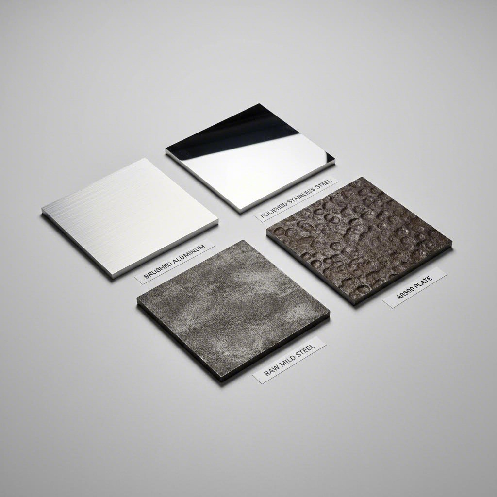
Различните метали — алуминий, стомана и специални сплави — имат уникални характеристики относно топлопроводност, отражателна способност и твърдост, които определят коя технология за рязане дава най-добрите резултати. Влакнените лазери се отличават при рязане на отразяващи метали като алюминиеви листове тъй като техната дължина на вълната се абсорбира ефективно от тези материали. Плазменото рязане обработва по-дебели стоманени плочи икономично, докато водната струя остава предпочитаният метод за топлочувствителни материали или изключително твърди сплави.
При проектиране за неръждаема стоманена ламарина трябва да се има предвид склонността на материала към упрочняване при пластична деформация по време на рязане. Тази характеристика, особено изразена при аустенитни марки като неръждаема стомана 316, означава, че проектът ви трябва да минимизира броя на пробивните точки и да избягва елементи, които изискват режещата глава да остане неподвижна на едно място. При галванизирана ламарина имайте предвид, че цинковото покритие може да произвежда допълнителни изпарения и може да повлияе по различен начин върху качеството на ръба в сравнение с необработената стомана.
Как металните свойства формират избора ви за дизайн
Топлопроводността силно влияе върху начина, по който топлината се разсейва от зоната на рязане. Алуминият провежда топлина приблизително пет пъти по-добре от неръждаемата стомана, което звучи благоприятно, но всъщност създава предизвикателства. Бързото разсейване на топлината означава, че са необходими по-високи настройки на мощността, за да се осигури чисто рязане, а сложните дизайни с плътно разположени елементи може да изпитват проблеми с натрупването на топлина, въпреки добрата топлопроводност на материала.
Твърдостта представлява друго критично съображение. Платата от стомана AR500, с твърдост по Бринел в диапазона от 450 до 510, изисква специализирани подходи. Според MD Metals , рязането с водна струя често се препоръчва за AR500, тъй като студената природа на този метод запазва цялостта на платата, без да повлияе върху нейната твърдост. Конвенционалните термични методи за рязане могат да компрометират термичната обработка, която придава на тази износостойка стомана нейните забележителни свойства.
Имайте предвид следните принципи за проектиране, специфични за материала:
- Алуминий: Позволете по-голямо разстояние между сложните елементи, за да се предотврати натрупването на топлина; проектирайте за по-бързи скорости на рязане
- Неръжавееща оцел: Минимизирайте остри вътрешни ъгли, които създават точки на напрежение; имайте предвид малко по-широки ширини на рязане
- Мека стомана: Най-толерантен материал; подходящ за сложни конструкции с тесни допуски
- AR500: Избягвайте радиуси на огъване, по-малки от препоръчаните от производителя; предпочитайте водна струя за прецизни работи
| Вид материал | Препоръчителен метод за рязане | Максимална дебелина | Разсъждения за дизайна | Общи приложения |
|---|---|---|---|---|
| Алуминиев лист | Влакнест лазер, Водна струя | 25 мм (влакнест лазер при 6 кW+) | Високата отразяваща способност изисква дължина на вълната на влакното; отличното отвеждане на топлината позволява по-високи скорости; склонност към образуване на задръжки от изходната страна | Електронни кутии, аерокосмически компоненти, декоративни панели, радиатори |
| Лист от неръждаема стомана | Влакнест лазер, Водна струя | 25 мм (файбър лазер); практически неограничено (водна струя) | Склонност към упрочняване при обработка; минимизиране на точките за пробиване; азот като помощен газ осигурява ръбове, свободни от оксиди, подходящи за заваряване | Медицински устройства, оборудване за преработка на храни, морски фурнитури, архитектурни елементи |
| Стоманени плочи (мека стомана) | Файбър лазер, плазма, водна струя | 50 мм и повече (плазма); 25 мм (файбър лазер при мощност 6 кВт и по-висока) | Най-търпимият материал за сложни конструкции; кислородът като помощен газ увеличава скоростта на рязане при по-дебелите секции; имайте предвид необходимостта от премахване на окаляване | Структурни компоненти, рамки на машини, автомобилни шасита, обща металообработка |
| AR500 (устойчива на абразивно износване) | Водна струя (предпочитана), плазма | 50 мм (водна струя); 25 мм (плазма с внимание) | Топлинното рязане може да повлияе на твърдостта; избягвайте малки радиуси на огъване, за да се предотврати пукане; водната струя запазва свойствата на материала | Плочи за износ при минно оборудване, балистична броня, компоненти за транспортьори, щитове с висока устойчивост на удар |
Изборът на материал оказва влияние върху всяко следващо проектно решение. Избирането на алуминиев лист за лека скоба означава проектиране спрямо ширината на реза и отчитане на топлинното му поведение. Избирането на неръждаема стомана за хранителен компонент изисква разбиране как азотният помощен газ влияе на качеството на ръба. Тези специфични за материала аспекти стават втора природа с набран опит, но тяхното ясно дефиниране от самото начало предотвратява скъпи грешки по време на реални производствени серии.
Минимални размери на елементи и насоки за допуски
Значи сте избрали Вашия материал и метод на рязане сега идва въпросът, който разделя успешните проекти от отхвърлените файлове: колко малки могат да бъдат вашите елементи всъщност? За разлика от други творчески дисциплини, при които можете свободно да избутвате границите, проектите за рязане на метал изискват спазване на конкретни числови граници. Ако нарушите тези минимални стойности, ще получите непълни резове, деформирани елементи или части, които просто не функционират както е предвидено.
Критични размери, които всеки дизайнер трябва да знае
Преди да преминете към конкретните числа, трябва да разберете защо съществуват тези минимални стойности. Когато лазерен лъч или плазмена дъга преминават през метал, те не създават математически перфектна линия. Вместо това те отстраняват тънък канал от материал, известен като „керф“ (ширина на реза). Според SendCutSend ширината на реза при влакнен лазер обикновено варира от 0,006" до 0,040" (0,152 мм до 1 мм), в зависимост от дебелината на материала, докато при CO₂ лазер ширината на реза е между 0,010" и 0,020" (0,254 мм до 0,508 мм).
Тази ширина на реза директно определя минималните ви размери на елементите. Всеки детайл, по-малък от ширината на реза, просто не може да съществува в готовата част, тъй като процесът на рязане консумира повече материал, отколкото съдържа самият елемент. Затова разбирането на характеристиките на реза за избраната ви технология за рязане е основата на правилното проектиране.
Консултирането с таблица за дебелина на листов метал става задължително при превръщането на проектната ви идея в изпълними производствени спецификации. Ето един важен уточняващ момент: номерата на дебелините („гейдж“) не са еднакви за различните материали. Както MakerVerse обяснява, лист с дебелина 16 гейдж не означава едно и също нещо за алуминий и за стомана. Системата за дебелина е възникнала като производствено съкращение през XIX век, където по-малките числа указват по-дебели листове, но за различните материали се използват напълно различни скали.
За практическа справка, дебелината на стоманен лист с калибър 14 е приблизително 1,9 мм (0,075″), докато дебелината на стоманен лист с калибър 11 е около 3,0 мм (0,120″). Тези стойности за дебелина директно влияят върху изчисляването на вашите минимални характеристики, тъй като по-дебелите материали обикновено изискват пропорционално по-големи минимални характеристики.
Правила за минимален размер на характеристики според дебелината на материала
Връзката между дебелината на материала и минималния диаметър на отвора следва предсказуеми закономерности, макар конкретните съотношения да се различават в зависимост от типа материал. Справочните данни от ADS Laser Cutting предоставят конкретни минимални стойности за често срещани материали:
| Дебелина на материала | Мека стомана (минимален отвор) | Неръждаема стомана (минимален отвор) | Алуминий (минимален отвор) |
|---|---|---|---|
| 1,0 мм | 0,50 mm | 0,50 mm | 1,00 mm |
| 2,0 мм | 1,00 mm | 1,00 mm | 1,50 mm |
| 3,0 мм (≈ калибър 11) | 1,00 mm | 1,00 mm | 2,00 mm |
| 6.0мм | 3.00mm | 1,00 mm | 4.00mm |
| 10.0мм | 5.00мм | 1,00 mm | 7,00 мм |
| 20,0 мм | 10.00mm | 2,50 mm | 13.00мм |
Обърнете внимание как алуминият постоянно изисква по-големи минимални отвори в сравнение със стоманата при еднаква дебелина. Това отразява топлинното поведение на алуминия и начина, по който топлината се разсейва бързо от зоната на рязане. Интересно е, че неръждаемата стомана поддържа изключително постоянни минимални размери на отворите дори при увеличаване на дебелината, което я прави отличен избор за конструкции, изискващи малки елементи в по-дебели материали.
Освен диаметрите на отворите, прилагайте тези основни насоки за минимални елементи при използване на таблица за размери на щифтове при проектирането на вашите изделия:
- Съотношение на минималния диаметър на отвора: Като общо правило диаметърът на отвора трябва да е равен или по-голям от дебелината на материала. За прецизни работи използвайте материално-специфичните стойности по-горе.
- Минимална ширина на процеп: Прорезите трябва да са поне 1,5 пъти по-широка от дебелината на материала. По-тесните прорези са изложени на риск от непълно изрязване и деформация на материала.
- Разстояние между ръбовете: Запазете поне 1,0–1,5 пъти дебелината на материала между съседни елементи, за да се предотврати топлинното свързване и структурната слабост.
- Разстояние от ръба до отвор: Функциите трябва да са на разстояние най-малко 1,0 пъти дебелината на материала от всеки външен ръб, за да се запази структурната цялостност.
- Размери на табулаторното съединение: За части, изискващи табулатори при рязане, размерът на табулаторите трябва да е поне 2,0 пъти дебелината на материала по ширина и 0,5 пъти дебелината по дължина.
- Минимален вътрешен ъглов радиус: Вътрешните ъгли трябва да имат радиус поне 0,5 мм, за да може режещата глава да се движи без прекомерно задържане.
Разбиране на керфа и методите за компенсация
Точността на лазерното рязане силно зависи от правилното управление на керфа. Керфът не е просто ширината на премахнатия материал; той варира в зависимост от геометрията на рязане, налягането на помощния газ, мощното на лъча и свойствата на материала. Поради тази променливост съвременните производствени услуги автоматично управляват компенсацията на керфа, вместо да изискват ръчно коригиране на файловете от проектантите.
Въпреки това, разбирането на ширината на рязане все още е важно за проектните решения. Когато две линии за рязане вървят успоредно и близо една до друга, комбинираната ширина на рязане от двете резения може да остави преградни участъци по-тънки от предвиденото. Ако във вашия проект има 2 мм преграда между два изрязани отвора, а всяко рязане премахва 0,3 мм ширина на рязане, действителната ширина на преградата ще бъде приблизително 1,4 мм. При конструкции с носеща функция тази разлика има голямо значение.
Професионалният софтуер за производство прилага компенсация на ширината на рязане, като измества линията за рязане от всяка страна на проектната ви линия. За външни контури изместването е навън, за да се запазят предвидените размери. За вътрешни елементи като отвори, изместването е навътре. Това се случва автоматично, но трябва да проектирате с оглед на тези корекции:
- Сложни модели: Елементи с размери под 0,008" до 0,040" (в зависимост от процеса и материала) могат напълно да бъдат загубени поради консумация от ширината на рязане.
- Вложени части: При рязане на части, които се сглобяват, трябва да се отчете ширината на реза (kerf) върху двете съединяващи се повърхнини, за да се постигне правилният люфт или плътна посадка.
- Текст и фини детайли: Минималната ширина на щриховете за четлив текст трябва да надвишава два пъти ширината на реза; в противен случай знаците ще се размият или изчезнат.
Допусната грешка при лазерно рязане, която можете да постигнете, зависи от последователното спазване на тези размерни указания. Частите, проектирани в рамките на тези параметри, пристигат от производството готови за употреба, докато проекти, които надхвърлят тези граници, често изискват вторични операции или напълно ново проектиране. С установяването на тези числени основи, следващото предизвикателство за вас е подготовката на файлове, които точно предават тези спецификации на производственото оборудване.
Формати на файлове и стандарти за подготовка
Вие сте определили точните размери и сте избрали идеалния материал. Но тук много перспективни проекти спират: самият файл. Изпращането на файл в неподходящ формат или на файл, пълен с крилати грешки, може да забави производството с дни или да доведе до детайли, които изобщо не приличат на вашия дизайн. Разбирането на изискванията към форматите на файловете превръща вас от човек, който създава дизайн, в човек, който подава файлове, готови за производство.
Избор на подходящия файлов формат за вашия проект
Три файлови формата доминират в областта на рязането на метали и всеки от тях има специфична роля във вашия работен процес. Правилният избор зависи от сложността на вашия дизайн, от използваното фабрикационно оборудване и от степента на контрол, който искате да имате върху процеса на рязане.
DXF (Drawing Exchange Format) се счита за индустриален работен кон. Според DXF4You почти всички CNC машини и дизайн програми могат да отварят, четат и обработват файлове във формат DXF, което прави този формат стандарт в индустрията за приложения, свързани с рязане на метали. Този формат съхранява векторна информация, която машините използват, за да насочват режещите инструменти по прецизни траектории. Независимо дали използвате лазерен рязач, плазмена система или водна струя, DXF осигурява надеждна крос-платформена съвместимост, която опростява сътрудничеството между дизайнерите и производителите.
SVG (Scalable Vector Graphics) е особено подходящ за уеб-базирани дизайн работни процеси и по-прости проекти. Много идеи за лазерно рязане започват като файлове във формат SVG, тъй като те лесно се създават с безплатни софтуерни решения и запазват идеална мащабируемост. Въпреки това файловете във формат SVG често изискват конвертиране, преди промишлените CNC устройства да могат да ги обработят, а също така не поддържат възможностите за организация по слоеве, които са необходими за по-сложни проекти.
G-код представлява езика на машинното ниво, който CNC оборудването всъщност изпълнява. Макар обикновено да не създавате G-код директно, разбирането на неговата роля ви помага да оцените защо правилната подготвка на файловете има значение. Вашият DXF или SVG файл се преобразува в инструкции на G-код, които точно указват на машината къде да се движи, кога да активира лазера или плазмения резак и с каква скорост да работи през всяка операция.
| Формат | Най-добър случай за употреба | Преимущества | Ограничения |
|---|---|---|---|
| DXF | Професионално производство, сложни промишлени части | Универсална съвместимост, поддръжка на слоеве, прецизен контрол върху размерите | По-големи размери на файловете, изисква знания за CAD софтуер |
| SVG | Прости проекти, хобистки проекти, уеб-базирани работни процеси | Безплатна поддръжка на софтуер, съвместимост с уеб, лесно редактиране | Ограничена организация на слоевете, може да се наложи конвертиране за използване с CNC |
| G-код | Директно управление на машината, специализирани операции | Максимален контрол върху параметрите на рязането, оптимизация, специфична за машината | Формат, специфичен за машината, изисква знания за постобработка |
За повечето идеи за лазерна рязка и професионални приложения, DXF остава най-безопасният избор. Както се посочва в насоките на производствената индустрия, когато използвате софтуер като CorelDraw или Inkscape, трябва да експортирате дизайна си като AI или DXF с милиметрови единици и само контури, преди да го подадете, за да се осигури максимална съвместимост.
Контролен списък за подготовката на файловете преди подаване
Дори и най-добрият софтуер за дизайн при лазерна рязка не може да предотврати човешки грешки по време на подготовката на файловете. Следването на системен работен процес позволява откриването на проблеми, преди те да доведат до скъпоструващи забавяния в производството. Ето пълния стъпка по стъпка процес от концепцията до готовите за подаване файлове:
- Създайте своя дизайн, използвайки векторна геометрия. Независимо дали работите с Adobe Illustrator, CorelDraw, AutoCAD или специализиран софтуер за дизайн за лазерна рязка като xTool Creative Space, уверете се, че всяка режеща пътека се състои от истински вектори, а не от растерни изображения. Растерната графика работи за гравиране, но не може да дефинира режещи пътеки.
- Преобразувайте целия текст в контури или пътища. Лазерните рязачни машини не могат директно да обработват активни текстови полета. Преобразуването на текста в форми осигурява той да се появи точно както е проектиран, независимо от това какви шрифтове са инсталирани у изпълнителя.
- Организирайте елементите чрез правилното използване на слоеве. Разделете пътищата за рязане от тези за гравиране или маркиране, като използвате отделни слоеве. Този подход със слоевете помага на машината правилно да интерпретира проекта ви и намалява риска от грешки по време на производството.
- Почистете припокриващата се и дублирана геометрия. Припокриващи се линии карят машината да реже един и същ път няколко пъти, което губи време и потенциално поврежда материала. Използвайте инструментите за почистване във вашия софтуер, за да премахнете дубликати и обедините съвпадащи крайни точки.
- Проверете видовете и широчините на линиите. Линиите имат конкретно значение за софтуера за рязане. Според xTOOL , широчината на линията показва дали машината трябва да реже, гравира или чертае. Широчина на линия от 0,2 pt може да означава рязане, докато по-дебели линии, например 1 pt, могат да обозначават области за гравиране.
- Проверете размерите и точността на мащаба. Потвърдете, че вашето проектно решение използва правилната мерна единица (милиметри срещу инчове) и че всички размери съответстват на предвидените размери на детайлите. Грешките при мащабиране между различните софтуерни системи водят до отхвърляне на по-голям брой детайли, отколкото почти всяка друга причина.
- Приложете подходящо подреждане и разстояния. Поставете детайлите на поне 2 мм разстояние един от друг, за да се избегне изгаряне или слепване на резовете. Оставете минимална маргина от 5 мм от краищата на материала, за да се компенсира износът по ръбовете и допустимите отклонения при позициониране.
- Изпълнете симулация или преглед, ако е налична такава възможност. Много CNC софтуерни програми предлагат инструменти за симулация, които визуализират траекторията на рязане преди производството. Този етап позволява да се идентифицират потенциални проблеми, като например неправилни траектории на инструмента, преди да започне обработката на реален материал.
- Експортирайте с правилни настройки на формата. При експортиране на файлове DXF изберете подходяща версия за съвместимост (форматите R14 или 2000 предлагат най-широката поддръжка) и уверете се, че мерните единици съответстват на изискванията на вашия производител. Проверете дали цялата геометрия се експортира като полилинии или контури, а не като блокове или препратки.
- Документирайте ясно специалните изисквания. Маркирайте типа материал, дебелината и количествените изисквания вътре в файла, като използвате слой за бележки, или в придружаващата документация. Ясната комуникация предотвратява допускането на предположения, които водят до неправилно производство.
Често срещани грешки във файловете, които причиняват забавяне на производството, включват незатворени контури (когато линиите за рязане не образуват пълни фигури), самопресичаща се геометрия, изключително кратки отсечки, които объркват генерирането на траекторията на инструмента, и вградени растерни изображения, които са били погрешно разпознати като контури за рязане. Повечето софтуерни решения за проектиране за лазерно рязане включват инструменти за проверка, които откриват тези проблеми преди експортирането.
При проектирането за лазерно рязане имайте предвид, че пълненето и линиите служат за различни цели. Линиите определят точните траектории за рязане, които машината следва точно, докато запълнените области показват зони за гравиране, при които лазерът премахва материал в няколко прохода. Прибъркването на тези елементи води до гравиране там, където трябва да има пробиване или обратното.
Подготовката на вашите файлове директно влияе както върху скоростта на производството, така и върху качеството на детайлите. Чистият и правилно форматиран файл преминава през опашката за изработка без забавяне, докато проблемните файлове изискват обратна връзка, която удължава сроковете за изпълнение. Когато вашите файлове са правилно подготвени, следващото нещо, което трябва да се има предвид, е как тези изрязани детайли всъщност ще се събират в крайното приложение.
Проектиране за сглобяване и интеграция
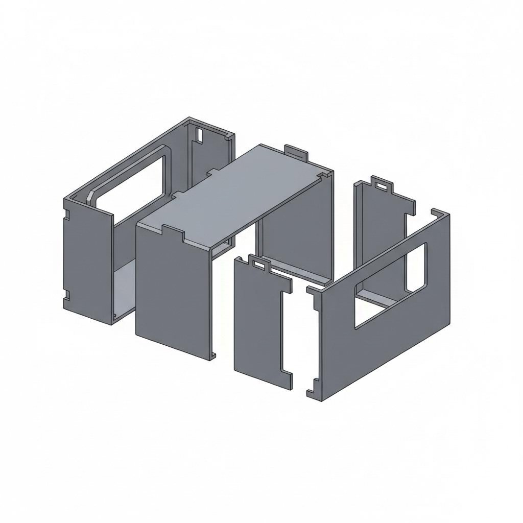
Вашите части, изрязани с лазер, изглеждат перфектни върху масата за рязане. Но ето реалността: тези отделни компоненти все още трябва да бъдат сглобени в функционална конструкция. Независимо дали изграждате корпус за електроника или произвеждате структурни скоби, начина, по който проектирате за сглобяване, определя дали частите ще се съединят лесно и без усилие или ще се наложи часове работа с шлифовъчна машина, подлагане на допълнителни прокладки и разочарование.
Проектиране на части, които се съчетават идеално
Най-елегантните проекти за рязане на метал предвиждат сглобяването още от първия набросък. Вместо да разглеждат производството и сглобяването като отделни аспекти, опитните проектиранти интегрират елементите за свързване директно в своите плоски чертежи. Този подход елиминира необходимостта от приблизително подравняване, намалява изискванията към фиксиращите устройства и създава конструкции, които практически се сглобяват сами.
Според Fictiv добре проектирани самонасочващи се компоненти като езици и процепи могат да намалят времето за настройка на приспособленията с 40–60% при производство в малки до средни серии. Тези зацепващи се елементи действат като вградени ориентири, осигурявайки последователност на междинните разстояния между детайлите в рамките на ±0,2 мм, като елиминират необходимостта от външни шаблони.
При проектирането на връзки с езици и процепи следвайте тези проверени насоки:
- Ширина на езика: Размерът на езиците трябва да бъде най-малко 1,5 до 2 пъти дебелината на материала, за да се осигури достатъчна якост на съединението
- Зазор за процеп: Прилагайте зазор 0,05–0,1 мм от всяка страна за лазерно изрязани части, които изискват сглобяване чрез плътна посадка
- Дължина на езика: Езиците трябва да имат дължина поне равна на дебелината на материала, за да осигурят достатъчна дълбочина на въвеждане
- Закръгляне на ъглите: Добавете радиус на закръгляне 0,5–1 мм във вътрешните ъгли на процепите, за да се съобразите с геометрията на режещия инструмент
- Компенсация за широчина на реза (kerf): Имайте предвид, че пазовете, нарязани номинално, може да се нуждаят от разширяване с половината ширина на рязането от всяка страна за прецизни поставяния
Предвиждането за монтиране на фурнитура изисква подобно предварително планиране. Ако във вашия дизайн са необходими нарязани връзки, но материалът е твърде тънък за нарезаване, обмислете пробойни с размери за фурнитура с преширок или заклепки. Като говорим за заклепки, те предлагат отлична икономична алтернатива на болтовите връзки, особено при съединяване на по-тънки материали, където техната икономия на брой и устойчивост към вибрации се оказват предимство.
Функции, готови за сглобяване, във вашите файлове за рязане
Различните методи за сглобяване налагат различни изисквания към вашия дизайн. Изборът на правилния подход зависи от изискванията ви за допуски, обема на производството и дали сглобяването изисква последващо разглобяване.
| Метод за монтаж | Изисквания за допуск | Сложността на дизайна | Най-добри приложения |
|---|---|---|---|
| Език и процеп | ±0,1–0,2 мм зазор между пазовете от всяка страна; осигурява центриране на детайлите в рамките на ±0,2 мм по време на заваряване | Средно – изисква внимателно планиране на геометрията, но използва стандартни операции за рязане | Заварени кутии, самонасочващи сглобки, прототипни рамки, модулни продукти, изискващи демонтаж без инструменти |
| Фиксиране с фитинги | Отвори за преминаване според стандарта ASME 18.2.8; обикновено с размер 0,4-0,8 мм по-голям от диаметъра на здраво съединение | Ниско - стандартни шаблони за отвори с лесно достъпни фиксатори | Подлежащи на сервизиране сглобки, регулируеми връзки, съединяване на различни материали, високопрочни структурни връзки |
| Заварена сглобка | толерантност на междинен отвор 0,1-0,15 мм от всяка страна за компенсация на свиване при заваряване | Средно до високо - изисква подготовка за заваряване и планиране на топлинна деформация | Постоянни структурни съединения, водонепропускливи кутии, приложения при висока температура, носещи рамки |
| Блокиращи конструкции | Пресоващата посадка изисква интерференция от 0,05–0,1 мм; посадката с люфт позволява зазор от 0,1–0,3 мм | Високо — пъзелоподобната геометрия изисква прецизно изчисляване на съвпадащите елементи | Сглобяване без инструменти, декоративни изделия, опаковки, временни прототипи, витрини, които изискват многократно разглобяване |
При заваряваните сглобки вашето проектиране трябва да взема предвид топлинните ефекти не само в самото съединение. Fictiv препоръчва редуване на местата за точково заваряване (например, таб 1 и таб 3, след това таб 2 и таб 4), за да се балансират топлинните напрежения и да се минимизира деформацията. Избягвайте прекалено големи пази, които водят до тънки заваръчни участъци или задържане на разтопен метал по време на процеса на заваряване.
Заваряването на алуминий представлява специфични предизвикателства поради високата топлопроводност на материала и образуването на оксиден слой. При проектирането на алуминиеви части, предназначени за заваряване, включете по-големи табови елементи, които осигуряват адекватно отвеждане на топлината и гарантират достатъчно количество материал след термичната деформация.
Съображения при огъване за формовани сглобки
Много сглобки комбинират плоско лазерно рязане с последващи операции по огъване. Тази комбинация от лазерно рязане и огъване създава тримерни форми от двумерни плоски шаблони, но успехът зависи от разбирането как огъването влияе върху цялостния ви дизайн.
При огъване на листов метал материала се удължава по външната повърхност и се компресира по вътрешната повърхност. Според стандарта за одобрен листов метал изчисляването на допуска за огъване определя колко допълнителна дължина на материала е необходима в плоския шаблон, за да се постигнат правилните окончателни размери след формоването.
Коефициентът K, който обикновено варира между 0,3 и 0,5 за повечето приложения с листов метал, показва положението на неутралната ос в дебелината на материала по време на огъване. Тази стойност директно влияе върху изчисленията на плоския шаблон:
- Поправка за огъване: Дължината на дъгата на неутралната ос при огъване, добавена към дължините на рамената, за определяне на размера на плоския шаблон
- Намаление при огъване: Количеството, което се изважда от желания размер на детайла, за да се компенсира разтягането на материала по време на огъване
- Вътрешно отстъпване: Разстоянието от вътрешния връх на огъва до мястото, където съседните фланци могат да легнат плоско и без зазор
- Минимален радиус на огъване: Обикновено 1–2 пъти дебелината на материала; по-малките радиуси носят риск от пукнатини, особено при по-твърди материали
За операции по лазерно рязане на равни заготовки, които предшестват огъването, позиционирайте отвори и други елементи на разстояние от линиите на огъване. Елементи, разположени твърде близо до линиите на огъване, ще се деформират по време на формирането на детайла, което може да доведе до удължаване на отворите или преместване на техните положения спрямо други елементи за сглобяване. Безопасно практическо правило гласи, че всички елементи трябва да са на разстояние поне 2–3 пъти дебелината на материала от всяка линия на огъване.
Имайте предвид и как последователността на огъванията влияе върху достъпа за сглобяване. Например скоба, която се огъва в U-образна форма, може да „затвори“ точките за монтиране на крепежни елементи вътре в нея, ако не планирате внимателно последователността на формирането. Конструирайте своята равна заготовка така, че след всяко последователно огъване всички места за монтиране на крепежни елементи, ориентиращи елементи и повърхности за съчетаване да остават достъпни.
Взаимодействието между точността на рязането и точността на огъването определя крайната пригодност на сглобяването ви. Дори идеално изрязаните части могат да доведат до неправилно подравнени сглобки, ако поправките за огъване не са изчислени коректно за конкретния ви материал и инструменти. Когато вашите проекти стават по-сложни, балансирането на тези аспекти става втора природа, но основният принцип остава неизменен: всяко проектно решение трябва да предвижда начина, по който отделните части ще функционират заедно като единна сглобка.
Декоративни срещу индустриални подходи в дизайна
Представете си, че проектирате изящна градинска порта с извити орнаменти. Сега представете си, че проектирате крепежна скоба за подвеска, която трябва да издържа хиляди цикъла на натоварване. И двете задачи включват проектиране на метални части за рязане, но приоритетите им не могат да бъдат по-различни. Разбирането кога естетиката е водещ фактор, а кога доминират инженерните изисквания, ви помага да подхождате към всеки проект с правилния мисловен модел от самото начало.
Художествени проекти срещу индустриални спецификации
Декоративните приложения поставят визуалният ефект над всичко останало. При създаването на метални дизайн-елементи, изрязани с лазер, за стенни декорации, табелки или архитектурни елементи, основните ви ограничения са свързани с външния вид, ефектите от сенките и начина, по който светлината взаимодейства с изрязаните шарки. Структурната цялост има значение само дотолкова, доколкото предотвратява разпадането на елемента по време на обработка и монтаж.
Персонализираните метални табелки са ярък пример за този подход, насочен първо и преди всичко към естетиката. Вашите дизайн-решения се фокусират върху четливостта, представянето на бранда и визуалната йерархия, а не върху носимата способност. Сложни филигранны шарки, които биха били структурно рисковани при машинни компоненти, стават напълно уместни, когато единствената функция на детайла е да изглежда красиво на стена.
Промишлените спецификации напълно обръщат тези приоритети. Компонент за монтиране на шасито или за подвеска трябва да издържи многократни цикли на механично напрежение, термично разширение, вибрации и въздействие на околната среда. Външният вид става второстепенен по отношение на функционалността, а всяко проектно решение трябва да отговаря на въпроса: „Ще компрометира ли тази характеристика конструктивната устойчивост?“
Проектните приоритети за декоративни и художествени приложения включват:
- Визуална сложност: Изискани орнаменти, фини детайли и сложни негативни пространства създават визуален интерес и дълбочина на сенките
- Качество на ръба: Гладките ръбове, свободни от заострени ръбове (зъбчета), имат значение както за външния вид, така и за безопасното обращение в изложбени среди
- Плътност на шаблона: Колко материал трябва да бъде премахнат, за да се постигне желаният ефект на прозрачност и светлопропускливост
- Съотношения на мащаба: Пропорциите между позитивното и негативното пространство, които се възприемат добре на предвиденото разстояние за наблюдение
- Съвместимост с повърхностната обработка: Проектни характеристики, които добре приемат боядисване, напръскване с прахови покрития или патиниране
- Предпазни за монтаж: Скрити точки за монтиране, които не нарушават визуалния дизайн
Дизайн приоритети за индустриални и функционални приложения включват:
- Непрекъснатост на натоварването: Разпределение на материала, което ефективно предава сили без концентрация на напрежения
- Устойчивост към умора: Просторни ъгли и гладки преходи, които предотвратяват образуването на пукнатини при циклично натоварване
- Размерна стабилност: Елементи, които запазват критичните допуски въпреки термично разширяване и механично напрежение
- Оптимизация на теглото: Стратегическо премахване на материал, което намалява масата, без да компрометира якостта спрямо теглото
- Точност на сглобяемите повърхности: Отвори за монтиране и съединяващи повърхности със стеснени допуски за надеждна поставяне
- Достъп за обслужване: Конструктивна геометрия, която позволява инспекция, поддръжка и замяна на компоненти
Когато естетиката среща инженерните изисквания
Някои проекти не могат да бъдат категоризирани ясно в нито една от двете категории. Архитектурната метална обработка често изисква както визуална елегантност, така и структурна устойчивост. Декоративната перила трябва да изглеждат впечатляващо, но същевременно да издържат безопасно човешката тежест. Тези хибридни приложения изискват първо да бъдат изпълнени минималните инженерни изисквания, а след това — оптимизиране на външния вид в рамките на тези ограничения.
За дизайн на метални детайли, изработвани чрез лазерно рязане, който обединява двете области, започнете с определяне на непроменяемите структурни изисквания. Определете минималната дебелина на материала, максималната дължина на разстоянието между опорите и необходимите коефициенти на сигурност, базирани на товарните условия на приложението. Едва след като тези параметри са фиксирани, можете да проучите декоративните възможности в оставащото проектно пространство.
Помислете как проектирането за лазерно рязане на магнитни приложения илюстрира това равновесие. Декоративните хладилни магнити поставят акцент върху сложни шарки и визуална привлекателност, докато промишлените магнитни фиксатори изискват прецизни размери и здрава геометрия. Технологията за рязане остава една и съща, но философията на проектирането напълно се различава в зависимост от изискванията на крайното приложение.
Библиотеките с шарки и шаблоните могат да ускорят както декоративните, така и промишлените проектиране. Услуги като ez laser designs предлагат предварително подготвени шарки, които отговарят на естетичните изисквания, освобождавайки ви да се съсредоточите върху адаптирането на тези елементи към конкретните ви материали и размерни изисквания. Винаги обаче трябва да се има предвид, че декоративна шарка не може да се прилага директно за структурни приложения без инженерна валидация.
Сладката точка за дизайните за лазерно рязане на метал често се намира в функционалното изкуство: предмети, които изпълняват практическа цел, но същевременно осигуряват и визуално удовлетворение. Персонализирана скоба с елегантни пропорции. Защитна решетка за машина с вкусно изпълнени вентилационни шарки. Конструктивна подпора с фасетирани ръбове и закръглени ъгли, която случайно изглежда изтънчена. Тези дизайните са успешни, защото разглеждат естетиката като допълнителен елемент, постигнат в рамките на инженерните ограничения, а не като цел, която компрометира функционалността.
Независимо дали следващият ви проект поставя акцент върху естетиката, издръжливостта или и двете, яснотата относно тези различия предотвратява скъпоструващи несъответствия между замисъла на дизайна и крайния резултат. Декоративната работа допуска структурна неефективност в името на визуалните цели. Промишлената работа изисква структурна адекватност независимо от външния вид. Знанието коя гледна точка да приложите осигурява подходящи проекти за предвидената цел и ви спасява от разочарованието от части, които изглеждат перфектно, но се провалят при употреба, или работят безупречно, но разочароват естетически.
Чести грешки в дизайна и как да ги избегнем
Следвали сте правилата за рязане, избрали сте подходящи материали и внимателно сте подготвили файловете си. Въпреки това някак си частите все още напускат масата с проблеми. Познато ли ви звучи? Дори и опитни дизайнери се сблъскват с производствени проблеми, които се дължат на предотвратими проектирани решения. Разбирането на тези чести капани преди да изчерпят бюджета ви за материали превръща досадните изненади в предвидими и избягвани резултати.
Грешки, които прахосват материал и време
Лазерното рязане е изключително прецизно, но не може да компенсира фундаментални проектирани грешки. Според анализ на индустрията за обработване , повечето производствени повреди идват от няколко често срещани грешки, които конструкторите повтарят отново и отново. Ето най-честите грешки при проектирането и техните решения:
- Недостатъчни радиуси на ъглите: Остри вътрешни ъгли създават точки на концентрация на напрежение и принуждават рязещата глава рязко да забави ход. Това задържане причинява прекомерно натрупване на топлина, което води до лошо качество на ръба и потенциално повреждане на материала. Решение: Добавете минимален вътрешен радиус от 0,5 мм към всички ъгли, увеличавайки до 1–2 мм за по-дебели материали или приложения с високо напрежение.
- Неправилно подреждане и натрупване на топлина: Рязането на множество части твърде близо една до друга позволява на топлината от съседни резове да се натрупва. Това топлинно натрупване причинява деформация, неточни размери и влошено качество на ръба в цели плочи. Решение: Запазете поне 2 мм разстояние между детайлите и използвайте софтуер за оптимизиране на разположението, който променя местата на рязане, за да се разпредели топлината равномерно по заготовката.
- Игнориране на компенсацията на рязането (kerf): Както отбелязват експертите по производство, лазерът премахва малка част от материала по време на рязане. Ако не се компенсира този разрез, детайлите няма да паснат правилно, особено при сглобяване с шипове и пазове. Решение: Потвърдете дали вашият производител прилага подходящи корекции за ширината на разреза или коригирайте съответстващите елементи с половината ширина на разреза от всяка страна при проектиране на прецизни сглобки.
- Елементи, твърде близо до ръбовете: Отвори, пазове или изрязани участъци, разположени близо до ръбовете на материала, нямат достатъчно поддържащ материал и могат да се деформират по време на рязане или обработка. Решение: Разполагайте всички елементи на поне 1,0 до 1,5 пъти дебелината на материала от всеки външен ръб.
- Твърде сложни геометрии: Конструкциите с прекомерен брой възли, изключително къси отсечки или ненужни подробности забавят обработката и увеличават риска от грешки. Решение: Опростяване на пътищата чрез премахване на излишни точки, преобразуване на малки елементи в по-прости форми и елиминиране на детайли, по-малки от тези, които процесът на рязане може надеждно да възпроизведе.
- Неправилна организация на слоевете: Ако слоевете във файловете с вашето дизайн решение не са зададени правилно, машината може да започне рязането преди гравирането или да изпълни операциите в неправилен ред, което води до проблеми с подравняването и загуба на материали. Решение: Организирайте слоевете логично, като използвате ясни конвенции за именуване, и поставяйте вътрешните елементи преди външните контури в последователността на рязането.
- Пропускане на пробни резове: Прекосяване направо към производството, без предварително тестване на настройките върху пробен образец, води до неочаквани проблеми при работа с ценни материали. Решение: Винаги извършвайте малък пробен рез с идентичен материал и идентични настройки, преди да започнете пълното производствено изпълнение.
Отстраняване на дизайнерски проблеми преди производството
Разбирането на образуването на шлака ви помага да проектирате детайли, които излизат по-чисти след процеса на рязане. Какво точно представлява шлаката? Шлаката се дефинира като претопен метал, който се затвърдява отново и се прилепва към долната ръбна част на материалите, рязани с лазер. Според изследвания за контрол на качеството , шлаката възниква, когато течният материал не бъде изхвърлен чисто от зоната на рязане, а вместо това се затвърдява от долната страна на заготовката.
Макар образуването на шлака да зависи отчасти от настройките на машината и потока на помощния газ, вашите проектиращи решения влияят върху нейната тежест. Детайлите с много пробивни точки, тесни вътрешни елементи или недостатъчно разстояние между тях натрупват повече шлака, тъй като рязащата глава трябва многократно да намали скоростта си. Проектирането на по-гладки рязащи пътища с по-малко промени в посоката намалява образуването на шлака, като осигурява постоянна скорост на рязане през целия процес.
Топлинната деформация представлява друго предизвикателство, което процесите за лазерно рязане на метали могат да въведат. Както обясняват проучванията в областта на топлинния режим, зоните, засегнати от топлина, причиняват неравномерно разширяване и свиване, което води до огъване. Няколко фактора влияят върху степента на деформация:
- Променлива дебелина на материала: Неконсистентната дебелина на суровината създава непредвидимо разпределение на топлината
- Модели на разпределение на топлината: Концентрираното рязане в една област увеличава топлинното напрежение
- Разлики в скоростта на охлаждане: Тънките участъци се охлаждат по-бързо от дебелите области, което създава вътрешни напрежения
- Последователност на рязане: Лошата последователност позволява натрупване на топлина, вместо тя да се разсее
Умното софтуерно решение за подреждане автоматично решава множество проблеми, свързани с деформацията. Съвременните системи анализират геометрията на детайлите и генерират последователности за рязане, които минимизират термичното напрежение чрез алтернативно рязане в различни области на листа. Софтуерът стратегически разполага детайлите и оптимизира пътя на рязащия пламък, за да предотврати натрупването на топлина — особено важно при работа с материали, които се рязат с лазер и са склонни към деформация, като тънки листови метали или алуминий.
Съображенията за безопасност също влияят върху подготовката на вашите файлове. Лошата вентилация по време на рязане води до натрупване на дим, което намалява ефективността на лазера и създава опасни условия. Макар вентилацията да е предимно операционен въпрос, вашето проектиране косвено я засяга. Изключително сложните шаблони с продължително време за рязане генерират повече изпарения в сравнение с по-простите конструкции. Ако вашият проект включва материали със специални изисквания за рязане, документирайте тези изисквания ясно, за да могат операторите съответно да коригират вентилацията и мерките за защита.
Преди да изпратите някой файл за производство, прегледайте този бърз списък за диагностика:
- Всички вътрешни ъгли ли са закръглени подходящо според дебелината на материала?
- Разстоянието между елементите достатъчно ли е, за да се предотврати топлинното мостово свързване?
- Точките за пробиване са ли разположени на разстояние от критичните ръбове, където капките разтопен материал (дрос) могат да повлияят на прилягането?
- Дизайнът позволява ли логична последователност на рязането – от вътрешността към външността?
- Проверили ли сте дали всички елементи надвишават минималните размерни прагове за съответния материал?
- Указан ли е подходящият материал за избраната технология за рязане?
Откриването на тези проблеми по време на фазата на проектиране не струва нищо. Откриването им след рязането води до загуба на материал, време и пари. С добро разбиране на често срещаните грешки и стратегиите за тяхното предотвратяване сте готови да преминете от диагностициране на отделни проблеми към внедряване на пълен, системен работен процес, който осигурява гладко преминаване на вашите проекти от първоначалната идея до завършеното производство.
Пълен работен процес от проектиране до производство
Вие сте овладели основите, избрали материали, задали толеранции и избегнали често срещани грешки. Сега е моментът да видите как всички тези елементи се свързват в един пълен процес – от първоначалната идея до готовата изрязана метална част. Разбирането на този цялостен работен поток превръща отделните знания в повтаряща се система, която осигурява последователни резултати всеки път.
От скица до готова детайл
Всеки успешен проект за производство на ламаринени изделия следва предвидима последователност от етапи. Независимо дали произвеждате единичен прототип или се подготвяте за серийно производство, тези етапи остават непроменени. Разликата между любителски и професионални резултати често се дължи на това колко внимателно е изпълнен всеки етап, преди да се премине към следващия.
Според производствения наръчник на Die-Matic, фазата на проектиране включва съвместна работа на инженери и дизайнери на продукти, за да се гарантира, че компонентите отговарят на изискванията за функционалност, разходи и качество. Този колаборативен подход позволява да се установяват потенциални проблеми на етапа, когато промените все още са евтини за реализиране.
Металообработващата индустрия е претърпяла значителна еволюция в начина, по който проектната концепция се превръща в производствена реалност. Съвременните работни процеси използват цифрови инструменти на всеки етап, като създават документационни следи, които осигуряват съответствие между това, което сте си представили, и това, което получавате от металообработката.
Вашият пълен производствен маршрут
Ето последователния работен процес, който води вашата идея до готови части, изработени чрез лазерно рязане:
- Разработка на концепцията и дефиниране на изискванията. Започнете с уточняване на това, което вашата част трябва да изпълнява. Дефинирайте функционалните изисквания, размерните ограничения, предпочитаните материали и очакваните количества. Като EZG Manufacturing обяснява тази фаза определя целите за размер и тегло, изискванията към материали, критериите за производителност и бюджетните параметри. Документирайте всичко — неясни изисквания водят до несъответстващи резултати.
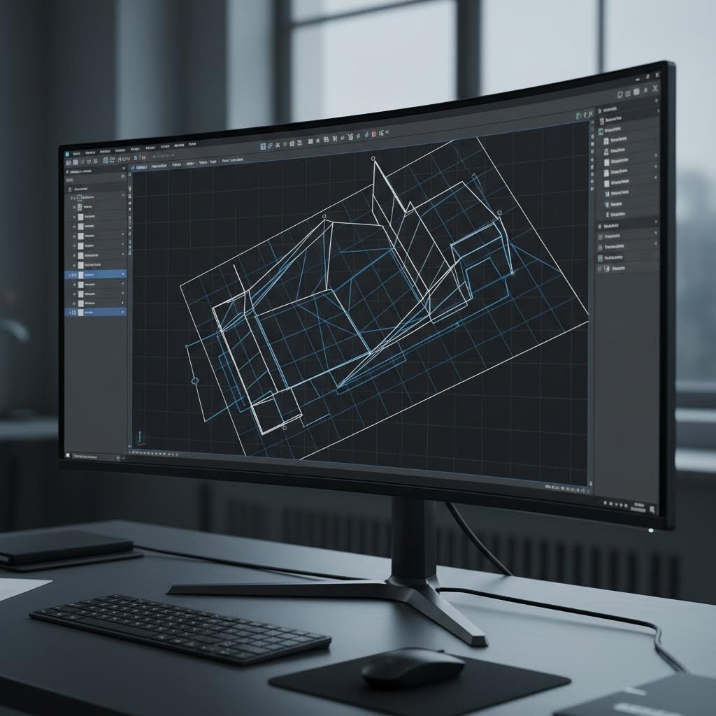
- Първоначално проектиране и CAD моделиране. Превърнете своята концепция в прецизна цифрова геометрия. Създайте 3D модели или 2D профили, използвайки подходящо софтуерно решение за проектиране, като прилагате минималните размери на елементите и насоките за допуски, които бяха разгледани по-рано. Тук разбирането на ограниченията при стоманеното производство дава реална изгода, тъй като ще проектирате в рамките на технологично осъществими параметри от самото начало, а не ще откривате проблеми по-късно.
- Преглед на проекта с оглед на възможностите за производство (DFM). Преди да се ангажирате с производството, нека дизайна ви бъде оценен за ефективността му при производството. Според ръководството на Cadrex за изработка, DFM (проектиране за производствена ефективност) включва преглед на проектите на продуктите, за да се гарантира, че крайните сборки отговарят на желаните резултати и могат да бъдат произведени ефективно. Този преглед разкрива излишни операции по формоване, неподходящи допуски и конструктивни елементи, които увеличават разходите, без да носят функционална полза. Професионални партньори в областта на производството като Shaoyi Metal Technology предлагат комплексна поддръжка за DFM, която идентифицира проектирани проблеми още на ранен етап и предотвратява скъпи корекции след започване на изработката на инструментите.
- Избор на материали и потвърждение на доставката им. Потвърдете, че посоченият от вас материал е наличен в необходимите дебелини и количества. При приложенията с листови стоманени части от неръждаема стомана потвърдете, че конкретният клас отговаря както на функционалните изисквания, така и на съвместимостта с избраната методика за рязане. Времето за доставка на материали може значително да удължи графиките на проектите, затова ранното потвърждение предотвратява забавяния.
- Изработка и валидация на прототип. Преди да се ангажирате с производствени инструменти или големи поръчки на материали, произведете пробни части, за да проверите съвместимостта, функционалността и външния вид. Услугите за бързо прототипиране значително съкращават тази фаза на валидиране. Възможността на Shaoyi за бързо прототипиране за 5 дни ви позволява бързо да получите физически части, да тествате интерфейсите за сглобяване и да потвърдите, че вашето проектиране работи както е предвидено, преди да преминете към мащабно производство.
- Редакция и оптимизация на проекта. Тестването на прототипите почти винаги разкрива възможности за подобрение. Например може да се наложи пренасочване на монтажно отворче, коригиране на радиуса на огъване или промяна на дебелината на материала. Оптимизирайте своя проект въз основа на обратната връзка от физическото тестване и повторно го валидирайте, ако промените са значителни.
- Подготовка на производствените файлове. Генериране на окончателните производствени файлове според формата и стандартите за подготвка, които бяха обсъдени по-рано. Уверете се, че цялата геометрия е чиста, слоевете са правилно организирани и спецификациите са ясно документирани. За части, изрязани с ЧПУ, проверете дали вашите файлове съдържат само векторната информация, необходима за операциите по рязане.
- Изработка на инструменти и приспособления. За производствени количества може да се наложи използването на специализирани инструменти. Прогресивните матрици, формовъчните приспособления и сглобяемите шаблони изискват време за разработка. Според Die-Matic инструментите са от решаващо значение за ефективно и прецизно производство — изборът на подходящи матрици и сътрудничеството с инженерите по проектиране по време на прототипирането потвърждават предвидения производствен процес.
- Изпълнение на производствения цикъл. С валидираните проекти и подготвените инструменти производството продължава чрез операциите по рязане, формоване и довършване, които са необходими за вашите части. Мерките за контрол на качеството по време на тази фаза гарантират последователността на всички произведени части.
- Допълнителна обработка и довършване. Суровите изрязани части често изискват вторични операции: зачистване, за да се премахнат остри ръбове, повърхностни обработки за корозионна защита или операции по сглобяване, при които се комбинират няколко компонента. Планирайте тези стъпки по време на първоначалното проектиране, за да се гарантира, че частите ще пристигнат готови за предвиденото им приложение.
- Инспекция на качеството и документация. Окончателната инспекция потвърждава, че завършените части отговарят на зададените спецификации. Измерителните проверки, визуалната инспекция и функционалното тестване потвърждават успешното производство. За автомобилни приложения, изискващи сертифицирано качество според IATF 16949, тази документация става част от постоянната документация за качество.
- Доставка и интеграция. Завършените части се изпращат до вашето предприятие или директно до местата за сглобяване. Правилното опаковане предотвратява повреди по време на транспортиране, а ясната етикетиране гарантира, че частите ще достигнат предвидените им места без объркване.
Този работен процес се прилага както при поръчване на лазерно изрязани части онлайн за хоби проекти, така и при набавяне на прецизни компоненти за автомобилни шасита и системи за окачване. Разликата се състои в това колко строго се изпълнява и документира всеки етап.
Профессионалният преглед на дизайна за производствена осъществимост (DFM) на етапа на проектиране открива около 70–80 % от потенциалните производствени проблеми, преди да е била изрязана каквато и да е материя, което спестява както време, така и разходи в сравнение с откриването на проблеми по време на производството.
За сложни проекти или производство в големи обеми сътрудничеството с опитни производители опростява целия този процес. Бързината на Shaoyi Metal Technology за предоставяне на комерсиално предложение — само 12 часа — ускорява ранните етапи на проекта и ви осигурява бързо обратно връзка относно осъществимостта и разходите, преди да сте инвестирани значителни ресурси в проектирането. След това техните автоматизирани възможности за масово производство ефективно мащабират вече валидираните проекти, след като прототипирането потвърди вашата проектна цел.
Разликата между концепцията и готовата детайл рязко намалява, когато подходите системно към всеки етап. Бързането през ранните фази, за да се достигне по-бързо до производството, обикновено има обратен ефект и води до цикли на преработване, които отнемат повече време, отколкото би изисквала методична подготовка. Независимо дали сте начинаещ дизайнер или опитен инженер, последователното следване на този план непрекъснато води до по-добри резултати в сравнение с импровизацията по време на процеса на изработване.
След като сте начертали целия работен процес, окончателният ви етап е да съпоставите текущото си ниво на умения с подходящите следващи стъпки и ресурси за продължаващо развитие на възможностите си в проектирането за металообработка.
Превръщане на вашите проекти от концепция в реалност
Вие сте усвоили основните принципи, проучихте материалните аспекти и сте изготвили пълната производствена работна схема. Но накъде оттук? Отговорът напълно зависи от това откъде започвате. Дали чертаете първия си крепежен елемент или оптимизирате сложни сглобки за масово производство – вашите следващи стъпки трябва да съответстват на текущите ви възможности, но едновременно да ви изтеглят към следващото ниво.
Вашите следващи стъпки според нивото на опит
Развитието в областта на проектирането за рязане на метали следва предсказуема прогресия. Всяка стъпка се основава на предишните знания и едновременно с това въвежда нови предизвикателства, които разширяват вашите възможности. По-долу е представен структуриран път, който ви води от основни умения до професионално ниво на компетентност.
Начинаещо ниво: Залагане на основите
- Овладейте един CAD софтуер напълно. Вместо да пробвате множество софтуерни пакети, развийте дълбока професионална компетентност в един-единствен инструмент. Безплатни алтернативи като Fusion 360 или Inkscape предоставят отлични начални точки, без финансови задължения.
- Започнете с прости, еднокомпонентни дизайн-проекти. Създайте основни крепежни скоби, монтажни плочи или декоративни изделия, които включват само операции по рязане — засега без огъване или сложни сглобявания.
- Научете се да четете и прилагате таблица за дебелина на листов метал. Разбирането на конвенциите за дебелина на материала предотвратява скъпи грешки при спецификациите в първите ви поръчки.
- Поръчайте пробни части от онлайн услуги за изработка. Търсете „метална изработка наблизо“ или използвайте онлайн платформи, за да придобиете практически опит как вашите цифрови файлове се превръщат в реални физически части.
- Анализирайте своите грешки. Когато частите не излязат според очакванията, проанализирайте какво е тръгнало наопаки. Дали някои елементи са под минималните размери? Дали допуснатите отклонения са твърде строги? Всяка неуспех учи на нещо ценно.
- Изследвайте възможностите за финиширане. Разбирането на процеси като услуги за напръскване с прах и анодизиране ви помага да проектирате части, които ефективно приемат тези обработки още от самото начало.
Междинно ниво: Разширяване на възможностите ви
- Запознайте се с операциите по гърбене. Проектирайте детайли, които комбинират плоско рязане с оформени елементи. Научете се да изчислявате корекции при гърбене и прилагане на коефициента K за често използваните от вас материали.
- Проектиране на сглобяеми възли от няколко части. Създавайте съединения тип шип-паз, предвиждайте места за монтиране на фурнитура и заключващи се елементи, които се позиционират автоматично при сглобяване.
- Развиване на специализирани познания за конкретни материали. Вместо да третирате всички метали еднакво, разберете как алуминият, неръждаемата стомана и въглеродната стомана се държат по различен начин при операциите по рязане и формоване.
- Построявайте връзки с работилници за обработка в близост до мен. Местни производители на стоманени конструкции и металообработващи работилници в близост до мен често предоставят ценна обратна връзка относно възможността за производство на проекта, която онлайн услуги не могат да осигурят.
- Създавайте шаблони за проектиране. Разработете многократно използвани отправни точки за често срещани типове части — монтажни скоби, панели на кутии, конструкционни ребра, които включват проверени проектни правила.
- Експериментирайте с вторични операции. Научете как анодирането влияе на допуснатите отклонения, как праховото покритие увеличава дебелината на елементите и как тези повърхностни обработки взаимодействат с геометрията на вашия дизайн.
Напреднал уровень: Професионален дизайн
- Оптимизирайте за производствена ефективност. Проектирайте части, които минимизират времето за рязане, намаляват отпадъците от материали чрез интелигентно подреждане и опростяват последващите операции.
- Освободете анализ на натрупване на допуски. Предвиждайте как индивидуалните отклонения на детайлите се натрупват в сборките и проектирайте подходящи зазори, за да гарантирате надеждна сглобяемост.
- Проектирайте за автоматизирано производство. Разберете как вашите проектни решения повлияват на роботизираната обработка, автоматизираното заваряване и процесите за производство в големи серии.
- Развиване на възможности за преглед на приложимостта за производство (DFM). Научете се да оценявате проекти по отношение на техната приложимост за производство преди подаване, за да откривате проблеми, които иначе биха изисквали цикли на преработка.
- Специализирайте се в изискващи приложения. Компоненти за шасита на автомобили, аерокосмически конструкции и медицински устройства всяка една поставя уникални изисквания, които отличават напредналите специалисти от обикновените практикуващи.
- Изграждане на партньорства в производството. Комплексните проекти се възползват от ранно сътрудничество с опитни производители, които могат да предоставят насоки за DFM по време на проектирането, а не след това.
Развиване на уменията ви за проектиране на метална рязка
Напредъкът през тези нива не е строго линеен. Може да се заемете с напреднал анализ на допуснати отклонения за един проект, докато се връщате към изследвания на ниво начинаещ, когато работите с непознат материал. Ключът е постоянното учене чрез практическа работа в комбинация с изучаване на основните принципи.
Според Образователни ресурси на SendCutSend структурирани учебни пътища, които комбинират видеоинструкции с практически проекти, значително ускоряват развитието на уменията в сравнение с подходите, основани единствено на проби и грешки. Серията за колежи по приложни науки на Community College води дизайнерите през основите на CAD, разбирането на процеса на рязане, изчисленията за огъване и операциите по довършване в логична последователност.
Знанието кога да потърсите професионална подкрепа отбелязва прехода от хобист към сериозен практик. Както отбелязва James Manufacturing, професионалните металообработващи фирми следят най-новите индустриални постижения и използват предовременни технологии, за да осигуряват превъзходни резултати. Те могат да ви помогнат да изпълните строгите проектни спецификации, като гарантират постоянство на качеството на продуктите — нещо, което възможностите на собствени производствени мощности често не могат да осигурят.
Помислете за ангажиране на професионална производствена поддръжка, когато вашите проекти включват:
- Тесни допуски, които надхвърлят типичните възможности за изработка
- Материали, изискващи специализирано оборудване за рязане или експертни познания
- Производствени количества, които оправдават инвестициите в инструменти
- Сертификати за качество като IATF 16949 за автомобилни приложения
- Сложни сглобки, изискващи координирани работни процеси с множество операции
- Проекти с критичен срок, при които бързото прототипиране ускорява разработката
За дизайнери, работещи върху автомобилни шасита, окачвания или структурни компоненти, Shaoyi Metal Technology предлага практически ресурс за преминаване от дизайн към производство. Времето за предоставяне на оферта — 12 часа — осигурява бърза обратна връзка относно производимостта и разходите, което ви позволява бързо да подобрите дизайните въз основа на реалните производствени ограничения. Тази оперативност се оказва особено ценна в ранните етапи на проекта, когато дизайн-решенията все още са гъвкави.
Вашият процес на проектиране за рязане на метал не свършва с овладяването на техническите умения. Най-успешните специалисти комбинират техническа компетентност с ясна комуникация, систематично документиране и съвместна работа с производствени партньори. Всеки проект преподава нещо ново, независимо дали става въпрос за поведение на материал, с което не сте се сблъсквали, или за метод на сглобяване, който опростява производството.
Започнете откъдето сте. Използвайте насоките в този ресурс, за да оформите следващия си дизайн. Поръчайте части, оценете резултатите и подобрете подхода си. Разликата между първоначалните опити и работата с професионално качество се намалява по-бързо, отколкото бихте очаквали, ако разглеждате всеки проект едновременно като производствена задача и възможност за учене.
Често задавани въпроси относно дизайна за рязане на метал
1. Какъв е най-добрият начин за рязане на дизайни в метал?
Най-добрата методика за рязане зависи от дебелината на Вашия материал, изискванията към точността и бюджета. Лазерното рязане осигурява изключителна точност при сложни шаблони в материали с тънка до средна дебелина, като например нискоуглеродна стомана, неръждаема стомана и алуминий, като получава гладки ръбове с тесни допуски. Плазменото рязане предлага изгодна по отношение на разходите скорост при по-дебели стоманени плочи, докато водната струя обработва термочувствителни метали и изключително твърди сплави без термично изкривяване. За автомобилни шасита и конструктивни компоненти, които изискват качество, сертифицирано според IATF 16949, производители като Shaoyi Metal Technology предоставят комплексна поддръжка при проектирането за производимост (DFM), за да съпоставят Вашия проект с оптималния метод за рязане.
колко дебела стомана може да нареже 1000W лазер?
Лазерът с влакнен източник с мощност 1000 W обикновено реже неръждаема стомана с дебелина до 5 mm и стомана с ниско съдържание на въглерод с подобна дебелина, макар качеството на рязането да намалява при работа близо до максималната му мощност. За по-дебели материали са необходими системи с по-висока мощност: лазерите с мощност 2000 W обработват дебелина от 8–10 mm, докато системите с мощност 3000 W и повече могат да обработват материали с дебелина от 12 до 20 mm в зависимост от настройките за качество. При проектирането за лазерно рязане винаги проверявайте конкретните възможности на вашия производител и съответно коригирайте минималните размери на елементите, тъй като по-дебелите материали изискват пропорционално по-големи отвори и по-голямо разстояние между отделните елементи.
3. Какви са различните типове рязане на метали?
Процесите за рязане на метали се разделят на четири основни категории: механично рязане (резане с ножици, рязане с трион, пробиване), абразивно рязане (водна струя с абразивни частици, шлифоване), термично рязане (лазерно, плазмено, кислородно-горивно) и електрохимично рязане (електроерозионно рязане – EDM, електрохимично обработване). Всеки метод предлага специфични предимства за определени приложения. Лазерното рязане се отличава с висока прецизност и възможност за изпълнение на сложни детайли, плазменото рязане е икономично за дебели материали, а рязането с водна струя запазва материалните свойства при приложения, чувствителни към топлина. Подготовката на вашия проектен файл трябва да взема предвид широчината на реза (kerf width), минималните възможности за изпълнение на детайли и термичните ефекти, характерни за конкретния метод на рязане.
4. Кой файлов формат е най-подходящ за лазерно рязане на метали?
DXF (Drawing Exchange Format) остава индустриалният стандарт за приложения за рязане на метал поради универсалната си съвместимост с CNC машини и софтуер за проектиране. DXF файловете съхраняват точна векторна геометрия, поддържат организиране по слоеве за сложни проекти и запазват размерната точност между различните платформи. SVG работи добре за по-прости дизайни и уеб базирани процеси, но може да изисква конвертиране за промишленото оборудване. Винаги експортирайте с правилните настройки за мерни единици (милиметри или инчове според изискването), конвертирайте текста в контури и проверете дали цялата геометрия се състои от чисти вектори без припокриващи се линии или затворени пътища.
5. Как да избягвам често срещани грешки при проектирането за рязане на метал?
Най-честите грешки в дизайна включват недостатъчни ъглови радиуси (добавете вътрешни радиуси поне 0,5 мм), елементи, разположени твърде близо един до друг, което води до натрупване на топлина (запазете поне 2 мм разстояние), пренебрегване на компенсацията на реза за съединяващи се части и разположение на отвори твърде близо до ръбовете (пазете елементи на разстояние поне 1–1,5 пъти дебелината на материала от ръбовете). Винаги проверявайте минималните размери на елементите спрямо дебелината на материала с помощта на таблица с измервания, правете пробни рязания преди производството и обмислете възможността за проверка на технологичността от страна на опитни производители, за да се отстранят проблемите, преди да бъдат загубени материал и време.