 Малки порции, високи стандарти. Нашата услуга за бързо проектиране на прототипи прави валидацията по-бърза и лесна —

Майсторство в металоштамповането за автомобилна промишленост: намаляване на отпадъците, постигане на SOP по-бързо
Основи на металното щанцоване в автомобилната промишленост
Какво е метално щанцоване в автомобилната промишленост?
Някога се чудили как плосък, студен лист стомана или алуминий се превръща в сложения скелет на автомобил? Тази трансформация е в сърцето на автомобилно метално штампиране . За да се дефинира щанцоването в този контекст, това е производствен процес, при който плоски метални листове се оформят в прецизни автомобилни компоненти с помощта на високомощни преси и специални матрици. Този процес е основа на съвременните стъпки в производството на автомобили, като позволява на производителите да произвеждат сложни, от решаващо значение за безопасността части в големи количества, с малки допуски и висока повтаряемост.
От лист до форма: Основни стъпки и инструменти
Звучи сложно? Нека го разгледаме по-подробно. Процесът процесът на штамповка на метал в автомобилостроенето започва с сурови метални листове – избрани заради тяхната якост, устойчивост на корозия и икономическа ефективност. Тези листове се зареждат в щамповъчен прес, където матрици (представете си ги като индустриални форми) оформят, режат и формират метала. В зависимост от детайла, процесът може да включва:
- Изсичане – Изрязване на основния контур на детайла
- ОБРАБОТКА – Огъване или оформяне на заготовката в триизмерен профил
- Проколване – Добавяне на отвори или прорези
- Монетарен – Нанасяне на фини детайли или елементи
- Рязане – Премахване на излишна материална част за чисти ръбове
Пресите могат да бъдат механични, хидравлични или сервоуправлявани, всяка от които е предназначена за скорост, сила или прецизност. Матриците се проектират за всеки отделен компонент – понякога с няколко работни станции за прогресивни операции – осигурявайки, че всеки щамповъчен елемент отговаря на строги изисквания по отношение на прилягане, повърхностна обработка и функционалност.
Къде се вписва щамповането в стъпките на производството на автомобили
Представете си пътя на един автомобил. Преди боядисването или окончателната сглобка, автомобилно щамповане процесът произвежда металния скелет на превозното средство. Правенето на отпечатъци се намира преди заварката и след проектирането и избора на материали. Каква е неговата роля? Да осигури части, които са здрави, устойчиви на корозия и готови за сглобяване — без скъпоструващи поправки или закъснения.
- Конзоли и усилване
- Структури на седалки
- Електрически екрани
- Панели на бялото тяло (врати, капаци, покриви, крила)
- Опори на шасито и двигателя
Преглед на процеса за метално щамповане в автомобилната промишленост
- Проектиране за производство (DFM) – Инженерите оптимизират геометрията на детайлите за щамповане и сглобяване.
- Избор на материал – Избор на подходяща стомана или алуминий за якост, тегло и продължителност на живот при корозия.
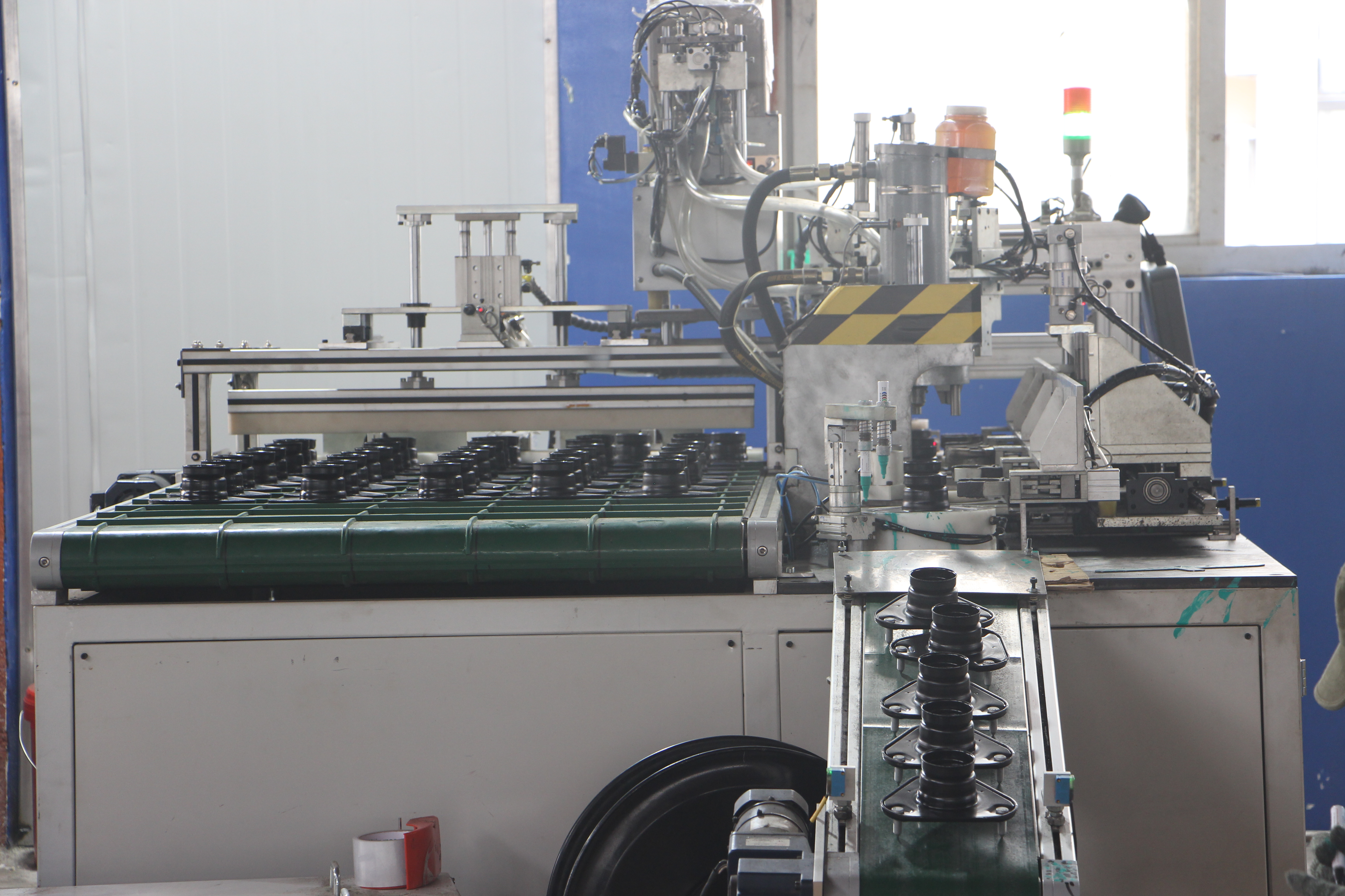
- Прототипиране – Изграждане и тестване на пробни части за прилягане и функционалност.
- Пробен штамп – Настройване на матрици и преси за постигане на възпроизведими, бездефектни форми.
- PPAP (Процес за одобрение на производствени части) – Потвърждаване, че процесът на изпънване отговаря на стандарти за качество и способност.
- Сериено производство – Започване на високотонажни серии с непрекъснато наблюдение.
- Непрекъснато подобрение – Оптимизиране на процеса, инструментите и контрола за подобряване на добива и намаляване на разходите.
Конструкцията, материала, матрицата и процесът трябва да бъдат оптимизирани заедно, за да се постигнат целите за разходи и производителност.
Крайно автомобилно метално штампиране целта е осигуряването на мащабируемо, икономически ефективно производство на автомобилни части, които отговарят на високите изисквания за дълготрайност, безопасност и външен вид. Като разберете тези основни принципи, ще сте готови да навлезете по-дълбоко в избора на процеси, правила за проектиране за производственост (DFM), стратегии за инструменти и други теми, докато изучавате останалата част от това ръководство.
Типове процеси и основни аспекти при избора
Прогресивен срещу трансфер: Избор на правилния път
Когато сте пред нов проект за автоштамповане, един от първите въпроси е: кой производствен процес на штампиране на метали ще осигури най-добро съчетание от скорост, разходи и качество? Отговорът зависи от геометрията на детайла, изискваните допуски и обема на производството. Нека анализираме най-често използваните методи за штамповане при автоштамповани части и да видим в коя област всеки един се проявява най-добре.
| Вид процес | Типични характеристики на детайла | Качество на ръба/равнинността | Време за изработка на инструментариум | Най-добър за |
|---|---|---|---|---|
| Прогресивна форма | Скоби, клипове, свързващи елементи, множество функции, умерена дълбочина | Добро, последователно; подходящо за повечето автомобилни нужди | Среден до дълъг (поради сложността) | Штамповане в големи серии, малки до средни по размер части, сложни, но повтарящи се елементи |
| Трансферен шанец | Големи панели, рамки, черупки, дълбоки изтегляния, конструкционни части | Добре, може да обработва по-сложни форми | Средно до дълго (сложни механизми за пренасяне) | Средно до високо количество, големи или дълбоко изтеглени автомобилни штамповани части |
| Фина преса | Зъбни колела, верижни зъбци, компоненти на колан за сигурност, остри елементи | Отлично; тесни допуски, гладки ръбове | Дълго (специализиран инструмент) | Висока точност, критични за безопасността компоненти, части с минимални заострения |
| Fourslide/multislide | Малки конектори, терминали, части с множество огъвания | Много добро за сложни огъвания | Кратко до средно | Нисък до среден обем, сложни форми, гъвкаво производство |
| Дълбоко теглене | Дълбоки купи, корпуси, черупки | Добра, при подходяща смазка и конструкция на матрицата | Среден | Конструкционни капаци, резервоари за гориво, дълбоко изтеглени автомобилни штамповани части |
Бележки към таблицата: Прецизното пробиване е най-подходящо за части, които изискват много гладки ръбове и минимални заравнения; прогресивните матрици са оптимални за високотомажно метално штамповане на прогресивно штамповани автомобилни части; трансферните матрици обработват по-големи или по-сложни форми; fourslide е най-добър за сложни компоненти с множество огъвания, но по-малко подходящ за дебели или големи предмети.
Приложения на дълбокото изтегляне и прецизното пробиване
Представете си, че трябва да произведете скоба за предавка и зъбно колело на колан за сигурност. Скобата, с множеството си огъвания и отвори, е идеален кандидат за стъпково щамповане — бързо, ефективно и икономически изгодно при производство на милиони бройки. Зъбното колело за колана обаче изисква изключително гладки ръбове за безопасност. Тук решението е прецизно изрязване (fine blanking), което осигурява извънредно високо качество на ръба и тесни допуски, макар и при по-висока цена на инструментите и по-дълго време за настройка.
Балансиране на допуски, скорост и разходи
Всеки штампиране в автомобилната индустрия има своята оптимална област. Стъпковите матрици предлагат ненадмината скорост и по-ниска цена на бройка при големи серии, но първоначалните разходи са високи. Матриците с прехвърляне осигуряват гъвкавост за сложни форми с дълбоко изтегляне, докато прецизното изрязване се използва за детайли, критични по точност, където качеството на ръба не може да бъде компрометирано. Fourslide и дълбокото изтегляне попълват важни ниши за специализирани геометрии и дълбоки форми.
- Ако се нуждаете от висока производителност и последователни характеристики: Прогресивна форма
- Ако детайлът е голям или изисква дълбоко оформяне: Трансферен шанец или дълбоко теглене
- Ако е необходимо ръбовете да са без заравни и прецизни: Фина преса
- Ако дизайна ви включва множество огъвания или сложни форми в компактно изпълнение: Fourslide/multislide
- За метални части с висок обем често най-икономични са прогресивните матрици.
- Автомобилни шамарени части с изящни, дълбоки елементи може да изискват трансферни матрици или дълбоко изтегляне.
- Метални шамарени части за зони на безопасност или видими области може да изискват финото изрязване, за да се минимизира довършването и да се осигури качеството.
Оптималният процес е този, който минимизира общата крайна цена, като отговаря на изискванията за формируемост, допуски и последващо съединяване.
Докато оценявате следващия си проект за производство чрез метално шамарене, внимателно претеглете тези компромиси. Правилният избор ще опрости работния процес, ще намали отпадъците и ще осигури устойчиво, възпроизводимо качество — подготвяйки програмата ви за успех, докато преминавате към избора на материали и покрития.
Материали и покрития, които повишават производителността при автомобилно метално шамарене
Избор между стомана и алуминий за шамарени части
Когато избирате материали за метално штамповане в автомобилната промишленост, първото голямо решение често се свежда до стомана или алуминий. Всеки от тях предлага уникални предимства и предизвикателства, които оказват влияние върху целия процес на автомобилно штамповане. Така че как да изберете?
Стоманени ламарини за штамповка продължава да бъде основният материал за скоби, панели на каросерията (body-in-white) и структурни усилвания. Нисковъглеродните стомани са лесни за формоване и заваряване, докато високопрочните нисколегирани стомани (HSLA) предлагат оптимално съчетание от якост, намалена маса и подобрена корозионна устойчивост. Напредналите високопрочни стомани (AHSS) повишават нивото на безопасност при сблъсък и намаляване на теглото, но изискват внимателно проектиране, за да се избегнат пукнатини и прекомерно огъване след штамповане.
От друга страна, частни части от алуминиево тиснене са предпочитаният избор за затварящи елементи, капаци, покриви и други области, където всеки грам има значение. Отличното съотношение между якост и тегло на алуминия и неговата естествена корозионна устойчивост са големи предимства за икономия на гориво и пробег при електрически превозни средства (EV). Въпреки това, процесът на алуминиево штамповане внася собствен набор от предизвикателства: по-голямо огъване назад, по-ниска формоустойчивост в близост до точката на стесняване и по-голяма склонност към залепване по време на формоване.
| Материално семейство | Типичен диапазон на толщината | Формируемост | Склонност към възвръщане | Свариваемост | Чувствителност към повърхностната отделка |
|---|---|---|---|---|---|
| Нисковъглеродна стомана | 0.6–2.0 mm | Отлична; лесни огъвания и изтегляния | Ниски | Много Добро | Умерена |
| HSLA стомана | 0.8–2.5 mm | Добра; по-висока якост, умерена формоустойчивост | Умерена | Добре | Умерена |
| AHSS | 0.7–2.0 mm | Умерена; изисква достатъчно големи радиуси, внимателно проектиране | Високо | Предизвикателно (предварително загряване или специални процеси могат да помогнат) | Високо (повърхностните дефекти са по-видими) |
| Алуминиеви сплавове | 0.7–2.0 mm | Добро в началото, ограничено при стесняване; склонно към залепване | Много високо | Умерено (може да изисква специални техники) | Високо (възможни драскотини, ефект на портокалова кора) |
| Мед/Латун | 0.3–1.0 мм | Отлично; меко, лесно за формоване | Ниски | Много Добро | Ниски |
Покрития и защита от корозия
Дори най-добрият метал няма да издържи без подходяща повърхностна защита. За струенизирани стомани се нанася цинков слой върху стоманата, осигуряващ жертвена корозионна устойчивост, особено важна за долната част на шасито и външните панели. Галванизираните покрития, при които цинкът се термично обработва, предлагат подобрена боядисваемост и последователност при точково заваряване — важно за сборки тип body-in-white (BIW).
Сплавите от алуминий често разчитат на естествения си оксиден слой, но за агресивни среди могат да се нанасят допълнителни покрития. Анодирането уплътнява оксида за подобрена защита, но може да бъде по-малко ефективно в ръбовете или ъглите. За още по-тежки условия плазменоелектролитното оксидиране (PEO) създава плътен, твърд и химически пасивен слой, подходящ за изискващи среди при горещо штамповане на метали (Keronite) .
Боите, праховите покрития и полимерните системи предлагат допълнителни възможности – всяка с компромиси относно цена, дебелина, издръжливост и крайна обработка. Правилното покритие трябва да се избере още в началото, с участието на екипите по проектиране и производство, за да се осигури съвместимост с последващите процеси за свързване и финиширане.
Възможности за формоване на материала и съображения за еластичност
Представете си оформянето на дълбока купа от AHSS или формоването на прецизен капак от алуминий. Риска от пукване, гънки или еластичен връщане е реален. По-високият модул на Юнг на стоманата означава, че тя запазва по-добре формата си след формоване, с по-малко еластично връщане в сравнение с алуминия. Алуминият, въпреки че първоначално се огъва по-лесно, има по-голямо еластично връщане – което изисква допълнително огъване или повторно формоване, за да се постигне целевата геометрия.
Материали за прецизно метално щамповане като мед и месинг са идеални за електрически екрани и корпуси на съединители благодарение на мекостта и проводимостта им, но не притежават необходимата якост за конструктивни части. При всички материали е от съществено значение внимателно да се управляват радиусите на огъване, смазването и разположението на протяжни ребра, за да се избегнат дефекти и да се минимизира преработката.
- Избирайте достатъчно големи радиуси на огъване за AHSS, за да се намали риска от пукнатини.
- Проверете стратегията за смазване при алуминий, за да се контролира залепването по време на процеса на щамповане на алуминий.
- Планирайте дизайни на фланци и краища за съвместимост с боядисване и покрития, особено при изисквания за високотемпературно метално щамповане.
- Още от началото балансирайте нуждите от формируемост, заваряемост и качеството на повърхността.
Изборът на материал трябва да се прави с оглед избрания процес за щамповане и стратегията за матрици, за да се избегне преработка на късен етап.
Като вземете предвид тези фактори, свързани с материала и покритието, още в началото ще осигурите здраво и икономически ефективно метално щамповане за автомобилна промишленост, като гарантирате, че вашите части са готови за следващата серия проверки по DFM и процесно инженерство.

Правила за DFM и метрики за процесно инженерство
DFM правила за надеждно оформяне
Когато проектирате метални штампувани части за автомобилна промишленост, малки решения в началото могат да означават разликата между гладко производство и скъп брак. Звучи сложно? Не е задължително. Като приложите проверени правила за проектиране с оглед технологичността (DFM – Design for Manufacturability), ще намалите риска, ще предпазите инструментите си и ще осигурите правилното функциониране на штамповките от първия път. Ето какво трябва да знаете:
- Минимална ширина на фланжа: Предвиждайте фланци с достатъчна ширина, за да се избегне разкъсване — обикновено поне 3–4 пъти дебелината на материала за повечето видове стомана и алуминий. По-тесни фланци могат да доведат до пукнатини по време на формоване (Shaoyi Metal) .
- Разстояние от дупка до ръб: Разполагайте отворите на разстояние най-малко 1,5 пъти дебелината на материала от края, за да се предотврати деформация или пукане по време на процеса на штамповане.
- Радиуси на огъване: За въглеродисти стомани използвайте вътрешни радиуси ≥ 1x дебелина на материала; за HSLA или AHSS използвайте до 2–3x дебелина. При алуминия често са необходими още по-големи радиуси, за да се минимизират пукнатините и еластичното възстановяване.
- Разположение на гофри и релефи: Позиционирайте перли и релефи на разстояние от критични възли и ъгли, за да контролирате потока на метала и да намалите локалното изтъняване.
- Релефни елементи за сложни изтегляния: Добавете изтеглителни пръстени или релефи, за да управлявате движението на материала и да избегнете гънки при дълбоки или многостепенни форми.
Като следвате тези насоки, ще забележите по-малко корекции на инструменти и по-сравним изход от вашата оборудване за штамповане на ламарини. Резултатът? По-ниски проценти скрап и по-бързо време до SOP.
Допуски при изтегляне и опростяване на измерванията
Определянето на правилните допуски зависи от функционалността – а не от съвършенство навсякъде. Ето бърз списък за здрави и икономически ефективни чертежи:
| Характеристики | Препоръчителна практика |
|---|---|
| Равност | Прилагайте стегнати допуски за равнинност само там, където съединяването или уплътняването е критично. |
| Вярна позиция | Използвайте за отвори или фланци, които определят положението на сглобките; избягвайте при некритични елементи. |
| Посока на заострените ръбове | Уточнете посоката на заострените ръбове при повърхности, които се съединяват с други части. |
| Система от референтни равнини | Закрепвайте референтните равнини към оформени повърхности, а не към плоски заготовки, за да отразяват реалната сглобка. |
| Контрол на елементи | Използвайте геометрични и размерни допуски избирателно; насочете вниманието към елементи, които влияят на сглобката или функцията. |
Поддържането на реалистични допуски помага за контролиране на разходите и осигурява устойчив процес за производство чрез метално штамповане в големи мащаби (Shaoyi Metal) .
Тонаж на пресата, време за цикъл и фактори, определящи добива
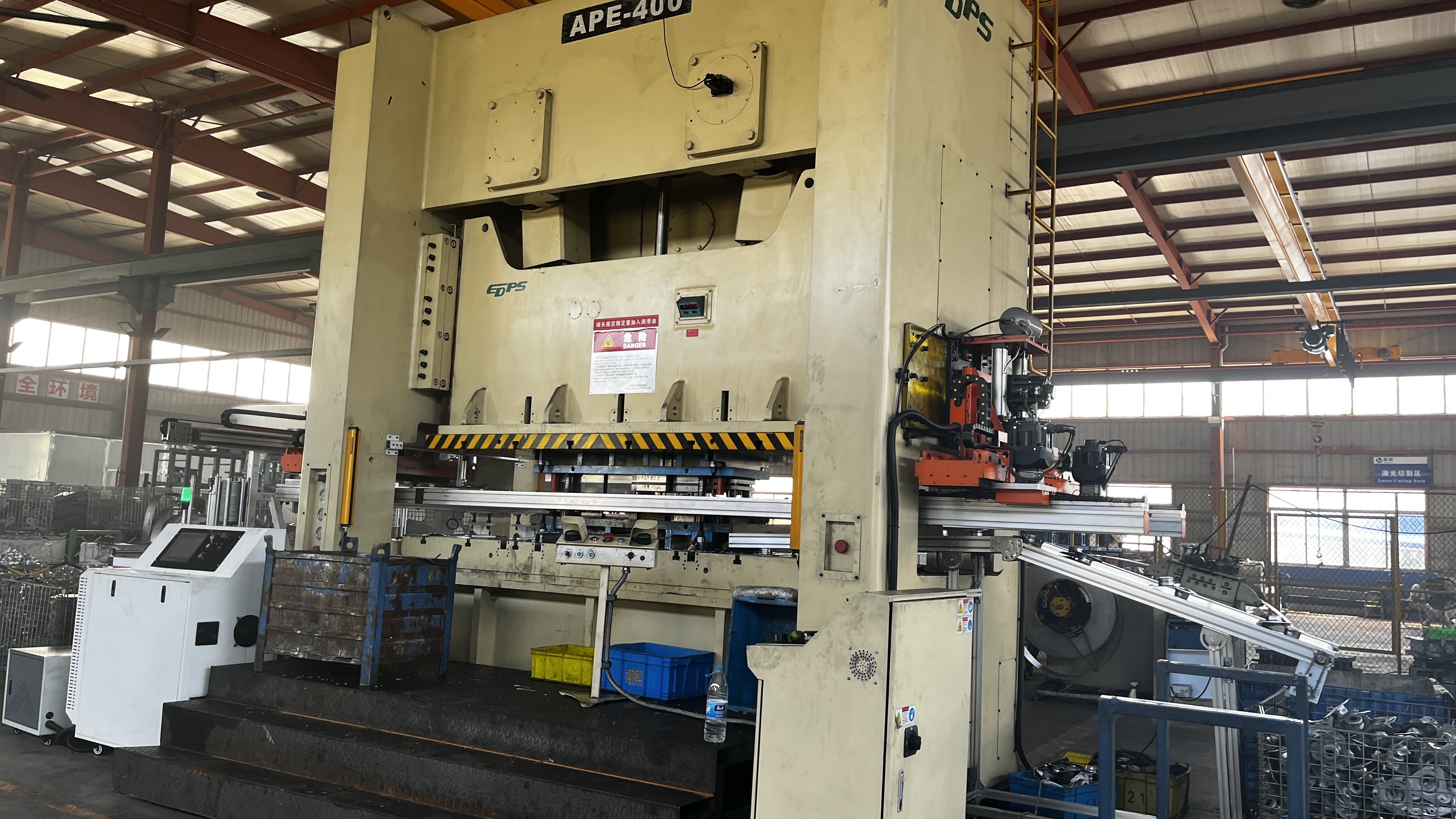
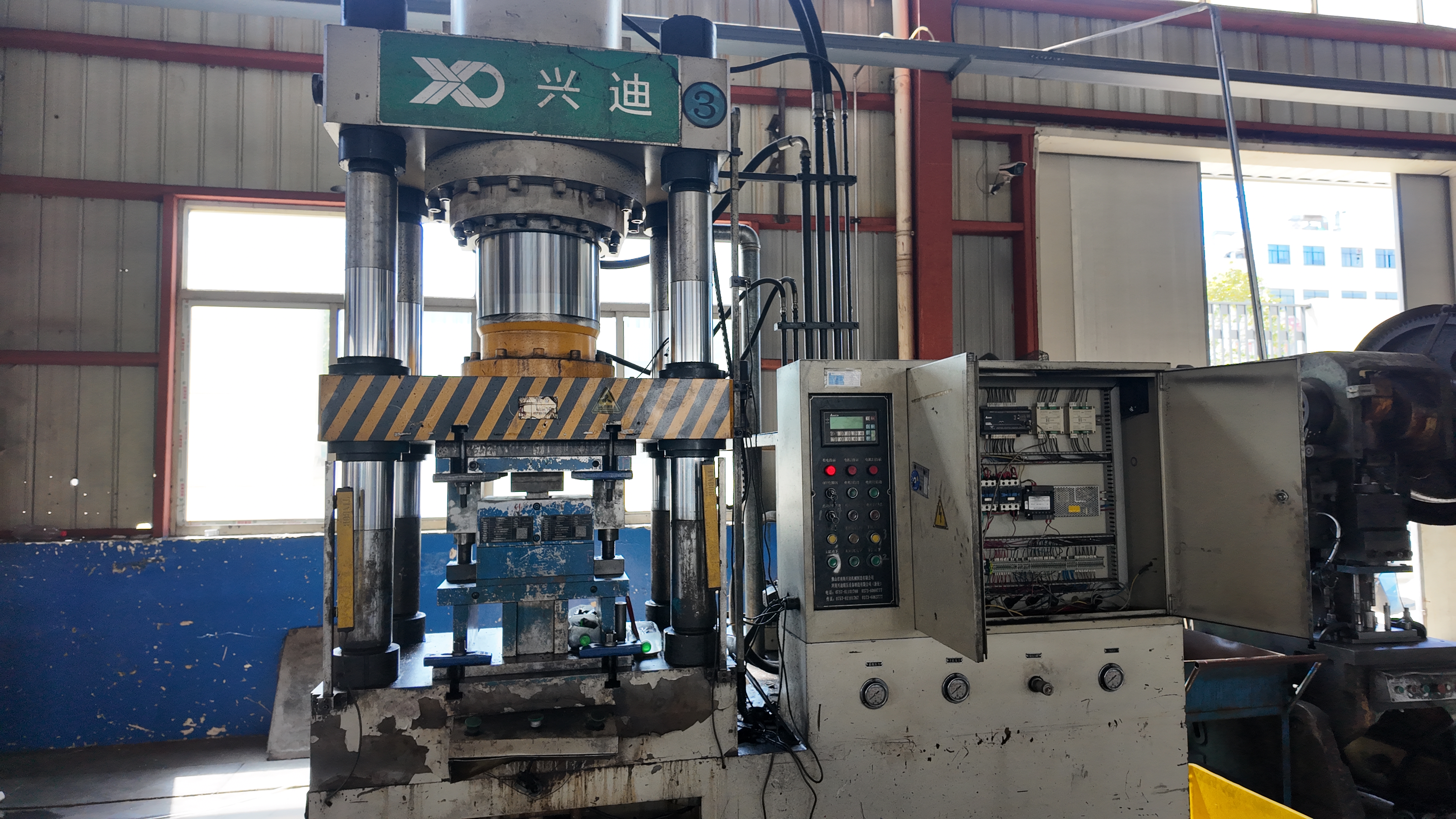
Задавали ли сте си въпроса защо някои штамповъчни линии работят безпроблемно, докато други имат проблеми с простоюване? Причината често се крие в избора на подходящата промишлена штамповъчна преса за детайла и процеса. Ето какво трябва да имате предвид:
- Тонаж: Изчислете необходимата сила на пресата въз основа на периметъра на детайла, дебелината и якостта на материала при срязване. Винаги добавяйте резерв от 10–20%, за да компенсирате динамичните натоварвания и износването на инструмента.
- Размер на масата и ход Уверете се, че пресата може да побере най-голямата ви матрица и пълния ход, необходим за формоване.
- Скорост: Съгласувайте скоростта на пресата с материала и сложността на детайла; по-бързо не винаги е по-добре, ако увеличава риска от дефекти.
- Фактори, влияещи на цикъла: Дължината на подаване, броят на станциите и нивото на автоматизация влияят върху производителността. Прогресивните матрици осигуряват максимална скорост при прецизно штамповане на метал, докато трансферните матрици могат да забавят цикъла при сложни форми.
Изборът на подходящо оборудване за штамповане на листов метал и настройката на тези параметри могат да определят успеха или провала на програмата ви по отношение на разходи и добив.
Управление на остатъчната деформация и вариациите
Остатъчната деформация — склонността на метала да се върне към първоначалната си форма след формоване — е един от основните проблеми, особено при AHSS и алуминий. Как да запазите штампованите компоненти в спецификация?
- Стратегии при пробното изпитване: Използвайте оптимизация на добавките и настройка на усукващите ролки, за да контролирате потока на материала и да минимизирате остатъчната деформация по време на разработване на матриците.
- Компенсационни стратегии: Прилагайте ъгли на огъване, допълнителни кулиси или шайби за коригиране на ефекта от еластичното възстановяване при прецизни операции по клапане на метал.
- Първо симулация: Използвайте цифрово моделиране на формоване, за да предвидите гънки, пукнатини и изтъняване, преди да бъде нарязана стоманата – това спестява време и преработки.
Ако референтните материали предоставят конкретни граници на допуск или цели за Cpk, включете ги; в противен случай дефинирайте цели за способност, съобразени с практиките за качеството в автомобилната промишленост.
Като внедрите тези най-добри практики от DFM и процесното инженерство, ще осигурите повтаряем успех на проекта си за клапане на метал в автомобилната промишленост – преминавайки от дизайн към производство с по-малко изненади. Следващия път ще разгледаме как надеждните системи за качество и стратегиите за инспекция гарантират тези постижения за дълъг период.
Стратегия за инструменти и управление на живота на матриците
Материали за матрици и покрития за по-дълъг живот
Някога се чудили защо някои штамповъчни матрици издържат милиони цикли, докато други се износват след само няколкостотин хиляди? Тайната е в правилната комбинация от материал на матрицата, покрития и разумно поддържане. В индустриален металообработващ штамповъчна машина среди, изборът на подходящ инструментална стомана е от решаващо значение – особено тъй като при проектирането на автомобили все по-често се изискват високоякостни стомани (AHSS) и алуминиеви сплави.
За повечето автомобилни приложения материалите за матрици попадат в три основни категории: леени чугуни, леени стомани и инструментални стомани. Традиционните инструментални стомани като D2, A2 и S7 служат на индустрията от десетилетия, но тъй като класовете AHSS достигат нива на твърдост до четири или пет пъти по-високи от тези на меката стомана, често традиционните сплави не са достатъчни. За изискващи приложения, инструменталните стомани от прахова металургия (PM) предлагат голям напредък както по отношение на устойчивостта към износване, така и по отношение на якост, значително удължавайки живота на матриците дори при високи натоварвания (AHSS Insights) .
Повърхностните обработки и покрития са друга линия на отбрана. Нитрирането, пламенното закаляване и напредналите PVD покрития като титанов нитрид (TiN), титан-алуминиев нитрид (TiAlN) и хромов нитрид (CrN) създават твърди, малко триещи повърхности, които устояват на залепване и абразивно износване. Например, матрица с PVD покритие от хромов нитрид може да произведе над един милион части, спрямо само 50 000 за инструмент с хромово покритие. Правилното покритие също зависи от материала на листа — йонното нитриране често дава най-добри резултати при цинковани стомани, докато TiAlN се проявява отлично при високотемпературно и високоналягано формоване (The Fabricator) .
Модели на разрушаване: износване, залепване и пукнатини
Представете си, че стартирате серийно производство и изведнъж преждевременно спирате. Какво се обърка? Повечето повреди на матрици при индустриална метална штамповка и механична обработка се дължат на няколко основни причини:
- Абразивно износване: Твърди частици в листа или матрицата изтриват материал, особено при високи контактни налягания.
- Адхезивно износване (залепване): Листовият метал се "заварява" към матрицата, след което откъсва парчета, повреждайки и двете повърхности.
- Пластична деформация: Прекомерната усилие при избиване надвишава натисковата якост на матрицата, причинявайки постоянна деформация.
- Разпукване и пукнатини: Повтарящи се високи натоварвания или концентратори на напрежение (като остри ъгли) предизвикват пукнатини, които водят до катастрофален отказ.
Въпреки че покритията и напредналите стомани помагат, здравословният дизайн на матрицата е основата. Матрици с подходяща подкрепа, центриране и интеграция на сензори устояват на вибрации и преждевременно разрушаване. Не забравяйте: смазването е еднакво важно — неравномерното или недостатъчно смазване може да ускори износването и да доведе до ранен отказ дори на най-добрите матрици.
Превантивно поддържане, което се изплаща
Възприемете превантивното поддържане (ПП) като ваша "застраховка" за последователно качество на детайлите и надежден работен режим. Активното ПП не само удължава живота на матриците, но също така ви помага да избегнете скъпи аварийни ремонти и загуба на производство. Ето практически списък за поддържане на инструментите ви във върхова форма — ключов за всеки решения за индустриални метални щанци програма:
- Планирани проверки: Редовно проверявайте за видими следи от износване, пукнатини или повреди — фокусирайте се върху зоните с висок износ и участъците за вмъкване.
- Подмяна на вметките: Заменяйте износените или повредени вметки преди те да повлияят на качеството на детайлите или да причинят повреди по-надолу по веригата.
- Подравняване на матричния комплект: Проверете и коригирайте подравняването на матрицата, за да се предотврати неравномерно натоварване и преждевременно износване.
- Състояние на избутвачите/пружините: Проверявайте пружините и избутвачите за умора или счупвания; подменяйте ги при нужда, за да се осигури постоянна екстракция на детайлите и правилно функциониране на матрицата.
- Смазване и поддръжка: Осигурете се, че всички движещи се части и контактни повърхности са правилно смазани, като използвате правилния тип и количество за вашето приложение.
- Проверка на сензорите в пресата: Тествайте и калибрирайте регулярно сензорите, за да засечете неправилно подаване или заклещване на детайли, преди да доведат до повреда на инструмента.
| Станция | Компонент | Режим на отказ | Корективно действие | Следващо планирано |
|---|---|---|---|---|
| Изсичане | Прожекция | Абразивно износване | Прешлифоване, проверка на покритието | След 100 000 удара или според графика |
| ОБРАБОТКА | Вложка на матрицата | Заледяване | Полиране, повторно покритие, настройка на смазването | На всеки цикъл на поддръжка |
| Рязане | Резен край | Отчупване | Замяна, преглед на класа на материала | Наблюдение на броя удари до повреда |
Таблица: Примерно проследяване на живота на инструмента — персонализирайте колоните според нуждите на вашата работилница и отчитайте критични точки за целенасочени подобрения.
Регистрирането на броя удари до повреда и анализът на износването ви помагат да оптимизирате наличността на резервни части и да планирате преоформяния или подмяната преди повреда да прекъсне производството. Предиктивни технологии – като анализ на вибрациите или топлинно образуване – могат допълнително да усъвършенстват стратегията ви за профилактично поддържане, като засичат малки неизправности, преди те да се влошат.
Ранното откриване и дисциплинираното профилактично поддържане правят матриците предвидими, което стабилизира възможностите и намалява аварийните реакции по време на увеличаване на производството.
Чрез инвестиране в подходящите материали за матрици, напреднали покрития и надеждна рутина за профилактично поддържане, ще повишите не само продължителността на живота на матриците, но и ще гарантирате производството на последователни висококачествени детайли в автомобилната металоштамповка – като създадете основа за силни системи за качество и документация в следващия етап.
Инспекция и документация на системите за качество
Какво включва ефективен план за контрол?
Когато осигурявате или проектирате метални штампосани автопчасти , не можете да оставите качеството на случайността. Представете си един скоб, който не отговаря на спецификациите, да попадне в сглобката на спирачната система — последствията могат да бъдат призоваване обратно и щета за репутацията. Затова автомобилната индустрия поставя високи изисквания чрез структурирани системи за качество, базирани на световно признати рамки и строга документация.
В сърцето на тази система е Планът за контрол — динамичен документ, който описва всеки критичен етап от процеса, точка за инспекция и план за реакция за вашия штампованите метални съединения . Но как точно изглежда пълен комплект от инструменти за качество в производството на метални шематури за автомобилна индустрия?
| Артефакт | Цел | Собственик | Момент на обновяване |
|---|---|---|---|
| DFM/Осъществимост | Потвърждаване, че детайлът може да се произвежда надеждно; ранна идентификация на рискове | Доставчик/Инженер по проектиране | Преди стартиране на инструменти; когато има промени в дизайна |
| PFMEA | Системно оценяване и намаляване на рисковете от неуспехи в процеса | Инженер по процеса на доставчика | Начално настройване на процеса; след големи промени |
| Контролен план | Определяне на контроли, проверки и планове за реакция за всяка стъпка от процеса | Качество на доставчика/Производство | starтиране; след промени в процеса или продукта |
| MSA/Gage R&R | Потвърждаване, че измервателните системи са точни и възпроизводими | Качество на доставчик | Ново оборудване; периодично според график |
| Проучване на способностите | Демонстриране, че процесът може постоянно да отговаря на допуснатите отклонения | Качество/процес на доставчика | Преди PPAP; след значителни промени в процеса |
| Първоначален контрол на артикула (FAI) | Проверка дали първите серийни изделия отговарят на всички изисквания | Качество на доставчик | Начално производство; промени в конструкцията/процеса |
| Подаване на PPAP | Изчерпващи доказателства за готовността на процеса и продукта | От доставчик към клиент | Преди сериено производство; след значителни промени |
Таблица: Ключови артефакти за качество в автомобилното щанцоване, съобразени с практиките на IATF 16949. Всеки от тях гарантира, че прецизните метални щанцовки отговарят на най-високите стандарти в индустрията по отношение на безопасност и надеждност.
PPAP и FAI: Какво да очаквате
Задавали ли сте си въпроса защо автомобилните програми изискват толкова обширна документация преди производството? Отговорът се крие в Процеса за одобрение на производствени части (PPAP) и Първата артикулна проверка (FAI). PPAP е вашето официално потвърждение към клиента – демонстриране, че вашият процес последователно произвежда части, които отговарят на всички изисквания, от размерна точност до повърхност и функционалност. FAI е първото реално доказателство: пълна проверка на началните части спрямо всички критерии на чертежите и спецификациите, често използвайки напреднали инструменти като КИМ и оптични визуални системи.
Тези стъпки не са просто хартиена работа — те са основата за проследяване и намаляване на рисковете. Пълният пакет PPAP обикновено включва диаграми на процесните потоци, PFMEA, планове за контрол, сертификати за материали, капацитетни изследвания и доклади от първичен възлов инспекционен контрол (FAI). За прецизни штампани части , този уровень на проверка гарантира, че всеки елемент — до последния огънат участък или отвор — ще бъде точен при всяко производство.
Проследяване и маркиране на части в автомобилната промишленост
Представете си ситуация, при която дефект бъде открит месеци след доставката. Как да установите коя партида е засегната? Точно тук влизат в действие маркирането на автомобилни части и системите за проследяване. Всяка партида — или дори всеки отделен компонент — може да носи уникален идентификатор, като лазерно гравиран код или ударен сериен номер, което позволява да се проследи пътят му от суровината до готовата сглобка. Това проследяване е важно не само за качеството при одитите, но и за бързи, целенасочени отзиви при нужда.
Практиките за маркиране в автомобилната промишленост се формират от изискванията на клиентите и отрасловите стандарти. Кодовете могат да включват дата, смяна, номер на матрицата или дори идентификация на оператора. За сложни штампованите метални съединения , поддържането на този уровень на проследимост между множество подкомпоненти е отличителна черта на качествени системи световно ниво.
- Стратегии за вземане на проби: Определяне на броя на частите, които ще бъдат проверени на партида, въз основа на риска и стабилността на процеса.
- Класификация на характеристики: Идентифициране на това кои параметри са критични, основни или второстепенни – така че усилията при инспекцията да бъдат насочени там, където имат най-голямо значение.
- Методи за измерване: Използване на калибрирани щипци, КИМ или оптични системи, съобразени с необходимата точност за всеки параметър.
- Честота на калибриране: График за редовно калибриране на инспекционното оборудване, за да се осигури постоянна точност.
- Планове за реагиране: Определете ясни стъпки за справяне с несъответствия — локализация, анализ на основната причина, коригиращи действия и актуализации на документацията.
Ясна документация и проследими, възпроизводими инспекции предотвратяват неясноти и осигуряват гладко производство.
Чрез вграждането на тези елементи на системата за качество във вашия автомобилно метално штампиране работен процес, ще отговаряте не само на изискванията на клиентите и регулаторните органи, но също така ще изградите увереност, че вашите прецизни метални штамповки ще работят безупречно при всяка сглобка. Следващо, ние ще осигурим на екипите по набавяне инструментите за ЗНЦ и рамките за оценка на доставчиците, необходими за превръщане на тези стандарти в конкретни решения по набавянето.
Инструментариум за ЗНЦ и рамка за оценка на доставчици за автомобилни метални штамповки
Основи на ЗНЦ: Обхват, допуски и обеми
Когато сте готови да набавяте части за автомобилна метална штамповка, качеството на вашата Заявка за оферта (RFQ) може да определи успеха или провала на проекта ви. Звучи сложно? Не е задължително. Представете си, че сте мениджър по набавяне, който трябва да съобразява строги срокове, целеви разходи и нужда от надеждни доставчици. Ясната и изчерпателна заявка ще ви помогне да привлечете подходящите производители на метални штампувани части и да елиминирате тези, които не могат да изпълнят.
- 2D/3D CAD файлове – Пълни чертежи с размери, допуски, материали и спецификации за повърхностна обработка
- Годишен обем по производствена година – Помага на доставчиците да определят мащаба на инструментите и да планират капацитета
- Целево ниво на PPAP – Задава очакванията за качествената документация
- Изисквания към материала и покритието – Стомана, алуминий или специални сплави, както и всички видове повърхностни обработки
- Специални характеристики – Критични елементи, изисквания за безопасност или регулаторни изисквания
- Опаковане и етикетиране – Стандарти за EDI/етикетиране, спецификации за опаковане
- Срок на служба – Очакван живот на инструменти и части
Фрагмент от шаблон за поръчка (RFQ):
- Притежание на матрици (доставчик или клиент)
- Количество пробни образци и процедура за одобрение
- Целеви показатели за способност (стойности Cp/Cpk, ако са задължителни)
- Протоколи за контрол на промените и управление на ревизиите
Критерии за оценка на доставчици: възможности, рискове и разходи
Изборът между компании за автомобилно штамповане не зависи само от цената – важното е да се намери партньор, който постоянно може да осигурява качество, обем и техническа поддръжка. Препоръчително е да сравнявате доставчиците, като използвате както количествени, така и качествени данни – от сертификати до дълбочина на DFM и практики за управление на риска. Помислете за тези критерии, базирани на най-добри практики:
| Доставчик | Сертификати | Поддръжка DFM | Собствени инструменти | Обхват на пресите | Експертност по материали | Време за изработка на прототип | Времето за производство | Логистика/Местоположение | Обща крайна цена |
|---|---|---|---|---|---|---|---|---|---|
| Shaoyi Metal Technology | IATF 16949 | Комплексен DFM, прототипиране до масово производство | Да | До 800 т | Високоякостни стомани (AHSS), алуминий, специални сплави | Рапид | Кратко до средно | Глобален | Конкурентен |
| Acro Metal Stamping | ISO 9001 | Инженерна помощ, оптимизация на дизайн | Да | Разнообразен | Стомана, алуминий, мед | Среден | Среден | САЩ | Пазарна цена |
| Manor Tool & Manufacturing | ISO 9001 | Поддръжка на процеса и дизайна | Да | Широк | Стомана, алуминий, никел | Среден | Среден | САЩ | Пазарна цена |
| Klesk Metal Stamping | ISO 9001 | Напреднал EDM, висока прецизност | Да | Разнообразен | Комплексни сплави | Среден | Среден | САЩ | Пазарна цена |
| Kenmode, Inc. | ISO 13485, ISO 9001, IATF16949 | Персонализирани, високопрецизни | Да | Разнообразен | Стомана, алуминий, мед | Среден | Среден | САЩ | Пазарна цена |
Таблица: Пример за сравнение на доставчици за компании, произвеждащи метални штамповки за автомобилна промишленост, включващи група от производители на прецизни метални штамповки и производители на штампосани части. Винаги потвърждавайте детайлите с всеки доставчик на метални штампосани части, за да съответстват на вашите специфични изисквания.
- Разполага ли доставчикът с признато управление на качеството (като IATF 16949 или ISO 9001)?
- Могат ли да предоставят обратна връзка по проектирането за производимост (DFM) в ранен етап, или котират само според чертежите?
- Притежават ли собствени форми, или те са аутсорснати?
- Какъв е техният послужен списък по отношение на водещо време, своевремено доставяне и управление на рискове?
- Имат ли опит с изискваните от вас материали (напр. AHSS, алуминий)?
- Колко прозрачни са те относно разходите, капацитета и плановете за извънредни ситуации?
От прототип до серийно производство: Изграждане на надежден план
След като сте ограничили списъка с доставчици на метални штампосани части, следващата стъпка е да се договорите за пътна карта от прототип до производство. Представете си, че стартирате нова програма за производство на автомобили — ще може ли вашият доставчик да нараства заедно с вас? Търсете партньори, които предлагат:
- Поддръжка за бързо прототипиране и ясни обратни връзки относно производимостта
- Вътрешен дизайн и поддръжка на инструменти за бърза итерация
- Дефинирани планове за увеличаване на производството с проверки на капацитета и стъпки за намаляване на рисковете
- Прозрачна комуникация относно управлението на промените и качеството
Като следвате тази рамка, ще минимизирате изненадите, ще намалите значително риска от набавяне и ще осигурите гладко стартиране на програмата за метално штамповане в автомобилната промишленост. Следващата стъпка е задълбочено запознаване с отстраняването на дефекти при штамповане и коригиращите действия — така веригата ви за доставки ще остане здрава от офертирането до качественото пускане.
Отстраняване на дефекти при штамповане и техните решения
Диагностициране на ръбове, набраздявания и напуквания
Забелязвали ли сте неравни ръбове, вълнистите повърхности или внезапни разкъсвания в щампованите метални части? Това са чести проблеми при производството чрез метално щамповане, но добрата новина е, че повечето дефекти имат ясни причини и практически решения. Нека разгледаме най-често срещаните проблеми, които може да срещнете при индустриалното метално щамповане, и как да ги отстраните, преди да наруши производствената ви линия.
-
Заешки опашки → Вероятна причина: Тъпи или износени режещи ръбове, неправилна междина на матрицата.
Решение: Ново заточване или подмяна на пуансони/матрици, настройка на междината на матрицата според дебелината на материала и осигуряване на подходящо смазване. Редовното поддържане на инструментите за щамповане на листов метал е задължително, за да се предотвратява образуването на заравняния. -
Завиване → Вероятна причина: Недостатъчна сила на държача на заготовката, лош дизайн на усукванията или прекомерен поток на метала.
Решение: Увеличете силата на държача на заготовката, променете дизайна или позицията на усукванията и проверете за равномерен поток на материала. Осигуряването на правилните настройки на вашата производствена щамповъчна техника може да направи значителна разлика. -
Напуквания/пукнатини → Вероятна причина: Твърде голяма дълбочина на изтегляне, остри радиуси, крехкост на материала или недостатъчна подкрепа от матрицата.
Решение: Увеличете радиусите, добавете или оптимизирайте изтеглителни пръстени, изберете по-еластични материали или коригирайте подкрепата на матрицата. Симулацията на процеса преди производството може да помогне за ранното откриване на тези рискове.
Контрол на отскока и отклонение в размерите
Случвало ли ви се е да формирате детайл, само за да установите, че не запазва предвидената форма? Отскокът е класическо предизвикателство, особено при високоякостни стомани и алуминий. Ако забелязвате, че след формоване детайлите не съответстват на чертежа, ето как можете да възстановите контрола:
-
Връщане след извиване → Вероятна причина: Материали с висока граница на остатъчна деформация (като AHSS или алуминий), недостатъчно преогъване или избор на инструментална стомана.
Решение: Въведете компенсация чрез преогъване в дизайна на матрицата, използвайте повторно натискане за фини настройки на крайната форма и прегледайте комбинациите от инструментална стомана/покрития. Коригирането на смазката и параметрите на процеса също може да помогне детайлът от штампован метал да остане в допусковите граници. -
Размерно изкривяване → Вероятна причина: Изнаждане на инструмента, непостоянна дебелина на материала или нецентриране на пресата.
Решение: Редовно калибрирайте пресата и матриците, следете наличните материали и приложете график за превантивно поддържане, за да отстранявате проблеми преди те да повлияят върху производството чрез метално штамповане.
Предпазване от повърхностни дефекти и залепване
Качеството на повърхността е от съществено значение, особено за видими или функционални автомобилни компоненти. Представете си, че откривате драскотини или неравни участъци след цял цикъл на производство — досадно, нали? Ето как да решите най-често срещаните повърхностни проблеми:
-
Вдлъбнатини/Напрежение по повърхността → Вероятна причина: Чужди частици (прах, масло, оксиди) в матриците или върху листовия метал.
Решение: Почиствайте внимателно матриците и листовия метал, използвайте въздушни продължаващи устройства или станции за бърсане и поддържайте чиста работна среда. -
Залепване (особено при алуминий) → Вероятна причина: Недостатъчно смазване, грапави повърхности на матриците или висока скорост на формоване.
Решение: Полирайте повърхностите на матриците, преминете към по-ефективно смазочно средство и обмислете коригиране на скоростта на пресата. При постоянни проблеми прегледайте покритията или повърхностните обработки на матриците. -
Апелинова кора/Грапавост на повърхността → Вероятна причина: Структура на зърното на материала, неправилна скорост на формоване или лошо качество на повърхността на матриците.
Решение: Използвайте материали с по-фини зърна, оптимизирайте скоростта на формоване и подобрете полиранията на матриците за по-гладка повърхност.
Когато има налични справочни данни за отслабване на дебелината или диаграми за граница на формоване (FLD), използвайте ги, за да зададете ясни граници за приемане. В противен случай разчитайте на симулации на формоването и контролирани проби, за да усъвършенствате процеса и параметрите си за устойчиви резултати.
Накрая, не пренебрегвайте стойността на структурирано решаване на проблеми. Приложете стандартизирани процеси за ограничаване и коригиращи действия по метода 8D, за да гарантирате, че всеки урок ще бъде документиран и включен обратно в Плана за контрол. Този подход не само намалява повторящите се дефекти, но и укрепва цялата операция по штамповане в производството.
С тези стратегии за отстраняване на неизправности ще бъдете подготвени да сведете до минимум времето за престой, да намалите брака и да поддържате безпроблемната работа на вашите индустриални линии за щамповане на метал. След това ще видите как изборът на щамповане пряко влияе върху структурните характеристики и критичния за безопасността дизайн в автомобилните приложения.
Структурна производителност и проектиране с критично значение за безопасността при метално штамповане в автомобилна промишленост
Проектиране на штампани конструкции за огъваемост
Когато си представите скелета на автомобил, какво го предпазва от огъване, тресене или смачкване под натоварване? Отговорът се крие в стратегическото инженерство на метални пресовани компоненти . Всяка ребро, гофриране и фланец в штампан елемент са внимателно разположени, за да насочват натоварванията, увеличават огъваемостта и отвеждат енергията от удара далеч от пътниците. Но как тези избори се превръщат в реална безопасност и дълготрайност?
Представете си подова плоча с внимателно избивани ребра. Тези елементи увеличават инерционния момент, като правят панела значително по-стабилен при огъване и вибрации. По същия начин разполагането на гофриране на разстояние от линиите на заварката предотвратява концентрация на напрежение, докато постоянните ширини на фланцовете осигуряват надеждни точкови заварки. Дори най-малките детайли – като радиуса на ъгъл или дебелината при прегъване – могат да направят разликата между част, която поема удара благоприятно, и такава, която се поврежда преждевременно.
- Стратегически избивки за повишаване на стабилността и съпротива срещу изкривяване
- Гофриране, разположено на разстояние от линиите на заварката за равномерно разпределяне на напрежението
- Постоянни ширини на фланцове за здрави точкови заварки
- Цялостност на ръба — гладки, без заострени ръбове, за избягване на образуване на пукнатини
- Оптимизирана дебелина на стената за предотвратяване на отслабване и локално умора
Стратегии за съединяване и цялостност на фланговете
Съединяването е моментът, в който гумата се допира до пътя — буквално. Лошо проектирани флангове или непостоянни точкови заварки могат да поставят под въпрос цялостта на оттиснати метални части при динамични натоварвания. Ще забележите, че най-добрите автомобилни метални штампованни части имат широки, равномерни флангове, които не само улесняват заварката, но и намаляват риска от разпространение на пукнатини от ръба. Качеството на гънката е еднакво важно за затварящи елементи като врати и капаци, където плътна, равномерна гънка осигурява както здравина, така и чиста повърхност за уплътняване и довършване.
Не става дума само за формата — важни са и изборът на материала, и контролът на процеса. Отслабването по време на формоване може да ослаби критични области, затова се използват инструменти за симулация, за да се прогнозира и компенсира разпределението на деформацията. Този превантивен подход помага да се запази необходимия живот при умора и поведението при сблъсък на всеки стоманен штиц .
Защита от корозия и издръжливост
Някога се чудили защо някои автомобилни части от листово метал които издържат десетилетия, докато други започват да ръждясват само след няколко сезона? Тайната е както в умното проектиране, така и в надеждната защита срещу корозия. Покрития като галванизация или специализирани бояди се избират според тяхната устойчивост към сурови среди. Но дори и най-доброто покритие не може да спаси лошо проектирана част. Остри ъгли, открити ръбове или неравномерни дебелини могат да се превърнат в точки на корозия, които подкопават структурната устойчивост. Затова обработката на ръбовете и продумното разположение на елементите са от решаващо значение още от самото начало.
| Структурна цел | Щампован елемент | Метод за валидиране |
|---|---|---|
| NVH (Шум, вибрации, дискомфорт) | Ребра, гофрирания, оптимизирана дебелина на стените | Тест за огъваща якост, модален анализ |
| Устойчивост при навлизане | Усилване, зони с висока якост | Симулация на катастрофа, тест за удар |
| Контрол на огъване | Релефни тиснения, шарки от гофриране, избор на материал | Симулация на формоване, физически тестове за огъване |
| Срок на живот при корозия | Обработка на ръбове, покрития | Тест със солен разпръск, тестове при външно въздействие |
Таблица: Съпоставяне на структурни цели с характеристики на процеса на штамповане и методи за валидиране при метални штамповани части за автомобили.
Валидацията не е просто отметка в квадратчето — тя представлява непрекъснат цикъл. Штампаните части първо се симулират (за формоване и устойчивост при сблъсък), след което се подлагат на физически изпитвания според изискванията на клиента или индустриални стандарти. Това гарантира, че всяка нова версия на конструкцията осигурява правилното съотношение между якост, тегло и дълготрайност, без изненади по пътя.
Структурната производителност зависи толкова от стабилно формоване и контрол на отклоненията, колкото и от номиналната конструкция.
Като съгласувате инженерните, материали и процесни избори, ще създавате штампани метални части, които не само отговарят, но и надминават изискванията на съвременните превозни средства. Готови ли сте да превърнете устойчивия дизайн в производствена реалност? Следващата стъпка е разработването на план за действие и установяването на връзки с проверени ресурси за успеха на вашия проект.
План за действие и проверени ресурси
Вашите следващи стъпки от DFM до PPAP
Готови ли сте да превърнете своята визия за автомобилни штампани метални части в качествени, готови за производство компоненти? Представете си увереността да преминете от дизайн до SOP с по-малко изненади, минимални отпадъци и силна подкрепа от доставчиците. Независимо дали стартирате персонализирани автомобилни штампани метални части за нова платформа на превозно средство или оптимизирате съществуващ проект, ясен и приложим план е най-добрият ви съюзник.
- Финализирайте своя пакет за заявка (RFQ): Уверете се, че всички чертежи, спецификации и годишни обеми са ясни. Включете материал, покритие и специални изисквания, за да могат доставчиците да предоставят точни оферти.
- Проведете DFM със списъка с предварително одобрени доставчици: Сътрудничество при прегледи за осъществимост. Този етап може да разкрие бързи постижения — като например коригиране на радиусите на огъване или местоположението на отвори — за намаляване на разходите и повишаване на добива.
- Съгласуване на избора на процес с подкрепа чрез симулация: Използвайте симулации на формоване и пробни прототипи, за да изберете подходящия метод за щамповане според геометрията и обема на детайла. Това помага да се избегне преустройство в късните етапи и гарантира, че вашите персонализирани щампосани части ще бъдат надеждни от самото начало.
- Потвърждаване на обхвата на инструментите и плана за поддръжка: Определете дизайна на матриците, материали и покрития от самото начало. Задайте очаквания за превантивна поддръжка и стратегии за резервни части, за да максимизирате времето на работа.
- Определете изискванията за проверка и документация PPAP: Съгласувайте документацията за качество, плановете за вземане на проби и протоколите за проследяване — задълго преди стартиране на производството.
- Планирайте етапи за постепенно увеличаване на производството: Включете ключови етапи за одобрение на прототип, пилотни серии и SOP. Това държи всички синхронизирани и готови да реагират, ако възникнат проблеми.
Изберете процеса, който минимизира общата цена за възможностите, а не само цената на инструментите.
Създаване на пътна карта от прототип до производство
Звучи като много неща, които трябва да се управляват едновременно? Не сте сами. Много екипи намират полза от партньорство с доставчик, който предлага поддръжка от начален DFM до масово производство. Например, Shaoyi Metal Technology доставя индивидуално штамповане на метални компоненти в автомобилната индустрия решения, в които имат доверие глобални автомобилни производители. Техният сертифициран по IATF 16949 обект осигурява бързо прототипиране, собствено инструментално оснащване и мащабируемо производство в широк диапазон от материали, включително високоякостна стомана и алуминий. С всеобхватен DFM анализ и прозрачна комуникация, те ви помагат да постигнете надеждни решения за метално штамповане, адаптирани към вашия график и бюджет.
Когато оценявате партньори за следващия си проект за метални штамповки в автомобилната промишленост, търсете:
- Доказан опит в автомобилни метални штамповки и сложни сглобки
- Възможност за доставка както на прототипи, така и на производство с голям обем
- Интегрирани възможности за DFM и симулация за намаляване на рисковете при стартиране
- Ясни системи за качество и проследимост за спокойствие
- Гъвкава логистика и оперативна поддръжка
Като следвате тази пътна карта и използвате проверени ресурси, ще оптимизирате процеса си от дизайна до SOP — осигурявайки, че вашите персонализирани штамповани части отговарят на най-високите автомобилни стандарти. Готови ли сте за реализация? Започнете с контакт към доставчик, който ще ви насочи през детайлите и ще осигури надеждни решения за метално штамповане на всяка стъпка.
Често задавани въпроси за металното штамповане в автомобилната промишленост
1. Какво е метално штамповане в автомобилната промишленост?
Металното штамповане в автомобилната промишленост е производствен процес, при който равни метални листове се оформят в прецизни автомобилни части чрез мощни преси и специализирани матрици. Този метод позволява производство в големи серии на сложни, отговорни за безопасността компоненти с постоянство по отношение на качеството и малки допуснати отклонения.
2. Скъпо ли е металното штамповане?
Въпреки че металното штамповане изисква първоначално инвестиране в инструменти и матрици, то става изключително икономически изгодно при масово производство. Процесът е идеален за автомобилни производители, които имат нужда от големи количества висококачествени, повтарящи се части при конкурентни разходи на единица продукт.
3. Какви са основните видове метално теглене, използвани в автомобилното производство?
Основните видове автомобилно теглене включват прогресивни матрици, трансферни матрици, дълбоко изтегляне, прецизно изрязване и fourslide/multislide. Всеки метод е подходящ за различни степени на сложност на детайлите, обеми и изисквания за качество, като позволява на производителите да изберат най-подходящия процес за конкретните си нужди.
4. Как се избират материали и покрития за части от автомобилно метално теглене?
Изборът на материал зависи от якост, формируемост, устойчивост на корозия и цена. Често използвани варианти са нисковъглеродна стомана, HSLA, AHSS и алуминиеви сплави. Покрития като галванизация или анодизиране осигуряват защита срещу корозия, а изборът им трябва да взема предвид последващите процеси за свързване и отделка.
5. Какво трябва да бъде включено в заявка за оферта (RFQ) към доставчици на метални теглени части за автомобилна промишленост?
Подробното заявление за оферта (RFQ) трябва да включва 2D/3D файлове, годишен обем, спецификации за материали и покрития, изисквания за PPAP, специални характеристики, опаковка и срок на служене. Сравнението на доставчиците по сертифициране, поддръжка при проектиране за производството (DFM), възможности за производство на инструменти и водещи времена осигурява най-доброто съответствие за вашия проект.