 Małe partie, wysokie standardy. Nasza usługa szybkiego prototypowania sprawia, że weryfikacja jest szybsza i łatwiejsza —

Produkcja blach – demistyfikacja: od surowca do gotowego elementu
Czym jest produkcja blach i dlaczego jest ważna
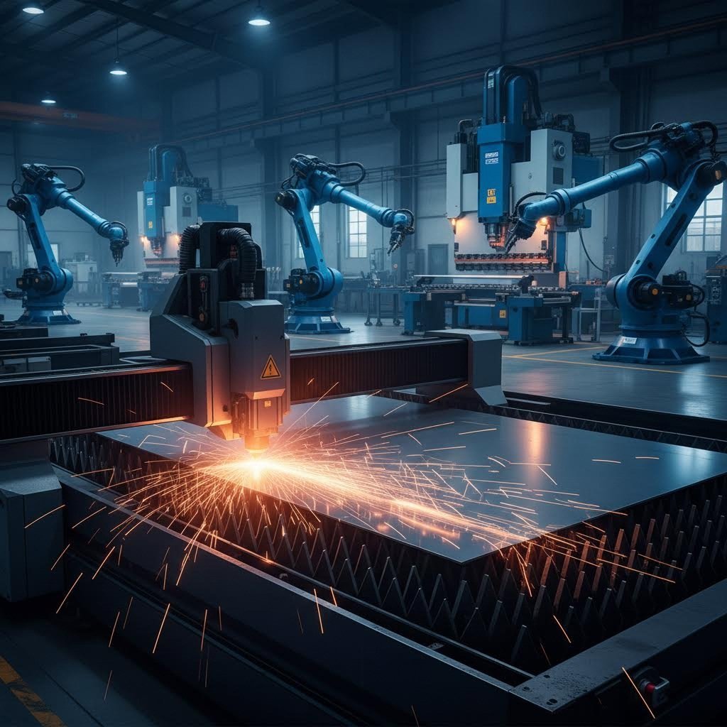
Czy kiedyś zastanawiałeś się, jak powstaje elegancka metalowa obudowa Twojego komputera lub elementy konstrukcyjne pojazdu? Odpowiedź tkwi w produkcji blach – podstawowym procesie przemysłowym który przekształca płaskie arkusze metalu w precyzyjnie zaprojektowane części stosowane w niezliczonych zastosowaniach.
Produkcja blach to proces tworzenia arkuszy metalowych z surowców w dużą skalę, obejmujący dobór metalu, walcowanie, cięcie, tłoczenie i wykańczanie, w wyniku którego powstają arkusze o grubości zazwyczaj od 0,5 mm do 6 mm.
Zrozumienie, czym jest blacha, zaczyna się od rozpoznania jej unikalnej pozycji w rodzinie metali. Blacha ma określony zakres grubości, który odróżnia ją od innych form metalu. Wszystko cieńsze niż 0,5 mm klasyfikowane jest jako folia metalowa, podczas gdy elementy grubsze niż 6 mm stają się blachą płytową. To rozróżnienie nie jest przypadkowe – fundamentalnie wpływa ono na to, które procesy i zastosowania są odpowiednie dla każdego typu materiału.
Od surowego metalu do precyzyjnych części
Znaczenie blachy wykracza poza proste określenie. Reprezentuje ona punkt wyjścia dla skomplikowanej drogi przez wiele etapów produkcji. Wyobraź sobie, że bierzesz surową stal, aluminium lub miedź i systematycznie przekształcasz je w precyzyjne komponenty, które widzisz w codziennych produktach – od instalacji wentylacyjnych po elementy szkieletu samochodowego.
Ten proces obejmuje kilka kluczowych etapów: wybór odpowiedniego metalu podstawowego, walcowanie w celu uzyskania żądanej grubości, cięcie na łatwe do zarządzania rozmiary oraz naniesienie powłok ochronnych w celu zapewnienia trwałości. Każdy etap opiera się na poprzednim, tworząc fundament dla kolejnych kroków w procesie produkcyjnym.
Dlaczego grubość określa proces
Jaka zatem cecha blachy jest najważniejsza? Grubość. Ten pojedynczy parametr decyduje o wszystkim – od technik kształtowania, które można zastosować, po wydajność konstrukcyjną końcowego produktu. Inżynierowie i specjaliści ds. zakupów polegają na pomiarach wgłębnikowych, aby dokładnie określić swoje potrzeby.
Oto coś, co często zaskakuje nowych użytkowników: numery gatunków działają odwrotnie. Mniejszy numer gatunku oznacza grubszy metal. Na przykład standardowa stal 10-gauge ma grubość około 3,4 mm, podczas gdy 20-gauge ma tylko 0,9 mm. Różne metale mają również różne zależności między numerem gatunku a grubością — ten sam numer gatunku daje inną rzeczywistą grubość dla stali i aluminium.
Zanim przejdziemy dalej, wyjaśnijmy częsty punkt niejasności: obróbka vs produkcja. Te terminy są często używane zamiennie, ale reprezentują odrębne procesy. Produkcja blach skupia się na tworzeniu samych surowych blach poprzez masową produkcję. Czym więc jest obróbka blach? Jest to kolejny proces przekształcania wyprodukowanych blach w niestandardowe komponenty poprzez cięcie, gięcie, spawanie i montaż do konkretnych zastosowań przemysłowych.
W kolejnych sekcjach dowiesz się, jak dobrać odpowiednie materiały do projektu, poznasz podstawowe procesy kształtowania i cięcia, zrozumiesz kompletny cykl produkcji oraz zasady projektowania pozwalające obniżyć koszty i poprawić jakość. Niezależnie od tego, czy dobierasz elementy do zastosowań motoryzacyjnych, czy zakupujesz komponenty na obudowy elektroniczne, niniejszy przewodnik dostarcza kluczowej wiedzy potrzebnej do podjęcia świadomych decyzji.
Przewodnik wyboru materiału dla projektów z blachy
Wybór odpowiedniego materiału blachy może wydawać się przytłaczający, gdy patrzy się na listę dostępnych opcji. Stal, aluminium, stal nierdzewna, miedź, mosiądz – każdy z tych materiałów oferuje inne zalety. Jednak o czym większość przewodników milczy: skuteczny wybór materiału nie polega na wybraniu „najlepszej” opcji. Chodzi o dopasowanie konkretnych właściwości materiału do wymagań eksploatacyjnych danej aplikacji.
Przy ocenie materiałów produkcyjnych trzeba wziąć pod uwagę kilka powiązanych ze sobą czynników: wytrzymałość mechaniczną, odporność na korozję, formowalność, ograniczenia wagi, właściwości termiczne i tak - koszt. Przeanalizujmy, jak te kryteria mają zastosowanie do wszystkich opcji blach metalowych dostępnych dla Twoich projektów.
Zastosowanie materiałów do wymagań wydajności
Pomyśl, co twoja gotowa część naprawdę musi osiągnąć. Czy wytrzyma ciężkie ładunki? W trudnych warunkach środowiskowych? Przewodzą elektryczność czy ciepło? Odpowiedzi na te pytania znacznie ograniczą wybór.
W przypadku zastosowań wymagających wytrzymałości i trwałości stali pozostaje wybór. W produkcji stali miękkiej dominuje budownictwo, przemysł motoryzacyjny i ogólna produkcja, ponieważ zapewnia doskonałą wydajność strukturalną w konkurencyjnych cenach. Stal niskoemisyjna, taka jak DC01, zapewnia lepszą formowalność dla złożonych zakrętów, podczas gdy warianty o wyższym poziomie węgla zapewniają zwiększoną twardość w zastosowaniach odpornych na zużycie.
Wykonanie blach z aluminium doskonale sprawdza się tam, gdzie liczy się redukcja masy. Ze względu na współczynnik wytrzymałości do masy około dwa razy większy niż u stali, aluminium pozwala projektować konstrukcje przenoszące porównywalne obciążenia przy połowie masy. Producenci elektroniki wybierają aluminium właśnie z tego powodu – dodatkowo jego doskonała przewodność cieplna pomaga odprowadzać ciepło od wrażliwych komponentów.
Stal nierdzewna łączy w sobie wiele wymagań. Zawartość chromu (zazwyczaj 10–30%) tworzy samo naprawiającą się warstwę tlenową, która zapobiega korozji bez potrzeby dodatkowych powłok. Gatyunki takie jak 304 i 316 są podstawowymi materiałami w przetwórstwie spożywczym, sprzęcie medycznym oraz zastosowaniach morskich, gdzie ważne są zarówno higiena, jak i trwałość.
Wykonanie blach miedzianych służy specjalistycznym zastosowaniom, gdzie priorytetem jest przewodność elektryczna lub termiczna. Miedź znajduje zastosowanie w szynach elektrycznych, wymiennikach ciepła oraz w dachówkach, gdzie jej naturalna patyna zapewnia zarówno ochronę, jak i estetyczny wygląd. Mosiądz – stop miedzi z cynkiem – oferuje podobne korzyści, lepszą obrabialność i charakterystyczny złoty wygląd.
Poza kosztem – co naprawdę decyduje o wyborze materiału
Właśnie tutaj wiele zespołów projektowych popełnia błąd: nadmierny nacisk na cenę materiału za kilogram przy jednoczesnym ignorowaniu całkowitych kosztów cyklu życia. Tani materiał blacharski, który wymaga dodatkowego wykończenia, ulega przedwczesnemu korozji lub zwiększa wagę pojazdu, może szybko okazać się rozwiązaniem droższym.
Rozważ zastosowania w przemyśle motocyklowym. Dlaczego producenci preferują konkretne gatunki stali do elementów nadwozia i zawieszenia? Sprawa sprowadza się do precyzyjnego balansu: stale o wysokiej wytrzymałości i niskiej stopowej (HSLA) zapewniają integralność konstrukcyjną niezbędną dla bezpieczeństwa, pozostając przy tym spawalne i kształtowalne. Wybór materiału ma bezpośredni wpływ na wydajność w przypadku zderzeń, zużycie paliwa oraz złożoność procesu produkcyjnego.
Obudowy elektroniczne opowiadają inną historię. Tutaj kombinacja aluminium – lekkiej konstrukcji, zdolności osłaniania przed zakłóceniami elektromagnetycznymi (EMI) oraz doskonałego odprowadzania ciepła – czyni je preferowanym materiałem blacharskim. Nieco wyższy koszt materiału przekłada się na korzyści w zarządzaniu temperaturą i wydajności produktu.
| Typ materiału | Typowe zastosowania | Ocena formowania | Odporność na korozję | Poziom kosztów |
|---|---|---|---|---|
| Stal konstrukcyjna (DC01, S235JR) | Płyty samochodowe, obudowy, uchwyty, kanały wentylacyjne | Doskonały | Niska - wymaga powłoki | $ |
| Aluminium (5052, 6061) | Obudowy elektroniczne, elementy lotnicze, wyposażenie morskie | Dobra do bardzo dobrej | Wysoka - naturalna warstwa tlenkowa | $$ |
| Stal nierdzewna (304, 316) | Sprzęt spożywczy, urządzenia medyczne, elementy architektoniczne | Umiarkowany | Doskonały | $$$ |
| Miedź | Komponenty elektryczne, wymienniki ciepła, dachy dekoracyjne | Dobre | Wysoki - tworzy patynę | $$$$ |
| Mosiądz | Elementy dekoracyjne, armatura sanitarna, instrumenty muzyczne | Dobre | Umiarkowany do wysokiego | $$$ |
Wybór grubości idzie w parze z wyborem materiału. Typowe materiały blachowe mają zazwyczaj grubość od 0,5 mm do 6 mm, przy czym specyfikacja kalibru zależy od rodzaju metalu. Płaszczy karoserii samochodowych wykonuje się najczęściej z blachy stalowej o grubości od 0,7 mm do 1,0 mm, natomiast uchwyty konstrukcyjne mogą wymagać grubości od 2 mm do 3 mm. Obudowy elektroniczne często są wykonywane z aluminium o grubości od 1 mm do 2 mm, zapewniając wystarczającą sztywność bez nadmiernego ciężaru.
Rozważania dotyczące temperatury dodają kolejny aspekt do procesu decyzyjnego. Stal nierdzewna zachowuje integralność strukturalną do około 1400°C, podczas gdy aluminium mięknie w okolicach 660°C. Z drugiej strony, aluminium faktycznie zyskuje wytrzymałość na rozciąganie w zimnych środowiskach, w których stal staje się krucha – jest to kluczowy czynnik w zastosowaniach lotniczych i kriogenicznych.
Po wybraniu materiału kolejzymy krok polega na zrozumieniu, które procesy produkcyjne przekształcą ten surowy arkusz w gotowy komponent. Metody cięcia i kształtowania, które wybierzesz, zależą bezpośrednio od właściwości materiału, które właśnie omówiliśmy.
Wyjaśnione podstawowe procesy produkcyjne
Teraz, gdy wybrałeś już materiał, rozpoczyna się właściwa transformacja. Techniki Fabrykacji Blach Metali dzielą się na dwie podstawowe kategorie: procesy cięcia, w których usuwany jest materiał w celu utworzenia podstawowego kształtu, oraz operacje kształtowania, które nadają materiałowi trójwymiarową formę. Wybór odpowiedniej kombinacji tych procesów decyduje o wszystkim – od dokładności elementu po koszty produkcji.
Oto co czyni tę decyzję trudną: rzadko istnieje jedna „najlepsza” metoda. Każda z nich doskonale sprawdza się w określonych warunkach, a zrozumienie tych warunków pozwala podejmować lepsze decyzje produkcyjne.
Porównanie technologii cięcia
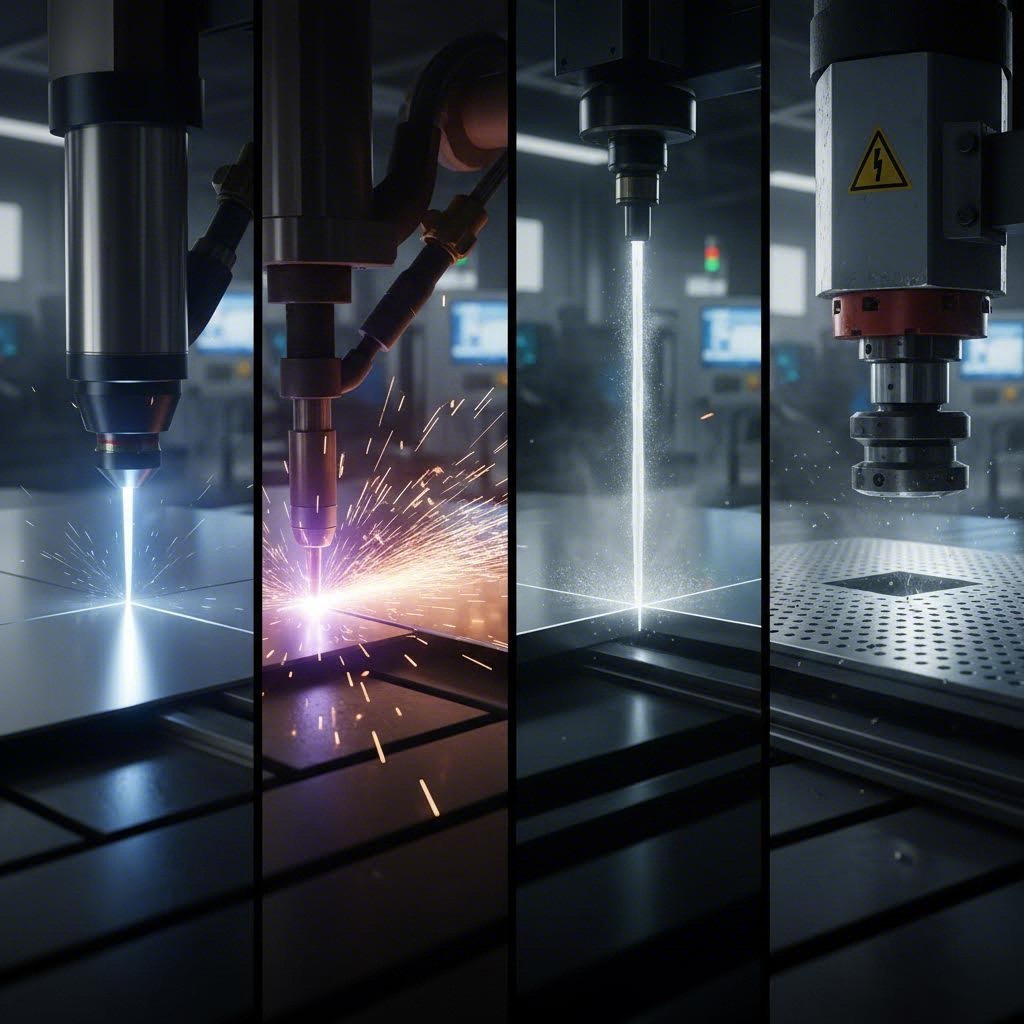
Najczęściej w pierwszym etapie produkcji wykonuje się cięcie - usuwanie nadmiaru materiału, aby stworzyć profil, który później stanie się gotowym elementem. W nowoczesnym cięciu blach dominują cztery podstawowe technologie, z których każda ma swoje mocne strony.
Cięcie laserowe
Laser koncentruje intensywne światło, aby cięć z chirurgiczną precyzją. Kiedy potrzebujesz czystych krawędzi, małych dziur lub skomplikowanych kształtów, laser jest najlepszym rozwiązaniem. Główna wiązka tworzy wyjątkowo czyste cięcia z minimalnym post-procesowania potrzebne.
- Zalety: Wyższa jakość krawędzi i precyzja; minimalna strefa cieplna na cienkich materiałach; doskonała dla złożonych geometrii i ciasnych tolerancji; duża prędkość na materiałach poniżej 6 mm; czyste cięcia często nie wymagają wtórnego wykończenia
- Ograniczenia: Problemy z materiałami o grubości powyżej 25 mm; wyższe koszty wyposażenia; materiały odblaskowe, takie jak miedź i mosiądz, wymagają lasera włóknistego; nie nadaje się do wszystkich typów materiałów
- Najlepsze zastosowania: Obudowy elektroniczne, urządzenia medyczne, uchwyty precyzyjne, panele dekoracyjne
Cięcie plazmowe
Cięcie plazmowe wykorzystuje łuk elektryczny i sprężone gazy do stapiania i usuwania przewodzących metali. Jeśli ciętnie płyty stalowe o grubości 12 mm lub większej, plazma oferuje najlepszą szybkość i efektywność kosztową .
- Zalety: Największa prędkość cięcia przy grubyh metalach; najniższy koszt eksploatacji dla grubych płyt; obsługuje materiały do 150 mm; doskonałe do stali konstrukcyjnej i ciężkiej produkcji
- Ograniczenia: Większa strefa wpływu ciepła niż przy laserze; szersza szczelina cięcia zmniejsza dokładność; działa tylko na materiałach przewodzących; krawędzie mogą wymagać szlifowania w precyzyjnych zastosowaniach
- Najlepsze zastosowania: Produkcja konstrukcji stalowych, produkcja sprzętu ciężkiego, budownictwo okrętowe, instalacje wentylacyjne
Wycinanie wodne
Systemy waterjet wykorzystują wodę pod wysokim ciśnieniem w połączeniu z ścierniwem do cięcia praktycznie dowolnego materiału bez użycia ciepła. Oznacza to brak odkształceni, brak utwardzania i brak stref wpływu ciepła – kluczowe w zastosowaniach wrażliwych na ciepło.
- Zalety: Cięcie dowolnych materiałów, w tym kompozytów, szkła i kamienia; brak odkształceń termicznych; brak utwardzania materiału; doskonała jakość krawędzi; idealne do obróbki blach, które nie mogą być narażone na ciepło
- Ograniczenia: Wolniejsze prędkości cięcia niż przy plazmie lub laserze; wyższe koszty eksploatacji ze względu na zużycie ścierniwa; inwestycja w sprzęt około 2-krotnie wyższa niż w systemy laserowe; nieopłacalne dla prostych cięć dużych serii
- Najlepsze zastosowania: Elementy lotnicze wymagające braku oddziaływania temperatury, części z tytanu, materiały kompozytowe, urządzenia przemysłu spożywczego
Przebijanie mechaniczne
Klipsowanie wykorzystuje hartowane stalowe matryce do ścinania materiału, tworząc otwory i kształty poprzez bezpośrednią siłę mechaniczną. Dla produkcji seryjnej standardowych kształtów klipsowanie oferuje nieosiągalną wcześniej szybkość i opłacalność.
- Zalety: Najszybszy proces dla powtarzalnych elementów; najniższy koszt na sztukę przy dużych seriach; może wykonywać operacje kształtowania jednocześnie; minimalne odpady materiałowe
- Ograniczenia: Wymaga inwestycji w oprzyrządowanie dla każdego kształtu; ograniczone do grubości materiału zazwyczaj poniżej 6 mm; mniejsza elastyczność w zakresie zmian projektowych; zużycie narzędzi wpływa na dokładność w czasie
- Najlepsze zastosowania: Obudowy elektryczne ze stałymi wzorami otworów, uchwyty samochodowe, panele urządzeń gospodarstwa domowego, kratki wentylacyjne
Metody kształtowania wpływające na projekt
Gdy już wycięto płaski wykrojnik, proces gięcia blachy przekształca dwuwymiarowe kształty w funkcjonalne elementy trójwymiarowe. Każda operacja kształtowania powoduje kontrolowaną deformację, aby osiągnąć określone geometrie.
Zgięcie
Gięcie zmienia kształt płaskiej blachy na kąty, zakładki lub krzywe bez zmiany grubości materiału. Jest to najczęstsza operacja gięcia blachy, stosowana niemal we wszystkich wyrobach spawanych.
- Zalety: Proste wymagania dotyczące oprzyrządowania; krótkie czasy cyklu; zachowana grubość materiału; odpowiednie od prototypów po produkcję seryjną
- Ograniczenia: Efekt sprężystego odkształcenia wymaga kompensacji w narzędziu; minimalny promień gięcia zależy od materiału i grubości; rozmieszczenie otworów w pobliżu gięć wymaga starannego projektowania
- Kluczowe zagadnienia: Należy obliczyć zapas gięcia, kompensację efektu sprężystego odkształcenia oraz minimalny promień gięcia, aby zapobiec pęknięciom
Pieczętowanie
Proces tłoczenia blach obejmuje kształtowanie metalu za pomocą matryc i tłoków przy użyciu technik takich jak przebijanie, gięcie, tłoczenie powierzchniowe i koining – często łączone w matrycach progresywnych wykonujących wiele operacji po kolei
- Zalety: Wysoka prędkość produkcji umożliwia produkcję seryjną; niższy koszt pojedynczego elementu w dużych seriach; szeroka kompatybilność z materiałami, w tym stalą, aluminium i tworzywami sztucznymi; stała powtarzalność
- Ograniczenia: Duże nakłady inwestycyjne w narzędzia; mniej odpowiedni dla części o głębokich lub skomplikowanych geometriach; zmiany konstrukcyjne wymagają nowych narzędzi; pewna ilość odpadów materiału w operacjach progresywnych
- Najlepsze zastosowania: Elementy karoserii samochodowej, wsporniki, zaczepy, komponenty urządzeń gospodarstwa domowego, styki elektryczne
Głębgłębnego wyciągania
Wykrawanie głębokie wprowadza blachę do wnęki matrycy, tworząc trójwymiarowe kształty o głębokości przekraczającej średnicę otworu. Przykłady to zbiorniki paliwa w pojazdach samochodowych, zlewy kuchenne oraz puszki na napoje.
- Zalety: Tworzy skomplikowane kształty wklęsłe, niemożliwe do uzyskania innymi metodami; doskonała efektywność materiału przy minimalnych odpadach; elementy charakteryzują się zwiększoną wytrzymałością dzięki odkształceniowi plastycznemu na zimno
- Ograniczenia: Wyższe początkowe koszty narzędzi; wymaga materiałów o dużej ciągliwości; wolniejsze czasy cyklu niż tłoczenie; nieopłacalne dla małych serii produkcyjnych
- Najlepsze zastosowania: Elementy samochodowe, pojemniki przemysłowe, naczynia kuchenne, obudowy lotnicze
Formowanie na wałkach
Profilowanie przez walcowanie przepuszcza blachę przez kolejne matryce rolkowe, stopniowo kształtując ciągłe profile – idealne dla długich elementów o stałym przekroju.
- Zalety: Bardzo efektywne dla długich części; spójny profil na całej długości; wysokie prędkości produkcji; minimalne zużycie materiału
- Ograniczenia: Ograniczone do stałych przekrojów; znaczne nakłady związane z przygotowaniem produkcji; nieodpowiednie dla krótkich serii lub zmiennych profili
- Najlepsze zastosowania: Ramy konstrukcyjne, wykończenia samochodowe, panele dachowe, systemy półek
Wybór odpowiedniego procesu
Wybór procesu zależy od czterech powiązanych ze sobą czynników:
- Rodzaj materiału: Kucie aluminium nadaje się do głębokiego tłoczenia; wytrzymałość stali radzi sobie z tłoczeniem wysokotonażowym; wrażliwe na ciepło stopy wymagają cięcia strumieniem wody
- Grubość: Cienkie blachy (poniżej 3 mm) najlepiej ciąć laserem; grube płyty (powyżej 12 mm) lepiej ciąć plazmą; wymagania dotyczące siły tłoczenia rosną wykładniczo wraz z grubością
- Objętość produkcji: Niskie serie uzasadniają zastosowanie elastycznych procesów, takich jak cięcie laserowe i gięcie na prasie; duże serie wymagają inwestycji w narzędzia do tłoczenia i matryce progresywne
- Wymagania dotyczące dokładności: Wysoka dokładność richi wymaga cięcia laserowego zamiast plazmy; precyzyjne kąty gięcia wymagają kompensacji narzędziowej na skok sprężysty
Zrozumienie tych operacji kształtowania blach i technologii cięcia daje podstawę do oceny opcji produkcyjnych. Jednak znajomość procesów to dopiero początek – dalej zobaczysz, jak te operacje łączą się w kompletnym cyklu produkcji, który przekształca surowiec w gotowe komponenty.
Kompletny Cykl Produkcji Blach
Wybrałeś materiał i znasz podstawowe procesy. Ale jak te elementy łączą się w rzeczywistej produkcji? Jak powstaje komponent z blachy – od początkowego założenia po gotowy element gotowy do montażu?
Proces obróbki blach przebiega według przewidywalnej sekwencji – siedem odrębnych etapów, które budują się jeden na drugim. Zrozumienie tego cyklu pomaga przewidzieć czas realizacji, zidentyfikować źródła problemów oraz skutecznie komunikować się z partnerami produkcyjnymi.
Siedem Etapów Produkcji
Każdy proces produkcji blach follows tej podstawowej sekwencji, choć konkretne kroki mogą się nakładać lub powtarzać w zależności od złożoności elementu:
-
Projekt i Inżynieria
Wszystko zaczyna się od szczegółowego planu. Inżynierowie pracują z oprogramowaniem CAD, tworząc precyzyjne modele 3D określające dokładne wymiary, specyfikacje materiałów i tolerancje. Ten etap decyduje o wykonalności – czy możliwe jest faktycznie wyprodukowanie elementu dostępnymi procesami? Tutaj podejmowane są kluczowe decyzje dotyczące promieni gięcia, rozmieszczenia otworów i grubości materiału. Tolerancje zwykle wahają się od ±0,1 mm dla precyzyjnych elementów ciętych laserowo do ±0,5 mm dla wymiarów kształtowanych. Błędy popełnione na tym etapie mają wpływ na wszystkie kolejne kroki. -
Zakup Materiałów
Po zatwierdzeniu projektu należy pozyskać odpowiedni materiał blacharski. Obejmuje to dopasowanie specyfikacji gatunku, zweryfikowanie tolerancji grubości oraz potwierdzenie certyfikatów materiału. W zastosowaniach motoryzacyjnych wymagana jest pełna śledzalność materiału. Wpływ czasu realizacji: standardowe materiały są wysyłane w ciągu kilku dni, podczas gdy specjalistyczne stopy mogą wymagać kilku tygodni. Opóźnienia w zakupach to jedna z najczęstszych przyczyn przekroczenia harmonogramu projektu. -
Cięcie
Surowe arkusze przekształca się w płaskie заготовki za pomocą cięcia laserowego, plazmowego, wodno-ściernej lub mechanicznego. Metoda cięcia ma bezpośredni wpływ na jakość krawędzi i dalsze procesy technologiczne. Krawędzie cięte laserowo zazwyczaj nie wymagają dodatkowego wykończenia, podczas gdy elementy cięte plazmą mogą potrzebować szlifowania przed spawaniem. Dokładność wymiarowa na tym etapie powinna mieścić się w granicach od ±0,1 mm do ±0,25 mm, w zależności od wybranej metody. -
Tworzenie
Płaskie заготовки przekształcają się w trójwymiarowe komponenty poprzez gięcie, tłoczenie lub wykrojnikowanie. To właśnie tutaj najbardziej widoczny jest sposób produkcji blach — materiał płaski fizycznie zmienia się w rozpoznawalne części. Kompensacja odbicia, obliczana podczas projektowania, zostaje zweryfikowana na tym etapie. Tolerancje kształtowania mieszczą się zazwyczaj w zakresie ±0,25 mm do ±0,5 mm dla położeń gięcia oraz ±0,5° do ±1° dla kątów gięcia. -
Łączenie i montaż
Poszczególne komponenty są łączone poprzez spawanie, nitowanie, dokręcanie lub klejenie. Jakość spoin ma bezpośredni wpływ na integralność konstrukcyjną i wygląd. W przypadku zastosowań krytycznych procedury spawania muszą być zakwalifikowane, a spawacze certyfikowani. Kolejność montażu ma znaczenie – nieprawidłowa kolejność może utrudnić dostęp lub spowodować odkształcenia wynikające z ciepła spawania. -
Wykończenie powierzchni
Surowe wyroby często posiadają ślady spawania, odbarwienia lub wady powierzchniowe wymagające obróbki. Operacje wykańczające obejmują szlifowanie, polerowanie, malowanie proszkowe, powlekanie galwaniczne lub lakierowanie. Rodzaj wykończenia wpływa zarówno na wygląd, jak i na właściwości użytkowe – odporność na korozję, przewodność elektryczną oraz odporność na zużycie zależą od odpowiedniego przygotowania powierzchni. -
Kontrola jakości
Ostateczna weryfikacja zapewnia zgodność elementów ze wszystkimi specyfikacjami. Metody kontroli obejmują sprawdzenie wzrokowe aż po weryfikację za pomocą maszyny pomiarowej CMM dla krytycznych wymiarów. Zaawansowani producenci osiągają dokładność wymiarów rzędu 0,003–0,005 cala (0,076–0,127 mm) w zastosowaniach precyzyjnych. Do ukończonych części dołączane są dokumenty, w tym raporty pomiarowe oraz certyfikaty materiałów.
Jakość, która jest wbudowana
Oto czego doświadczeni inżynierowie dobrze rozumieją: jakości nie da się sprawdzić w ostatnim etapie – jest ona wbudowywana na każdym etapie produkcji. Problemy wykrywane podczas końcowej inspekcji często wynikają z decyzji podjętych wcześniej.
Typowe problemy i ich przyczyny:
- Części nie mogą być poprawnie złożone → Zwykle wynika to z projektu (niedokładności tolerancji) lub kształtowania (błędna kalkulacja sprężystego odkształcenia)
- Pęknięcia podczas procesu kształtowania → Problem związany z doborem materiału lub projektem (zbyt mały promień gięcia w stosunku do grubości materiału)
- Awaria spoin → Problemy z projektem złącza, przygotowaniem materiału lub kwalifikacjami spawacza
- Korozja podczas eksploatacji → Specyfikacja wykończenia nieadekwatna do warunków środowiskowych lub błędnego wykonania procesu wykończenia
Czas realizacji całego procesu produkcji blacharskiej znacznie zależy od stopnia skomplikowania, wielkości partii oraz aktualnej dostępności maszyn w zakładzie. Proste elementy mogą być wykonane w ciągu 5–10 dni roboczych. Skomplikowane zespoły wymagające specjalnych narzędzi mogą potrzebować 6–8 tygodni lub dłużej. Prototypy są zwykle realizowane szybciej niż serie produkcyjne, ponieważ nie wymagają opracowania narzędzi.
Czynniki wpływające na harmonogram produkcji:
- Złożoność projektu i liczba wymaganych operacji
- Dostępność materiałów – standardowe a specjalne gatunki
- Wymagania dotyczące narzędzi – istniejące a niestandardowe matryce
- Wymagania dotyczące wykończenia i czasy utwardzania
- Wymagania dotyczące inspekcji i potrzeby dokumentacyjne
- Obciążenie warsztatu i harmonogramowanie
Integracja CAD/CAM zrewolucjonizowała sposób produkcji blach w nowoczesnych zakładach. Bezproblemowe połączenie między oprogramowaniem projektowym a sprzętem produkcyjnym eliminuje ręczne przesyłanie danych, które wcześniej prowadziło do błędów. Gdy inżynierowie modyfikują projekt, oprogramowanie CAM automatycznie aktualizuje ścieżki cięcia i instrukcje gięcia. Ta integracja umożliwia przetwarzanie partii i optymalizację zagospodarowania – układanie wielu części na pojedynczych arkuszach w celu maksymalnego wykorzystania materiału i minimalizacji odpadów.
Oprogramowanie oblicza optymalne ścieżki narzędzi, uwzględniając możliwości narzędzi, właściwości materiału oraz parametry obróbki. Optymalizuje każdą operację w celu maksymalizacji wydajności przy zachowaniu precyzji. W przypadku złożonych operacji, takich jak obróbka wieloosiowa, symulacja CAD/CAM pozwala zidentyfikować potencjalne problemy jeszcze przed przystąpieniem do cięcia materiału – oszczędzając czas i koszty odpadów.
Gdy proces produkcyjny jest już jasno określony, pojawia się kolejne kluczowe pytanie: jak projektować części, które będą płynnie przechodzić przez poszczególne etapy bez kosztownych problemów? Właśnie tutaj zaczynają obowiązywać zasady projektowania pod kątem technologii wytwarzania.
Najlepsze praktyki projektowania pod kątem technologii wytwarzania
Ustaliłeś kompletny przebieg procesu produkcyjnego. Nadchodzi teraz pytanie, które decyduje o tym, czy produkcja potoczy się gładko, czy też przyniesie kosztowne kłopoty: czy Twój projekt jest rzeczywiście zoptymalizowany pod kątem produkcji? Projekt blacharski, który wygląda idealnie w programie CAD, może stać się prawdziwym koszmarem na hali produkcyjnej – prowadząc do pęknięć przy gięciu, odkształcanych otworów oraz elementów, których nie da się poprawnie uformować.
Wykonywanie i projektowanie metalu idą ręka w rękę. Decyzje podejmowane na etapie projektowania wpływają bezpośrednio na koszty narzędzi, poziom odpadów oraz harmonogram produkcji. Przestrzeganie sprawdzonych wytycznych projektowania blach pozwala uniknąć kosztownych poprawek i zapewnia płynny przejście od projektu do gotowego elementu.
Zasady projektowania redukujące koszty
Traktuj te wytyczne jako ubezpieczenie przed problemami produkcyjnymi. Każda z tych reguł powstała dlatego, że inżynierowie na własnej skórze przekonali się, co się dzieje, gdy podczas operacji kształtowania zaniedba się zachowanie materiału.
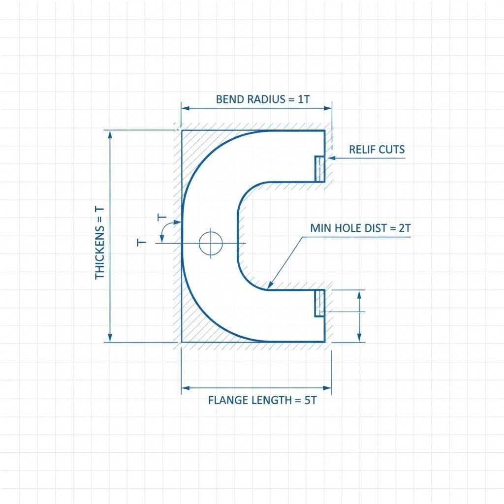
- Minimalny promień gięcia powinien być równy lub większy niż grubość materiału. Zbyt mały promień powoduje problemy z przepływem materiału u miękkich stopów, a twarde materiały pękają lub łamią się. W większości zastosowań określenie wewnętrznego promienia gięcia co najmniej równego 1× grubości materiału zapobiega lokalnemu ścienianiu. W zastosowaniach lotniczych i wysokociśnieniowych często wymagany jest promień 2× lub większy.
- Otwory należy rozmieszczać w odległości co najmniej 1,5T + promień gięcia od każdej linii gięcia. Gdy otwory znajdują się zbyt blisko gięcia, ulegają deformacji podczas procesu kształtowania - stają się owalne lub są niewyjustowane. Preferowana odległość uwzględnia zarówno grubość materiału (T), jak i promień gięcia (H), zapewniając, że otwór pozostaje poza strefą odkształcenia.
- Zachowaj odstęp między otworami co najmniej 2x grubość materiału. Otwory umieszczone zbyt blisko siebie osłabiają materiał pomiędzy nimi. Podczas gięcia lub formowania ten osłabiony fragment może ulec odkształceniom lub pęknięciu. Właściwy odstęp zachowuje integralność strukturalną i zapobiega wzajemnemu oddziaływaniu otworów.
- Wykonuj otwory większe niż grubość materiału. Średnice otworów mniejsze niż grubość blachy powodują problemy podczas przebijania — większe obciążenie narzędzi, nadmierne powstawanie zadziorów oraz bardziej szorstkie krawędzie otworów. Zachowanie średnicy otworu większej niż grubość materiału zapewnia czyste przebicie i gładkie krawędzie.
- Umieść luz gięcia na przecinających się liniach gięcia. Luz gięcia — niewielka wycięcie lub nacięcie w miejscu przecięcia się dwóch gięć — zapobiega rozrywaniu i umożliwia kontrolowany przepływ materiału . Głębokość wcięcia powinna być równa lub większa niż promień wewnętrznego zgięcia. Bez niego materiał gromadzi się i pęka w miejscu przecięcia.
- Przestrzegaj minimalnej długości płata dla Twojego materiału. Wykrojnica do giętarki musi zapewniać wystarczający kontakt po obu stronach zgięcia, aby dokładne sformowanie było możliwe. Minimalna długość płata znacznie różni się w zależności od materiału i grubości — stal nierdzewna o grubości 0,250" wymaga płatów o długości co najmniej 1,150", podczas gdy aluminium o grubości 0,040" może działać z płatami aż do 0,255".
- Umieszczaj elementy z dala od stref deformacji przy zginaniu. Wycięcia, wypukłe elementy i inne geometrie znajdujące się blisko zgięć mogą ulec wygięciu lub rozciągnięciu podczas formowania. Bezpieczna odległość zależy od typu i grubości materiału — miękkie metale łatwiej się rozciągają, podczas gdy twarde opierają się odkształceniom, ale mogą pękać.
Unikanie drogich błędów produkcyjnych
Nawet doświadczeni projektanci popełniają błędy, które utrudniają produkcję. Zrozumienie tych typowych pułapek pomaga wykryć problemy zanim trafią na halę produkcyjną.
Ignorowanie dodatku na zgięcie w rozwinięciach Gięcie powoduje rozciąganie materiału – zewnętrzna powierzchnia ulega wydłużeniu, podczas gdy wewnętrzna jest ściskana. Twój rozwinięty kształt musi uwzględniać to rozciąganie, w przeciwnym razie końcowe wymiary nie będą odpowiadać projektowi. Nowoczesne oprogramowanie CAD automatycznie oblicza kompensację gięcia, ale jedynie wtedy, gdy wprowadzisz poprawny współczynnik K dla danego materiału i wyposażenia gięciowego.
Projektowanie kolizji w skomplikowanych elementach. Elementy wielokrotnie gięte mogą powodować sytuacje, w których materiał koliduje z narzędziem lub sam ze sobą podczas formowania. Kolizje maszyn występują, gdy geometria detalu przeszkadza w pracy prasy hydraulicznej podczas gięcia. Kolizje własne mają miejsce, gdy jeden fragment elementu uderza w inny podczas kolejnych gięć. W obu przypadkach konieczna jest modyfikacja projektu lub zastosowanie specjalnego narzędzia.
Określanie niespójnych krawędzi płaszczyzn. Krawędzie żeber, które nie są równoległe do linii gięcia, powodują niestabilne podparcie podczas procesu kształtowania. Rezultat? Niespójne kąty gięcia oraz różnice wymiarowe między poszczególnymi elementami. Jeśli projekt wymaga nieregularnych krawędzi żeber, rozważ dodanie tymczasowych krawędzi odniesienia, które zostaną usunięte po zakończeniu gięcia.
Pomijanie kompensacji odbicia sprężystego. Każdy materiał lekko odbija się po gięciu – kąt gięcia zwiększa się po usunięciu nacisku. Różne materiały i grubości wykazują różne zachowanie w zakresie odbicia sprężystego. Projekt lub narzędzia muszą uwzględniać tę zależność, zazwyczaj poprzez lekkie przeświadczenie. Nieuwzględnienie odbicia sprężystego oznacza, że elementy nie będą odpowiadać określonym kątom.
Poprawne rozmieszczenie blach metalowych na etapie projektowania zmniejsza koszty narzędzi poprzez wykorzystanie standardowych możliwości, a nie konieczność tworzenia indywidualnych rozwiązań. Minimalizuje również odpady, zapobiegając awariom kształtowania i wyrzutom. Dodatkowo przyspiesza produkcję, eliminując konieczność prób i korekt na hali produkcyjnej.
Dla podstawowych projektów z blachy te wytyczne radzą sobie z większością sytuacji. Złożone elementy korzystają z kompleksowego wsparcia DFM — doświadczeni producenci mogą przejrzeć projekt i wskazać możliwości optymalizacji, zanim przystąpisz do produkcji. Wczesna współpraca pozwala wykryć problemy, które nawet doświadczonym projektantom umykają, oszczędzając czas i pieniądze na etapie wytwarzania.
Gdy projekt jest zoptymalizowany pod kątem produkcji, kolejną decyzją staje się wybór strategiczny: czy obróbka blachy jest rzeczywiście odpowiednią metodą dla danego zastosowania, czy może lepsze będą toczenie i frezowanie CNC, druk 3D lub odlewanie?
Kiedy wybrać obróbkę blachy zamiast metod alternatywnych
Projekt został zoptymalizowany pod kątem produkcji. Ale zanim podejmiesz decyzję, warto zadać pytanie: czy rzeczywiście obróbka blachy jest odpowiednią metodą dla danego zastosowania? Czasem odpowiedź brzmi wyraźne tak. Inne razy lepsze wyniki dla konkretnych wymagań mogą dać toczenie i frezowanie CNC, druk 3D lub odlewanie.
Zrozumienie różnicy między metodami produkcji a technikami obróbki — oraz kiedy każda z nich doskonale się sprawdza — pozwala uniknąć kosztownych niezgodności procesowych. Przeanalizujmy, jak obróbka blachy porównuje się do alternatyw pod względem czynników rzeczywiście istotnych dla Twojego projektu.
Blacha vs. Frezowanie CNC vs. Druk 3D
Każda metoda produkcyjna ma swoje wyraźne zalety. Prawidłowy wybór zależy od geometrii elementu, wielkości produkcji, wymagań materiałowych i ograniczeń czasowych.
| Czynnik | Wytwarzaniu blach | Obróbka CNC | drukowanie 3D | FORMOWANIE |
|---|---|---|---|---|
| Optymalny zakres wielkości produkcji | 100 do ponad 100 000 sztuk | 1 do 1000 sztuk | 1 do 100 sztuk | powyżej 10 000 części |
| Opcje materiałowe | Stal, aluminium, stal nierdzewna, miedź, mosiądz w postaci arkuszy | Prawie każdy metal, tworzywo sztuczne lub kompozyt nadający się do obróbki skrawaniem | Ograniczone metale; głównie tworzywa sztuczne i specjalistyczne stopy | Aluminium, cynk, magnez, żelazo, stopy stali |
| Możliwości precyzji | ±0,1 mm do ±0,5 mm typowe | osiągalne ±0,025 mm | ±0,1 mm do ±0,3 mm w zależności od technologii | ±0,25 mm do ±1 mm w zależności od metody |
| Struktura kosztów | Niskie koszty narzędzi; umiarkowany koszt sztuki; doskonały przy dużych nakładach | Brak narzędzi; wyższy koszt sztuki; skalowanie liniowe | Brak narzędzi; najwyższy koszt sztuki; minimalna korzyść z efektu skali | Duża inwestycja w narzędzia; najniższy koszt sztuki przy dużych nakładach |
| Terminy realizacji | 5–15 dni typowo; szybciej dla prostych elementów | Godziny do dni dla pierwszych sztuk | Godziny do dni; najszybsze dla prototypów | 6–12 tygodni na oprzyrządowanie; szybka produkcja po tym czasie |
| Najlepsze geometrie | Obudowy, uchwyty, panele, podwozia, kształtki | Bryłowe elementy 3D, złożone kieszenie, cechy gwintowane | Kształty organiczne, kanały wewnętrzne, struktury kratownicowe | Złożone bryły o kształtach z cechami wewnętrznymi |
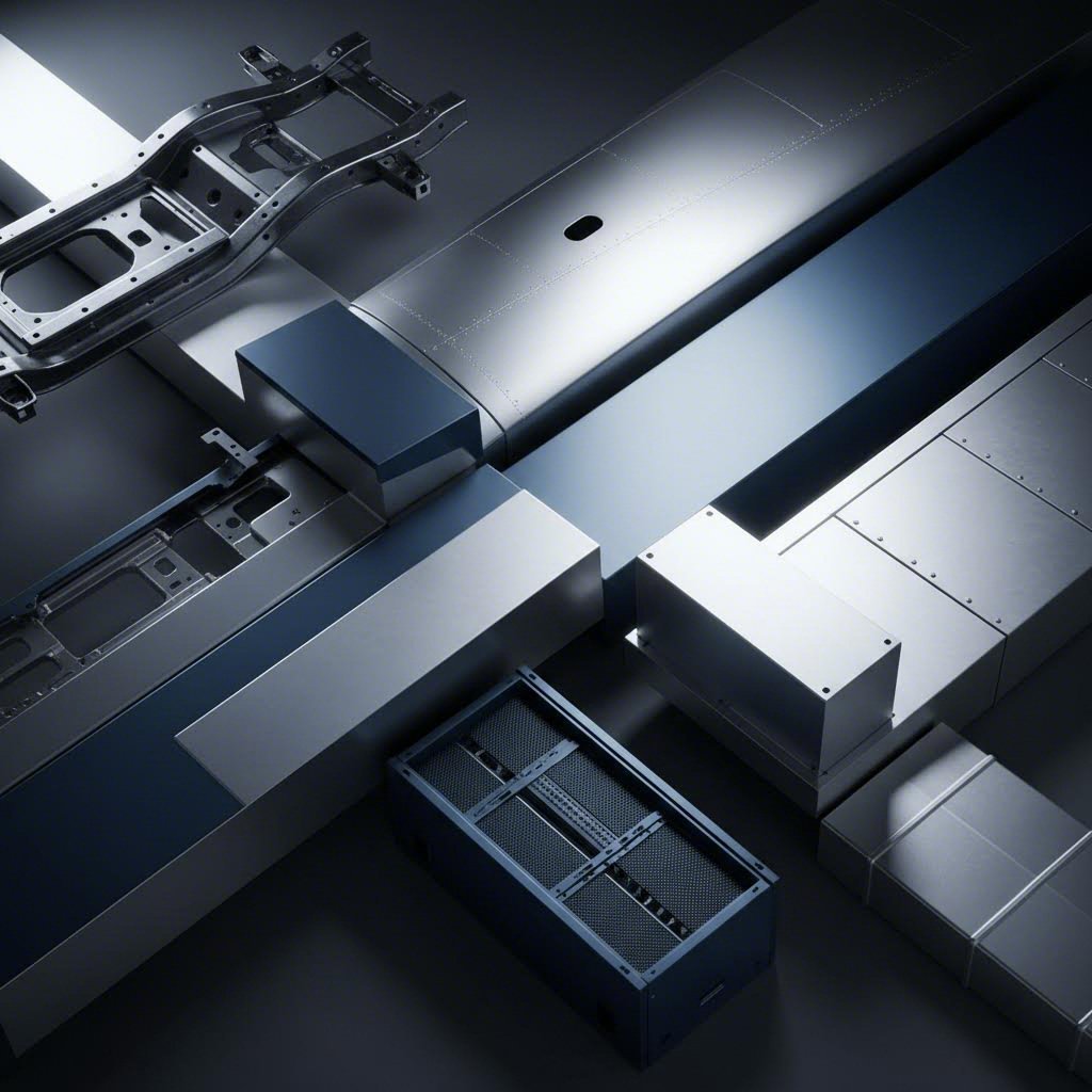
Technologia blacharska zapewnia nieosiągalną wartość dla części, które początkowo są płaskie, a następnie formowane na trójwymiarowe kształty. Obudowy, uchwyty, podwozia, panele oraz komponenty konstrukcyjne idealnie wpisują się w tę kategorię. Proces ten doskonale sprawdza się, gdy potrzebujesz:
- Konstrukcji cienkościennych o wysokim stosunku wytrzymałości do masy
- Części wymagających gięcia, zakładów lub innych formowanych cech
- Średnie do wysokich objętości produkcji, gdzie koszt sztuki ma znaczenie
- Spójna powtarzalność w dużych seriach produkcyjnych
- Komponenty, które korzystają z wewnętrznej wytrzymałości formowanego metalu
Wytwarzanie wyrobów blacharskich odgrywa kluczową rolę w produkcji elementów podwozi samochodowych, obudów elektronicznych, kanałów instalacji HVAC, paneli urządzeń gospodarstwa domowego oraz osłon sprzętu przemysłowego. Te zastosowania wykorzystują naturalne zalety pracy z materiałami blacharskimi – skuteczność konstrukcyjną, korzystny koszt w produkcji seryjnej oraz możliwość tworzenia złożonych form z prostych płaskich заготовek.
Podjęcie odpowiedniej decyzji produkcyjnej
Kiedy więc warto rozważyć rozwiązania inne niż blacha? Każda alternatywna metoda ma konkretne sytuacje, w których przewyższa technologię blacharską.
Wybierz obróbkę CNC, gdy:
- Twój detal ma stały kształt 3D, a nie jest formowaną powłoką
- Potrzebujesz bardzo dokładnych tolerancji (poniżej ±0,05 mm)
- Projekt obejmuje skomplikowane wnętrza, kieszenie lub gwintowane otwory
- Tworzysz prototypy lub małe serie (poniżej 100 sztuk)
- Wymagane są opcje materiałów poza blachami metalowymi
Frezowanie CNC zaczyna się od pełnych bloków i usuwa materiał, aby stworzyć Twoją część Pozwala szybko i ekonomicznie wytworzyć pierwsze części , co czyni je idealnym rozwiązaniem do prototypowania i produkcji małoseryjnej. Jednak obróbka numeryczna nie oferuje korzyści skali produkcyjnej, jakie daje kształtowanie – setna część kosztuje praktycznie tyle samo co pierwsza
Wybierz druk 3D, gdy:
- Geometria jest zbyt złożona dla jakiekolwiek tradycyjnej metody wytwarzania
- Potrzebujesz kanałów wewnętrznych, struktur kratowych lub organicznych kształtów
- Wymagana jest tylko jedna lub kilka sztuk
- Szybkość uzyskania pierwszej części jest ważniejsza niż koszt pojedynczej sztuki
- Iteracja projektu jest w toku, a inwestycja w formy byłaby przedwczesna
druk 3D umożliwia rzeczy niemożliwe przy procesach ubytkowych lub kształtujących. Ale istnieje kompromis: koszt pojedynczej sztuki pozostaje wysoki niezależnie od wielkości produkcji. Brakuje korzyści skali – wydrukowanie 1000 identycznych elementów kosztuje niemal 1000 razy więcej niż wydrukowanie jednego. W przypadku partii produkcyjnych addytywne metody wytwarzania rzadko są opłacalne.
Wybierz odlewanie, gdy:
- Wielkość produkcji przekracza 10 000 sztuk
- Wymagane są złożone bryły stałe z wewnętrznymi detalami
- Koszt pojedynczej sztuki jest głównym czynnikiem decydującym
- Możesz pogodzić się z czasem realizacji form od 6 do 12 tygodni
- Geometria części pozostaje stabilna (zmiany form są kosztowne)
Odlewanie odwraca zależność kosztów w porównaniu z obróbką skrawaniem. Wykonanie matrycy zajmuje czas, ale każdy odlew można wyprodukować szybko i przy stosunkowo niskim koszcie jednostkowym. Dla dziesiątek tysięcy sztuk i więcej, odlewanie staje się znacznie bardziej opłacalne niż jakakolwiek alternatywa
Oto praktyczny schemat decyzyjny, który pomoże w podjęciu wyboru:
- Zacznij od geometrii. Czy Twój element ma postać formowanej powłoki czy bryły stałej? Struktury powłokowe lepiej sprawdzają się w blacharstwie; elementy masywne — w obróbce skrawaniem lub odlewnictwie.
- Weź pod uwagę objętość produkcji. Mniej niż 100 sztuk? Obróbka skrawaniem lub druk 3D. Od 100 do 10 000 sztuk? Technologia blacharzana. Powyżej 10 000 sztuk? Rozważ odlewanie w połączeniu z tłoczeniem wysokoseriowym.
- Weź pod uwagę harmonogram. Potrzebujesz części już w tym tygodniu? Obróbka skrawaniem i druk 3D są najszybsze. Możesz poczekać na oprzyrządowanie? Odlewanie i tłoczenie matrycowe oferują najniższe koszty długoterminowe.
- Oceń całkowity koszt. Nie porównuj tylko ofert cenowych — uwzględnij amortyzację oprzyrządowania, operacje wtórne oraz koszt potencjalnych przebudów konstrukcji.
Decyzja między wytworzeniem a produkcją często nie jest binarna. Wiele produktów łączy wiele procesów — obudowy blacharskie z obrabianymi wspornikami montażowymi, odlewane korpusy z pokrywami blacharskimi, prototypy drukowane w 3D weryfikowane przed przejściem do narzędzi produkcyjnych. Sprytne strategie produkcji wykorzystują każdy proces tam, gdzie przynoszą one największą wartość.
Gdy już potwierdzisz, że blacharstwo jest odpowiednie dla Twojego zastosowania, pojawia się kolejne pytanie: które branże i zastosowania najbardziej skorzystają z tego wszechstronnego procesu? Zrozumienie rzeczywistych przypadków użycia pomaga porównać własne wymagania z sprawdzonymi rozwiązaniami.
Zastosowania przemysłowe i przykłady użycia w praktyce
Potwierdziłeś, że blacharstwo jest odpowiednim wyborem produkcyjnym. Ale oto co zmienia tę decyzję z teoretycznej na praktyczną: zrozumienie, w jaki sposób różne branże wykorzystują ten proces – i dlaczego. Przemysł produkcji wyrobów z blachy obsługuje niemal każdy sektor współczesnej gospodarki, jednak każde zastosowanie wymaga konkretnych właściwości materiału, dokładności wykonania oraz certyfikatów.
Co czyni przemysł blacharski tak uniwersalnym? To wynika z unikalnego połączenia właściwości, jakie zapewnia formowanie metalu: wysoka wytrzymałość przy niewielkiej wadze, doskonała kształtowność, opłacalność produkcji seryjnej oraz możliwość tworzenia złożonych obudów i elementów konstrukcyjnych z prostych płaskich заготовek. Spójrzmy, jak te zalety przejawiają się w rzeczywistych zastosowaniach w kluczowych branżach.
Zastosowania i wymagania w przemyśle motoryzacyjnym
Sektor motoryzacyjny stanowi jednego z największych globalnych odbiorców komponentów blacharskich. Od paneli karoseryjnych po wzmocnienia konstrukcyjne, produkcja elementów metalowych stanowi podstawę bezpieczeństwa, wydajności i estetyki pojazdów.
Dlaczego przemysł motoryzacyjny tak bardzo preferuje blachę? Odpowiedź tkwi w stosunku wytrzymałości do wagi. Nowoczesne pojazdy muszą spełniać coraz bardziej rygorystyczne normy dotyczące zużycia paliwa i emisji, zachowując jednocześnie odporność na zderzenia. Stale o wysokiej wytrzymałości i niskim stopie (HSLA) oraz zaawansowane stopy aluminium zapewniają niezbędną integralność konstrukcyjną dla bezpieczeństwa, nie dodając przy tym nadmiernej wagi, która pogarsza oszczędność paliwa.
Elementy podwozia i zawieszenia są przykładem przemysłowego gięcia blach w najbardziej wymagających zastosowaniach. Produkcja ramion kierowniczych, elementów zawieszenia oraz konstrukcyjnych części podwozia wymaga precyzyjnych tolerancji inżynieryjnych i spójnej jakości przy dużych seriach produkcyjnych. Te komponenty bezpośrednio wpływają na właściwości jezdne pojazdu, bezpieczeństwo i trwałość – nie ma miejsca na wady produkcyjne.
- Panele nadwozia: Drzwi, maski, nadkola i fragmenty dachu formowane z blach stalowych lub aluminiowych
- Elementy konstrukcyjne: Podłogi, poprzeczki i wsporniki wzmacniające
- Części podwozia: Ramiona sterujące, wahacze, mocowania zawieszenia oraz zespoły ramy nośnej
- Wsporniki wnętrza: Ramy siedzeń, podpory deski rozdzielczej i konstrukcje mocujące konsolę
- Systemy wydechowe: Osłony cieplne, uchwyty montażowe i obudowy konstrukcyjne
Certyfikacja jakości ma ogromne znaczenie w zastosowaniach motoryzacyjnych. Certyfikat IATF 16949 – międzynarodowy standard zarządzania jakością opracowany przez International Automotive Task Force – stanowi punkt odniesienia w branży. Ten certyfikat gwarantuje, że producenci utrzymują rygorystyczne systemy jakości obejmujące wszystko, od śledzenia materiałów po kontrolę statystyczną procesów. Podczas zakupu blach stalowych do przemysłu motoryzacyjnego, certyfikat IATF 16949 od partnera produkcyjnego nie jest opcjonalny – to podstawowe wymaganie większości producentów OEM i dostawców z pierwszego szczebla.
Producentów, takich jak Shaoyi Metal Technology specjalizują się w elementach zawieszenia, podwozia i konstrukcyjnych do przemysłu motoryzacyjnego, posiadając pełen certyfikat IATF 16949. Ich nacisk na szybkie prototypowanie (5-dniowy czas realizacji) oraz kompleksowe wsparcie DFM odpowiada potrzebom branży motoryzacyjnej zarówno pod względem szybkości, jak i walidacji jakości przed rozpoczęciem produkcji narzędzi.
Od lotnictwa po elektronikę użytkową
Poza branżą motoryzacyjną przemysł obróbki blach służy różnorodnym sektorom — każdemu z nich charakterystyczne są unikalne wymagania, które blacha spełnia w wyjątkowy sposób.
Przemysł lotniczy
Branża lotnicza stawia najwyższe wymagania w zakresie optymalizacji wytrzymałości do masy. Każdy gram ma znaczenie, gdy koszty paliwa i nośność decydują o opłacalności eksploatacji. Stopy aluminium dominują w zastosowaniach blachowych w przemyśle lotniczym, zapewniając doskonałą wytrzymałość przy ułamku masy stali.
- Płyty osłonowe kadłuba i ramy konstrukcyjne
- Żebra skrzydeł i pokrywy paneli serwisowych
- Obudowy systemów awioniki i wsporniki montażowe
- Elementy wnętrza kabiny i wyposażenie kuchni pokładowej
- Części gondoli silnika oraz osłony cieplne
Wymagania certyfikacyjne dla przemysłu lotniczego (AS9100) dorównują motoryzacyjnym pod względem rygoru, a dodatkowe wymagania dotyczące śledzenia i dokumentacji odzwierciedlają krytyczne znaczenie komponentów lotniczych.
Elektronika i telekomunikacja
Obudowy elektroniczne to idealne zastosowanie dla produkcji konstrukcji blacharskich. Przewodzące obudowy chronią komponenty elektroniczne przed zakłóceniami elektromagnetycznymi (EMI), pochłaniając, przekierowując i blokując szkodliwe fale EMI. Ta wrodzona zdolność do ekranowania czyni metalowe obudowy niezbędne w przypadku wrażliwej elektroniki.
- Obudowy serwerów i urządzeń sieciowych
- Obudowy paneli sterowania i interfejsy operatorskie
- Obudowy zasilaczy i komory baterii
- Szafy telekomunikacyjne
- Obudowy urządzeń medycznych wymagające zgodności z normami EMI
Poza ekranowaniem EMI, metalowe obudowy doskonale odprowadzają ciepło. Dzięki przewodnictwu cieplnemu metalu, obudowy blacharskie mogą działać jako radiatory, odprowadzając ciepło od wrażliwych komponentów elektronicznych i zapobiegając uszkodzeniom termicznym. Obudowy aluminiowe szczególnie wyróżniają się w tym zastosowaniu, łącząc lekką konstrukcję z doskonałym zarządzaniem temperaturą.
HVAC i systemy budynkowe
Systemy grzania, wentylacji i klimatyzacji w dużej mierze polegają na blachach do wykonania kanałów oraz osłon urządzeń. Przewodnictwo cieplne umożliwia skuteczny transfer ciepła, a możliwość formowania złożonych kształtów pozwala tworzyć aerodynamicznie zoptymalizowane komponenty do przetwarzania powietrza.
- Prostokątne i okrągłe odcinki kanałów
- Dysze, kratki regulacyjne i żaluzje
- Obudowy jednostek kondycjonowania powietrza
- Komponenty wymienników ciepła
- Obudowy pieców i kotłów
Stal ocynkowana dominuje w zastosowaniach HVAC, zapewniając odporność na korozję niezbędną dla komponentów narażonych na zmieniającą się wilgotność i warunki temperaturowe przez cały okres ich eksploatacji.
Urządzenia gospodarstwa domowego i produkty konsumenckie
Przechodząc przez każdą kuchnię, otaczają Cię komponenty z blachy. Przemysł produkcji urządzeń gospodarstwa domowego wykorzystuje ten proces zarówno do produkcji ram konstrukcyjnych, jak i estetycznych paneli zewnętrznych.
- Obudowy lodówek i zamrażarek
- Bębny i obudowy pralek
- Komory piekarników i panele zewnętrzne
- Zbiorniki zmywarek i panele drzwiowe
- Obudowy jednostek klimatyzacyjnych i kratki wentylacyjne
Stal nierdzewna stała się standardem estetycznym w przypadku urządzeń premium, podczas gdy malowane blachy i materiały powlekane służą zastosowaniom wrażliwym na koszty. Przemysł produkcji wyrobów blacharskich dzięki możliwości masowej produkcji spójnych powierzchni o wysokiej jakości jest idealny dla produktów kierowanych do konsumentów, gdzie wygląd ma znaczenie.
Każda branża wiąże się ze specyficznymi wymaganiami certyfikacyjnymi i jakościowymi. Urządzenia medyczne wymagają zgodności z przepisami FDA oraz często certyfikatu ISO 13485. Wyposażenie do przetwórstwa żywnościowe musi charakteryzować się higieniczną konstrukcją i łatwą czyszczalnością. Maszyny przemysłowe skupiają się na trwałości i łatwości konserwacji. Zrozumienie tych branżowych wymagań pomaga w wyborze partnerów produkcyjnych posiadających odpowiednie doświadczenie i certyfikaty dla danego zastosowania.
Po ustaleniu zastosowania przemysłowego kolejzym krokiem jest wykończenie powierzchni – zabiegi, które chronią elementy i poprawiają ich wydajność w docelowym środowisku.
Wykończenie powierzchni i zapewnienie jakości
Twoje części zostały pocięte, uformowane i zmontowane. Ale właśnie proces wykańczania decyduje o tym, co odróżnia komponenty przeciętne od wyjątkowych. Surowo wytworzone metalowe detale rzadko spełniają wymagania funkcjonalne lub estetyczne zakładanego zastosowania. Przetwarzanie blach nie kończy się po ukształtowaniu – wykończenie powierzchni przekształca gołe metale w komponenty gotowe do użytkowania w warunkach rzeczywistych.
Zastanów się, jakie warunki będą napotykać Twoje gotowe części. Wilgotność, wahania temperatury, zużycie mechaniczne, ekspozycja na chemikalia – każde środowisko wymaga konkretnych zabiegów ochronnych. Odpowiednie wykończenie przedłuża żywotność komponentów, poprawia wygląd i może nawet wzmocnić wydajność funkcjonalną. Przeanalizujmy opcje najważniejsze w zastosowaniach związanych z przetwarzaniem blach.
Opcje wykończenia, które chronią i zapewniają wysoką wydajność
Każda metoda wykończenia odpowiada na konkretne wymagania eksploatacyjne. Zrozumienie tych opcji pozwala na dobranie odpowiedniego zabiegu dla danego zastosowania — unikając zarówno nadmiernego inżynierowania, które podnosi koszty, jak i zbyt luźnych specyfikacji prowadzących do przedwczesnych uszkodzeń.
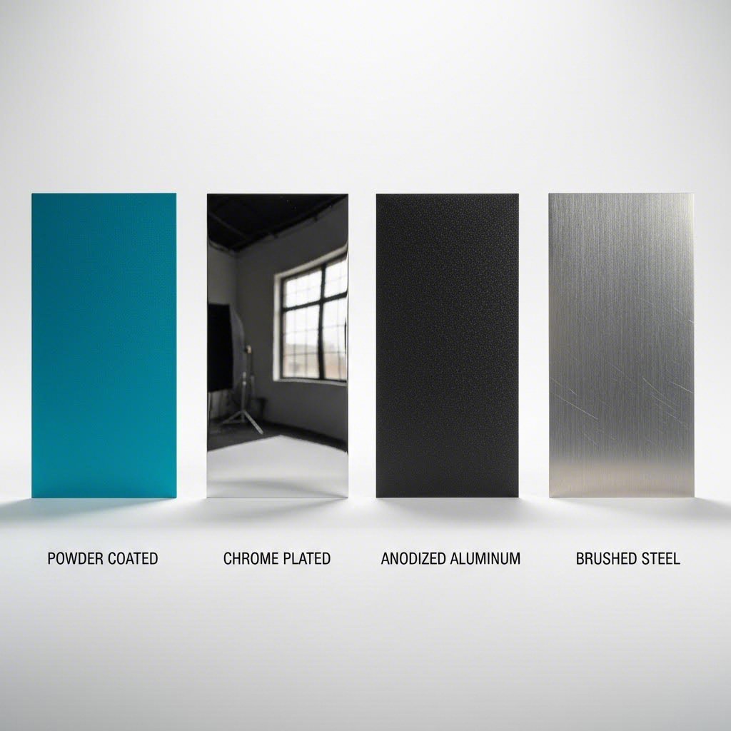
Malowanie proszkowe
Malowanie proszkowe polega na naniesieniu suchego proszku termoplastycznego metodą elektrostatyczną, a następnie wypaleniu go pod wpływem ciepła, tworząc trwałe i jednolite wykończenie. Ten proces tworzy twardą powłokę, która jest bardziej trwała niż farba natryskowa, co czyni ją standardowym wyborem dla komponentów wymagających zarówno ochrony, jak i estetyki.
- Główne korzyści: Doskonała odporność na korozję i ścieranie; jednolite pokrycie, w tym krawędzie i narożniki; szeroki wybór kolorów; przyjazne dla środowiska ze względu na minimalne emisje lotnych związków organicznych (VOC)
- Typowa grubość: 0,002" do 0,006" (50–150 mikronów)
- Najlepsze zastosowania: Obudowy urządzeń zewnętrznego użytku, elementy architektoniczne, obudowy urządzeń gospodarstwa domowego, akcesoria samochodowe, ramy mebli
- Rozważania: Wymaga podłoża przewodzącego elektrycznie; temperatury utwardzania (350–400°F) mogą wpływać na elementy wrażliwe na ciepło; grubość może wpływać na zespoły wymagające ścisłych tolerancji
Galwanizacja (cynk, nikiel, chrom)
Powlekanie elektrolityczne nanosi cienkie warstwy metalu na części za pomocą procesów elektrochemicznych. Różne metale powlekane pełnią różne funkcje – cynk chroni przed korozją, nikiel zapewnia odporność na zużycie i estetyczny wygląd, chrom daje twardość oraz wykończenie dekoracyjne.
- Zalety cynkowania: Tani sposób ochrony przed korozją; powłoka ofiarna chroni metal bazowy nawet przy uszkodzeniu; różne opcje konwersji chromatowej dla zwiększonej ochrony
- Zalety niklowania: Doskonała odporność na zużycie; jasny, dekoracyjny wygląd; dobra zdatność do lutowania w zastosowaniach elektronicznych
- Zalety chromowania: Nadzwyczajna twardość i odporność na zużycie; wysoce odbijające światło wykończenie dekoracyjne; doskonała odporność na korozję
- Najlepsze zastosowania: Wkręty, listwy samochodowe, złącza elektroniczne, sprzęt dekoracyjny, powierzchnie pracujące
Anodyzowanie (aluminium)
Anodowanie tworzy grubszą i twardszą warstwę tlenkową na aluminium poprzez przemianę elektrochemiczną. Nie tylko chroni stopy aluminium przed warunkami atmosferycznymi, ale również zapewnia izolację elektryczną.
- Główne korzyści: Doskonała odporność na korozję; integralne powłokowanie nie odspaja się ani nie łuszczy; dostępne w bezbarwnych lub kolorowych wykończeniach; zwiększona twardość powierzchni
- Typowa grubość: 0,0002" do 0,001" (5–25 mikronów)
- Najlepsze zastosowania: Elementy lotnicze, obudowy elektroniczne, aluminium architektoniczne, urządzenia medyczne, elektronika użytkowa
- Rozważania: Działa wyłącznie na aluminium i tytanie; zmiany wymiarowe należy uwzględnić przy projektowaniu; dopasowanie koloru między partiami może się różnić
Pasywacja (stal nierdzewna)
Pasywacja usuwa wolny żelazo z powierzchni stali nierdzewnej i wzmocnia naturalną warstwę tlenku chromu, która zapewnia odporność na korozję. To zabieg chemiczny jest niezbędny dla elementów ze stali nierdzewnej pracujących w trudnych warunkach.
- Główne korzyści: Przywraca odporność na korozję po obróbce; usuwa zanieczyszczenia powierzchniowe po obróbce skrawaniem lub kształtowaniu; brak zmiany wymiarów; zachowuje przewodność elektryczną
- Najlepsze zastosowania: Urządzenia medyczne, sprzęt do przetwórstwa żywności, komponenty farmaceutyczne, wyposażenie okrętowe, sprzęt do przetwórstwa chemicznego
Malowanie mokre
Tradycyjna farba ciekła pozostaje opcją dla niektórych zastosowań, choć w zastosowaniach przemysłowych została w dużej mierze zastąpiona przez malowanie proszkowe. Malowanie mokre oferuje zalety w przypadku dużych elementów, dopasowania kolorów i możliwości naprawy lokalnych uszkodzeń.
- Główne korzyści: Niższe temperatury utwardzania niż przy malowaniu proszkowym; łatwiejsze dopasowanie kolorów niestandardowych; odpowiednie dla bardzo dużych elementów; możliwa naprawa w terenie
- Rozważania: Mniejsza trwałość niż przy malowaniu proszkowym; emisja lotnych związków organicznych wymaga kontroli środowiskowej; często wymagane kilka warstw dla wystarczającej ochrony
Ponad surowy metal – dobór obróbki powierzchniowej
Wybór odpowiedniego wykończenia wiąże się z równoważeniem wielu czynników. Oto jak dopasować procesy blacharskie do konkretnych wymagań:
Wymagania dotyczące odporności na korozyję
Twoje środowisko pracy decyduje o minimalnych poziomach ochrony. Zastosowania wewnątrz pomieszczeń z kontrolowanym klimatem mogą wymagać jedynie podstawowego cynkowania. Warunki zewnętrzne lub morskie wymagają powłoki proszkowej, anodowania lub specjalistycznego pokrycia odpornego na korozję. W przypadku narażenia na działanie chemikaliów konieczne jest staranne dopasowanie składu wykończenia do konkretnych czynników korozyjnych.
Wygląd i estetyka
Produkty skierowane do konsumentów wymagają estetycznie atrakcyjnych powierzchni. Powłoka proszkowa oferuje największą gamę kolorów przy jednoczesnej spójności wyglądu. Chromowanie i niklowanie zapewniają jasne, lśniące powierzchnie. Anodyzowane aluminium daje wyrafinowane metaliczne kolory, zachowując jednocześnie naturalną fakturę metalu. Rozważ, czy wykończenie matowe, satynowe czy błyszczące najlepiej odpowiada pozycjonowaniu Twojego produktu.
Właściwości elektryczne i termiczne
Powłoka konwersyjna chromianowa zachowuje przewodność elektryczną, co czyni ją niezbędną w zastosowaniach uziemiających i do osłon przed interferencjami elektromagnetycznymi (EMI). Anodowanie i powłoki proszkowe tworzą bariery izolacyjne – korzystne dla izolacji elektrycznej, ale problematyczne, gdy wymagana jest przewodność. Zaprojektuj punkty uziemienia i strefy styku przed określeniem wykończenia.
Rozważania dotyczące kosztów
Koszty wykończenia różnią się znacząco w zależności od metody i złożoności elementu. Ocynkowanie oferuje najbardziej ekonomiczną ochronę dla stali. Powłoka proszkowa zapewnia doskonałą wartość dla dużych, prostych geometrii. Anodowanie jest droższe, ale oferuje lepszą wydajność dla aluminium. Chromowanie ma najwyższą cenę, ale może być uzasadnione ze względu na odporność na zużycie lub wymagania dekoracyjne.
Kontrola jakości w wykończeniu
Jakość wykończenia bezpośrednio wpływa na działanie końcowego produktu. Kompleksowe zapewnienie jakości obejmuje wiele punktów kontrolnych:
- Kontrola wymiarowa: Sprawdź, czy grubość powłoki nie narusza krytycznych tolerancji; weryfikacja CMM dla precyzyjnych zespołów
- Kontrole jakości powierzchni: Wizualna kontrola jednolitości powłoki, efektu pomarańczowej skórki, śladów ściekania lub zanieczyszczeń; testy przyczepności zgodnie ze standardami ASTM
- Pomiar grubości powłoki: Pomiar magnetyczny lub prądami wirowymi potwierdza zgodność z wymaganiami specyfikacji
- Test chlorkiem soli: Przyspieszone testy korozyjne potwierdzają poziom ochrony w krytycznych zastosowaniach
- Certyfikacja materiału: Dokumentacja potwierdzająca skład chemiczny powłoki, materiały użyte do powłoki oraz parametry procesu
Operacje na blachach produkujące Twoje elementy są równie dobre co procesy wykańczania, które je chronią. Idealnie uformowany komponent, który ulega przedwczesnej korozji lub wygląda niewystarczająco, oznacza marnowanie inwestycji produkcyjnych. Odpowiednio dobrana wyprawka, stosowana przez wykwalifikowanych partnerów ds. wykańczania, zapewnia prawidłowe działanie Twoich części przez cały okres ich użytkowania.
Po poznaniu dostępnych opcji wykończenia ostatnim elementem układanki jest wybór partnera produkcyjnego, który będzie w stanie zrealizować pełen proces – od wstępnego projektu po gotowe, zweryfikowane pod względem jakości komponenty.
Wybór odpowiedniego partnera produkcyjnego
Zaprojektowałeś swoje elementy, wybrałeś materiały, określiłeś wykończenia i potwierdziłeś, że blacharstwo jest odpowiednim procesem. Nadchodzi teraz decyzja, która może zdecydować o sukcesie lub porażce Twojego projektu: wybór partnera, który rzeczywiście wykona Twoje komponenty. Prawidłowy partner w zakresie blacharstwa i montażu dostarcza wysokiej jakości części na czas. Zły powoduje problemy, które rozprzestrzeniają się na cały łańcuch dostaw.
Praca z blachą wymaga więcej niż tylko wyposażenie – wymaga doświadczenia, systemów jakości oraz umiejętności skutecznego współpracy na każdym etapie produkcji. Niezależnie od tego, czy wprowadzasz nowy produkt, czy optymalizujesz istniejący łańcuch dostaw, poniżej przedstawiamy sposób oceny potencjalnych partnerów produkcyjnych i usprawnienia procesu zakupowego.
Co szukać w partnerze produkcyjnym
Rozpoczynając ocenę dostawców, opieraj się nie tylko na podanych cenach. Najniższa oferta często okazuje się najdroższym wyborem, gdy pojawią się problemy z jakością, przekroczone terminy realizacji i trudności w komunikacji. Zamiast tego oceniaj potencjalnych partnerów pod wieloma kryteriami, które przewidują długoterminowy sukces.
Certyfikaty i systemy jakości
Certyfikaty informują, czy producent ma ustandaryzowane procesy zapewniania jakości – a nie tylko dobre intencje. Certyfikat ISO 9001 stanowi podstawowy standard zarządzania jakością obowiązujący we wszystkich branżach. Jednak dla zastosowań specjalistycznych będą potrzebne dodatkowe certyfikaty.
Dla montażu blach karoseryjnych w przemyśle motoryzacyjnym Certyfikat IATF 16949 jest niezbędny . Ten globalnie uznany standard jakości w branży motoryzacyjnej zapewnia, że producenci utrzymują skuteczne systemy zarządzania jakością obejmujące orientację na klienta, ciągłą poprawę oraz podejmowanie decyzji opartych na dowodach. Dostawcy certyfikowani zgodnie z IATF 16949 wykazują, że są w stanie spełnić rygorystyczne wymagania producentów OEM i dostawców poziomu 1.
Poza certyfikatami, pytaj o kontrolę statystyczną procesów, możliwości pomiarowe oraz systemy śledzenia materiałów. Te szczegóły operacyjne pokazują, czy jakość jest wpisana w codzienne działania, czy tylko wyświetlona na tablicy na ścianie.
Możliwości wyposażenia i technologia
Współczesna produkcja i wytwarzanie wymagają zaawansowanego sprzętu. Urządzenia umożliwiające precyzyjną i dokładną produkcję zmniejszą kosztowne błędy i zagwarantują otrzymanie produktów najwyższej jakości. Oceń, czy potencjalni dostawcy posiadają:
- Systemy cięcia laserowego zdolne do obróbki Twoich typów materiałów i grubości
- Giętarki CNC o wystarczającej tonażu i długości stołu dla Twoich elementów
- Pralnie tłoczące odpowiednie do wielkości Twojej produkcji
- Możliwości spawania odpowiadające wymaganiom dotyczącym połączeń (MIG, TIG, spawanie punktowe)
- Wewnętrzne opcje wykańczania, które usprawniają cały proces produkcyjny
Oferowane kompleksowe zakłady produkcyjne, kontrolujące każdy etap produkcji, zapewniają znaczące korzyści. Gdy cięcie, kształtowanie, spawanie i wykańczanie odbywają się pod jednym dachem, unikasz opóźnień w dostawach części od zewnętrznych dostawców – co skraca czas realizacji zamówienia i zmniejsza złożoność koordynacji.
Szybkość i elastyczność prototypowania
Oto cecha, która odróżnia dobrych partnerów od tych najlepszych: możliwość szybkiego zweryfikowania projektu przed inwestowaniem w narzędzia produkcyjne. Możliwość wytwarzania prototypów z blach pozwala na posiadanie fizycznych elementów, sprawdzenie pasowania i funkcjonalności oraz wczesne wykrycie błędów projektowych – kiedy wprowadzanie zmian jest jeszcze tanie.
Wolny proces prototypowania oznacza, że przez tygodnie będziesz czekać na przegląd swojego prototypu, co dodatkowo wydłuża cały proces. Szukaj partnerów oferujących szybkie wykonanie prototypów – niektórzy producenci dostarczają prototypy już w ciągu 1–5 dni. Taka szybkość umożliwia szybszą iterację projektową i skraca całkowity czas wprowadzenia produktu na rynek.
W zastosowaniach motoryzacyjnych producenci tacy jak Shaoyi Metal Technology ofertę szybkiego prototypowania w ciągu 5 dni specjalnie dla podwozi, zawieszeń i elementów konstrukcyjnych. Łącznie z certyfikatem IATF 16949, ta możliwość pozwala inżynierom na szybką weryfikację projektów przy jednoczesnym zachowaniu standardów jakościowych odpowiednich dla przemysłu motoryzacyjnego.
Wsparcie techniczne i doświadczenie w DFM
Najlepsi partnerzy produkcyjni robią więcej niż tylko wykonują rysunki – pomagają je ulepszać. Doświadczone zespoły mogą dopracować projekty pod kątem łatwości produkcji i uniknąć czasochłonnych błędów w przyszłości. Wczesne sprawdzenie projektu pod kątem łatwości produkcji (DFM) pozwala zidentyfikować możliwości optymalizacji, które obniżają koszty i zapobiegają problemom w trakcie produkcji.
Gdy poznasz zasady obróbki metali, zrozumiesz, jak bardzo decyzje projektowe wpływają na trudność produkcji. Doświadczony partner dostrzeże problemy takie jak niewystarczające odgięcie przy gięciu, otwory zbyt blisko linii gięcia lub elementy wymagające drogich narzędzi specjalnych – i zaproponuje alternatywy, zanim ustalisz projekt.
Shaoyi Metal Technology oferuje kompleksowe wsparcie DFM w połączeniu z szybką odpowiedzią w ciągu 12 godzin, umożliwiając inżynierom branży motoryzacyjnej uzyskanie błyskawicznej informacji zwrotnej dotyczącej możliwości produkcji, gdy projekt jest jeszcze elastyczny. Współpraca na wczesnym etapie zapobiega kosztownym przebudowom projektu po złożeniu zamówienia na formy.
Optymalizacja Twojego łańcucha dostaw
Oprócz wyboru odpowiedniego partnera, optymalizacja procesu zakupów redukuje tarcie i przyspiesza realizację projektów. Oto jak wygląda produkcja w branży, gdy łańcuch dostaw działa sprawnie.
Pytania do zadania potencjalnym dostawcom
Zanim zaangażujesz się z partnerem produkcyjnym, uzyskaj jasne odpowiedzi na następujące kluczowe pytania:
- Jak bardzo pewien jesteś, że otrzymam swoje części dokładnie wtedy, kiedy mówisz? Pewność jest lepsza niż agresywne obietnice kończące się opóźnionymi dostawami.
- Jaki jest Twój wskaźnik dostaw na czas? Najlepsi producenci osiągają stabilnie powyżej 95% dostaw na czas.
- Czy oferujesz informacje zwrotne dotyczące możliwości produkcji (DFM) w ramach procesu wyceny?
- Jakie certyfikaty posiadasz i czy są one aktualne?
- Czy możesz pokazać przykłady podobnych części, które już wyprodukowano?
- Jaka jest Twoja zdolność produkcyjna i jak radzisz sobie ze zmianami zapotrzebowania?
- W jaki sposób przekazujesz status projektu i rozwiązujesz problemy, gdy się pojawią?
- Czy Twój dostawca bierze odpowiedzialność za swoje błędy? Odpowiedzialność stanowi podstawę zaufania w każdej relacji z dostawcą.
Wartość szybkiego udzielenia oferty
Szybkość na etapie wyceny ma większe znaczenie, niż wielu zakupowych sobie uświadamia. Gdy oceniasz opcje projektowe lub odpowiadasz na zapytania swoich klientów, oczekiwanie kilka dni na oferty spowalnia podejmowanie decyzji. Partnerzy oferujący szybkie udzielenie ofert — niektórzy w ciągu zaledwie 12 godzin — pozwalają utrzymać ciągłość Twoich projektów.
Szybkie oferty są również sygnałem wydajności operacyjnej. Producent, który potrafi dokładnie wycenić Twoje elementy w ciągu kilku godzin, najprawdopodobniej dysponuje dobrze zorganizowanymi systemami, doświadczonymi kalkulatorami oraz przejrzystym obrazem swojej dostępnej mocy i kosztów.
Budowanie długoterminowych partnerstw
Prawdziwe partnerstwo wymaga zarówno zaufania, jak i gotowości do podejmowania ryzyka . Najlepsze relacje z dostawcami wykraczają poza czysto transakcyjne zakupy i przekształcają się w rzetelną współpracę. Gdy Twój partner produkcyjny rozumie Twój biznes, przewiduje Twoje potrzeby i proaktywnie sugeruje usprawnienia, oznacza to, że znalazłeś coś naprawdę wartościowego.
Szukaj partnerów, którzy są gotowi inwestować w Twoje sukcesy – takich, którzy modernizują swoje wyposażenie, szkolą swoje zespoły i stale doskonalą swoje procesy. Dostawcy, którzy utrzymują się na czołowych pozycjach i nadal wierni są swoim wartościom, stają się przewagą konkurencyjną, a nie tylko dostawcami.
Nie ważne, czy zakupujesz komponenty podwozia samochodowego, obudowy elektroniczne, czy osłony urządzeń przemysłowych, zasady pozostają te same: zweryfikuj możliwości, potwierdź systemy jakości oraz preferuj partnerów, którzy oferują doświadczenie inżynierskie równolegle z możliwościami produkcyjnymi. Czas poświęcony na wybór odpowiedniego partnera produkcyjnego przekłada się na korzyści w całym cyklu życia produktu – jakość, niezawodność oraz ogólny koszt posiadania.
Często zadawane pytania dotyczące produkcji blach stalowych
1. Jakie są 5 operacji na blachach?
Pięć podstawowych operacji na blachach to ścinanie (cięcie prostych linii), tłoczenie zgrubne (cięcie całych kształtów), przebijanie (tworzenie otworów), gięcie (formowanie kątów i krzywych) oraz wykrojnikowanie (tworzenie trójwymiarowych kształtów z płaskich zagęszczeń). Do dodatkowych operacji należą grawerowanie, mintowanie i obcinanie. Procesy te współpracują w przepływie produkcji – operacje cięcia występują zazwyczaj najpierw, aby utworzyć płaskie zagęszczenia, po których następują operacje kształtujące, przekształcające je na funkcjonalne komponenty.
2. Jaka jest różnica między produkcją blacharską a konstrukcją blacharską?
Wytwarzanie blach polega na tworzeniu surowych blach z materiałów podstawowych poprzez operacje produkcyjne na dużą skalę, takie jak walcowanie, cięcie i wykańczanie, w celu uzyskania blach o grubości zazwyczaj od 0,5 mm do 6 mm. Technologia blacharska to kolejny proces przekształcania tak wyprodukowanych blach w niestandardowe komponenty poprzez cięcie, gięcie, spawanie i montaż dla konkretnych zastosowań. Wytwarzanie dostarcza surowy materiał, a technologia blacharska tworzy gotowe części.
3. Jak wybrać odpowiedni materiał na projekt z blachy?
Wybór materiału zależy od wymagań Twojej aplikacji. Stal oferuje doskonałą wytrzymałość i rentowność kosztów w zastosowaniach konstrukcyjnych. Aluminium zapewnia znakomity stosunek wytrzymałości do masy oraz przewodność cieplną, co czyni je idealnym dla elektroniki i przemysłu lotniczego. Stal nierdzewna charakteryzuje się odpornością na korozję, dlatego znajduje zastosowanie w przetwórstwie żywności i sprzęcie medycznym. Należy brać pod uwagę takie czynniki jak wytrzymałość mechaniczna, odporność na korozję, kształtowalność, ograniczenia związane z wagą, właściwości termiczne oraz całkowity koszt cyklu życia, a nie tylko cenę materiału za kilogram.
4. Jakie certyfikaty należy poszukiwać u partnera zajmującego się produkcją blach stalowych?
ISO 9001 to podstawowy standard zarządzania jakością dla ogólnego przemysłu produkcyjnego. W zastosowaniach motoryzacyjnych niezbędne jest certyfikowanie według IATF 16949 – ten powszechnie uznawany standard gwarantuje rygorystyczne systemy jakości obejmujące skupienie na kliencie, ciągłą poprawę oraz podejmowanie decyzji opartych na dowodach. Dla przemysłu lotniczego wymagane jest certyfikowanie AS9100, a dla wyrobów medycznych ISO 13485. Ponadto warto ocenić możliwości kontroli statystycznego sterowania procesem, systemy pomiarowe oraz praktyki umożliwiające śledzenie pochodzenia materiałów.
5. Kiedy należy wybrać blachę zamiast frezowania CNC lub druku 3D?
Wybierz blachę do cienkościennych konstrukcji, obudów, wsporników, chassis oraz elementów tłoczonych w partiach od 100 do ponad 100 000 sztuk. Obróbka CNC jest lepszym rozwiązaniem dla masowych kształtów 3D wymagających ścisłych tolerancji przy partiach poniżej 100 sztuk. Druk 3D doskonale sprawdza się w przypadku złożonych organicznych geometrii oraz prototypów w ilości 1–100 sztuk. Odlewanie staje się opłacalne powyżej 10 000 sztuk dla złożonych pełnych kształtów. Decyzja powinna uwzględniać wymagania geometryczne, wielkość produkcji, harmonogram oraz całkowity koszt.