 Małe partie, wysokie standardy. Nasza usługa szybkiego prototypowania sprawia, że weryfikacja jest szybsza i łatwiejsza —

Obrobka blach: 10 kluczowych punktów – od procesu po wybór partnera
Czym jest obróbka blach i dlaczego jest ważna
Kiedyś zastanawiałeś się, jak powstaje obudowa chroniąca Twój laptop, podwozie Twojego samochodu lub kanały wentylacyjne w Twoim domu? Odpowiedź tkwi w jednym z najbardziej uniwersalnych procesów produkcyjnych. Zrozumienie, czym jest obróbka blach, pozwala docenić sposób, w jaki tworzone są niezliczone produkty, których używamy na co dzień.
Obróbka blach to proces przekształcania płaskich arkuszy metalu w funkcjonalne części i zespoły poprzez cięcie, gięcie oraz łączenie.
Ta definicja oddaje istotę metody produkcyjnej, która od dziesięcioleci kształtuje współczesną branżę przemysłową. W przeciwieństwie do odlewania czy kucia, ta metoda zaczyna się od płaskiego arkusza metalu i wykorzystuje różne techniki, aby tworzyć trójwymiarowe komponenty bez usuwania znaczącej ilości materiału. Wynik? Lekkie, a jednocześnie wytrzymałe elementy stosowane w niemal wszystkich sektorach przemysłu.
Od blachy do gotowych części funkcjonalnych
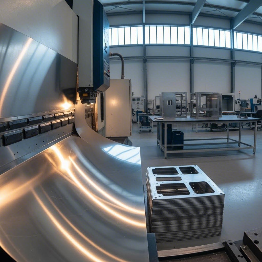
Proces przejścia od surowej blachy do gotowego komponentu obejmuje kilka starannie zaplanowanych etapów. Najpierw inżynierowie projektują detal przy użyciu oprogramowania CAD. Następnie płaską blachę poddaje się operacjom cięcia, takim jak cięcie laserowe, tłoczenie lub nożycowe, aby uzyskać podstawowy kształt. Kolejnym etapem jest formowanie, podczas którego prasy giętarskie nadają materiałowi pożądany kształt geometryczny. Na końcu metody łączenia, takie jak spawanie, nitowanie lub montaż elementów łącznych, pozwalają połączyć poszczególne detale w całościowe zespoły.
Co odróżnia produkcję blach od innych metod obróbki metalu? Kluczowa różnica polega na materiale wyjściowym. Podczas gdy toczenie CNC usuwa materiał z pełnych bloków, a odlewanie wylewa stopiony metal do form, obróbka blach zachowuje pierwotną grubość materiału przez większość procesu. To czyni ją wyjątkowo efektywną przy produkcji konstrukcji pustych, obudów i paneli.
Metoda produkcyjna stojąca za codziennymi produktami metalowymi
Rozejrzyj się dookoła, a zauważysz elementy z blach metalowych wszędzie. Zewnętrzne panele lodówki, skrzynki elektryczne, nadwozia samochodowe, szafy serwerowe komputerowe oraz kanały wentylacyjne HVAC wszystkie zaczynają jako płaski materiał, zanim wykwalifikowani wykonawcy przekształcą je w gotowe produkty.
Proces ten obejmuje niezwykle szeroki zakres materiałów, w tym:
- Stopy aluminium do lekkich zastosowań
- Niestralonowa stal do oporu na korozyję
- Stal hartowana na zimno dla opłacalnego zastosowania ogólnego
- Miedź i mosiądz ze względu na przewodność elektryczną
- Stal ocynkowana dla trwałości na zewnątrz
Dlaczego blacharstwo dominuje w nowoczesnej produkcji
Mimo rozwoju druku 3D i zaawansowanego frezowania CNC, ta tradycyjna metoda pozostaje niezbędna w wielu kluczowych branżach. Producentów samochodów polegają na niej przy wyrobie elementów szkieletonu i paneli karoseryjnych. Firmy lotnicze wykorzystują ją do lekkich elementów konstrukcyjnych. Przedsiębiorstwa elektroniczne są zależne od niej przy produkcji obudów i osłon przed zakłóceniami elektromagnetycznymi (EMI). Producenci urządzeń medycznych cenią jej precyzję w przypadku korpusów instrumentów chirurgicznych. Firmy instalacyjne nie mogłyby funkcjonować bez niej przy produkcji kanałów wentylacyjnych i jednostek obudowy.
Dlaczego ten proces nadal zachowuje swoje znaczenie? Odpowiedź sprowadza się do trzech czynników: skalowalność od pojedynczych prototypów do produkcji masowej, korzystny stosunek kosztów do wolumenu przy produkcji średnich i dużych serii oraz możliwość tworzenia wytrzymałych, a jednocześnie lekkich konstrukcji. Choć druk 3D doskonale sprawdza się przy złożonych prototypach, a obróbka frezarska CNC radzi sobie z precyzyjnymi elementami bryłowymi, to obróbka blach oferuje optymalny balans szybkości, kosztów i integralności strukturalnej dla szerokiego zakresu zastosowań.
Podstawowe procesy w produkcji z blach
Teraz, kiedy rozumiesz, co to jest wytwarzaniu blach porozmawiajmy o konkretnych operacjach, które umożliwiają ten proces. Każdy etap odgrywa wyraźną rolę w przekształcaniu płaskiego materiału na gotowe komponenty. Niezależnie od tego, czy projektujesz prosty wspornik, czy skomplikowaną obudowę, znajomość tych technik pozwala podejmować bardziej świadome decyzje dotyczące wykonalności i kosztów projektu.
Technologie cięcia kształtujące surowiec
Każdy projekt obróbki zaczyna się od cięcia. Ten etap polega na usunięciu materiału z arkusza, aby utworzyć podstawowy kontur elementu. Jednak oto czego wiele osób nie dostrzega: wybrana metoda cięcia wpływa na wszystko — od jakości krawędzi po dokładność wymiarową.
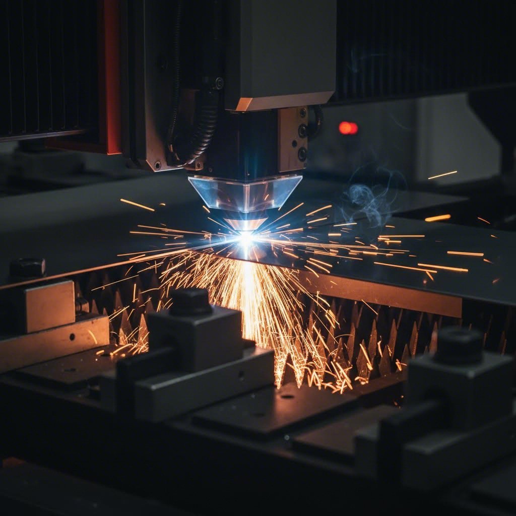
Cięcie laserowe stał się standardowym urządzeniem do precyzyjnego cięcia metalu. Skoncentrowana wiązka laserowa topi lub wyparowuje materiał wzdłuż zaprogramowanej ścieżki, tworząc czyste krawędzie przy minimalnej deformacji cieplnej. Nowoczesne lasery światłowodowe radzą sobie z materiałami od cienkiego aluminium po grube płyty stalowe, osiągając tolerancje rzędu ±0,003 cala (0,08 mm) zgodnie z Normami DIN ISO 2768 . Jednym z kluczowych czynników, które należy wziąć pod uwagę, jest szerokość cięcia (kerf), czyli grubość usuwanego materiału w procesie cięcia. Cięcie laserowe charakteryzuje się wąską szczeliną cięcia, typowo od 0,1 mm do 0,3 mm, co oznacza mniejsze straty materiału oraz gęstsze rozmieszczenie elementów na arkuszu.
Cięcie tłoczne i blankowanie wyróżnia się, gdy potrzebujesz wysokiej wydajności. Te procesy wykorzystują hartowane stalowe matryce do cięcia materiału jednym ruchem. Wyobraź sobie tłoczenie setek identycznych podkładek na minutę, a zrozumiesz, dlaczego producenci preferują przebijanie do powtarzalnych kształtów. Wada? Wymaga to początkowych nakładów na oprzyrządowanie, przez co ta metoda jest najbardziej opłacalna przy większych seriach produkcyjnych.
Plazma i cięcie strumieniem wody uzupełniają ofertę. Plazma radzi sobie z grubszymi materiałami przy niższym koszcie niż laser, podczas gdy strumień wody może przetwarzać praktycznie każdy materiał bez stref wpływu ciepła. Każda technologia znajduje swoje miejsce w zależności od typu materiału, jego grubości oraz wymagań dotyczących precyzji.
Operacje gięcia i kształtowania – wyjaśnienie
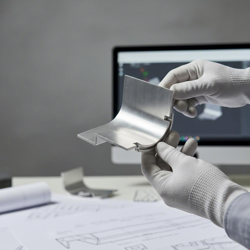
Gdy już masz wycięty płaski półprodukt, gięcie nadaje mu trójwymiarowy kształt. To właśnie tutaj kluczowa staje się wiedza w zakresie gięcia blach stalowych. Giętarki, które są podstawowym sprzętem w operacjach kształtowania, wykorzystują tłok i matrycę do tworzenia dokładnych kątów wzdłuż zaprogramowanych linii gięcia.
Oto czego projektanci często świadczą za późno: każdy materiał ma minimalny promień gięcia. Zbyt ciasne gięcie prowadzi do pękania zewnętrznej powierzchni. Zgodnie z wytycznymi branżowymi z odniesienia Xometry dotyczącego promienia gięcia, minimalny promień gięcia zwykle wynosi grubość materiału dla miękkiego aluminium, podczas gdy stal nierdzewna może wymagać promienia od 1,5 do 2 razy większego niż grubość.
Kluczowe czynniki wpływające na jakość gięcia to:
- Rodzaj materiału: Aluminium można ginać łatwiej niż stal nierdzewną
- Kierunek ziarna: Gięcie prostopadle do ziarna zmniejsza ryzyko pękania
- Grubość blachy: Grubsze blachy wymagają większych otworów matrycy V i większej siły gięcia
- Kąt gięcia: Ostrzejsze kąty wymagają bardziej precyzyjnego doboru narzędzi
Otwór V matrycy bezpośrednio wpływa na wynik. Grubsze blachy potrzebują większych otworów, aby zapobiec znakom i zapewnić odpowiedni przepływ materiału. Błędne dobrane tej relacji prowadzi do pękniętych gięć, niestabilnych kątów lub uszkodzeń powierzchni, które wymagają kosztownej poprawki.
Metody łączenia dla integralności konstrukcji
Indywidualne wyroby formowane rzadko występują samodzielnie. Metody łączenia łączą elementy w funkcjonalne zespoły. Twój wybór zależy od wymagań dotyczących wytrzymałości, oczekiwań estetycznych oraz wielkości produkcji.
Podczas porównywania spawania MIG i TIG w zastosowaniach blacharskich, każda z tych technik oferuje wyraźne zalety. Spawanie MIG (Metal Inert Gas) wykorzystuje ciągle doprowadzany elektrodę drutową, co czyni je szybsze i łatwiejsze w nauce. Jest idealne dla grubszych materiałów oraz środowisk o wysokiej produkcji, gdzie liczy się prędkość. Spawanie TIG (Tungsten Inert Gas) zapewnia lepszą kontrolę i czystsze spoiny, co czyni je preferowaną metodą dla widocznych połączeń i cienkich materiałów. Spawanie aluminium szczególnie często wymaga technik TIG ze względu na wrażliwość tego metalu na ciepło oraz trudności związane z warstwą tlenową.
Zęby oferta alternatywy dla połączeń mechanicznych bez konieczności stosowania ciepła. Wkłucia typu pop rivet działają od jednej strony elementu, idealne dla zamkniętych struktur, gdzie dostęp od tyłu jest niemożliwy. Nitowanie pełne zapewnia maksymalną wytrzymałość w zastosowaniach lotniczych i konstrukcyjnych.
Wprowadzanie elementów złącznych dodaje gwintowane elementy do połączeń śrubowych. Nakrętki PEM, wpusty i dystanse wciskane są w uprzednio przebitą dziurę, tworząc trwałe punkty mocujące bez konieczności spawania. Ta metoda zachowuje wykończenie powierzchni i dobrze sprawdza się w materiałach cienkich, które nie mogą utrzymać gwintów nacinanych.
| Rodzaj procesu | Najlepsze zastosowania | Typowe tolerancje | Zakres grubości materiału | Koszt względny |
|---|---|---|---|---|
| Cięcie laserowe | Złożone kontury, precyzyjne części, prototypy | ±0,003 cala (0,08 mm) | 0,5 mm - 25 mm | Średni |
| Kucie/Wycinanie | Proste kształty o dużej liczbie sztuk, otwory, wycięcia | ±0,005 cala (0,13 mm) | 0,5 mm - 6 mm | Niska (duża seria) |
| Gięcie na prasie falowniczej | Kołnierze, kanały, obudowy, uchwyty | ±0,5° kąt, ±0,010 cala | 0,5 mm - 12 mm | Niski do średni |
| Włókno MIG | Zespoły konstrukcyjne, grube materiały, spawanie produkcyjne | Zależne od umiejętności operatora | 1 mm i więcej | Niski do średni |
| Złóżka TIG | Cienkie materiały, widoczne spoiny, aluminium, stal nierdzewna | Możliwa wysoka precyzja | 0,5 mm i więcej | Średni do wysoki |
| Wyrzucanie | Połączenia mechaniczne, różne materiały, montaż bez ciepła | ±0,010 cala (0,25 mm) | 0,5 mm - 6 mm łącznie | Niski |
Zrozumienie tych podstawowych procesów pomaga w efektywnej komunikacji z partnerami produkcyjnymi oraz w podejmowaniu świadomych decyzji projektowych. Jednak wybór procesu to tylko część zagadnienia. Wybrany materiał zasadniczo wpływa na to, co jest możliwe, co prowadzi nas do kluczowego tematu: doboru materiału.
Przewodnik wyboru materiału dla projektów z blachy
Wybór odpowiedniego materiału może zadecydować o powodzeniu lub niepowodzeniu projektu. Opanowałeś już procesy, ale teraz nadszedł czas na decyzję, która wpływa na wszystko – od łatwości produkcji po długoterminową wydajność. Niezależnie od tego, czy budujesz lekkie obudowy, czy elementy konstrukcyjne o dużej wytrzymałości, ten przewodnik zapoznaje Cię z najważniejszymi dostępnymi opcjami.
Stopy aluminium do zastosowań krytycznych pod względem masy
Gdy oszczędność masy decyduje o projekcie, blacha aluminiowa staje się oczywistym wyborem. Mając około jednej trzeciej masy stali, stopy aluminium zapewniają imponujący stosunek wytrzymałości do wagi, oferując jednocześnie naturalną odporność na korozję. Jednak oto na czym często przegapiają inżynierowie: nie wszystkie stopy aluminium jednakowo sprawdzają się w obróbce.
Zgodnie z katalogiem materiałów Xometry najczęściej używane stopy aluminium w obróbce blach to:
- 5052:Podstawowy stop o doskonałej odporności na korozję i najwyższej wytrzymałości wśród opcji niemodyfikowanych cieplnie. Świetnie spawalny metodami MIG lub TIG, co czyni go idealnym do zastosowań morskich i zbiorników paliwa.
- 6061:Stop utwardzany wydzieleniowo zawierający magnez i krzem. Oferuje dobre właściwości mechaniczne i doskonałą spawalność, powszechnie stosowany w ramach konstrukcyjnych i komponentach samochodowych.
- 7075:Gdy potrzebujesz maksymalnej wytrzymałości, ten stop cynku i magnezu jest idealny. To jedna z najlżejszych dostępnych komercyjnie stopów o wyjątkowej odporności na zmęczenie, choć wymaga ostrożniejszego obchodzenia się podczas kształtowania.
Do zastosowań ogólnych stopy 5052 i 6061 spełniają większość wymagań. Stop 7075 warto zarezerwować do zastosowań lotniczych lub w warunkach dużego obciążenia, gdzie jego wyższa cena uzasadnia uzyskane korzyści eksploatacyjne.
Stale nierdzewne – gatunki i ich właściwości
Potrzebujesz trwałości, higieny lub charakterystycznego błyszczącego wykończenia? Blachy ze stali nierdzewnej zapewniają wszystkie trzy cechy. Zawartość chromu (co najmniej 10,5%) tworzy samoodnawiającą się warstwę tlenową, która zapewnia znacznie lepszą odporność na korozję niż stal węglowa. Wybór odpowiedniego gatunku wymaga jednak zrozumienia ich odmiennych właściwości.
nierdzewna stal 304 reprezentuje najbardziej popularny gatunek. Ten austenityczny stop chromowo-niklowy oferuje doskonałą odporność na korozję, dobrą kutełność i łatwość obróbki. Można go znaleźć wszędzie – od sprzętu kuchennego po panele architektoniczne. Zdaniem Industrial Metal Service jego uniwersalność czyni go domyślnym wyborem w przetwórstwie spożywczym i zastosowaniach medycznych, gdzie liczy się higiena.
316 ze stali nierdzewnej jest wybierany, gdy gatunek 304 nie wystarcza. Dodatek molibdenu poprawia odporność na chlorki i kwasy nieutleniające, co czyni go niezbędnym w środowiskach morskich, przemyśle chemicznym oraz w sprzęcie farmaceutycznym. Trzeba się spodziewać wyższej ceny, ale długotrwała trwałość często uzasadnia inwestycję.
Oba gatunki można łatwo spawać i kształtować bez nadmiernej skłonności do pękania, choć ich skłonność do umacniania podczas obróbki wymaga odpowiedniego narzędziowania i techniki podczas gięcia.
Wybór między stalą węglową a metalami specjalnymi
Gdy decyzje są podyktowane ograniczeniami budżetowymi, często wybiera się stal konstrukcyjną (stal niskowęglową). Jest ona przystępna cenowo, łatwo spawalna i kształtowalna bez użycia specjalistycznego sprzętu. Wadą jest jednak skłonność do korozji w przypadku braku ochronnych powłok.
Porównanie mosiądzu i brązu pojawia się często w zastosowaniach dekoracyjnych lub elektrycznych. Mosiądz (stop miedzi i cynku) doskonale nadaje się do obróbki skrawaniem, oferuje doskonałą przewodność i atrakcyjny złoty wygląd. Brąz (stop miedzi i cyny) charakteryzuje się lepszą odpornością na zużycie i korozję, szczególnie w warunkach morskich. Oba materiały są droższe, ale zapewniają unikalne właściwości estetyczne i funkcjonalne, których stal nie jest w stanie dorównać.
Blacha galwanizowana rozwiązuje problem korozji stali węglowej poprzez naniesienie powłoki cynkowej. Ta ochronna warstwa traci się jako pierwsza, chroniąc podstawową stal, co czyni materiały ocynkowane idealnym wyborem do zastosowań zewnętrznych, instalacji wentylacyjnych i urządzeń rolniczych. Powłoka minimalnie zwiększa koszt, jednocześnie znacząco wydłużając żywotność.
Zrozumienie systemu grubości blachy
Właśnie tutaj nowicjusze mogą się pogubić. Grubość metalu określa się za pomocą tabeli kalibrów, w której wyższe numery oznaczają cieńszy materiał. Zgodnie z referencyjną tabelą stalowych kalibrów Ryersona, ten kontraintuicyjny system pochodzi z brytyjskiej produkcji drutu z XIX wieku.
Istotna uwaga: pomiary kalibrowe nie są uniwersalne dla wszystkich materiałów. Grubość stali 14 kalibru wynosi około 0,0747 cala dla stali węglowej, podczas gdy stal nierdzewna 14 kalibru ma 0,0781 cala. Zawsze sprawdzaj odpowiednik dziesiętny dla swojego konkretnego materiału.
Typowe zastosowania według grubości obejmują:
- grubość stali 11 kalibru (0,1196 cala): Ciężkie wsporniki konstrukcyjne, ramy urządzeń, przemysłowe obudowy wymagające maksymalnej sztywności
- grubość stali 14 kalibru (0,0747 cala): Uniwersalne wsporniki, obudowy elektryczne, panele samochodowe, zastosowania średniej wytrzymałości
- 18–20 kalibrów: Lekkie obudowy, panele dekoracyjne, komponenty klimatyzacji i wentylacji, obudowy urządzeń elektronicznych użytkowych
| Materiał | Ocena formowania | Spawalność | Odporność na korozję | Koszt względny | Waga | Idealne zastosowania |
|---|---|---|---|---|---|---|
| Aluminium 5052 | Doskonały | Dobra (MIG/TIG) | Doskonały | Średni | Światło | Zastosowania morskie, zbiorniki paliwowe, obudowy |
| Aluminium 6061 | Dobre | Doskonały | Dobre | Średni | Światło | Ramy konstrukcyjne, przemysł motoryzacyjny |
| nierdzewna stal 304 | Dobre | Doskonały | Doskonały | Średni-Wysoki | Ciężkie | Wyposażenie do żywności, medycyna, architektura |
| 316 ze stali nierdzewnej | Dobre | Doskonały | Znakomity | Bardzo wysoki | Ciężkie | Zastosowania morskie, chemiczne, farmaceutyczne |
| Stal łagodna (1018) | Doskonały | Doskonały | Biedny | Niski | Ciężkie | Ogólne wyroby blacharskie, elementy malowane |
| Stal galwanizowana | Dobre | Średnia (wymaga przygotowania) | Dobre | Niski-średni | Ciężkie | Zewnętrzne, klimatyzacja, rolnictwo |
| Miedź | Doskonały | Dobre | Doskonały | Bardzo wysoki | Ciężkie | Elektryczne, dekoracyjne, przenoszenie ciepła |
| Mosiądz | Doskonały | Sprawiedliwe | Dobre | Wysoki | Ciężkie | Dekoracyjne, złącza elektryczne |
Wybór materiału stanowi podstawę dla wszystkiego, co następuje. Jednak nawet idealny materiał zawodzi bez odpowiedniego projektu. Następnie omówimy zasady projektowania, które zapobiegają kosztownym błędom i utrzymują Twoje koszty produkcji pod kontrolą.
Zasady projektowania redukujące koszty i wady
Wybrałeś idealny materiał i znasz podstawowe procesy. Ale właśnie na tym etapie wiele projektów idzie nieprawidłową drogą: błędne decyzje projektowe ignorujące rzeczywistości produkcyjne. Podczas pracy z blachą pozornie niewielkie niedociągnięcia mogą spowodować kosztowne prace poprawkowe, zużycie elementów lub opóźnienia w produkcji. Rozwiązaniem jest projektowanie uwzględniające możliwości produkcji (DFM) – systematyczne podejście, które dostosowuje zamierzenia projektowe do rzeczywistych możliwości narzędzi stosowanych w obróbce blachy.
Traktuj DFM jako mówienie językiem Twojego producenta. Każdy gięcie, otwór i wycięcie musi uwzględniać fizyczne ograniczenia materiału i sprzętu. Zrób to poprawnie, a obniżysz koszty oraz skrócisz czas realizacji. Zrób to źle, a problemy odkryjesz drogą, która będzie kosztowna.
Zasady promienia gięcia zapobiegające pękaniu
Wyobraź sobie, że zginasz karton zbyt gwałtownie. Zewnętrzna powierzchnia pęka i rozerwie się, prawda? Metal zachowuje się podobnie. Gdy zginasz blachę poza jej granice, zewnętrzne włókna rozciągają się poza punkt pękania, co powoduje widoczne pęknięcia lub ukryte rysy naprężeniowe, które później prowadzą do uszkodzenia.
Podstawowa zasada jest prosta: promień wewnętrznego gięcia powinien wynosić co najmniej tyle, co grubość materiału. Zgodnie z wytycznymi DFM firmy Norck, ten minimalny promień zapobiega pękaniu powierzchni w większości plastycznych materiałów. Jednakże twarde metale wymagają większych promieni. Aluminium 6061-T6, na przykład, osiąga najlepsze wyniki przy minimalnym promieniu gięcia równym czterokrotności grubości materiału.
Oto praktyczna wskazówka, która pozwala zaoszczędzić pieniądze: znormalizuj promienie gięcia w całym projekcie. Jeśli każdy zgięcie będzie miał ten sam promień, wytwórca może wykonać wszystkie operacje kształtowania przy użyciu jednej, stałej konfiguracji narzędzi. Każda wymiana narzędzia dodaje czasu i kosztów związanych z przygotowaniem produkcji.
Kierunek ziarna materiału ma również większe znaczenie, niż wielu projektantów sądzi. Arkusze metalowe tworzą strukturę ziarna podczas walcowania w hucie. Gięcie równoległe do tego ziarna znacznie zwiększa ryzyko pęknięć. Zgodnie z Przewodnikiem inżynierskim Five Flute , zawsze należy układać zgięcia prostopadle do kierunku ziarna, jeśli to możliwe, szczególnie przy użyciu metali hartowanych lub mniej plastycznych.
Strategiczne rozmieszczenie otworów dla integralności konstrukcyjnej
Czy kiedykolwiek widziałeś otwór, który rozciągnął się w owal po zgięciu? Ten powszechny defekt występuje, gdy otwory znajdują się zbyt blisko linii gięcia. Gdy prasa hydrauliczna formuje zgięcie, materiał przemieszcza się i rozciąga, deformując wszystkie pobliskie elementy.
Zasada zapobiegania jest prosta: zachowaj odstęp co najmniej 2,5 grubości materiału plus jeden promień gięcia między otworem a linią gięcia. Dla blachy o grubości 2 mm z promieniem gięcia 2 mm oznacza to, że otwory powinny zaczynać się w odległości minimum 7 mm od gięcia.
Odstępy między otworem a krawędzią podlegają podobnej logice. Przeciskanie otworów zbyt blisko krawędzi blachy powoduje wybrzuszenia i odkształcenia materiału. Standardy branżowe zalecają zachowanie odstępu co najmniej 1,5 grubości materiału między otworem a każdą krawędzią. Odstęp między otworami powinien wynosić co najmniej dwie grubości materiału, aby zapobiec pękaniu lub odkształceniom cienkiej przegrody pomiędzy nimi podczas przeciskania.
Projektując złożenia z blachy, należy wziąć pod uwagę wpływ montażu elementów na te zasady. Nakrętki i kołki PEM wymagają określonych średnic otworów oraz minimalnych odstępów od krawędzi, aby można je było prawidłowo zamontować bez uszkadzania otaczającego materiału.
Wycięcia kompensacyjne i wcięcia umożliwiające złożoną geometrię
Co się dzieje, gdy linia gięcia spotyka się z płaskim brzegiem? Bez interwencji materiał pęka w punkcie przejścia. Wycięcia kompensacyjne rozwiązują ten problem, usuwając niewielką ilość materiału w miejscach, gdzie stykają się zakrzywione i płaskie sekcje.
Według Wytyczne projektowe Consac , wycięcia kompensacyjne powinny być proporcjonalne do grubości materiału, zazwyczaj od 1 do 1,5 razy grubości pod względem szerokości. Długość wycięcia powinna wykraczać poza linię gięcia o co najmniej promień gięcia. Prostokątne wycięcia nadają się do większości zastosowań, choć zaokrąglone zmniejszają koncentrację naprężeń w elementach poddawanych obciążeniom zmęczeniowym.
W przypadku prototypowania blach, wycięcia kompensacyjne poprawiają również skuteczność pierwszego egzemplarza. Zapobiegają nieprzewidywalnemu pękaniu, które powoduje niestabilność wymiarów prototypu, pomagając szybciej zweryfikować projekty przed przejściem do narzędzi produkcyjnych.
Lista kontrolna DFM według typu procesu
Miej tę listę kontrolną pod ręką podczas przeglądu swoich projektów. Każdy punkt reprezentuje typowy przeoczenie, które powoduje trudności w produkcji.
Operacje cięcia:
- Minimalna szerokość szczeliny równa jest 1,5 grubości materiału, aby zapobiec odkształceniom spowodowanym ciepłem
- Unikaj bardzo małych otworów (średnica mniejsza niż grubość materiału) podczas przebijania
- Uwzględnij szerokość cięcia w obliczeniach wymiarów
- Stosuj standardowe rozmiary otworów, aby wykorzystać istniejące narzędzia
Operacje gięcia:
- Wewnętrzny promień gięcia równy lub większy niż grubość materiału
- Długość płata co najmniej 4-krotnie większa niż grubość materiału dla prawidłowego chwytu narzędzia
- Linie gięcia prostopadłe do kierunku ziarna, o ile to możliwe
- Jednolite promienie gięcia na całym elemencie, aby zminimalizować zmiany narzędzi
- Nacięcia kompensacyjne we wszystkich miejscach przejścia gięcia do krawędzi
Montaż i elementy mocujące:
- Wystarczająca przestrzeń dla narzędzi do łączników i kluczy
- Standardowe rozmiary łączników, aby zmniejszyć złożoność zapasów
- Funkcje samocentrujące zapobiegające błędnemu montażowi
- Minimalne odległości krawędziowe dla elementów wciskanych
Typowe błędy projektowe powodujące wzrost kosztów
Nawet doświadczeni inżynierowie wpadają w te pułapki. Wczesne ich rozpoznanie pozwala uniknąć kosztownych poprawek podczas produkcji.
Niewystarczające uchwyty na gięcie: Bez odpowiednich cięć kompensacyjnych materiał pęka w sposób nieprzewidywalny. Wynikowe części wymagają ręcznego szlifowania lub są całkowicie wycofywane. Zgodnie z danymi produkcyjnymi firmy Consac, pojedyncza pominięta czynność powoduje aż 15% odrzuceń blacharskich prac.
Ignorowanie kierunku ziarna: Części mogą przejść początkową kontrolę, ale pękać miesiące później pod wpływem naprężeń cyklicznych. Ten ukryty defekt prowadzi do roszczeń gwarancyjnych i niezadowolenia klientów, co znacznie przekracza koszty odpowiedniego projektowania.
Nakładanie się tolerancji: Określanie niepotrzebnie wąskich tolerancji dla każdego wymiaru dramatycznie zwiększa koszty. Zgodnie z standardy branżowe , tolerancje poniżej ±0,005 cala powodują wykładniczy wzrost kosztów, podczas gdy standardowe procesy umożliwiają osiągnięcie tolerancji ±0,010 do ±0,030 cala przy ekonomicznych kosztach. Stosuj wąskie tolerancje tylko tam, gdzie funkcjonalność tego wymaga.
Overkomplikowanie projektów prototypów blacharskich: Złożone geometrie, które wykorzystują granice możliwości produkcyjnych, mogą działać w przypadku pojedynczych prototypów, ale stają się koszmarne w produkcji seryjnej. Upraszczaj tam, gdzie to możliwe, a skomplikowane elementy zarezerwuj dla procesów lepiej do nich przystosowanych.
Inwestycja w odpowiednie DFM przynosi zyski przez cały cykl życia projektu. Zmiany projektowe stają się wykładniczo droższe w miarę postępu prac, od kilku groszy na etapie CAD do tysięcy podczas produkcji. Werylując wykonywalność już na etapie prototypowania blach, wykrywasz problemy wcześnie, gdy korekta niemal nic nie kosztuje.
Gdy projekt jest zoptymalizowany pod kątem produkcji, kolejne kluczowe pytanie to: jakimi rzeczywistymi tolerancjami można dysponować? Zrozumienie realistycznych oczekiwań dotyczących tolerancji zapobiega błędom specyfikacji, które powodują wzrost kosztów lub pogorszenie funkcjonalności.
Tolerancje i standardy jakości wytłumaczone
Zaprojektowałeś element możliwy do wytwarzania z odpowiedniego materiału. Ale pojawia się pytanie, które nawet doświadczonych inżynierów wprowadza w zakłopotanie: jakich tolerancji można faktycznie oczekiwać? Każdy proces obróbki blachy wprowadza pewne odchylenia, a zrozumienie tych granic pozwala uniknąć błędów w specyfikacji, które mogą prowadzić zarówno do wzrostu kosztów, jak i utraty funkcjonalności. Przyjrzyjmy się bliżej kwestii tolerancji i ustalmy punkty kontrolne jakości, które oddzielają niezawodne części od odrzuconych.
Oczekiwane tolerancje w różnych metodach produkcji
Każdy proces obróbki blachy charakteryzuje się innym poziomem dokładności. Określanie bardziej restrykcyjnych tolerancji niż te, które dany proces może osiągnąć, zmusza dostawcę do drogich operacji wtórnych lub całkowitego odrzucenia produktu. Zgodnie z referencją tolerancji firmy Komacut, zrozumienie właściwych możliwości poszczególnych procesów pozwala na opracowanie specyfikacji, które łączą precyzję z praktycznością.
Cięcie laserowe reprezentuje złoty standard precyzyjnej obróbki blach cienkolistnych. Standardowe tolerancje wynoszą ±0,45 mm dla wymiarów liniowych i ±0,12 mm dla średnic otworów. Potrzebujesz większej dokładności? Operacje wysokoprecyzyjne osiągają ±0,20 mm liniowo i ±0,08 mm dla otworów. Te możliwości zależą od grubości materiału – cieńsze blachy zazwyczaj charakteryzują się mniejszymi tolerancjami.
Cięcie tłoczne i blankowanie zapewniają spójne wyniki w produkcji seryjnej. Dokładność wymiarowa zazwyczaj mieści się w granicach ±0,13 mm (0,005 cala) przy prawidłowo utrzymanym narzędziowaniu. Jednak zużycie narzędzi stopniowo pogarsza tę precyzję, dlatego regularna kontrola krytycznych wymiarów jest niezbędna.
Operacje gięcia prowadzi do większej zmienności niż cięcie. Standardowe tolerancje kątowe wynoszą ±1,0°, przy czym możliwe jest osiągnięcie ±0,5° za pomocą giętarek CNC z pomiarem w trakcie procesu. Wymiary liniowe po gięciu zachowują tolerancję ±0,45 mm w warunkach standardowych, a przy pracy precyzyjnej ulegają zawężeniu do ±0,20 mm.
Oto na co często zapominają specyfikacje: narastanie tolerancji skumulowanych . Gdy łączą się wiele operacji, błędy się kumulują. Część wymagająca trzech gięć może mieć trzykrotnie większą tolerancję gięcia niż pojedyncze gięcie. Współpraca z doświadczonym wykonawcą precyzyjnej blacharstwa, który zna strategie kompensacji, znacząco wpływa na dokładność końcowej części.
| Proces | Tolerancja standardowa | Wysoka precyzja tolerancji | Główne zmienne |
|---|---|---|---|
| Cięcie laserowe (liniowe) | ±0,45 mm | ±0,20 mm | Grubość materiału, ostrość wiązki |
| Cięcie laserowe (otwory) | ±0,12mm | ±0,08 mm | Średnica otworu, rodzaj materiału |
| Kucie/Wycinanie | ±0,13 mm | ±0,08 mm | Stan narzędzi, twardość materiału |
| Gięcie (kątowe) | ±1.0° | ±0.5° | Odrost sprężysty materiału, wybór narzędzi |
| Gięcie (liniowe) | ±0,25 mm | ±0,20 mm | Kolejność gięcia, spójność materiału |
| Spawanie (odkształcenie) | ±0,5 mm - 2 mm | ±0,25 mm | Wpływ ciepła, projektacja uchwytów |
Standardy i specyfikacje wykończenia powierzchni
Tolerancje dotyczą wymiarów, ale co z wyglądem? Oczekiwania dotyczące wykończenia powierzchni różnią się znacząco w zależności od zastosowania. Wspornik konstrukcyjny ukryty wewnątrz urządzenia znacznie różni się od obudowy urządzenia medycznego widocznej dla pacjentów.
Tolerancje płaskości określają dopuszczalne odchylenie od idealnie płaskiej powierzchni. Zgodnie z wytycznymi branżowymi osiągnięcie ciasnych tolerancji płaskości jest trudne, ponieważ odkształcenia powstają na skutek wewnętrznych naprężeń materiału, metod przetwarzania oraz sposobu manipulacji podczas produkcji. Cienkie blachy bardziej łatwo uginają się podczas cięcia i gięcia, podczas gdy grubsze blachy mogą zachować pozostałe naprężenia z procesu walcowania.
Proces blacharski bezpośrednio wpływa na jakość powierzchni. Cięcie laserowe pozostawia czyste krawędzie z minimalnym zadziorami, podczas gdy tłoczenie może powodować niewielkie zadziory wymagające dodatkowego usunięcia. Gięcie może pozostawiać ślady narzędzi na powierzchniach styku, chyba że stosuje się folie ochronne lub specjalistyczne narzędzia.
Podczas określania wykończenia powierzchni należy wziąć pod uwagę:
- Powierzchnie krytyczne: Określ, które powierzchnie są istotne dla funkcji lub wyglądu
- Dopuszczalne ślady: Zdefiniuj, czy dopuszczalne są śladów narzędzi, lekkie rysy lub ślady obsługi
- Przetwarzanie końcowe: Określ, czy szlifowanie, polerowanie lub powlekanie będą naprawiać niedoskonałości powierzchni
Kontrolne punkty jakości od projektu do dostawy
Kontrola jakości w precyzyjnej obróbce blach nie jest tylko końcową inspekcją. Jest to proces systematyczny obejmujący cały cykl – od przeglądu projektu po wysyłkę. Zgodnie z Ramową strategią jakościową HiTech Digital , skuteczna kontrola jakości rozpoczyna się jeszcze przed przystąpieniem do cięcia metalu.
Weryfikacja projektu wykrywa błędy specyfikacji, zanim staną się kosztownymi problemami produkcyjnymi. Twój wytwórca powinien sprawdzić rysunki pod kątem dokładności wymiarów, realizowalności tolerancji oraz zgodności z zasadami projektowania ułatwiającego produkcję (DFM). Ten wstępny wkład zapobiega narastającym kosztom zmian w trakcie produkcji.
Certyfikacja Materiałów potwierdza, że dostarczane surowce spełniają określone parametry. Wymagaj protokołów badań huty, które dokumentują skład chemiczny, właściwości mechaniczne oraz wartości wytrzymałości na rozciąganie. W przypadku zastosowań krytycznych niezależne badania wytrzymałości na rozciąganie potwierdzają, że materiały działają zgodnie z założeniami. Ta dokumentacja zapewnia śledzenie, które jest niezbędne w zastosowaniach lotniczych, medycznych i motoryzacyjnych.
Inspekcja w trakcie procesu wykrywa odchylenia, zanim rozprzestrzenią się na całą serię produkcyjną. Kontrola pierwszego egzemplarza potwierdza, że początkowe części spełniają specyfikacje przed rozpoczęciem pełnej produkcji. Statystyczna kontrola procesu monitoruje kluczowe wymiary w trakcie całej serii, wykrywając dryft przed przekroczeniem dopuszczalnych tolerancji.
Końcowa Inspekcja weryfikuje ukończone elementy pod kątem zgodności z kryteriami akceptacji. Pomiar wymiarów, kontrola wizualna oraz sprawdzenia funkcjonalne potwierdzają, że elementy będą działać zgodnie z przeznaczeniem. W przypadku konstrukcji spawanych, nieniszczące metody badań mogą służyć weryfikacji szczelności połączeń.
Dokumentacja do żądania od partnerów wykonujących obróbkę blach
Odpowiednia dokumentacja chroni przed uchybieniami jakościowymi i zapewnia dowód zgodności w branżach objętych regulacjami. Oceniając techniki oraz partnerów związanych z gięciem blach, należy zażądać:
- Certyfikaty Materiałowe: Protokoły badań huty pokazujące właściwości chemiczne i mechaniczne
- Raporty z inspekcji pierwszego sztucznika: Udokumentowane potwierdzenie zgodności początkowych partii produkcyjnych
- Dane z kontroli wymiarowej: Wyniki pomiarów krytycznych wymiarów
- Certyfikaty procesu: Kwalifikacje spawaczy, dokumentacja obróbki cieplnej – tam gdzie ma to zastosowanie
- Rekordy śledzenia: Śledzenie partii łączące gotowe elementy ze źródłami surowców
Certyfikaty branżowe zapewniają dodatkową pewność. ISO 9001 potwierdza zgodność systemu zarządzania jakością. IATF 16949 obejmuje wymagania specyficzne dla przemysłu motoryzacyjnego. ISO 13485 dotyczy produkcji wyrobów medycznych. Te certyfikaty wymagają udokumentowanych procedur, regularnych audytów oraz ciągłej poprawy, co zmniejsza zmienność w procesie gięcia blach.
Po ustaleniu tolerancji i zdefiniowaniu punktów kontroli jakości pozostaje ważne pytanie: kiedy zastosowanie blachy jest uzasadnione w porównaniu z innymi metodami wytwarzania? Odpowiedź wiąże się z kompromisami zależnymi od konkretnych wymagań aplikacji.
Blacha stalowa a inne metody wytwarzania
Masz gotowy projekt części. Ale zanim przejdziesz do produkcji ze blachy, pojawia się kluczowe pytanie: czy to naprawdę najodpowiedniejsza metoda wytwarzania dla Twojego zastosowania? Czasem odpowiedź brzmi tak. Inne razy lepsze rezultaty dają frezowanie CNC, druk 3D lub odlewanie. Zrozumienie tych kompromisów pozwala uniknąć kosztownych błędów wyboru metody i pomaga w pełni wykorzystać zalety każdej technologii.
Punkty decyzyjne: Blacha vs. Frezowanie CNC
Kiedy giąć i formować, a kiedy obrabiać z materiału pełnego? Decyzja często zależy od geometrii, wielkości partii i efektywności zużycia materiału.
Złożoność geometrii: Frezowanie CNC radzi sobie niemal z każdym kształtem, jaki może sobie wyobrazić projektant, w tym głębokie kieszenie, podcięcia i skomplikowane trójwymiarowe krzywe. Technologia blacharska doskonale sprawdza się w przypadku konstrukcji pustych w środku, obudów oraz elementów opartych na gięciu i płaskich schematach rozwinięcia. Według Badania porównawczego firmy IMS Manufacturing , projektowanie konstrukcji blacharskich od samego początku często prowadzi do prostszych, bardziej opłacalnych obudów, które są łatwiejsze w montażu i serwisowaniu.
Efektywność materiału: W tym miejscu blachownictwo wygrywa zdecydowanie. Wytwarzanie przez obróbkę skrawaniem rozpoczyna się od pełnych brykietów, a materiał jest usuwany, aż pozostanie wyłącznie Twoja część. Cały ten usunięty materiał staje się wiórami i odpadami. Blachownictwo zachowuje pierwotną grubość materiału, tworząc lekkie konstrukcje przy minimalnych odpadach.
Progi cenowe: Dla partii prototypowych 1–10 sztuk koszty obróbki CNC mogą być konkurencyjne, ponieważ nie wymagają one inwestycji w oprzyrządowanie. Jednak wraz ze wzrostem nakładów ekonomia zmienia się diametralnie. Zgodnie z danymi branżowymi, przy nakładach powyżej 50 sztuk produkcja z blachy kosztuje niemal zawsze mniej na sztukę. Dlaczego? Operacje cięcia i gięcia trwają kilka minut na sztukę, podczas gdy skomplikowana obróbka może wymagać godzin pracy maszyny.
Uważania dotyczące wagi: Blachy tworzą lekkie obudowy z cienkiego materiału, typowo o grubości od 0,040" do 0,125". Ma to znaczenie dla urządzeń przenośnych, zmniejsza koszty przesyłki i minimalizuje wagę w zastosowaniach, gdzie każdy gram ma znaczenie. Części wykonywane metodą frezowania CNC są cięższe nawet po usunięciu materiału, chyba że zostanie przeznaczony znaczny czas na wytworzenie cienkościennych struktur.
Kiedy druk 3D jest bardziej sensowny
Metalowy druk 3D zdobywa nagłówki, ale jak sprawdza się w rzeczywistej produkcji? Odpowiedź zależy przede wszystkim od wielkości serii, stopnia skomplikowania oraz wymagań czasowych.
Szybkość prototypowania: W przypadku prototypów funkcjonalnych wymagających złożonych geometrii wewnętrznych, druk 3D zapewnia realizację w ciągu 1-2 tygodni, w porównaniu do 3-6 tygodni potrzebnych na przygotowanie form blacharskich. Zgodnie z analizą Met3DP z 2025 roku, ta przewaga pod względem szybkości czyni produkcję addytywną atrakcyjną dla weryfikacji projektów, szczególnie podczas tworzenia niestandardowych metalowych elementów ze skomplikowanymi detalami, których nie da się uformować z płaskiego materiału.
Wolność projektu: druk 3D tworzy części warstwa po warstwie, umożliwiając kanały wewnętrzne, struktury kratowe i organiczne kształty, których blacha nie jest w stanie osiągnąć. Studium przypadku Boeinga wykazało, że zastosowanie druku 3D do produkcji części zmniejszyło potrzebę montażu o nawet 40%, poprzez scalenie wielu komponentów blacharskich w pojedyncze drukowane struktury.
Optymalizacja masy: Dzięki oprogramowaniu do optymalizacji topologii, części drukowane w 3D osiągają puste struktury kratowe, które zmniejszają zużycie materiału o 50%. W zastosowaniach lotniczych, drukowane ramiona zawieszenia pozwoliły zaoszczędzić 2,5 kg na każde urządzenie, zachowując integralność konstrukcyjną.
Jednak druk 3D ma znaczące ograniczenia:
- Koszt jednostkowy: Druk metalu w 3D to koszt od 100 do 500 USD za sztukę w porównaniu do 50–200 USD za odpowiedniki z blachy
- Wykończenie powierzchni: Drukowane części wymagają obróbki końcowej w celu uzyskania gładkich powierzchni
- Skalowalność produkcji: To, co działa dla 10 prototypów, staje się ekonomicznie niewykonalne przy produkcji 500 sztuk
Punkt optymalny? Użyj druku 3D do szybkiego tworzenia prototypów podobnych do blachy metalowej podczas iteracji projektowych, a następnie przejdź do tradycyjnej produkcji dla większych serii. To podejście hybrydowe wykorzystuje szybkość wytwarzania addytywnego, jednocześnie czerpiąc korzyści z opłacalności obróbki blachy na dużą skalę.
Próg ilościowy sprzyjający różnym metodą
Każda metoda wytwarzania ma zakres ilościowy, w którym się sprawdza. Zrozumienie tych progów pozwala uniknąć płacenia cen za pracę laserem dla dużych partii, które lepiej wykonać na maszynie tłoczarskiej, i odwrotnie.
Odlewanie na maty wymaga znacznych początkowych nakładów na oprzyrządowanie, zazwyczaj 5000–50 000 USD na stworzenie formy. Ma to sens tylko wtedy, gdy produkujesz tysiące identycznych części. Poniżej tych ilości amortyzacja kosztów form na pojedynczą sztukę czyni odlewanie matrycowe zbyt drogim. Powyżej 5000–10 000 sztuk sytuacja się zmienia, a odlewanie matrycowe zapewnia niższe koszty jednostkowe niż blacha dla skomplikowanych geometrii.
Wtryskowanie materiałów staje przed podobnymi wyzwaniami dotyczącymi wielkości produkcji, ale odpowiada na inne potrzeby materiałowe. Gdy aplikacja pozwala na użycie tworzywa sztucznego, formowanie wtryskowe staje się opłacalne powyżej około 1000 sztuk. W przypadku wymagań metalowych, blacharstwo obsługuje ten sam zakres wielkości produkcji bez konieczności dużych inwestycji w narzędzia.
Zaleta prototypowania z blach staje się oczywista podczas iteracji projektowych. Zgodnie z badaniami branżowymi, produkcja blacharska płynnie skaluje się od pojedynczych prototypów aż po serie produkcyjne. Ten sam proces, który wytwarza 10 sztuk, działa również dla 1000 sztuk przy jedynie niewielkich zmianach w przygotowaniu. Eliminuje to kosztowne modyfikacje konstrukcji, często wymagane podczas przejścia z prototypów frezowanych na metody produkcji seryjnej.
| Metoda produkcji | Optymalny zakres wielkości produkcji | Krzywa kosztu jednostkowego | Czas Oczekiwania | Opcje materiałowe | Elastyczność projektowania |
|---|---|---|---|---|---|
| Wytwarzaniu blach | 10 - 10 000+ sztuk | Umiarkowany, dobra skalowalność | 1-3 tygodnie | Stal, aluminium, stal nierdzewna, miedź | Dobry dla geometrii opartych na gięciu |
| Obróbka CNC | 1 - 100 sztuk | Wysoki, słaba skalowalność | 1-4 tygodnie | Prawie każdy metal nadający się do obróbki skrawaniem | Doskonały do złożonych kształtów 3D |
| Druk 3D metalowy | 1 - 50 sztuk | Bardzo wysoki, minimalna korzyść ze skalowania | 1-2 tygodnie | Tytan, Inconel, stal nierdzewna, aluminium | Najlepszy do elementów wewnętrznych |
| Odlewanie na maty | 5 000+ jednostek | Niski po amortyzacji formy | 8-12 tygodni (forma) | Stopy aluminium, cynku, magnezu | Dobry dla złożonych kształtów |
| Formowanie wtryskowe (Metal) | 1000+ sztuk | Niski po amortyzacji formy | 6–10 tygodni (przygotowanie narzędzi) | Proszki stalowe, ze stali nierdzewnej, tytanowe | Doskonałe do małych, złożonych elementów |
Hybrydowe podejścia łączące zalety
Najbardziej roztropni producenci nie traktują tych metod jako konkurencyjnych. Łączą je strategicznie. Rozważ te sprawdzone podejścia hybrydowe:
Szybkie prototypowanie blacharskie z przejściem do produkcji: Zacznij od prototypów wykonanych CNC lub drukowanych 3D w celu wstępnego sprawdzenia projektu. Gdy projekt się ustabilizuje, przejdź do produkcji blacharskiej. To podejście pozwala szybko zweryfikować geometrię, zachowując opłacalność skalowania.
Odlewy z dodatkami z blachy: Wykorzystaj odlewanie matrycowe do skomplikowanych obudów wymagających dużych serii, a następnie dodaj uchwyty, osłony i elementy montażowe z blachy. Wykorzystuje się w ten sposób korzyści ekonomiczne odlewania dla konstrukcji nośnej, jednocześnie stosując elastyczność blachy do personalizacji.
Elementy obrabiane na częściach spawanych: Wykonaj podstawową konstrukcję z blachy, a następnie dodaj precyzyjnie obrobione powierzchnie montażowe lub gwintowane tam, gdzie wymagane są ścisłe tolerancje. To połączenie wydajności blachy z precyzją obróbki skrawaniem dokładnie tam, gdzie jest potrzebna.
Kluczowe spostrzeżenie? Dostosuj każdą część projektu do metody produkcji, która najlepiej się do niej nadaje. Podejście hybrydowe często daje lepsze wyniki niż narzucanie całego projektu jednemu procesowi.
Teraz, gdy już wiesz, gdzie pasuje blacharstwo w krajobrazie produkcji, przyjrzymy się, jak konkretne branże wykorzystują te możliwości, aby spełnić swoje specyficzne wymagania.
Zastosowania przemysłowe i specjalistyczne wymagania
Zrozumienie metod produkcji i opcji materiałowych jest wartościowe, ale oto co naprawdę liczy się: jak te możliwości przekładają się na zastosowania w świecie rzeczywistym? Każda branża stawia unikalne wymagania, które kształtują wybór materiałów, specyfikacje tolerancji oraz wymagania dotyczące wykończenia. Niezależnie od tego, czy zakupujesz komponenty nadwozia samochodowego, czy obudowy urządzeń medycznych, zrozumienie tych specyficznych dla branży wymagań pozwala skutecznie komunikować się z firmami zajmującymi się obróbką blachy i zapewnia, że Twoje części spełnią obowiązujące normy.
Wymagania i standardy blachy samochodowej
Sektor motoryzacyjny stanowi jedno z największych na świecie zapotrzebowanie na usługi obróbki stali. Od konstrukcyjnych elementów szkieletonu po dekoracyjne listwy, pojazdy w dużym stopniu polegają na kształtowanych metalowych częściach, które muszą wytrzymać trudne warunki eksploatacji i spełniać rygorystyczne wymagania bezpieczeństwa.
Typowe zastosowania w motoryzacji obejmują:
- Elementy podwozia: Elementy konstrukcyjne, poprzeczki i panele wzmocniające, które tworzą szkielet pojazdu
- Panele nadwozia: Drzwi, maski, nadkola i fragmenty dachu wymagające precyzyjnego dopasowania i wykończenia
- Zawieszenia: Elementy nośne, które muszą wytrzymywać cykliczne obciążenia bez awarii zmęczeniowych
- Osłony cieplne: Panele ochronne, które odprowadzają ciepło spalinowe od wrażliwych komponentów
- Uchwyty montażowe: Punkty mocowania silników, skrzyń biegów i systemów pomocniczych
Co odróżnia branżę motoryzacyjną od innych sektorów? Wymagania dotyczące certyfikacji. Zgodnie z przewodnikiem certyfikacji Xometry, IATF 16949 to standard systemu zarządzania jakością specjalnie zaprojektowany dla produkcji motoryzacyjnej. Ten system, oparty na fundamentach ISO 9001, koncentruje się na zapobieganiu wadom, redukcji zmienności oraz eliminowaniu marnotrawstwa w całym łańcuchu dostaw
Certyfikat IATF 16949 nie jest wymagany zgodnie z prawem, ale oto rzeczywistość praktyczna: większość producentów OEM i dostawców z pierwszego szczebla w branży motoryzacyjnej nie będzie współpracować z podmiotami nieposiadającymi certyfikatu. Certyfikat ten wykazuje zdolność firmy oraz jej zaangażowanie w ograniczanie wad przy jednoczesnym utrzymaniu spójnej jakości w całych seriach produkcyjnych. Usługi przemysłowej obróbki metali skierowane na sektor motoryzacyjny muszą zainwestować w dokumentację, kontrolę procesów oraz procedury audytowe wymagane przez ten certyfikat.
Preferowane materiały w przemyśle motoryzacyjnym to stale niskostopowe o wysokiej wytrzymałości do elementów konstrukcyjnych, stopy aluminium w celu zmniejszenia masy blach karoseryjnych oraz stal ocynkowana do obszarów narażonych na korozję. Wymagania dotyczące tolerancji są zwykle ścisłe i wynoszą ±0,25 mm dla krytycznych punktów montażowych wpływających na geometrię pojazdu i systemy bezpieczeństwa.
Uwagi dotyczące projektowania obudów elektronicznych
Producenci urządzeń elektronicznych polegają na niestandardowych metalowych obudowach, które robią znacznie więcej niż tylko zawierają komponenty. Te obudowy muszą odprowadzać ciepło, chronić przed zakłóceniami elektromagnetycznymi oraz zapewniać bezpieczne mocowanie płytek drukowanych i złącz.
Zgodnie z przewodnikiem Approved Sheet Metal dotyczącym ekranowania EMI, ochrona przed zakłóceniami elektromagnetycznymi i częstotliwością radiową wymaga starannego doboru materiałów. Bez odpowiedniego ekranowania urządzenia elektroniczne mogą charakteryzować się gorszą wydajnością, błędami w działaniu lub całkowitym uszkodzeniem.
Kluczowe aspekty obudów elektronicznych to:
- Efektywność ekranowania EMI: Przewodność materiału bezpośrednio wpływa na skuteczność ekranowania; miedź oferuje doskonałą ochronę nawet w zakresie częstotliwości GHz
- Zarządzanie cieplne: Wysoka przewodność cieplna aluminium pomaga rozpraszать ciepło z elektroniki o dużej gęstości mocy
- Ograniczenia związane z wagą: Przenośne urządzenia wymagają lekkich konstrukcji aluminiowych przy jednoczesnym zachowaniu integralności strukturalnej
- Projekt wentylacji: Strategiczne wzory perforacji zapewniają równowagę między przepływem powietrza a skutecznością ekranowania
- Wyступy pod złącza: Dokładne otwory na przewody, wyświetlacze i porty interfejsowe
Wybór materiałów na osłony EMI/RFI wiąże się z kompromisami między wydajnością a łatwością produkcji. Miedź zapewnia doskonałą przewodność, ale utlenia się bez ochronnych powłok. Aluminium oferuje bardzo dobrą ochronę z przewagą odporności na korozję i formowalności przy umiarkowanych kosztach. Stal ocynkowana cyną zapewnia dobrą ochronę z doskonałą odpornością na korozję. W zastosowaniach wymagających ochrony przed niskoczęstotliwościowym zakłóceniem magnetycznym, konieczne stają się specjalistyczne materiały takie jak stop mu, mimo ich wyższych kosztów i trudności w formowaniu.
Wytwarzanie obudów elektronicznych ze stali nierdzewnej służy zastosowaniom wymagającym trwałości i odporności na korozję, choć jej niższa przewodność w porównaniu do miedzi lub aluminium ogranicza skuteczność osłony EMI. Gdy stal nierdzewna jest wymagana ze względów środowiskowych, mogą być konieczne dodatkowe warstwy osłon lub powłoki przewodzące.
Specyfikacje produkcji urządzeń medycznych
Branża urządzeń medycznych wymaga najwyższej precyzji i standardów czystości. Zgodnie z przeglądem branży medycznej firmy Approved Sheet Metal, przedsiębiorstwa produkujące urządzenia medyczne z listy Fortune 500 powierzają specjalistycznym podwykonawcom produkcję komponentów, od obudów instrumentów chirurgicznych po ramy urządzeń diagnostycznych.
Typowe zastosowania w urządzeniach medycznych to:
- Obudowy urządzeń: Obudowy dla maszyn diagnostycznych, monitorów i urządzeń terapeutycznych
- Tace na instrumenty chirurgiczne: Pojemniki nadające się do sterylizacji służące do organizowania i transportu narzędzi
- Niestandardowe ramy rurowe: Wózki transportowe, podwozia i szafy stosowane w środowiskach medycznych
- Uchwyty komponentów: Systemy montażowe do czujników, wyświetlaczy i interfejsów sterujących
Wybór materiału do zastosowań medycznych koncentruje się na dwóch głównych opcjach. Stal nierdzewna 316 dominuje ze względu na wyjątkową odporność na korozję oraz możliwość wytrzymywania wysokich temperatur i agresywnych chemikaliów stosowanych w procesach sterylizacji. Jej polerowana powierzchnia spełnia wymagania dotyczące sterylności, kluczowe w zastosowaniach związanych z kontaktami z pacjentem. Aluminium 5052, choć nie jest najmocniejszym dostępnym stopem, znajduje zastosowanie tam, gdzie wymagane są doskonała spawalność, kształtowalność i odporność na rdzę, a waga lub koszt stali nierdzewnej są nieakceptowalne.
Wykończenie powierzchni jest równie ważne jak wybór podstawowego materiału. Branża medyczna polega na określonych technikach:
- Pasywacja: Zwiększa odporność na korozję poprzez usuwanie swobodnego żelaza z powierzchni stalowych
- Elektropolerowanie: Tworzy gładkie, lustrzane powierzchnie odporne na przyleganie bakterii
- Anodyzowanie: Zwiększa odporność na zużycie i umożliwia identyfikację wizualną poprzez kodowanie kolorowe
- Powłoka proszkowa: Dodaje ochronne, trwałe i estetyczne wykończenia
- Piaskowanie kulkowe: Tworzy jednolite, matowe, nierefleksyjne powierzchnie
Certyfikat ISO 13485 stanowi ramy zarządzania jakością w produkcji wyrobów medycznych. Ta norma obejmuje zarządzanie ryzykiem, kontrolę projektowania oraz wymagania dotyczące śledzenia produktów w zastosowaniach medycznych. Dostawcy działający w tej branży muszą prowadzić rygorystyczną dokumentację łączącą gotowe elementy ze źródłami surowców.
Wymagania lotnicze i HVAC
Zastosowania lotnicze sprawiają, że obróbka aluminium osiąga swoje granice. Oszczędność masy decyduje o każdej decyzji projektowej, a inżynierowie określają najniższe możliwe grubości materiału, zachowując jednocześnie integralność konstrukcyjną w ekstremalnych warunkach. Wymagania dokładności często przekraczają standardowe możliwości produkcyjne, wymagając specjalistycznego sprzętu i protokołów inspekcji.
Kluczowe aspekty branży lotniczej to:
- Śledzenie materiałów: Kompletna dokumentacja od surowca po gotowy komponent
- Precyzja wymiarowa: Tolerancje ograniczone do ±0,05 mm dla krytycznych zespołów
- Integralność powierzchni: Zero tolerancji dla pęknięć, wtrąceń lub wad powierzchniowych
- Optymalizacja masy: Każdy gram ma znaczenie dla oszczędności paliwa i nośności
Zastosowania w systemach klimatyzacji, wentylacji i ogrzewania reprezentują przeciwne podejście pod względem złożoności, ale pozostają kluczowe dla objętości produkcji przemysłowej. Kanały wentylacyjne, obudowy oraz osłony urządzeń wymagają stabilnej jakości w dużych seriach produkcyjnych, a nie ekstremalnej precyzji.
Wytwarzanie instalacji HVAC wykorzystuje zazwyczaj:
- Stal galwanizowana: Ochronę przed korozją w wilgotnych środowiskach i instalacjach zewnętrznych
- Aluminium: Lekkie systemy kanałów wentylacyjnych do zastosowań w sufитach podwieszanych
- Z stali nierdzewnej: Systemy odprowadzania dymu z kuchni wymagające odporności na tłuszcz oraz łatwości czyszczenia
Dopuszczalne odchylenia są luźniejsze niż w przemyśle precyzyjnym – ±1,5 mm jest akceptowalne dla większości połączeń kanałów. Jednak wymagania dotyczące przecieku powietrza zmuszają do szczególnej uwagi na jakość połączeń i metody uszczelniania, które wpływają na sprawność systemu.
Zrozumienie tych branżowych wymagań pomaga w wyborze partnerów produkujących z odpowiednim doświadczeniem i certyfikacjami. Jednak nawet idealnie wyprodukowane części często wymagają dodatkowych procesów, zanim będą gotowe do użycia. Następnie przeanalizujemy procesy wykończeniowe i operacje wtórne, które kończą cykl produkcji.
Wykończenie i operacje wtórne
Twoje części zostały przycięte, wygięte i złożone. Ale czy są naprawdę gotowe do pracy? W większości przypadków odpowiedź brzmi: nie. Surowe, wyprodukowane komponenty często wymagają operacji wtórnych, które przekształcają funkcjonalne elementy w gotowe produkty. Te procesy wykończeniowe chronią przed korozją, poprawiają wygląd i przygotowują powierzchnie do działania w docelowym środowisku. Zrozumienie dostępnych opcji pozwala lepiej zrównoważyć wymagania dotyczące wydajności z ograniczeniami budżetu i czasu realizacji.
Powłoka proszkowa dla trwałej ochrony
Gdy najważniejsza jest trwałość, wykończenia proszkowe zapewniają wyjątkową wydajność. W przeciwieństwie do farb ciekłych, malowanie proszkowe polega na nałożeniu suchych cząstek proszku przy użyciu ładunku elektrostatycznego, a następnie wypaleniu ich w piecu w temperaturze 160–210°C. Efekt? Wytrzymała, jednolita powłoka odporna znacznie lepiej niż tradycyjna farba na odpryskiwanie, zarysowania i wypalanie.
Według Badanie trwałości powłok SendCutSend , stal pokryta powłoką proszkową osiągnęła znacznie lepsze wyniki niż inne opcje wykończeń w testach ścieralności. Średni czas potrzebny do odsłonięcia gołego metalu był prawie 10 razy dłuższy niż przy następnej, najlepszej dostępnej powłoce. Dla zastosowań narażonych na zużycie mechaniczne, różnica ta przekłada się bezpośrednio na wydłużenie czasu eksploatacji.
Malowanie proszkowe oferuje kilka wyraźnych zalet:
- Wariacja kolorów: Prawie nieograniczone możliwości kolorystyczne, w tym efekty metaliczne, tekstury oraz kolory dopasowane na życzenie
- Korzyści środowiskowe: Brak lotnych związków organicznych (VOC) emitowanych podczas nanoszenia
- Spójna grubość warstwy: Zazwyczaj dodaje 4,7 tysięcznych cala, charakteryzując się doskonałą jednolitością
- Odporność na uderzenia: Wykazuje lepsze właściwości niż inne powłoki w testach udarności młotkiem zarówno na aluminium, jak i stali
- Efektywność kosztowa: Jedną z najbardziej przystępnych cenowo opcji wykończenia dla obu podłoży
Jedna uwaga dotycząca zastosowań precyzyjnych: powłoka proszkowa dodaje mierzalnej grubości. Dla części o ciasnych tolerancjach wymiarowych należy uwzględnić przyrost grubości o wartości 0,004–0,005 cala podczas projektowania powierzchni stykających się oraz luzów elementów łącznikowych. W złożeniach blachowniczych wymagających dokładnego pasowania może być konieczne maskowanie krytycznych powierzchni.
Opcje anodowania dla komponentów aluminiowych
Pracujesz z aluminium? Anodowanie tworzy ochronną warstwę tlenkową, która dosłownie jest częścią samego metalu. W przeciwieństwie do powłok nanoszonych na powierzchnię, warstwa anodyzowana rośnie w głąb aluminium poprzez proces elektrochemiczny. Ta integracja oznacza, że nie odpada, nie pęka i nie łuszczy się jak powłoki nanoszone.
Zgodnie z przewodnikiem RapidDirect dotyczącym anodowania, trzy główne typy spełniają różne potrzeby aplikacyjne:
- Typ I (kwas chromowy): Tworzy cienkie warstwy (0,00002"-0,0001") idealne do celów dekoracyjnych przy minimalnej zmianie wymiarów
- Typ II (kwas siarkowy): Najczęstszy typ, wytwarzający warstwy o grubości 0,0001"-0,001" z doskonałą odpornością na korozję oraz licznymi opcjami kolorów
- Typ III (Twarda anodowanie): Tworzy gęste, twarde warstwy o grubości do 0,006" na potrzeby zastosowań wymagających odporności na intensywne zużycie i działanie agresywnych chemikali
Co czyni anodowane aluminium szczególnie wartościowym? Porowata warstwa tlenowa wchłania barwniki przed zabezpieczeniem, umożliwiając żywe, trwałe kolory, które nie wypalają się pod wpływem promieni UV. Od obudów urządzeń elektronicznych po panele architektoniczne, ta powłoka zapewnia zarówno ochronę, jak i estetykę w jednej operacji.
Anodowanie typu 2 okazało się jednym z najcieńszych powłok testowanych, a jednocześnie zapewniające przyzwoitą trwałość, co czyni je doskonałym wyborem, gdy ważna jest dokładność wymiarów. Twarda anodowanie typu 3 oferuje lepszą odporność na zużycie przy jedynie nieznacznie większej grubości, co umieszcza je w czołówce wszechstronnych rozwiązań dla wymagających zastosowań.
Powłoka do ochrony przed korozją i przewodnictwa
W przeciwieństwie do anodowania, które przekształca materiał podstawowy, powłoka nanosi cienką warstwę wtórnego metalu na powierzchnię podłoża. Zgodnie z przewodnikiem wykończenia Protolabs, powłoka wzmocniaj ąca elementy blachy i zapobiega korozji poprzez dodanie takich materiałów jak chrom lub cynk.
Typowe opcje powłok dla blachy to:
- Zinkoplasty: Chroni stal przed uszkodzeniem wodą poprzez korozję poświęcaną; cynk ulega korozji jako pierwszy, chroniając leżącą pod nim stal nawet gdy warstwa jest zadrapana
- Konwersja chromatowa: Minimalizuje zużycie i tarcie, poprawia jednocześnie wygląd estetyczny
- Powłoka cynowa: Zapewnia doskonałą ochronę przed uszkodzeniem wodą oraz dobrą przyległość lutu w połączeniach elektrycznych
- Czarny tlenek: Zapobiega korozji i zmniejsza odbicie światła w zastosowaniach optycznych i wojskowych
Oto ważny kompromis, który należy zrozumieć: cynkowanie wykazywało minimalną odporność na ścieranie w testach porównawczych i było łatwo usuwane przez kontakt z drutowym szlifierką. Jednak jego działanie ochronne ofiarnicze oznacza, że nawet powierzchnie z rysami zachowują pewien poziom ochrony przed korozją. W przypadku zastosowań łączących zużycie mechaniczne ze środowiskiem korozyjnym rozważ zastosowanie cynkowania z powłoką wierzchnią lub alternatywnych strategii wykończenia.
Materiały wstępnie pokryte, takie jak stal ocynkowana i stal galwanizowana, docierają z huty już powleczone, co potencjalnie zmniejsza koszty wykończenia. Należy pamiętać, że cięcie laserowe i inne procesy technologiczne usuwają powłokę z krawędzi cięcia, pozostawiając te obszary niechronione. W przypadku krytycznych zastosowań pod kątem korozji zaplanuj obróbkę krawędzi lub dodatkowe operacje nanoszenia powłoki.
Przygotowanie powierzchni i sekwencje wykończenia
Każde udane wykończenie zaczyna się od odpowiedniego przygotowania powierzchni. Zanieczyszczenia, takie jak olej, brud i utlenienie, uniemożliwiają prawidłowe przyleganie powłok, co prowadzi do przedwczesnego uszkodzenia.
Typowe sekwencje przygotowania obejmują:
- Usuwanie zadziorów: Usuwa ostre krawędzie powstałe podczas cięcia i tłoczenia
- Szlifowanie i polerowanie: Tworzy gładkie powierzchnie do zastosowań estetycznych
- Piaskowanie kulkowe: Tworzy jednolite matowe tekstury, jednocześnie czyściąc powierzchnie
- Czyszczenie chemiczne: Roztwory alkaliczne lub kwasowe usuwają oleje i zanieczyszczenia
- Pasywacja: Obróbka kwasem cytrynowym usuwa zanieczyszczenia ze stali nierdzewnej, zwiększając naturalną odporność na korozję
Dla elementów ze stali nierdzewnej pasywacja wymaga szczególnego uwagi. Zgodnie z Protolabs, ten proces czyszczenia ogranicza korozję i rdzę poprzez usunięcie śladów zanieczyszczeń spowodowanych wrażliwymi elementami. Choć nie jest to rozwiązanie doskonałe, zaleca się je dla wszystkich blach ze stali nierdzewnej, które muszą wytrzymać ekstremalne warunki.
Jak wybór wykończenia wpływa na czas realizacji i koszt
Wybór wykończenia bezpośrednio wpływa na harmonogram projektu i budżet. Weź pod uwagę następujące czynniki podczas planowania:
Ranking kosztów od najtańszego do najdroższego:
- Powłoka proszkowa (najniższy koszt)
- Anodowanie typu II
- Pozostałe
- Anodowanie typu III (najwyższy koszt)
Uwagi dotyczące czasu realizacji: Operacje wykończeniowe wewnętrzne zazwyczaj dodają 1–3 dni, podczas gdy zewnętrzne wykończenia specjalistyczne mogą wydłużyć harmonogram o 1–2 tygodnie. Usługi nanoszenia powłok proszkowych oferują często szybkie terminy realizacji dzięki szerokiej dostępności, podczas gdy specjalistyczne anodowanie lub powlekanie mogą wymagać wysyłki do zakładów specjalistycznych.
Zgodność z materiałami: Nie każde wykończenie nadaje się do każdego materiału. Anodowanie jest ograniczone do aluminium, tytanu i kilku innych metali nieżelaznych. Powłoki proszkowe nadają się zarówno do stali, jak i aluminium, ale wymagają podłoży przewodzących elektrycznie. Opcje powlekania różnią się w zależności od składu chemicznego materiału bazowego. Zawsze sprawdź zgodność na wczesnym etapie projektowania, aby uniknąć kosztownych niespodzianek podczas produkcji.
Związek między wykończeniem a wyborem partnera wykonawczego staje się kluczowy w przypadku złożonych projektów. Wykonawcy posiadający własne usługi lakierowania proszkowego mogą ukończyć elementy szybciej niż ci, którzy wymagają zewnętrznego przetwarzania. W przypadku zastosowań medycznych lub lotniczych, wymagających specjalistycznego wykończenia, upewnij się, że Twój partner wykonawczy utrzymuje ustalone relacje z certyfikowanymi dostawcami usług wykończeniowych.
Po poznaniu opcji wykończenia kolejzym krokiem jest planowanie projektu i zarządzanie harmonogramem. Jak skutecznie przejść od wstępnego ofertowania do końcowej dostawy?
Planowanie projektu i wybór partnera wykonawczego
Wybrałeś materiał, zoptymalizowałeś projekt i dobrał finish. Teraz nadszedł praktyczny wyzwanie, które potrafi wytrącić z równowagi nawet doświadczonych specjalistów ds. zakupów: zarządzanie czasem realizacji i wybór partnera od produkcji, który dotrzymuje zobowiązań. Niezależnie od tego, czy szukasz blacharstwa metalowego w pobliżu, czy oceniasz dostawców globalnych, zrozumienie czynników wpływających na harmonogram projektu pozwala realistycznie planować i unikać kosztownych opóźnień.
Czynniki wydłużające lub skracające czasy realizacji
Dlaczego jeden projekt trwa dwa tygodnie, podczas gdy podobny rozciąga się na sześć? Zgodnie z Analizą czasów realizacji Karkhana , kilka powiązanych ze sobą czynników decyduje o rzeczywistej dacie dostawy.
Złożoność projektu wpływa na każdy etap produkcji. Skomplikowane projekty z wąskimi tolerancjami i wieloma gięciami wymagają więcej czasu na programowanie, powolniejszych prędkości maszyn oraz dodatkowych punktów kontroli jakości. Każdy dodany element komplikujący sytuację mnoży się w całym procesie. Uproszczenie geometrii już na etapie projektowania często przynosi większe korzyści dla harmonogramu niż jakakolwiek optymalizacja późniejszych etapów.
Dostępność materiałów może wywrócić harmonogram, zanim jeszcze rozpocznie się produkcja. Standardowe materiały, takie jak stal ocynkowana czy powszechne stopy aluminium, zazwyczaj są dostarczane w ciągu kilku dni. Specjalistyczne stopy, nietypowe grubości blach lub certyfikowane materiały lotnicze mogą wymagać tygodni na pozyskanie. Mądrzy menedżerowie projektów sprawdzają czas dostawy materiałów już na wczesnym etapie i rozważają modyfikacje projektu umożliwiające użycie łatwiej dostępnych alternatyw.
Wymagania dotyczące wykończenia dodać własną warstwę harmonogramu. Wewnętrzne malowanie proszkowe może wydłużyć czas realizacji o 1–3 dni, podczas gdy specjalistyczne anodowanie lub powlekanie wysyłane do zewnętrznych dostawców może wydłużyć terminy o 1–2 tygodnie. Wieloetapowe procesy wykańczania nasilają te opóźnienia. Gdy terminy są napięte, rozważ, czy materiały prewyskończone lub uproszczone wymagania dotyczące powłok nie mogłyby przyspieszyć dostawy.
Efekty skali działają w obie strony. Małe serie prototypowe mogą kolidować o czas maszynowy z większymi zadaniami produkcyjnymi, co potencjalnie prowadzi do opóźnień. Bardzo duże objętości mogą przeciążać możliwości produkcyjne i wymagać planowania w wielu zmianach. Optymalny punkt często znajduje się pośrodku, gdzie zamówienia są wystarczająco duże, by zapewnić priorytet, ale wystarczająco małe, by zmieścić się w istniejącej pojemności.
Harmonogramy prototypowania a produkcji różni się fundamentalnie. Prototypy priorytetowo traktują szybkość i elastyczność, często kończąc się w ciągu 5–10 dni roboczych. Serie produkcyjne wymagają walidacji narzędzi, dokumentacji procesów oraz zgodności z systemem jakości, co wydłuża początkowy harmonogram, ale umożliwia szybsze powtarzalne zamówienia.
Planowanie harmonogramu projektu w sposób efektywny
Pomyślne projekty podążają przewidywalnymi etapami. Zrozumienie tych kamieni milowych pomaga ustalić realistyczne oczekiwania i wykryć potencjalne wąskie gardła, zanim staną się problemami.
- Oferta cenowa i przegląd projektu (1–3 dni): Prześlij rysunki, otrzymaj wycenę i omów rekomendacje DFM. Partnerzy oferujący szybkie możliwości wyceny przyspieszają ten kluczowy pierwszy krok, niektórzy zapewniając realizację już w ciągu 12 godzin.
- Zakup materiałów (1–14 dni): Materiały standardowe są wysyłane szybko; na materiały specjalistyczne trzeba poczekać. Potwierdź dostępność materiałów już podczas wyceny, aby uniknąć niespodzianek.
- Programowanie i przygotowanie (1–2 dni): Programowanie CAM przekształca projekt w instrukcje maszynowe. Złożone części wymagające wielu operacji potrzebują więcej czasu na przygotowanie.
- Wykonanie (2-10 dni): Rzeczywisty czas cięcia, gięcia i montażu zależy od złożoności i wielkości zamówienia. Proste wsporniki można wykonać w ciągu kilku godzin; skomplikowane obudowy mogą wymagać dni.
- Wykończenie (1-14 dni): Czas trwania zależy od rodzaju wykończenia oraz od tego, czy procesy odbywają się we własnym zakresie, czy w zewnętrznych zakładach.
- Kontrola jakości i wysyłka (1-3 dni): Weryfikacja jakości, przygotowanie dokumentacji oraz koordynacja działań logistycznych.
W zastosowaniach motoryzacyjnych, gdzie szybkość łańcucha dostaw jest kluczowa, producenci tacy jak Shaoyi Metal Technology ofertują prototypowanie szybkie w ciągu 5 dni oraz przygotowanie oferty w ciągu 12 godzin. Certyfikat IATF 16949 dla podwozi, zawieszeń i elementów konstrukcyjnych potwierdza połączenie szybkości i jakości wymagane przez wymagające branże.
Kluczowe etapy od oferty do dostawy
Wzorce komunikacji często bardziej wiarygodnie przewidują sukces projektu niż listy wyposażenia czy wielkość obiektu. Oceniając zakłady produkcyjne w pobliżu lub oddalone dostawcy, zwróć uwagę na szybkość reakcji w fazie wyceny. Partnerzy, którzy od początku komunikują się jasno, zazwyczaj utrzymują ten standard przez cały proces produkcji.
Zgodnie z przewodnikiem Pinnacle Metal dotyczącym wyboru partnerów, reputacja i doświadczenie odgrywają kluczową rolę w zapewnieniu sukcesu projektu. Doświadczony partner produkcyjny dysponuje wiedzą nabytą przez lata pracy z różnymi metalami, technikami i branżami.
Pytania, które warto zadać producentowi:
| Kategoria | Kluczowe pytania | Dlaczego to ważne? |
|---|---|---|
| Możliwości | Jakie materiały i grubości potrafisz przetwarzać? Jaka jest maksymalna wielkość elementu? | Gwarantuje dopasowanie projektu do zakresu ich sprzętu |
| CERTYFIKATY | Czy posiadasz certyfikaty ISO 9001, IATF 16949 lub ISO 13485? | Potwierdza, że systemy jakości spełniają normy branżowe |
| Komunikacja | Kto będzie moim głównym kontaktem? W jaki sposób będziesz przekazywać aktualizacje projektu? | Ustala jasną odpowiedzialność oraz przepływ informacji |
| Gwarancje jakości | Jakie procesy inspekcji stosujesz? Jak postępujesz w przypadku niezgodności? | Ujawnia zaangażowanie w dostarczanie zgodnych komponentów |
| Wsparcie DFM | Czy przeanalizujesz mój projekt pod kątem możliwości produkcji? Czy zaproponujesz modyfikacje obniżające koszty? | Wskazuje podejście partnerskie w porównaniu do relacji transakcyjnej |
| Czas Oczekiwania | Jaki jest typowy czas realizacji projektów takich jak mój? Czy można przyspieszyć realizację, jeśli to konieczne? | Ustala realistyczne oczekiwania dotyczące harmonogramu |
Podczas poszukiwania warsztatów blacharskich lub warsztatów stalowych w pobliżu mnie, bliskość geograficzna oferuje korzyści w zakresie komunikacji, kosztów przesyłki i wizyt lokalnych. Jednak nie należy lekceważyć oddalonych partnerów posiadających specjalistyczne umiejętności lub certyfikaty wymagane przez projekt. Usługi obróbki przemysłowej coraz częściej działają na skalę globalną, a cyfrowa komunikacja umożliwia skuteczne współpracowanie między strefami czasowymi.
Czerwone flagi podczas oceny partnera:
- Powolne lub niekompletne odpowiedzi ofertowe
- Niechęć do omawiania certyfikatów lub procesów jakościowych
- Brak informacji zwrotnej DFM dotyczącej przesłanych projektów
- Niejasne odpowiedzi dotyczące pozyskiwania materiałów i czasów realizacji
- Niechęć do podania referencji klientów
Zielone sygnały wskazujące silnego partnera:
- Proaktywne sugestie DFM zmniejszające koszt lub złożoność
- Jasna dokumentacja możliwości i certyfikatów
- Przejrzysta komunikacja dotycząca realistycznych harmonogramów
- Chęć rozmowy o wcześniejszych projektach w Twojej branży
- Inwestycje w nowoczesny sprzęt i ciągłą poprawę procesów
Zgodnie z wytycznymi Pinnacle Metal, wybór partnera z dobrze zarządzanym procesem produkcji gwarantuje spokój ducha, a także większą efektywność, niższe koszty i zadowolonych klientów. Inwestycja w odpowiednią ocenę partnera przynosi korzyści na każdym etapie projektu i buduje relacje, które spełnią potrzeby przyszłości.
Po zrozumieniu czynników związanych z harmonogramem i ustaleniu kryteriów wyboru partnera możesz przystąpić do realizacji projektu. Ostatnim krokiem jest zebranie wszystkich zdobytych informacji w konkretne działania, które należy podjąć w przypadku Twojego konkretnego zastosowania.
Realizacja Twojego Projektu Blacharskiego
Poznałeś wiele informacji – od technologii cięcia po opcje wykończenia, od właściwości materiałów po specyfikacje tolerancji. Nadszedł najważniejszy moment: przekształcenie wiedzy w działanie. Niezależnie od tego, czy uruchamiasz swój pierwszy projekt blacharski, czy optymalizujesz istniejącą produkcję, sukces zależy od podejmowania trafnych decyzji na każdym kluczowym etapie. Sprowadźmy wszystko do praktycznego schematu kierującego Twoimi kolejnymi krokami.
Lista Kontrolna dla Twojego Projektu Blacharskiego
Zanim skontaktujesz się z wykonawcami blacharskimi, przeanalizuj ten wykaz, aby upewnić się, że rozważyłeś podstawowe kwestie. Wypełnienie tych punktów na etapie wstępnym przyspiesza przygotowanie ofert, zmniejsza liczbę cykli korekt i zapewnia sukces projektu.
- Zdefiniuj wymagania funkcjonalne: Jakim obciążeniom, temperaturom i warunkom środowiskowym będzie narażona Twoja część?
- Wybierz odpowiedni materiał: Dopasuj właściwości materiału do wymagań zastosowania, biorąc pod uwagę wagę, odporność na korozję oraz kształtowalność
- Ustal krytyczne tolerancje: Określ, które wymiary rzeczywiście wymagają ścisłej kontroli, a dla których wystarczające są tolerancje standardowe
- Zastosuj zasady DFM: Sprawdź, czy promienie gięcia, rozmieszczenie otworów i nacięcia technologiczne są zgodne z wytycznymi produkcyjnymi
- Określ wymagania dotyczące wykończenia: Ustal typ powłoki, kolor oraz specyfikacje wydajnościowe
- Określ wymagane objętości: Początkowa ilość prototypów, wielkość próbnego uruchomienia oraz przewidywane objętości produkcji
- Zidentyfikuj potrzeby certyfikacyjne: IATF 16949 dla przemysłu motoryzacyjnego, ISO 13485 dla branży medycznej lub wymagania specyficzne dla danej branży
- Ustal realistyczne oczekiwania dotyczące harmonogramu: Weź pod uwagę zakup materiałów, wytworzenie, wykończenie i transport
Podejmowanie właściwych decyzji produkcyjnych
Każdy projekt wiąże się z kompromisami. Klucz leży w zrozumieniu, które czynniki są najważniejsze dla Twojego konkretnego zastosowania. Szukając dostawcy blacharskich prac niestandardowych w pobliżu mnie, należy priorytetowo brać pod uwagę partnerów, których możliwości są zgodne z Twoimi kluczowymi wymaganiami, a nie po prostu wybierać ofertę z najniższą ceną.
Rozważ te punkty decyzyjne:
- Wybór materiału: Dokonaj wyboru na podstawie wymagań aplikacyjnych, a nie założeń. Aluminium oszczędza masę, ale jest droższe niż stal. Stal nierdzewna odporna jest na korozję, ale utrudnia operacje kształtowania.
- Wybór procesu: Dopasuj metody produkcji do geometrii i objętości. Cięcie laserowe nadaje się do złożonych konturów; tłoczenie wyróżnia się przy dużych wolumenach prostych kształtów.
- Specyfikacja tolerancji: Ścisłe tolerancje powodują wykładniczy wzrost kosztów. Stosuj wysoką precyzję tylko tam, gdzie wymaga to funkcja produktu.
- Wybór partnera: Certyfikaty, doświadczenie oraz sposób komunikacji przewidują sukces projektu bardziej wiarygodnie niż same listy wyposażenia.
Podczas oceny firm zajmujących się obróbką metali w pobliżu, pamiętaj, że bliskość geograficzna oferuje korzyści komunikacyjne, ale specjalistyczne możliwości mogą uzasadniać współpracę z oddalonymi partnerami. Odpowiedni dostawcy usług niestandardowych posiadają doświadczenie branżowe, które zapobiega kosztownym błędom i przyspiesza realizację projektu.
Przejście od projektu do produkcji
Przejście od koncepcji do gotowych elementów wymaga jasnej komunikacji i proaktywnej współpracy. Włącz swojego partnera produkcyjnego już na wczesnym etapie, najlepiej podczas fazy projektowania, gdy rekomendacje DFM nie wiążą się z żadnymi kosztami wdrożenia. Zgodnie z ReNEW Manufacturing Solutions, firmy o doskonałych relacjach z dostawcami wykazują strategiczną zgodność, komunikację i zaufanie, które bezpośrednio wpływają na wyniki projektów.
Twoja dalsza droga zależy od tego, gdzie obecnie się znajdujesz:
- Wczesny etap koncepcji: Skorzystaj z porady DFM przed sfinalizowaniem projektów. Niewielkie modyfikacje teraz zapobiegają dużym problemom później.
- Projekt ukończony: Poproś o wyceny od kilku wykwalifikowanych producentów. Porównaj nie tylko ceny, ale także opinie DFM, terminy realizacji oraz jakość komunikacji.
- Gotowy do prototypowania: Rozpocznij od niewielkich ilości, aby zweryfikować dopasowanie, kształt i funkcjonalność przed przejściem do pełnych partii produkcyjnych.
- Skalowanie do produkcji: Ustal jasne wymagania dotyczące jakości, protokoły inspekcji oraz harmonogramy komunikacji ze swoim wybranym partnerem.
W zastosowaniach motoryzacyjnych wymagających certyfikowanych systemów jakości producenci specjalizujący się w precyzyjnej produkcji niestandardowych tłoczonych elementów i zespołów metalowych pokonują lukę między szybkim prototypowaniem a zautomatyzowaną produkcją seryjną. Shaoyi Metal Technology przykładowo demonstruje tę możliwość, oferując prototypowanie w ciągu 5 dni, wycenę w ciągu 12 godzin oraz kompleksowe wsparcie DFM zgodnie z certyfikacją IATF 16949 dla podwozi, zawieszeń i elementów konstrukcyjnych. Ich zintegrowane podejście pokazuje, jak odpowiedni partner w zakresie obróbki metalu przekształca koncepcje projektowe w gotowe do produkcji elementy, zachowując wymagane przez branżę standardy jakości.
Sukces projektu z blachy zależy ostatecznie od decyzji podejmowanych dzisiaj. Mając wiedzę z tego przewodnika, jesteś przygotowany na wybór odpowiednich materiałów, określenie osiągalnych dopuszczalnych odchyleń, doboru odpowiednich procesów oraz nawiązanie współpręki z wykonawcami spełniającymi swoje zobowiązania. Droga od płaskiego materiału do funkcjonalnych części czeka. Krok pierwszy należy zrobić teraz.
Często zadawane pytania dotyczące tłoczenia blach
1. Ile kosztuje obróbka blach?
Koszty obróbki blach zazwyczaj wahają się od 4 do 48 USD za stopę kwadratową, przy średnich kosztach projektu w zakresie od 418 do 3 018 USD. Główne czynniki wpływające na cenę to rodzaj materiału (aluminium jest droższe niż stal konstrukcyjna), złożoność projektu, wymagania dotyczące tolerancji, specyfikacja wykończenia powierzchni oraz wielkość produkcji. Proste wsporniki mogą kosztować poniżej 50 USD za sztukę, podczas gdy skomplikowane obudowy z ciasnymi tolerancjami i wykończeniem specjalistycznym mogą przekraczać 200 USD. Wielkość zamówienia znacząco wpływa na cenę — większe serie korzystają z rozłożenia kosztów uruchomienia produkcji. Współpraca z certyfikowanymi producentami zgodnie z normą IATF 16949, takimi jak Shaoyi Metal Technology, pozwala zoptymalizować koszty dzięki wsparciu w zakresie DFM oraz efektywnym procesom produkcyjnym.
2. Czy obróbka blach to dobry zawód?
Blacharstwo oferuje satysfakcjonującą karierę zawodową z różnorodnymi możliwościami. Zawód ten obejmuje wiele branż, w tym motoryzacyjną, lotniczą, elektroniczną, medyczną oraz branżę urządzeń grzewczo-wentylacyjnych. Stanowiska dla początkujących pracowników rozpoczynają się od około 43 500 dolarów rocznie, podczas gdy doświadczeni mistrzowie blacharstwa mogą zarabiać od 57 000 do 77 000 dolarów. Praca łączy rozwiązywanie technicznych problemów z rzemieślniczym podejściem, co czyni ją satysfakcjonującą dla osób ceniących widoczne efekty swojej pracy. Wraz z nabieraniem doświadczenia otwierają się możliwości specjalizacji, takie jak precyzyjne blacharstwo, programowanie CNC czy zarządzanie jakością. Branża ciągle się rozwija dzięki nowoczesnym technologiom, takim jak lasery światłowodowe i zautomatyzowane systemy gięcia.
3. Jaka jest różnica między blacharstwem a obróbką CNC?
Blacharstwo przetwarza płaskie arkusze metalu poprzez cięcie, gięcie i łączenie, zachowując pierwotną grubość materiału. Obróbka CNC polega na usuwaniu materiału z solidnych brył w celu tworzenia części. Blacharstwo wyróżnia się przy produkcji konstrukcji pudełkowych, osłon i lekkich elementów, charakteryzując się doskonałą efektywnością wykorzystania materiału. Obróbka CNC nadaje się do skomplikowanych geometrii 3D, głębokich wnęk i skomplikowanych solidnych części. Pod względem kosztów blacharstwo staje się bardziej opłacalne powyżej 50 sztuk, podczas gdy obróbka CNC jest odpowiednia dla mniejszych partii 1–100 sztuk. Wielu producentów łączy obie metody — stosując blacharstwo do obudów i obrabianych elementów do precyzyjnych elementów mocujących.
4. Jakie materiały są powszechnie stosowane w blacharstwie?
Najczęstsze materiały to stopy aluminium (5052, 6061 do zastosowań lekkich), stal nierdzewna (304 do użytku ogólnego, 316 do środowisk korozyjnych), stal węglowa (tania opcja do ogólnego wykonywania konstrukcji), stal ocynkowana (zastosowania zewnętrzne i systemy HVAC) oraz miedź/brąz (przewodność elektryczna i estetyka). Wybór materiału zależy od wymagań dotyczących masy, odporności na korozję, kształtowania, spawalności i budżetu. Grubość podlega systemowi kalibrów, gdzie wyższe numery oznaczają cieńszy materiał — stal 14 kalibru ma grubość około 0,0747 cala, co jest odpowiednie dla ogólnych wsporników, natomiast 11 kalibru o grubości 0,1196 cala stosuje się w ciężkich zastosowaniach konstrukcyjnych.
5. Jak wybrać odpowiedniego partnera w zakresie tłoczenia blach?
Oceń partnerów produkcyjnych pod kątem certyfikatów (ISO 9001, IATF 16949 dla branży motoryzacyjnej, ISO 13485 dla medycyny), doświadczenia w danej branży, możliwości sprzętowych i jakości komunikacji. Wymagaj przeglądu DFM podczas przygotowywania ofert — proaktywne sugestie projektowe wskazują na partnera nastawionego na współpracę. Sprawdź źródła pozyskiwania materiałów, terminy realizacji oraz procesy kontroli jakości. Poproś o referencje klientów z Twojej branży. Czerwonymi flagami są powolne odpowiedzi na zapytania ofertowe, niejasne odpowiedzi dotyczące certyfikatów oraz niechęć do rozmowy o wcześniejszych projektach. Firmy takie jak Shaoyi Metal Technology wykazują silne cechy dobrego partnera, oferując przygotowanie oferty w ciągu 12 godzin, szybkie prototypowanie w ciągu 5 dni oraz kompleksowe wsparcie DFM.