 Małe partie, wysokie standardy. Nasza usługa szybkiego prototypowania sprawia, że weryfikacja jest szybsza i łatwiejsza —

Odczytanie prototypowego frezowania CNC: od pliku CAD do gotowej części

Co właściwie oznacza obróbka prototypów CNC dla rozwoju produktu
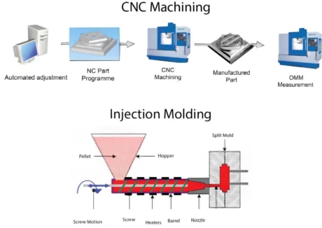
Wyobraź sobie, że masz cyfrowy projekt na swoim ekranie, a zaledwie kilka dni później trzymasz w rękach funkcjonalną, gotową do produkcji część. Dokładnie to umożliwia obróbka prototypów CNC. Ta metoda produkcyjna wykorzystuje sterowanie numeryczne komputerowe, aby przekształcić Twoje pliki CAD w fizyczne prototypy poprzez precyzyjny proces ubytkowy. W przeciwieństwie do druku 3D, który tworzy elementy warstwa po warstwie, prototypowanie CNC usuwa materiał z pełnego bloku, ujawniając Twój projekt z wyjątkową dokładnością.
Od projektu cyfrowego do rzeczywistości fizycznej
Droga od koncepcji do rzeczywistego prototypu rozpoczyna się od Twojego modelu 3D w programie CAD. Ten cyfrowy plik jest konwertowany na kod G – język programowania, który instruuje maszynę, jak dokładnie poruszać się, ciąć i kształtować materiał. Niezależnie od tego, czy potrzebujesz złożonego uchwytu do przemysłu lotniczego, czy prostego elementu mechanicznego, obróbka prototypów CNC stanowi most między wirtualnym projektem a rzeczywistymi testami.
Co wyróżnia to podejście? Od pierwszego dnia pracujesz z rzeczywistymi materiałami produkcyjnymi. Tworząc prototyp frezowany CNC z aluminium, stali lub inżynierskich tworzyw sztucznych, testujesz materiały o tych samych właściwościach, jakie będzie miał końcowy produkt. Eliminuje to niepewność wynikającą z testowania w materiałach zastępczych.
Jak produkcja ubytkowa tworzy precyzyjne prototypy
Dwie główne techniki stanowią podstawę większości projektów obróbki prototypów. Obrót CNC obróbka tokarska doskonale nadaje się do tworzenia części o symetrii obrotowej, takich jak wały, pręty lub cylindry, w których przedmiot obrabiany obraca się, a narzędzia tnące kształtują go. Frezowanie CNC radzi sobie z bardziej złożonymi geometriami, pozwalając na frezowanie powierzchni płaskich, rowków, otworów i kieszonek przy nieruchomym przedmiocie obrabianym.
Podstawowa różnica między prototypowaniem CNC a obróbką produkcyjną wynika z celu i skali. Prototypy służą weryfikacji projektu przed wykorzystaniem znacznych zasobów. Serii produkcyjne stawiają na efektywność i objętość. W fazie prototypowania najważniejsza jest elastyczność. Potrzebujesz swobody testowania, doskonalenia i iterowania bez ograniczeń związanych z narzędziem przeznaczonym do masowej produkcji.
Części, które poddajesz testom, powinny być identyczne z tymi, które ostatecznie zostaną wyprodukowane. Wyroby wykonane metodą CNC w trakcie etapu prototypowania mogą osiągać takie same ścisłe допусki i właściwości materiałowe jak końcowe części produkcyjne, dzięki czemu weryfikacja funkcjonalna nabiera rzeczywistego sensu.
Inżynierowie i deweloperzy produktów polegają na tej metodzie z jednego przekonującego powodu: weryfikacji w warunkach rzeczywistych. Można zweryfikować dopasowanie elementów montażowych, przetestować wydajność mechaniczną pod rzeczywistymi obciążeniami oraz potwierdzić zachowanie termiczne – wszystko to jeszcze przed inwestycją w drogie narzędzia produkcyjne. Dzięki temu podejściu wczesne wykrywanie wad projektowych umożliwia wprowadzanie zmian w niskich kosztach, zamiast odkrywać problemy dopiero po podjęciu decyzji o masowej produkcji.
Podstawowa wartość oferowana przez tę metodę jest prosta. Obróbka prototypów CNC pozwala udowodnić, że zaproponowany koncept działa poprawnie przy użyciu części reprezentatywnych dla produkcji seryjnej, co zmniejsza ryzyko i przyspiesza przejście od pomysłu do produktu gotowego do wprowadzenia na rynek.
Pełny proces obróbki prototypów CNC wyjaśniony krok po kroku
Masz więc już gotowy projekt, który ma zostać przekształcony w fizyczny prototyp. Co dzieje się dalej? Zrozumienie pełnego cyklu pracy pozwala przygotować lepsze pliki, precyzyjniej formułować wymagania oraz ostatecznie otrzymać wyższej jakości części szybciej przejdźmy krok po kroku przez każdy etap – od momentu przesłania pliku CAD aż do chwili, gdy trzymasz gotową część maszyny CNC w swoich rękach.
Siedem etapów tworzenia prototypu
Każdy projekt prototypowania z wykorzystaniem frezarek CNC przebiega według przewidywalnej sekwencji. Znajomość tych etapów pozwala Ci przewidzieć punkty decyzyjne, w których Twoje zaangażowanie ma największe znaczenie.
-
Przesłanie plików projektowych
Twoja podróż zaczyna się od przesłania pliku 3D CAD. Większość warsztatów obróbkowych akceptuje powszechne formaty, takie jak STEP, IGES lub natywne pliki SolidWorks i Fusion 360. Ten cyfrowy rysunek zawiera wszystkie wymiary, krzywizny oraz cechy, jakie musi posiadać Twój prototyp. Na tym etapie dołącz wszelkie rysunki techniczne określające dopuszczalne odchyłki, wykończenia powierzchni lub krytyczne wymiary. Im bardziej precyzyjne będą Twoje wymagania, tym szybciej przejdziesz przez proces przeglądu. -
Analiza przydatności do produkcji (DFM)
To właśnie tutaj doświadczenie inżynierów spotyka się z Twoim projektem. Inżynierowie analizują Twój plik, aby zidentyfikować potencjalne trudności związane z obróbką jeszcze przed rozpoczęciem cięcia. Wskazują one m.in. problemy takie jak wnętrzne narożniki zbyt ostre dla standardowych narzędzi , ściany zbyt cienkie do niezawodnego frezowania lub cechy wymagające niewykonalnych ustawień. Taka współpraca przy przeglądzie zwykle trwa od jednego do dwóch dni roboczych. Oczekuj opinii oraz ewentualnie propozycji drobnych modyfikacji, które nie wpłyną na funkcjonalność, ale poprawią wykonalność produkcyjną i obniżą koszty. -
Dobór materiału
Wybór odpowiedniego materiału to kluczowa decyzja wymagająca Twojego zaangażowania. Czy aluminium zapewni wystarczającą wytrzymałość do testów funkcjonalnych? Czy Twoje zastosowanie wymaga trwałości stali czy specyficznych właściwości tworzyw inżynierskich? Twój partner w zakresie obróbki skrawaniem potwierdzi dostępność materiału i może zalecić alternatywy, jeśli Twój pierwszy wybór stwarza trudności w zakupie. Próby obróbki próbnych elementów są czasem wykonywane z materiałów zastępczych w celu zweryfikowania geometrii przed zainwestowaniem w drogie stopy. -
Programowanie ścieżek narzędzia
Po zatwierdzeniu projektu i potwierdzeniu materiału przejmują go programiści CAM. Korzystają oni ze specjalistycznego oprogramowania, aby dokładnie zaplanować sposób poruszania się narzędzi skrawających w obrębie Twojego materiału. Obejmuje to dobór odpowiednich frezów końcowych, określenie prędkości obrotowej wrzeciona oraz prędkości posuwu oraz zaplanowanie dokładnej kolejności operacji. Można to porównać do stworzenia szczegółowego przepisu, którego będzie się trzymać maszyna CNC. Złożoność programowania zależy od geometrii detalu – od kilku godzin dla prostych komponentów do kilku dni dla skomplikowanych prac wieloosiowych obejmujących operacje frezowania i toczenia CNC. -
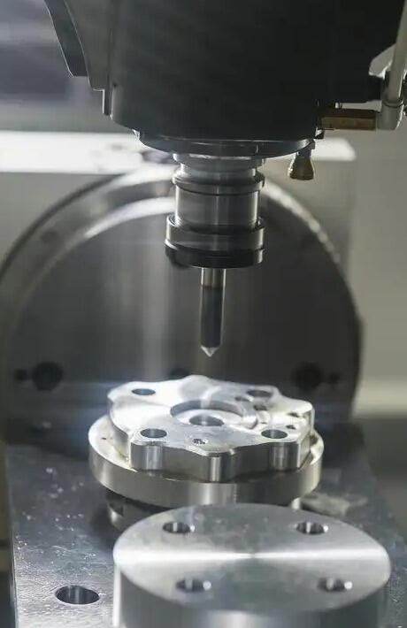
Operacje obróbki skrawaniem
Teraz rozpoczyna się fizyczna transformacja. Operatorzy mocują surowy materiał w maszynie, załadowują wymagane narzędzia tnące oraz ustawiają precyzyjne punkty odniesienia. Następnie maszyna CNC wykonuje zaprogramowane ścieżki narzędzi, usuwając materiał wiórkami, aż pojawi się gotowa część. W zależności od złożoności proces ten może obejmować wiele ustawień, obracanie części w celu uzyskania dostępu do różnych powierzchni lub przenoszenie części między różnymi maszynami. Rzeczywisty czas cięcia waha się od mniej niż godziny dla prostych elementów do kilku dni dla skomplikowanych geometrii wymagających intensywnego usuwania materiału. -
Przetwarzanie
Surowe części obrobione skrawaniem rzadko trafiają bezpośrednio do wysyłki. Etap ten obejmuje usuwanie olejów chłodząco-smarujących i wiórków metalowych, usuwanie wykańczania (zdejmowanie ostrzy) pozostawionych przez narzędzia tnące oraz stosowanie wszelkich określonych metod obróbki powierzchniowej. Możesz zażądać piaskowania w celu uzyskania jednolitego matowego wykończenia, anodowania w celu zwiększenia odporności na korozję aluminium lub polerowania w przypadku prototypów estetycznych. Obróbka końcowa wydłuża czas realizacji, ale często okazuje się niezbędna do przeprowadzenia testów funkcjonalnych lub oceny wizualnej. -
Kontrola jakości
Zanim Twój prototyp zostanie wysłany, podlega weryfikacji. Inspektorzy korzystają z precyzyjnych przyrządów pomiarowych, takich jak suwmiarki, mikrometry oraz maszyny pomiarowe współrzędnościowe (CMM), aby potwierdzić zgodność wymiarów z Twoimi specyfikacjami. W przypadku zastosowań krytycznych możesz otrzymać oficjalne raporty kontrolne dokumentujące rzeczywiste wartości pomiarowe w odniesieniu do Twoich tolerancji. Ten końcowy punkt kontrolny zapewnia, że proces frezowania CNC prototypu dostarczył dokładnie tego, co zaprojektowałeś.
Co dzieje się po przesłaniu plików projektowych
Ciekawi Cię realistyczne ramy czasowe? Oto, czego można oczekiwać w przypadku typowych projektów:
| Scena | Typowy okres trwania | Wymagane dane od klienta? |
|---|---|---|
| Przesłanie plików i wycena | Tego samego dnia do 24 godzin | Tak – przekaż pełne pliki i specyfikacje |
| Przejście DFM | 1–2 dni robocze | Tak – zatwierdź zmiany lub doprecyzuj wymagania |
| Potwierdzenie Materiałów | W tym samym dniu (jeśli dostępny zapas) | Tak – potwierdź wybór materiału |
| Programowanie | 2–8 godzin (proste) do 2+ dni (złożone) | Rzadko wymagane |
| Obróbki | Godziny do dni – w zależności od złożoności | No |
| Przetwarzanie | Od kilku godzin do 1–2 dni | Nie (jeśli określono na wstępie) |
| Inspekcja i wysyłka | Ten sam dzień do 1 dnia | No |
Całkowity czas realizacji prostych prototypów mieści się zwykle w przedziale od trzech do siedmiu dni roboczych. Złożone elementy o ścisłych tolerancjach, wykonane ze specjalnych materiałów lub wymagające intensywnego przetwarzania końcowego mogą wymagać dwóch tygodni lub więcej. Usługi ekspresowe pozwalają znacznie skrócić te terminy, gdy terminy są krytyczne.
Główny wniosek? Przygotowanie projektu ma bezpośredni wpływ na szybkość i jakość realizacji. Kompletne pliki projektowe, wyraźne określenie tolerancji oraz szybkie odpowiedzi w trakcie przeglądu DFM zapewniają nieprzerwaną realizację projektu bez niepotrzebnych opóźnień. Mając solidną wiedzę na temat tego cyklu pracy, jesteś gotowy podjąć świadome decyzje dotyczące wyboru materiałów — a to właśnie kolejny temat, który omówimy.
Wybór odpowiedniego materiału do projektu prototypowego CNC
Masz już gotowy projekt i rozumiesz proces obróbki. Nadszedł teraz jeden z najważniejszych decyzji, jakie podejmiesz: z jakiego materiału ma być wykonany prototyp? Ten wybór wpływa na wszystko – od stopnia, w jakim prototyp oddaje właściwości końcowych części produkcyjnych, po wysokość kosztów i czas oczekiwania.
Oto czego większość poradników nie wspomina. Dobór materiału to nie tylko wybór z listy. Chodzi o dopasowanie właściwości materiału do celu, który chcesz osiągnąć dzięki prototypowi. Czy walidujesz wytrzymałość mechaniczną pod obciążeniem? Testujesz zachowanie termiczne? Sprawdzasz dopasowanie elementów w montażu? Każdy z tych celów wskazuje na inny wybór materiału.
Metale kontra tworzywa sztuczne – jaki materiał wybrać dla Twoich potrzeb prototypowych?
Pierwszy wybór, który staje przed Tobą, jest podstawowy: metal czy tworzywo sztuczne? Każda z tych kategorii pełni inną rolę w procesie tworzenia prototypów, a zrozumienie, kiedy wybrać którąkolwiek z nich, pozwala zaoszczędzić zarówno czas, jak i budżet.
Wybierz metale, gdy potrzebujesz:
- Testowania wytrzymałości i trwałości pod rzeczywistymi obciążeniami
- Walidacja wydajności cieplnej w podwyższonych temperaturach
- Części reprezentujące produkcję do testów certyfikacyjnych
- Prototypy, które staną się funkcjonalnymi elementami końcowego użytku
- Doskonała jakość wykończenia powierzchni po obróbce dodatkowej
Odpadające frezowane aluminium praca konia mocy w zakresie prototypowania metalowego i to z dobrego powodu. Szybko się frezuje, jest tańsze niż stal lub tytan oraz zapewnia doskonałą wytrzymałość przy niskiej masie. Gdy części produkcyjne będą wykonane z aluminium, prototypowanie w tym samym stopie zapewnia dokładne dane dotyczące wydajności bez kompromisów.
Wybierz tworzywa sztuczne, gdy potrzebujesz:
- Walidacji kształtu i dopasowania przed przejściem na metal
- Lekkich komponentów do wstępnego testowania koncepcji
- Opłacalne iteracje w wczesnych fazach projektowania
- Izolacja elektryczna lub określona odporność chemiczna
- Prototypy wizualne do prezentacji dla interesariuszy
Prototyp z tworzywa sztucznego wykonany metodą CNC kosztuje zazwyczaj znacznie mniej niż jego odpowiednik metalowy i jest szybszy w obróbce. Dlatego tworzywa sztuczne są idealne, gdy nadal dopracowujesz geometrię i spodziewasz się wielu iteracji projektowych. Inżynieryjne tworzywa sztuczne, takie jak PEEK lub Delrin, mogą nawet służyć jako prototypy funkcjonalne w wymagających zastosowaniach.
Dopasowanie właściwości materiału do wymagań funkcjonalnych
Zanim przejdziesz do konkretnych materiałów, zadaj sobie następujące pytania:
- Jakie siły będzie podlegał ten prototyp podczas testów?
- Czy temperatura wpływa na moje zastosowanie?
- Czy element będzie narażony na działanie chemikaliów, wilgoci lub promieniowania UV?
- Jak krytyczne są ścisłe tolerancje dla moich celów walidacji?
- Jakie wykończenie powierzchni wymaga moje zastosowanie?
Twoje odpowiedzi kierują doborem materiału w sposób bardziej niezawodny niż jakakolwiek ogólna rekomendacja. Zgodnie z przewodnikiem Jiga dotyczącym doboru materiałów, właściwości materiałów, takie jak twardość, stosunek wytrzymałości do masy, odporność na korozję oraz stabilność termiczna, bezpośrednio decydują o wydajności elementu i ekonomice obróbki skrawaniem.
Popularne materiały stosowane przy prototypowaniu CNC
Poniższe porównanie obejmuje materiały, z którymi najczęściej się spotkasz przy zamawianiu metalowych części obrobionych skrawaniem oraz komponentów plastycznych. Każdy z nich oferuje konkretne zalety w zależności od przeznaczenia prototypu.
| Materiał | Podstawowe właściwości | Najlepsze zastosowania | Uwagi dotyczące obróbki |
|---|---|---|---|
| Aluminum 6061-T6 | Doskonała obrabialność, dobra wytrzymałość, odporność na korozję, lekkość | Ogólne prototypy, obudowy, elementy konstrukcyjne, uchwyty | Łatwo się obrabia, powodując minimalny zużycie narzędzi; osiąga się doskonałe wykończenie powierzchni; dobrze przyjmuje anodowanie |
| Aluminium 7075 | Wysoka wytrzymałość zbliżona do stali, dobra odporność na zmęczenie | Elementy lotnicze i kosmiczne, mocujące elementy narażone na wysokie naprężenia, części wysokowydajne | Twardszy niż 6061, ale nadal dobrze obrabiany; wyższy koszt materiału; mniejsza odporność na korozję |
| Pozostałe stali nierdzewnej | Doskonała odporność na korozję, dobra wytrzymałość, niemagnetyczny | Urządzenia medyczne, przetwórstwo spożywcze, zastosowania morskie | Wymagane niższe prędkości obróbki; materiał ulega wędrowaniu podczas cięcia; większy zużycie narzędzi |
| Nierdzewna stal 316 | Wysoka odporność na korozję, szczególnie wobec chlorków | Sprzęt morski, przetwórstwo chemiczne, sprzęt farmaceutyczny | Podobny do 304, ale nieco trudniejszy w obróbce; materiał o wyższej cenie |
| Mosiądz 360 | Doskonała obracalność, dobra odporność na korozję, atrakcyjna powierzchnia | Końcówki, elementy dekoracyjne, komponenty elektryczne, zawory | Jeden z najłatwiejszych metali do obróbki; zapewnia doskonałe łamania wióra; krótki czas cyklu |
| ABS | Dobra odporność na uderzenia, przystępna cena, łatwy do obróbki | Obudowy, obudowy urządzeń, prototypy wyrobów konsumenckich, modele kształtujące | Łatwe w obróbce maszynowej; należy zwracać uwagę na nagrzewanie się; nadaje się do frezowania CNC tworzyw ABS o skomplikowanych kształtach |
| Akryl (PMMA) | Wysoka przejrzystość optyczna, odporność na zadrapania, stabilność pod wpływem promieniowania UV | Elementy wyświetlaczy, przewodniki światła, wizualne prototypy, soczewki | Wymaga ostrych narzędzi i kontrolowanych posuwów przy frezowaniu CNC akrylu; po polerowaniu osiąga przejrzystość optyczną |
| Delrin (acetal/POM) | Niskie tarcie, doskonała stabilność wymiarowa, dobra wytrzymałość | Zębniki, łożyska, precyzyjne elementy mechaniczne, wpuszczki | Wyd exceptionalna łatwość obróbki; minimalne pochłanianie wilgoci; zachowuje ścisłe допусki |
| PEEK | Odporność na wysokie temperatury (250 °C), odporność chemiczna, duża wytrzymałość | Wnętrza samolotów, implanty medyczne, sprzęt półprzewodnikowy | Wymaga niższych prędkości skrawania; materiał kosztowny; doskonały w wymagających środowiskach |
| Nylon (PA) | Wytrzymał, odporny na zużycie, samosmarujący | Zębniki, wałki toczne, elementy narażone na zużycie, części konstrukcyjne | Wchłania wilgoć, co wpływa na wymiary; dobrze się obrabia, ale może być „ciągliwy” |
Materiały specjalistyczne, które warto znać
Ponad standardowe metale i tworzywa sztuczne, niektóre zastosowania wymagają materiałów specjalistycznych. Obróbka CNC ceramiki służy do ekstremalnych warunków termicznych i chemicznych; materiały takie jak Macor czy azotek glinu umożliwiają produkcję komponentów wytrzymujących warunki, których żaden metal ani tworzywo sztuczne nie jest w stanie znieść. Jednak te materiały wymagają specjalistycznego narzędzi i wiedzy fachowej, co znacznie zwiększa koszty oraz czas realizacji.
Stopy tytanu oferują wyjątkowe stosunki wytrzymałości do masy oraz biokompatybilność, co czyni je niezbędny w prototypowaniu dla przemysłu lotniczego i medycznego. Najczęściej stosowaną odmianą jest tytan stopowy klasy 5 (Ti-6Al-4V), choć jego obróbka przebiega wolniej niż aluminium i przyspiesza zużycie narzędzi.
Wykończenie powierzchni oraz zgodność z procesami obróbki wtórnej
Wybór materiału ma bezpośredni wpływ na dostępne opcje wykończenia. Weź pod uwagę następujące czynniki kompatybilności:
- Anodowanie działa wyłącznie z aluminium, tworząc trwałe, barwione warstwy tlenkowe
- Elektroliterowanie nadaje się do większości metali, ale wymaga przewodzących podłoży
- Malowanie proszkowe dobrze przyczepia się do metali oraz niektórych tworzyw sztucznych odpornych na wysokie temperatury
- Polerowanie daje najlepsze rezultaty na materiałach gęstych, takich jak stal nierdzewna, mosiądz i akryl
- Malarstwo działa na niemal wszystkich materiałach przy odpowiednim przygotowaniu powierzchni
Jeśli prototyp wymaga określonego wykończenia w celu oceny estetycznej lub testów funkcjonalnych, upewnij się przed zamówieniem, że wybrany materiał jest kompatybilny z tą metodą wykończenia.
Podjęcie decyzji
Przy wyborze materiałów na prototyp CNC należy uwzględnić następujące czynniki w podanej kolejności:
- Wymagania funkcjonalne - Jakie właściwości musi wykazywać prototyp?
- Zamiar produkcyjny - Czy końcowe części będą wykonywane z tego samego czy podobnego materiału?
- Ograniczenia budżetowe - W jaki sposób koszty materiału i obróbki skrawaniem wpisują się w ekonomikę projektu?
- Wymagania dotyczące harmonogramu - Czy dostępność materiału pozwala na realizację harmonogramu?
Według Protolabs , użycie tego samego żywicy do prototypów wykonanych metodą frezowania CNC, co do ostatecznej produkcji metodą wtrysku, zapewnia prototypy zachowujące się podobnie jak końcowe części, dzięki czemu wyniki testów są rzeczywiście przewidywalne.
Wybór materiału ma większy wpływ na sukces prototypowania niż jakiekolwiek inne pojedyncze decyzje. Dobór odpowiedniego materiału dostosowanego do celów testowych umożliwia uzyskanie istotnej weryfikacji. Jednak jak prototypowanie CNC porównuje się do innych metod, takich jak druk 3D, jeśli projekt może pójść w dowolnym z tych kierunków? To właśnie przeanalizujemy w kolejnym punkcie.
Prototypowanie CNC kontra druk 3D i inne metody szybkiego prototypowania
Wybrałeś/-aś materiał i rozumiesz przepływ pracy CNC. Ale warto zadać sobie pytanie: czy obróbka CNC jest rzeczywiście odpowiednim wyborem dla Twojego prototypu? Czasami jest to absolutnie najlepsza opcja. W innych przypadkach druk 3D lub inne metody pozwalają uzyskać lepsze rezultaty za mniejszą kwotę. Wiedza, kiedy stosować każdą z tych metod, pozwala zaoszczędzić czas, budżet oraz uniknąć rozczarowania.
Zajmijmy się rzeczami istotnymi i przeanalizujmy, kiedy szybka obróbka CNC rzeczywiście przewyższa alternatywy, a kiedy warto wziąć pod uwagę zupełnie inne podejście.
Kiedy CNC przewyższa druk 3D i odwrotnie
Obie technologie odgrywają ważną rolę w rozwoju produktów, ale rozwiązują różne problemy. Zgodnie z danymi firmy Hubs, obróbka CNC zapewnia wyższą dokładność wymiarową oraz spójne właściwości mechaniczne we wszystkich trzech osiach, podczas gdy druk 3D wyróżnia się w przypadku dużej elastyczności projektowej lub złożonych geometrii.
Frezowanie CNC jest lepszym rozwiązaniem, gdy:
- Wymagasz ścisłych tolerancji, których metody addytywne po prostu nie są w stanie osiągnąć
- Testy funkcjonalne wymagają właściwości materiałów stosowanych w produkcji
- Wykończenie powierzchni ma znaczenie, a chcesz jak najmniejszą liczbę operacji końcowych
- Twój prototyp będzie poddawany obciążeniom mechanicznym lub podwyższonym temperaturom
- Pracujesz z metalami, w których izotropowa wytrzymałość jest warunkiem bezwzględnie koniecznym
druk 3D odnosi zwycięstwo, gdy:
- Twoje projekt obejmuje złożone geometrie wewnętrzne, struktury siatkowe lub cechy zoptymalizowane pod kątem topologii
- Potrzebujesz części w ciągu 24 godzin, a szybkość ma pierwszeństwo przed precyzją
- Ilości są bardzo niskie, często poniżej 10 sztuk
- Korzystasz z materiałów specjalnych, takich jak elastyczny TPU, który trudno obrabiać skrawaniem
- Ograniczenia budżetowe sprawiają, że każda metoda szybkiego prototypowania CNC jest zbyt kosztowna na wczesne iteracje
Oto czego wiele poradników nie powie wam: warstwowa natura druku 3D powoduje, że wydrukowane elementy mają właściwości anizotropowe. Oznacza to, że wydrukowane części są często słabsze wzdłuż linii warstw, co ma istotne znaczenie podczas testów funkcjonalnych. Gdy chcecie zweryfikować, jak dana część zachowuje się pod obciążeniem, szybkie prototypowanie frezarskie z użyciem rzeczywistych materiałów produkcyjnych zapewnia wiarygodne dane, których nie można uzyskać przy użyciu wydruków 3D.
Wybór między metodami ubytkowymi a przyrostowymi
Decyzja nie zawsze musi być binarna. Sprytne zespoły rozwijające produkty często stosują obie te technologie strategicznie na różnych etapach projektu. Firma Fictiv zauważa, że podejście hybrydowe najczęściej przynosi najlepsze rezultaty: druk 3D na wczesnym etapie iteracji projektowych, a następnie szybkie prototypowanie CNC do końcowej weryfikacji funkcjonalnej.
Ponad te dwie główne metody procesy odlewania poliuretanowego oraz miękkiego formowania oferują cenne alternatywy w określonych sytuacjach. Rozważcie poniższą macierz decyzyjną przy ocenie dostępnych opcji:
| Czynnik | Obróbka CNC | druk 3D (SLS/FDM) | Odlewanie poliuretanowe | Wyposażenie miękkie |
|---|---|---|---|---|
| Opcje materiałowe | Szeroki wybór – metale, tworzywa sztuczne, kompozyty o właściwościach odpowiadających poziomowi produkcji przemysłowej | Rosnący wybór – tworzywa sztuczne, niektóre metale; właściwości zależą od zastosowanej technologii | Ograniczony do formuł poliuretanowych naśladujących różne tworzywa sztuczne | Termoplasty przeznaczone do produkcji masowej przy użyciu form aluminiowych |
| Dopuszczalność | Doskonała – zwykle osiągalna dokładność wynosi ±0,025 mm do ±0,125 mm | Średnia – zwykle dokładność wynosi ±0,1 mm do ±0,3 mm w zależności od zastosowanej technologii | Dobra – typowa dokładność wynosi ±0,15 mm do ±0,25 mm | Dobra – dokładność zbliżona do precyzji wtryskiwania |
| Opracowanie powierzchni | Doskonała – gładka powierzchnia bezpośrednio po obróbce skrawaniem; umożliwia stosowanie wszystkich metod wykańczania | Widoczne linie warstw w większości procesów; często wymagana obróbka końcowa | Dobrze – odtwarza jakość powierzchni modelu wzorcowego | Doskonałe – wykończenie na poziomie produkcji przemysłowej |
| Koszt przy 1–5 sztukach | Umiarkowany do wysokiego – koszty przygotowania rozłożone na niewielką liczbę elementów | Niski – minimalne koszty przygotowania, płaci się tylko za materiał i czas | Umiarkowany – wymaga modelu wzorcowego oraz formy | Wysoki – inwestycja w narzędzia przy małej liczbie sztuk |
| Koszt przy 20–50 sztukach | Konkurencyjny – koszty przygotowania rozłożone na większą ilość | Rosnący – liniowe skalowanie kosztów staje się drogie | Opłacalne – formy silikonowe pozwalają na wykonanie 20–30 odlewów | Staje się opłacalne – koszty narzędzi rozkładają się na większą liczbę części |
| Czas Oczekiwania | 3–10 dni – typowy czas realizacji w warsztatach szybkiego frezowania CNC | 1–5 dni – najkrótszy czas dla prostych geometrii | 5–15 dni – obejmuje wykonanie wzorca i formy | 2–4 tygodnie – projektowanie i produkcja narzędzi |
| Złożoność geometryczna | Ograniczone przez dostęp do narzędzia – trudne do wykonania cechy wewnętrzne | Doskonałe – kanały wewnętrzne, struktury kratowe, kształty organiczne | Umiarkowane – możliwość wykonania podcięć przy użyciu wieloczęściowych form | Umiarkowane – ograniczenia podobne do tych występujących w formowaniu wtryskowym |
Kiedy CNC NIE jest najlepszym wyborem
Szczera ocena ma większe znaczenie niż promowanie jakiegokolwiek pojedynczego rozwiązania technologicznego. Szybkie prototypowanie metodą frezowania CNC nie jest optymalne w przypadku:
- Geometria zawiera niedostępne elementy wewnętrzne. Złożone kanały wewnętrzne, zamknięte wnęki lub organiczne struktury siatkowe, do których narzędzia skrawające po prostu nie mogą dotrzeć, czynią druk 3D wyraźnym liderem.
- Potrzebujesz jednej lub dwóch sztuk do wizualizacji koncepcji. W przypadku prostych modeli kształtów, gdzie właściwości mechaniczne nie mają znaczenia, druk 3D na biurkowym drukarce kosztuje ułamek cen frezowania i umożliwia dostarczenie gotowego produktu już następnego dnia.
- Budżet jest mocno ograniczony w wczesnej fazie generowania pomysłów. Gdy spodziewasz się pięciu lub więcej iteracji projektowych przed ostatecznym ustaleniem geometrii, zużywanie budżetu przeznaczonego na frezowanie na częściach, które później zostaną odrzucone, nie ma sensu ekonomicznego.
- Pracujesz z materiałami zoptymalizowanymi pod kątem procesów addytywnych. Elastyczny TPU, niektóre metaliczne stopy superstopowe oraz kompozyty wypełnione drobinkami drewna lepiej sprawdzają się w technologii druku niż w obróbce skrawaniem.
Według RAPIDprototyping.nl przy próbkowaniu szybkim proces odlewania w próżni staje się szczególnie atrakcyjny, gdy potrzebujesz 20–30 identycznych prototypów wykonanych z materiałów symulujących termoplasty stosowane w produkcji. Forma silikonowa wytworzona na podstawie modelu wzorcowego wykonanego metodą SLA umożliwia spójną reprodukcję przy niższych kosztach jednostkowych niż frezowanie lub druk 3D w takiej ilości.
Podjęcie właściwej decyzji dla Twojego projektu
Rozważ poniższe praktyczne wytyczne przy podejmowaniu decyzji:
- Do testów funkcjonalnych pod rzeczywistymi obciążeniami: Próbkowanie szybkie z zastosowaniem frezowania CNC pozostaje standardem złotym, ponieważ testujesz rzeczywiste materiały produkcyjne o izotropowych właściwościach.
- Dla ilości od 10 do 50 sztuk: Odlewanie poliuretanowe często stanowi optymalny kompromis między kosztem jednostkowym a akceptowalnym czasem realizacji.
- Dla skomplikowanych geometrii z precyzyjnymi tolerancjami wymiarowymi na powierzchni zewnętrznej: Rozważ podejście hybrydowe: wydrukuj trójwymiarowo skomplikowany rdzeń, a następnie przefrezuj krytyczne powierzchnie stykowe zgodnie ze specyfikacją.
- Dla objętości produkcji powyżej 500 sztuk: Ani frezowanie CNC, ani druk 3D mogą nie być optymalne. Formowanie wtryskowe lub inne technologie kształtowania zapewniają zazwyczaj lepszą opłacalność przy dużych skalach produkcji.
Najskuteczniejsze strategie prototypowania dobierają metodę do etapu projektowania. Wczesne koncepcje mogą wykorzystywać druk FDM ze względu na szybkość i niski koszt. Prototypy średniego etapu mogą korzystać z druku SLS w celu uzyskania wyższej dokładności. Prototypy końcowe służące walidacji często wymagają frezowania CNC, aby potwierdzić zgodność z parametrami produkcyjnymi.
Teraz, gdy rozumiesz, kiedy prototypowanie CNC przynosi największą wartość, przeanalizujmy, jak zoptymalizować swoje projekty specyficznie pod kątem tej metody wytwarzania. Poprawna przygotowana dokumentacja konstrukcyjna zmniejsza liczbę iteracji, obniża koszty oraz przyspiesza harmonogram realizacji.
Zasady projektowania z myślą o możliwościach produkcyjnymi (DFM) dla prototypów CNC
Wybrałeś metodę prototypowania i materiały. Nadszedł teraz etap, który oddziela płynne projekty od uciążliwych opóźnień: przygotowanie projektu do rzeczywistej obróbki skrawaniem. Wyobraź sobie to w ten sposób: model CAD może wyglądać idealnie na ekranie, ale maszyny CNC działają w świecie fizycznym, gdzie narzędzia skrawające mają minimalne średnice, materiały mogą ulegać odkształceniom pod wpływem nacisku, a niektóre geometrie po prostu nie są osiągalne.
Projektowanie z myślą o obróbce skrawaniem nie ogranicza kreatywności. Chodzi raczej o przetłumaczenie intencji projektowych na formę, którą maszyny są w stanie wykonać efektywnie. Poprawne wykonanie tego etapu przed przesłaniem plików eliminuje kosztowne poprawki, skraca czas obróbki i zapewnia uzyskanie frezowanych elementów zgodnych z Twoimi specyfikacjami już za pierwszym razem.
Zasady projektowania oszczędzające czas i pieniądze
Każda maszyna CNC ma swoje ograniczenia fizyczne. Narzędzia skrawające wirują z dużymi prędkościami, usuwają materiał stopniowo i muszą fizycznie uzyskać dostęp do każdej cechy, którą mają tworzyć. Zrozumienie tych rzeczywistości pozwala na mądrzejsze projektowanie od samego początku.
Minimalna grubość ściany
Cienkie ścianki stwarzają prawdziwe problemy podczas obróbki. Ulegają one drganiom przy kontakcie z narzędziami skrawającymi, uginają się pod wpływem nacisku narzędzia i mogą ulec odkształceniu wskutek ciepła generowanego podczas cięcia. Zgodnie z Wytycznymi projektowymi Geomiq , minimalna grubość ścianek powinna wynosić co najmniej 0,8 mm dla metali i 1,5 mm dla tworzyw sztucznych, aby zapewnić stabilność. Wyższe ścianki wymagają jeszcze większej grubości. Dobrą zasadą jest utrzymanie stosunku szerokości do wysokości na poziomie 3:1 lub lepszym dla ścianek niepodpartych.
Promienie narożników wewnętrznych
Oto coś, co często przeocza wielu projektantów: części frezowane CNC są obrabiane za pomocą wirujących narzędzi walcowych, które fizycznie nie są w stanie wytworzyć idealnie ostrych naroży wewnętrznych. Każde wewnętrzne naroże będzie miało promień równy co najmniej promieniowi użytego narzędzia skrawającego. Chcesz mniejszych promieni? Wymaga to zastosowania mniejszych narzędzi, które skrawają wolniej i szybciej się zużywają, co zwiększa koszty.
Projektuj wewnętrzne narożniki z promieniami co najmniej o 30 % większymi niż promień używanego narzędzia frezarskiego. Na przykład, jeśli do obróbki stosowany jest frez końcowy o średnicy 6 mm, należy określić promienie wewnętrzne równe co najmniej 4 mm. Takie założenie zmniejsza obciążenie narzędzia, zwiększa prędkość skrawania oraz minimalizuje widoczne ślady frezowania, które często powstają przy bardziej ostrych narożnikach.
Stosunek głębokości otworu do jego średnicy
Standardowe wiertła pozwalają efektywnie wykonywać otwory o głębokości do około czterokrotnej średnicy wiertła. Przy większych głębokościach usuwanie wióra staje się problematyczne, a ugięcie narzędzia rośnie. Dla otworu o średnicy 10 mm utrzymanie głębokości poniżej 40 mm zapewnia bezproblemową obróbkę. Głębsze otwory wymagają specjalistycznego narzędzi, cykli wiercenia z przerywaniem lub innych rozwiązań, co zwiększa czas i koszty produkcji.
Uwagi dotyczące głębokości wnęk
Podobna zasada dotyczy również wnęk i zagłębień. Narzędzia frezarskie działają najefektywniej przy głębokościach do trzykrotnej średnicy narzędzia. Przy większych głębokościach konieczne są dłuższe narzędzia, które są bardziej podatne na ugięcie i drgania. Należy, o ile to możliwe, ograniczać głębokość wnęki do wartości nieprzekraczającej czterokrotnej szerokości wnęki.
Dostępność podcięć
Standardowe frezarki CNC o trzech osiach mają dostęp do cech wyłącznie od góry. Jeśli projekt zawiera podcięcia, ukryte kieszenie lub cechy zablokowane przez wystające geometrie, maszyna po prostu nie jest w stanie ich osiągnąć bez specjalnych ustawień. Rozważ, czy podcięcia są rzeczywiście konieczne, czy też tę samą funkcję można osiągnąć przy użyciu geometrii dostępnej dla narzędzia.
Skumulowanie tolerancji
Ścisłe tolerancje są droższe. Znacznie droższe. Standardowa tolerancja frezowania wynosząca ±0,13 mm doskonale spełnia wymagania większości zastosowań. Określenie tolerancji ±0,025 mm dla każdej wymiaru znacznie wydłuża czas kontroli, wymaga niższych prędkości skrawania i może wymagać zastosowania specjalistycznego sprzętu. Ścisłe tolerancje należy zarezerwować wyłącznie dla powierzchni stykających się oraz kluczowych wymiarów funkcyjnych, gdzie rzeczywiście mają one znaczenie.
Unikanie typowych błędów geometrycznych
Nawet doświadczeni projektanci popełniają te błędy. Wykrycie ich przed przesłaniem projektu pozwala zaoszczędzić czas wszystkim zaangażowanym stronom i utrzymuje projekt w harmonogramie.
- Ostre narożniki wewnętrzne w całym elemencie. Pamiętaj, że narzędzia tnące są okrągłe. Dodaj odpowiednie promienie zaokrąglenia do wszystkich narożników wewnętrznych zgodnie z przewidywanymi rozmiarami narzędzi. Narożniki zewnętrzne mogą pozostać ostre, ponieważ narzędzia tworzą je naturalnie.
- Niepotrzebnie głębokie wgłębienia. To wgłębienie o głębokości 50 mm i szerokości 8 mm wygląda dobrze w oprogramowaniu CAD, ale wymaga specjalistycznych narzędzi o dużej długości roboczej, które uginają się i drżą. Zmodyfikuj projekt głębokich i wąskich cech, jeśli to możliwe, lub zaakceptuj fakt, że będą one znacznie droższe.
- Nadmiernie ścisłe tolerancje dla wymiarów niekrytycznych. Stosowanie tolerancji ±0,05 mm do każdego wymiaru powoduje niepotrzebne wydatki. Standardowe tolerancje są wystarczające dla większości cech. Ścisłe tolerancje należy określać wyłącznie tam, gdzie tego wymaga funkcja elementu.
- Tekst i logotypy bez nachylenia (draft). Wytłaczany tekst o idealnie pionowych ściankach wymaga małych narzędzi i niskich prędkości posuwu. Dodanie lekkiego nachylenia (draft) do liter przyspiesza obróbkę i często poprawia czytelność.
- Niestandardowe średnice otworów. Standardowe rozmiary wiertła pozwalają szybko i precyzyjnie wykonać otwory. Do otworów o niestandardowych średnicach konieczne jest stosowanie frezów czołowych w celu stopniowego usuwania materiału, co znacznie wydłuża czas obróbki. Sprawdź tabele standardowych średnic wiertła przed określeniem średnicy otworów.
- Ignorowanie ograniczeń głębokości gwintu. Wytrzymałość gwintu zależy przede wszystkim od pierwszych kilku zwojów. Określanie głębokości gwintu większej niż trzykrotność średnicy otworu marnuje czas obróbki. W przypadku otworów ślepych pozostaw niegwintowaną część o długości równej połowie średnicy otworu przy jego dnie.
- Projektowanie elementów wymagających obróbki metodą EDM. Prawdziwie ostre narożniki wewnętrzne, bardzo wąskie wpadki oraz niektóre złożone geometrie można wykonać wyłącznie metodą elektroerozyjną (EDM). Proces ten jest znacznie droższy i czasochłonniejszy niż standardowa frezarka CNC.
- Zapominanie o uchwytach. Twój detal musi być solidnie zamocowany podczas obróbki. Konstrukcje bez płaskich powierzchni do mocowania lub detale zbyt cienkie do chwytania powodują trudności w przygotowaniu ustawienia. Przy projektowaniu kluczowych powierzchni należy wziąć pod uwagę sposób, w jaki detal będzie zamocowany.
Formaty plików i przygotowanie modelu
Jakość pliku projektowego ma bezpośredni wpływ na szybkość przejścia projektu przez etap programowania. Zgodnie z wytycznymi Dipec dotyczącymi przygotowywania plików, prawidłowo sformatowane pliki eliminują nieporozumienia i zapobiegają błędom skalowania, które mogą zatrzymać produkcję.
Preferowane formaty plików:
- STEP (.step, .stp) - Standard branżowy służący do przesyłania geometrii 3D między różnymi systemami CAD. Zachowuje krzywe i powierzchnie z dużą dokładnością.
- IGES (.iges, .igs) - Kolejny uniwersalny format, choć starszy. Działa dobrze dla prostszych geometrii.
- Natywne pliki CAD - Pliki SolidWorks, Fusion 360 lub Inventor są stosowane, gdy partner wykonawczy korzysta z kompatybilnego oprogramowania.
- Rysunki w formacie PDF - Zawsze dołączaj rysunki 2D dla detali z krytycznymi tolerancjami, wymaganiami dotyczącymi chropowatości powierzchni lub uwagami montażowymi.
Zanim prześlesz:
- Sprawdź, czy jednostki są poprawne. Przypadkowe przesłanie modelu w milimetrach, który zostanie zinterpretowany jako calowy, spowoduje wytworzenie części o rozmiarze 25 razy większym niż zamierzony.
- Upewnij się, że model jest szczelny, bez otwartych powierzchni ani szczelin.
- Usuń ukryte cechy oraz nieużywane szkice, które mogą wprowadzić w błąd programowanie.
- Ustaw początek układu współrzędnych modelu w logicznym punkcie odniesienia.
- Przekonwertuj wszelki tekst na geometrię lub kontury.
Poprawne przygotowanie projektu nie polega wyłącznie na unikaniu błędów. Chodzi również o poszanowanie praw fizyki związanej z obróbką skrawaniem oraz osiągnięcie funkcjonalnych celów projektowych. Każda godzina poświęcona optymalizacji projektu pod kątem możliwości produkcyjnych pozwala zaoszczędzić wiele godzin na etapie obróbki CNC, zmniejsza odpady materiału oraz przyspiesza dostarczanie działających prototypów.
Gdy projekt został zoptymalizowany pod kątem produkcji CNC, możesz przejść do analizy sposobu, w jaki różne branże stosują te zasady do swoich specyficznych wymagań. Sektor lotniczy, medyczny, motocyklowy oraz elektroniki konsumenckiej stawiają unikalne wymagania, które kształtują specyfikacje prototypów.
Zastosowania przemysłowe – od przemysłu lotniczego po urządzenia medyczne
Projekt został zoptymalizowany, a materiał dobrany. Ale istnieje coś, co w sposób podstawowy kształtuje każdą z dotychczasowych decyzji: branża, dla której przeznaczony jest prototyp. Uchwyt przeznaczony do zastosowania w samolocie podlega zupełnie innym wymaganiom niż obudowa urządzenia konsumenckiego. Zrozumienie tych specyficznych dla danej branży wymagań pozwala określić odpowiednie допuszczalne odchylenia wymiarowe, wybrać odpowiednie materiały oraz przygotować się do dokumentacji wymaganej przez dane zastosowanie.
Przyjrzymy się, jak cztery główne branże podejmują zagadnienie obróbki CNC prototypów i jakie to ma konsekwencje dla specyfikacji Państwa projektu.
Wymagania dotyczące dopuszczalnych odchyleni wymiarowych i materiałów zależne od sektora
Różne branże wypracowały przez dziesięciolecia doświadczenia produkcyjnego własne, odmienne oczekiwania. To, co uznawane jest za dopuszczalne w elektronice użytkowej, natychmiast zawiedzie w przemyśle lotniczo-kosmicznym. Wiedza na temat miejsca, jakie zajmuje prototyp w danej kategorii, pozwala jasno komunikować wymagania oraz unikać nadmiernego lub niedostatecznego określenia kluczowych wymiarów.
Przemysł lotniczy
Gdy komponenty działają na wysokości 40 000 stóp pod wpływem skrajnych obciążeń, standardowe допусki po prostu nie wystarczają. Zgodnie z Przewodnik TPS Elektronik dotyczący precyzyjnej obróbki skrawaniem , zastosowania lotniczo-kosmiczne wymagają zazwyczaj dopuszczeń wynoszących ±0,0005 cala, co jest znacznie ścislsze niż ogólne normy produkcyjne.
- Wymagania dotyczące tolerancji: Zazwyczaj ±0,0005 cala lub ścislsze dla części CNC krytycznych dla bezpieczeństwa lotu. W razie absolutnej konieczności specjalistyczne ustawienia pozwalają osiągnąć dopuszczalne odchylenia na poziomie ±0,0001 cala.
- Wymagania materiałowe: Stopy tytanu, Inconel oraz aluminium klasy lotniczej dominują w tej dziedzinie. Te egzotyczne stopy charakteryzują się wyjątkowym stosunkiem wytrzymałości do masy, ale wymagają zastosowania specjalistycznego narzędzi i niższych prędkości frezowania.
- Oczekiwania dotyczące śledzalności: Kompletna dokumentacja, obejmująca certyfikaty surowców aż po końcową inspekcję. Każdy detal frezowany CNC musi być śledzony wstecz do źródła materiału, partii termicznej oraz historii obróbki.
- Wymagania certyfikacyjne: Dostawcy muszą spełniać standardy AS9100. Zgodność z wymogami ITAR jest obowiązkowa w przypadku komponentów związanych z obronnością.
- Specyfikacje wykańczania powierzchni: Często 32 Ra lub lepiej dla powierzchni aerodynamicznych i obszarów krytycznych pod względem zmęczeniowym.
Prototypy lotnicze często pełnią funkcję artykułów testowych, którym poddawane są te same obciążenia co komponenty produkcyjne. Oznacza to, że wykonywane przez Państwa detale obrabiane skrawaniem muszą działać identycznie jak końcowe elementy produkcyjne.
Przemysł motoryzacyjny
Prototypowanie motocyklowe i samochodowe łączy walidację właściwości użytkowych z ekonomiką produkcji. Prototypy muszą dokładnie odzwierciedlać zachowanie się części produkcyjnych podczas testów trwałości, jednocześnie spełniając rygorystyczne harmonogramy rozwoju.
- Wymagania dotyczące tolerancji: Ogólnie ±0,001 cala do ±0,005 cala w zależności od systemu. Komponenty układu napędowego wymagają ścislszych tolerancji niż panele nadwozia.
- Wymagania materiałowe: Materiały reprezentatywne dla produkcji są niezbędne. Testowanie prototypu ze stali w przypadku, gdy w produkcji stosowany jest aluminium, czyni dane dotyczące wydajności nieprawidłowymi.
- Znaczenie testów funkcjonalnych: Prototypy podlegają walidacji odporności na zużycie, cyklowaniu termicznemu oraz weryfikacji montażu. Precyzyjne frezowanie i toczenie metalowych części metodą CNC zapewnia elementy wytrzymujące warunki rzeczywistych testów.
- Wymagania certyfikacyjne: Certyfikat IATF 16949 potwierdza dojrzałość systemu zarządzania jakością. Dokumentacja dotycząca statystycznej kontroli procesów (SPC) często towarzyszy dostarczanym częściami.
- Oczekiwania co do objętości: W programach motocyklowych i samochodowych często wymagane jest od 10 do 50 jednostek prototypowych do przeprowadzenia testów na wielu lokalizacjach, co czyni efektywność kosztową ważną nawet na etapie prototypowania.
Przemysł Urządzeń Medycznych
Bezpieczeństwo pacjenta kieruje każdą decyzją podejmowaną w trakcie prototypowania urządzeń medycznych. Wymagania regulacyjne nakładają dodatkowe warstwy dokumentacji oraz ograniczenia materiałowe, których nie ma w innych sektorach. Zgodnie z przeglądem technologii obróbki urządzeń medycznych firmy BOEN Rapid, zgodność z przepisami FDA oraz normą ISO 13485 jest obowiązkowa, a nie opcjonalna.
- Wymagania biokompatybilności: Materiały muszą być zgodne ze standardami ISO 10993. Typowymi materiałami są stal nierdzewna przeznaczona do zastosowań medycznych (316L), tytan (Ti-6Al-4V ELI) oraz PEEK w zastosowaniach implantacyjnych.
- Wymagania dotyczące wykończenia powierzchni: Gładkie powierzchnie zmniejszają przyczepność bakterii i ułatwiają czyszczenie. Powierzchnie implantów często wymagają określonych wartości chropowatości Ra, które muszą być udokumentowane w raportach inspekcyjnych.
- Dokumentacja regulacyjna: Zasady jakościowe FDA (rozdział 21 CFR część 820) wymagają udokumentowania procedur dla każdego etapu produkcji. Certyfikat ISO 13485 zapewnia ramy systemu zarządzania jakością.
- Integracja zarządzania ryzykiem: ISO 14971 wymaga udokumentowanej analizy ryzyka dla urządzeń medycznych. Proces frezowania prototypu staje się częścią tej dokumentacji ryzyka.
- Wymagania dotyczące walidacji: Walidacja procesu musi potwierdzać uzyskiwanie spójnych i powtarzalnych wyników. Dotyczy to również ilości prototypowych w przypadku projektów przeznaczonych do produkcji.
Elektronika konsumencka
Produkty konsumenckie kładą nacisk na estetykę równie mocno jak na funkcjonalność. Prototyp może pojawić się w prezentacjach dla interesariuszy, grupach fokusowych lub na zdjęciach marketingowych jeszcze przed przeprowadzeniem testów technicznych.
- Wymagania dotyczące tolerancji: Średnie допусki wynoszące ±0,005 cala zwykle wystarczają dla obudów. Ścisłe tolerancje stosuje się do elementów montażowych wewnętrznych komponentów.
- Priorytety estetyczne: Jakość wykończenia powierzchni często ma większe znaczenie niż precyzja wymiarowa. Prototypy muszą wyglądać i odczuwać się tak jak jednostki produkcyjne.
- Zakres testów montażu: Prototypy służą weryfikacji dopasowania poszczególnych komponentów, odczuwania przycisków oraz dokładności dopasowania wyświetlaczy do obudów.
- Reprezentacja materiałów: Choć w produkcji masowej stosuje się wtrysk plastiku, to części wykonane metodą frezowania CNC z podobnych tworzyw sztucznych lub aluminium pozwalają zweryfikować kształt i funkcjonalność.
- Oczekiwania dotyczące szybkości: Cykle rozwoju urządzeń elektronicznych przeznaczonych dla konsumentów są bardzo napięte. Szybkie dostarczanie prototypów często ma większą wagę niż osiągnięcie najścislszych możliwych tolerancji.
Jak wymagania branżowe kształtują specyfikacje prototypów
Zrozumienie różnic między sektorami pozwala lepiej komunikować się ze swoim partnerem z zakresu obróbki skrawaniem. Gdy zamawiasz części frezowane CNC do zastosowań lotniczych, dostawca natychmiast rozumie wymagania dotyczące dokumentacji, śledzalności oraz intensywności kontroli jakości. Określenie, że część ma być używana w urządzeniach medycznych, wywołuje pytania dotyczące certyfikatów materiałów oraz weryfikacji chropowatości powierzchni.
Wymagania dotyczące dokumentacji różnią się znacznie:
- Lotnictwo i astronautyka: Certyfikaty materiałów, śledzalność partii cieplnych, raporty pomiarów wymiarowych, certyfikaty procesów (AS9100, zgodność z przepisami ITAR)
- Motoryzacja: Raporty pierwszej kontroli artykułu (FAI), badania zdolności procesu (dane Cpk), raporty badań materiałów, dokumentacja PPAP dla prototypów przeznaczonych do produkcji
- Medyczna: Certyfikaty biokompatybilności materiałów, pomiary chropowatości powierzchni, dokumentacja walidacji procesów, rejestry zarządzania ryzykiem
- Konsument: Zazwyczaj minimalna dokumentacja, chyba że została ona wyraźnie określona. Uwaga skupia się na weryfikacji jakości wizualnej oraz dopasowania.
Kryteria akceptacji różnią się również w zależności od sektora. W przemyśle lotniczym część może zostać odrzucona z powodu pojedynczego wymiaru odchylającego się o 0,0002 cala od dopuszczalnej tolerancji. W przemyśle elektroniki użytkowej takie samo odchylenie może być zaakceptowane bez obaw. Przekazanie kontekstu branżowego ułatwia partnerowi z zakresu obróbki CNC zastosowanie odpowiedniego poziomu rygoru kontrolnego.
Te specyficzne dla danej branży wymagania mają bezpośredni wpływ na koszty projektu. Ścislsze допуски, materiały egzotyczne oraz obszerne dokumentacja zwiększają wydatki. Zrozumienie rzeczywistych wymagań aplikacji pozwala na właściwe określenie specyfikacji bez nadmiernego inżynierowania, co umożliwia kontrolę budżetu prototypów przy jednoczesnym spełnieniu rzeczywistych potrzeb funkcjonalnych.
Zrozumienie kosztów i czynników wpływających na cenę prototypów wykonanych metodą CNC
Zoptymalizowałeś swój projekt i znasz wymagania branżowe. Teraz pojawia się pytanie, które zadaje sobie każdy, ale na które niewiele źródeł odpowiada szczerze: ile to będzie kosztować? W przeciwieństwie do produktów komoditycznych z ustaloną ceną, ceny na usługi obróbki CNC prototypów różnią się znacznie w zależności od konkretnych wymagań Twojego projektu. Zrozumienie czynników wpływających na te koszty pozwala Ci dokładnie oszacować budżet, podejmować mądre kompromisy oraz uniknąć niespodzianek po otrzymaniu ofert.
Oto prawda. Nikt nie może podać uniwersalnej listy cen, ponieważ każdy prototyp jest wyjątkowy. Możesz jednak z pewnością zrozumieć zmienne wpływające na koszt Twojego projektu – ta wiedza daje Ci pełną kontrolę nad procesem.
Jakie czynniki decydują o cenie prototypu?
Każda wycena części wykonanych metodą CNC odzwierciedla kombinację czynników, które oddziałują na siebie w sposób złożony. Zgodnie z analizą kosztów przeprowadzoną przez JLCCNC, wybór materiału, złożoność projektu, wymagane dopuszczalne odchyłki oraz czas obróbki mają istotny wpływ na końcową cenę. Przeanalizujmy szczegółowo każdy z tych czynników, abyś wiedział dokładnie, za co płacisz.
-
Rodzaj materiału i jego objętość
Wybór materiału stanowi podstawę wszystkich pozostałych kosztów. Standardowe stopy aluminium, takie jak 6061-T6, są tańsze w zakupie i łatwiejsze w obróbce – można je przetwarzać szybko przy minimalnym zużyciu narzędzi. Twardsze materiały, takie jak stal nierdzewna lub tytan, wymagają niższych prędkości cięcia, specjalistycznych narzędzi oraz powodują większe zużycie ostrzy. Koszt surowca jest istotny, ale łatwość obrabialności często wpływa na całkowitą cenę jeszcze bardziej. Część CNC wykonana z tytanu może kosztować tyle samo surowca co porównywalna część ze stali, ale jej obróbka może trwać trzy razy dłużej, co potraja kalkulowane koszty obróbki. -
Złożoność geometryczna
Proste części z podstawowymi cechami można obrabiać szybko. Złożone geometrie z głębokimi kieszeniami, cienkimi ściankami, skomplikowanymi detalami lub wymaganiami wieloosiowymi znacznie wydłużają czas programowania, zwiększają złożoność przygotowania maszyny oraz czas obróbki. Według Modelcraft projektowanie złożonych części często wymaga stosowania niestandardowych narzędzi, dodatkowego czasu na programowanie oraz większej liczby kontroli jakości, co wszystko wpływa na wzrost kosztów. -
Wymagania tolerancyjne
To właśnie w tym miejscu koszty mogą gwałtownie wzrosnąć. Standardowe tolerancje wynoszące około ±0,13 mm są osiągalne przy użyciu typowych procesów obróbkowych. Ustalenie ścisłych tolerancji na poziomie ±0,05 mm wymaga mniejszych prędkości posuwu, bardziej starannej przygotowywania maszyny oraz dodatkowego czasu na inspekcję. Wymaganie tolerancji ±0,025 mm lub jeszcze ścislszych może wiązać się z koniecznością zastosowania specjalistycznych urządzeń, środowisk o kontrolowanej temperaturze oraz 100-procentowej kontroli krytycznych wymiarów. Zależność ta nie jest liniowa: każda kolejna, bardziej ścisła klasa tolerancji mniej więcej podwaja czas inspekcji i znacznie zwiększa wymagania dotyczące staranności obróbki. -
Ilość
Koszt przypadający na pojedynczą część znacznie spada wraz ze wzrostem ilości. Dlaczego? Ponieważ koszty przygotowania maszyn, czas programowania oraz przygotowanie narzędzi są rozłożone na większą liczbę sztuk. Zgodnie z informacjami firmy JW Machine zamówienie jednego prototypu może być znacznie droższe na jednostkę niż zamówienie kilku sztuk, ponieważ początkowe koszty rozłożone na większą ilość wyraźnie obniżają całkowite koszty produkcji. Jeden prototyp może kosztować 500 USD, podczas gdy dziesięć identycznych części kosztuje po 150 USD za sztukę. -
Wymagania dotyczące wykończenia powierzchni
Powierzchnie po obróbce skrawaniem są dostarczane bez dodatkowych opłat poza staranną obróbką. Wymaganie określonych wartości chropowatości Ra, polerowania lustrzanego, piaskowania czy anodowania oraz malowania wiąże się z dodatkowymi etapami obróbki końcowej, które generują własne koszty pracy i materiałów. Wysokiej jakości powłoki na produktach wykonanych metodą CNC mogą zwiększyć podstawowe koszty obróbki o 20–50%, w zależności od stopnia złożoności. -
Czas realizacji
Standardowe terminy realizacji pozwalają warsztatom na efektywne zaplanowanie Twojego zlecenia wraz z innymi zadaniami. Zlecenia pilne wymagają przesunięcia harmonogramu, potencjalnie pracy w nadgodzinach lub przeznaczenia maszyn wyłącznie do Twojego projektu. Oczekuj opłat dodatkowych w wysokości 25–100% za usługi ekspresowe, przy czym najkrótsze terminy realizacji – tego samego dnia lub następnego dnia – wiążą się z najwyższą opłatą dodatkową.
Planowanie budżetu bez niespodzianek cenowych
Znajomość czynników wpływających na koszty to połowa sukcesu. Druga połowa to ich strategiczne zarządzanie, aby utrzymać projekt w ramach przydziału budżetowego bez rezygnacji z tego, co jest najważniejsze.
Jak optymalizacja konstrukcji obniża koszty
Każda niepotrzebna cecha zwiększa czas obróbki. Każde nadmiernie ścisłe wymiary zwiększają czas kontroli jakości. Mądre decyzje projektowe bezpośrednio skracają oba te czasy. Rozważ poniższe praktyczne podejścia:
- Stosuj ścisłe допусki wyłącznie do powierzchni stykających się i elementów funkcjonalnych. Pozostaw wymiary niemające znaczenia dla funkcji w granicach standardowych dopuszczalnych odchyłek technologicznych.
- Unikaj głębokich, wąskich kieszeni, które wymagają użycia małych narzędzi i niskich prędkości cięcia.
- Używaj standardowych rozmiarów otworów zgodnych z typowymi średnicami wierteł.
- Dodaj obszerne promienie zaokrągleń wewnętrznych, aby umożliwić stosowanie większych i szybciej tnących narzędzi.
- Zminimalizuj usuwanie materiału, wybierając półfabrykaty o wymiarach możliwie najbliższych końcowym.
Te optymalizacje nie wpływają negatywnie na funkcjonalność. Pozwalają jedynie wyeliminować odpady, skracając czas obróbki i zmniejszając ilość odpadów materiałowych.
Uwagi dotyczące ilości i punktów progowych
Usługi obróbki prototypów opierają ceny na rozłożeniu kosztów przygotowania. Oto, jak ilość zwykle wpływa na ekonomię:
- 1–5 sztuk: Najwyższy koszt przypadający na pojedynczą sztukę. Koszty przygotowania maszyny i programowania dominują w całkowitej cenie. Rozważ, czy rzeczywiście potrzebujesz tylko jednej sztuki, czy też zakup trzech zapewni lepszą wartość przy iteracyjnym testowaniu.
- 10–25 sztuk: Znaczne obniżenie kosztu przypadającego na pojedynczą sztukę dzięki rozłożeniu kosztów przygotowania na większą liczbę elementów. To optymalny zakres ilościowy dla serii prototypów funkcyjnych, gdy wymagane są różne konfiguracje testowe.
- 50+ sztuk: Punkt zbliżenia do przejścia od cenowania prototypowego do ekonomiki produkcji seryjnej. Inwestycje w oprzyrządowanie stają się uzasadnione.
Kiedy ceny prototypów przekszaczają koszty produkcji
Istnieje próg ilościowy, przy którym koszty CNC prototypowania na jednostkę przekraczają to, co zapewniałoby dedykowane narzędzie produkcyjne. Ten punkt przejścia zależy od złożoności części, ale ogólnie mieści się w zakresie od 100 do 500 sztuk. W przypadku większych serii inwestycja w formy wtryskowe, matryce do odlewnictwa ciśnieniowego lub zautomatyzowaną osprzętę CNC pozwala obniżyć koszty na jednostkę mimo wyższych początkowych nakładów inwestycyjnych.
W przypadku projektów usług CNC prototypowania zbliżających się do tych wielkości zamówień należy zapytać partnera obróbkowego o strategie przejścia do produkcji. Wiele usług prototypowania CNC może doradzić, kiedy alternatywne metody produkcji stają się bardziej opłacalne.
Uzyskiwanie dokładnych ofert
Usługi CNC obróbki online uprościły proces wyceny, ale jej dokładność zależy od informacji, jakie dostarczysz. Kompleksowe dane pozwalają uzyskać wiarygodne oferty szybciej:
- Dostarcz pliki CAD w formacie STEP
- Dołącz rysunki 2D z podaniem tolerancji dla wymiarów krytycznych
- Określ gatunek materiału, a nie tylko jego typ
- Wyraźnie zaznacz wymagania dotyczące wykończenia powierzchni
- Wskazówka ilości potrzebnych części oraz czy przewidujesz kolejne zamówienia
- Przekazanie harmonogramu realizacji oraz informacji o ewentualnej elastyczności w tym zakresie
Zrozumienie tych czynników wpływających na koszty przekształca budżetowanie z domysłów w strategiczne planowanie. Możesz podejmować uzasadnione kompromisy między dokładnością wykonania a kosztami, między ilością zamawianych części a ceną jednostkową oraz między szybkością realizacji a budżetem. Gdy koszty są znane, kolejnym kluczowym aspektem jest zapewnienie, że dostarczone części rzeczywiście odpowiadają Twoim specyfikacjom dzięki odpowiedniemu zapewnieniu jakości i kontroli.

Zapewnienie jakości i kontrola dla prototypów CNC
Zainwestowałeś w zoptymalizowane projekty, dobrałeś odpowiednie materiały oraz zrozumiałeś koszty. Ale istnieje pytanie, które ostatecznie decyduje o wartości Twojego prototypu: czy gotowa część rzeczywiście odpowiada Twoim specyfikacjom? Zapewnienie jakości przekształca projekty prototypów CNC z nadziei weryfikowalnych punktów danych, na których można opierać kluczowe decyzje.
Jakość to nie tylko wykrywanie wad. To także dokumentowanie, że wyprodukowane prototypy zgodne są z wymaganiami w takim stopniu, że można z pełnym zaufaniem przejść do produkcji seryjnej, przesłać je do certyfikacji lub przedstawić wyniki interesariuszom z całkowitą pewnością siebie.
Metody inspekcji weryfikujące dokładność prototypów
Różne metody weryfikacji spełniają różne cele. Zrozumienie tego, co każda z nich zapewnia, pozwala na określenie odpowiednich badań jakościowych dla części CNC w oparciu o rzeczywiste potrzeby, a nie na zgadywanie.
Kontrola za pomocą maszyny pomiarowej współrzędnościowej (CMM)
Inspekcja przy użyciu maszyny pomiarowej trójwymiarowej (CMM) pozostaje złotym standardem weryfikacji wymiarowej prototypów CNC. Zgodnie z poradnikiem Zintilon dotyczącym maszyn CMM, urządzenia te wykorzystują systemy sondowania do zbierania precyzyjnych punktów danych trójwymiarowych, porównując rzeczywistą geometrię części z pierwotnym projektem CAD z wyjątkową dokładnością.
Inspekcja za pomocą maszyny pomiarowej trójwymiarowej (CMM) polega na dotykaniu kalibrowaną sondą wielu punktów na powierzchni elementu, co pozwala stworzyć kompleksową mapę wymiarową. Następnie maszyna porównuje te pomiary z danymi projektowymi, identyfikując wszelkie odchylenia przekraczające dopuszczalne tolerancje. Dla złożonych prototypów wykonanych metodą CNC, posiadających dziesiątki krytycznych wymiarów, CMM zapewnia wyczerpującą weryfikację, której nie jest w stanie zapewnić pomiar ręczny.
Istnieją cztery główne typy maszyn pomiarowych trójwymiarowych (CMM), każdy z nich przeznaczony do innych zastosowań:
- CMM mostkowa: Najczęściej stosowany typ, idealny dla małych i średnich elementów wymagających wysokiej dokładności
- CMM gantry: Przeznaczona do obsługi dużych i ciężkich komponentów, takich jak zespoły nadwozi samochodowych
- CMM konsolowa: Zapewnia dostęp do elementu z trzech stron, przydatna przy pomiarze złożonych geometrii w ciasnych przestrzeniach
- CMM z poziomym ramieniem pomiarowym: Umożliwia pomiar trudno dostępnych cech oraz cienkościennych elementów
Badania chropowatości powierzchni
Dokładność wymiarowa nie ma znaczenia, jeśli jakość powierzchni nie spełnia wymagań. Badanie chropowatości powierzchni ilościowo określa jakość wykończenia za pomocą wartości Ra, mierząc średnie odchylenie od średniej linii powierzchni. Implanty medyczne, powierzchnie uszczelniające w przemyśle lotniczym i kosmicznym oraz estetyczne prototypy produktów konsumenckich wymagają określonych specyfikacji Ra, które należy zweryfikować i udokumentować.
Profilometry przesuwają się po powierzchniach frezowanych lub szlifowanych, generując profile chropowatości potwierdzające, czy usługi szlifowania CNC lub operacje frezowania osiągnęły wymagane wykończenie. W przypadku zastosowań krytycznych takie dokumenty stanowią dowód, że powierzchnia prototypu spełnia wymagania funkcjonalne.
Certyfikacja Materiałów
Wydajność prototypu zależy w całości od zastosowania odpowiedniego materiału. Certyfikaty materiałowe pozwalają śledzić surowy materiał aż do jego źródła, dokumentując skład chemiczny, obróbkę cieplną oraz właściwości mechaniczne. W zastosowaniach lotniczych i medycznych taka śledzilność jest warunkiem bezwzględnie koniecznym. Nawet w przypadku mniej regulowanych branż certyfikaty materiałowe zapewniają, że wyniki testów funkcjonalnych rzeczywiście odzwierciedlają zachowanie materiału stosowanego w produkcji.
Raporty wymiarowe
Ponad ustaleniem, czy dana cecha spełnia lub nie spełnia wymagań, szczegółowe raporty wymiarowe dokumentują rzeczywiste wartości pomiarowe dla każdej sprawdzanej cechy. Dane te potwierdzają zgodność z wymaganiami przy składaniu dokumentacji regulacyjnej, pozwalają zidentyfikować trendy w wielu prototypach oraz stanowią podstawę pomiarową do porównywania części produkcyjnych z zweryfikowanymi prototypami.
Dokumentacja jakości dla zastosowań krytycznych
Inspekcja odbywa się na wielu etapach procesu tworzenia prototypu. Znajomość tych punktów kontrolnych pozwala zrozumieć, gdzie jakość jest zapewniana już w trakcie procesu, a nie tylko weryfikowana po jego zakończeniu.
Punkty kontrolne jakości w trakcie produkcji
- Kontrola materiałów przyjmowanych: Zweryfikuj zgodność certyfikatów materiałów ze specyfikacjami przed rozpoczęciem obróbki mechanicznej
- Kontrole bieżące: Kluczowe wymiary są weryfikowane podczas obróbki mechanicznej, szczególnie przed operacjami nieodwracalnymi
- Inspekcja pierwszej sztuki: Pierwsza ukończona część podlega szczegółowym pomiarom przed kontynuowaniem serii
- Ostateczna inspekcja: Pełną weryfikację wymiarów zgodnie z wymaganiami rysunku
- Weryfikacja wykończenia powierzchni: Pomiary chropowatości Ra dokumentowane są dla określonych powierzchni
- Inspekcja wizualna: Sprawdzenie występowania wad estetycznych, ostrzy oraz jakości wykończenia
- Weryfikacja funkcjonalna: Sprawdzanie dopasowania przy montażu, pomiary gwintów za pomocą wzorców i weryfikacja tolerancji geometrycznych
Określanie wymagań jakościowych przy zamawianiu
Wniosek o wycenę powinien jednoznacznie określać oczekiwania dotyczące inspekcji. Niejasne wymagania prowadzą do założeń, które mogą nie odpowiadać Państwa potrzebom. Określ:
- Które wymiary wymagają oficjalnego raportu z inspekcji
- Czy wymagane są dane z maszyny pomiarowej trójwymiarowej (CMM), czy wystarczają standardowe pomiary za pomocą narzędzi pomiarowych
- Wymagania dotyczące weryfikacji chropowatości powierzchni z konkretnymi oznaczeniami Ra
- Wymagania dotyczące certyfikatów materiałów oraz głębokość śledzenia pochodzenia
- Dowolne branżowe formaty dokumentacji (np. AS9102 dla przemysłu lotniczego, PPAP dla przemysłu motocyklowego i samochodowego)
Inspekcja pierwszego wyrobu (FAI) dla prototypów przeznaczonych do produkcji
Gdy prototyp reprezentuje zamiar produkcji, inspekcja pierwszego wyrobu (FAI) staje się niezbędna. Zgodnie z Inspekcja przemysłowa i analiza , FAI potwierdza, że proces produkcyjny wytworzył produkt zgodny ze specyfikacją, dokumentując stosowane materiały, metody produkcji oraz wymagania wymiarowe przed rozpoczęciem pełnej produkcji.
FAI opisuje kompleksowo sposób wykonania elementu. Rejestruje użyte materiały, zastosowane procesy specjalne oraz szczegółową weryfikację wymiarową. W przypadku prototypów CNC przeznaczonych do produkcji dokumentacja FAI stanowi dowód na zdolność i kontrolę procesu produkcyjnego.
Pełna inspekcja pierwszego wyrobu jest odpowiednia w następujących przypadkach:
- Produkcja nowego lub przeprojektowanego produktu po raz pierwszy
- Zmiana materiałów, dostawców lub lokalizacji produkcji
- Modyfikacja narzędzi lub procesów produkcyjnych
- Wznowienie produkcji po długotrwałej przerwie
- Klient wyraźnie żąda weryfikacji
Certyfikaty mające znaczenie dla jakości prototypów
Certyfikaty w zakresie zarządzania jakością świadczą o systemowym podejściu partnera produkcyjnego do zapewnienia spójności i ciągłego doskonalenia. Certyfikat IATF 16949, specjalnie opracowany dla łańcuchów dostaw motocyklowych i samochodowych, potwierdza stosowanie rygorystycznych systemów jakości, w tym statystycznej kontroli procesów (SPC), analizy systemów pomiarowych oraz udokumentowanych procedur dla każdego etapu produkcji.
Według Wytyczne IATF 16949 , certyfikowani dostawcy powinni używać tych samych poddostawców, narzędzi i procesów do produkcji prototypów, jakie będą stosowane w masowej produkcji. Takie podejście minimalizuje różnice między zweryfikowanym prototypem a końcowymi częściami produkcyjnymi, dzięki czemu wyniki testów rzeczywiście przewidują zachowanie się części w warunkach seryjnej produkcji.
W przypadku wymagań dotyczących prototypów motocyklowych współpraca z partnerami certyfikowanymi zgodnie z normą IATF 16949 zapewnia zaufanie, że systemy jakości spełniają oczekiwania branżowe. Shaoyi Metal Technology ich wdrożenie statystycznej kontroli procesów gwarantuje spójność w kolejnych seriach prototypów, a posiadanie certyfikatu świadczy o zaangażowaniu w dokumentację i śledzalność, jakich wymagają programy motocyklowe.
Kryteria akceptacji i komunikacja
Jasne kryteria akceptacji zapobiegają sporom i zapewniają, że wszyscy rozumieją, jaki element uznaje się za zgodny. Należy określić:
- Wymiary krytyczne, które muszą mieścić się w dopuszczalnych odchyłkach bez wyjątków
- Wymiary główne, w przypadku których niewielkie odchylenia mogą być akceptowane po uzgodnieniu z klientem
- Wymiary poboczne, do których stosuje się standardowe tolerancje obróbkowe
- Wymagania dotyczące chropowatości powierzchni według strefy lub cechy
- Normy estetyczne do wizualnej kontroli
Zapewnienie jakości przekształca obróbkę prototypów CNC z procesu produkcyjnego w proces walidacji. Gdy dokumentacja inspekcyjna potwierdza, że Twój prototyp spełnia wszystkie specyfikacje, zdobywasz pewność niezbędną do podejmowania decyzji – niezależnie od tego, czy chodzi o zatwierdzenie narzędzi produkcyjnych, złożenie wniosku o zgodność regulacyjną, czy też prezentację wyników interesariuszom, którzy potrzebują dowodów, a nie obietnic.
Gdy systemy zapewnienia jakości są dobrze zrozumiane, ostatnim elementem układanki jest wybór partnera z zakresu obróbki CNC, który będzie w stanie systematycznie spełniać te wymagania. Ta decyzja wpływa na każdy aspekt Twojego doświadczenia z prototypem.
Wybór odpowiedniego partnera w zakresie obróbki prototypów CNC
Opanowałeś optymalizację projektu, dobór materiałów oraz wymagania jakościowe. Teraz nadszedł czas na decyzję, która łączy wszystkie te elementy: wybór firmy, która wykona Twój prototyp. Prawidłowy partner przekształci plik CAD w precyzyjnie wyprodukowaną część potwierdzającą poprawność Twojego projektu. Nieodpowiedni partner spowoduje opóźnienia, problemy z jakością oraz frustrację, które zakłócą harmonogram rozwoju Twojego projektu.
Oto co najczęściej się myli. Ludzie skupiają się niemal wyłącznie na cenie, traktując prototypowanie frezowane jako towar standardowy. Jednak najtańsza oferta często okazuje się najdroższą decyzją, jeśli uwzględni się konieczność poprawek, trudności w komunikacji oraz przegapienie terminów. Przeanalizujmy, co naprawdę ma znaczenie przy ocenie potencjalnych dostawców.
Ocenianie partnerów frezarskich poza ceną
Cena ma znaczenie, ale jest tylko jedną zmienną w skomplikowanym równaniu. Zgodnie z przewodnikiem BOEN Rapid dotyczącym porównywania dostawców, kompleksowa ocena powinna obejmować możliwości techniczne, systemy zapewnienia jakości, szybkość reagowania w komunikacji oraz niezawodność dostaw. Każdy z tych czynników ma bezpośredni wpływ na to, czy wykonywane części prototypowe dotrą na czas i zgodnie ze specyfikacją.
Weryfikacja możliwości
Zacznij od potwierdzenia, czy zakład rzeczywiście potrafi wytworzyć wymagane elementy. Zaawansowane centra frezarskie wieloosiowe, precyzyjne urządzenia tokarskie oraz zautomatyzowane narzędzia do kontroli jakości świadczą o tym, że dostawca jest wyposażony w sprzęt pozwalający na obróbkę skomplikowanych geometrii i zachowanie ścisłych tolerancji. W przypadku skomplikowanych elementów stosowanych w przemyśle lotniczym lub medycznym należy szczególnie zwrócić uwagę na usługi frezowania CNC z wykorzystaniem maszyn 5 osi, które umożliwiają dostęp do cech konstrukcyjnych z wielu kątów w jednej operacji zamocowania.
Ponad listy wyposażenia, zbadaj ich wiedzę specjalistyczną dotyczącą materiałów. Warsztat prototypowy do obróbki skrawaniem, który ma doświadczenie w pracy z konkretnymi stopami lub tworzywami inżynierskimi, z którymi pracujesz, zna niuansy ich obróbki skrawaniem. Taki warsztat dobierze odpowiednie parametry skrawania, przewidzi potencjalne problemy i osiągnie lepsze rezultaty niż ogólny wykonawca, który uczy się na Twoim zleceniu.
Systemy jakości i certyfikaty
Certyfikaty stanowią obiektywne potwierdzenie systemowego zarządzania jakością. Certyfikat ISO 9001:2015 potwierdza stosowanie się do uznanych na całym świecie standardów zapewniających spójność i ciągłą poprawę. Certyfikaty branżowe mają jeszcze większe znaczenie w przypadku zastosowań objętych regulacjami. Certyfikat AS9100 potwierdza zgodność z wymaganiami sektora lotniczego, natomiast certyfikat ISO 13485 potwierdza zdolności do produkcji wyrobów medycznych.
W przypadku prototypowych prac CNC dla przemysłu motocyklowego i samochodowego certyfikat IATF 16949 świadczy o tym, że dostawca rozumie intensywność dokumentacji oraz kontrolę procesów wymaganą przez programy motocyklowe i samochodowe. Zgodnie z Wauseon Machine , znalezienie partnera posiadającego możliwości od prototypu do produkcji pozwala na uzyskanie istotnych popraw wydajności dzięki lekcjom wyciągniętym w trakcie rozwoju.
Szybkość reakcji w komunikacji
Jak szybko i profesjonalnie dostawca odpowiada na zapytania? Ten wczesny wskaźnik przewiduje, jak będzie komunikował się przez cały czas realizacji projektu. Zgodnie z przewodnikiem LS Manufacturing dotyczącym doboru dostawców, specjalista dysponuje efektywnymi mechanizmami umożliwiającymi szybkie przygotowanie ofert w ciągu kilku godzin zamiast dni.
Szukaj dostawców oferujących dedykowanych menedżerów projektowych lub inżynierów, którzy zapewniają wsparcie techniczne na wszystkich etapach projektowania i produkcji. Jasne kanały komunikacji zapobiegają nieporozumieniom, pozwalają szybko rozwiązywać problemy oraz zapewniają zgodność z Państwa wymaganiami. Szybkość i jakość komunikacji podczas przygotowywania oferty są odbiciem jakości komunikacji, jaką otrzymasz w trakcie produkcji.
Niezmienność czasu realizacji zamówienia
Obietnice nic nie znaczą bez ich realizacji. Zażądaj danych dotyczących średnich czasów realizacji, elastyczności w przypadku pilnych zamówień oraz planów zapasowych na wypadek nieprzewidzianych zakłóceń. Niezawodny partner podaje realistyczne harmonogramy i wykazuje sprawdzoną historię dotrzymania terminów przy różnej wielkości produkcji.
W przypadku potrzeb szybkiego frezowania CNC sprawdź, czy dostępne są opcje przyspieszonej realizacji, oraz zrozum, jaki jest związany z nimi dodatkowy koszt. Niektórzy dostawcy specjalizują się w szybkich realizacjach, posiadając systemy zoptymalizowane pod kątem prędkości. Inni skupiają się na masowej produkcji, przez co Twój prototyp może czekać w kolejce za większymi zamówieniami.
Możliwości pozyskiwania materiałów
Harmonogram produkcji prototypu zależy częściowo od dostępności materiałów. Dostawcy, którzy utrzymują ustalone relacje z dystrybutorami materiałów i posiadają zapasy powszechnie stosowanych stopów, mogą rozpocząć obróbkę szybciej niż ci, którzy zamawiają materiały dopiero po otrzymaniu Państwa zamówienia. W przypadku egzotycznych stopów lub specjalistycznych tworzyw sztucznych należy zapytać o typowe czasy realizacji dostaw oraz o to, czy mogą zaproponować łatwo dostępne alternatywy spełniające Państwa wymagania.
Lista kontrolna weryfikacji dostawców
Zanim zdecydujesz się na współpracę z jakimkolwiek partnerem z zakresu obróbki skrawaniem, przeanalizuj poniższą listę kontrolną weryfikacyjną:
- Możliwości urządzeń: Czy posiadają maszyny odpowiednie do złożoności, rozmiaru i wymagań dotyczących dokładności wymiarowej Państwa elementu?
- Doświadczenie w materiałach: Czy wcześniej już udaną wykonywali obróbkę podanych przez Państwa materiałów?
- Certyfikaty jakości: Czy ich certyfikaty odpowiadają wymogom branżowym (ISO 9001, AS9100, IATF 16949, ISO 13485)?
- Sprzęt kontrolny: Czy posiadają współrzędnościowe maszyny pomiarowe (CMM), urządzenia do pomiaru chropowatości powierzchni oraz odpowiednią metrologię zgodną z Państwa specyfikacjami dokładności wymiarowej?
- Szybkość reakcji na zapytania ofertowe: Czy udzieliły odpowiedzi w ciągu 24 godzin, zawierającej szczegółową, rozliczeniową ofertę?
- Opinie DFM: Czy samodzielnie zidentyfikowali problemy związane z wykonalnością produkcji i zaproponowali ulepszenia?
- Projekty referencyjne: Czy mogą przedstawić przykłady podobnie złożonych elementów, które pomyślnie wyprodukowali?
- Zobowiązanie co do czasu realizacji: Czy przedstawili realistyczny harmonogram z jasno określonymi oczekiwaniami dotyczącymi etapów projektu?
- Struktura komunikacji: Czy do Twojego projektu przypisany jest dedykowany punkt kontaktowy?
- Skalowalność: Czy są w stanie przejść od produkcji prototypów do masowej produkcji?
- Rozważania geograficzne: Czy położenie geograficzne wpływa na czas wysyłki, nakładanie się godzin komunikacji lub zgodność z przepisami? (W przypadku projektów wymagających produkcji krajowej warto rozważyć opcje takie jak usługi prototypowania CNC w Georgii lub inne regionalne dostawcy.)
Jak przygotować projekt prototypu do sukcesu
Znalezienie kompetentnego partnera to tylko połowa sukcesu. Sposób, w jaki komunikujesz swoje wymagania i przygotowujesz się do współpracy, ma bezpośredni wpływ na osiągane rezultaty.
Jakie informacje potrzebują dostawcy
Kompletna dokumentacja pozwala uzyskać dokładne oferty szybciej i ogranicza opóźnienia wynikające z konieczności uzupełniania informacji. Przygotuj następujące elementy przed nawiązaniem kontaktu:
- pliki 3D CAD w formacie STEP lub w formacie macierzystym
- rysunki 2D z oznaczeniami GD&T dla wymiarów krytycznych
- Specyfikacja materiału, w tym gatunek i stan
- Wymagania dotyczące chropowatości powierzchni według elementu lub strefy
- Potrzebna ilość oraz przewidywana częstotliwość ponownych zamówień
- Przewidywana data dostawy oraz ewentualna elastyczność w tym zakresie
- Wymagania dotyczące dokumentacji jakości (sprawozdania z inspekcji, certyfikaty, raporty FAI)
- Ewentualne potrzeby zgodności branżowej
Im bardziej kompleksowe będzie Twoje początkowe zapytanie, tym dokładniejsza będzie oferta i tym szybciej projekt przejdzie do realizacji.
Oczekiwany czas realizacji w zależności od złożoności projektu
Realistyczne oczekiwania co do harmonogramu zapobiegają rozczarowaniu i umożliwiają prawidłowe planowanie. Poniżej przedstawiamy, czego można się spodziewać w przypadku różnych typów projektów:
| Typ projektu | Typowy czas realizacji | Kluczowe czynniki |
|---|---|---|
| Prosta geometria, standardowe materiały | 3-5 dni roboczych | Minimalne programowanie, dostępne materiały standardowe, standardowe допусki |
| Umiarkowana złożoność, powszechne stopy | 5-10 dni roboczych | Wielokrotne ustawienia, niektóre ścisłe допусki, standardowa obróbka wykończeniowa |
| Złożone części wieloosiowe | 10-15 dni roboczych | Znaczne programowanie, specjalistyczne uchwyty, kompleksowa kontrola jakości |
| Materiały egzotyczne lub specjalne powłoki | 15–20+ dni roboczych | Zakup materiałów, specjalistyczne narzędzia, koordynacja procesów końcowych |
| Usługa pilna / przyspieszona | 1-3 dni roboczych | Ceny premium, priorytet w harmonogramie, może ograniczać złożoność |
Partnerzy tacy jak Shaoyi Metal Technology pokazują, co można osiągnąć, gdy systemy są zoptymalizowane pod kątem szybkości. Ich usługi prototypowania motocyklowego zapewniają czas realizacji nawet do jednego dnia roboczego dla elementów takich jak złożone zespoły nadwozia czy niestandardowe wkładki metalowe. Taka szybka realizacja wynika z połączenia certyfikowanych zgodnie z normą IATF 16949 systemów jakości z mocą produkcyjną zaprojektowaną z myślą o szybkiej reakcji, a nie tylko o wysokiej objętości produkcji.
Przejście od prototypu do produkcji
Inteligentne planowanie uwzględnia także to, co dzieje się po pomyślnej walidacji prototypu. Zgodnie z wytycznymi firmy Wauseon Machine współpraca z partnerem oferującym usługi od etapu prototypowania do produkcji masowej przynosi istotne korzyści w zakresie efektywności – dzięki lekcjom wyciągniętym w trakcie rozwoju, uproszczeniu faktur, lepszej komunikacji oraz szybszym ulepszeniom produktu.
Przy ocenie potencjalnych partnerów zadaj sobie pytania dotyczące ich możliwości produkcyjnych:
- Czy są w stanie skalować produkcję od ilości prototypowych do setek lub tysięcy sztuk?
- Czy dysponują wystarczającą mocą produkcyjną, aby obsługiwać bieżącą produkcję równolegle z nowymi zamówieniami na prototypy?
- Jakie przejścia produkcyjne dla podobnych części udało im się pomyślnie zrealizować?
- W jaki sposób cena zmienia się wraz ze wzrostem objętości zamówienia?
Znalezienie partnera, który potrafi skalować produkcję, eliminuje zakłócenia związane z przeniesieniem zamówienia do nowego dostawcy po walidacji. Wiedza zgromadzona w trakcie etapu prototypowania – w tym szczegóły dotyczące materiałów, rozwiązań uchwytników oraz optymalnych parametrów cięcia – przechodzi bez przeszkód do produkcji masowej, co zmniejsza problemy związane z uruchomieniem produkcji i zapewnia spójność między zwalidowanym prototypem a częściami produkcyjnymi.
Budowanie partnerstwa, a nie tylko składanie zamówień
Najlepsze relacje z dostawcami usług frezowania prototypów wykraczają poza czysto transakcyjne zamawianie. Gdy dostawca rozumie cele produktowe klienta, wymagania branżowe oraz harmonogram rozwoju, staje się on partnerem współpracującym, a nie jedynie dostawcą. Proaktywnie sugeruje ulepszenia, wczesne wykrywa potencjalne problemy, zanim staną się one poważnymi zagrożeniami, oraz nadaje priorytet zadaniom klienta w sytuacjach napiętych terminowo.
Poświęć czas na budowanie początkowych relacji. Udostępnij kontekst dotyczący swojego zastosowania. Wyjaśnij, dlaczego określone допусki są istotne. Omów swoje zamiary produkcyjne oraz oczekiwane objętości produkcji. Te informacje pomagają Twojemu partnerowi z zakresu obróbki CNC zoptymalizować podejście do Twoich konkretnych potrzeb zamiast stosować uniwersalne procesy.
Wybór odpowiedniego partnera z zakresu prototypowej obróbki CNC decyduje o tym, czy Twój program rozwojowy przebiegnie gładko, czy też napotka łatwe do uniknięcia przeszkody. Poza porównaniem cen oceniaj kompetencje, systemy zapewnienia jakości, komunikację oraz skalowalność. Przygotuj pełny zestaw informacji, aby umożliwić uzyskanie dokładnych ofert i szybkie rozpoczęcie współpracy. Ponadto myśl dalej niż tylko o najbliższym prototypie – wybierz partnerów, którzy będą wspierać Cię w całej drodze od pierwszego egzemplarza przez pełną produkcję.
Najczęściej zadawane pytania dotyczące frezowania prototypów CNC
1. Co to jest prototyp CNC?
Prototyp CNC to fizyczna część wytworzona na podstawie projektu CAD przy użyciu obróbki numerycznej sterowanej komputerowo. W przeciwieństwie do druku 3D, który tworzy element warstwa po warstwie, prototypowanie CNC usuwa materiał z pełnych bloków, osiągając dokładność odpowiadającą poziomowi produkcji seryjnej. Główną zaletą jest możliwość testowania z rzeczywistymi materiałami produkcyjnymi, takimi jak aluminium, stal lub inżynierskie tworzywa sztuczne, co zapewnia wiarygodne dane dotyczące wydajności przed podjęciem decyzji o masowej produkcji. Dzięki temu podejściu można zweryfikować dopasowanie montażowe, wytrzymałość mechaniczną oraz zachowanie termiczne przy użyciu części zgodnych ze specyfikacjami końcowej produkcji.
2. Ile kosztuje prototyp CNC?
Koszty prototypów CNC zależą od rodzaju materiału, złożoności geometrycznej, wymaganych tolerancji, ilości zamówionych sztuk oraz czasu realizacji. Proste prototypy z tworzyw sztucznych mogą kosztować od około 100 do 200 USD, podczas gdy złożone elementy metalowe o ścisłych tolerancjach mogą przekraczać 1000 USD za sztukę. Koszty przygotowania maszyn są rozliczane na całą zamówioną partię, dlatego zamówienie 10 sztuk znacznie obniża cenę jednostkową w porównaniu do pojedynczego prototypu. Optymalizacja projektu — w tym stosowanie odpowiednich tolerancji i standardowych średnic otworów — bezpośrednio skraca czas obróbki i ogólny koszt produkcji bez utraty funkcjonalności.
3. Co robi tokarz prototypowy?
Technik prototypowy przekształca cyfrowe projekty w fizyczne elementy za pomocą urządzeń CNC. Do jego obowiązków należą interpretacja plików CAD, programowanie ścieżek narzędzi, dobór odpowiednich narzędzi skrawających, przygotowanie przedmiotów obrabianych oraz obsługa frezarek i tokarek. Mierzy gotowe części zgodnie ze specyfikacjami przy użyciu precyzyjnych przyrządów pomiarowych oraz rozwiązuje problemy występujące podczas obróbki skrawaniem. Doświadczeni technicy prototypowi znają zasady projektowania z myślą o możliwościach produkcyjnych (DFM) i potrafią proponować modyfikacje poprawiające jakość elementów przy jednoczesnym skracaniu czasu i kosztów produkcji.
4. Kiedy powinienem wybrać obróbkę CNC zamiast drukowania 3D do wykonywania prototypów?
Wybierz frezowanie CNC, gdy potrzebujesz ścisłych tolerancji poniżej ±0,1 mm, właściwości materiałów odpowiadających poziomowi produkcji do testów funkcjonalnych, doskonałej jakości powierzchni lub części, które będą poddawane naprężeniom mechanicznym lub podwyższonym temperaturom. CNC wyróżnia się przy obróbce metali wymagających izotropowej wytrzymałości. Jednak druk 3D jest lepszym wyborem w przypadku złożonych geometrii wewnętrznych, struktur siatkowych, bardzo małych ilości części lub gdy priorytetem jest szybkość, a nie precyzja. Wiele zespołów rozwojowych stosuje obie technologie w sposób strategiczny: druk 3D do wczesnych wersji prototypów, a CNC do końcowej weryfikacji funkcjonalnej.
5. Jak przygotować pliki projektowe do prototypowania CNC?
Prześlij pliki 3D CAD w formacie STEP wraz z rysunkami 2D pokazującymi kluczowe wymiary tolerancyjne. Przed przesłaniem sprawdź poprawność jednostek, upewnij się, że geometria jest szczelna (bez luk), a pochodzenie modelu jest ustawione logicznie. W kwestii projektowania należy zachować minimalną grubość ścianek wynoszącą 0,8 mm dla metali, dodać promienie zaokrągleń wewnętrznych o co najmniej 30 % większe niż promień narzędzia oraz ograniczyć głębokość otworów do maksymalnie czterokrotnej średnicy. Ścisłe tolerancje stosuj wyłącznie do cech funkcjonalnych, a do wiercenia używaj standardowych średnic wiertła, aby skrócić czas obróbki i obniżyć koszty.