 Maži serijos dydžiai, aukšti standartai. Mūsų greito prototipavimo paslauga leidžia patvirtinti rezultatus greičiau ir lengviau —

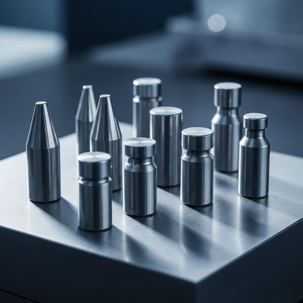
Progresyviųjų mirgalių pilotiniai kaiščiai: liaukitės spėlioję, pradėkite derinti
Pilotinių kaiščių supratimas ir jų svarbus vaidmuo progresyviuose išspaudimo procesuose
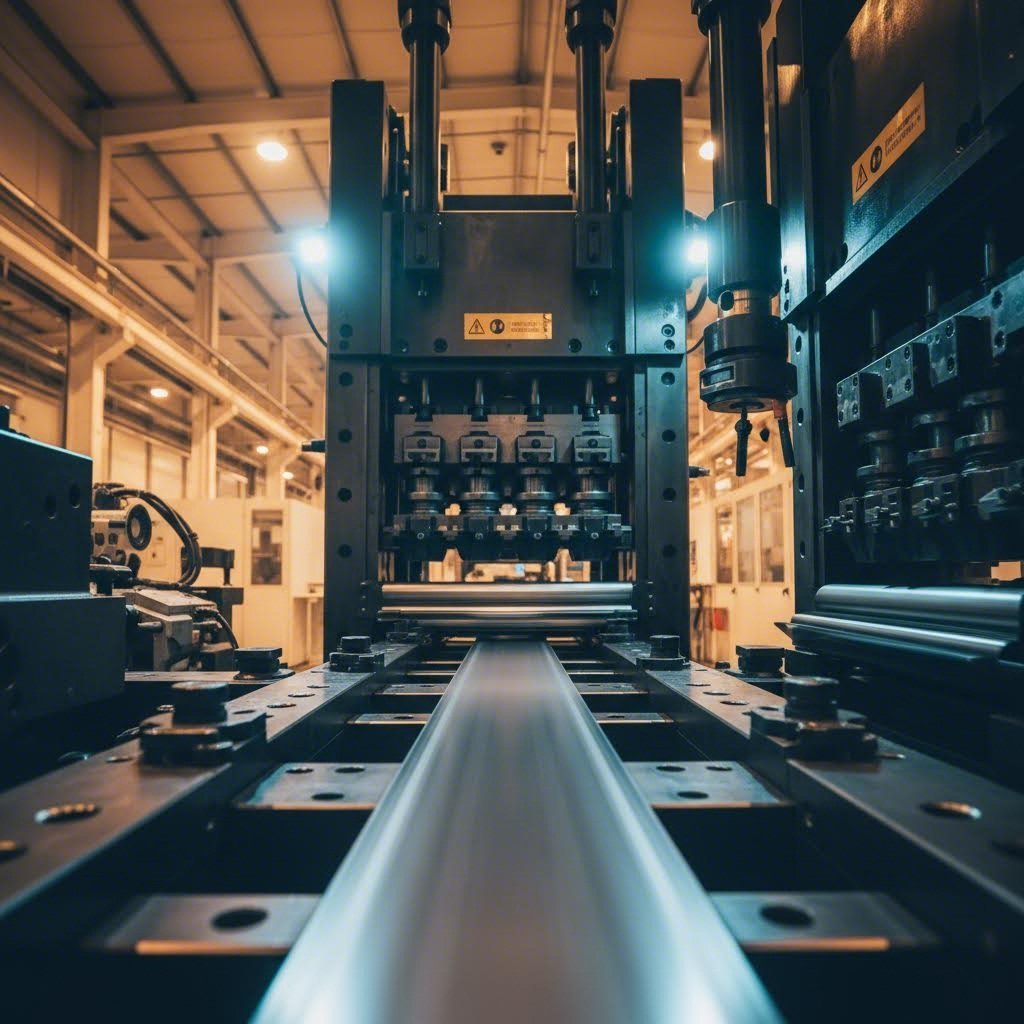
Dirbdami su progresyviu išspaudimu, turite galvoti apie kiekvieną komponentą. Tačiau nedaugelis elementų turi tokį didelį atsakymą už pastovią gaminio kokybę kaip pilotiniai kaiščiai. Šie tikslūs formos komponentai gali atrodyti maži, tačiau jie yra nepripažinti herojai, kurie laiko juostinę medžiagą tiksliai ten, kur ji turi būti – stotis po stoties, ėmimas po ėmimo.
Kas yra pilotiniai kaiščiai ir kodėl jie svarbūs
Pilotiniai kaiščiai yra cilindriniai tikslieji įrankiai kurie kiekvieno presavimo ėmimo metu patenka į iš anksto esančias skylutes juostinėje medžiagoje. Jų pagrindinė funkcija? Užtikrinti, kad juosta būtų idealiai išdėstyta prieš atliekant bet kokius formavimo, išpjovimo ar skverbimo veiksmus. Galvokite apie juos kaip apie savo progresyvaus išspaudimo formos projektavimo lygiavimo tvirtinimo taškus.
Netinkamai veikiant pilotiniams kaištams, jūsų progresyviųjų štampų gaunami gaminiai patirtų kaupiamąsias pozicionavimo klaidas. Kiekviena stotis priklauso nuo ankstesnės tikslumo, sukuriant grandininę reakciją, kurioje net mažos nelygiavimų paklaidos dauginasi į didelės apimties kokybės problemas. Rezultatas? Atmesti gaminiai, pernelyg dideli atliekų kiekiai ir ankstyvas štampos nusidėvėjimas, kuris mažina jūsų pelningumą.
Paaiškinamas registracijos veiksmo principas
Registracijos veiksmas aprašo, kaip pilotiniai kaištai sąveikauja su juosta, kad būtų pasiekta tiksli padėtis. Kai štampa užsidaro, kaištai įeina į pilotines skyles, kurios paprastai išmušamos ankstesnėje stotyje. Ši sąveika priverčia juostą užimti tinkamą vietą dar prieš tai, kai bet koks įrankis palies ruošinį.
Procesas vyksta tam tikra seka:
- Preso stūmoklis leidžiasi, priartindamas viršutinę štampo plokštę prie juostos
- Pilotiniai kaištai susiliečia su atitinkamomis skylėmis dar prieš kitų įrankių sąveiką
- Kaišto su siaurėjančiu arba rutulio formos galu įėjimas tiksliai centruoja juostą
- Pilnas įsijungimas užfiksuoja juostą pozicijoje formavimo operacijai
- Po ėjimo pabaigos, juosta paslenkama į kitą stotį
Šis registravimo veiksmas turi būti nuoseklus tūkstančiams – kartais milijonams – ciklų. Bet koks skirtumas laikui, tarpui ar kaiščio būklei tiesiogiai veikia jūsų gatavus detalių.
Juostos pozicionavimo pagrindai progresyviuose kalibravimo įrankiuose
Tikslus juostos pozicionavimas reiškia ne tik vieną kartą pasiekti teisingą vietą. Tai reiškia taiklią poziciją išlaikyti kiekvienoje kalibravimo įrankio stotyje. Progresyvūs kalibravimo įrankiai dažnai turi nuo keturių iki dvidešimties ar daugiau stočių, kiekviena atlieka specifinę operaciją su juosta.
Net 0,001 colio nesuderinamumas pirmoje stotyje gali stipriai kaupiatисi, kol juosta pasiekia paskutinę stotį, galiausiai sukurdama dalis, kurios visiškai neatitinka specifikacijų.
Keli veiksniai lemia, kiek gerai jūsų pilotiniai kaiščiai išlaiko juostos padėtį:
- Kaiščio skersmens tikslumas: Kaiščio dydžio ir skylės dydžio santykis nulemia, kiek kiekvienas įsiterpimas gali ištaisyti
- Įvedimo geometrija: Koninės arba suapvalintos galai leidžia išlyginti pradinį nesutapimą įsiterpus
- Kaiščio būklė: Nusidėvėję ar pažeisti kaiščiai laikui bėgant praranda centruojančias savybes
- Juostinės medžiagos elgsena: Skirtingos medžiagos skirtingai reaguoja į kaiščių taikomas taisomąsias jėgas
Šių pagrindų supratimas padeda priimti pagrįstus sprendimus, kurie kaiščių tipai geriausiai tiks jūsų konkrečiam progresyvaus štampo taikymui. Teisingas pasirinkimas sumažina atliekų kiekį, pailgina štampos tarnavimo laiką ir užtikrina sklandų gamybos procesą.
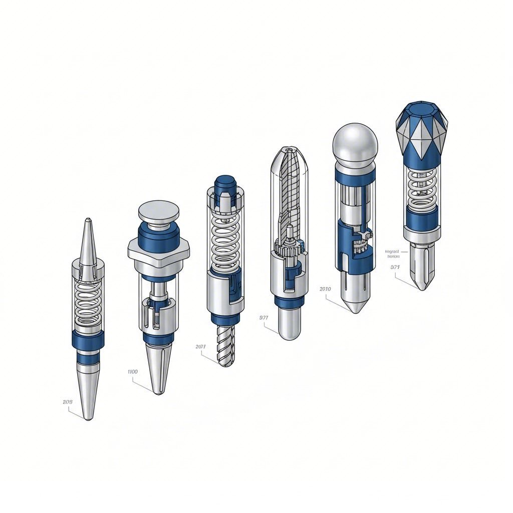
Išsami kaiščių tipų klasifikacija
Dabar, kai suprantate, kodėl svarbūs pilotiniai kaiščiai, panagrinėkime skirtingus tipus, galimus naudoti jūsų progresyviems mirkams. Teisingo pilotinio kaiščio tipo pasirinkimas nėra atspėjimas – tai strateginis sprendimas, priklausantis nuo jūsų specifinių kalibravimo formos detalių, medžiagos charakteristikų ir gamybos reikalavimų. Štai išsamus paaiškinimas, kurio jums reikia.
Tiesioginiai pilotai ir netiesioginiai pilotai
Pagrindinis skirtumas tarp pilotinių kaiščių klasifikacijos priklauso nuo to, kaip jie sąveikauja su juostos medžiaga. Šis skirtumas yra būtinas suprasti visiems, dirbantiems su įvairiais kalibravimo formų tipais.
Tiesioginiai pilotai įeina į angas, kurios atlieka dvigubą funkciją – tai tiek pilotinės angos, tiek funkcionalūs gaminio detalės elementai. Įsivaizduokite laikiklį su tvirtinimo angomis; būtent tos pačios angos veda juostą per formą. Šis metodas veikia gerai, kai jūsų detalės projektavime jau yra tinkamo dydžio angos patogiose vietose.
Privalumai yra aiškūs:
- Nereikia papildomos gręžimo operacijos tik vadovavimui
- Supaprastinta įrankio konstrukcija su mažesniu stotelių skaičiumi
- Sumažintas juostinės medžiagos atliekų kiekis
Netiesioginiai vadovai , kita vertus, naudoja specialiai rezervuotas pilotines skyles, kurios yra skirtos tik registravimo tikslais. Šios skylės paprastai išmušamos šiukšlių zonoje arba nešančiojoje juostoje ir nesimatuoja galutiniame gaminyje. Kai jūsų gaminio geometrija neteikia tinkamų skylių tiesioginiam vadovavimui, netiesioginiai vadovai tampa pagrindiniu sprendimu.
Kodėl pasirinkti netiesioginius vadovus?
- Visiškas kontrolės lygis dėl pilotinės skylės vietos ir dydžio
- Nuoseklus vadovavimas nepriklausomai nuo gaminio geometrijos pokyčių
- Gerokai tinkamesnis taikymams, reikalaujantiems siaurų tolerancijų
- Pilotinės skylės dėvėjimasis neįtakoja gaminio kokybės
Spyruoklės veikiami ir atitraukiami projektavimo sprendimai
Standartiniai kietieji pilotai puikiai veikia daugelyje taikymų, tačiau kas nutinka, kai jūsų įvorės sinchronizavimas ar juostos padavimas reikalauja didesnės lankstumo? Būtent čia pasirodo spyruoklės veikiami ir atitraukiami konstrukciniai sprendimai.
Spyruoklės veikiami pilotai turi vidinį spyruoklės mechanizmą, kuris leidžia pinui atsitraukti esant slėgiui. Kai juosta juda pirmyn tarp smūgių, bet koks nedidelis trukdys verčia pilotą suspausti, o ne pažeisti juostos ar jo paties. Kai preso stūmoklis vėl nusileidžia, spyruoklė grąžina pilotą į visą išorinę padėtį, užtikrindama tinkamą sujungimą.
Vertinsite spyruoklės veikiamus pilotus:
- Dirbant aukšto greičio operacijas, kur juostos laikas yra kritinis
- Dirbant su plonais medžiagomis, linkusiomis deformuotis
- Susiduriant su nedideliais juostos padavimo nenuoseklumais
- Mažinant riziką, kad pilotas sulūžtų diegimo metu
Atrajektami pilotai plėtikite šią koncepciją toliau naudodami pneumatinį arba ekscentrinio valdymo mechanizmus. Vietoj spyruoklinio slėgio šie pilotai aktyviai atsitraukia nuo juostos programuotais taškais presavimo cikle. Šis aktyvus atsitraukimas užtikrina, kad pilotas visiškai būtų pašalintas iki prasidedant juostos tiekimui.
Ištraukiami sistemos puikiai tinka:
- Sudėtingoms progresyvioms mirgėms su ilgais padavimo ilgiais
- Taikymams, reikalaujantiems tikslaus laiko kontrolės
- Didelės apimties gamybai, kur patikimumas yra svarbiausias
- Situacijoms, kai spyruokliniai pilotai negali pakankamai atsitraukti
Kulkos formos ir peties tipo pilotų konfigūracijos
Už pagrindinį mechanizmą einant, jūsų pilotinio kaiščio galinės dalies geometrija radikaliai veikia našumą. Dvi svarbias konfigūracijas verta išnagrinėti atidžiau.
Kulkos formos pilotai turi trapozinį arba apvaliu galu įėjimo tašką, kuris užtikrina automatinį centruotę . Kai juosta šiek tiek pasislenka, įstrižai išpjauta paviršius nukreipia ją į tinkamą padėtį, kai vedlys įeina į skylę. Ši lanksti įvesties konstrukcija sumažina apkrovą tiek vedliui, tiek juostos medžiagai.
Kulkos formos galvutės dizainas ypač naudingas, kai:
- Pradinė juostos pozicija šiek tiek skiriasi tarp eilių
- Dirbant su medžiagomis, kurios naudojasi palaipsniui vykstančiu užfiksavimu
- Kompensuojant nedidelius šiluminio plėtimosi efektus
- Sumažinant smūginį poveikį aukšto greičio taikymo srityse
Peilio tipo vedliai turi pakopinį skersmenį, kuris užtikrina tikslų gylį. Didesnė peties dalis sustoja prieš die paviršių arba žvakidės plokštę, užtikrindama, kad vedlys kaskart įsiskverbtų tiksliai reikiamu gyliu. Ši savybė prevencijai nuo per didelio įsibrovimo, kuris galėtų pažeisti plonas medžiagas ar sukelti juostos iškraipymą.
Peilio tipo vedliai būtini, kai:
- Nuolatinis įsiskverbimo gylis yra būtinas tinkamai registracijai
- Dirbant su kintamu juostų storiu skirtingose gamybos serijose
- Įprėžio projektavimas reikalauja teigiamo gylio apribojimo
- Delikatesnių išspaudimo įprėžių komponentų apsauga nuo atsitiktinio pažeidimo
Visų pilotinių kaiščių tipų palyginimas
Apžvelgus visus šešis tipus, pateikiama išsami atskaitos lentelė, kuri padės Jums pasirinkti:
| Tipas | Mechanas | Įėjimo būdas | Tipinės taikymo sritys | Pagrindiniai pranašumai |
|---|---|---|---|---|
| Tiesioginis pilotinis kaištis | Standžiai fiksuota pozicija | Standartinis arba kulkos formos galvutė | Detalės su tinkamomis esamomis skylėmis; paprastesnių įprėžių konstrukcijos | Sumažintos stotys; žemesnės įrankių kainos; paprastesnis dizainas |
| Netiesioginis pilotas | Standžiai fiksuota pozicija | Standartinis arba kulkos formos galvutė | Tikslūs darbai; sudėtingos detalių geometrijos | Visiškas kontrolė pilotų vietose; nuosekli registracija |
| Su lanksteliu | Vidinė spyruoklės suspaudimo sistema | Įprastai su rutuliniu galu | Greitas štampavimas; plonos medžiagos; kintamos padavimo sąlygos | Sumažintas lūžimo pavojus; prisitaiko prie laiko skirtumų |
| Sutrinamas | Pneumatiniu arba mechanizmu valdomas | Galimi įvairūs variantai | Ilgios padavimo ilgis; sudėtingi mirai; didelės apimties gamyba | Teigiama atbulinė eiga; tikslus laiko reguliavimas; maksimalus patikimumas |
| Kulkos formos | Geometrijos pagrįsta (gali būti standi arba su spyruokle) | Taperuotas / suapvalintas įėjimas | Taikymai, reikalaujantys automatinio centavimo; kintama juostelės pozicija | Automatinio centavimo galimybė; sumažintas įtempis įėjime; lanksti sandūra |
| Šokolas | Laipsniško skersmens konstrukcija | Įvairūs antgalio variantai | Gylį reikalaujantys taikymai; kintamas medžiagos storis | Tiksli gylis kontrolė; neleidžia pernelyg įterpti; apsaugo plonas medžiagas |
Turėkite omenyje, kad šios kategorijos nėra viena kitai išskiriančios. Galite nurodyti netiesioginį, spyruoklę turintį pilotą su rutulio formos įėjimu ir peties gylis kontrole – derinant savybes taip, kad jos atitiktų jūsų tikslus reikalavimus. Svarbiausia suprasti, ką siūlo kiekviena charakteristika, kad galėtumėte sukurti tinkamą derinį savo žymėjimo mirų komponentams.
Turėdami šią klasifikavimo sistemą, jūs esate pasirengę išsamiau ištirti, kaip konkrečios taikymo situacijos daro įtaką pasirinkimui tarp tiesioginių ir netiesioginių pilotų.
Tiesioginiai ir netiesioginiai pilotai taikyme
Jūs jau matėte klasifikacijos pateikimą – dabar pereikime prie praktikos. Tiesioginių ir netiesioginių pilotų pasirinkimas nėra mėgstamiausio pasirinkimas. Svarbu pritaikyti pilotų tipą konkrečioms gamybos sąlygoms. Spustelėjimo metu sprendimas priklauso nuo medžiagos storio, leistinų nuokrypių, juostos padavimo būdo bei fizinės spaudžiamo gaminio savybių. Išnagrinėkime, kada kiekvienas variantas tinka jūsų progresyviems išspaudimo įrankiams.
Kada pasirinkti tiesioginius pilotus
Tiesioginiai pilotai puikiai tinka ten, kur svarbiausia paprastumas ir efektyvumas. Kadangi jie naudoja skyles, kurios tampa galutinio gaminio dalimi, jūs pašalinat visą vertimo operaciją iš įrankio progresyvioje suvirinimo linijoje. Tačiau šis patogumas turi kompromisus, kuriuos turite suprasti.
Tiesioginiai pilotai veikia geriausiai, kai jūsų taikymas atitinka šiuos kriterijus:
- Storesnės medžiagos (0,060 colių ir storesnės): Storesnio kalibro ruošiniai užtikrina reikiamą standumą tiesioginiam pilotavimui be iškraipymų jungiantis
- Didesnių pirminių skylių skersmenys: Skylių, didesnių nei 0,125 colio, atveju suteikiamas palankesnis įėjimas ir sumažinamos tikslumo reikalavimai pirminiams kaiščiams
- Vidutiniai tolerancijos reikalavimai: Kai jūsų galutinio gaminio specifikacijos leidžia ±0,005 colio ar didesnį nuokrypį, tiesioginiai pilotai paprastai užtikrina priimtinus rezultatus
- Žemesni gamybos apimtys: Supaprastinta formos konstrukcija pasiteisina tada, kai negaminami milijonai detalių
- Detalių konstrukcijos su patogiai esančiomis skylėmis: Jei jūsų funkcionaliosios skylės atsitiktinai yra idealiuose pilotavimo vietose, kodėl pridėti nereikalingo sudėtingumo?
Kas blogai? Jūsų detalės geometrija nulemia pilotų vietų pasirinkimą. Jei tos funkcionaliosios skylės nėra optimaliai padėtos juostos valdymui, registruojant tikslumą aukojate vieną stotį. Daugeliui progresyvių kalibravimo formų šis kompromisas nevertas tokios kainos.
Netiesioginių pilotų taikymas ir privalumai
Netiesioginiai pilotai suteikia visišką kontrolę virš registravimo proceso. Skirdami skyles specialiai pilotavimui – paprastai nešančioje juostoje arba atliekų skelete – galite laisvai optimizuoti jų išdėstymą, nesirūpindami dėl detalių geometrijos apribojimais.
Laikykite netiesioginius pilotus būtinais susidūrus su šiais atvejais:
- Plonos medžiagos (mažiau nei 0,030 colio): Lengvos kilmės ruošiniai reikalauja tikslaus, nuoseklaus fiksavimo, kurį užtikrina specialiai skirtos pilotinės skylės
- Griežti tolerancijų reikalavimai (±0,002 colio ar mažiau): Kai svarbiausias tikslumas, negalima palikti pilotinių skylių vietos pasirinkimą detalių konstrukcijos atsitiktinumui
- Didelio greičio operacijos (daugiau nei 400 ėmimų per minutę): Greitesnė gamyba sustiprina bet kokį netikslumą padėtyje – netiesioginiai pilotai išlaiko tikslumą dideliu greičiu
- Sudėtingos detalių geometrijos: Kai funkcionalios skylės nesutampa su optimaliomis pilotavimo pozicijomis, netiesioginiai pilotai išsprendžia šią problemą
- Daugiapoziciniai kalibriniai įrankiai ilgai juostos kelionei: Daugiau stotijų reiškia daugiau galimybių kaupiamajam klaidų kiekiui – specialūs pilotiniai skylės sumažina poslinkį
Taip, jūs pridedate gręžimo operaciją ir sunaudojate šiek tiek daugiau medžiagos. Tačiau lyginant su dideliais tiražais reikalaujančiais aukštos kokybės išspaudimo komponentais, investicija į netiesioginį pilotavimą atsipirks mažesniu broku ir rečiais mirgalio reguliavimais.
Medžiagai specifinių pilotinių elementų parinkimo aspektai
Jūsų juostos medžiaga nesėdi ten tiesiogiai – ji reaguoja į pilotinių elementų sąveikos jėgas būdu, kuris turėtų paveikti jūsų pasirinkimą. Skirtingos metalo rūšys elgiasi skirtingai, o šių savybių nepaisymas veda prie ankstyvo nusidėvėjimo, juostos pažeidimų ar nevienodo tvirtinimo.
Pliena (minkštoji, HSLA ir nerūdijanti): Dėl plieno standumo jis paprastai gerai tinka tiek tiesioginiam, tiek netiesioginiam pilotavimui. Tačiau kietesnės rūšys, tokios kaip nerūdijantis plienas, sukuria labiau abrazyvias sąlygas pilotinių paviršių atžvilgiu. Aukštos stiprybės plienui apsvarstykite netiesioginius pilotinius elementus su karbido antgaliais, kad išlaikytumėte padidėjusius nusidėvėjimo reikalavimus.
Aliuminis: Minkšti aliuminio lydiniai turi linkį rautis prie vadovaujančių kaiščių paviršių, ypač dėl didelio greičio sukamomis operacijomis generuojamos šilumos. Netiesioginiai kaiščiai leidžia jums talpinti vadovaujančias skylutes vietose, kur nedidelis paviršiaus pažeidimas neįtakoja detalės kokybės. Poliruoti arba dengti vadovaujantys kaiščiai sumažina rautimosi linkį.
Varis ir variniai lydiniai: Šios medžiagos pasižymi geru formavimu, tačiau ilgainiui gali palikti nuosėdas ant vadovaujančių paviršių. Šioje vietoje gerai veikia spyruokliniai netiesioginiai kaiščiai, nes jie sumažina įsijungimo apkrovą ir pratęsia jūsų išspaudimo detalių valymo intervalus.
Dengtos ir preliminariai apdorotos medžiagos: Cinkuoti, dažyti arba plėvele apsaugoti juostiniai ruošiniai reikalauja atsargaus kaiščių parinkimo. Tiesioginiai kaiščiai, patenkantys į funkcines skylutes, gali pažeisti dangą matomose detalės paviršiaus dalyse. Netiesioginiai kaiščiai šiukšlių zonose visiškai išvengia šios problemos, apsaugodami jūsų galutinį išvaizdą.
Padavimo būdo įtaka kaiščių veikimui
Tai, kaip juosta juda į die, paveikia tai, kuris pilotas veikia geriausiai. Du pagrindiniai maitinimo scenarijai – rankinis ir mechaninis – sukuria skirtingus iššūkius.
Rankinio maitinimo operacijos (permaitinimo tendencija): Kai operatoriai rankiniu būdu stumia juostą, dažnai šiek tiek perdaug ją pastumia. Juosta juda už idealios pozicijos, todėl pilotams reikia ją traukti atgal jungimosi metu. Šiuo atveju puikiai tinka netiesioginiai kulkos formos galiniai pilotai, kurie užtikrina centruojamąją jėgą, reikalingą nuolat taisyti permaitinimo sąlygas.
Mechaninio maitinimo operacijos (nepakankamo maitinimo tendencija): Automatiniai maitintuvai kartais nepakankamai padeda juostą, dėl ko ji nepasiekia tikslinės pozicijos. Pilotams reikia stumti juostą į priekį įvedimo metu. Tiesioginiai pilotai storesniuose medžiagose tai atlieka gerai, tačiau plonoms medžiagoms naudingi spyruokliniai netiesioginiai pilotai, kurie prisitaiko prie nedidelių laiko skirtumų, nesugadinant juostos.
Suprantant jūsų specifinį maitinimo elgesį – ir tai, kaip jis sąveikauja su medžiaga bei tarpinių reikalavimų tikslumu – galima pasirinkti tokį pilotinio įrenginio konfigūravimą, kuris užtikrins progresyvių išspaudimo formų veikimą maksimalia efektyvumo riba. Kai šie taikymo scenarijai aiškūs, galite vertinti, kaip pilotinių kaištų medžiagos ir kietumo charakteristikos veikia ilgalaikį darbą.
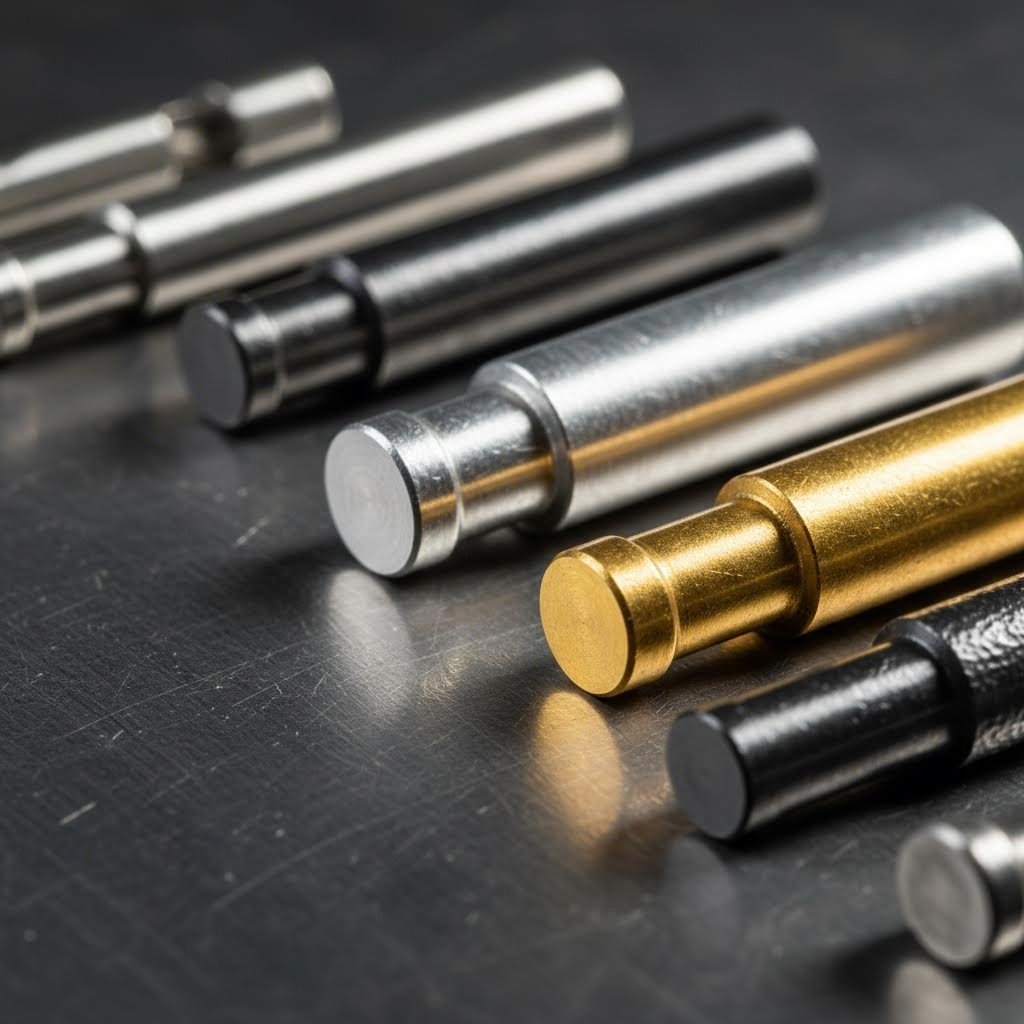
Pilotinių kaištų medžiagos ir kietumo reikalavimai
Teisingo pilotinio kaišto tipo parinkimas yra tik pusė lygties. Medžiaga, iš kurios pagaminti kaištai, nulemia jų tarnavimo laiką, atsparumą dilimui bei gebėjimą atlaikyti specifinius išspaudimo įrankių taikymo reikalavimus. Panagrinėkime medžiagų pasirinkimo variantus, kurie padeda jūsų progresyvioms formoms veikti maksimaliu našumu.
Įrankių plienų pasirinkimas ir kietumo charakteristikos
Įrankių plienai iki šiol lieka pagrindiniais pilotinių kaištų gamybos medžiagų tipais. Rinkoje dominuoja trys rūšys, kiekviena siūlanti skirtingas privalumus skirtingoms gamybos situacijoms.
D2 Įrankių plienas: Šis aukšto anglies ir chromo plienas užtikrina puikų nusidėvėjimo atsparumą ir matmeninę stabilumą. Turėdamas įprastą kietumą nuo 58 iki 62 HRC, D2 plienas efektyviai susitvarko su abrazyviškais medžiagomis ir didelės apimties serijomis. D2 ypač tinka:
- Išspaudimo formų smeigiams, dirbantiems prieš sunkesnes juostines medžiagas
- Taikymams, kuriems reikia ilgesnių laikotarpių tarp keitimų
- Situacijoms, kai briaunos išlaikymas yra svarbus pastoviam sukibimui
A2 įrankinė plienas: Siūlydamas pusiausvyrą tarp atsparumo smūgiams ir nusidėvėjimo atsparumo, A2 paprastai pasiekia 57–62 HRC kietumą. Jo oru kietinamos savybės mažina iškraipymą šiluminei apdorojant, todėl jis yra idealus, kai kritinė reikšmė teikiama matmeninei tikslumui. Pasirinkite A2, kai:
- Jūsų pilotai turi sugerti tam tikrą smūgį, nesuskeldėdami
- Formų konstrukcijos reikalauja tikslaus, stabilaus matmens po kietinimo
- Kainos apsvarstymai palankesni universaliai vidurinio lygio parinkčiai
M2 aukštakokyiškasis plienas: Kai temperatūra tampa svarbiu veiksniu, M2 pranašesnis už įprastines įrankių plieno rūšis. Iki 60–65 HRC sukietintas volframo-molibdeno lydinys išlaiko savo kietumą aukštoje temperatūroje, siekiančioje iki 1000 °F. M2 puikiai tinka:
- Aukštos greičio spaustuvų dalių, kurios sukuria didelį trinties šilumą
- Tolydi gamyba be aušinimo pertraukų
- Taikymai, kai raudonas kietumas (karštas kietumas) neleidžia suminkštėti
Kai karpiniai vedliai yra ekonomiškai pagrįsti
Iliuminiai karpiniai ir karpiniu galvutėmis vedliai reiškia ženklų šuolį tiek našumo, tiek kainos atžvilgiu. Veikdami 80–92 HRA (maždaug atitinka 68–75 HRC), volframo karbidai užtikrina dilimo atsparumą, kurio įrankių plienai paprasčiausiai negali pasiekti.
Tačiau kada ši brangesnė investicija atsipirks? Apsvarstykite karpinius vedlius, kai jūsų gamyba atitinka šiuos kriterijus:
- Gamybos apimtys viršija 500 000 detalių: Ilgtesnis įrankių tarnavimo laikas padalina didesnę pradinę kainą į daugiau detalių, sumažindamas įrankių sąnaudas vienai daliai
- Juostos medžiaga yra labai abrazyvinė: Nerūdijantis plienas, silicio plienas ir darbo sukietėję lydiniai greitai susidėvi įrankių plieno žygmens – kietmargis atsparus šiam nusidėvėjimui
- Pristabdymo išlaidos yra didelės: Jei stabdant jūsų presavimo mašiną dėl žygmenų keitimo kyla brangios gamybos pertraukos, kietmargio ilgaamžiškumas užtikrina tikras sutaupymus
- Nuoseklumo reikalavimai yra griežti: Kietmargis ilgiau išlaiko savo matmenis nei įrankių plienas, todėl ilgalaikėse serijose tiksliai išlaikomas tinkamas pozicionavimas
Koks kompromisas? Dėl kietmargio trapumo jis ne taip gerai toleruoja smūgius ar netinkamą išdėstymą kaip įrankių plienas. Naudojant kietmargius žygmenis, tinkamas įrankių montavimas ir išlyginimas tampa dar svarbesni
Paklotų technologijos ilgesniam žygmenų tarnavimui
Kartais nereikia keisti viso žygmenų komplekto – paviršiaus danga gali žymiai pailginti tradicinių įrankių plieno kaiščių tarnavimo laiką. Šiuolaikinės dangos technologijos siūlo tiksliniai sprendimus specifinėms nusidėvėjimo problemoms
Titano nitridas (TiN): Šis aukso spalvos denginys padidina paviršiaus kietumą iki maždaug 2300 HV (Vikerso) ir sumažina trintį juostos įsikibimo metu. TiN puikiai tinka visuotinio pobūdžio taikymui ir užtikrina pastebimą įrankių tarnavimo laiko pailgėjimą palyginti nedidelėmis sąnaudomis.
Titano karbonitridas (TiCN): Kietesnis nei TiN – apie 3000 HV, TiCN puikiai veikia prieš abrazyvines medžiagas. Pagerinta slystamumas taip pat sumažina medžiagos įbrėžimus štampuojant aliuminio ar vario lydinius.
Dia-mo panaši anglis (DLC): Didžiausiam dilimui atsparumui ir žemiausiems trinties koeficientams pasiekti DLC denginiai pasiekia daugiau nei 5000 HV. Nors jie yra brangesni, DLC žymiai pailgina vedančiųjų kaiščių tarnavimo laiką reikalaujamose sąlygose ir beveik visiškai pašalina medžiagos prilipimą prie kaiščio paviršiaus.
Medžiagų parinkimo palyginimo gidas
Naudokite šį vadovą renkantis vedančiųjų kaiščių medžiagas pagal savo štampavimo įrangos reikalavimus:
| Medžiagos tipas | Tipinė tvirtumo riba | Geriausi taikymo atvejai | Santykinė kaina | Numatytas įrankių tarnavimo laikas |
|---|---|---|---|---|
| A2 Įrankių plienas | 57-62 HRC | Visuotinio pobūdžio; vidutiniai apimtys; smūgiams linkusios konfigūracijos | Žemi | Vidurkis |
| D2 įrankių plienas | 58-62 HRC | Abrazyvinės medžiagos; didesnės apimtys; pratęstas atsparumas dilimui | Žema-vidutinė | 1,5–2x bazinis |
| M2 aukštos kokybės plienas | 60-65 HRC | Aukštos greičio operacijos; padidėjusios temperatūros; karštas žymėjimas | Vidmenis | 2–3 kartus daugiau nei bazinis |
| Įrankių plienas + TiN danga | Bazė + 2300 HV paviršius | Trinties sumažinimas; vidutinė nusidėvėjimo patobulinimas; kainos efektyvus patobulinimas | Vidmenis | 2–4 kartus daugiau nei bazinis |
| Įrankių plienas + TiCN danga | Bazė + 3000 HV paviršius | Abrazyvinės juostelės; aliuminio/vario įbrėžimų prevencija | Vidutinis-Aukštas | 3–5 kartų bazinį |
| Tvarus karbidas | 80–92 HRA | Labai dideli kiekiai; itin abrazyvios medžiagos; maksimalus nuoseklumas | Aukšto | 5–10 kartų bazinį |
| Įrankių plienas + DLC danga | Pagrindas + daugiau kaip 5000 HV paviršius | Ultražemas trinties koeficientas; medžiagos prikibimo pašalinimas; aukščiausios kokybės taikymai | Aukšto | 5–8 kartų bazinį |
Karšto formavimo temperatūros apsvarstymai
Kai jūsų progresyvioji mira veikia aukštesnėse temperatūrose – ar tai būtų dėl karštai formuojamo juostinio medžiagalo, ar dėl trinties šilumos kaupimosi – medžiagų atranka tampa dar svarbesnė.
Standartiniai įrankių plienai, tokie kaip D2 ir A2, pradeda prarasti kietumą aukštesnėje nei 400 °F temperatūroje. Karšto štampavimo taikymuose, kai juostos temperatūra gali pasiekti 600 °F arba dar aukštesnę, šis minkštėjimas žymiai pagreitina dėvėjimąsi. M2 sparčiajam plienui būdinga darbinė kietumas iki maždaug 1000 °F, todėl jis yra pageidaujamas įrankių plienas terminiams iššūkiams.
Ekstremalioms temperatūroms taikyti apsvarstykite šias strategijas:
- Nurodykite M2 arba lygiavertį sparčiąjį plieną kaip bazinę medžiagą
- Pridėkite šilumai atsparių dangų, tokių kaip AlTiN, kurie išlaiko vientisumą aukščiau nei 1400 °F
- Įterpkite aušinimo kanalus arba orinio srauto sistemas, kad sumažintumėte vedančiųjų dalių veikimo temperatūrą
- Įvertinkite kietmases, kurios išlaiko kietumą platesniame temperatūrų diapazone nei įrankių plienai
Medžiagų savybių sąveikos su gamybos aplinka supratimas užtikrina, kad Jūsų pilotinės kaiščiai parodytų nuoseklų našumą visą jų tarnavimo trukmę. Kai medžiaga parinkta, kitas svarbus dalykas – kaip šie kaiščiai bus pritvirtinti ir koks bus jų dydis, kad būtų pasiekta optimali juostos fiksacija.
Pilotinių kaiščių matmenų tolerancijos ir tvirtinimo būdai
Jūs pasirinkote tinkamą pilotinio kaiščio tipą ir medžiagą – tačiau tai, kaip šie tikslūs kaiščiai yra sumontuoti ir koks jų dydis, lemia, ar jie iš tiesų veiks numatytu būdu. Netinkamas montavimas ar neteisingi tarpai pakenkia net geriausiems komponentų pasirinkimams. Panagrinėkime tvirtinimo būdus, matmenų skaičiavimus ir pozicionavimo strategijas, kurios užtikrina tikslų Jūsų presformos rinkinio veikimą.
Presuojami prieš sriegiuotus pilotinius kaiščius
Tai, kaip pilotiniai kaiščiai prijungiami prie įrankio padėklo ar laikiklio plokštės, veikia techninės priežiūros greitį, lygiavimą ir bendrą patikimumą. Dvi pagrindinės fiksavimo metodikos dominuoja įrankių konstrukcijoje.
Presinis montavimas remiasi tarpiniu pasirinkimu tarp vedančiosios galvutės ir jos tvirtinimo skylės. Galvutės skersmuo yra šiek tiek didesnis nei skylės, todėl reikia pastangų, kad įdėti kaištį. Įdiegus, trintis viską laiko vietoje.
Presuojamas tvirtinimas veikia gerai, kai:
- Gamybos ciklai yra pakankamai ilgi, kad pateisintų paruošimo laiką
- Tikslumas derinime yra kritiškai svarbus – nėra tarpelio, o tai reiškia, kad nėra judėjimo
- Eksploatacijos temperatūros lieka stabilios (šiluminis plėtimasis gali atleisti pasirinkimą)
- Keitimo dažnumas yra žemas, mažinant poreikį greitiems keitimams
Koks neigiamas aspektas? Presuotų vedančiųjų elementų nuėmimui reikia specializuotų įrankių ir kartojant procedūrą kyla pavojus pažeisti tvirtinimo skylę. Laikui bėgant, skylių dilimas gali atleisti anksčiau patikimą pasirinkimą.
Sriegiuotas tvirtinimas naudoja varžtą arba sriegį, kad pritvirtintų pilotą į išdrožtą kišenę. Šis metodas užtikrina greitesnius keitimus ir paprastesnę pakeitimą planuotų techninės priežiūros metu.
Pasirinkite sriegiuotą tvirtinimą, kai:
- Dėl dilimo ar gamybos mišinio dažnai tikimasi keisti pilotus
- Greito keitimo funkcija sumažina brangų prastovų laiką jūsų progresyviajame išspaudime
- Keli skirtingo dydžio pilotai gali būti naudojami tame pačiame įrenginyje keičiant įrankius
- Svarbu, kad būtų galima aptarnauti vietoje – standartiniais įrankiais galima atlikti pakeitimą
Kompromisas yra tai, kad vibracijos metu gali atsiveržti. Gnybtiniai jungikliai ar kontroveržės padeda išlaikyti patikimumą ilgoms gamybos serijoms
Piloto ir angos tarpų apskaičiavimas
Tarpas tarp jūsų piloto skersmens ir juostos pilotinei angai turi būti tinkamas, kad užtikrinti teisingą pozicijavimą. Per mažas tarpas gali pažeisti juostą ar sulaužyti pilotą. Per didelis tarpas sumažina pozicijavimo tikslumą
Laikykitės šio žingsnis po žingsnio proceso, norėdami nustatyti tinkamą piloto dydį:
- 1 žingsnis: Nustatykite savo pilotinės angos skersmenį Tai paprastai yra vardinis išspaudžiamos angos dydis atėmus numatomą kirpimo operacijos sukeltą griovelį ar iškraipymą
- 2 žingsnis: Nustatykite reikiamą registravimo tikslumą. Tikslesni detalės tarpai reikalauja mažesnių tarpų tarp vadovo ir skylės.
- 3 žingsnis: Apskaičiuokite vadovo skersmenį. Pradėkite nuo vadovaujančios skylės skersmens ir atimkite bendrą diametrinį tarpą. Tiksliajam darbui dažnai naudojamas pradinis taškas yra 0,001–0,002 colio iš vienos pusės (0,002–0,004 colio bendras diametrinis tarpas).
- 4 žingsnis: Pataisykite pagal medžiagos storį. Plonesnėms medžiagoms reikia šiek tiek didesnių tarpų, kad būtų išvengta juostos iškraipymo jungiant. Medžiagoms, kurios yra storesnės nei 0,020 colio, padidinkite tarpą apie 10–15 %.
- 5 žingsnis: Įvertinkite kulkos formos įvedimą. Jei naudojate trapiai bespalį vadovą, tiesiosios dalies skersmuo turėtų atitikti apskaičiuotą tarpą – trapioji dalis suteikia papildomą leistinąją įvedimo erdvę.
- 6 žingsnis: Patikrinkite šilumines sąlygas. Aukšto greičio operacijose, kuriose susidaro šiluma, pridėkite papildomą 0,0005–0,001 colio tarpą, kad kompensuotumėte vadovo išsiplėtimą.
Pavyzdžiui, jei jūsų orientacinė skylė yra 0,250 colio ir reikia tikslaus atitikimo 0,030 colio storio plieno detalėje, galite nurodyti orientacinio kaiščio skersmenį 0,247 colio – tai suteikia po 0,0015 colio tarpelį kiekvienai pusei. Plonesnis 0,015 colio aliuminis gali reikalauti 0,246 colio, kad būtų išvengta juostos lenkimo įsijungimo metu.
Greito keitimo sistemos didelės apimties gamybai
Kai jūsų progresyvioji išspaudimo mašina apdoroja kelis detalių numerius arba reikalauja minimalios prastovos trukmės, greito keitimo orientavimo sistemos greitai atsipirks. Šios sistemos sujungia presinių konstrukcijų tikslų derinimą su sriegiu tvirtinamų sistemų aptarnavimo patogumu.
Šiuolaikinės greito keitimo konfigūracijos paprastai turi šias savybes:
- Tikslieji įmovos guoliai: Įkaitintos įvorės, presuojamos į išspaudimo kalibrą, leidžia naudoti keičiamus orientacinius kaiščius su kontroliuojamu tarpeliu
- Spiralinis arba baioneto tipo tvirtinimas: Ketvirties posūkio mechanizmai, kurie užtikrina kaiščių fiksavimą be sriegio ar presavimo
- Modulinės patrono konstrukcijos: Visiškai sumontuoti pilotiniai mazgai, kurie įstatomi ir užrakinami, pašalinant atskirų detalių tvarkymą
- Raktinė padėtis: Apsukimo prevencijos funkcijos, užtikrinančios, kad pilotai kiekvieną kartą būtų teisingai orientuojami montavimo metu
Greitai keičiamų formos įrankių komponentų įsigijimas yra naudingas, kai dėl nusidėvėjimo, pažeidimų ar gamybos perėjimų tenka dažnai keisti pilotus. Apskaičiuokite dabartinę prastovos kainą vienam keitimui, padauginkite iš metinio keitimų dažnumo ir palyginkite su sistemos kaina. Didelės apimties štampavimo formų surinkimo operacijoms tokia matematika dažniausiai rodo, kad greito keitimo sistema atsipirks jau pirmais metais.
Padavimo ilgis ir pilotinių elementų pozicionavimo reikalavimai
Tai, kur pilotus talpinate palei juostos judėjimo kelią, yra taip pat svarbu kaip ir tai, kaip juos sumontuojate. Santykis tarp padavimo ilgio ir pilotinių elementų vietos tiesiogiai veikia registravimo tikslumą ir juostos stabilumą
Atsižvelkite į šiuos pozicionavimo principus:
- Talpinkite pilotus prieš svarbiausias operacijas: Registravimo taškus įrengti prieš stotis, turinčias griežčiausius tolerancijų reikalavimus
- Atsižvelkite į juostos ištempimą: Ilgesni padavimo ilgiai leidžia didesnį kaupiamąjį ištempimą – papildomi pilotiniai stovai kompensuoja šį poslinkį
- Subalansuokite pilotinių apkrovą: Paskirstykite pilotus tolygiai per visą juostos plotį, kad būtų išvengta sukryžavimo arba pasukimo metu jungiant
- Derinkitės su kėlimo padėtimis: Užtikrinkite, kad kėlimai netrukdytų pilotų veikimui ar nesukeltų juostos svyravimo šalia pilotų vietų
Formoms, kurių padavimo ilgis viršija 2 colius, rekomenduojama naudoti pilotus kas antrame stovelyje kaip minimumas. Kai padavimo ilgis viršija 4 colius, dažnai naudinga naudoti pilotus kiekviename stovelyje, kad užtikrintumėte nuoseklią registraciją visą juostos judėjimo trajektoriją. Galutinę pilotų pozicijų parinkimą turėtų nustatyti jūsų specifinė tikslumo analizė.
Nustačius tvirtinimo būdus ir matmenų tarpus, svarbu suprasti, kas nutinka, kai kyla problemų – ir kaip diagnozuoti pilotinių kaištų problemas dar iki jų iškilimo, kad nebūtų sutrikdyta gamyba.
Pilotinių kaištų gedimų rūšys ir gedimų šalinimas
Net geriausias pilotinio kaiščio parinkimas ir montavimas negali užkirsti kelio visoms problemoms. Gamybos aplinkos yra reikalaujančios, o komponentai galiausiai susidėvi. Mažos nepatogumų ir didelės gamybos katastrofos skirtumą dažnai lemia tai, kaip greitai nustatysite, kas vyksta ne taip – ir kodėl. Suprantant progresyvaus išspaudimo mirklių problemas, susijusias su pilotiniais kaiščiais, galima anksti pastebėti problemas, atlikti tikslinį išspaudimo formos remontą ir įgyvendinti veiksmingas formos techninės priežiūros klaidų šalinimo strategijas.
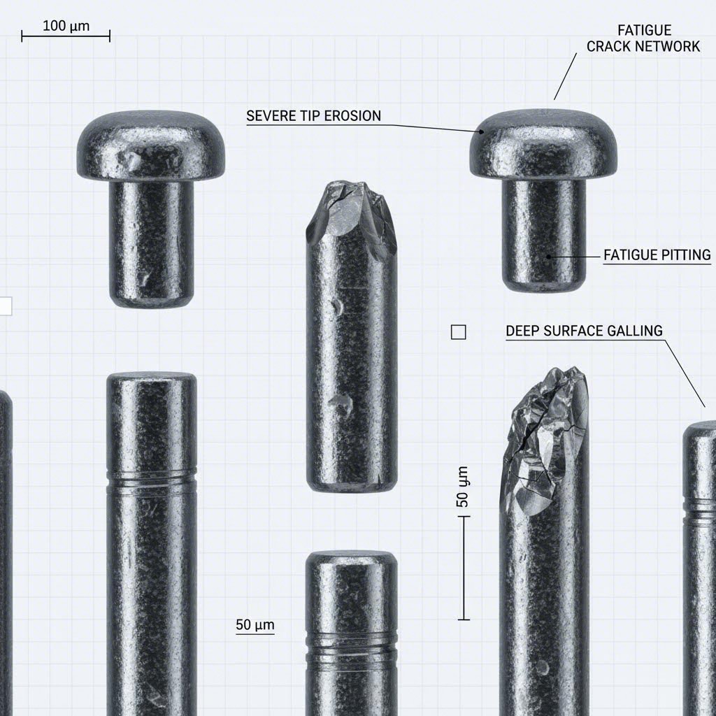
Dažni pilotinių kaiščių susidėvėjimo modeliai ir priežastys
Pilotinių kaiščių susidėvėjimas vyksta neatsitiktinai. Konkrečios susidėvėjimo schemos tiksliai parodo, kas sukelia nusidėvėjimą – jei žinote, ko ieškoti.
Vienodas galo susidėvėjimas: Kai jūsų įvedimo galinukas rodo tolygų susidėvėjimą viso įvedimo paviršiaus apimtimi, tai reiškia normalų eksploatacinį susidėvėjimą. Adatinis galinukas tinkamai atlieka savo funkciją, o juostos medžiaga tiesiog laikui bėgant trina paviršių. Šis modelis rodo tinkamą išdėstymą ir tarpus. Jūsų veiksmai? Planuokite keitimą pagal išmatuotą susidėvėjimo greitį, kol tikslumas nenukentėjo.
Vienpusis nusidėvėjimas: Asimetriškas susidėvėjimas, koncentruotas vienoje galinuko pusėje, rodo nuolatinį šoninį apkrovimą. Juosta kiekvienu ėmimu patenka išcentriniu būdu, todėl galinukui teks nuolat taisyti tą pačią kryptį. Pagrindinės priežastys yra:
- Maitintojo netinkamas išlyginimas, dėl kurio juosta pastoviai stumiama į vieną pusę
- Vadovo bėgių susidėvėjimas, leidžiantis juostai šokinėti šoninėmis kryptimis
- Įrėžo padėklo arba išstūmimo plokštės netinkamas išlyginimas
- Šiluminis plėtimasis, sukuriantis nelygius sąlygas per visą įrėžą
Užstrigimas ir medžiagos prilipimas: Kai pastebite, kad juostelės medžiaga prilipo prie zondo paviršiaus, trintis ir šiluma suvirina daleles prie jūsų zondo. Aliuminis, varis ir dengti medžiagai ypač būdingas toks zondo nusidėvėjimo tipas. Išspręskite tai pagerindami tepimą, naudodami padengtus zondus arba poliruotus paviršius, kurie atsparūs prilipimui.
Padidėjęs nusidėvėjimo tempas: Jei zondai nusidėvi greičiau nei tikėtasi, atsižvelgiant į gamybos apimtį ir medžiagos tipą, tikriausiai susiduriama su netinkamu medžiagų deriniu. Arba jūsų zondo kietumas nepakankamas dėl juostelės medžiagos abrazyvumo, arba dirbama pernelyg dideliu greičiu, kuris sukuria šilumą, minkštinančią zondo paviršių. Apsvarstykite galimybę pereiti prie kietesnio įrankinio plieno, kietlyčių arba pridėti nusidėvėjimui atsparių dangų.
Lūžių ir netinkamo išdėstymo problemų diagnostika
Zondo lūžimas nedelsiant sustabdo gamybą. Supratę, kodėl tai įvyko, galima išvengti pakartotinių gedimų.
Galo lūžimas (skilimas): Kai suskyla ar sulūžta tik zondo priekinis kraštas, įvedimo kampas sąlygomis yra pernelyg agresyvus. Priežastys gali būti:
- Nepakankamas tarpas tarp pilotinio elemento ir skylės – kaišis įvaromas per jėgą
- Juostos padavimo sinchronizavimo problemos, dėl kurių pilotinis elementas pataiko į vientisą medžiagą, o ne į skylę
- Medžiaga kietesnė nei tikėtasi, todėl viršija pilotinio elemento smūgio atsparumą
- Karbido pilotiniai elementai (kurie yra trapūs) susiduria su netikėtomis apkrovomis
Globos lūžis: Visiškas lūžimas per pilotinio elemento korpusą rodo labai didelę perkrovą. Tai paprastai nutinka, kai juosta užstrigus neleidžia normalaus judėjimo, tačiau presas toliau dirba. Pilotinis elementas arba sulenkiamas už ribos, kurios leidžia takumas, arba pertrūksta dėl šlyties apkrovos. Peržiūrėkite juostos aptikimo sistemas ir apsvarstykite galimybę pridėti jutiklius, kurie sustabdytų presą iki katastrofiško gedimo.
Nuovargio lūžis: Jei lūžis rodo būdingą 'prieplūdžio žymų' modelį lūžimo paviršiuje, tai reiškia nuovargio gedimą dėl kartotinių įtempimo ciklų. Net apkrova žymiai žemiau medžiagos maksimalios stiprumo ribos galiausiai sukelia įtrūkimų atsiradimą ir plitimą. Sprendimai apima ciklinio įtempimo sumažinimą dėl geresnio išlyginimo arba pereinant prie medžiagų su didesniu atsparumu nuovargiui.
Nesuderinamumo diagnostika: Dilusios įvorės, šiluminis plėtimasis ir netinkama montavimo technika sukelia nesuderinamumą, kuris pagreitina dėvėjimąsi ir didina lūžimo riziką. Sekite šiais požymiais:
- Nenuolatinė registracija, kuri kinta per visą gamybos ciklą (šiluminiai efektai)
- Palaipsniui mažėjanti tikslumas per formos tarnavimo laiką (įvorės dilimas)
- Tikslumo problemos iškart po techninės priežiūros (montavimo klaida)
- Detalių kokybės svyravimai, susiję su aplinkos temperatūros pokyčiais
Proginamoji priežiūros strategija
Reaktyvi techninė priežiūra kainuoja daugiau nei prevencija. Į savo formų techninės priežiūros gedimų šalinimo procedūras įtraukite šias praktikas, kad problemas galėtumėte aptikti dar nepasirengus jų eskalavimuisi.
Reguliarus patikrinimų tvarkaraštis: Nustatykite vizualinių ir matmeninių patikrinimų intervalus pagal savo gamybos apimtį. Didelės spartos operacijos, naudojančios šlifuojančias medžiagas, gali reikalauti kasdieninių patikrinimų, o mažesnės apimties mirgės gali reikėti tik kas savaitę.
Matavimo protokolas: Nepasikliaukite tik vizualine apžiūra. Naudokite kalibruotus matavimo prietaisus, kad stebėtumėte vedamojo skersmens pokyčius pastoviose vietose. Dėvėjimosi kitimas laikui bėgant parodo tendencijas, leidžiančias numatyti pakeitimo laiką.
Aptarnaujančių detalių būklės stebėjimas: Vedamieji gali veikti tik tiek gerai, kiek jų atraminės detalės. Kiekvieno mirgės techninės priežiūros ciklo metu tikrinkite montavimo įvorės dėvėjimąsi, atsilaisvinimą ar pažeidimus.
Juostos kokybės patvirtinimas: Medžiagos pokyčiai – storio nenuoseklumas, kraštinės būklė ar kietumo pokyčiai – tiesiogiai veikia vedamųjų darbą. Patikrinkite, ar juostos specifikacijos atitinka jūsų mirgės konstrukcijos prielaidas.
Naudokite šią klaidų šalinimo kontrolinę lentelę, diagnozuodami vedamųjų kaiščių problemas:
- Simptomas: Detalės palaipsniui išeina iš tolerancijos — Patikrinkite pilotinio elemento susidėvėjimą, įvorės būklę ir šiluminius poveikius
- Simptomas: Staigus registravimo gedimas — Apžiūrėkite, ar nėra lūžių, juostos padavimo sutrikimų ar svetimkūnių pilotiniuose skyliuose
- Simptomas: Nesuderinama tikslumo dalis-po-dalies — Įvertinkite juostos padavimo vientisumą, spyruoklinio pilotinio elemento veikimą ir tepimą
- Simptomas: Medžiagos kaupimasis ant pilotinių elementų — Peržiūrėkite tepimą, apsvarstykite dengimo patobulinimą, patikrinkite juostos dengimo suderinamumą
- Simptomas: Pilotinio elemento lūžimas montavimo metu — Patvirtinkite tarpus, patikrinkite, ar nėra griovelių pilotinėse skylėse, patvirtinkite pilotinių skylių išlyginimą
- Simptomas: Greitesnis naujų pilotinių elementų susidėvėjimas — Patvirtinkite, kad medžiagos specifikacija atitinka taikymą, patikrinkite, ar kietumas atitinka reikalavimus
Tikslinga gedimų šalinimo sistema paverčia reaktyvų išspaudimo formos remontą numatomiems techninės priežiūros laikotarpiams, kurie mažina gamybos pertraukas. Suprantant gedimų rūšis, jūs galite pasiruošti vertinti, kaip skirtingos pramonės šakos priima pilotinių kaiščių parinkimą ir jų gyvavimo ciklo valdymą.
Pramonės taikymo sritys ir atrankos kriterijai
Skirtingos pramonės šakos keliamais reikalavimais į progresyvines formas tiesiogiai lemia pilotinių kaiščių reikalavimus. Tai, kas puikiai tinka automobilių kablių išspaudimui, gali visiškai nepavykti gaminant tikslumio elektroninius jungtuvus. Ištirkime, kaip konkrečios srutys priima pilotinių kaiščių parinkimą, ir peržiūrėkime visą gyvavimo ciklo sistemą, kurią galite taikyti nepriklausomai nuo jūsų pramonės šakos.
Automobilių pramonės pilotinių kaiščių reikalavimai
Automobilių formavimo įrankiai susiduria su unikaliu iššūkių deriniu: didelės apimties formavimo ciklai, matuojami milijonais detalių, įvairūs medžiagų storio matmenys – nuo plonos konstrukcinės plieno plokštės iki storesnių šasi detalių – ir negailestingi kokybės reikalavimai, neleidžiantys jokių padėties nustatymo klaidų.
Tipinės automobilių pramonės taikymo sritys apima:
- Medžiagų storis nuo 0,51 iki 3,05 mm: Ši tokia plataus diapazono sritis reikalauja lankstaus pilotavimo strategijų pasirinkimo – spyruoklinės konstrukcijos plonesnėms korpuso detalėms, standūs karbiočio pilotai sunkiosioms konstrukcinėms detalėms
- Tolerancijos nuo ±0,076 iki ±0,254 mm: Pakankamai siauros, kad būtinas netiesioginis pilotavimas svarbiems elementams, tačiau ne tokios kraštutinės, jog kiekviena stotis reikalautų tikslaus registruojamojo įrenginio
- Gamybos apimtys, viršijančios 1 milijoną detalių per metus: Tokiomis apimtimis karbiočio pilotai ir greito keitimo sistemos paprastai atsipalina dėl sumažinto prastovų laiko
- Didelės stiprumo plieno ir lengvųjų aliuminio sprendimų tendencijos: AHSS ir aliuminio lydiniai reikalauja kietesnių pirmųjų medžiagų ir specialių dengimų, kad atlaikytų greitesnį susidėvėjimą
Automobilių išspaudimo formoms ilgaamžiškumui svarbiau nei pradinė kaina. Skirtumas tarp 50 JAV dolerių kainuojančio įrankinio plieno pirminio elemento ir 200 JAV dolerių kainuojančio kietlydžio pirminio elemento išnyksta, kai dirbate tris pamainas ir kiekviena prastovos minutė kainuoja tūkstančius dolerių
Elektronikos ir tikslumo taikymo aspektai
Elektronikos išspaudimas veikia visiškai priešingame spektro gale – plonos medžiagos, mikroskopinės tarpinės ir bruožai, matuojami tūkstantosiomis colio dalimis. Šiai šakai skirti tikslūs formų komponentai reikalauja esmingai kitokio požiūrio
Elektronikos taikymai paprastai apima:
- Medžiagos storis nuo 0,004 iki 0,030 colių: Šios plonos medžiagos lengvai iškraipomos, todėl būtini spyruokliniai pilotai su švelniu kulkos formos įvedimu
- Tarpinės iki ±0,0005 colių: Netiesioginiai žirklės su specialiais registracijos skylėmis yra nenuginčijami – negalima pasitikėti detalės geometrijos skylėmis tokio tikslumo atveju
- Vario lydiniai, fosforinis bronzas ir berilinė varis: Minkšti medžiagų tipai, linkę į užstrigimą, reikalauja poliruotų žirklių arba DLC dengimo, kad būtų išvengta medžiagos prilipimo
- Greito eigos operacijos, viršijančios 600 ėmimų per minutę: Ištraukiamosios žirklės su teigiama kulisine aktyvacija užtikrina švarų juostos judėjimą be laiko susijusių klaidų
Buities technikos pramonė yra kažkur tarp šių kraštutinumų. Vidutinės skardos storio ribos (0,015–0,060 colio), tolerancijos apie ±0,005 colio ir gamybos apimtys šimtų tūkstančių rėmuose palankiai veikia netiesioginius žirklės iš įrankinio plieno. Dangomis padengtos D2 ar A2 žirklės efektyviai ir ekonomiškai tenkina daugumą buities technikos formavimo reikalavimų.
Gyvavimo ciklo valdymas optimaliam našumui
Nepriklausomai nuo jūsų pramonės, žirgelių valdymas per visą jų gyvavimo ciklą užtikrina nuoseklius rezultatus. Sekite šią sekinę struktūrą, kad sėkmingai diegtumėte pramonines iškaltas:
- Nustatykite našumo reikalavimus: Prieš parenkant bet kokias komponentes, užfiksuokite medžiagos tipą, matmenų diapazoną, tarpinių reikalavimus ir numatomą gamybos apimtį
- Pasirinkite lygiagrečiojo elemento tipą pagal paskirtį: Pagal ankstesnėje klasifikavimo sistemoje aprašytas sąlygas pritaikykite tiesioginį ar netiesioginį, spyruoklę turintį ar standų, įėjimo geometriją prie jūsų specifinių sąlygų
- Nurodykite medžiagą ir kietumą: Pasirinkite įrankinio plieno rūšį, kietmetylį ar dengimą atsižvelgdami į dilimo aplinką ir gamybos apimčių ekonomiką
- Užfiksuokite visas specifikacijas: Sukurkite išsamius brėžinius ar specifikacijų lapus, įtraukdami skersmenį, ilgį, įėjimo geometriją, medžiagą, kietumą ir dengimo reikalavimus
- Nustatykite montavimo procedūras: Nustatykite sukimo momento vertes sriegiui tvirtinti, tarpinius veržtuvus spaudoje montuojamoms detalėms ir metodus tinkamai padėčiai tikrinti
- Nustatykite patikros intervalus: Remiantis jūsų gamybos greičiu ir medžiagos abrazyvumu, planuokite reguliarias matmenų patikras – paprastai kas 50 000–250 000 ėmimų įrankio plienui, rečiau – kietmetaliui
- Nustatykite keitimo kriterijus: Nustatykite maksimalius leistinus dėvėjimosi matmenis, kol nesumažėja registravimo tikslumas – paprastai tada, kai pilotinio skersmuo sumažėja 0,0005–0,001 colio nuo nominalinio
- Stebėkite našumą: Įrašykite faktinį įrankių tarnavimo laiką, gedimų rūšis ir techninės priežiūros veiksmus, kad nuolat tobulintumėte savo parinkimo ir priežiūros strategijas
Šis gyvavimo ciklo požiūris paverčia pilotinių kaiščių valdymą ne reaktyviu gaisrų gesinimu, o numatoma, optimizuota našumu. Kai suprantate, kaip būtent jūsų specifinės pramonės reikmės lemia pilotinių kaiščių reikalavimus – ir sistemingai valdote šiuos komponentus – jūsų progresyviniai išspaudėjai užtikrina nuoseklų kokybę po kiekvieno ėmimo.
Pilotinių kaiščių našumo optimizavimas gamybos puikumui
Jūs apžvelgėte tipus, medžiagas, matmenis ir trikčių šalinimo strategijas. Dabar atėjo laikas viską sujungti į veiksmingą gaires, kuri padės pagerinti jūsų progresyvaus išspaudimo optimizavimo pastangas. Tarp tinkamo pilotinio kaiščio pasirinkimo ir bendros mirgalio našumo nėra teorinio ryšio – tai tiesiogiai veikia jūsų detalių kokybę, atliekų kiekį ir gamybos efektyvumą kiekvienu ėmimu.
Pagrindiniai išvados dėl pilotinio kaiščio optimizavimo
Išnagrinėję pilną pilotinio kaiščio sistemą, visada laikykite šių esminių principų:
- Parinkite kaiščio tipą pagal konkretų taikymą: Tiesioginiai kaiščiai – paprastesniems mirgaliams su tinkama detalės geometrija; netiesioginiai kaiščiai – kai svarbiausia tikslumas ir kontrolė
- Leiskite medžiagos savybėms nulemti jūsų pasirinkimą: Plonai aliumininiams reikalingos spyruoklinės kulkos formos konstrukcijos, o storesniems aukštos stiprybės plienams – standžios karbido galimybės
- Investuokite į medžiagas, kurios atitinka jūsų gamybos ekonomiką: Įrankių plienas tinka vidutinėms apimtims, tačiau didelės apimties operacijos pagrindžia kietmę ir pažangias dangas
- Tiksliai apskaičiuokite tarpus: Tarp 0,001 ir 0,002 colių tarpelis nustato, ar jūsų juosta registruojama švariai, ar kiekvienu ėriku ji varžosi su pilotu
- Įgyvendinkite sistemingą gyvavimo ciklo valdymą: Stebėkite dėvėjimąsi, planuokite patikras ir keiskite komponentus iki tikslumo praradimo – ne po to, kai susikaupia brokas
Teisingo pilotinio kaiščio inžinerijos poveikis daugintasi per visą jūsų veiklą. Tiksli juostos registracija sumažina antrines operacijas, mažina perdarymus ir pailgina kiekvieno kito mirgalio komponento tarnavimo laiką, kuriam reikalinga nuolatinė padėtis.
Pilotinio kaiščio tobulybė – tai ne tik patys kaiščiai, bet ir defektų nebuvimo gamybos pagrindo kūrimas kiekviename jūsų progresyviniame mirgalyje.
Bendraudami su Tikslumo Mirgalio Specialistais
Šių optimizavimo strategijų diegimas vidinėmis jėgomis puikiai veikia daugelyje operacijų. Tačiau kai jūsų formavimo įrankių našumas pasiekia kitą lygį – arba kai sukuriate naujus progresyvinius įrankius nuo nulio – bendradarbiavimas su specialistais, kurie giliau supranta įrankių komponentų inžineriją, greičiau paspartina rezultatus.
Šiuolaikiniai tikslūs įrankių sprendimai remiasi pažangiomis technologijomis, kurių net prieš dešimt metų nebuvo. Pavyzdžiui, CAE modeliavimas leidžia inžinieriams patvirtinti pilotinių kaiščių vietą, tarpus ir sinchronizaciją dar prieš pradedant apdirbti plieną. Šis virtualus testavimas aptinka galimus registravimo trūkumus dar projektavimo etape, o ne brangių bandomųjų paleidimų metu.
Apsvarstykite, ką tai reiškia jūsų veiklai:
- Pilotinių kaiščių pozicijos optimizuojamos naudojant modeliavimą, o ne bandymo ir klaidų būdu
- Tarpų skaičiavimai patvirtinami pagal faktinius juostos elgsenos modelius
- Galimos kolizijos ar sinchronizacijos problemos nustatomos dar prieš pradedant gamybą
- Pirmojo pralaidumo patvirtinimo rodikliai, atspindintys inžinerinį tikslumą, o ne sėkmę
Organizacijos, tokios kaip Shaoyi parodo, kaip šis požiūris pasireiškia realaus pasaulio rezultatais. Jų IATF 16949 sertifikuota inžinerijos komanda naudoja CAE modeliavimą, kad pasiektų 93 % pirmojo pralaidumo patvirtinimo rodiklį automobilių formavimo įrankiams – skaičių, atspindintį kruopštų dėmesį kiekvienam komponentui, įskaitant pilotinio kaiščio optimizavimą. Turėdamos greito prototipavimo galimybes, kurios leidžia pristatyti pradinius mėginius jau per 5 dienas, jos efektyviai sujungia dizaino patvirtinimą su masine gamyba.
Arba jūs tobulinate esamus įrankius, ar kuriate naujus aukšto tikslumo įrenginius, principai lieka tie patys: supraskite savo reikalavimus, sistemingai parinkite komponentus, patvirtinkite prieš pradedant gamybą ir aktyviai valdykite visą gyvavimo ciklą. Nuosekliai tai darant, jūsų progresyviniai įrankiai užtikrins kokybę ir efektyvumą, kurių reikalauja jūsų veikla – nuo kiekvieno ėjimo iki kiekvienos pamainos.
Dažnai užduodami klausimai apie pilotinius kaištus progresyviems įrankiams
1. Kokia yra pilotinių kaištų funkcija progresyviuose įrankiuose?
Pilotiniai kaištai užtikrina tikslų juostos pozicijavimą, kiekvieno presavimo eigo metu patenkant į anksčiau išveržtas skyles, priversdami juostą užimti tinkamą vietą prieš bet kokį formavimą, iškirpimą arba veržimą. Šis registravimo veiksmas neleidžia kaupiantis pozicionavimo klaidoms per kelias stotis, tiesiogiai veikdamas detalės kokybę, atmetamųjų normą ir bendrą įrankio ilgaamžiškumą. Net 0,001 colio nesutapimas pirmojoje stotyje galiausiai gali žymiai padaugėti.
2. Koks skirtumas tarp tiesioginių ir netiesioginių pilotinių kaištų?
Tiesioginiai pilotai įeina į skyles, kurios atlieka dvigubą funkciją – tarnauja tiek kaip pilotinės skylės, tiek kaip galutinės detalės funkcionalūs elementai, sumažinant stotis ir įrankių sąnaudas. Netiesioginiai pilotai naudoja specialiai registruoti išmuštas skyles, paprastai atliekamoje medžiagoje. Netiesioginiai pilotai užtikrina visišką kontrolę virš pilotų vietos, todėl yra idealūs tiksliems tarpams, plonoms medžiagoms ir aukšto greičio operacijoms, kai tikslus registravimas yra kritiškai svarbus.
3. Kada turėčiau naudoti kietmįsčius pilotinius kaištus vietoj įrankinio plieno?
Kietmįsčiai pilotai yra ekonomiškai pagrįsti, kai gamybos apimtys viršija 500 000 detalių, juostinė medžiaga yra labai abrazyvi (nerūdijantis plienas, silicio plienas), prastovų sąnaudos yra didelės arba reikalavimai nuoseklumui yra griežti. Nors kietminkstis brangesnis iš pradžių, jis užtikrina 5–10 kartų ilgesnį įrankio tarnavimo laiką palyginti su standartiniu įrankiniu plienu, tokiu būdu padalindamas sąnaudas tarp daugiau detalių ir mažindamas gamybos pertraukas keitimui.
4. Kaip apskaičiuoti teisingą pilotinio kaišto tarpą?
Pradėkite nuo bandymo skylės skersmens, tada atimkite bendrą skersinį tarpą 0,002–0,004 colio (0,001–0,002 colio kiekvienoje pusėje) tiksliesiems darbams. Medžiagoms, kurios plonesnės nei 0,020 colio, padidinkite tarpą 10–15 %, kad būtų išvengta juostos iškraipymo. Greitojo veikimo operacijoms, kurios sukelia šilumą, pridėkite papildomą tarpą 0,0005–0,001 colio. Kulkinio nosies įėjimo geometrija užtikrina papildomą leistinąją vertę tiesaus korpuso skersmeniui.
5. Kas sukelia bandymo kaiščio lūžimą ir kaip to galima išvengti?
Galo lūžimas dažnai atsiranda dėl nepakankamo tarpo, juostos padavimo laiko problemų ar kietesnės nei tikėtasi medžiagos. Koto lūžimas rodo stiprų perkrovimą dėl juostos užsikimšimo. Prevencijos strategijos apima tinkamų tarpų patvirtinimą, bandymo skylės išdėstymo tikrinimą, juostos aptikimo jutiklių naudojimą bei tinkamos kietumo medžiagų parinkimą. Didelės apimties gamybai partneriai, tokie kaip Shaoyi, naudoja CAE modeliavimą, kad patvirtintų bandymo kaiščių vietą ir tarpus prieš pradedant gamybą.