 Кіші көліктер, жоғары стандарттар. Біздің шуақты проTOTYPE қызметі табиғатты тексеру процессін жылдамдаған және оңайластырады —

Металл бөлшектерін өңдеу шығындары ашылды: Тәжірибелі тұтынушылар сізге айтпайды
Металл бөлшектерін өңдеу: анықтамасы мен түсіндірмесі
Сіз қашанда металл кесектерінің қалай автомобиль двигателінің немесе смартфонның ішіндегі дәл бөлшектерге айналатынын ойланғансыз ба? Бұл түрлену металл бөлшектерін өңдеу арқылы жүзеге асады — бұл қазіргі әлемді көпшілік көрмейтіндей әдістермен пішіндейтін өндірістік сала.
Металл бөлшектерін өңдеу — бұл дәл өлшемдерге, пішіндерге және беттің жақсы жылтырына ие компоненттерді жасау үшін арнайы кескіш құралдар мен станоктарды қолданып, металдық заготовкалардан материалды алып тастайтын кемітетін өндірістік процес.
Металл бөлшектерін өңдеу деген не?
Негізінде металды өңдеу — біртекті металл блогынан керек емес материалды стратегиялық түрде кесіп алу процесі, ол қажетті пішін шығып кеткенше жалғасады. Бұл — мәрмәр мен қашаумен құралдарды өңдеуге ұқсас, бірақ станокшылар айналатын кескіш құралдар мен қатайтылған болат немесе алюминийді қолданады. Бұл процесс кескіш құрал мен өңделетін бөлшек арасындағы бақыланатын қозғалыстарға негізделген, сондықтан көбінесе онмыңдық инчпен өлшенетін дәлдіктерге қол жеткізіледі.
Қосымша өндірістен айырмашылығы бөлшектерді қабаттап құру , өңдеу процесінде бастапқыда қажеттіден көп материал алынады. Артық материал металдың ұнтағы ретінде алынып тасталады, ал соңында тек дайын бөлшек қалады. Бұл әдіс басқа өндіріс әдістерінің жетіспейтін дәл өлшемдер мен жоғары сапалы бетті қамтамасыз етеді.
Шикізаттан дайын бөлшекке дейін
Шикізаттан металдан жасалған бөлшектерге дейінгі жол алдын-ала белгіленген тәртіпте өтеді. Бұл процесстің басталуы — алюминийден жасалған білеушелер, штампталған коррозияға төзімді болат немесе мамандандырылған қорытпалар сияқты қажетті материалды таңдаудан басталады. Содан кейін станокта өңделетін бөлшекті орнатып, бөлшектің геометриялық пішініне қарай кесу, фрезерлеу, бұрғылау немесе әйнекке өңдеу сияқты операциялар тізбегін орындайды.
Бұл процесстің әртүрлі салаларда қажеттілігі неде? Дәлдік пен қайталанғыштық. Бір рет өңдеу бағдарламасы құрылғаннан кейін өндірушілер бірдей сапада жүздеген немесе мыңдаған бірдей компоненттерді шығара алады. Микрон деңгейіндегі дәлдікті талап ететін медициналық импланттардан бастап, ауыр жағдайларда жұмыс істейтін өнеркәсіптік жабдықтарға дейін — өңделген бөлшектер сіз күнделікті кездестіретін әртүрлі өндірілетін өнімдердің негізін құрайды.
Бұл негізгі ұғымдарды түсіну сізді тәрбиелік тұрғыдан бағалағанда, баға ұсыныстарын салыстырғанда немесе өндіріске арналған бөлшектерді жобалағанда күштірек орынға қояды. Келесі бөлімдерде металдық бөлшектерді өңдеу шешімдерін нақты анықтайтын нақты процестер, материалдар және құн факторлары ашылады.
Негізгі өңдеу процестерін салыстыру
Сіз металдық бөлшектерді өңдеудің не екенін түсінесіз, бірақ қай процесс сіздің жобаңызға сәйкес келетінін қалай білуге болады? Мұнда көптеген тәрбиелік тұрғыдан сіздің болжамыңызға сүйенеді. Олар мүмкіндіктерді тіркейді, бірақ әрбір әдіс қашан нақты мағынаға ие болатынын түсіндірмейді. Біз оны өзгертеміз: төрт негізгі процесті талдап, сізге қажетті шешім қабылдау құрылымын береміз.
CNC фрезерлеу мен иілу операциялары
Бөлшектің геометриясын елестетіңіз. Ол оське қатысты айналады ма, мысалы, вал немесе втулка? Әлде ол жазық беттерден, қуыстардан және күрделі контурлардан тұрады ма? Сіздің жауабыңыз — бұл CNC-ті айналдыру немесе дәл CNC-фрезерлеу сіздің бастапқы нүктеге айналуы керек.
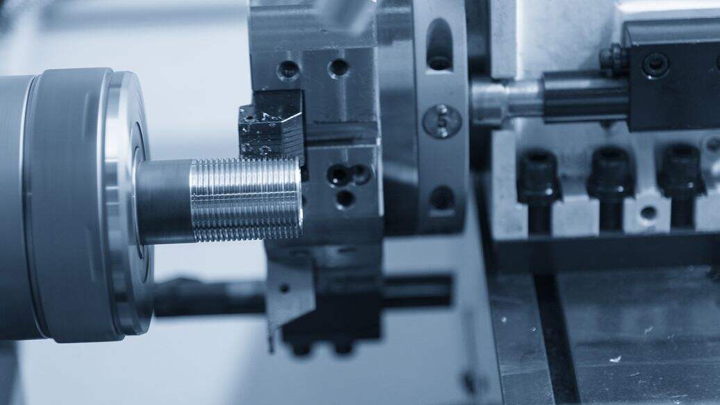
CNC-де бұрғылау кезінде өңделетін бөлшек айналады, ал қозғалмайтын кескіш құрал оның бетімен қозғалады. Бұл цилиндрлі бөлшектерді, мысалы, сақиналарды, втулкаларды және тісті бекітпелерді өңдеуге идеалды болып табылады. Бұл үдеріс гладкий сыртқы диаметрлерді, ішкі тесіктерді және өте жақсы концентрикалықты қамтамасыз ететін конусты беттерді жасауда өте жоғары сапалы.
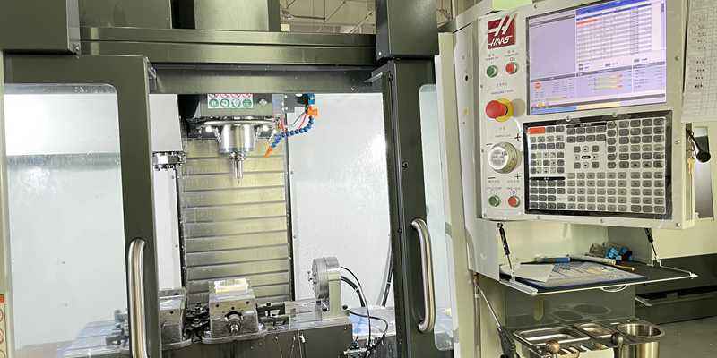
CNC фрезерлеу әдісінде рөлдер ауысады. Мұнда кескіш құрал айналады, ал өңделетін бөлшек қозғалмайтын немесе бірнеше ось бойымен қозғалады. Фрезерлеу операцияларын орындайтын CNC кескіш машинасы жазық беттерді, ойықтарды, қалташаларды және бұрғылау әдісімен жасауға болмайтын күрделі 3D контурларды шығара алады. Егер сіздің дизайнда әртүрлі бұрыштарда орналасқан элементтер бар немесе көпжақты өңдеу қажет болса, онда фрезерлеу — сіздің негізгі шешіміңіз болып табылады.
Қазіргі көпосьлы CNC фрезерлеу станоктары мүмкіндіктерді тағы да кеңейтеді. Бес осьті станоктар өңделетін бөлшектің кез келген бұрышынан жақындай алады, ол аэроғарыштық кешендер мен медициналық құрылғыларды бір реттік орнату арқылы CNC фрезерлеуге мүмкіндік береді. Бұл өңдеу уақытын қысқартады және дәлдікті жақсартады, себебі бөлшек операциялар арасында қайта орналастырылмайды.
Қашан құрғақ өңдеу мен әйнек өңдеу мағынасы бар
Құрғақ өңдеу мен әйнек өңдеу әдетте фрезерлеу мен иілумен бірге жұмыс істейді, олардың орнын алмайды. Оларды белгілі бір қиындықтарды шешуге арналған мамандандырылған құралдар ретінде қарастырыңыз.
Құрғақ өңдеу — бұл өткізгіш тесіктер, жасырын тесіктер немесе конусты тесіктер сияқты тесіктерді жасау. Фрезерлеу станоктары цилиндрлі фрезаларды пайдаланып тесіктерді жасай алады, бірақ көп көлемді тесік жасау үшін бұрғылау операциялары мен айналмалы бұрғылар немесе мамандандырылған бұрғылар әлдеқайда тезірек және экономикалық тиімді. Әрбір болт тесігі, орналасу тесігі немесе сұйықтық өткізгіші әдетте бұрғылау операциясынан басталады.
Басқа әдістер сенімді түрде қамтамасыз ете алмайтын өте жоғары сапалы беттік өңдеу немесе өте тар шектеулерді қажет еткен кезде ұнтақтау процесі қолданысқа енеді. Фрезерлеу немесе кесіп тегістеу арқылы CNC-мен өңделген бөлшек IT7 дәрежесіндегі шектеулерге жетуі мүмкін, ал ұнтақтау IT6 немесе IT5 дәрежесіне дейін жетеді және 0,4 мкм Ra-дан төмен, айна сияқты беттік өңдеу береді. Жылумен өңдеуден кейін бөлшектің қаттылығы артқаннан кейін ұнтақтау – оның аздап бұралуын түзетуге және соңғы өлшемдерге жетуге арналған жалғыз тиімді әдіс болып табылады.
Өңдеу процесін бөлшектің геометриясына сәйкестендіру
Дұрыс әдісті таңдау – әрбір әдістің нені жақсы орындайтынын түсінумен анықталады. Бұл салыстыру кестесін тез анықтау үшін пайдаланыңыз:
| Процесс | Типілік қолданулар | Жетуге болатын дәлдік | Бетінің тегістігі (Ra) | Идеал бөлшек геометриясы |
|---|---|---|---|---|
| CNC бұрау | Осьтер, ілгектер, тісті бөлшектер, роликті тірек муфтасы | IT10–IT7 | 12,5–1,6 мкм | Цилиндрлі, осьтік симметриялы бөлшектер |
| CNC фрезерлеу | Корпустар, кронштейндер, плиталар, күрделі 3D беттер | IT10–IT7 | 12,5–1,6 мкм | Призматикалық, көп сипаттамалы, контурлы бөлшектер |
| Жинау | Болт тесіктері, орналастыру тесіктері, сұйықтық өткізгіш каналдары | IT12–IT10 | >12,5 мкм (қатты) | Әртүрлі тереңдік пен диаметрлері бар тесік сипаттамалары |
| Жиып алу | Рулонды және бағыттаушы рейкалар, қатайтылған беттер | IT6–IT5 | 1,6–0,1 мкм | Жоғары дәлдікті жабылу немесе аз шамадағы өлшемдік бақылау қажет ететін беттер |
Жобаңызды бағалаған кезде осы сұрақтарға жауап беріңіз:
- Бөлшек негізінен дөңгелек немесе цилиндрлік пішінді ме? Алдымен токарьлау операциясын қарастырыңыз.
- Дизайнда жазық беттер, қалташалар немесе бұрышты сипаттамалар бар ма? Бұларды фрезерлеу әдісі тиімді өңдейді.
- Бірнеше тесік қажет пе? Арнайы тесіктеу операциялары уақыт пен құнын үнемдейді.
- Соңғы техникалық сипаттама беттік өңдеуді Ra 1,6 мкм-ден төмен немесе IT7-ден қатаңырақ дәлдіктерді талап ете ме? Соңғы өңдеу ретінде ғайыптау процесін жоспарлаңыз.
Көптеген нақты әлемдегі бөлшектер көптеген өңдеу процестерін талап етеді. Гидравликалық клапан денесі цилиндрлік ойығы үшін CNC айналдырумен басталуы, орнату беттері мен порт элементтері үшін фрезерлеуге ауысуы, содан кейін маңызды герметик беттерді ғайыптау арқылы аяқталуы мүмкін. Бұл операциялар бойынша CNC кесулерінің өзара әсерлесуін түсіну сізге тәрбиешілермен тиімдірек қарым-қатынас жасауға және артық шығындардан аулақ болуға көмектеседі.
Өңдеу процестерін таңдау анықталғаннан кейін келесі маңызды шешім — қолданыңызға сәйкес металды таңдау, бұл таңдау өңделуге қабілеттілігі мен соңғы бөлшектің жұмыс істеу сапасына әсер етеді.
Өңделетін бөлшектеріңіз үшін дұрыс металды таңдау
Сіз өз жобаңыз үшін дұрыс механикалық өңдеу процесін таңдадыңыз. Енді бір бөлшекке кететін шығыннан бастап ұзақ мерзімді жұмыс істеу сапасына дейін барлығын әсер ететін шешім қабылдау кезегі келді: материалды таңдау. Қызығы, көптеген тұтынушылар өзіңіздің нақты қолданысыңыз үшін бір нұсқаның басқасынан неге тиімдірек екенін түсіндірмей-ақ материалдың мүмкін нұсқаларын ұсынады. Осы білім аймағындағы кемшілікті жоюға тырысайық.
Жеңіл және дәлдік қасиеттері үшін алюминий қорытпалары
Егер сіз аллюминийді механикалық өңдеуді басымдық ретінде таңдасаңыз, сіз көптеген қолданыстар үшін ең тиімді және универсалды опцияны таңдайсыз. Аллюминий қорытпалары өте жақсы беріктік-салмақ қатынасын, табиғи коррозияға төзімділікті және өндіріс шығындарын төмендететін өте жақсы өңделу қасиетін ұсынады.
Бірақ сіз қандай марканы көрсетуіңіз керек? Жауап сіздің жұмыс сипаттамаларыңызға байланысты:
Алюминий 6061 қоңырпайыздардың дүниеге сійкес өзгерткіш ретінде шығады, жалпы мақсаттағы қолданыстар үшін негізгі марка . Ол өте жақсы өңделеді, оңай дәнекерленеді және беттің қаттылығы мен коррозияға төзімділігін арттыру үшін анодтауға жақсы түседі. Егер сіз прототип құрып жатсаңыз немесе өте жоғары беріктік талап етпейтін бөлшектер шығарсаңыз, 6061 маркасы әдетте ең тиімді нұсқаны ұсынады.
Алюминий 7075 беріктік маңызды болған кезде қолданылады. Әдетте әуе-ғарыш қолданыстарында кездесетін бұл қорытпа қыздыру арқылы болаттардың кейбіреулерімен салыстырғанда қаттылық деңгейін қамтамасыз етеді, бірақ алюминийдің салмақтық артықшылығын сақтайды. Алайда оның кемшілігі — 6061 қорытпасымен салыстырғанда материалдың құны жоғары және өңдеуге беріктігі шамалы төмен.
Екі де маркасы анодталуға болады: II типті анодтау әр жағына шамамен 5 мкм, ал III типті (қатты анодтау) әр жағына 12–25 мкм қабат қалыңдығын құрайды. Критикалық элементтерді өлшемдеу кезінде осы қабат қалыңдығының өсуін ескеріңіз.
Болат пен коррозияға төзімді болатты таңдау критерийлері
Жоғары беріктік, тозуға төзімділік немесе қиын жағдайларда жұмыс істеу қабілеті қажет пе? Коррозияға төзімді болаттар мен қорытпалы болаттар алюминийдің қол жеткізе алмайтын сипаттамаларын ұсынады.
Қарастырыңыз 303 маркалы штайнс таспалы болат жоғары көлемді өндірісте өте жақсы өңделу қабілеті қажет болған кезде. Оның күкіртінің мазмұны стружканың үзілуін жақсартады және кесу жылдамдығын арттырады, сондықтан ол гайкалар, бұрандалар және қосылымдар үшін идеалды. Алайда оның кемшілігі — туыстас маркаларымен салыстырғанда коррозияға төзімділігі шамалы төмен.
Қалтадан жасалған жалпы коррозияға төзімді қолданыстар үшін ең кең таралған таңдау болып табылады. Ол көптеген айналыс ортасы жағдайлары мен коррозиялық орталарды тиімді түрде ұстайды, бірақ 303-ке қарағанда баяу өңделеді.
Теңіз ортасында, химиялық өңдеуде немесе медициналық қолданыста, sT Steel 316L хлоридтер мен тұзды ерітінділерге қарсы аса жоғары коррозияға төзімділік қамтамасыз етеді. «L» белгісі төмен көміртегі құрамын көрсетеді, бұл пішіндеу қабілетін жақсартады және карбидтің тұнбаға шөгуін азайтады. Салалық нормативтік құжаттарға сәйкес, SS316L медициналық және фармацевтикалық компоненттер үшін ең жоғары тазалық талап етілетін жағдайларда электрополировкаланады.
Қиын шарттардағы қолданыстар үшін арнайы металдар
Кейбір жобалар стандартты алюминий мен шойын болаттан тыс материалдарды талап етеді. Дәл осы жерде мамандандырылған металдар өзіндік жоғары бағасын қамтамасыз етеді:
360 мыс (C36000) кез келген металдың ішінде ең жоғары токарьлық өңдеуге қабілеттілік көрсеткіштерінің бірін ұсынады. Егер сіздің қолданысыңызда жоғары электр өткізгіштігі, төмен үйкеліс немесе декоративті алтын тонды түрі қажет болса, мыс-қалайы қорытпаларын өңдеу жоғары өндірістік жылдамдықта өте жақсы нәтижелер береді. Мыс қорытпаларының қолайлы өңделу сипаттамалары арқасында CNC-пен мыс өңдеу операциялары тиімді өтеді; CNC-мен өңделген мыс бөлшектері жиі электрлік коннекторларда, клапандар компоненттерінде және әрлеу құрылыс фурнитурасында қолданылады. C36000 сияқты мыс қорытпаларын өңдеген кезде құралдың қызмет ету мерзімінің айналасында 30–50% артуын күтіңіз — бұл шамамен тозымды болатпен жұмыс істегендегі көрсеткішке қарағанда.
Титан космостық және медициналық импланттар саласындағы қолданыстар үшін назар аудартады, мұнда беріктіктің массаға қатынасы мен биологиялық үйлесімділік ең маңызды факторлар болып табылады. Қиын өңдеу жылдамдығы, арнайы құрал-жабдықтар және алюминийге қарағанда 3–5 есе қымбат тұратынын ескеріңіз.
Күміс жылу және электр өткізгіштігін қолдану саласында өте жақсы көрсеткішке ие. Көпшілік өңдеу материалдарына қарағанда жұмсақ болғанымен, оның бетін таза қалдыру үшін және шеттерінің бұрылуын (бурлау) болдырмау үшін құрал геометриясы мен кесу параметрлеріне мұқият назар аудару қажет.
Материалды таңдау: қысқаша шолу
Жобаңыздың талаптарына материалдарды жылдам сәйкестендіру үшін осы салыстырмалы кестені пайдаланыңыз:
| Материал | Өңдеуге ыңғайлылық бағасы | Типілік қолданулар | Құны туралы қарым-қатынас | Негізгі механикалық қасиеттер |
|---|---|---|---|---|
| Алюминий 6061 | Керемет | Жалпы мақсаттағы бөлшектер, прототиптер, корпуслар | Төмен | Жақсы беріктік, өте жақсы коррозияға төзімділік, дәнекерленуге болады |
| Алюминий 7075 | Жақсы | Әуе-ғарыш компоненттері, жоғары кернеу әсер ететін қолданбалар | Орташа | Жоғары беріктік (жылумен өңделуге болады), өте жақсы циклдық төзімділік |
| Коррозияға төзімді болат 303 | Жақсы | Жоғары көлемді бекітпе бұрандалары, әуе-ғарыш ілгектері | Орташа | Өте жақсы соққыға төзімділік, қанағаттанарлық коррозияға төзімділік |
| Қалтадан жасалған | Орташа | Тамақ өнеркәсібінің жабдықтары, химиялық сыйымдылықтар, жалпы қолданыс | Орташа | Өте жақсы коррозияға төзімділік, қанағаттанарлық дәнекерленуге қабілеттілік |
| Тот баспайтын болат 316L | Орташа | Теңіз техникасы, медициналық құрылғылар, химиялық өңдеу | Орташа-жоғары | Жоғары коррозияға төзімділік, қатал орталар үшін өте жақсы |
| Қорғасынды мыс қорытпасы C36000 | Әдеттен тыс | Электрлік қосқыштар, клапандар, декоративті бөлшектер | Орташа | Жоғары өткізгіштік, төмен үйкеліс, табиғи коррозияға төзімділік |
| Титан | Нашар | Әуе-ғарыш конструкциялары, медициналық импланттар | Жогары | Өте жоғары беріктік-салмақ қатынасы, биологиялық үйлесімді |
| Күміс | Жақсы | Жылу шашуыштар, электрлік шиналар, жылулық компоненттер | Орташа-жоғары | Ең жоғары жылулық/электрлік өткізгіштік |
Сіздің материалды таңдауыңыз үшін негізгі факторлар
Материалды таңдаудың соңғы кезеңіне кірмес бұрын, осы маңызды факторларды бағалаңыз:
- Жазықтық талаптары: Бұл бөлшек конструкциялық жүктемелерді көтере ме, циклдық әсерге ұшырай ма немесе соққыға тұрақты бола ма?
- Коррозияға төзімділік: Бұйым қандай ортада жұмыс істейді? Немесе ылғалға, химиялық заттарға, теңіз суына немесе жоғары температураға ұшырауын ескеріңіз.
- Салмақ шектеулері: Сіздің қолданысыңызда (мысалы, әуе-ғарыш саласында немесе тасымалданатын жабдықтарда) массаны азайту маңызды ма?
- Жылусақтау қасиеттері: Бұйым жылу өткізгіштігін тиімді қамтамасыз етуі немесе температура ауқымы бойынша тұрақтылығын сақтауы керек пе?
- Бюджет: Материалдың құны бір бұйымға келетін бағаны тікелей әсер етеді. Жоғары өңделу бағасы да өңдеу уақытын және құралдың тозу шығындарын азайтады.
Материалдың таңдалуы тек сатып алу бағасына ғана әсер етпейді. Мысалы, титан сияқты қатты материалдар кесу жылдамдығын баяулатады және құралдың тозуын жылдамдатады, нәтижесінде өңдеу шығындары артады. Ал алюминий мен мыс сияқты жұмсақ материалдар тез кесіледі және құралдың қызмет ету мерзімі ұзақ болады, ол өндірістің жалпы шығындарын азайтады — тіпті шикізаттың құны ұқсас болса да.
Материал таңдалғаннан кейін келесі сұрақ: шынымен қаншалықты дәлдікке қажеттілік бар? Бұл сұраққа берілетін жауап көптеген сатып алушылардың ойлағанынан көбірек шығындарға әсер етеді.
Шынымен маңызды болатын дәлдіктер мен беттің жаңғыртуы
Бұл — көптеген тәжірибелік тұтынушылар сізге айтпайтын нәрсе: қолданыстағы қажеттіліктен қатаңдаурақ дәлдік шектерін көрсету сіздің өңдеу шығындарыңызды екі немесе үш есе арттыруы мүмкін. Ал шектерді біраз жеңілдету — жинақтау ақаулары мен өнімнің жаман жұмыс істеуіне әкелуі мүмкін. Дәлдіктің шынымен маңызды болатын орындарын және оның маңызды емес орындарын түсіну — құндылығы тиімді жобаларды бюджеттік апаттардан ажыратады.
Дәлдік шектерінің класстарын түсіну және олар қашан маңызды болады
Дәлдік шектерін — мақсатты өлшемнен қабылданатын ауытқу ретінде қараңыз. Сіз 10,00 мм диаметрлі тесікке ±0,05 мм дәлдік шегін көрсеткен кезде, сіз өңдеушіге 9,95 мм мен 10,05 мм арасындағы кез келген мәннің толықтай қанағаттандыратынын хабарлайсыз. Ал егер сіз осы шекті ±0,01 мм-ге дейін қатаңдатсаңыз, не болады?
Бірден, станокшыға қиылу жылдамдығын баяулату, құралдарды жиі ауыстыру және мүмкін болған жағдайда мамандандырылған жабдықтар қажет болады. Толеранцияның әрбір келесі азайтуы осы талаптарды күшейтеді. Дәлме-дәл өңдеу қызметтері үшін стандартты және тар толеранциялы жұмыстар арасындағы айырмашылық жиі жалпы мақсаттағы станоктардан термиялық компенсация жүйелері бар жоғары дәлдікті CNC-станоктарға ауысуға әкеледі.
Төменде кеңінен қолданылатын толеранция диапазондары мен олардың нақты әлемдегі әсерлерінің тәжірибелік талдауы келтірілген:
- ±0,10 мм (±0,004 дюйм): Стандартты жалпы өңдеу. Критикалық емес өлшемдерге, сыртқы контурларға және басқа компоненттермен өзара әрекеттеспейтін элементтерге қолданылады.
- ±0,05 мм (±0,002 дюйм): Стандартты дәлме-дәл өңдеу. Көптеген функционалды элементтерге, орнату тесіктеріне және жалпы жинау интерфейстеріне қолданылады.
- ±0,02 мм (±0,0008 дюйм): Жоғары дәлдікті өңдеу шешімдері. Рулонды тірек орындарына, реттеу элементтеріне және қосылатын бөлшектер арасындағы дәл келулерге қажет.
- ±0,01 мм (±0,0004 дюйм) немесе тағы да тарырақ: Аса дәл жұмыс. Микрон деңгейіндегі дәлдік тікелей өнімнің қызмет көрсету сапасына әсер ететін маңызды функционалды интерфейстерге, орнату беттеріне және компоненттерге арналған.
Сіздің жобаңыз үшін CNC өңдеу бөлшектерін бағалайтын кезде өзіңізге сұрақ қойыңыз: егер бұл өлшем тағы да 0,1 мм-ге өзгерсе, не болады? Егер жауап «ештеңе маңызды болмайды» болса, сіз қызмет көрсетудің сапасын төмендетпей-ақ шығындарды азайтуға мүмкіндік алдыңыз.
Беттің жабылу стандарттары түсіндірілген
Беттің жабылуы — бұл өңделген беттерде қалатын беттің дәлдігін сипаттайтын параметр; ол Ra (орташа кедір-бұдырлылық) түрінде микрометр (μm) немесе микродюйм (μin) өлшемінде өлшенеді. Әрбір CNC операциясы көрінетін құрал іздерін қалдырады, ал гладкий бетті алу үшін қосымша өңдеу өтпелері, арнайы құралдар немесе екіншілік жабылу операциялары қажет.
Стандарттық өңделген беттің көрсеткіші әдетте шамамен 3,2 мкм (125 мкдюйм) Ra құрайды. Бұл көрінетін құралдың ізін көрсетеді, бірақ ішкі беттерге, жасырын элементтерге және сыртқы түрі маңызды емес компоненттерге өте жақсы сай келеді. Hubs деректері бойынша, өңдеу өтісі Ra-ны 1,6, 0,8 немесе 0,4 мкм-ге дейін төмендетуге болады, ал әрбір жақсарту өңдеу уақыты мен құнын арттырады.
| Ra мәні | Беттің сипаттамасы | Оны қалай алуға болады | Қолдануға ыңғайлы орындар |
|---|---|---|---|
| 3,2 мкм (125 μin) | Стандартты өңделген | Қалыпты CNC фрезерлеу/айналдыру операциялары | Ішкі беттер, көрінбейтін бөліктер, эстетикалық талаптары жоқ функционалды компоненттер |
| 1,6 мкм (63 мкдюйм) | Дәл тегіс өңделген | Төмендетілген берілу жылдамдығымен өңдеу өтісі | Көрінетін беттер, жалпы дәлдікті қажет ететін компоненттер, бір-бірімен жанасатын беттер |
| 0,8 мкм (32 мкдюйм) | Өте жіңішке өңделген | Жарық жабылу кесімдері, тегіс ұнтақты құралдар | Орнату беттері, жұмыс істейтін бұрандалар, гидравликалық компоненттер үшін дәл металдандыру |
| 0,4 мкм (16 мкдюйм) | Жылтыратылған | Тегістеу немесе жылтырату операциялары | Оптикалық беттер, медициналық немесе ғарыштық қолданыстар үшін жоғары дәлдікті металдандыру қызметтері |
| < 0,4 мкм | Айна сияқты бет | Лаппинг, супертегістеу немесе электрлік жылтырату | Шағылысушы беттер, ультрадәл орнату, арнайы ғылыми жабдықтар |
Токарлауға ұшыраған алюминий мен басқа жұмсақ металдар үшін жақсы жабылу алу қиын емес, ал темірбетон немесе титан сияқты қатты материалдармен салыстырғанда оңайырақ. Материалдың өңделу қабілеті тікелей экономикалық тұрғыдан қол жетімді бет сапасына әсер етеді.
Дәлдікті өндіріс шығындарымен теңестіру
Бұл — баға ұсыныстары жиі жасыратын шынайы шығындар: ±0,10 мм-ден ±0,01 мм-ге дейінгі дәлдік шегін өзгерту өңдеу шығындарын 200–400% арттыруы мүмкін. Сол сияқты, беттің Ra көрсеткішін 3,2 мкм орнына 0,4 мкм етіп көрсету бөлшектің бір данасы үшін бағаны қосымша операциялар мен цикл уақытының ұзақтығы арқасында екі есе арттыруы мүмкін.
Ақылды дәлдік шектерін белгілеу — функциялық талаптар қажет еткен жерлерде ғана қатаң талаптарды қолдану дегенді білдіреді. Осы нұсқауларға назар аударыңыз:
Қатаң дәлдік шектері шынымен қажет болған кезде:
- Өлшемдік дәлдік жиылу сипатын бақылайтын подшипник отырғызу орындары мен престік қосылыс аймақтары
- Саңылаулар салдарынан сұйықтық немесе қысым жоғалуы пайда болатын тығыздау беттері
- Басқа компоненттерді дәл орналастыратын реттеу элементтері
- Жоғары жылдамдықта айналып тұратын құрылымдардағы қосылатын беттер
- Реттеуші органдардың дәлдік талаптарын қанағаттандыратын медициналық немесе әуе-ғарыштық компоненттер
Стандартты дәлдік шектері жеткілікті болған кезде:
- Функционалдық қосылыстары жоқ сыртқы контурлар мен көркемдік беттер
- Бекіткіштер үшін кеңістігі жеткілікті болатын тесіктер
- Көрінбейтін ішкі элементтер және олардың жұмыс өнімділігіне әсері жоқ
- Дизайнды растау өндірістік деңгейдегі дәлдіктен гөрі маңызды болатын прототип бөлшектер
- Дәл келу талаптары жоқ кронштейндер, қаптамалар және конструкциялық компоненттер
HM-ның дәлдік шектері бойынша нұсқауларға сәйкес инженерлер «қауіпсіздік үшін» дәлдік шектерін артық көрсетеді, бірақ бұл тәсіл функцияны жақсартпай, тек шығындарды арттырады. Жақсы стратегия — функция үшін маңызды өлшемдерді анықтау және оларды тұтынушыңызға анық түсіндіру, ал басқа жерлерде талаптарды жеңілдету.
Ескеріңіз: бірнеше элемент бойынша дәлдік шектерінің жиналуы ауытқуды күшейтеді. Егер құрама бірлестігіңізде әрқайсысы ±0,05 мм дәлдік шегі бар бес қосылатын бөлшек болса, соңғы қосылу аймағында жинақталған ауытқу ±0,25 мм-ге жетуі мүмкін. Жоғары дәлдікті токарьлау қызметтері бұған «барлық жерде жалпы қатаң дәлдік шектерін» қолдану орнына позиция және концентрикалықтық сияқты ГД&Т (Геометриялық өлшемдік және техникалық талаптар) бақылауын қолдану арқылы шешім ұсынады.
Дәлдік шектері мен беттің жағдайы дұрыс көрсетілген кезде, келесі логикалық сұрақ мынадай болады: сіздің баға ұсынысыңыздағы соңғы құнды не анықтайды? Жауап өндірушілер құпия ұстап тұрғысы келетін факторларға негізделеді.
Токарьлау шығындарына әсер ететін факторларды түсіну
Сіз онлайн токарьлау бағасын сұраған кезде, өндірушілер осы сандарды қалай анықтайтынын ойланған шығарсыз? Көптеген бәсекелестер бағалау логикасын сәттік баға ұсынысы формаларының артында жасырады, сондықтан сізге шығындардың жоғары немесе төмен болуына не әсер ететіні туралы тек қана болжам жасауға тура келеді. Біз осы «перде» артындағы құпияларды ашып, сізге дәлірек құрылған бөлшектердің бюджетін құру кезінде қажетті ашықтықты ұсынамыз.
Металл токарьлау шығындарына әсер ететін факторлар
Кез келген токарьланған бөлшектің жалпы құны бес негізгі факторға бөлінеді. Әрбір факторды түсіну сізге дизайн және жабдықтау шешімдерін тиімдірек қабылдауға көмектеседі:
- Материалдық траттар: Шикізат бағасы әртүрлі болады. Мысалы, алюминийдің қоймалық қоры килограмына $5–15, ал титан килограмына $50–100-дан аса болуы мүмкін. Бұл баға нарықтық тербелістерге, қорытпаның маркасына және бастапқы заготовканың өлшеміне байланысты.
- Жабдық уақыты: Бұл әдетте ең үлкен шығын компонентін құрайды. Саладағы баға деректеріне сәйкес, 3 осьті фрезерлеу мен итеру бойынша сағаттық ставкалар $70–125 аралығында, ал 5 осьті өңдеу бойынша — $150–250 болады. Күрделі геометриялар қосымша құрал жолдарын талап етеді, ол цикл уақытын ұзартып, шығындарды көтереді.
- Орнату күрделілігі: Әрбір тапсырма үшін станокты дайындау қажет: детальды бекіту, құралдарды орнату және бағдарламаны іске қосу. Бұл бір реттік шығын тапсырыс саны бойынша бөлінеді, сондықтан кіші партияларда бір бөлікке келетін дайындық шығыны жоғары болады.
- Дәлдік талаптары: Дәлелденгендей, тарылған допустимдіктер баяу қоректендіруді, жиірек құрал ауыстыруды және қосымша бақылау уақытын талап етеді. Стандарттық талаптардан дәлдеу сипаттамаларына өту өңдеу шығындарын 200–400% арттыруы мүмкін.
- Екінші кезектегі операциялар: Жылумен өңдеу, беттік өңдеу, металл көмегімен қаптау және бақылау — бұлар барлығы негізгі механикалық өңдеуден тыс қосымша шығындарды құрайды. Қарапайым алюминийдің тірек бөлігі үшін тек орындарды тазарту ғана қажет болуы мүмкін, ал қаттылатылған болат тісті дөңгелектің жылумен өңделуі, өңдеуі және қорғаныс қабатымен қапталуы қажет.
Бөлшектің геометриясы тікелей сіздің төлейтін құныңызға әсер етеді. Терең қуыстар ұзын құралдарды талап етеді, олар баяу қиылады және оңай иіледі. Жұқа қабырғалар бұралуға ұшырамау үшін қиылу күштерін азайтуды талап етеді. Күрделі контурлар арнайы құралдар мен көпосьті мүмкіндіктерді талап етеді. Әрбір механикалық өңдеуді қиындататын конструкциялық шешім цикл уақытын және құралдың тозуын арттырады.
Сан бойынша жеңілдіктер және партиялық экономика
Мұнда шығындар құрылымын түсіну шынымен тиімді болады. Тәжірибелік үлгіден сериялық өндіріске көшу кезіндегі шығындар қисығы болжанатын үлгі бойынша өзгереді, бұл үлгіні көптеген тағайындаушылар түсіндірмейді.
Жеке тәжірибелік үлгі үшін сіз толық бастапқы дайындық шығынын төлейсіз, ол күрделілігіне байланысты $100–300 болуы мүмкін. Орнына 100 дана бірдей бөлшек тапсырысын берсеңіз, осындай бастапқы дайындық шығыны әр бірлікке $1–3-ке дейін таралады. Сондықтан да өндірістік көлемде тапсырылған қосымша металдан жасалған бөлшектердің бағасы тәжірибелік үлгілердің бағасынан бірнеше есе арзан болады.
Бұл – нақты әлемдегі мысал: Қарапайым алюминийдің кронштейні үшін жеке дана үшін баға $85 болуы мүмкін, ал бастапқы дайындық шығыны осы бағаның шамамен 60%-ын құрайды. 50 дана тапсырысын берсеңіз, бірлік бағасы $18-ге дейін төмендейді. 500 дана тапсырысында бір бөлшектің бағасы $8–10 аралығында болуы мүмкін. Бір бөлшектің өңдеу уақыты тұрақты қалады, бірақ тұрақты шығындар ескерілмейтін деңгейге дейін азаяды.
Сіз онлайн арқылы CNC бағасын сұрасаңыз, тағайындаушылар бұл шекті нүктені автоматты түрде есептейді. Бұл логиканы түсіну сізге стратегиялық тапсырыс беру шешімдерін қабылдауға көмектеседі. Егер келесі жыл ішінде сізге көбірек бөлшек қажет болса, қоймада сақтау шығындарын ескере отырып таңдағанда, алдын ала ірі партиялар тапсыру әдетте қаржылық тұрғыдан тиімді болады.
Ақшаны үнемдейтін дизайн шешімдері
Ең қуатты шығындарды азайту — сіз баға сұранысын жібергенше болады. Өндіріске ыңғайлы дизайн (DFM) принциптері функцияны төмендетпей-ақ бір бұйымға кететін шығындарды 20–50% азайта алады. Fictiv компаниясының DFM нұсқаулығына сәйкес, өнімнің дизайны шамамен өндіріс шығындарының 80%-ын анықтайды, ал дизайны рәсімделгеннен кейін инженерлер шығындарды азайту үшін көп мүмкіндікке ие болмайды.
Құндық тиімділігі жоғары қосымша бөлшектерді өндіруге арналған іс-әрекетке қабілетті кеңестер:
- Геометрияны ықшамдау: Функционалды талаптарды қанағаттандырмайтын элементтерді жойыңыз. Әрбір ойық, тесік және контур станокта өңдеу уақытын ұзартады. Әрбір элементтің нақты қажеттілігін сұраңыз.
- Терең қуыстар мен жұқа қабырғалардан аулақ болыңыз: Терең қуыстар арнайы ұзын қолданылатын құралдарды талап етеді, олар баяу кеседі және тез тозады. Жұқа қабырғалар вибрация мен деформацияны болдырмау үшін ұқыпты өңдеу стратегияларын талап етеді.
- Стандартты тесік өлшемдерін қолданыңыз: Жиі қолданылатын бұрғылау өлшемдерін (мысалы, 6,35 мм емес, 6 мм) көрсету станокшыларға дайын құралдарды пайдалануға, ал қосымша бұрғыларды емес, мүмкіндік береді.
- Мүмкіндігінше стандартты допускаларды көрсетіңіз: Қатаң допускаларды тек функционалды интерфейстерге қолданыңыз. Критикалық емес өлшемдерді ±0,02 мм-ден ±0,10 мм-ге дейін жеңілдету шығындарды қатты төмендетуге мүмкіндік береді.
- Орнатуларды азайтыңыз: Бір немесе екі бағытта ғана өңделетін бөлшектерді жобалаңыз, көптеген қайта орналастыру операцияларын қажет етпейтіндей етіп. Әрбір орнату уақытты ұзақтандырады және потенциалды туралау қателерін туғызады.
- Шығындарды төмендетуге бағытталған материалдарды таңдаңыз: Сіздің қолданысыңызға рұқсат берілсе, 316L маркалы шойын болатының орнына 6061 маркалы алюминийді таңдау материалдық шығындарды 60–70% дейін төмендетеді және өңдеуге қолайлылықты жақсартады.
Жобалау сатысының ерте кезеңінде тәжірибелі тұтынушымен жұмыс істеу сіз өзіңіз таба алмайтын үнемдеу мүмкіндіктерін ашуға көмектеседі. Көптеген қосымша бөлшектерді өндіретін серіктестер DFM-ті (жасауға ыңғайлы жобалау) қайта қарауды ұсынады, олар өндіріс басталмас бұрын шығындарды анықтайды және сіздің жұмыс сипаттамаларыңызды сақтай отырып, жобаны оптимизациялауға көмектеседі.
Бұл шығын факторларын түсіну сізді күштірек келісімшартқа отыруға және баға ұсыныстарының нақты құннан айырылып кеткенін анықтауға көмектеседі. Алайда, беттік өңдеу (фрезерлеу) әдетте соңғы кезең болмайды. Бөлшектер станоктан шыққаннан кейінгі процестер сіздің компоненттеріңіздің нақты қолданыста қалай жұмыс істейтінін анықтайды.
Кейінгі өңдеу және екіншілік операциялар
Сіздің бөлшектеріңіз CNC-станоктан шығып, өте жақсы көрінеді, бірақ олар шынымен пайдалануға дайын ба? Төмендегі сырды көптеген тараптар өткізіп жібереді: беттік өңдеу (фрезерлеу) әдетте тек бастапқы кезең болып табылады. Кейінгі өңдеу операциялары шикі фрезерленген компоненттерді нақты қолданыста сенімді жұмыс істейтін бөлшектерге айналдырады. Дегенмен, бәсекелестер кейінгі өңдеу тәсілдері қашан маңызды болатынын немесе олардың сіздің уақыт кестесіңіз бен бюджетіңізге қалай әсер ететінін сирек түсіндіреді.
Жақсартылған өнімділік үшін жылумен өңдеу
Жылумен өңдеу — металдың ішкі құрылымын өзгертетін, сыртқы геометриясын өзгертпейтін бақыланатын қыздыру мен салқындату циклдерінен тұрады. Federal Group USA дерегіне сәйкес, бұл процестің болжанатын реті мынадай: белгілі бір температураға дейін қыздыру, біркелкі температураның таралуы үшін осы температурада ұстап тұру, содан кейін қажетті қасиеттерді алу үшін бақыланатын жылдамдықпен салқындату.
Бірақ сіздің жобаңызға жылумен өңдеу қашан қажет болады? Осы жиі кездесетін қолданыстарды қарастырыңыз:
- Қатайту: Тісті берілістер, валдар және кесу құралдары сияқты бөлшектердің беттік қаттылығын және тозуға төзімділігін арттырады. Тез салқындату (шайыту) жоғары тозуға төзімді қолданыстар үшін идеалды қатты мартенситтік құрылымды қалыптастырады.
- Стрессден шығу: Токарлау кезінде пайда болған ішкі керілуді жояды, бұл уақыт өте келе бұралуға немесе өлшемдік өзгерістерге себепші болмайды. Дәлме-дәл бөлшектер үшін, яғни тар шектерде жасалған бөлшектер үшін маңызды.
- Темперлеу: Материалдың өңдеуін жақсарту үшін немесе суық деформациядан кейін пластикалығын қалпына келтіру үшін жұмсартады. Баяу салқындату күшейтілген тұрақтылыққа ие болатын жетілдірілген дән құрылымын береді.
- Темперлеу: Қатайтудан кейін әрекет етеді, бірақ қаттылықтың көп бөлігін сақтай отырып, хрупкостьті азайтады. Қиын жағдайларда қолданылатын қолданыстағы қаттылық пен тұрақтылықты теңестіреді.
Жылумен өңдеу кезінде уақыттың маңызы зор. Керілулерді жою сияқты кейбір операциялар өлшемдік тұрақтылықты қамтамасыз ету үшін соңғы өңдеу өтістерінен бұрын жүргізіледі. Басқалары, мысалы, беттік қатайту, өңдеуден кейін жүргізіледі, бірақ жылу әсерінен пайда болған аздап бұрмалануларды түзету үшін кейіннен шлифтау қажет болуы мүмкін.
Қорғаныштық қаптамалар мен гальваникалық қаптама нұсқалары
Беттік өңдеулер коррозияға қарсы, үйкелісті азайтатын немесе сыртқы түрін жақсартатын қорғаныш қабаттарын қосады. Дұрыс таңдау сіздің жұмыс ортасыңызға және өнімділік талаптарыңызға байланысты.
Қаптау электрохимиялық процестер арқылы бөлшектің бетіне жұқа металл қабатын тұндырады. Сәйкесінше ADDMAN Group никель, хром және цинк — ең көп қолданылатын гальваникалық қабаттау металдары. Әрқайсысы өзіндік артықшылықтарға ие: никель өте жақсы коррозияға төзімділік қасиетін қамтамасыз етеді және қаттылықты арттыруға мүмкіндік береді; хром көркем, жарқыраған сыртқы бет пен тозуға төзімділік қасиетін қамтамасыз етеді; ал цинк болса, болат бөлшектерге экономикалық коррозияға қарсы қорғаныс ұсынады.
Ұнтақ жабыны құрғақ порошкалы материал электростатикалық әдіспен салынады да, одан кейін тұрақты қорғаныс қабатын түзу үшін жылумен қатайтылады. Бұл процесстер коррозия мен тотығуға төзімділік маңызды болатын ашық алаңдарда қолдануға өте жарамды. Порошкалы сырлау кез келген түске және дәнекерленген бетке ие болуы мүмкін, сонымен қатар көптеген басқа нұсқаларға қарағанда төмен құнға тұрады және өте жақсы қорғаныс қамтамасыз етеді.
Делрин материалдан немесе делрин пластик сияқты басқа инженерлік пластиктерден жасалған бөлшектер үшін бетті өңдеу әдістері мәліметтері бойынша қатты айырылады. Бұл полимерлер әдетте коррозияға қарсы қорғаныс үшін сырлауға қажет емес, бірақ сырғанау қолданыстарында үйкелісті азайту үшін майлану өңдеуінен пайда табуы мүмкін.
Алюминий бөлшектері үшін анодтау және бетті өңдеу
CNC алюминий компоненттері жиі анодтауға ұшырайды — бұл бөлшектің бетіне қорғаныштық алюминий оксиді қабатын түзетін электролиттік процес. Беттің үстіне орналасатын қаптамалардан айырмашылығы, анодталған қабаттар бастапқы беттен ішке және сыртқа қарай өседі.
Екі негізгі түр әртүрлі мақсаттарға қызмет етеді:
- Тип II Анодтау: Әрбір жағына шамамен 5 мкм қосады, әртүрлі түстерде болатын декоративті жағын қалыптастырады. Жалпы қолданыстағы бұйымдар үшін жақсы коррозияға қарсы қорғаныс пен орташа созылуға төзімділік қамтамасыз етеді.
- III түрі (Қатайтылған анодтау): Әрбір жағына 12–25 мкм қабат қалыптастырады, қаттылығы мен созылуға төзімділігі әлдеқайда жақсарылады. Тозуға ұшырайтын жағдайларда немесе ұзақ мерзімді пайдалану қажет болған кезде CNC алюминий бөлшектері үшін идеалды.
Механикалық жабдықтау операциялары беттің дәлдігі мен сыртқы түрін реттеуге арналған:
- Жылтырлау: Беттің біртіндеп абразивтік тазартылуы арқылы гладкий, шағылысушы беттерді қалыптастырады. Эстетикалық бөлшектер үшін немесе беттің тегістігі функцияға әсер ететін жағдайларда міндетті.
- Дәнекерлеу шашырату: Біркелкі маттық беттік құрылымдар алу үшін ұсақ тасығыш ортаны бетке әсер еттіреді. Кішігірім токарлық белгілерді жасырады және тұрақты косметикалық жабындарды қамтамасыз етеді.
- Тэмблировка: Детальдарды абразивті ортамен бір мезгілде айналдыру арқылы қырлардан шаң-тозаңды алып тастайды және беттерді тегістейді. Қырларды дөңгелектеу мен бетті жақсарту қажеттілігі бар көлемді кіші детальдар үшін қолайлы шығындармен жұмыс істейді.
Әрбір соңғы өңдеу қадамы өндіріс кестесіңізге уақыт қосады. Жылумен өңдеу партияның көлемі мен процесстің күрделілігіне байланысты 1–3 күнге созылуы мүмкін. Анодтау мен гальваникалық өңдеу әдетте 2–5 күнге созылады. Бұл операцияларды бастапқы кезден бастап кестеге енгізу жеткізу бойынша қателіктерді болдырмауға және детальдардың дереу жинақталу немесе іске қосылуға дайын келуін қамтамасыз етеді.
Сапаны қамтамасыз ету және тексеру стандарттары
Сіздің бөлшектеріңіз дайындалды және соңғы өңдеуден өтті. Олар өте жақсы көрінеді. Бірақ олардың техникалық талаптарға сәйкес келетінін қалай нақты білуге болады? Дәл осы жерде көптеген тұтынушылар анықталмаған түрде қалады: олар сізге әсер ететін жабдық суреттерін көрсетеді, бірақ бақылау мен сапа жүйелерінің сіздің жинақтау сызығыңызға сенімді компоненттерді жеткізуін қалай қамтамасыз ететінін түсіндірмейді. Кәсіби дәлдікпен өңделген металдан жасалған бөлшектерді қымбат тұратын қалдықтан ажырататын тексеру процестерін анықтайық.
Өңделген компоненттерді тексеру әдістері
Дәлдікпен металды өңдеу – тексерусіз ештеңе білдірмейді. Қазіргі заманғы металды өңдеу кәсіпорындары бөлшектің күрделілігі мен шектеулеріне қарай әртүрлі тексеру әдістерін қолданады:
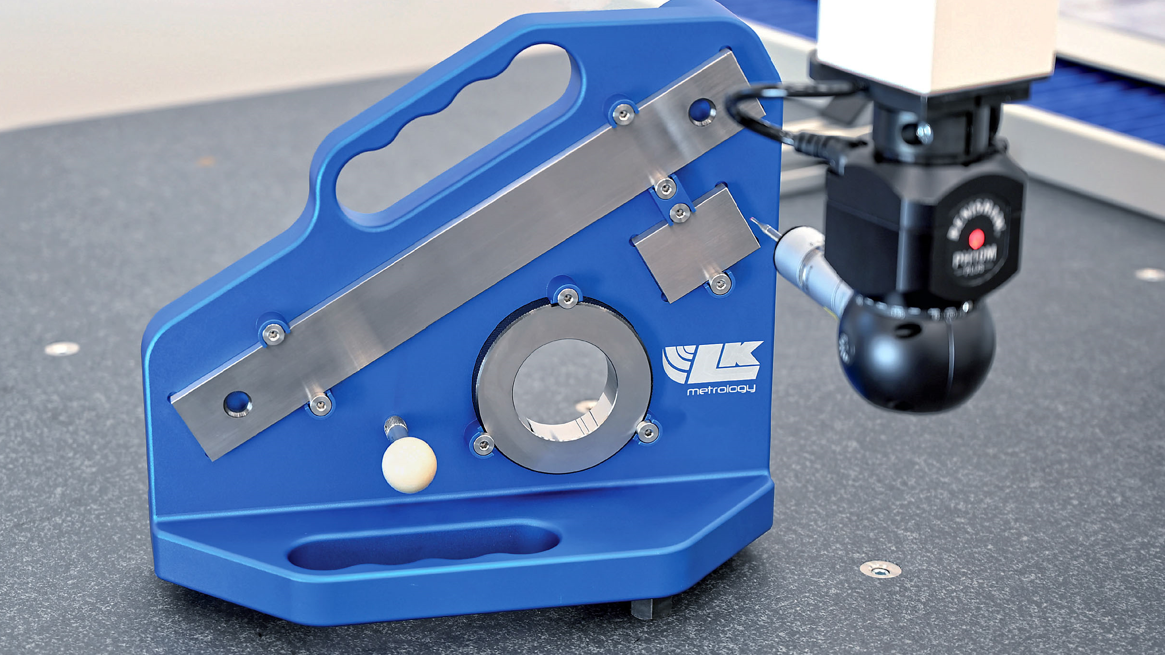
Координатты өлшеу машиналары (CMM) олар өлшемдік тексерудің алтын стандартын ұсынады. Бұл компьютерлік басқарылатын жүйелер сіздің бөлшектеріңіз бойынша нақты нүктелерді ұштық зондтармен өлшейді және нақты өлшемдерді CAD-спецификацияларымен салыстырады. Согласно MachineStation cMM өлшеуі қолмен әдістермен сенімді түрде анықтауға болмайтын допустималдықтарды растай алады, бұл CNC өңдеуінің уәде еткен пішін мен беттің жақсы жылтырылуының дәлдігін қамтамасыз етеді.
Беттің профилометриясы беттің тегістігін визуалды тексеруден аса дәлдікпен сандық бағалауға мүмкіндік береді. Стилус өңделген бет бойымен жылжып, Ra мәндері мен басқа да тегістік параметрлерін есептеу үшін шыңдар мен қазаншұңқырларды жазып алады. Бұл объективті өлшеу сіздің беттің сапасы бойынша берілген талаптардың орындалғанын растайды.
Өлшемдік растау құралдары күнделікті тексерулерді тиімді өткізуге арналған:
- Жедел өлшемдік нүктелік тексерулер үшін микрометрлер мен каліптер
- Жоғары көлемді өндірісте растау үшін «өтеді/өтпейді» калибрлері
- Ішкі диаметрді өлшеу үшін ішкі өлшегіштер
- Тік бағыттағы өлшемді растау үшін биіктік өлшегіштер
- Профиль мен контурды растау үшін оптикалық салыстырғыштар
Дәлдікпен жұмыс істеу үшін тараптар бұл әдістерді стратегиялық түрде қолданады. Бірінші үлгіні тексеру кезінде әрбір маңызды өлшемге қатысты толық координаталық өлшеуіш машина (CMM) арқылы тексеру жүргізілуі мүмкін, ал процесстің ішіндегі тексерулерде қалдықтар пайда болғанға дейін ауытқуларды анықтау үшін жылдам қолданылатын құралдар қолданылады.
Маңызды сапа сертификаттары
Сертификаттар тараптың жүйелі сапа басқаруға берілгенін көрсетеді. Алайда, осы сертификаттардың қайсысы сіздің қолданысыңыз үшін нақты маңызды? Machine Shop Directory деректеріне сәйкес, сертификаттар тек құжаттық сәйкестікті көрсетпейді: «Олар біз жасайтын әрбір бөлшекке деген жетілдікке берілгенін көрсетеді».
- ISO 9001: Әртүрлі салаларға қолданылатын негізгі сапа басқару стандарты. Құжатталған процедураларды, реттік аудиттерді және үнемі жақсарту талаптарын орнатады. Шамамен 67% OEM-дер өз тараптарынан осы сертификатты талап етеді.
- IATF 16949: Автомобиль өнеркәсібінің сапа стандарты, ISO 9001 негізінде құрылған, бірақ ақаулардың алдын алу мен жеткізушілер тізбегін басқару бойынша қосымша талаптары бар. Автомобиль компоненттерін шығаратын тараптар үшін міндетті.
- AS9100: Аэроғарыш және қорғаныс саласының сапа стандарты. Жалпы ISO талаптарынан басқа, ізденістілік, конфигурациялық басқару және қатер бағалауы бойынша қатаң талаптар қойылады.
- ISO 13485: Медициналық құралдарды өндірудің сапа стандарты, оның негізгі назары — құрылғының толық өмірлік циклы бойынша реттеуші талаптарға сәйкестік пен өнімнің қауіпсіздігіне аударылады.
CNC өңдеу қызметтерін (MW+ және оған ұқсас қызмет көрсетушілерді) бағалаған кезде, сертификатталған статус олардың сапа инфрақұрылымына салынған инвестициясын көрсетеді. Сертификатталған кәсіпорындар регулярлық бақылау аудиттерінен өтеді және әрбір үш жылда толық қайта сертификаттаудан өтеді, бұл сертификатталмаған өндірістерде болмайтын есеп беруге қабілеттілікті қамтамасыз етеді.
Қазіргі заманғы өңдеу кезіндегі статистикалық үдеріс бақылауы
Тараптар қанша мыңдаған бірдей бөлшектер бойынша тұрақтылықты қалай сақтайды? Статистикалық үдеріс басқаруы (SPC) осы сұраққа жауап береді. Салалық SPC бағдарламаларына сәйкес, бұл тәсіл сапа мәселелеріне айналмас бұрын аномалияларды анықтау үшін нақты уақыт режиміндегі өндіріс деректерін бақылайды.
SPC енгізуі бірнеше негізгі элементтен тұрады:
- Деректерді жинау: Өндіріс кезінде құралдың тозуы, кесу жылдамдығы, берілу жылдамдығы және өлшемдік дәлдік сияқты негізгі технологиялық параметрлерді бақылау
- Басқару диаграммасын құру: Негізгі айнымалылардың уақыт бойынша қалай өзгеретінін көрсететін көрнекі көрсеткіштерді құру, алдын ала белгіленген бақылау шектерімен қоса
- Аномалияларды анықтау: Бақылау шектерінен шығатын деректер нүктелерін анықтау үшін бақылау карталарын үздіксіз бақылау, бұл процестің тұрақсыздығын көрсетеді
- Түбірлік себептерді зерттеу: Аномалиялар пайда болған кезде жабдықтың жағдайын, технологиялық параметрлерді және материалдың күйін талдау
- Түзету шаралары: Сапасы төмен бұйымдар пайда болмас бұрын параметрлерді реттеу, орнатуларды оптимизациялау немесе құралдарды ауыстыру
Практикалық пайдасы қандай? Статистикалық процесті бақылау (SPC) өлшемдік ауытқуларды, құралдың тозу заңдылықтарын және процестің ауытқуларын тауып, олардың шектен тыс бұйымдарды өндіруге әкелуінен бұрын ұстайды. Соңғы бақылау кезінде проблемаларды анықтауға қарағанда, өндірушілер оларды өндіріс кезінде алдын ала болдырмақшы. Бұл үздіксіз бақылау мүмкіндігі сапасы тұрақты болатын тұтынушыларды, соңғы кезде жақсы бұйымдарды жаманнан ажыратуға сүйенетін тұтынушылардан ажыратады.
Сапа жүйелері мен бақылау мүмкіндіктері сіздің өңделген бөлшектеріңіз өзінің соңғы қолданысында қалай жұмыс істеуі керек екенін тікелей анықтайды. Қолданыстар туралы айтқанда, әртүрлі салалардың осы мүмкіндіктерді қалай пайдаланатынын түсіну сіздің нақты саланыз үшін ненің маңызы зор екенін көрсетеді.
Өңделген металдық бөлшектердің салалық қолданыстары
Сіз өңдеу процестері, материалдар, дәлдік шектері және сапа жүйелері туралы таныстыңыз. Бірақ барлық бұл қандай да бір нақты өнімдерге қалай айналады? Салалық талаптарды түсіну белгілі бір техникалық сипаттамалардың неге маңызды екенін көрсетеді және тұтынушылармен тиімдірек қарым-қатынас жасауға көмектеседі. Әрбір сала өзіндік талаптарын әкеледі, олар материалдың таңдалуын, дәлдік талаптарын және сертификаттау қажеттіліктерін анықтайды.
Автомобиль компоненттері мен шасси жинақтары
Автомобильдың өндірісі басқа салаларға қарағанда көбірек токарьланған металл бөлшектерін тұтынады. Қозғалтқыш блоктарынан бастап ілініс компоненттеріне дейін, дәлдікпен орындалған CNC-токарьлау қазіргі заманғы көліктердің талап ететін өлшемдік дәлдігі мен беттің сапасын қамтамасыз етеді.
MFG Solution дерегіне сәйкес, автомобильдерде CNC-токарьлау қолданысы қозғалтқыш компоненттеріне — иілген валдарға, камертонды валдарға және цилиндр басына, сонымен қатар беріліс қорабы бөлшектеріне — тісті доңғалақтарға, валдарға және корпусларға қатысты. Шасси мен ілініс элементтері — мысалы, басқару рычагтары, кронштейндер және дәлдікпен жасалған бушингтер — көліктің қауіпсіз жұмыс істеуі үшін әсіресе аз шекті ауытқуларды талап етеді.
Типтік автомобильдік токарьлау сипаттамаларына мыналар жатады:
- Қозғалтқыш пен трансмиссия компоненттері: Айналмалы құрылымдар үшін ±0,005 мм-ге дейінгі шекті ауытқулар
- Бетінің өңделу сапасы талаптары: Үйкелісті және тозуды азайту үшін қозғалмалы бөлшектер үшін Ra < 0,8 мкм
- Дөңгелектік пен концентриялық бақылау: Айналмалы валдар мен дәлдікпен жасалған тісті доңғалақтар үшін маңызды
- Кемпірқосақсыз токарьлау: Қауіпсіздікке қатысты маңызды бөлшектер үшін маңызды, себебі бұл бөлшектерде қалдықтар ақауларға әкелуі мүмкін
Автомобильдік қолданыста материалды таңдау өнімділікті және құнын теңестіреді. 42CrMo4 сияқты қоспалы болаттар жоғары беріктікті валдар мен тісті берілістерге арналған, ал 6061, 7075 және 2024 маркалы алюминий қоспалары қозғалтқыш пен шасси компоненттерінің салмағын азайтады. PEEK және PA66 сияқты инженерлік пластмассалар әртүрлі тозуға төзімді втулкалар мен изоляторларда барынша кеңінен қолданылады.
Автомобильдік OEM-дер мен деңгейлік қолданушыларға қызмет көрсететін тәрбиешілер үшін IATF 16949 сертификатына ие болу міндетті талапқа айналады. Бұл сапа стандарты автомобиль өндірушілерінің талап ететін жүйелі ақауларды болдырмау және жабдықтау тізбегін басқару қабілетін қамтамасыз етеді. Мысалы, Shaoyi Metal Technology автомобильдік жабдықтау тізбегіне қызмет көрсету мақсатында IATF 16949 сертификатын сақтайды, олар шасси жинақтары мен қосымша металдық втулкаларды дәлдікпен CNC өңдеу қызметін ұсынады және салада талап етілетін сапа туралы құжаттаманы ұсынады. Олардың жедел прототиптеуден массалық өндіріске дейін масштабтау мүмкіндігі мен бір жұмыс күні ішінде жеткізу мерзімі автомобиль саласының жылдамдық пен тұрақтылық қажеттілігін қанағаттандырады.
Әуе және қорғаныс салалары
Компоненттер 35 000 фут биіктікте немесе шайқастық жағдайларда қатесіз жұмыс істеуі керек болған кезде, аэроғарыштық CNC өңдеу стандарттары көптеген салалардың дәлдік деп қабылдайтын деңгейінен асады. Себебі, осындай жағдайларда компромисс жасауға болмайды.
Аэроғарыштық қолданыстар әртүрлі себептермен ерекше дәлдікті талап етеді:
- Қалыптық компоненттер: Қанат қосымшалары, фюзеляж рамалары және шасси бөлшектері — олардың ақауы адам өміріне қауіп төндіреді
- Қозғалтқыш қосымшалары: Турбина бөлшектері — экстремалды температурада және айналу жылдамдығында жұмыс істейді
- Ұшу басқару элементтері: Актуатор корпусы мен байланыс элементтері — олардың дәлдігі ұшақтың басқарылуына әсер етеді
- Жер серігі мен ғарыш кемелерінің бөлшектері: Ұшыру кезіндегі кернеулер мен ғарыш ортасында тіршілік ете алатын компоненттер
Титаннан CNC өңдеу аэроғарыштық қолданыстарда басымдылыққа ие болды, себебі бұл металл өте жоғары беріктік-салмақ қатынасы мен коррозияға төзімділігімен ерекшеленеді. Титанның өңделуі қиын болғандықтан, арнайы құрал-жабдықтар мен баяу кесу жылдамдығы қажет болады; бірақ ұшуға маңызды бөлшектер үшін оның өнімділік артықшылықтары қосымша шығындарды оправданады.
Титанға қарағанда арзан болатын, бірақ коррозияға төзімділік қажет ететін әуе-ғарыш саласына арналған қолданбалар үшін шойынсыз болаттан CNC өңдеу қолданылады. 17-4PH сияқты маркалар конструкциялық қосылыстар мен бекіткіштер үшін жоғары беріктік пен өте жақсы ортаға төзімділікті қамтамасыз етеді.
Сәйкес BPRHub aS9100D сертификаты әуе-ғарыш саласындағы сапа басқару жүйелері үшін алтын стандарт болып табылады. Бұл стандарт ISO 9001 талаптарын қамтиды және операциялық рисктерді басқару, конфигурацияны басқару мен жалған бөлшектердің пайда болуын болдырмау сияқты әуе-ғарыш саласына тән қосымша талаптарды енгізеді. Boeing, Airbus және қорғаныс саласындағы келісімшарттық компаниялар сияқты ірі өндірушілер AS9100 сәйкестігін іс-әрекет жасаудың шарты ретінде талап етеді.
Әуе-ғарыш саласындағы өңдеуде конфигурацияны басқаруға ерекше назар аударылады. Әрбір компонент құрамындағы шикізаттан соңғы жеткізу кезеңіне дейін толық іздегіштікке ие болуы тиіс, бұл қауіпсіздік мәселелері туындаған жағдайда жедел реакция беруге мүмкіндік береді. Бұл құжаттамалау қосымша шығындарға әкеледі, бірақ ұшуға маңызды қолданбалар үшін қажетті жауапкершілікті қамтамасыз етеді.
Тибіbetтік аппараттарды өндіру шарттары
Медициналық өңдеу, әдетте, кез келген саладан гөрі ең қатаң сапа талаптарында жұмыс істейді. Компоненттер адам денесінің ішіне орналасқан немесе өмір үшін маңызды процедураны қолдаған кезде, қателерге ешқандай рұқсат берілмейді.
PTSMAKE компаниясының айтуынша, медициналық CNC өңдеу басқа салалардан негізінен өте жоғары дәлдік талаптарымен, биологиялық үйлесімділігі бар материалдарды таңдаумен, қатаң реттеуші сақталаумен және толық құжаттама протоколдарымен ерекшеленеді. Бірнеше микрометрлік ауытқулар да сәтті емдеу мен науқасқа зиян келтіру арасындағы айырмашылықты құрайды.
Медициналық қолданыстар әртүрлі талаптарға ие болатын бірнеше санатқа бөлінеді:
- Имплантацияланатын құрылғылар: Ортопедиялық импланттар, жүрек қағысын реттегіш компоненттері және тіс конструкциялары — Ra мәндері 0,1–0,4 мкм аралығында және абсолютті биологиялық үйлесімділік талап етіледі
- Хирургиялық құралдар: Скальпельдер, пинцеттер және арнайы құралдар — қаттылық, тозуға төзімділік және тазалануға ыңғайлылық талап етіледі
- Диагностикалық жабдықтар: Кескіндеу және талдау жүйелері үшін дәлдікке негізделген корпус және механикалық жинақтар
- Дәрі-дәрмектерді енгізу жүйелері: Сығылғыш сұйықтармен жұмыс істейтін компоненттер, мұнда беттің тегіс болуы стерильділік пен ластану қаупін әсер етеді
Титанның биоүйлесімділігі мен остеоинтеграциялық қасиеттеріне байланысты имплантацияланатын құрылғылар өндірісінде титанның арнайы бөлшектері басым. Материалдың тірі сүйек тінімен байланысу қабілеті оны ортопедиялық қолдану үшін алмастырылмайтын етеді. Тот баспайтын болаттан жасалған бөлшектер өндірушілері коррозияға төзімділікті және зарарсыздандыру үйлесімділігін қажет ететін медициналық қолдануларды, әсіресе 316L сияқты маркалы хирургиялық құралдарды ұсынады.
Алюминий бөлшектерін өндіру салмағын азайту маңызды болған кезде медициналық құрылғылардың корпусы мен имплантацияланбайтын компоненттерін шығаруға бағытталған, биологиялық үйлесімділік талаптары болмаған жағдайда.
ISO 13485 сертификаты нақты медициналық құралдарды өндіру сапасы талаптарын қамтиды. Саладағы стандарттарға сәйкес, бұл сертификат тұтынушылардың өнімнің толық өмірлік циклы бойынша дизайн бақылауын, қауіптерді басқаруды және реттеуші сәйкестікті қамтитын күшті сапа басқару жүйелерін ұстап отыруын қамтамасыз етеді. FDA-ға тіркелу АҚШ-тағы медициналық нарыққа қызмет көрсететін тұтынушылар үшін қосымша талаптарды қосады, оларға толық құжаттама мен процестерді растау кіреді.
Медициналық қолданыстағы беттің жабылу талаптары эстетикалық әсерден асады. Тегіс беттер имплантаттарда бактериялардың адгезиясы мен биопленканың түзілуін болдырмауға көмектеседі. Хирургиялық құралдар үшін дұрыс жабылу оларды пайдаланудан кейін толық стерилизациялануын қамтамасыз етеді. Медициналық компоненттердің бетінің Ra мәні әдетте олардың нақты қолданылуы мен пациентпен қатынасу деңгейіне байланысты 0,1–1,6 мкм аралығында болады.
Бұл салалық нақты талаптарды түсіну сізге бөлшектерді дұрыс көрсетуге және жеткізушілердің мүмкіндіктерін нақты бағалауға көмектеседі. Алайда, өңделген бөлшектер күткен деңгейге жетпеген жағдайда не болады? Жиі кездесетін қиындықтарды анықтау уақыт, ақша және қатты қиналуларды үнемдейді.
Кеңістіктегі қиындықтарды анықтау және шешу
Сіздің бөлшектеріңіз келді, бірақ бірдеңе дұрыс емес. Мүмкін, беттің жағдайы қатты немесе өлшемдер шамадан тыс ауытқыған, немесе жиектерде керексіз қырлар пайда болған. Жеткізушіңізге бірден кінәлауға ұмтылмас бұрын, осы ақаулардың себептерін түсіну сізге проблеманың өңдеу процесінде, құрал-жабдықтарды таңдауда немесе бастапқы дизайнда жатқанын анықтауға көмектеседі. Металл бөлшектерді өңдеу кезінде тәжірибелі цехтар да жүйелі анықтау қажет ететін қиындықтарға тап болады.
Бетінің өңделуіндегі ақауларды шешу
Беттің жағындағы ақаулар бірден пайда болады: бет бұзылып, толқынды немесе сызылған болып көрінеді, ал сіз көрсеткендей — беттің біркелкі тегіс болуы керек. XC Machining компаниясының айтуынша, беттің жағындағы ақауларды олар пайда болған жерінде шешу — полировка немесе өңдеу сияқты қосымша процестерді болдырмауға мүмкіндік береді, нәтижесінде уақыт пен құн да үнемделеді.
Жиі кездесетін беттің жағындағы ақаулар мен олардың шешімдері:
- Тербеліс іздері: Кесу кезінде тербеліс нәтижесінде пайда болатын толқынды өрнектер. Шешімдер: айналу жиілігін төмендету, қажетті стружка жүктемесін сақтау үшін подача жылдамдығын арттыру, құрал ұстағышының дұрыс отырғызылуын тексеру, станоктың қаттылығын бағалау. Тұрақты тербелісті (чATTER) жою үшін анти-тербелісті құрал ұстағыштары немесе сіңірілетін жүйелер қолданылады.
- Құралдың іздері: Дұрыс емес подача жылдамдығы немесе тозған құралдар нәтижесінде көрінетін кесу өрнектері. Жабдықтау өтісінде подача жылдамдығын төмендетіңіз, материалға сай геометриялық параметрлері бар және өткір құралдарды қолданыңыз, сонымен қатар кесу аймағына жеткілікті суытқыш ағысын қамтамасыз етіңіз.
- Сызықтар мен қатты сызықтар: Жиі қиықтарды қайта кесу немесе қиықтарды жеткілікті шығармау салдарынан пайда болады. Қиықтарды шаю үшін суытқыштың берілуін жақсартыңыз, әртүрлі құралдың қозғалыс траекториясын қолдануды қарастырыңыз және ойық санының өңделетін материал талаптарына сәйкес келетінін тексеріңіз.
Мыс немесе басқа жұмсақ металдарды (мысалы, өңдеуге ыңғайлы мыс қорытпаларын) өңдеген кезде беттің жағымсыз сапасы жиі қию құралдарында қалыптасқан қабаттан туындайды. Беттің сапасын нашарлататын материалдың құралға жабысуын болдырмау үшін жоғары қию жылдамдығын және өткір құрал геометриясын қолданыңыз.
Өлшемдік дәлдік мәселелеріне шешім табу
Өлшемдік қателер жинақтау ақауларына және қабылданбаған бөлшектерге әкеледі. Согласно Exact Machine Service , жаман беттің сапасы мен өлшемдік дәлсіздіктері жиі бірдей себептерден туындайды: осьтің айналуындағы ауытқу, құралдың айналуындағы ауытқу және дұрыс емес қию параметрлері.
Төменде кеңістіктік қателерді анықтау мен түзетудің негізгі әдістері келтірілген:
- Өлшемдердің ауытқуы: Бөлшектер шығару кезінде біртіндеп толеранциядан шығады. Бұл әдетте машина қызған кезде жылулық кеңеюді немесе құралдың біртіндеп тозуын көрсетеді. Шешімдерге машинаға жеткілікті қызу уақыты беру, өңдеу процесінің ішінде өлшеу жүргізу және өлшемдерге әсер етпейтіндей құрал ауыстыру кестесін құру кіреді.
- Артық өңделген немесе жеткіліксіз өңделген элементтер: Бөлшектер берілген өлшемдерден үлкен немесе кіші болып өңделеді. Саладағы ақауларды анықтау бойынша нұсқаулықтарға сәйкес, олардың себептеріне құралдың иілуі, құралдың дұрыс емес орын ауыстыруы және бағдарламалау қателері жатады. Өңдеуден бұрын бағдарламаларды тексеріңіз, мүмкін болса, сынақ қиып алуларды орындаңыз және құралдың диаметрін компенсациялау параметрлерін растаңыз.
- Дөңгелек емес тесіктер: Осьтер бойынша әртүрлі өлшемдер көрсететін дөңгелек элементтер. Бұл әдетте құралдың иілуі, машина артқы сайығы немесе жеткіліксіз беріліс пен айналу жылдамдығынан пайда болады. Тесіктердің нақты диаметрлері үшін борлау операциялары тесіктердің дөңгелектігін қашанда да тесу немесе интерполяцияға қарағанда жақсы қамтамасыз етеді.
Балқытылған болат пен басқа қатты материалдарды өңдеу кезінде құралдың иілуі ерекше мәселеге айналады. Ұзын құралдар кесу күштері әсерінен көбірек иіледі, нәтижесінде детальдар орындарынан ығысады. Мүмкіндігінше қысқа құрал ұзындығын пайдалану және кесу тереңдігін азайту иілу әсерлерін азайтады.
Құралдың тозуын басқару және оның әсерлері
Әрбір кесу құралы соңында тозады, бірақ уақытынан бұрын тозу шығындарды көтереді және сапаны нашарлатады. Согласно CNC пісірме кітабы , айналу жиілігін тым жоғары орнату артық жылуға әкеледі, бұл кесу құралдарын жұмсартып, оларды тез кемітеді, ал өте баяу берілу құралдарды дәл соншалықты тез жойып жіберетін үйкеліске әкеледі.
Жиі кездесетін құралға байланысты мәселелер мен олардың шешімдері:
- Тез құрал тозуы: Материал үшін кесу жылдамдығы тым жоғары, жеткіліксіз суыту сұйығы немесе құралдың қаптамасын таңдау қатесі. Беттік жылдамдықтарды өндірушінің ұсыныстарымен сәйкестендіріңіз, суыту сұйығының кесу аймағына жететінін қамтамасыз етіңіз және өңделетін бұйым материалына сай қаптамаларды таңдаңыз.
- Құралдың сынғаны: Артық кесу жүктемесі, фрезаның ойықтарында ұнтақтың жиналуы немесе материалда кенеттен кездесетін қатты аймақтар. Беріліс жылдамдығын төмендетіңіз, ұнтақты шығару үшін сәйкес ойық санын қолданыңыз және материалдың біртектілігін тексеріңіз. Өңдеу саласының сарапшыларының пікірінше, бастапқы өңдеушілер кесу күштерінің артық болуына қарағанда, ұнтақты шығару мәселелерінен көбірек құралдарды сындырады.
- Ширақ пайда болуы: Сипаттамалардың шеттерінде сүйір, керексіз шығыңқылықтар. Себептері: тупталған құралдар, артық беріліс жылдамдығы және материалға сай емес құрал геометриясы. Шешімдері: сүйір құралдарды қолдану, кесу параметрлерін оптималдау және сәйкес құрал геометриясын таңдау. Мыс, нейлон және басқа да жұмсақ материалдарды өңдеген кезде қиындықтардың алдын алу үшін ерекше сүйір құралдар мен бақыланатын шығу стратегиялары қажет.
Мәселелер дизайн мәселелерін көрсеткен кезде
Кейде өңдеу қиындықтары бөлшек дизайнына, яғни өңдеу процесіне қарағанда, байланысты болады. Төмендегі жағдайларда дизайн өзгерістерін қарастырыңыз:
- Тұрақты жұқа қабырғалы деформация: Қию күштері әсерінен 1 мм-ден жұқа металл қабырғалары көбінесе өңдеу стратегиясына қарамастан иіледі. Қабырға қалыңдығын арттыру немесе қолдау құрылымдарын қайта жобалау — бұл мәселені шешудің жалғыз шарты болуы мүмкін.
- Қол жетпейтін элементтер: Өте ұзын құралдарды талап ететін терең қуыстар немесе ішкі элементтер әрқашан иілу мен тербеліске ұшырау қаупін туғызады. Қатысуға қол жеткізу жолдарын қайта жобалау немесе бөлшекті бөлу — физиканы жеңуге қарағанда нәтижелірек болуы мүмкін.
- Допусктардың жиналуына байланысты ақаулар: Жеке элементтер дұрыс өлшенгеніне қарамастан, жиналған бөлшектер сыймайды — бұл жағдайда өңдеуді қатаңдауға қарағанда допусктарды қайта бөлу қажет.
Тәжірибелі тараптар DFM-ті қарастыру кезінде осы дизайнға негізделген мәселелерді анықтайды. Егер әртүрлі құралдар мен параметрлермен жүргізілетін бірнеше өндірістік циклдар бойынша мәселелер қайталанып отырса, онда түбірлік себеп өңдеу орындалуында емес, скорее барлығы дизайндық талаптарда жатады.
Бұл негізгі тұжырымдамаларды түсіну сізге тараптармен тиімдірек қарым-қатынас жасауға және түзетуші іс-шаралар туралы дұрыс шешім қабылдауға көмектеседі. Жиі кездесетін қиындықтар шешілгеннен кейін соңғы қадам — сіздің нақты қолданылу талаптарыңызға сәйкес тұрақты сапа көрсететін өңдеу серіктесін таңдау.
Дұрыс метал өңдеу серіктесін таңдау
Сіз техникалық білімді меңгердіңіз: өңдеу процестері, материалдар, дәлдік шектері, құны және сапа жүйелері. Енді осы білім сәтті бөлшектерге айналуын немесе айналмауын анықтайтын шешім қабылдау кезеңі келді. Өңдеу серіктесін таңдау — тек ең төмен баға ұсынатын тарапты іздеу емес. Бұл — сіздің жоба талаптарыңызға сәйкес келетін мүмкіндіктері, сапа инфрақұрылымы мен қызмет көрсету философиясы бар тарапты анықтау. Сіз маңыңыздағы CNC өңдеу цехтарын іздеуде болсаңыз немесе шетелдік тараптарды бағалайтын болсаңыз, бағалау критерийлері бірдей қолданылады.
Өңдеу қызметінің мүмкіндіктерін бағалау
3ERP-тің айтуынша, CNC өңдеу қызметі қолындағы құралдардың тиімділігіне тең. Бірақ жабдықтар тек бастапқы нүкте болып табылады. Толық құрамдағы тәжірибелі тәртіптерді бағалау үшін бірнеше бағытты қарастыру қажет:
- Сертификаттар: Сапа сертификаттары тұрақтылыққа жүйелі түрде ұмтылу туралы куәлік береді. ISO 9001 — сапаны басқарудың негізгі стандарты болып табылады, оны OEM-дердің 67%-ы өз тәжірибелерінен талап етеді. Салалық сертификаттар одан да маңызды: автомобиль өнеркәсібі үшін IATF 16949, әуе-ғарыш саласы үшін AS9100, медициналық қолданыстар үшін ISO 13485. Бұлар тек қағаз құжаттар емес — бұл рәсмі талдауға ұшыраған, құжатталған процедуралар мен үнемі жақсарту талаптары бар сапа жүйелері.
- Жабдық мүмкіндіктері: Қолжетімді станоктардың диапазонын тексеріңіз. Цехта 3 осьті, 4 осьті және 5 осьті фрезерлеу орталықтары бар ма? Токарьлық мүмкіндіктер қандай? Салалық сарапшылардың айтуынша, әртүрлі және жоғары технологиялық станоктары бар қызмет көрсетуші әртүрлі жобаларды орындай алады және қарапайым цехтардың қол жеткізе алмайтын алдыңғы қатарлы әдістерді қолдана алады.
- Материалдар бойынша білім: Менің жақын аумағымда немесе басқа жерлерде орналасқан барлық механикалық өңдеу цехтары әртүрлі материалдармен жұмыс істемейді. Кейбіреулері алюминиймен, ал басқалары — штампталған болат пен титанмен жұмыс істеуге маманданған. Сіздің қажетті материалдарыңызды оңай таба алатынын сұраңыз — материалдарды табудағы кешігулер жеткізу мерзімдерін ұзақтырады және өндіріс шығындарын көтереді.
- Дайындалу уақытының икемділігі: Типтік жеткізу мерзімдерін түсіну өте маңызды. Ұзақ мерзімді кешігулер жобаларды тоқтатады және қаржылық шығындарға әкеледі. Мерзімі қысқа болған жағдайларда жылдам қызмет көрсететін тұтынушыларды іздеңіз. Кейбір сертификатталған өндірушілер 3 жұмыс күнінен бастап жеткізу мерзімдерін ұсынса, басқалары өте қажетті жағдайлар үшін күн ішінде жеткізу опцияларын береді.
- Сапа жүйелері: Сертификаттардан басқа, нақты сапа бақылау тәжірибелерін зерттеңіз. Олар бірінші үлгіні тексереді ме? Өндіріс процесінің қай кезеңінде тексерулер жүргізіледі? Өлшемдік ауытқуларды қалдық пайда болғанға дейін анықтау үшін Статистикалық өндіріс бақылауы (SPC) қолданылады ма? Терең сапа бақылау шараларына өндіріс кезінде реде жүргізілетін тексерулер, жеткізуге дейінгі соңғы тексеру және кез келген қателерді түзетуге арналған саясаттар кіреді.
Потенциалды серіктестерді бағалаған кезде, олардың портфолиосын немесе жағдайлар бойынша зерттеулерін көрсетуді сұраңыз. Өткен жобалар компанияның қабілеттерін, клиент түрлерін және орындай алатын жұмыстардың күрделілігін көрсетеді. Бір механикалық өңдеу саласының сарапшысы атап өткендей, тәжірибе — бұл сараптама; әрбір жоба компанияға қателіктердің пайда болу ықтималдығын азайтатын және процестердің тегіс өтуін қамтамасыз ететін білім мен дағдыларды қосымша береді.
Прототиптен өндірістік серіктестікке дейін
Көптеген сатып алушылар қарамайтын маңызды көрініс: сіздің бөлшектеріңіздің прототипін жасайтын тағамдық құрама өндіріс көлемі үшін идеалды болмауы мүмкін, және керісінше. Согласно UPTIVE , прототиптеу — бұл идеяларды пішіндеу, жетілдіру және толық масштабты өндіріске кірісу алдында растау үшін маңызды сынақ кезеңі.
Неге өндіріске кірісу алдында CNC прототиптеу маңызды? Бірнеше себеп басымдыққа ие:
- Дизайнды растау: Физикалық прототиптер CAD модельдерінде жасырын қалған мәселелерді ашады. Дәл келуі, қызмет етуі және жиналуы сияқты мәселелер тек нақты бөлшекті ұстаған кезде ғана айқын байқалады.
- Процесті тексеру: Прототиптау сіздің дизайндыңыз тұрақты түрде шығарылуы мүмкін екенін растайды. Құралдарға қатынас, бекіткіштердің стратегиясы немесе материалдың әрекеті бойынша мәселелер бастапқы өндіріс кезінде анықталады.
- Құнын нақтылау: Прототиптардан алынған нақты фрезерлеу уақыты деректері бағаланған цикл уақытын алмастырады, ол өндірістік құнын нақтырақ есептеуге мүмкіндік береді.
- Тараптарды бағалау: Прототиптық жасақтар сізге ірі тапсырыстарға өтуге дейін қарым-қатынас, сапа және жеткізу көрсеткіштерін бағалауға мүмкіндік береді.
Жедел прототиптау компаниялары мен өндірістік серіктестерді салыстырғанда, олардың қызмет көрсету мүмкіндіктерін, сенімділігін, масштабталу қабілетін және сіздің өнім түріңізді өңдеудегі мамандығын ескеріңіз. Салалық нұсқауларға сәйкес, тиісті тәжірибеге ие серіктесті таңдау олардың кеңінен таралған қателерді және олардан қалай айналып өтуге болатынын жақсы білуі салдарынан ондаған мың доллар үнемдеуге мүмкіндік береді.
Ең жақсы серіктестіктер прототиптеуға икемділікті өндірістің масштабталуымен ұштастырады. Прототип сатысында Өндіріске Қолайлы Дизайн (DFM) бойынша кеңес беретін тәрбиешілерді іздеңіз. Бұл кеңестер өндірістік құрал-жабдықтарды дайындамас бұрын дизайндарды жетілдіруге көмектеседі, соның арқасында кейінірек қымбат тұратын өзгерістерден сақтануға болады. Бұл қолдауды ұсынатын тәрбиешілер сіздің жобаңыздың сәттілігіне ғана емес, сонымен қатар тапсырыстарды орындауға ғана емес, қосымша инвестициялар жасайды.
Металл бөлшектеріңіз бойынша жобаңызды бастау
Әрі қарай жылжуға дайынсыз ба? Машинамен өңдеу серіктесімен ынтымақтастық орнату үшін тәжірибелік бағдарлама:
1-қадам: Құжаттарыңызды дайындаңыз. CAD файлдарын (STEP немесе IGES пішімдері әмбебап болып табылады), маңызды сипаттамалар үшін Геометриялық өлшемдер мен Толеранциялар (GD&T) белгілері бар 2D сызбаларды, материалдың сипаттамаларын, санын және жеткізу мерзімін жинаңыз. Сіздің сұранысыңыз неғұрлым толық болса, сонша дәл сметалар аласыз.
2-қадам: Бірнеше көзден смета сұраңыз. Жергілікті станок цехтарын немесе халықаралық тәжірибелік тұтынушыларды зерттеу арқылы бәсекелестік бағалар алыңыз. Бірлік бағасынан тыс — жеткізу мерзімдерін, жеткізу құнын, қосымша қосылған бақылау есептерін және төлем шарттарын бағалаңыз.
3-қадам: Әңгіме арқылы қабілеттерді растаңыз. Электрондық пошта арқылы жіберілген бағалар тек қана бір бөлігін ғана көрсетеді. Телефон немесе бейнеконференциялық шақырулар сізге қарым-қатынасқа жауап беру қабілетін, техникалық түсініктілікті және сіздің сұрақтарыңызға жауап беруге дайындықты көрсетеді. Өндіріс саласының сарапшыларының пікірінше, қарым-қатынас кез келген сәтті серіктестіктің негізі болып табылады.
4-қадам: Тәжірибелік үлгілердің санынан бастаңыз. Өндіріс көлеміне өтуге дейін тұтынушының сапасы мен қызметін кішірек тапсырыстар арқылы растаңыз. Бұл төмен қауіпті тәсіл сіз үлкен инвестициялар жасағаннан бұрын қабілеттерді растайды.
5-қадам: Сапа күтімдерін алдын ала орнатыңыз. Өндіріс басталғаннан бұрын бақылау талаптарын, құжаттама талаптарын және қабылдау критерийлерін көрсетіңіз. Айқын күтімдер талас туғызбайды және бөлшектердің сіздің стандарттарыңызға сай болуын қамтамасыз етеді.
Сенімді өндірістік шешімдер іздейтін оқырмандар үшін жедел прототиптеуден массалық өндіріске дейін масштабталатын қызмет көрсететін компания — бағалануға тұрған мықты нұсқа. Shaoyi Metal Technology олардың IATF 16949 сертификаты мен SPC сапасын бақылау жүйесі бұл нұсқаулықта талқыланған жүйелік сапа талаптарына сай келеді. Бір жұмыс күнінен бастап қысқа әзірлеу мерзімі мен автомобильдің шасси жинақтарын және қосымша металдық бұрандалы ілгектерді дәлдетіп өңдеуге арналған дәлдетілген CNC өңдеу мүмкіндіктері олардың жылдамдығы, сапа сертификаты мен масштабталу қабілетінің үйлесімін көрсетеді — бұл қатаң талаптар қойылатын жобалар үшін өте маңызды.
Сіз соңында машинашыны «маған жақын» орыннан таңдасаңыз да немесе шетелде орналасқан мамандандырылған өндірістік орынмен ынтымақтастыққа кірсеңіз де, бағалау критерийлері өзгеріссіз қалады. Сертификаттар сапаға берілген ұмтылысты растайды. Жабдықтар мүмкіндіктердің шегін анықтайды. Материалдар бойынша мамандық тұрақтылыққа әсер етеді. Әзірлеу мерзімін икемділігі жобаның сәтті аяқталуын қамтамасыз етеді. Ал сапа жүйелері әрбір бөлшектің техникалық талаптарға сай болуын қамтамасыз етеді.
Бұл нұсқаулықта сіз алған білім сізге дұрыс сұрақтар қоюға, бағаларды дәл түсінуге және ең төменгі бағаға ғана емес, құндылық ұсынатын серіктестерді таңдауға мүмкіндік береді. Сіздің келесі қадамыңыз? Білікті тараптарға хабарласыңыз, сөйлесуге кірісіңіз және өз дизайндарыңызды дәл металдық бөлшектерге айналдыруды бастаңыз.
Металл бөлшектерін өңдеу: Жиі қойылатын сұрақтар
1. Тетіктерді өңдеу қанша тұрады?
CNC өңдеу құны әдетте жабдықтың күрделілігі мен дәлдік талаптарына байланысты сағатына $50-ден $250-ге дейін болады. Бір ғана прототиптің құны құрама шығындардың жалпы құнның 60%-ын құрайтындықтан, $85-150 құрайды, ал 100 немесе одан да көп бөлшек шығару кезінде тұрақты шығындар көптеген бөлшектерге таратылады да, бір бөлшектің құны $8-20-ға дейін төмендейді. Негізгі құн факторларына материалдың таңдалуы, станокта өңдеу уақыты, дәлдік талаптары және жылумен өңдеу немесе беттің жабылуы сияқты қосымша операциялар жатады.
2. Металл бөлшектері қалай өңделеді?
Металл бөлшектері арнайы кесу құралдарын қолдана отырып, қатты металл жұмыс бөліктерінен материалды алып тастау арқылы субтрактивті өндіріс процестері арқылы өңделеді. Төрт негізгі процесс — бұл валдар мен втулкалар сияқты цилиндрлі бөлшектер үшін CNC-тің айналуы, жазық беттер мен күрделі контурлар үшін CNC-тің фрезерлеуі, тесіктерді жасау үшін бұрғылау және өте тар допусктер мен жоғары сапалы беттік жабынын алу үшін әйнекше өңдеу. Көп осьті CNC-машиналары жұмыс бөліктеріне шамамен кез келген бұрыштан тәжірибелік түрде жақындай алады, ол бір реттік орнату кезінде күрделі геометриялық пішіндерді жасауға мүмкіндік береді.
3. CNC өңделетін бөлшектер үшін қандай материалдар ең жақсы?
Материалды таңдау сіздің қолданылуыңызға қойылатын талаптарға байланысты. Алюминий 6061 жалпы қолданыстар үшін өте жақсы өңделу қасиетіне ие және төмен құнымен ерекшеленеді, ал 7075 — аэроғарыш саласына арналған беріктікке ие. Тұрақты токпен жұмыс істейтін болат 303 жоғары көлемді бекітпе бұрандаларын өңдеуге ыңғайлы, 304 — жалпы коррозияға төзімділік қасиетімен ерекшеленеді, ал 316L — теңіз және медициналық орталарда өте жақсы көрсеткіштер көрсетеді. Мыс C36000 электрлік және декоративті бөлшектер үшін өте жақсы өңделу қасиетіне ие. Титан өңдеу шығындары жоғары болғанымен, аэроғарыш саласы мен медициналық импланттар үшін өте жоғары беріктік-салмақ қатынасын қамтамасыз етеді.
4. CNC токарлау қандай дәлдіктерге қол жеткізе алады?
Стандарттық CNC өңдеу кезінде функциялық емес өлшемдер үшін ±0,10 мм, функционалдық элементтер үшін ±0,05 мм, ал дәл келетін қосылыстар үшін ±0,02 мм дәлдіктері қол жетімді. Аса дәл өңдеу кезінде маңызды интерфейстер үшін ±0,01 мм немесе одан да аз дәлдіктерге қол жеткізуге болады. Дегенмен, дәлдікті арттыру шығындарды қатты көтереді — дәлдікті ±0,10 мм-ден ±0,01 мм-ге дейін жоғарылату өңдеу шығындарын 200–400% арттыруы мүмкін. Тек қызметтік талаптардың қажет ететін жерлерінде — мысалы, роликті тірек орындарында, тығыздау беттерінде және орналасу элементтерінде — ғана жоғары дәлдіктерді қолданыңыз.
5. Металл өңдеу құрамында қандай сертификаттар болуы керек?
ISO 9001 – сапаны басқару бойынша негізгі халықаралық стандарт болып табылады, оны OEM-дердің 67%-ы талап етеді. Салалық сертификаттар арнайы қолданыстар үшін маңыздырақ болып келеді: автомобиль жабдықтаушылары үшін IATF 16949, аэроғарыш пен қорғаныс саласы үшін AS9100, медициналық құрылғылар шығару үшін ISO 13485 міндетті. Сертификатталған кәсіпорындар редовды аудиттерге ұшырайды және құжатталған процедураларды, жүйелі сапа бақылауын және үздіксіз жақсарту бағдарламаларын ұстанады, бұл бөлшектердің тұрақты сапасын қамтамасыз етеді.