 Piccole partite, alti standard. Il nostro servizio di prototipazione rapida rende la validazione più veloce e facile —
- Riduci i Costi di Estrusione dell'Alluminio con 5 Fondamentali Consigli DFM
- Il vero ROI degli stampi di estrusione personalizzati per la produzione di massa
- Prototipazione in Metallo per l'Automotive: Una Guida per un'Innovazione più Rapida
- Ricambi per Aria Condizionata Auto: Dal Compressore all'Evaporatore Svelati

Anatomia dello stampo progressivo per stampaggio: tutti i componenti che ogni ingegnere deve conoscere
Time : 2026-03-31
Che cos'è lo stampaggio con stampo progressivo e come funziona
Ti sei mai chiesto come i produttori realizzino migliaia di componenti metallici identici con notevole velocità e precisione? La risposta risiede in uno dei processi più efficienti della lavorazione dei metalli. Lo stampaggio a matrice progressiva è un metodo ad alta produttività per la formatura dei metalli in cui una striscia continua di materiale avanza attraverso più stazioni di lavoro all’interno di un’unica matrice, e ogni stazione esegue un’operazione specifica fino a quando il componente finito non emerge alla fine.
Stampaggio a stampo progressivo è una tecnica di lavorazione dei metalli in cui il foglio metallico avanza attraverso una sequenza di stazioni — ciascuna delle quali esegue operazioni come perforazione, taglio a contorno, formatura o coniazione — fino a quando il componente completato non viene separato dalla striscia portante in un’unica corsa di produzione continua.
Allora, cos'è esattamente uno stampo nella produzione? Immagina uno stampo come un utensile specializzato che modella o taglia un materiale sotto pressione. Nello stampaggio progressivo, lo stampo contiene più stazioni disposte in sequenza, ciascuna progettata per eseguire un’operazione precisa sulla striscia di metallo mentre questa avanza attraverso la pressa.
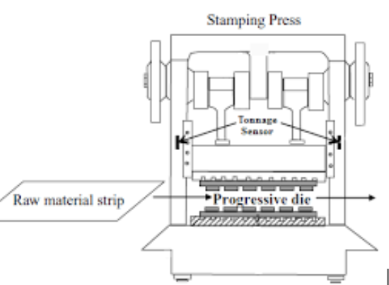
Come gli stampi progressivi trasformano il metallo grezzo in componenti di precisione
Immagina di inserire una striscia piana di metallo in una macchina e di vederla uscire già completamente formata e pronta all’uso — tutto in pochi secondi. Questa è la potenza della tecnologia degli stampi e dello stampaggio progressivo. Il processo ha inizio quando una bobina di lamiera viene alimentata nella pressa da stampaggio, dove incontra una serie di stazioni accuratamente progettate.
Ogni stazione svolge uno scopo specifico:
- Stazioni di foratura perforare fori e creare riferimenti di guida che orientano la striscia nelle operazioni successive
- Stazioni di tranciatura tagliare i profili esterni e separare il materiale
- Stazioni di formatura piegare e modellare il metallo in geometrie tridimensionali
- Stazioni di coniazione applicare l’ultima calibratura e le finiture superficiali per garantire tolleranze strette
La bellezza di questo sistema? Tutte le operazioni avvengono contemporaneamente in diverse sezioni della striscia. Mentre una sezione viene perforata, un'altra subisce la formatura e un'altra ancora riceve la coniazione finale: il tutto in un singolo colpo di pressa.
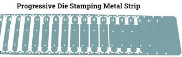
Il percorso stazione per stazione della lavorazione della striscia metallica
Durante la stampa progressiva, la striscia metallica avanza di una distanza precisa—denominata passo—ad ogni colpo di pressa. I meccanismi di alimentazione garantiscono un posizionamento costante, mentre i perni di centraggio allineano il materiale a ogni stazione per assicurare l’accuratezza dimensionale. Dopo la stampa, le piastre espulsori estraggono agevolmente i pezzi finiti, consentendo velocità di produzione che possono raggiungere centinaia o addirittura migliaia di pezzi all’ora.
Questa efficienza spiega perché l'approccio con matrici progressive domina la produzione su larga scala in settori critici. I produttori automobilistici fanno affidamento su matrici di stampaggio per supporti, connettori e componenti strutturali. I produttori di apparecchiature elettroniche le utilizzano per contatti di precisione e schermature. Le aziende produttrici di dispositivi medici ne dipendono per strumenti chirurgici e componenti di impianti, dove la costanza è un requisito imprescindibile.
Qual è il vantaggio fondamentale? La stampatura progressiva consente di integrare in un’unica operazione fluida ciò che altrimenti richiederebbe più macchine e diverse fasi di manipolazione. Secondo JVM Manufacturing, questa riduzione del numero di passaggi di lavorazione si traduce direttamente in una maggiore efficienza produttiva e in costi unitari inferiori su larga scala.
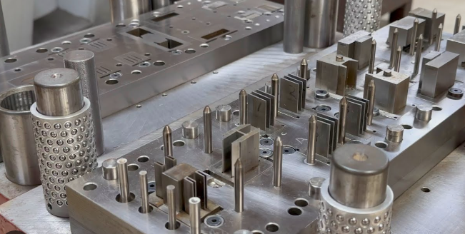
Anatomia di una matrice progressiva e componenti essenziali
Comprendere come una matrice progressiva raggiunga una precisione così straordinaria richiede di guardare al di sotto della superficie. Ogni matrice per imbutitura è un assemblaggio complesso in cui decine di componenti operano in sincronia; conoscere la funzione di ciascuna parte aiuta gli ingegneri a ottimizzare le prestazioni, risolvere i problemi e prolungare la vita utile dell’attrezzatura.
Immaginate una matrice progressiva come una macchina di precisione dotata di tre sistemi interconnessi: la struttura portante che assorbe le forze , i componenti operativi che modellano il metallo e i sistemi di guida che mantengono l’allineamento per milioni di cicli. Analizziamo ora ciascun elemento fondamentale.
Componenti dell’insieme superiore e inferiore della matrice
L’insieme della matrice costituisce la spina dorsale di ogni matrice per lamiera, fornendo la base rigida su cui vengono montati tutti gli altri componenti. Secondo Il Produttore , queste piastre devono essere lavorate con parallelismo e planarità entro tolleranze critiche: qualsiasi scostamento in questo ambito si ripercuote sull’intero utensile.
- Tavola superiore dello stampo: La piastra superiore che si fissa al traverso della pressa e supporta tutti i punzoni e i componenti di formatura montati nella parte superiore, spingendoli verso il basso ad ogni corsa
- Tavola inferiore dello stampo: La piastra di base fissata al piano della pressa, dotata di fori fresati o tagliati a fiamma che consentono ai trucioli e ai ritagli di cadere liberamente sul piano della pressa
- Piastra punzonatrice (di ritenzione): Una piastra temprata che posiziona con precisione e fissa i punzoni di taglio, spesso dotata di meccanismi a sfera bloccabile per un rapido accesso alla manutenzione
- - Il blocco a fusoliera: La sezione in acciaio temprato contenente i pulsanti di matrice: bocchette di precisione rettificate il cui profilo corrisponde a quello dei punzoni di taglio con un gioco calcolato
- Piastre di supporto: Piastrine temprate posizionate dietro i punzoni e i pulsanti di matrice per distribuire le forze concentrate e impedire danni alle più morbide scarpe di matrice
Lo spessore della piastra di supporto è direttamente correlato alle forze previste. Un’operazione di coniazione, che comprime il metallo tra le sezioni superiore e inferiore, richiede piastra di supporto sensibilmente più spesse rispetto a una semplice matrice per piegatura. La maggior parte delle piastre di supporto è realizzata in acciaio, anche se l’alluminio offre vantaggi per alcune applicazioni: pesa un terzo rispetto all’acciaio, viene lavorato rapidamente e assorbe efficacemente gli urti nelle operazioni di punzonatura.
Sistemi critici di allineamento e guida
La precisione delle matrici progressive dipende dal mantenimento di un allineamento perfetto tra le parti superiore e inferiore ad ogni corsa. Anche un minimo disallineamento causa interferenze tra punzone e matrice, usura accelerata e deriva dimensionale nei pezzi finiti.
- Perni guida e bocce: Componenti rettificati con precisione, realizzati con tolleranza di ±0,0001 pollici, che garantiscono l’allineamento delle piastre di supporto ad ogni corsa — disponibili nella versione a attrito (con boccole in bronzo-alluminio e tappi in grafite) o nella versione a rulli/sfere per velocità più elevate e separazione più agevole
- Blocchi di appoggio laterali (Heel Blocks): Blocchi in acciaio avvitati, inchiodati e spesso saldati su entrambe le ganasce, che assorbono la spinta laterale generata durante il taglio e la formatura—fondamentali quando le forze sono direzionali
- Centraggi: Perni di precisione che si inseriscono in fori precedentemente realizzati nella striscia, garantendo un posizionamento esatto in ogni stazione prima dell’inizio delle operazioni
- Guide per lo stoccaggio: Guide o canali che controllano la posizione laterale della striscia mentre questa avanza attraverso lo stampo, impedendo deviazioni che causerebbero condizioni di errato alimentazione
- Intagli di bypass: Ritagli posizionati strategicamente nella piastra espulsore che consentono alle caratteristiche precedentemente formate di passare attraverso le stazioni successive senza interferenze—essenziali quando operazioni precedenti creano geometrie rilevate che altrimenti entrerebbero in collisione con gli utensili a valle
La piastra di estrazione merita particolare attenzione tra i componenti degli stampi da punzonatura. Questa piastra caricata a molla circonda i punzoni di taglio ed estrae il materiale da essi durante la loro fase di ritrazione. Quando il metallo viene tagliato, tende naturalmente ad accartocciarsi intorno al corpo del punzone. In assenza di una forza di estrazione adeguata, i pezzi rimangono attaccati ai punzoni causando intasamenti o danneggiamenti.
In che modo questi componenti degli stampi progressivi lavorano insieme per mantenere la precisione su migliaia — o addirittura milioni — di colpi? La risposta risiede nella gestione distribuita del carico. I perni di guida mantengono l’allineamento generale tra le basette. I blocchi di appoggio assorbono la spinta laterale che altrimenti deformerebbe i perni di guida. I centraggi regolano con precisione la posizione della striscia in ogni stazione. Infine, la rigidità delle basette dello stampo, opportunamente dimensionate, ne impedisce la flessione sotto carico.
La qualità dei componenti determina direttamente le tolleranze raggiungibili. Secondo U-Need, perni di guida e boccole realizzati con finiture superficiali specchiate (Ra = 0,1 μm) mediante rettifica di precisione riducono drasticamente l’attrito e proteggono contro il grippaggio. Quando vengono mantenute tolleranze di ±0,001 mm sui componenti critici, l’intero sistema di stampo è in grado di garantire le dimensioni del pezzo con una precisione che strumenti meno sofisticati non possono assolutamente raggiungere.
Questa relazione tra precisione dei componenti e qualità del pezzo spiega perché gli ingegneri esperti specificano tolleranze più strette sui componenti degli stampi progressivi rispetto a quanto potrebbe sembrare necessario: l’effetto cumulativo di piccoli miglioramenti su decine di parti produce guadagni significativi nella coerenza del pezzo finito.
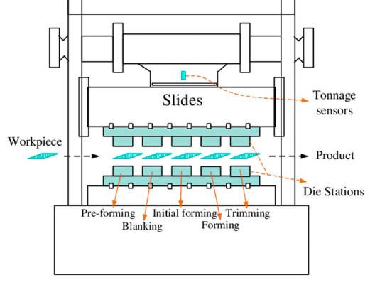
Sequenziamento delle stazioni e funzioni operative individuali
Ora che conoscete i componenti che costituiscono uno stampo progressivo, esploriamo ciò che effettivamente accade mentre il metallo transita attraverso ciascuna stazione. Immaginate una staffetta in cui ogni corridore svolge un compito specifico prima di passare il testimone: qui, però, il "testimone" è la vostra striscia di metallo e i "corridori" sono stazioni progettate con precisione che operano in perfetta coordinazione.
La sequenza riveste un'importanza fondamentale. Posizionare una stazione di formatura prima dell'operazione di punzonatura richiesta comporterebbe danni agli utensili. Collocare una stazione di calibratura troppo presto provocherebbe distorsioni sulle superfici accuratamente finite nelle operazioni successive. Gli ingegneri dedicano molto tempo all'ottimizzazione del processo dello stampo per bilanciare qualità del pezzo, durata degli utensili ed efficienza produttiva.
Funzioni della stazione di punzonatura e taglio
Il processo di stampaggio con matrice progressiva inizia tipicamente con operazioni che rimuovono materiale — creando fori, fessure e profili che definiscono la geometria del componente. Queste stazioni sottrattive costituiscono la base su cui si basano tutte le operazioni successive.
Stazioni di foratura eseguono il lavoro iniziale sulla striscia. Le loro funzioni principali includono:
- Creazione di fori di guida: Questi fori di precisione fungono da "stella polare" per l'intero processo di stampaggio con matrice. Man mano che la striscia avanza, i perni di guida si inseriscono in questi fori per correggere eventuali errori di posizionamento — ripristinando essenzialmente l'allineamento a ogni colpo.
- Formatura di caratteristiche interne: I fori, le fessure e gli aperture che appariranno nel componente finito vengono realizzati mediante punzonatura prima delle operazioni di formatura che potrebbero deformarli.
- Definizione di punti di riferimento: Alcune caratteristiche ottenute mediante punzonatura servono esclusivamente come riferimenti di posizionamento (datums) per operazioni successive o per processi di assemblaggio successivi.
Il punzone progressivo in una stazione di punzonatura deve essere più duro del materiale del pezzo in lavorazione e dimensionato con precisione rispetto al bottone della matrice. Secondo Jeelix questo rapporto tra perni di posizionamento e fori di guida si basa sul principio della "correzione, non della prevenzione": il sistema di alimentazione porta la striscia in una posizione approssimativa, e i fori di guida conici la costringono all’allineamento esatto prima che gli utensili da taglio entrino in azione.
Stazioni di tranciatura tagliano i profili esterni, separando il perimetro del pezzo dalla striscia portante. A differenza della punzonatura — in cui il materiale asportato (slug) è scarto — la tranciatura produce il pezzo finito. Tra i fattori da considerare vi sono:
- Ottimizzazione dello scarto: Il gioco tra punzone e matrice influisce sulla qualità del bordo, sulla formazione delle bave e sull’usura degli utensili
- Strategie di tranciatura parziale: Alcuni stampi utilizzano una tranciatura progressiva su più stazioni per gestire le forze applicate su geometrie complesse
- Controllo degli sfridi: Garantire che i pezzi tranciati vengano espulsi in modo pulito previene danni allo stampo e fermi produttivi
L'ordine delle operazioni di punzonatura e taglio segue regole logiche. I fori di riferimento vengono eseguiti per primi—sempre. Le caratteristiche interne seguono tipicamente, dimensionate e posizionate mentre la striscia rimane piana e stabile. Le operazioni di taglio che definiscono il profilo esterno del pezzo avvengono solitamente in un secondo momento, dopo le operazioni di formatura che potrebbero influenzare l’accuratezza dimensionale.
Spiegazione delle operazioni di formatura, trafilatura e coniazione
Una volta che punzonatura e taglio hanno definito la geometria bidimensionale, le stazioni di formatura trasformano il metallo piano in componenti tridimensionali. È qui che la stampa a matrice diventa veramente impressionante: osservare il materiale piano piegarsi, stirarsi e deformarsi in forme complesse nell’arco di pochi millisecondi.
La sequenza logica delle operazioni di lavorazione a matrice segue tipicamente questo schema:
- Punzonatura dei fori di riferimento: Crea il riferimento di posizionamento che garantisce l’accuratezza in tutte le stazioni successive
- Foratura interna: Punzona fori, fessure e aperture mentre il materiale rimane piano e facile da controllare
- Intagliatura e rifilatura: Rimuove il materiale in eccesso e crea tagli di rilievo che consentono la formatura senza interferenze
- Formatura iniziale: Esegue piegature e sagomature preliminari che preparano il pezzo per operazioni di formatura più profonde
- Operazioni di imbutitura: Crea profondità e cavità tridimensionali allungando il materiale nelle cavità dello stampo
- Formatura progressiva: Applica ulteriori piegature, riseghe e caratteristiche geometriche in una sequenza accurata
- Coniazione e calibratura: Garantisce la precisione dimensionale finale mediante compressione tra punzone e matrice abbinati
- Sbavatura finale: Separa il pezzo finito dalla striscia portante
Stazioni di formatura utilizza punzoni e matrici abbinati per piegare, risegare e sagomare il pezzo. I fattori critici includono:
- Compensazione del ritorno elastico: Il metallo "ricorda" il suo stato piano e tende a ritornarvi: i progettisti delle matrici applicano una sovrapiegatura per raggiungere gli angoli desiderati
- Selezione del raggio di piegatura: Un raggio troppo stretto provoca crepe nel materiale; un raggio eccessivamente ampio spreca spazio e aumenta il peso
- Attenzione alla direzione della fibratura: La piegatura perpendicolare alla direzione della grana del metallo riduce il rischio di crepe
Stazioni di imbutitura creare profondità allungando il materiale nelle cavità—si pensi alla formatura di una tazza partendo da un disco piano. Questa operazione richiede particolare attenzione a:
- Controllo del flusso di materiale: La pressione del supporto della lamiera deve consentire al metallo di fluire nella cavità senza corrugarsi
- Rapporti di riduzione: Ogni operazione di trafilatura può ridurre il diametro soltanto di una certa percentuale prima che il materiale ceda
- Requisiti di lubrificazione: Una lubrificazione adeguata previene l’usura adesiva e migliora sia la qualità degli utensili sia quella dei pezzi
Stazioni di coniazione applicare gli ultimi ritocchi di precisione. A differenza della formatura—che piega e modella—la coniazione comprime il metallo tra superfici abbinate per ottenere tolleranze strette e finiture superficiali migliorate. Un esempio di stampaggio in cui la coniazione risulta essenziale è rappresentato dai contatti elettrici, che richiedono spessore e planarità precisi per garantire una conduttività affidabile.
La sequenza delle stazioni influisce direttamente sia sulla qualità dei pezzi sia sulla durata degli stampi. Eseguire operazioni di formatura pesante prima di aver realizzato i fori di centraggio comporta il rischio di errori cumulativi di posizionamento. Tentare estrusioni profonde in un’unica stazione sollecita eccessivamente gli utensili, causando usura prematura. I progettisti esperti di stampi distribuiscono le forze su più stazioni, consentendo un flusso graduale del metallo che rispetti i limiti del materiale.
Il rapporto funziona in entrambe le direzioni: una corretta sequenza prolunga la vita utile degli utensili, poiché ogni stazione opera all’interno dei propri parametri di progettazione. Secondo Jeelix, la punzonatura a tiro progressivo raggiunge un’eccezionale costanza proprio perché ogni stazione "esegue una sola piccola trasformazione, modellando il metallo gradualmente, con precisione e delicatezza per creare geometrie complesse, evitando al contempo strappi o assottigliamenti eccessivi."
Comprendere questo progresso stazione per stazione aiuta gli ingegneri a risolvere i problemi di qualità, ottimizzare i tempi di ciclo e progettare stampi in grado di garantire risultati costanti su intere produzioni che contano milioni di pezzi.
Progettazione della disposizione della striscia e strategie di ottimizzazione del materiale
Hai visto come le stazioni trasformano il metallo mediante operazioni di punzonatura, formatura e taglio. Ma ecco una domanda che distingue i buoni progetti di stampi dai progetti eccellenti: come decidono gli ingegneri dove posizionare tali stazioni e quanta materia prima viene consumata nel processo?
La progettazione della disposizione della striscia è il progetto ingegneristico che determina tutto, dalla affidabilità produttiva ai margini di profitto. Secondo Shaoyi Metal Technology , una disposizione ben progettata mira a tassi di utilizzo del materiale superiori al 75%: ciò significa che la differenza tra una disposizione ottimizzata e una scarsamente pianificata può tradursi in migliaia di dollari di costi per scarti progressivi di metallo lungo un intero ciclo produttivo.
Immaginate la striscia sia come materiale grezzo sia come sistema di trasporto. Essa trasporta i pezzi attraverso ogni stazione, fornendo nel contempo il telaio strutturale che mantiene tutto allineato. La sfida? Massimizzare il numero di parti utilizzabili, mantenendo tuttavia una quantità sufficiente di materiale portante per garantire un’alimentazione e un posizionamento affidabili.
Calcolo della larghezza ottimale della striscia e della distanza tra i passi
Ogni progetto di stampo progressivo parte da tre calcoli fondamentali che determinano il consumo di materiale e le dimensioni dello stampo:
- Larghezza della striscia (W): La larghezza totale del materiale che alimenta lo stampo, calcolata come larghezza del pezzo più il materiale di collegamento (ponte) su entrambi i lati. Una formula comune è W = Larghezza del pezzo + 2B, dove B rappresenta lo spessore del ponte.
- Distanza tra i passi (C): La distanza di avanzamento della striscia ad ogni corsa di pressatura, generalmente calcolata come C = Lunghezza del pezzo + B. Questa dimensione deve tenere conto di una quantità adeguata di materiale di collegamento (ponte) tra i pezzi consecutivi
- Spessore del ponte (B): Le piccole sezioni di materiale lasciate tra i pezzi e tra i pezzi e i bordi della striscia. Un calcolo ampiamente accettato prevede B = 1,25t ÷ 1,5t, dove "t" rappresenta lo spessore del materiale
Perché lo spessore del ponte è così importante? Se è troppo sottile, la striscia portante si strappa durante l’alimentazione, causando intasamenti, danni agli utensili e arresti della produzione. Se è troppo spesso, si spreca materiale che diventa scarto. Per un materiale dello spessore di 1,5 mm, lo spessore del ponte varia tipicamente da 1,875 mm a 2,25 mm.
Anche i progettisti di stampi per punzonatura progressiva considerano l'orientamento del pezzo. Ruotare i pezzi con un certo angolo—definito layout angolare o nidificato—può migliorare drasticamente il rendimento del materiale per determinate geometrie. Immaginate di incastrare pezzi di un puzzle: a volte ruotarli consente un posizionamento più compatto rispetto al disporli in file rettilinee.
Le strategie più comuni per la disposizione dei punzoni nella progettazione degli stampi per tranciatura includono:
- Singola fila, un solo passaggio: I pezzi sono disposti in una semplice linea—la soluzione più facile da progettare, ma spesso con il minore rendimento del materiale
- Layout angolari o nidificati: I pezzi sono inclinati per interbloccarsi in modo più economico—maggiore efficienza, ma complessità dello stampo aumentata
- Singola fila, due passaggi: La striscia transita nello stampo due volte, con il secondo passaggio che riempie gli spazi lasciati dal primo—massimizza l'utilizzo del materiale per le geometrie appropriate
Progettazione della striscia portante per massimizzare il rendimento del materiale
La striscia portante—la struttura portante che trasporta i componenti da una stazione all'altra—richiede scelte progettuali accurate. Il suo design deve bilanciare la resistenza necessaria per un alimentazione affidabile con la flessibilità richiesta per le operazioni di formatura che spostano il materiale in direzione verticale.
Due tipi fondamentali di striscia portante soddisfano diverse esigenze produttive:
- Striscia portante continua: La striscia rimane integra per tutta la durata della lavorazione, garantendo la massima stabilità per tagli semplici e piegature basilari. Questo design è particolarmente efficace quando i componenti restano piani, ma limita lo spostamento verticale durante la formatura.
- Supporto a trazione: Tagli strategici o anelli consentono alla striscia portante di flettersi e deformarsi. È essenziale per componenti che richiedono estrusione profonda o formatura tridimensionale complessa, poiché il materiale può fluire dalla striscia portante nelle zone di formatura senza alterare la precisione del passo.
Oltre al tipo di striscia portante, gli ingegneri devono scegliere tra configurazioni a striscia portante su un solo lato, su entrambi i lati o centrale. Ciascuna offre vantaggi specifici in funzione della geometria del componente e dei requisiti produttivi:
| Configurazione della striscia portante | Vantaggi | Considerazioni | Applicazioni tipiche |
|---|---|---|---|
| A singolo lato (monolaterale) | Accesso agevole a tre lati del pezzo per la lavorazione; costruzione dello stampo più semplice | La distribuzione non uniforme delle forze può causare un’allineamento errato dell’avanzamento; minore stabilità durante la formatura | Piccoli pezzi con lavorazioni richieste su più bordi; produzione a basso volume |
| A doppio lato (portatore esterno) | Equilibrio e precisione di avanzamento ottimali; distribuzione uniforme delle forze; eccellente stabilità | Richiede una larghezza maggiore della striscia; leggermente maggiore consumo di materiale | Pezzi grandi o ad alta precisione; produzione ad alta velocità; componenti automobilistici |
| Portatore centrale | Supporto simmetrico; efficiente per pezzi con caratteristiche di fissaggio centrali | Limita l'accesso al centro del pezzo; richiede una progettazione accurata della stazione di formatura | Pezzi simmetrici; componenti con fori o caratteristiche centrali |
La configurazione del portatore a doppia faccia è diventata la scelta preferita per le applicazioni più esigenti di utensili da stampaggio, in particolare nella produzione automobilistica, dove i pezzi richiedono tolleranze strette e le velocità di produzione esigono un'alimentazione assolutamente affidabile.
La progettazione moderna degli stampi da stampaggio si basa ampiamente su strumenti computazionali che simulano l'intero layout della striscia prima che venga tagliato qualsiasi acciaio. Gli ingegneri utilizzano software di Progettazione Assistita da Computer (CAD) e di Ingegneria Assistita da Computer (CAE) per modellare strisce tridimensionali, prevedere il flusso del materiale durante la formatura e identificare eventuali difetti come crepe o increspature. Secondo Shaoyi Metal Technology, l'analisi agli elementi finiti aiuta i progettisti a visualizzare come il metallo si allungherà e si assottiglierà durante ogni operazione, trasformando l'antico approccio "costruisci-e-prova" in una metodologia "prevedi-e-ottimizza".
Questa validazione virtuale riduce drasticamente i tempi di sviluppo ed evita costose iterazioni basate su tentativi ed errori. Quando la simulazione rivela un problema — ad esempio un eccessivo assottigliamento in una stazione di tranciatura — gli ingegneri modificano il layout, regolano la sequenza delle stazioni o riprogettano i parametri di formatura prima dell’inizio della produzione.
L’impatto economico di un layout ottimizzato della striscia va ben oltre il risparmio sui materiali. Una progettazione adeguata dei supporti riduce i problemi di alimentazione che causano fermi macchina. Uno spessore sufficiente dei ponti impedisce strappi che danneggiano utensili costosi. Inoltre, un’orientazione strategica del pezzo minimizza i ritagli metallici progressivi che si accumulano nel corso di milioni di cicli produttivi. Una volta stabiliti i fondamenti del layout della striscia, la successiva considerazione critica diventa la selezione del materiale — comprendere come diversi metalli e spessori influenzino ogni decisione progettuale.
Selezione del materiale e specifiche dello spessore
Hai progettato il layout ideale della striscia. Le tue stazioni sono sequenziate per garantire un flusso ottimale. Ma ecco una realtà da considerare: nulla di tutto ciò ha importanza se hai scelto il materiale sbagliato. Il metallo che selezioni influenza fondamentalmente ogni decisione successiva, dalla geometria delle punzonature ai requisiti di forza della pressa.
Gli stampi per la tranciatura di lamiere devono operare entro i limiti fisici dei materiali che lavorano. Se li spingi eccessivamente oltre questi limiti, incorrerai in fessurazioni, rimbalzo eccessivo o usura prematura degli utensili. Rispettali invece, e il tuo stampo progressivo garantirà una qualità costante per milioni di cicli.
Range di spessore del materiale e raccomandazioni per la qualità
La tranciatura progressiva eccelle all’interno di una specifica finestra di spessore. Secondo Evantlis Engineering, questo processo è generalmente in grado di lavorare materiali con spessore compreso tra 0,002 pollici (0,051 mm) e 0,125 pollici (3,175 mm). Questo intervallo copre applicazioni che vanno dai contatti elettronici delicati fino a robusti supporti automobilistici.
Dove rientra la vostra applicazione in questo spettro?
- Materiali ultra-sottili (0,002–0,010 pollici): Connettori elettronici, contatti per batterie e schermature di precisione. Questi richiedono tolleranze estremamente strette tra punzoni e matrici—tipicamente il 5–8% dello spessore del materiale per lato
- Lamiera sottile (0,010–0,040 pollici): Involucri per dispositivi elettronici di consumo, componenti per elettrodomestici e terminali elettrici. Il punto ottimale per le lavorazioni ad alta velocità su lamiera
- Lamiera media (0,040–0,080 pollici): Supporti automobilistici, elementi strutturali e involucri per dispositivi medici. Offre un buon compromesso tra formabilità e resistenza
- Lamiera spessa (0,080–0,125 pollici): Componenti strutturali automobilistici e parti industriali pesanti. Richiedono presse con maggiore capacità di tonnellaggio e matrici robuste
Tieni presente che le capacità specifiche di spessore variano notevolmente in base al produttore e alle caratteristiche della pressa. Un’officina dotata di presse ad alta tonnellata e attrezzature pesanti lavora lamiere più spesse rispetto a un’officina ottimizzata per la produzione elettronica ad alta velocità. Verifica sempre le capacità del tuo partner per lo stampaggio prima di finalizzare i progetti.
Come le proprietà dei materiali influenzano le decisioni nella progettazione degli stampi
La scelta della lega appropriata richiede un equilibrio tra formabilità, resistenza, costo e requisiti applicativi. Ogni categoria di materiale presenta caratteristiche distinte che influenzano direttamente le scelte progettuali relative agli stampi per stampaggio su acciaio e agli stampi per stampaggio su alluminio.
| Tipo di Materia | Applicazioni tipiche | Caratteristiche di formabilità | Considerazioni di progettazione |
|---|---|---|---|
| Acciaio al carbonio | Componenti strutturali automobilistici, staffe, componenti industriali | Buona formabilità nelle grade a basso contenuto di carbonio; eccellente rapporto resistenza/costo | Rimbalzo moderato; richiede calcoli accurati dei giochi; la finitura superficiale dipende dalla scelta della grade |
| Acciaio inossidabile | Dispositivi medici, attrezzature per l’industria alimentare, strumenti chirurgici, componenti resistenti alla corrosione | Il materiale indurisce rapidamente; richiede un controllo accurato del processo | Richiede una maggiore forza di stampaggio; tolleranze più strette tra punzone e matrice; sollecita notevolmente gli utensili — si raccomandano acciai per utensili più duri |
| Alluminio | Pannelli automobilistici leggeri, involucri per dispositivi elettronici, dissipatori di calore | Eccellente formabilità; morbido e duttile; soggetto a grippaggio | Richiede lubrificazione per prevenire l’adesione del materiale sugli utensili; minore rimbalzo rispetto all’acciaio; attenzione ai graffi superficiali |
| Ottone | Connettori elettrici, ferramenta decorativa, componenti idraulici | Formabilità eccezionale; lavorazione pulita; risultati costanti | Genera trucioli fini che richiedono un’adeguata gestione; usura moderata degli utensili; eccellente per geometrie complesse |
| Rame | Contatti elettrici, barre collettore, scambiatori di calore, schermatura RF | Altamente duttile; ideale per la stampaggio profondo e lo stampaggio progressivo del rame | I materiali morbidi richiedono utensili di precisione per prevenire le bave; il rischio di grippaggio richiede lubrificazione; gli acciai per utensili devono resistere all'adesione |
Si noti come la scelta del materiale influisca su ogni decisione progettuale? Il comportamento di indurimento per deformazione dell'acciaio inossidabile impone agli ingegneri di tenere conto di forze di formatura progressivamente crescenti nelle diverse stazioni. La tendenza dell'alluminio al grippaggio richiede rivestimenti specializzati o lubrificanti. La stampaggio progressivo del rame richiede materiali per utensili in grado di resistere alle forze adesive generate dai metalli morbidi.
Per gli stampi da tranciatura automobilistica, la scelta del materiale influisce direttamente sul peso del veicolo, sulle prestazioni in caso di impatto e sulla resistenza alla corrosione. La transizione del settore verso materiali leggeri ha determinato una maggiore domanda di stampi per tranciatura dell'alluminio, in grado di formare pannelli carrozzeria complessi senza difetti superficiali visibili dopo la verniciatura.
Secondo Dramco Tool, comprendere le proprietà dei materiali durante la progettazione dello stampo è essenziale: «È importante considerare la durezza del materiale rispetto a quella dello stampo, oppure quanto rinculo avrà il materiale e come ciò influenzerà gli angoli di piegatura.» Questa relazione tra materiale del pezzo in lavorazione e materiale degli utensili determina le tolleranze raggiungibili, la durata dello stampo e gli intervalli di manutenzione.
Il punto fondamentale? La scelta del materiale non è un aspetto secondario: è la base sulla quale poggia il successo dello stampaggio progressivo. Una volta definite le specifiche del materiale, la domanda successiva più logica diventa: quando lo stampaggio progressivo risulta effettivamente vantaggioso rispetto ad altri metodi di stampaggio?
Confronto tra stampo progressivo, stampo a trasferimento e stampo composto
Hai acquisito una solida conoscenza dell’anatomia dello stampo progressivo, della sequenza delle stazioni e della selezione dei materiali. Ma ecco la domanda che spesso determina il successo del progetto ancor prima della realizzazione degli stampi: lo stampaggio progressivo è davvero il metodo più adatto alla tua applicazione?
Comprendere i diversi tipi di stampi per punzonatura disponibili — e in quali casi ciascuno eccelle — evita costose incoerenze tra il metodo di produzione e i requisiti del componente. Costruiamo insieme un quadro decisionale che vada oltre semplici elenchi di vantaggi e svantaggi, fornendo indicazioni concrete e applicabili.
Criteri decisionali: stampo progressivo vs stampo a trasferimento
Sia gli stampi progressivi sia quelli a trasferimento sono in grado di realizzare componenti complessi che richiedono più operazioni. La differenza fondamentale? Il modo in cui il pezzo grezzo si muove lungo il processo.
Nelle operazioni di punzonatura con stampo progressivo, il componente rimane collegato a una striscia portante per tutta la durata della lavorazione. Questo collegamento garantisce un’eccezionale precisione di posizionamento e consente velocità di produzione notevoli, ma limita le operazioni eseguibili. Secondo Engineering Specialties Inc., la punzonatura con stampo progressivo è particolarmente indicata per la produzione di grandi volumi di componenti con tolleranze rigorose, grazie all’esecuzione simultanea di operazioni di punzonatura, piegatura e formatura.
La stampatura con stampo a trasferimento adotta un approccio fondamentalmente diverso. La prima operazione separa il pezzo dalla striscia, e appositi "dita" meccaniche trasportano i singoli semilavorati tra le diverse stazioni. Questa indipendenza consente capacità che la stampatura progressiva non è in grado di offrire:
- Libertà di imbutitura profonda: Poiché non esiste una striscia portante che ne limiti il movimento verticale, la stampatura a trasferimento permette di effettuare imbutiture profonde fino al limite consentito dal materiale
- Accesso a tutte le superfici: Le operazioni possono essere eseguite su ogni lato del pezzo — cosa impossibile quando il materiale rimane collegato alla striscia
- Geometrie 3D complesse: Diventano realizzabili caratteristiche come zigrinature, nervature, filettature e applicazioni su tubi
Quando è preferibile scegliere la stampatura a trasferimento rispetto a quella progressiva? Valutare la stampatura a trasferimento quando il componente richiede estrusioni profonde che superano le capacità delle strisce portanti, quando le operazioni devono accedere a superfici rivolte verso la striscia stessa o quando sono coinvolti componenti di forma tubolare. Secondo ESI, la stampatura con matrice a trasferimento è la tecnica appropriata ogniqualvolta un’operazione richieda che il pezzo non sia collegato alla striscia metallica di base.
Il compromesso? I sistemi a trasferimento prevedono meccanismi più complessi, costi più elevati per gli utensili e tempi di ciclo generalmente più lunghi rispetto alle alternative progressive. Per i componenti che possono essere prodotti con utensili progressivi, quest’ultima soluzione risulta quasi sempre più vantaggiosa dal punto di vista economico.
Quando le matrici composte superano le matrici progressive
La stampatura con matrice composta occupa una nicchia ben definita, spesso trascurata dagli ingegneri che optano automaticamente per soluzioni progressive. A differenza delle matrici progressive, che eseguono le operazioni in più stazioni, le matrici composte effettuano più tagli, punzonature e piegature in un’unica corsa.
Sembra efficiente, vero? Lo è—per le applicazioni appropriate. Secondo Larson Tool, gli stampi composti sono generalmente meno costosi da progettare e produrre rispetto agli stampi progressivi, rendendoli economicamente vantaggiosi per produzioni di medie o alte quantità di parti semplici.
La stampatura composta offre evidenti vantaggi quando:
- Le parti sono relativamente piane: Rondelle, staffe semplici e stampati base senza formatura 3D complessa
- La tolleranza di planarità è critica: La lavorazione in un’unica corsa elimina gli errori di posizionamento cumulativi tra le stazioni
- Il budget per lo stampo è limitato: Una minore complessità progettuale si traduce in un investimento iniziale ridotto
- Le dimensioni della parte sono piccole o medie: I componenti più grandi richiedono più tempo per uscire dallo stampo, riducendo il vantaggio in termini di velocità
Tuttavia, gli stampi composti raggiungono rapidamente i loro limiti. Geometrie complesse che richiedono operazioni di formatura sequenziali, pezzi che necessitano di estrusioni profonde o componenti con caratteristiche intricate richiedono tutti l’approccio a stazioni multiple offerto dagli stampi progressivi o a trasferimento.
| Criteri | Morso progressivo | Stampo a trasferimento | Morso composto |
|---|---|---|---|
| Complessità della Parte | Alto — geometrie complesse mediante operazioni sequenziali | Molto alto — estrusioni profonde, filettature, applicazioni su tubi | Basso–medio — parti piane con più caratteristiche |
| Idoneità per il volume | Alto volume (tipicamente 100.000+ pezzi) | Medio-alto volume | Medio-alto volume |
| Costo degli Stampi | Costo iniziale più elevato; costo per pezzo più basso in grandi volumi | Massimo — meccanismi di trasferimento complessi | Più basso — progettazione e costruzione più semplici |
| Tempo di ciclo | Più veloce — fino a 1.500+ colpi al minuto possibili | Più lento — il trasferimento meccanico richiede tempo | Veloce—completamento in un singolo colpo |
| Applicazioni Ideali | Supporti automobilistici, connettori elettronici, componenti medicali | Coppette stampate a freddo profonde, tubi, assemblaggi complessi | Rondelle, parti piane semplici, guarnizioni |
| Intervallo di spessore del materiale | Tipicamente da 0,002" a 0,125" | Gamma più ampia; gestisce materiali più spessi | Simile alla stampa progressiva |
| Requisiti di manutenzione | Regolare—più stazioni e componenti | Massima—stampo più meccanismi di trasferimento | Più bassa—struttura più semplice |
Come si effettua la scelta giusta? Iniziare dalla geometria del pezzo. Se è piatto e presenta caratteristiche semplici, le matrici composte offrono probabilmente il miglior rapporto qualità-prezzo. Se richiede una formatura sequenziale ma rimane entro i limiti della striscia portante, le matrici progressive garantiscono un’efficienza insuperabile. Se invece sono obbligatorie operazioni di tranciatura profonda, formatura di tubi o l’accesso a tutte le superfici del pezzo, la tranciatura con trasferimento diventa l’unica opzione praticabile.
Anche il volume di produzione ha un’importanza equivalente. Secondo Durex Inc., le matrici progressive sono ideali per componenti automobilistici su larga scala, dove l’elevata efficienza e l’uniformità dei pezzi prodotti giustificano un investimento più elevato in attrezzature. Per volumi inferiori potrebbe non essere raggiunto il punto di pareggio oltre il quale i vantaggi in termini di costo unitario offerti dalle matrici progressive diventano effettivi.
Il framework decisionale bilancia infine quattro fattori: le esigenze geometriche del vostro componente, la quantità da produrre, il budget disponibile per gli utensili e la tempistica con cui avete bisogno dei componenti a disposizione. Una volta stabiliti questi principi di selezione degli stampi, la considerazione successiva riguarda le specifiche della pressa: la capacità in tonnellaggio e i requisiti di velocità che trasformano la progettazione degli stampi in effettiva capacità produttiva.
Specifiche della pressa e requisiti di tonnellaggio
Avete scelto il tipo di stampo più adatto alla vostra applicazione e selezionato i materiali appropriati. Ma ecco una domanda cruciale che determina se il vostro stampo progressivo funzionerà in modo impeccabile o incontrerà difficoltà in ogni ciclo produttivo: la vostra pressa è dimensionata correttamente per il lavoro richiesto?
Le presse sottodimensionate si inceppano nel punto morto inferiore. Le presse sovradimensionate sprecano energia e capitale. Determinare correttamente le specifiche della pressa richiede una comprensione accurata del rapporto tra i calcoli di tonnellaggio, le velocità di corsa e i carichi cumulativi imposti da ogni stazione dello stampo.
Fattori di calcolo della tonnellata per stampi progressivi
A differenza della stampatura a singola operazione, una pressa per stampi progressivi deve gestire le forze combinate di tutte le stazioni che operano simultaneamente. Secondo Il Produttore , il calcolo della tonnellata richiesta implica la valutazione della quantità totale di lavoro svolto in ogni stazione — e ciò comprende molto più delle sole operazioni di taglio e formatura.
Quali fattori devono essere considerati nella scelta della pressa per stampaggio progressivo?
- Forze di perforazione e punzonatura: Ogni operazione di taglio genera un carico basato sulla resistenza al taglio del materiale, sullo spessore e sulla lunghezza del perimetro di taglio
- Carichi di formatura e piegatura: Le operazioni che modellano il metallo richiedono una forza calcolata in base alle proprietà di resistenza a trazione del materiale e alla geometria della piegatura
- Requisiti della stazione di trafilatura: Le trafilature profonde richiedono una tonnellata calcolata sulla base della resistenza a rottura a trazione, poiché le pareti del guscio sono soggette a trazione durante l’operazione
- Forze di coniazione e stampigliatura: Queste operazioni di compressione richiedono spesso le pressioni localizzate più elevate dell'intero stampo
- Pressioni dello stripper a molla: La forza necessaria per staccare il materiale dai punzoni dopo il taglio
- Pressioni dei perni sollevatori della striscia: Carichi provenienti da meccanismi che sollevano la striscia tra le stazioni
- Cuscinetti a pressione di azoto e dispositivi di ritenuta della lamiera: Forze provenienti dai sistemi di cuscinetto che controllano il flusso del materiale durante l'imbutitura
- Meccanismi a camma azionati: Gli utensili con azione laterale aggiungono ulteriori esigenze di carico
- Operazioni di taglio dello scarto: Le stazioni finali di taglio del nastro e dello scheletro contribuiscono al carico totale espresso in tonnellate
Il processo di calcolo richiede la conversione di tutti i valori in unità coerenti — pollici, libbre e tonnellate — prima di sommare i carichi per stazione. Secondo The Fabricator, per matrici complesse con 15 o più stadi progressivi, gli ingegneri dovrebbero creare un layout a strisce codificato a colori che indichi i carichi in ciascuna stazione, per assicurarsi che nulla venga tralasciato.
Ma ecco ciò che molti trascurano: la sola tonnellata non racconta l’intera storia. Anche i requisiti energetici sono altrettanto importanti. Una pressa potrebbe avere una portata in tonnellate sufficiente, ma non disporre dell’energia necessaria per eseguire operazioni gravose — causa comune di inceppamenti nel punto morto inferiore. Per un dimensionamento corretto è necessario calcolare sia la portata in tonnellate sia i requisiti energetici in inch-ton.
La posizione dello stampo all'interno della pressa influisce anche sulle prestazioni. È allettante posizionare lo stampo il più vicino possibile all'alimentatore, ma questo approccio spesso genera un carico sbilanciato. Secondo la rivista The Fabricator, il calcolo dei momenti rispetto alla linea centrale dello stampo rivela condizioni di squilibrio; spostando lo stampo rispetto alla linea centrale della pressa si migliora frequentemente sia la durata dello stampo sia la qualità del pezzo.
Velocità della pressa e specifiche della corsa
Gli obiettivi di volume produttivo influenzano direttamente i requisiti di velocità progressiva della pressa. La stampatura progressiva ad alta velocità può raggiungere frequenze di corsa fino a 1.500 corse al minuto per le applicazioni appropriate, ma il raggiungimento di tali velocità dipende dall’allineamento delle capacità della pressa con i requisiti dello stampo.
Cosa determina le frequenze di corsa raggiungibili per il vostro stampo progressivo?
- Complessità dello stampo: Un numero maggiore di stazioni e operazioni richiede generalmente velocità inferiori per mantenere la qualità
- Proprietà dei materiali: Materiali più duri o più spessi necessitano di più tempo per una corretta formatura e taglio
- Capacità del sistema di alimentazione: Gli alimentatori servo offrono un controllo preciso a elevate velocità; gli alimentatori meccanici possono limitare le velocità massime
- Requisiti di espulsione del pezzo: I componenti complessi necessitano di tempo adeguato per uscire in modo pulito dallo stampo
- Operazioni ausiliarie: Le operazioni eseguite nello stampo, come la filettatura, l’assemblaggio o le stazioni di ispezione, limitano la velocità massima all’operazione più lenta
La relazione tra le specifiche della pressa e la qualità del pezzo è diretta e misurabile. Una macchina da stampaggio a matrice che opera entro i parametri progettuali garantisce risultati costanti. Superare tali limiti — sia attraverso una velocità eccessiva, una forza insufficiente o un’energia inadeguata — comporta deriva dimensionale, aumento della formazione di bave e usura accelerata degli utensili.
Secondo Shaoyi Metal Technology la precisione raggiungibile nelle operazioni progressive su pressa dipende dalla qualità dello stampo, dalla stabilità della pressa e dal controllo costante della striscia. Ciò significa che i produttori devono valutare diverse specifiche chiave nella selezione o nella convalida delle attrezzature per pressa:
- Capacità di forza (tonnellaggio) e sua distribuzione: Assicurarsi che la capacità nominale tenga conto del carico distribuito su due terzi della superficie del piano della pressa
- Altezza di chiusura e lunghezza della corsa: Deve consentire l’alloggiamento delle dimensioni dello stampo con un gioco adeguato per le caratteristiche del pezzo e per l’espulsione
- Parallelismo tra piano e slitta: Un allineamento preciso previene l’usura non uniforme e le variazioni dimensionali
- Profilo di velocità della slitta: Gli azionamenti a velocità variabile consentono di ottimizzare la velocità di avvicinamento rispetto alla velocità di lavoro
- Capacità energetica: Le dimensioni del volano e del motore devono supportare una produzione continuativa ai regimi di corsa target
- Integrazione del sistema di alimentazione: Alimentatori servo sincronizzati con i tempi della pressa garantiscono una precisione costante del passo
- Capacità di rapida sostituzione dello stampo: Per le operazioni che eseguono più codici articolo, il tempo di attrezzaggio influisce direttamente sull’efficacia complessiva delle attrezzature
Il punto cruciale? La scelta della pressa per applicazioni con stampi progressivi richiede molto più che abbinare la forza di chiusura ai carichi calcolati. Capacità energetica, prestazioni di velocità, precisione di allineamento e integrazione del sistema di alimentazione determinano se lo stampo raggiunge effettivamente le prestazioni progettuali. Una volta che le specifiche della pressa sono state correttamente abbinate ai requisiti dello stampo, la considerazione successiva diventa l’equazione economica: capire quando l’investimento in utensili progressivi genera un ritorno positivo.
Analisi dei Costi e Considerazioni sul ROI
Hai abbinato le specifiche della tua pressa ai requisiti dello stampo e hai confermato che gli utensili progressivi sono adatti alla tua applicazione. Ora sorge la domanda che ogni project manager si pone: l’investimento ha effettivamente senso dal punto di vista finanziario?
La stampatura progressiva dei metalli offre eccezionali economie per singolo pezzo, ma solo dopo aver superato specifiche soglie di volume. Comprendere in quale punto si collochino questi punti di pareggio consente di prendere decisioni informate riguardo agli investimenti per gli utensili e alle strategie produttive.
Investimento per gli utensili vs risparmi sui costi per singolo pezzo
Ecco la realtà: gli stampi per la stampatura dei metalli richiedono un ingente investimento iniziale. Gli utensili per la stampatura progressiva costano di più rispetto ad alternative più semplici, poiché si sta essenzialmente acquistando una serie di operazioni consolidate in un unico utensile sofisticato. Tuttavia, questa spesa iniziale rappresenta soltanto una parte della storia.
Secondo Mursix, la realizzazione su misura degli stampi rappresenta generalmente la spesa iniziale più consistente; tuttavia, una volta realizzato lo stampo, il costo per unità diminuisce sensibilmente con l’aumentare del numero di pezzi prodotti. Questo andamento della curva dei costi rende la stampatura progressiva fondamentalmente diversa da processi caratterizzati da strutture di costo lineari.
Quali fattori economici rendono la stampatura a matrice progressiva un processo economicamente vantaggioso per applicazioni di stampaggio metallico su larga scala?
- Riduzione dei requisiti di manodopera: Secondo Regal Metal Products, la stampatura a matrice progressiva consente a un singolo operatore di gestire interamente la produzione, a differenza della stampatura a trasferimento, che richiede più configurazioni e personale aggiuntivo. Questa concentrazione riduce drasticamente i costi di manodopera per singolo pezzo
- Tempi di ciclo più rapidi: Con diverse operazioni consolidate in un unico utensile, il processo si svolge in modo continuo e senza interruzioni. I pezzi vengono prodotti a ritmi misurati in centinaia o migliaia all’ora, consentendo di distribuire i costi fissi su volumi estremamente elevati
- Qualità costante che riduce gli scarti: L’automazione riduce al minimo gli errori umani. Secondo Regal Metal Products, la natura automatizzata della stampatura progressiva comporta una riduzione significativa del potenziale di difetti e dei tassi di scarto rispetto alle operazioni manuali
- Efficienza delle operazioni multiple: Parti che, in caso contrario, richiederebbero più macchine, fasi di manipolazione e controlli di qualità a ogni stadio, ora vengono completate in un unico passaggio attraverso uno stampo
- Ottimizzazione dei materiali: Secondo Durex Inc., i layout degli stampi sono ottimizzati per ridurre al minimo gli scarti e qualsiasi materiale prodotto come scarto può essere facilmente raccolto e riciclato
L’eliminazione delle operazioni secondarie merita particolare attenzione. Le capacità di precisione degli stampi e della stampatura producono spesso parti che non necessitano di ulteriori lavorazioni — né sbavatura, né foratura, né formatura secondaria. Ogni operazione eliminata riduce i costi di manodopera, attrezzature, superficie occupata e ispezione qualità dal costo totale di proprietà.
Soglie di volume per il ROI degli stampi progressivi
Quando l’investimento in utensili progressivi diventa conveniente? La risposta dipende dalla geometria specifica del pezzo, dal materiale e dai requisiti produttivi, ma valgono principi generali applicabili a tutti i casi.
La stampatura a matrice progressiva diventa sempre più attraente all'aumentare dei volumi. Secondo Mursix, nonostante l'investimento iniziale, la stampatura di precisione con matrici risulta generalmente conveniente per la produzione su larga scala, rendendola ideale per settori che richiedono componenti di alta qualità prodotti in serie.
I principali fattori di costo che i produttori devono valutare prima di impegnarsi nell’adozione di attrezzature progressive sono:
- Volume totale previsto: I volumi di produzione complessivi nel ciclo di vita giustificano l’investimento nelle matrici? I programmi OEM di stampaggio progressivo che prevedono la produzione di milioni di pezzi ammortizzano il costo delle matrici fino a valori prossimi a zero per singolo pezzo.
- Requisiti quantitativi annuali: Volumi annuali più elevati riducono i periodi di recupero dell’investimento. Una matrice che costa 50.000 USD e consente un risparmio di 0,10 USD per pezzo raggiunge il pareggio dopo 500.000 pezzi.
- Impatto della complessità del pezzo: I pezzi più complessi, che altrimenti richiederebbero numerose operazioni, offrono maggiori risparmi grazie alla loro integrazione in un unico processo.
- Sensibilità ai costi del materiale: Tassi più elevati di utilizzo del materiale generano risparmi proporzionalmente maggiori sui leghe costose.
- Evitare i costi legati alla qualità: Ricambi con tolleranze strette che, con metodi alternativi, richiederebbero ispezione e selezione, consentendo di risparmiare tali costi a valle
- Eliminazione delle operazioni secondarie: Contate ogni operazione eliminata dal vostro punzone progressivo: ciascuna rappresenta un risparmio di manodopera, attrezzature e costi generali
- Riduzione del Tempo di Allestimento: La lavorazione con un singolo utensile elimina le multiple configurazioni richieste da soluzioni alternative
Considerate questo punto di vista: la stampatura con punzone progressivo riduce i tempi di produzione perché, come osserva Regal Metal Products, i prodotti vengono realizzati più rapidamente, consentendo alle aziende di soddisfare ordini di produzione su larga scala. Per i settori automobilistico e dei mezzi pesanti, in cui tempi di ciclo brevi sono obbligatori per restare competitivi, questo vantaggio in termini di velocità si traduce direttamente in una maggiore reattività sul mercato e in minori costi di gestione delle scorte.
L'aspetto della sostenibilità aggiunge un'ulteriore dimensione ai calcoli del ROI. Secondo Durex Inc., le elevate velocità di produzione comportano un minor consumo energetico per singolo componente, mentre il funzionamento continuo riduce al minimo le perdite energetiche associate all'avvio e all'arresto. Per le aziende che monitorano l'impronta di carbonio o che devono far fronte a pressioni sui costi energetici, questi miglioramenti dell'efficienza generano un valore misurabile.
A quale livello di volumi i telai progressivi diventano generalmente convenienti? Sebbene le soglie specifiche varino in base all'applicazione, i produttori considerano generalmente l'adozione di matrici progressive quando i volumi annuali superano i 50.000–100.000 pezzi e quando la produzione complessiva prevista nel ciclo di vita raggiunge centinaia di migliaia o milioni di componenti. Al di sotto di tali soglie, soluzioni con attrezzature più semplici o processi alternativi si rivelano spesso più economiche, nonostante i costi unitari più elevati.
La decisione finale bilancia l'investimento iniziale rispetto ai risparmi a lungo termine. La stampatura progressiva di metalli premia la pazienza e i volumi elevati, ma per le applicazioni appropriate i vantaggi economici diventano rapidamente convincenti. Una volta compresi i principi di costo, l'ultima considerazione riguarda la scelta di un partner produttivo in grado di garantire in modo costante questi vantaggi economici.
Selezione del Partner Ideale per Stampi Progressivi
Avete analizzato i costi, verificato i volumi e confermato che la tecnologia degli stampi progressivi è adatta alla vostra applicazione. Ora arriva la decisione che determinerà se i risparmi previsti si concretizzeranno effettivamente: la scelta del partner produttivo più idoneo.
Il divario tra un produttore medio di stampi per imbutitura e uno eccezionale si manifesta in modi che potrebbero non essere immediatamente evidenti: non solo nella qualità iniziale dei pezzi, ma anche nella velocità di sviluppo, nella collaborazione ingegneristica e nella coerenza produttiva a lungo termine. Costruiamo insieme un quadro di valutazione in grado di distinguere i veri produttori di stampi progressivi da coloro che ne dichiarano semplicemente la capacità.
Capacità essenziali da valutare nei produttori di stampi
Nella selezione dei produttori di stampi per imbutitura su lamiera, le valutazioni superficiali non rivelano le differenze realmente significative. Secondo CMD PPL, la scelta del fornitore adeguato di utensili progressivi può migliorare in modo significativo l’efficienza, la qualità e la convenienza economica dei vostri processi produttivi. La domanda è: quali specifiche capacità è necessario esaminare?
Iniziate con questi criteri critici di valutazione:
- Certificazioni di qualità e sistemi di gestione: Cercare produttori in possesso della certificazione IATF 16949, lo standard di gestione della qualità del settore automobilistico. Questa certificazione attesta che l’organizzazione ha soddisfatto rigorosi requisiti, dimostrando la propria capacità di limitare i difetti e ridurre gli sprechi. Per le applicazioni di stampaggio progressivo di componenti automobilistici, la certificazione IATF 16949 è diventata sostanzialmente obbligatoria. Shaoyi, ad esempio, detiene tale certificazione come prova del proprio impegno verso sistemi di qualità conformi agli standard OEM
- Capacità ingegneristiche e di simulazione: I produttori leader di matrici per stampaggio impiegano simulazioni virtuali per prevedere le prestazioni del processo di stampaggio progressivo ancor prima di tagliare qualsiasi acciaio. Le simulazioni CAE identificano potenziali difetti — fessurazioni, increspature, assottigliamento eccessivo — già nella fase di progettazione, anziché dopo la realizzazione costosa degli utensili. Il team ingegneristico di Shaoyi utilizza avanzate simulazioni CAE specificamente finalizzate alla prevenzione dei difetti, trasformando l’approccio tradizionale basato su tentativi ed errori
- Velocità e flessibilità nella prototipazione: Con quale rapidità un produttore può passare dal concetto ai componenti fisici? In settori caratterizzati da un rapido ritmo di evoluzione, tempistiche di prototipazione misurate in settimane creano svantaggi competitivi. I principali produttori di stampi progressivi offrono capacità di prototipazione rapida: Shaoyi consegna i prototipi in soli 5 giorni, consentendo una validazione del progetto più rapida e una maggiore reattività sul mercato
- Tassi di approvazione al primo tentativo: Questa metrica evidenzia l’eccellenza ingegneristica in modo più chiaro di qualsiasi dichiarazione promozionale. Un elevato tasso di approvazione al primo passaggio significa che i componenti rispettano le specifiche senza dover ricorrere a più cicli di revisione. Shaoyi raggiunge un tasso di approvazione al primo passaggio del 93%, indicando che i suoi processi ingegneristici traducono in modo coerente e costante i requisiti del cliente in componenti conformi già al primo tentativo
- Capacità di progettazione interne: I fornitori dotati di team interni di progettazione robusti possono personalizzare le soluzioni per stampi da tranciatura automobilistica in base alle vostre specifiche esigenze, anziché adattare il vostro componente alle loro capacità esistenti. Secondo CMD PPL, la progettazione su misura garantisce che gli stampi siano perfettamente allineati alle vostre esigenze produttive
- Impianti per prove e validazione: Gli impianti interni per prove consentono di testare e validare gli stampi progressivi da tranciatura prima della produzione su larga scala. Questa capacità riduce i rischi verificando le prestazioni in scenari reali
- Reattività del supporto tecnico: Un supporto tecnico affidabile risolve tempestivamente i problemi e mantiene costanti le prestazioni degli stampi durante l’intero ciclo produttivo. Valutare non solo la disponibilità del supporto, ma anche la rapidità ed efficacia con cui i produttori rispondono ai problemi
Perché queste specifiche capacità sono importanti? Considera cosa accade quando mancano. Senza simulazione, individuerai i problemi di formatura solo dopo il completamento degli utensili, causando costose modifiche. Senza certificazioni di qualità, ti affiderai a dichiarazioni piuttosto che a sistemi verificati. Senza prototipazione rapida, i lanci dei prodotti subiscono ritardi mentre i concorrenti raggiungono per primi il mercato.
Dalla prototipazione all’implementazione in produzione
Scegliere un partner per la punzonatura progressiva in base alle sue capacità rappresenta solo metà dell’equazione. L’altra metà riguarda la comprensione di come implementare con successo la tecnologia, passando dal concetto iniziale alla produzione validata.
Il processo di punzonatura progressiva richiede una stretta collaborazione tra il tuo team di ingegneria e il tuo partner produttivo. Ecco quali fasi comporta tipicamente questo percorso di implementazione:
- Revisione della progettazione per la fabbricabilità: I produttori esperti di stampi analizzano il vostro disegno del componente per valutarne la fattibilità con stampi progressivi. Individueranno le caratteristiche che complicano la realizzazione degli utensili, suggeriranno modifiche in grado di ridurre i costi senza compromettere la funzionalità e segnaleranno tempestivamente eventuali difficoltà nella formatura
- Ottimizzazione Layout Lamiera: Il vostro partner sviluppa il layout della striscia, che determina il rendimento del materiale, la sequenza delle stazioni e la progettazione della striscia portante. Questa fase ingegneristica influisce direttamente sui costi per singolo pezzo e sull'affidabilità della produzione
- Simulazione e validazione virtuale: Prima della realizzazione di qualsiasi utensile, l’analisi CAE prevede il comportamento del materiale in ciascuna operazione. Questo test virtuale individua problemi che altrimenti emergerebbero soltanto durante la prova fisica
- Prototipazione rapida e iterazione del design: I prototipi fisici convalidano le previsioni della simulazione e confermano che i componenti rispettano le vostre specifiche. Cicli rapidi di prototipazione—come la capacità di 5 giorni di Shaoyi—riducono sensibilmente questa fase di validazione
- Produzione degli utensili per la serie: Con il design convalidato, vengono realizzati gli stampi per la produzione in serie secondo le specifiche finali. I produttori certificati per la qualità mantengono un rigoroso controllo dei processi durante questa fase
- Collaudo e qualifica: Le prime produzioni in serie verificano le prestazioni degli stampi e la conformità dei componenti. Un alto tasso di approvazione al primo passaggio indica una qualifica efficiente: meno iterazioni significano tempi più rapidi per raggiungere la produzione convalidata
- Avvio della produzione e supporto continuativo: La produzione su larga scala ha inizio con sistemi consolidati di monitoraggio della qualità e di supporto tecnico, che garantiscono un’uscita costante
Cosa dovreste valutare lungo tutto questo processo? Chiarezza nella comunicazione, trasparenza ingegneristica e risoluzione proattiva dei problemi. I migliori produttori di stampi progressivi operano come estensione del vostro team di ingegneria, non semplicemente come fornitori che eseguono ordini.
Secondo CMD PPL, una volta esaminati i potenziali fornitori sulla base dei fattori di capacità, avviare discussioni per assicurarsi che comprendano pienamente i vostri requisiti. Se possibile, visitare la sede del fornitore per osservare direttamente le sue operazioni.
Per gli ingegneri che esplorano opzioni di utensili per punzonatura progressiva conformi allo standard OEM, Shaoyi soluzioni per matrici di stampaggio automotive dimostra le capacità sopra descritte: certificazione IATF 16949, simulazione CAE per la prevenzione dei difetti, prototipazione rapida e tassi costantemente elevati di approvazione al primo passaggio, che consentono di trasformare efficacemente i progetti ingegneristici in componenti pronti per la produzione.
Il partner giusto trasforma la tecnologia della punzonatura progressiva da un vantaggio teorico in risultati produttivi misurabili. Scegliete in base a capacità verificate, metriche di prestazione comprovate ed eccellenza ingegneristica dimostrata: in questo modo posizionerete le vostre operazioni manifatturiere per ottenere i guadagni di efficienza che rendono la punzonatura progressiva la scelta preferita per componenti di precisione ad alto volume.
Domande frequenti sulle matrici progressive per stampaggio
1. Che cos’è lo stampo progressivo nello stampaggio?
Il stampaggio con matrici progressive è un processo di lavorazione dei metalli ad alto volume in cui una striscia continua di materiale avanza attraverso più stazioni di lavoro all'interno di una singola matrice. Ogni stazione esegue un'operazione specifica—ad esempio perforazione, taglio, formatura o coniazione—fino a quando il componente finito non esce alla fine. La striscia avanza di una distanza precisa (denominata 'passo') ad ogni corsa della pressa, consentendo così l'esecuzione simultanea di tutte le operazioni su sezioni diverse. Questa integrazione di molteplici operazioni in un unico attrezzo rende lo stampaggio progressivo estremamente efficiente per la produzione rapida di migliaia di componenti identici e di precisione.
2. Qual è la differenza tra stampaggio progressivo e stampaggio a trasferimento?
La differenza fondamentale risiede nel modo in cui il pezzo grezzo attraversa il processo. Nella stampatura con punzonatrice progressiva, il componente rimane collegato a una striscia portante durante tutte le operazioni, consentendo velocità di produzione eccezionali fino a 1.500 colpi al minuto. Nella stampatura con punzonatrice a trasferimento, il componente viene separato dalla striscia già alla prima stazione, dopodiché dita meccaniche trasportano i singoli pezzi grezzi tra le diverse stazioni. Le punzonatrici a trasferimento eccellono nella realizzazione di estrusioni profonde, geometrie complesse tridimensionali e operazioni che richiedono l’accesso a tutte le superfici del componente: caratteristiche che le limitazioni della striscia portante impediscono nella strumentazione progressiva. Tuttavia, i sistemi a trasferimento comportano costi più elevati per gli utensili e tempi di ciclo generalmente più lunghi.
3. La sua vita. Quali sono i 7 passaggi del metodo di timbraggio?
Sebbene i processi di stampaggio varino in base all'applicazione, le operazioni più comuni nello stampaggio con matrici progressive seguono questa sequenza: (1) perforazione di fori di guida per garantire la precisione di posizionamento, (2) perforazione interna per fori e fessure, (3) intagliatura e rifilatura per rimuovere il materiale in eccesso, (4) formatura iniziale per piegature preliminari, (5) operazioni di imbutitura per creare profondità e cavità tridimensionali, (6) formatura progressiva per ulteriori piegature e riseghe, (7) coniazione e taglio finale per definire le dimensioni e separare il pezzo. La sequenza delle stazioni è fondamentale: un ordinamento errato può danneggiare la matrice, deformare i pezzi o causare usura eccessiva.
4. Come si calcolano i requisiti di tonnellaggio per le matrici progressive?
I calcoli della capacità di tonnellaggio per gli stampi progressivi devono tenere conto delle forze combinate esercitate da ogni stazione che opera contemporaneamente. I fattori principali includono le forze di punzonatura e di taglio (calcolate in base alla resistenza al taglio del materiale, allo spessore e al perimetro di taglio), i carichi di formatura e piegatura, i requisiti della stazione di trafilatura, le pressioni di imbutitura, le forze dei dispositivi di estrazione a molla e qualsiasi meccanismo ausiliario, come cuscinetti a azoto o eccentrici comandati. Gli ingegneri realizzano layout della striscia codificati a colori, indicando i carichi in corrispondenza di ciascuna stazione, quindi ne effettuano la somma. Oltre alla capacità di tonnellaggio, deve essere calcolata anche la capacità energetica: una pressa con una portata di tonnellaggio sufficiente potrebbe comunque non disporre dell’energia necessaria per completare operazioni particolarmente gravose.
5. Quando la stampatura con stampo progressivo diventa conveniente dal punto di vista economico?
La stampatura con matrice progressiva garantisce eccezionali economie per singolo pezzo una volta superate specifiche soglie di volume. I produttori considerano generalmente le attrezzature progressive quando i volumi annuali superano i 50.000–100.000 pezzi e la produzione totale nel ciclo di vita raggiunge centinaia di migliaia o milioni di componenti. L’investimento iniziale più elevato per le attrezzature viene compensato da una riduzione della manodopera (un solo operatore può gestire la produzione), tempi di ciclo più rapidi, qualità costante che riduce gli scarti, eliminazione delle operazioni secondarie e ottimizzazione dell’utilizzo del materiale. Per i settori automobilistico ed elettronico, che richiedono componenti di precisione prodotti in massa, la stampatura progressiva si rivela spesso il metodo di produzione più conveniente dal punto di vista dei costi.