 Produksi dalam jumlah kecil, standar tinggi. Layanan prototipisasi cepat kami membuat validasi lebih cepat dan mudah —

Pemotongan CNC Logam Dijelaskan: Dari Bahan Dasar Hingga Komponen Presisi
Apa Arti Sebenarnya dari Pemotongan Logam CNC bagi Manufaktur Modern
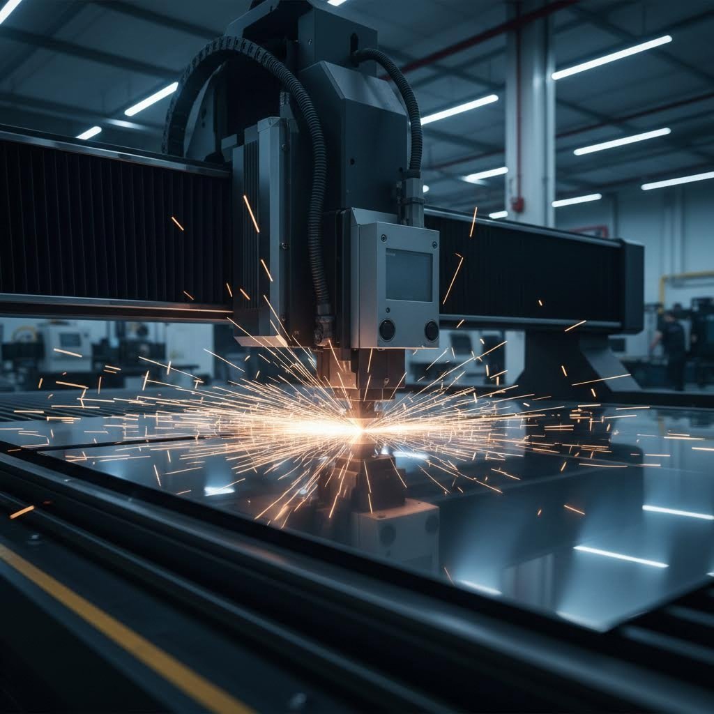
Pernah bertanya-tanya bagaimana produsen mengubah sketsa digital sederhana menjadi komponen logam yang sempurna? Jawabannya terletak pada teknologi yang secara mendasar telah mengubah cara kita bekerja dengan logam. Pemotongan logam CNC menjembatani kesenjangan antara imajinasi dan kenyataan, mengubah desain komputer menjadi bagian nyata dengan akurasi luar biasa.
CNC merupakan kependekan dari Computer Numerical Control—proses manufaktur di mana perangkat lunak komputer yang telah diprogram sebelumnya mengatur pergerakan alat pemotong untuk membentuk logam dengan presisi yang diukur dalam seperseribu inci.
Mengurai Akronim CNC
Memahami arti CNC dimulai dari tiga komponennya. "Komputer" mengacu pada otak digital yang mengendalikan operasi. "Numerik" menggambarkan instruksi terkode (G-code dan M-code) yang mengarahkan setiap gerakan. "Kontrol" mewakili kemampuan sistem untuk menjalankan perintah-perintah ini dengan konsistensi yang tak berubah.
Ketika Anda menggabungkan elemen-elemen ini dengan mesin pemotong logam, Anda mendapatkan sistem yang mengikuti jalur digital secara tepat tanpa penyimpangan. Berbeda dengan operator manusia yang mungkin mengalami kelelahan atau menyebabkan variasi kecil, pemotongan logam dengan CNC memberikan hasil yang identik baik untuk bagian pertama maupun bagian keseribu.
Dari Desain Digital ke Bagian Logam Fisik
Perjalanan dari konsep hingga bagian jadi mengikuti alur yang efisien. Pertama, insinyur membuat model 3D menggunakan perangkat lunak CAD (Desain Berbantuan Komputer). Cetakan digital ini kemudian diubah menjadi instruksi yang dapat dibaca mesin melalui program CAM (Manufaktur Berbantuan Komputer).
Setelah dimuat ke dalam sistem CNC, instruksi ini mengarahkan alat pemotong mengikuti koordinat presisi berdasarkan sistem Cartesian tiga dimensi. Mesin mengetahui secara tepat posisi yang harus ditempati, kecepatan pergerakan, dan kedalaman pemotongan. Alur kerja dari digital ke fisik ini memungkinkan iterasi cepat—perubahan desain dapat diuji melalui operasi CNC tambahan tanpa penyesuaian perkakas atau pembuatan cetakan.
Mengapa Kendali Komputer Merevolusi Pemotongan Logam
Perbedaan antara pemotongan manual dan yang dikendalikan oleh CNC menunjukkan alasan teknologi ini mengubah proses manufaktur. Permesinan manual sangat bergantung pada keterampilan, koordinasi, dan pengalaman operator. Bahkan perajin mesin yang terampil pun dapat memperkenalkan variasi kecil melalui gerakan yang dikendalikan secara manual.
Permesinan CNC dan teknologi CNC menghilangkan variabilitas ini. Menurut ahli Industri , mesin CNC menggabungkan fitur canggih seperti mekanisme umpan balik, sistem pemantauan alat potong, dan penukar alat otomatis yang meningkatkan ketepatan jauh melampaui kemampuan manual. Permesinan multi-sumbu memungkinkan pemotongan tiga dimensi kompleks yang hampir mustahil dilakukan secara manual.
Manfaatnya mencakup berbagai bidang—mulai dari penghobi yang membuat proyek khusus hingga fasilitas industri yang memproduksi komponen dirgantara. Bagi bengkel kecil, CNC logam menawarkan akses terjangkau melalui mesin desktop. Bagi produsen, ini berarti kualitas konsisten pada ribuan suku cadang. Baik Anda menjelajahi pemotongan CNC untuk proyek pribadi atau mengevaluasi solusi industri, keunggulan dasarnya tetap sama: ketepatan dan pengulangan yang tak tertandingi, yang tidak dapat dicapai oleh metode manual.
Membandingkan Metode Pemotongan Logam CNC Secara Berdampingan
Memilih alat pemotong logam yang salah dapat menghabiskan ribuan dolar karena bahan yang terbuang dan waktu yang hilang. Dengan empat teknologi pemotongan CNC utama yang tersedia, memilih metode yang tepat untuk aplikasi spesifik Anda menjadi kunci keberhasilan. Mari kita bahas setiap pendekatan agar Anda dapat membuat keputusan yang tepat.
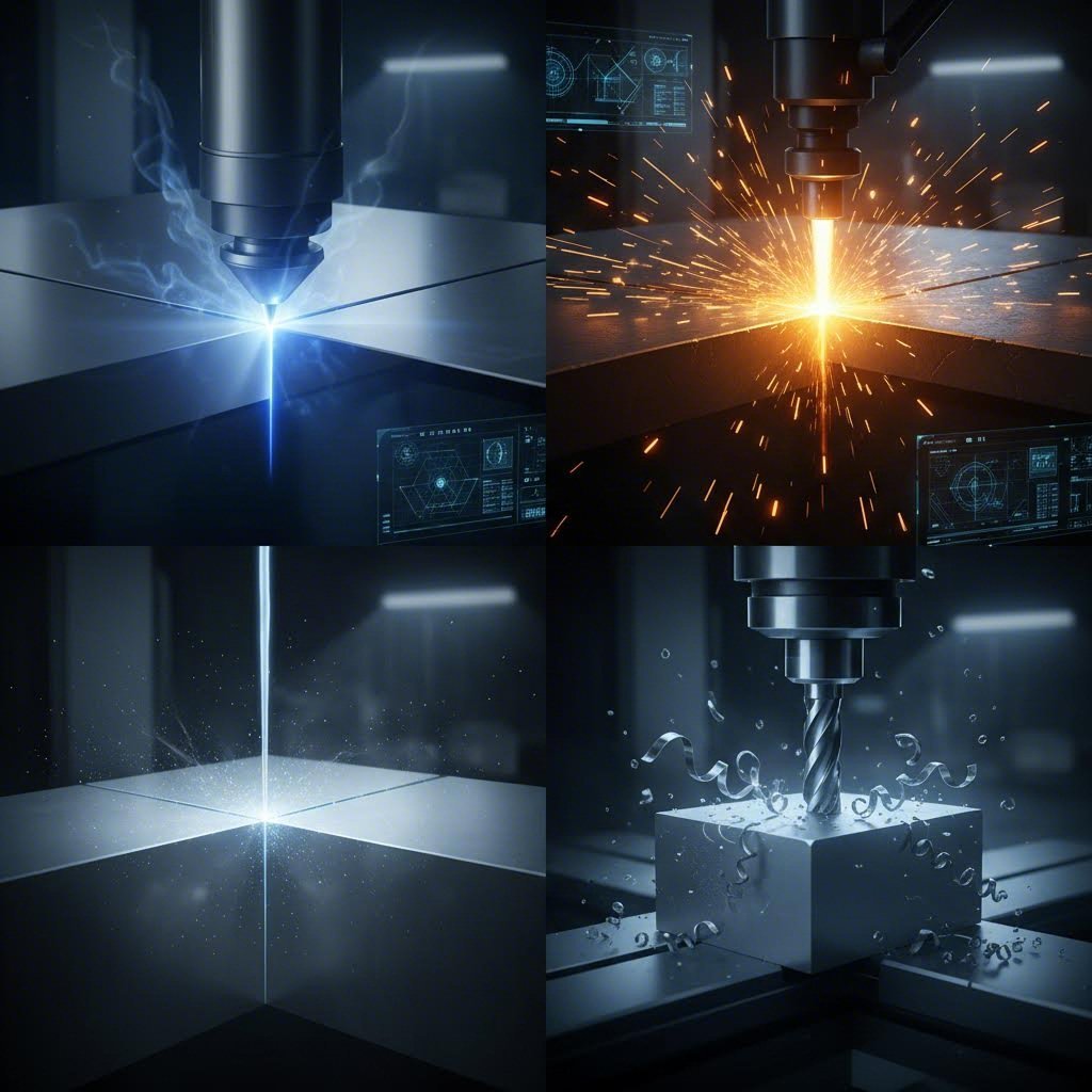
Ketepatan dan Keunggulan Kecepatan Pemotongan Laser
Bayangkan energi cahaya yang terfokus menjadi berkas setipis pisau, mampu memotong pola rumit dengan ketepatan bedah. Itulah yang dilakukan oleh pemotong laser. Teknologi ini sangat unggul saat bekerja dengan bahan pelat logam tipis , terutama ketika diperlukan detail halus atau lubang presisi.
Keunggulan utama dari pemotongan laser meliputi:
- Kualitas tepi yang luar biasa sehingga membutuhkan minimal perbaikan setelah proses pemotongan
- Kemampuan memotong lubang kecil dan bentuk rumit dengan sudut tajam
- Pemrosesan kecepatan tinggi pada material di bawah ketebalan 1/4 inci
- Kontrol lebar kerf yang presisi untuk komponen dengan toleransi ketat
- Kinerja sangat baik pada bahan pelat baja tahan karat dan pelat aluminium
Aplikasi terbaik mencakup perangkat elektronik, peralatan medis, dan produksi suku cadang presisi di mana tepi yang bersih paling penting.
Pemotongan Plasma untuk Aplikasi Pelat Tebal
Ketika Anda bekerja dengan logam konduktif tebal, pemotongan plasma mendominasi. Teknologi ini menggunakan busur listrik dan gas terkompresi untuk melelehkan serta menembus baja, aluminium, dan tembaga dengan kecepatan tinggi dan efisiensi biaya yang mengesankan.
Menurut Pengujian Wurth Machinery , pemotong plasma menunjukkan kinerja sangat baik pada pelat baja lebih dari 1 inci tebal—wilayah di mana pemotong laser kesulitan menembus. Keunggulannya menjadi jelas:
- Dapat menangani material dari 1/2 inci hingga beberapa inci tebal
- Kecepatan pemotongan tercepat untuk logam konduktif tebal
- Biaya operasional lebih rendah dibandingkan laser dan waterjet
- Sistem plasma lengkap berbiaya sekitar $90.000 dibandingkan $195.000 untuk sistem waterjet sebanding
Industri fabrikasi baja struktural, produksi peralatan berat, dan pembuatan kapal sangat bergantung pada pemotongan plasma karena alasan-alasan ini.
Teknologi Waterjet untuk Logam Sensitif Panas
Bagaimana jika Anda perlu memotong logam tanpa menimbulkan panas? Pemotongan waterjet menggunakan air bertekanan tinggi yang dicampur partikel abrasif untuk memotong hampir semua material—mulai dari baja hingga batu—tanpa efek termal. Pasar waterjet tumbuh pesat, diproyeksikan mencapai lebih dari $2,39 miliar pada tahun 2034.
Teknologi ini unggul ketika:
- Kerusakan akibat panas harus dihindari (tidak ada pelengkungan, pengerasan, atau zona terkena panas)
- Keberagaman material penting—dapat memotong logam, komposit, kaca, dan batu
- Material tebal hingga 12 inci membutuhkan pemotongan presisi
- Paduan sensitif memerlukan proses pemotongan dingin
Komponen aerospace dan aplikasi presisi di mana sifat metalurgi harus tetap tidak berubah mendapatkan manfaat paling besar dari teknologi waterjet.
Kemampuan CNC Milling dan Router
Tidak seperti metode lain yang memotong melalui material, sistem CNC milling dan CNC router menghilangkan material melalui alat pemotong berputar. Pendekatan ini menawarkan keunggulan unik—terutama kemampuan untuk membuat kontur 3D, kantong, dan geometri kompleks yang tidak mungkin dicapai dengan metode pemotongan 2D.
Namun, Anda akan melihat keterbatasan kecepatan saat menggunakan CNC router untuk logam dibandingkan dengan sistem pemotongan khusus. Diskusi di forum sering kali menyoroti kenyataan ini: router yang dirancang terutama untuk kayu dan plastik memerlukan penyesuaian parameter yang signifikan dan laju umpan yang lebih lambat saat memproses logam.
CNC Milling unggul dalam:
- Geometri 3D kompleks dan permukaan berkontur
- Pembuatan lubang presisi dan operasi penirusan
- Komponen yang membutuhkan beberapa operasi permesinan dalam satu pemasangan
- Toleransi ketat pada dimensi kritis
Perbandingan Metode Secara Lengkap Sekilas
Tabel perbandingan ini membantu Anda dengan cepat mengidentifikasi teknologi yang sesuai dengan kebutuhan spesifik Anda:
| Faktor | Pemotongan laser | Pemotongan plasma | Pemotongan Airjet | CNC Milling/Routing |
|---|---|---|---|---|
| Kisaran Ketebalan Material | 0.001" - 1" | 0,5" - 6"+ | 0,001" - 12" | Terbatas oleh jangkauan alat |
| Toleransi presisi | ±0,001" - 0,005" | ±0,015" - 0,030" | ±0,003" - 0,010" | ±0,0005" - 0,005" |
| Kualitas tepi | Sangat baik, finishing minimal | Baik, mungkin perlu digerinda | Sangat baik, tekstur sedikit | Sangat baik dengan perkakas yang tepat |
| Kecepatan Pemotongan | Sangat cepat (bahan tipis) | Cepat (bahan tebal) | Perlahan sampai sedang | Sedang |
| Biaya Operasional | Sedang sampai Tinggi | Rendah sampai Sedang | Tinggi (konsumsi abrasif) | Sedang (keausan perkakas) |
| Aplikasi Terbaik | Lembaran tipis, desain rumit, elektronik | Pelat tebal, baja struktural, fabrikasi berat | Bahan sensitif terhadap panas, dirgantara, bahan campuran | komponen 3D, bagian presisi, pekerjaan multi-operasi |
| Zona Terpengaruh Panas | Kecil | Sedang hingga besar | Tidak ada | Minimal dengan pendingin |
Menyesuaikan Ketebalan dengan Teknologi
Ketebalan material Anda sering menentukan metode pemotongan yang paling optimal:
- Lembaran logam tipis (di bawah 1/4") : Pemotongan laser memberikan kombinasi terbaik antara kecepatan, ketelitian, dan kualitas tepi
- Ketebalan sedang (1/4" hingga 1") : Semua metode dapat digunakan; pilih berdasarkan kebutuhan presisi dan sensitivitas terhadap panas
- Pelat tebal (lebih dari 1") : Plasma menawarkan kecepatan dan efisiensi biaya terbaik untuk logam konduktif; waterjet cocok untuk bahan non-konduktif atau yang sensitif terhadap panas
Banyak bengkel fabrikasi sukses pada akhirnya menggabungkan beberapa teknologi, dimulai dari sistem yang menangani proyek paling umum mereka. Saat kemampuan berkembang, penambahan metode pemotongan pendukung dapat menjangkau lebih banyak aplikasi dan membuka peluang baru.
Memahami perbedaan mendasar ini mempersiapkan Anda untuk memilih parameter pemotongan yang spesifik terhadap material pilihan Anda—yang memerlukan perhatian cermat terhadap sifat dan perilaku unik setiap jenis logam.
Parameter Pemotongan Khusus Material untuk Setiap Jenis Logam
Pernah memasukkan sepotong titanium yang indah ke mesin CNC Anda hanya untuk menghancurkan alat potong dalam hitungan detik? Parameter yang spesifik terhadap material membuat perbedaan antara komponen presisi dan bahan buangan yang mahal. Setiap logam membawa tantangan unik—mulai dari kecenderungan aluminium menempel pada alat hingga perilaku pengerasan akibat pemrosesan pada baja tahan karat. Mari kita bahas parameter yang benar-benar efektif untuk setiap material.
Parameter dan Tantangan Pemotongan Aluminium
Lembaran aluminium termasuk salah satu Material ramah CNC yang akan Anda temui. Kekuatan tariknya yang relatif rendah (biasanya 70-700 MPa tergantung paduan) memungkinkan kecepatan pemotongan agresif yang akan merusak alat pada logam yang lebih keras. Namun, jangan biarkan kemudahan ini menipu Anda hingga menjadi ceroboh.
Parameter yang direkomendasikan untuk pemotongan aluminium:
- Kecepatan pemotongan: 200-400 meter per menit—jauh lebih tinggi dibandingkan baja
- Laju Penyayatan: Laju pemakanan agresif berfungsi dengan baik; hitung menggunakan beban serpihan 0,05-0,15 mm per gigi
- Peralatan: Mata bor dua atau tiga alur memaksimalkan pelepasan serpihan
- Cairan Pendingin: Pendinginan banjir atau kabut mencegah terbentuknya tepi yang menumpuk
Kesalahan umum saat memotong aluminium meliputi:
- Pengelasan serpihan: Sifat lunak aluminium menyebabkannya menempel pada tepi pemotong, membentuk tepi yang menumpuk sehingga mengurangi kualitas permukaan
- Evakuasi serpihan yang tidak memadai: Menggunakan terlalu banyak alur memerangkap serpihan dalam potongan, menyebabkan pemotongan ulang dan peningkatan suhu
- Asumsi paduan yang salah: 6061-T6 diproses secara berbeda dibandingkan aluminium cor - verifikasi sifat spesifik dari paduan yang digunakan
Untuk aplikasi pengelasan aluminium di mana tepi potongan akan disambung, utamakan kualitas tepi daripada kecepatan. Kecepatan pemakanan lebih lambat dengan alat yang tajam dan dilapisi menghasilkan permukaan yang lebih bersih dan memberikan hasil pengelasan yang lebih andal.
Pertimbangan Pemesinan Baja dan Baja Tahan Karat
Baja menuntut rasa hormat. Kekuatan tariknya yang lebih tinggi memerlukan kecepatan yang dikurangi dan perhatian cermat terhadap manajemen panas. Saat bekerja dengan pelat baja tahan karat, tantangan bertambah akibat perilaku pengerasan selama proses pengerjaan.
Parameter baja karbon standar:
- Kecepatan pemotongan: 60-120 meter per menit untuk baja lunak
- Laju Penyayatan: Kecepatan pemakanan sedang mencegah timbulnya panas berlebih
- Peralatan: Milling karbida dengan lapisan TiAlN tahan terhadap keausan
- Cairan Pendingin: Penting untuk kendali panas dan memperpanjang umur alat
baja tahan karat 316 memerlukan perhatian khusus. Menurut ahli permesinan , kelas austenitik ini mengalami pengerasan cepat, artinya jeda atau tinggal diam saat pemotongan menciptakan lapisan permukaan yang mengeras dan secara drastis mempercepat keausan alat
Pedoman penting untuk baja tahan karat:
- Kecepatan pemotongan: 40-80 meter per menit - lebih rendah daripada baja karbon
- Laju Penyayatan: Pertahankan kontak yang konsisten; jangan biarkan alat menggesek tanpa pemotongan
- Kedalaman Potong: Lakukan pemotongan lebih dalam daripada beberapa pemotongan ringan untuk memotong di bawah lapisan yang mengeras akibat proses kerja
- Ketajaman alat: Ganti alat sebelum menjadi tumpul; tepi yang aus menghasilkan panas berlebih
Opsi pasca-pemrosesan untuk stainless meliputi brushing, elektropolishing, polishing mekanis, dan sandblasting - masing-masing memengaruhi ketahanan korosi dan penampilan estetika secara berbeda.
Bekerja dengan Titanium dan Paduan Eksotis
Pemesinan CNC Titanium merupakan puncak dari tantangan pemotongan. Bahan favorit industri dirgantara ini menggabungkan rasio kekuatan terhadap berat yang tinggi dengan kemampuan mesin yang sangat sulit. Konduktivitas termalnya yang rendah menyebabkan panas terkonsentrasi pada tepi potong, bukan menyebar melalui benda kerja.
Parameter pemesinan Titanium:
- Kecepatan pemotongan: 30-70 meter per menit - jauh lebih lambat daripada aluminium atau baja
- Laju Penyayatan: Jaga beban chip yang memadai untuk mencegah gesekan dan pengerasan akibat pengerjaan
- Peralatan: Peralatan karbida tajam dengan lapisan khusus; pertimbangkan end mill yang dirancang khusus untuk titanium
- Cairan Pendingin: Pengiriman pendingin bertekanan tinggi langsung ke zona pemotongan sangat penting
Kesalahan umum dalam permesinan titanium:
- Kecepatan berlebihan: Menghasilkan panas yang dengan cepat merusak lapisan alat
- Dwell (berhenti sejenak): Menciptakan titik-titik pengerasan akibat pengerjaan yang menghancurkan lintasan alat selanjutnya
- Kekakuan tidak memadai: Kecenderungan springback pada titanium memperbesar getaran mesin atau cekaman kerja
- Mengabaikan warna chip: Chip berwarna biru atau ungu menunjukkan panas berlebih - segera kurangi kecepatan
Inconel, Hastelloy, dan paduan super berbasis nikel lainnya memiliki tantangan serupa dengan persyaratan yang lebih ketat terhadap kualitas alat dan parameter pemotongan.
Strategi Logam Lunak Kuningan dan Tembaga
Logam lunak seperti kuningan dan tembaga menawarkan kemampuan mesin yang sangat baik tetapi memiliki kekhasan tersendiri. Saat membandingkan kuningan vs perunggu, kuningan biasanya lebih mudah dikerjakan karena kandungan sengnya, sedangkan kandungan timah pada perunggu meningkatkan kekerasannya.
Menurut penelitian pemesinan kuningan dari TFG USA, studi terbaru menunjukkan bahwa kuningan mampu menjalani proses pemesinan yang jauh lebih intensif dibandingkan yang sebelumnya dipercaya. Kelunakan dan stabilitas material ini membuatnya ideal untuk komponen presisi.
Parameter pemotongan kuningan:
- Kecepatan pemotongan: Kecepatan tinggi bekerja dengan baik; kuningan dapat menangani parameter agresif
- Laju Penyayatan: Mengatur laju pemakanan mengendalikan pembentukan chip - penting untuk mencegah chip berbentuk pita panjang yang merusak mesin
- Peralatan: Peralatan karbida dengan sudut rake positif meminimalkan pembentukan duri
- Cairan Pendingin: Seringkali opsional; banyak paduan kuningan dapat dipotong dengan baik secara kering
Pertimbangan permesinan tembaga:
- Perilaku lengket: Tembaga murni cenderung menempel pada peralatan lebih daripada kuningan
- Geometri peralatan: Tepi tajam dengan alur yang dipoles mengurangi adhesi material
- Penyesuaian laju pemakanan: Laju pemakanan yang lebih tinggi dapat membantu memutuskan serpihan daripada menciptakan untaian
- Hasil Permukaan: Mencapai hasil akhir yang sangat baik dengan kecepatan yang tepat dan peralatan yang tajam
Baik kuningan maupun tembaga mendapatkan manfaat dari sudut rake positif yang memotong material dengan bersih alih-alih mendorongnya. Pembentukan duri tetap menjadi tantangan umum—yang dapat diatasi melalui pemilihan kecepatan potong yang tepat serta peralatan potong yang tajam dan berkualitas tinggi.
Memahami parameter khusus material ini menjadi dasar, namun memilih alat potong dan pelapisan yang tepat akan meningkatkan hasil Anda secara signifikan.

Memilih Alat Potong dan Pelapisan yang Tepat
Anda telah mengatur parameter material Anda dengan sempurna—tetapi apakah Anda merusak hasil Anda dengan pemilihan alat yang salah? Alat potong yang Anda pilih menentukan segalanya, mulai dari kualitas permukaan hingga berapa banyak bagian yang dapat diproduksi sebelum mengganti end mill mahal tersebut. Mari kita uraikan keputusan pemilihan alat yang membedakan hasil amatir dengan hasil profesional dalam pemesinan logam CNC.
Jenis End Mill dan Kapan Menggunakan Masing-Masing
Tidak semua end mill diciptakan sama. Material yang digunakan pada alat Anda secara langsung memengaruhi kinerja, umur pakai alat, dan jenis logam yang dapat Anda kerjakan dengan sukses.
Baja Kecepatan Tinggi (HSS) memberikan ketahanan aus yang baik dengan biaya terendah. Menurut Panduan end mill MSC , HSS bekerja dengan baik untuk penggilingan serbaguna bahan ferrous maupun non-ferrous. Ini merupakan pilihan awal untuk proyek hobi dan aplikasi ringan.
Kobalt (M-42: Kobalt 8%) meningkatkan kinerja secara signifikan. Material ini menawarkan ketahanan aus, kekerasan pada suhu tinggi, dan ketangguhan yang lebih tinggi dibandingkan HSS standar. Anda dapat mengoperasikan alat kobalt sekitar 10% lebih cepat daripada setara HSS, menjadikannya ideal untuk pengerjaan besi cor, baja, dan paduan titanium ketika keterbatasan anggaran mencegah penggunaan karbida.
Solid Carbide mewakili standar profesional untuk pemesinan logam CNC milling. Alat-alat ini menawarkan kekakuan dan ketahanan panas yang unggul, beroperasi 2-3 kali lebih cepat dibanding HSS pada banyak aplikasi. Mata bor carbide persegi sangat baik untuk alur presisi dan profiling pada besi cor, logam non-ferrous, plastik, dan material keras. Namun, laju pemakanan berat lebih cocok menggunakan alat HSS atau kobalt karena sifat rapuh carbide terhadap beban kejut.
Logam Serbuk (PM) menjadi jembatan antara HSS dan carbide padat. Lebih tahan lama dan hemat biaya dibanding carbide padat dengan ketahanan tinggi terhadap patah, alat PM bekerja sangat baik pada material dengan kekerasan di bawah 30 RC dan pada aplikasi pengolahan kasar dengan kejut tinggi.
- Pekerjaan serba guna: HSS atau kobalt untuk bengkel dengan anggaran terbatas
- Pemesinan aluminium kecepatan tinggi: Carbide padat dengan alur mengilap
- Baja dan baja tahan karat: Carbide berlapis untuk umur alat optimal
- Pengerjaan kasar berat: Logam serbuk atau kobalt untuk ketahanan terhadap kejut
- Proses akhir pada aluminium anodized: Karbida tajam dengan pelapisan yang sesuai mencegah kerusakan lapisan
Teknologi Pelapisan Dijelaskan
Bayangkan pelapis alat seperti baju besi untuk tepian pemotong Anda. Pelapis yang tepat dapat memperpanjang masa pakai alat secara signifikan sekaligus memungkinkan kecepatan pemotongan yang lebih tinggi. Namun, memilih pelapis yang salah akan menyia-nyiakan uang atau membatasi kinerja.
Menurut penelitian kinerja pelapis , pemilihan pelapis yang tepat meningkatkan efisiensi produksi sebesar 20% hingga 70%, meningkatkan akurasi permesinan sebesar 0,5 hingga 1 tingkat, dan mengurangi biaya keausan alat sebesar 20% hingga 50%.
TiN (Titanium Nitride) - Pelapis klasik berwarna emas dengan kekerasan sekitar 2000-2500 HV. TiN bekerja dengan baik untuk permesinan umum pada kecepatan rendah hingga sedang tetapi lebih cepat aus saat pemotongan kecepatan tinggi. Ini adalah pilihan standar yang serbaguna dan hemat biaya untuk produksi campuran termasuk baja, aluminium, dan plastik.
TiAlN (Titanium Aluminum Nitride) - Opsi performa tinggi dengan kekerasan melebihi 3000 HV. Pada suhu tinggi, TiAlN membentuk lapisan oksida aluminium pelindung yang secara signifikan meningkatkan stabilitas termal. Lapisan ini tahan terhadap suhu di atas 800°C, menjadikannya ideal untuk pemotongan kecepatan tinggi dan permesinan kering pada baja dan paduan keras. TiAlN memberikan umur potong beberapa kali lebih panjang dibandingkan TiN saat memotong material sulit.
DLC (Diamond-Like Carbon) - Memiliki koefisien gesekan sangat rendah (sekitar 0,1-0,15), menjadikannya sangat cocok untuk logam non-besi. DLC sangat mengurangi hambatan pemotongan dan menghasilkan permukaan yang lebih halus. Namun, DLC terdegradasi di atas 350°C, sehingga tidak cocok untuk permesinan baja dalam waktu lama. Pilih DLC untuk pengerjaan aluminium dan tembaga berkecepatan tinggi di mana kualitas permukaan paling penting.
- Permesinan baja volume tinggi: Lapisan TiAlN untuk ketahanan panas dan umur panjang
- Aluminium dan tembaga: Lapisan DLC untuk gesekan rendah dan hasil akhir sangat baik
- Produksi campuran serba guna: Lapisan TiN untuk kinerja seimbang dan biaya ekonomis
- Bagian yang memerlukan finishing lapisan bubuk: Peralatan berlapis DLC mengurangi duri yang muncul menembus lapisan akhir
Pemilihan Jumlah Alur untuk Logam yang Berbeda
Berapa jumlah alur yang seharusnya dimiliki end mill Anda? Pertanyaan yang tampak sederhana ini sangat memengaruhi pembuangan serpihan, kualitas permukaan, dan kecepatan pemakanan. Kesalahan dalam memilih dapat menyebabkan potongan tersumbat atau produksi yang tidak perlu melambat.
Menurut Analisis komprehensif CNC Cookbook , aturan umumnya adalah menggunakan 4 alur untuk pemesinan baja dan paduan keras, sedangkan 2 alur paling cocok untuk aluminium dan material non-ferrous.
end Mill 2-Alur: Dirancang untuk material lunak seperti aluminium dan plastik. Lembah alur yang lebih besar memberikan pembuangan serpihan yang unggul serta laju penghilangan material yang lebih tinggi. End mill 2-alur karbida padat menawarkan kinerja sangat baik untuk operasi pembuatan alur di mana serpihan perlu keluar secara efisien. Peralatan ini juga bekerja dengan baik saat memotong delrin dan plastik teknik lainnya.
end Mill 3-Alur: Alternatif peningkatan kinerja dibanding desain 2-flute. Tambahan flute memungkinkan laju pemakanan yang lebih cepat untuk kecepatan permukaan tertentu, menjadikannya ideal untuk aplikasi pengasaran aluminium di mana Anda menginginkan laju penghilangan material maksimum.
milling Cutter 4-Flute: Dirancang untuk material keras seperti baja, stainless steel, dan besi. Jumlah flute yang lebih banyak berarti inti lebih besar dan kekuatan alat meningkat. Desain empat flute memberikan hasil akhir yang lebih halus serta mampu menangani pemotongan kecepatan tinggi pada material keras secara efisien. Ini adalah pilihan utama untuk pekerjaan pemotongan umum dan penyempurnaan pada logam ferrous.
Jumlah Flute Tinggi (5+ flute): Disediakan untuk material yang sangat keras seperti titanium, paduan nikel suhu tinggi, dan stainless steel. Karena material ini tidak dapat diputar cepat tanpa merusak mata potong, memiliki lebih banyak flute menjaga laju pemakanan tetap tinggi sehingga laju penghilangan material tetap dapat diterima meskipun kecepatan spindel lebih rendah.
Ini trik licik untuk penggilingan teks dan operasi periferal pada aluminium: Anda mungkin bisa menggunakan mata potong 4 alur ketika hanya sisi ujung mata bor yang menyentuh material. Karena serpihan tidak terperangkap dalam alur sempit, pembuangan tetap memadai sementara laju pemakanan meningkat.
Lebar Kerf dan Akurasi Dimensi
Setiap alat potong menghilangkan material - dan lebar penghilangan ini (kerf) secara langsung memengaruhi dimensi akhir bagian Anda. Memahami kompensasi kerf mencegah bagian yang terlalu kecil atau terlalu besar.
Diameter alat menentukan lebar kerf dalam operasi penggilingan. Sebuah end mill 1/4" menciptakan potongan sekitar lebar 1/4", tetapi lenturan alat di bawah gaya pemotongan dapat sedikit melebarkannya. Alat yang aus juga memotong lebih lebar karena tepinya semakin tumpul.
Program jalur alat Anda dengan mempertimbangkan:
- Offset jari-jari alat: Perangkat lunak CAM mengkompensasi secara otomatis jika dikonfigurasi dengan benar
- Toleransi keausan alat: Sertakan toleransi untuk pengurangan diameter secara bertahap
- Lenting balik material: Beberapa logam melentur saat pemotongan, memengaruhi dimensi akhir
Strategi Pendingin dan Pelumasan
Aplikasi pendingin yang tepat memperpanjang umur alat, meningkatkan hasil permukaan, dan memungkinkan parameter pemotongan yang lebih cepat. Operasi yang berbeda menuntut pendekatan yang berbeda pula.
- Pendingin banjir: Paling baik untuk permesinan baja dan baja tahan karat; aliran kontinu menghilangkan panas dan membersihkan serpihan
- Pendingin kabut: Cocok untuk aluminium; memberikan pelumasan tanpa kekhawatiran kejut termal
- Pelumasan kuantitas minimum (MQL): Opsi ramah lingkungan yang mengaplikasikan jumlah pelumas secara tepat langsung ke zona pemotongan
- Pemesinan Kering: Cocok untuk kuningan dan beberapa paduan aluminium; memerlukan alat berlapis TiAlN yang dirancang untuk suhu tinggi
- Cairan pendingin tekanan tinggi: Penting untuk titanium dan paduan eksotis; mengalirkan cairan pendingin langsung ke tepi pemotongan untuk ekstraksi panas maksimal
Dengan peralatan potong yang dipilih dan dilapisi sesuai bahan spesifik Anda, faktor kritis berikutnya adalah bagaimana Anda menahan benda kerja tersebut dengan kuat selama operasi pemotongan.
Solusi Penjepitan yang Menjamin Akurasi Pemotongan
Pernahkah Anda melihat proses pemotongan yang telah diprogram dengan sempurna gagal karena material bergeser di tengah operasi? Kegagalan penjepitan menyebabkan lebih banyak produk cacat daripada yang diakui sebagian besar operator mesin. Kenyataannya sederhana: sekalipun alat potong dan parameter sudah optimal, semuanya menjadi sia-sia jika pelat logam Anda bergerak selama pemotongan. Mari kita bahas strategi perlengkapan yang menjaga benda kerja tetap pada posisinya.
Strategi Pengikatan untuk Logam Lembaran
Pengikatan tepi konvensional menimbulkan masalah langsung pada material tipis. Menurut Penelitian permesinan DATRON , lembaran tipis secara inheren memiliki kekakuan yang lebih rendah, sehingga pencekaman tepi menjadi hampir mustahil tanpa lembaran terangkat atau bergeser selama proses permesinan. Gaya potong dari end mill cenderung menarik material ke atas, menyebabkan pergerakan dan ketidakakuratan.
Operator sering mengompensasi dengan menjalankan mesin pada kecepatan lebih lambat—mengorbankan produktivitas untuk mengatasi keterbatasan pencekaman. Ini bukanlah solusi terhadap masalah; ini hanya cara yang buruk untuk mengakalinya.
Strategi pencekaman yang efektif untuk berbagai ketebalan:
- Lembaran tipis (di bawah 3mm): Hindari pembebanan titik dengan penjepit konvensional; metode pencekaman tersebar bekerja lebih baik
- Ketebalan sedang (3-12mm): Penjepit toe dengan rahang lunak atau penjepit berjenjang yang diposisikan secara strategis
- Pelat baja tebal (12mm ke atas): Pencekaman mekanis standar dengan torsi yang cukup berfungsi secara andal
- Besi Lapis Galvanis: Gunakan pelat pelindung untuk mencegah kerusakan lapisan pada titik kontak penjepit
Tantangan lentur dan melengkung bertambah ketika pengikatan yang tidak tepat memperkenalkan tegangan ke dalam material tipis. Penelitian dari studi permesinan dinding tipis menunjukkan bahwa rahang keras konvensional memusatkan beban pada beberapa titik, menyebabkan distorsi lokal di bawah penjepit yang tetap sebagai kelengkungan atau puntiran permanen setelah dilepaskan.
Meja Vakum dan Perlengkapan Magnetik
Ketika Anda membutuhkan tekanan penahan seragam di seluruh pelat baja atau lembaran, perlengkapan vakum memberikan hasil luar biasa. Sistem ini—biasanya chuck aluminium dengan alur berkelok-kelok—menahan lembaran dengan cepat dan kuat saat terhubung ke tekanan vakum yang memadai.
Sebuah bengkel dirgantara memroses kulit aluminium setebal 1,2 mm pada chuck vakum, mencapai kerataan dalam kisaran 0,03 mm setelah proses roughing dan finishing—dibandingkan dengan 0,15 mm menggunakan penjepit tepi. Itu merupakan peningkatan akurasi lima kali lipat hanya dengan mengubah metode penjepitan.
Namun, meja vakum memiliki keterbatasan kritis: Anda tidak dapat memotong sepenuhnya melalui material di dalam area yang tersegel tanpa kehilangan tekanan vakum. Hal ini mengharuskan adanya operasi sekunder atau pendekatan alternatif untuk pemotongan tembus.
Solusi vakum canggih kini mengatasi keterbatasan ini. Sistem dengan lapisan korban permeabel memungkinkan pemotongan profil secara lengkap sambil tetap menjaga pegangan pada bagian-bagian kecil. Vakum menarik melalui material permeabel, mengamankan lembaran terlepas dari apakah potongan menembus sepenuhnya atau tidak.
Perlengkapan magnetik menawarkan solusi lain untuk pelat baja ferrous. Perlengkapan ini memberikan penjepitan instan tanpa waktu persiapan, namun hanya berfungsi dengan material magnetik—sehingga mengeliminasi aluminium, kuningan, dan baja tahan karat dari pertimbangan.
Prinsip Desain Jig Khusus
Terkadang solusi standar tidak sesuai dengan geometri spesifik Anda. Perlengkapan konformal yang mengikuti bentuk tepat dari bagian Anda mendistribusikan gaya penjepitan ke seluruh area kontak yang luas, sehingga menjaga beban titik tetap rendah.
Seorang produsen perangkat medis yang menggunakan perlengkapan konformal berisi epoksi untuk rumah implan titanium dengan dinding setebal 0,8 mm berhasil mengurangi distorsi dari 0,12 mm menjadi 0,02 mm—peningkatan akurasi dimensi sebesar 83%.
Ikuti proses pemasangan perlengkapan langkah demi langkah ini untuk hasil optimal:
- Analisis geometri bagian Anda - Identifikasi bagian-bagian tipis, fitur tinggi, dan area yang rentan melendut selama pemotongan
- Pilih metode penjepitan utama - Pilih sistem vakum, mekanis, atau magnetik berdasarkan material dan ketebalan
- Desain lokasi penopang - Tempatkan penopang tepat di bawah zona pemotongan untuk meminimalkan lendutan
- Verifikasi distribusi gaya penjepitan - Pastikan tidak ada satu titik pun yang menerima tekanan berlebihan yang menyebabkan deformasi lokal
- Uji dengan pemotongan percobaan - Jalankan bagian contoh dan ukur distorsi sebelum produksi
- Pantau selama produksi - Periksa secara berkala tingkat vakum, torsi penjepit, atau daya cengkeram magnetik
Perlengkapan jenis pin modular memungkinkan penyesuaian cepat untuk geometri yang bervariasi. Pin yang dapat disesuaikan dengan ujung bulat mendukung rib dan web pada beberapa titik, dengan gaya per pin dibatasi hingga 10-20N. Sebuah pemasok otomotif memproses baki baterai aluminium dengan cara ini, mempertahankan toleransi ±0,025 mm pada dinding setebal 1,5 mm setelah pembentukan kontur penuh.
Penopang sementara—web atau tab korban yang dibiarkan terpasang selama proses roughing—menambah kekakuan tepat di lokasi yang dibutuhkan. Lepaskan komponen tersebut selama operasi finishing. Pendekatan bertahap ini mencegah distorsi selama penghilangan material yang agresif sambil menjaga ketelitian dimensi akhir.
Dengan benda kerja Anda terpasang dengan benar, memahami toleransi presisi yang benar-benar dicapai oleh setiap metode pemotongan akan membantu menetapkan ekspektasi yang realistis untuk produk jadi Anda.
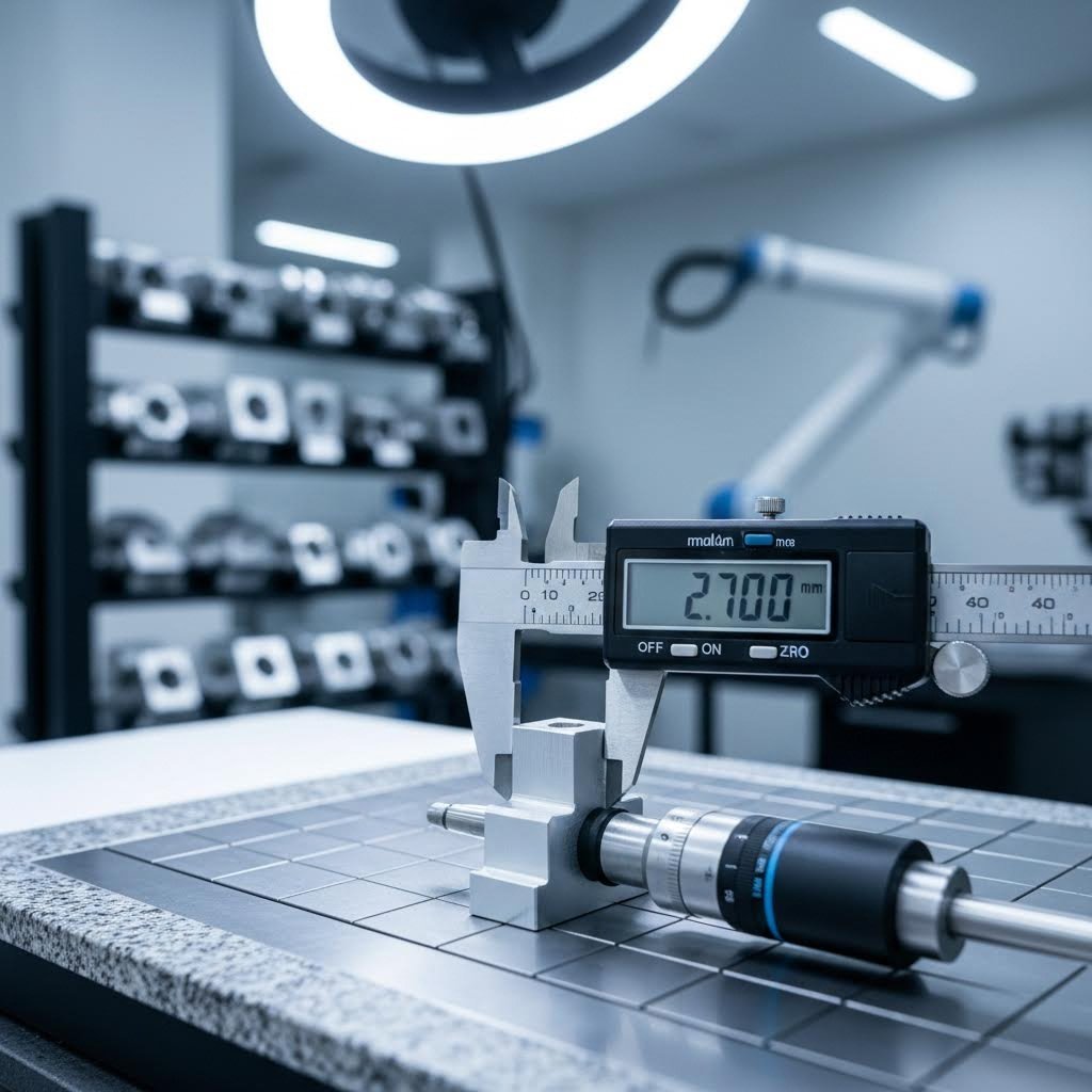
Memahami Kemampuan Presisi dan Toleransi
Toleransi apa yang benar-benar Anda butuhkan - dan apakah metode pemotongan yang Anda pilih dapat mencapainya? Pertanyaan ini menentukan apakah komponen Anda pas secara sempurna atau justru berakhir sebagai limbah mahal. Memahami toleransi yang dapat dicapai sebelum memilih metode pemotongan akan menghemat waktu, uang, dan menghindari frustrasi.
Toleransi mendefinisikan penyimpangan yang dapat diterima dari dimensi yang diinginkan pada suatu komponen yang diproduksi. Semakin ketat toleransinya, semakin presisi proses permesinan yang dibutuhkan - dan semakin tinggi biaya yang terkait.
Toleransi yang Dapat Dicapai Berdasarkan Metode Pemotongan
Setiap teknologi pemotongan CNC memberikan tingkat presisi yang berbeda berdasarkan prinsip operasi dasarnya. Menurut Penelitian toleransi Fabricast , pemilihan metode pemotongan secara langsung memengaruhi seberapa ketat toleransi yang dapat dicapai, tergantung pada keausan alat, kontrol mesin, jenis material, dan variabel proses.
| Metode Pemotongan | Jangkauan Toleransi Tipikal | Toleransi Terbaik | Catatan |
|---|---|---|---|
| Pemotongan laser | ±0,003" - 0,005" | ±0.001" | Zona yang terkena panas dapat memengaruhi material tipis |
| Pemotongan plasma | ±0,015" - 0,030" | ±0.010" | Lebih cocok untuk pelat tebal daripada pekerjaan presisi |
| Pemotongan Airjet | ±0,003" - 0,010" | ±0.001" | Tidak ada distorsi termal; sangat baik untuk logam yang peka terhadap panas |
| Cnc milling | ±0,001" - 0,005" | ±0.0005" | Presisi tertinggi yang tersedia; memerlukan penyiapan yang tepat |
| EDM/Wire EDM | ±0,0002" - 0,001" | ±0.0001" | Ultra-presisi untuk komponen skala mikro |
Saat meninjau tabel ketebalan pelat logam untuk menentukan ketebalan material, ingat bahwa ukuran gauge memengaruhi toleransi yang dapat dicapai. Sebagai contoh, baja gauge 14 (sekitar 0,075") bereaksi berbeda terhadap gaya pemotongan dibandingkan baja gauge 11 yang lebih tebal (sekitar 0,120"). Material yang lebih tipis lebih mudah melengkung, yang berpotensi memperlebar kisaran toleransi.
Faktor-Faktor yang Mempengaruhi Akurasi Dimensi
Bahkan dengan mesin CNC presisi tinggi, menjaga toleransi ketat tidak selalu mudah. Menurut analisis toleransi industri , penyimpangan kecil dapat menumpuk dan menyebabkan masalah besar dalam fungsi, kesesuaian, dan perakitan bagian.
Faktor-faktor kritis yang memengaruhi hasil Anda meliputi:
- Sifat bahan: Material yang lebih lunak atau lebih ulet dapat mengalami deformasi selama pemotongan, sehingga memengaruhi dimensi akhir
- Kekakuan mesin: Getaran atau backlash pada komponen mekanis menyebabkan variasi
- Pemakaian Alat: Degradasi bertahap ketajaman alat meningkatkan variasi dimensi sepanjang proses produksi
- Efek Termal: Panas dari pemotongan laser atau plasma menyebabkan pelengkungan atau ekspansi
- Keterampilan operator dan penyiapan: Kalibrasi dan pemasangan yang tepat tetap penting terlepas dari kualitas mesin
Suhu perlu mendapat perhatian khusus. Logam mengembang ketika dipanaskan—fenomena yang memengaruhi benda kerja selama pemotongan maupun pengukuran setelahnya. Sebuah bagian yang diukur segera setelah pemotongan laser mungkin memberikan hasil berbeda setelah didinginkan hingga suhu ruangan. Bengkel profesional mengendalikan suhu lingkungan dan membiarkan bagian-bagian tersebut stabil sebelum inspeksi akhir.
Sama seperti tabel ukuran mata bor yang membantu Anda memilih alat yang tepat untuk operasi pembuatan lubang, memahami kemampuan toleransi membantu Anda mencocokkan metode pemotongan dengan kebutuhan proyek.
Ketika ketepatan menjadi hal terpenting
Tidak semua aplikasi membutuhkan toleransi sangat ketat. Mencocokkan kebutuhan presisi dengan kebutuhan fungsional yang sebenarnya mencegah pengeluaran berlebihan untuk akurasi yang tidak diperlukan.
Aplikasi Dekoratif - Tanda logam khusus, karya seni, dan elemen arsitektural biasanya dapat menerima toleransi yang lebih longgar (±0,030" atau lebih longgar). Penampilan visual lebih penting daripada presisi dimensi, sehingga pemotongan plasma menjadi pilihan yang hemat biaya.
Fabrikasi umum - Komponen struktural, braket, dan panel enclosure biasanya memerlukan toleransi ±0,010" hingga ±0,015". Pemotongan laser atau waterjet secara efisien menangani aplikasi ini.
Perakitan presisi - Bagian-bagian yang harus pas satu sama lain atau berhubungan dengan komponen lain membutuhkan toleransi ±0,005" atau lebih ketat. Pemesinan CNC biasanya memberikan hasil yang andal.
Komponen kritis - Komponen aerospace, medis, dan otomotif sering kali memerlukan toleransi di bawah ±0,001". Aplikasi ini membenarkan penggunaan proses EDM atau pemesinan CNC presisi dengan langkah-langkah kontrol kualitas yang ketat.
Standar industri memberikan panduan untuk sektor-sektor tertentu. ISO 2768 menetapkan kisaran toleransi standar berdasarkan ukuran bagian dan tingkat presisi yang dibutuhkan. ASME Y14.5 mengatur toleransi geometrik untuk perakitan kompleks. Komponen aerospace (AS9100) dan medis (ISO 13485) mengikuti protokol ketat di mana akurasi dimensi secara langsung memengaruhi keselamatan.
Memahami toleransi yang benar-benar Anda butuhkan—dan metode pemotongan mana yang secara andal dapat mencapainya—akan menetapkan ekspektasi yang realistis serta membimbing keputusan manufaktur yang lebih cerdas. Dengan dasar-dasar presisi ini dipahami, Anda siap mencocokkan kebutuhan proyek spesifik Anda dengan pendekatan pemotongan CNC yang optimal.
Memilih Pendekatan Pemotongan CNC yang Tepat untuk Proyek Anda
Anda memahami metode pemotongan, parameter material, dan kemampuan toleransi - tetapi bagaimana sebenarnya Anda memutuskan pendekatan yang sesuai dengan situasi khusus Anda? Di sinilah banyak proyek terhambat. Mesin cnc terbaik untuk pekerjaan logam belum tentu merupakan pilihan yang paling mahal atau paling mumpuni; melainkan yang sesuai dengan kebutuhan unik Anda dalam hal presisi, volume, dan anggaran.
Bayangkan keputusan ini seperti memilih alat transportasi. Mobil sport, truk pickup, dan van pengiriman semuanya membawa Anda dari titik A ke B - tetapi memilih kendaraan yang salah untuk tugas tertentu akan menimbulkan masalah. Logika yang sama berlaku saat memilih mesin cnc untuk proyek logam.
Menyesuaikan Proyek Anda dengan Metode yang Tepat
Mulailah dengan mengajukan pertanyaan yang tepat mengenai aplikasi spesifik Anda. Menurut penelitian fabrikasi Zintilon, memilih metode pemotongan yang sesuai menentukan kualitas produk akhir, efisiensi produksi, efektivitas biaya, dan pemanfaatan material.
Gunakan daftar kriteria keputusan ini untuk mempersempit pilihan Anda:
- Jenis dan ketebalan material: Logam apa yang akan Anda potong, dan seberapa tebalnya? Lembaran aluminium tipis mengarah pada pemotongan laser, sedangkan pelat baja setebal 1 inci lebih cocok dengan plasma.
- Persyaratan ketelitian: Apakah Anda membutuhkan toleransi ±0,001" untuk komponen aerospace, atau toleransi ±0,030" sudah cukup untuk braket struktural?
- Sensitivitas terhadap panas: Apakah metode pemotongan termal akan merusak sifat material Anda? Paduan yang telah melalui perlakuan panas dan beberapa jenis baja tahan karat mungkin memerlukan proses pemotongan dingin dengan waterjet.
- Kebutuhan kualitas tepi: Apakah tepi hasil potongan harus siap las langsung, atau Anda bisa menganggarkan operasi finishing tambahan?
- Kompleksitas Desain: Profil sederhana dipotong secara efisien dengan plasma, sedangkan pola rumit dan fitur kecil membutuhkan ketepatan laser.
- Operasi hulu: Pertimbangkan bagaimana tepi potongan memengaruhi proses selanjutnya seperti pembengkokan, pengelasan, atau finishing.
Mesin pemotong logam CNC unggul ketika Anda membutuhkan pengulangan yang konsisten pada suku cadang yang identik. Namun jika Anda memotong prototipe satu kali pakai dengan perubahan desain yang sering, fleksibilitas metode yang dipilih lebih penting daripada kecepatan pemotongan semata.
Pertimbangan Anggaran dan Faktor Biaya
Biaya sebenarnya dari pemotongan CNC jauh melampaui investasi peralatan awal. Menurut Analisis Wurth Machinery , memilih teknologi yang salah dapat menelan biaya ribuan dolar karena bahan yang terbuang dan waktu yang hilang.
Faktorkan pertimbangan ekonomi ini ke dalam keputusan Anda:
- Investasi Modal Awal: Sistem plasma lengkap berharga sekitar $90.000, sedangkan sistem waterjet yang sebanding harganya sekitar $195.000. Sistem laser berada di antara keduanya tergantung pada daya dan fitur.
- Biaya operasional per kaki: Pemotongan baja tebal dengan plasma biayanya sekitar separuh dari pemotongan material yang sama dengan waterjet per kaki.
- Biaya perlengkapan habis pakai: Waterjet terus-menerus mengonsumsi media abrasif; plasma menggunakan elektroda dan nozzle; laser memerlukan perawatan gas dan optik.
- Pemborosan material: Lebar kerf bervariasi tergantung metode - kerf sempit dari laser memaksimalkan hasil material dibanding potongan lebih lebar dari plasma.
- Biaya operasi sekunder: Tepi kasar dari pemotongan plasma mungkin perlu digerinda sebelum pengelasan, menambah tenaga kerja dan waktu.
- Konsumsi energi: Pemotongan laser umumnya beroperasi lebih hemat energi dibanding proses plasma atau oksi-bahan bakar.
Jangan hanya fokus pada biaya per potong. Pertimbangkan waktu persiapan, potensi limbah material akibat kesalahan, serta biaya operasi sekunder seperti penghilangan duri atau pembersihan. Sistem pemotong logam yang menghasilkan tepi bersih dengan kecepatan sedang sering kali lebih unggul dibanding alternatif lebih cepat yang membutuhkan proses pasca yang luas.
Volume Produksi dan Kebutuhan Waktu Penyelesaian
Jumlah produksi Anda sangat memengaruhi mesin CNC untuk logam mana yang secara ekonomis masuk akal. Menurut penelitian manufaktur Prototech Laser, skala produksi secara langsung memengaruhi kelayakan ekonomi berbagai metode pemotongan.
Produksi prototipe dan volume rendah (1-50 suku cadang):
- Fleksibilitas lebih penting daripada kecepatan mentah
- Waktu persiapan mewakili persentase yang lebih besar dari total biaya proyek
- Waterjet dan plasma manual menawarkan fleksibilitas tanpa pemrograman yang rumit
- Pemesinan CNC menghilangkan perlunya perkakas mahal - mesin yang sama dapat menghasilkan bagian yang benar-benar berbeda dengan mengubah program digitalnya
Produksi volume menengah (50-500 bagian):
- Keseimbangan antara investasi persiapan dan efisiensi per bagian
- Pemotongan laser otomatis memaksimalkan kapasitas produksi sambil mempertahankan ketepatan
- Pertimbangkan perlengkapan khusus untuk mengurangi waktu persiapan antar batch
Produksi volume tinggi (500+ bagian):
- Optimalisasi biaya per unit menjadi sangat penting
- Sistem otomatis dengan penanganan material cepat membenarkan investasi modal yang lebih tinggi
- Pemotongan kecepatan tinggi atau pemotongan laser dengan pemuatan lembaran otomatis memaksimalkan produktivitas
- Waktu persiapan menjadi sangat kecil jika dirata-ratakan dalam ribuan komponen
Ketika Fungsi Ganda Masuk Akal
Haruskah Anda berinvestasi pada satu sistem mesin CNC logam serbaguna atau beberapa solusi khusus? Pertanyaan ini perlu dianalisis secara cermat berdasarkan campuran proyek Anda secara umum.
Pertimbangkan mesin fungsi ganda ketika:
- Proyek Anda mencakup berbagai jenis dan ketebalan material
- Ruang lantai bengkel membatasi jejak peralatan
- Anggaran modal membatasi pembelian beberapa peralatan
- Variasi pekerjaan mencegah pemanfaatan yang konsisten dari peralatan khusus
Solusi pemotongan khusus lebih masuk akal ketika:
- Anda mengkhususkan diri pada jenis material atau rentang ketebalan tertentu
- Volume produksi membenarkan penggunaan peralatan yang berjalan hampir pada kapasitas maksimal
- Persyaratan presisi melebihi kemampuan mesin kombinasi
- Waktu henti untuk pemeliharaan pada satu fungsi seharusnya tidak menghentikan seluruh produksi
Banyak bengkel fabrikasi sukses yang memulai dengan satu teknologi untuk menangani proyek-proyek paling umum mereka. Seiring pertumbuhan bisnis, penambahan metode pemotongan pendukung akan memperluas kemampuan dan basis pelanggan. Plasma dan laser sering kali saling melengkapi—plasma digunakan untuk pekerjaan struktural tebal, sedangkan laser memberikan presisi pada pelat tipis. Waterjet menambah fleksibilitas untuk material sensitif panas dan non-logam yang tidak dapat ditangani oleh plasma maupun laser.
Pilihan yang tepat pada akhirnya menyesuaikan teknologi dengan kebutuhan spesifik Anda—jenis material, rentang ketebalan, kebutuhan presisi, dan keterbatasan anggaran. Setelah memilih pendekatan pemotongan CNC yang tepat, pertimbangan berikutnya adalah skala peralatan yang sesuai dengan lingkungan produksi dan arah pertumbuhan Anda.
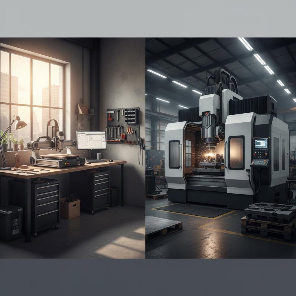
Pilihan Peralatan dari Skala Hobi hingga Industri
Anda telah memilih metode pemotongan dan memahami parameter-parameter tersebut—tetapi peralatan apa sebenarnya yang memberikan hasil sesuai skala Anda? Jarak antara mesin CNC desktop untuk logam dan sistem produksi industri tidak hanya mencakup perbedaan harga, tetapi juga kemampuan, kebutuhan ruang, dan ekspektasi yang realistis. Mari kita bahas apa sebenarnya yang ditawarkan oleh setiap tingkatan peralatan.
Pilihan CNC Desktop untuk Bengkel Kecil
Apakah mesin CNC rumahan untuk logam benar-benar dapat menghasilkan komponen berkualitas? Jawaban jujurnya: tergantung pada ekspektasi dan pilihan material Anda. Menurut Penelitian pemotongan logam CanCam , router CNC memang dapat memotong logam—namun tidak semua router cocok untuk tugas ini.
Sebuah router CNC logam yang dirancang untuk pekerjaan kayu memerlukan penyesuaian signifikan saat memproses logam. Mesin-mesin ini biasanya memiliki rangka yang lebih ringan, spindel yang lebih kecil, dan sistem pendingin yang dioptimalkan untuk debu daripada serpihan logam. Namun, sistem desktop khusus kini secara efektif menutup kesenjangan ini.
Apa yang ditawarkan oleh sistem mesin CNC logam desktop:
- Pemesinan aluminium dan kuningan: Logam lunak dapat dikerjakan dengan baik pada unit desktop berkualitas dengan laju umpan dan kecepatan yang tepat
- Pekerjaan baja ringan: Baja berketebalan tipis dapat dikerjakan dengan peralatan karbida dan parameter yang hati-hati
- Pengembangan Prototipe: Sangat baik untuk pengujian desain sebelum dilakukan produksi massal
- Produksi dalam jumlah kecil: Efisien secara biaya untuk jumlah kurang dari 50 buah
Keterbatasan realistis meliputi:
- Kendala kekakuan: Rangka yang lebih ringan melengkung di bawah gaya pemotongan, membatasi kedalaman potong dan ketepatan
- Daya Spindel: Motor biasanya berkapasitas 1-3 HP membatasi laju penghilangan material
- Ruang kerja: Meja yang lebih kecil membatasi ukuran maksimum benda kerja
- Kompromi kecepatan: Diskusi forum sering menyoroti bahwa router CNC untuk aplikasi logam berjalan jauh lebih lambat dibanding mesin milling khusus
Menurut Panduan peralatan CNC Cookbook , router CNC berkualitas tinggi dapat diperoleh dengan harga kurang dari $2.000—menjadikan pekerjaan logam dengan CNC tingkat pemula terjangkau bagi hobiis dan bengkel kecil. Namun, bersiaplah untuk menghabiskan dana $5.000–$15.000 untuk mesin yang dirancang khusus agar dapat menangani logam secara andal.
Sistem Pemotongan Kelas Industri
Ketika produksi menuntut keluaran yang konsisten pada ribuan komponen, sistem mesin cnc logam lembaran industri membenarkan investasi yang lebih tinggi. Mesin-mesin ini memiliki konstruksi yang kokoh, spindel bertenaga, serta kemampuan otomasi yang tidak dapat dicapai oleh unit desktop.
Pusat permesinan CNC industri menawarkan spindel dengan daya mulai dari 10-50+ HP dan rangka mesin yang kaku dengan berat mencapai ribuan pon. Massa besar ini menyerap getaran dan menjaga ketepatan selama kondisi pemotongan yang agresif. Konfigurasi multi-sumbu memungkinkan geometri kompleks yang mustahil dihasilkan pada mesin yang lebih sederhana.
Sistem pemotong plasma dan laser juga memiliki skala yang serupa. Mesin pemotong plasma CNC pemula mulai dari sekitar $5.000 menurut sumber industri, sedangkan sistem kelas produksi dengan penanganan material otomatis mencapai $50.000-$150.000. Peralatan pemotong laser memiliki rentang bahkan lebih luas—mulai dari $5.000 untuk sistem CO2 dasar hingga lebih dari $300.000 untuk laser serat berdaya tinggi dengan pemuatan otomatis.
Keunggulan industri meliputi:
- Operasi Kontinu: Dibuat untuk produksi multi-shift tanpa masalah overheat atau keausan
- Perawatan presisi: Konstruksi kaku mempertahankan toleransi selama proses produksi
- Integrasi Otomasi: Pemuatan robotik, pengganti palet, dan pengganti alat otomatis meminimalkan intervensi operator
- Penanganan Material: Meja yang lebih besar dapat menampung ukuran lembaran penuh dan pelat berat
Perbandingan Peralatan Berdasarkan Kemampuan
Perbandingan ini membantu Anda mengidentifikasi tingkatan peralatan yang sesuai dengan kebutuhan Anda:
| Faktor | Desktop/Hobi | Bengkel Kecil/Profesional | Produksi industri |
|---|---|---|---|
| Rentang Investasi | $2.000 - $15.000 | $15.000 - $75.000 | $75.000 - $500.000+ |
| Bahan Umum | Aluminium, kuningan, baja tipis | Baja, stainless, aluminium | Semua logam termasuk titanium |
| Lingkup Pekerjaan | 12" x 12" hingga 24" x 36" | 24" x 48" hingga 48" x 96" | Kapasitas lembaran penuh dan lebih besar |
| Volume produksi | Prototipe, 1-50 bagian | Batch kecil, 50-500 bagian | Volume tinggi, 500+ suku cadang |
| Ruang yang diperlukan | Sudut garasi, ruangan kecil | Ruang toko khusus | Fasilitas industri |
| Persyaratan Daya | Stopkontak standar 110V/220V | sirkuit khusus 220V | daya industri 3-fase |
| Tingkat Keterampilan yang Dibutuhkan | Pemula hingga Menengah | Menengah hingga lanjutan | Operator profesional |
| Aplikasi Tipikal | Proyek hobi, suku cadang kustom | Pekerjaan bengkel, produksi kecil | Manufaktur OEM, volume tinggi |
Meningkatkan Kemampuan Pemotongan Logam Anda
Pertumbuhan jarang terjadi dalam semalam—begitu pula investasi peralatan seharusnya tidak dilakukan terburu-buru. Pertumbuhan yang cerdas menyesuaikan peningkatan kapabilitas dengan permintaan aktual, bukan kebutuhan yang diperkirakan.
Pertimbangkan jalur perkembangan berikut:
- Mulai dengan fleksibilitas: Mesin cnc logam berkualitas yang mampu menangani berbagai material lebih baik daripada peralatan khusus yang menganggur
- Identifikasi hambatan: Lacak di mana peralatan saat ini membatasi kapasitas produksi atau kemampuan sebelum melakukan investasi
- Tambahkan teknologi pendukung: Jika router logam cnc Anda bekerja baik pada aluminium tetapi kesulitan pada baja, menambahkan pemotongan plasma akan memperluas kemampuan tanpa harus mengganti aset yang sudah ada
- Berinvestasi secara bertahap dalam otomatisasi: Pengganti alat otomatis, sistem probing, dan penanganan material meningkatkan produktivitas pada mesin yang sudah ada sebelum memerlukan peralatan modal baru
Perencanaan ruang sama pentingnya dengan anggaran. Mesin CNC logam tidak hanya membutuhkan ruang dasar mesin, tetapi juga ruang bebas untuk pemuatan material, pengelolaan serpihan, dan akses operator. Peralatan industri kerap membutuhkan sistem ventilasi khusus, sistem udara bertekanan, dan infrastruktur pengelolaan cairan pendingin.
Kebutuhan daya meningkat seiring kemampuan mesin. Sistem desktop berjalan pada sirkuit rumah tangga standar, namun pusat frais CNC industri membutuhkan daya tiga fasa yang mungkin memerlukan peningkatan layanan listrik senilai ribuan dolar sebelum mesin tiba.
Pengembangan keterampilan sejalan dengan investasi peralatan. Mesin senilai $100.000 yang dioperasikan oleh tenaga tak terlatih akan menghasilkan limbah mahal. Banyak produsen menawarkan program pelatihan, dan perguruan tinggi negeri setempat menyediakan kursus pemrograman CNC yang membangun kompetensi operator sebelum kemampuan peralatan terlampaui.
Baik Anda sedang melengkapi bengkel garasi maupun memperluas fasilitas industri, menyesuaikan peralatan dengan kebutuhan produksi yang realistis dapat mencegah investasi yang terlalu rendah sehingga membatasi kapabilitas maupun investasi berlebihan yang memberatkan anggaran. Dengan peralatan yang tepat dipilih dan dioperasikan, Anda siap membawa proyek pemotongan logam dari konsep hingga penyelesaian.
Meningkatkan Proyek Pemotongan Logam Anda ke Tingkat Berikutnya
Anda telah memahami dasar-dasar pemotongan logam dengan CNC—mulai dari parameter material dan pemilihan peralatan, hingga pilihan permesinan dan kemampuan toleransi. Kini tiba bagian yang menarik: menerapkan pengetahuan ini ke dalam aksi. Baik Anda sedang meluncurkan proyek pertama atau mengembangkan operasi yang sudah ada, langkah selanjutnya membutuhkan keputusan strategis tentang batas kemampuan Anda dan kapan saatnya memulai kemitraan profesional.
Memulai Proyek Pemotongan Logam Pertama Anda
Siap untuk membuat serpihan? Sebelum memasukkan material ke mesin Anda, ikuti pendekatan sistematis ini untuk memaksimalkan peluang keberhasilan pada bagian pertama. Menurut sumber daya pemula dari CNC Cookbook, memahami alur kerja lengkap dari desain hingga bagian jadi dapat mencegah kesalahan mahal yang sering membuat frustrasi bagi pemula.
- Tentukan kebutuhan proyek Anda secara jelas - Dokumentasikan jenis material, ketebalan, toleransi yang dibutuhkan, dan jumlah yang diperlukan sebelum menyentuh peralatan apa pun
- Buat atau dapatkan model CAD yang sesuai - Pastikan desain digital Anda memperhitungkan kenyataan manufaktur seperti jari-jari tekuk, lebar kerf, dan akses alat
- Pilih metode pemotongan berdasarkan kebutuhan proyek - Sesuaikan ketebalan material dan persyaratan presisi dengan teknologi yang tepat sebagaimana dibahas sebelumnya
- Hitung laju pemakanan dan kecepatan putaran untuk material spesifik Anda - Gunakan rekomendasi pabrikan sebagai titik awal, kemudian sesuaikan berdasarkan kondisi pemotongan aktual
- Siapkan sistem pencekaman yang tepat - Kunci material Anda dengan kuat untuk mencegah pergerakan selama operasi pemotongan
- Jalankan simulasi atau pemotongan tanpa material terlebih dahulu - Verifikasi jalur alat sebelum melakukan penghilangan material yang sesungguhnya
- Mulailah dengan uji potong pada material sisa - Atur parameter pada material murah sebelum memotong benda kerja asli Anda
- Periksa dan ukur hasilnya - Bandingkan dimensi akhir dengan spesifikasi sebelum melanjutkan ke produksi dalam jumlah besar
Bagi mereka yang membuat tanda logam khusus atau karya dekoratif, persyaratan toleransi menjadi jauh lebih longgar. Proyek-proyek ini merupakan titik awal yang sangat baik untuk mengembangkan keterampilan CNC tanpa tekanan spesifikasi ketat. Aplikasi yang lebih menuntut seperti braket presisi atau perakitan memerlukan pendekatan sistematis seperti yang diuraikan di atas.
Kapan Harus Bermitra dengan Tukang Fabrikasi Profesional
Inilah kenyataan yang sering ditolak banyak penggemar DIY: beberapa proyek benar-benar melampaui kemampuan peralatan rumahan atau bengkel kecil. Mengenali kapan harus bermitra dengan sumber daya fabrikasi logam profesional bukanlah pengakuan kekalahan—melainkan pengambilan keputusan manufaktur yang cerdas.
Menurut Analisis Wiley Metal , pekerjaan fabrikasi logam luar sumber menawarkan keuntungan signifikan yang melampaui sekadar kesesuaian kemampuan. Pelaku profesional berinvestasi pada mesin canggih untuk memotong, membengkokkan, dan mengelas—peralatan yang harganya mencapai angka enam atau bahkan tujuh digit yang didepresiasi melalui pesanan dari basis pelanggan besar.
Pertimbangkan kemitraan fabrikasi logam lembaran profesional ketika:
- Toleransi melebihi kemampuan peralatan Anda - Persyaratan presisi di bawah ±0,005" sering kali membutuhkan mesin kelas industri
- Ketebalan material melebihi kapasitas mesin Anda - Pelat baja tebal memerlukan sistem plasma atau waterjet yang melampaui peralatan bengkel biasa
- Volume melebihi produksi internal yang praktis - Produksi dalam jumlah ratusan atau ribuan unit membenarkan efisiensi profesional
- Standar kualitas bersertifikat berlaku - Aplikasi dirgantara, otomotif, dan medis memerlukan sistem kualitas yang terdokumentasi
- Bahan eksotis menimbulkan tantangan - Titanium, Inconel, dan paduan khusus membutuhkan pengalaman dan peralatan yang kebanyakan bengkel tidak miliki
Mencari "bengkel fabrikasi terdekat" atau "jasa fabrikasi logam terdekat" menghubungkan Anda dengan sumber daya lokal. Namun, kedekatan geografis kurang penting dibanding kesesuaian kemampuan. Sebuah bengkel spesialis fabrikasi baja di seberang negeri mungkin lebih cocok untuk proyek pelat baja Anda daripada bengkel umum di sekitar sudut.
Pengalaman sangat penting saat memilih mitra fabrikasi. Menurut para ahli industri, seorang tukang fabrikasi berpengalaman sering kali dapat melihat gambar teknik bagian dan memberikan saran untuk memperbaiki tampilan, mengurangi biaya, atau meningkatkan kualitas—pengalaman yang dibangun dari mengerjakan sejumlah besar pekerjaan berbeda untuk berbagai pelanggan menggunakan berbagai jenis material.
Untuk aplikasi otomotif yang memerlukan standar kualitas bersertifikat, bermitra dengan produsen yang bersertifikasi IATF 16949 memastikan komponen sasis, suspensi, dan struktural Anda memenuhi persyaratan industri. Produsen seperti Shaoyi (Ningbo) Teknologi Logam menawarkan dukungan DFM komprehensif dan kemampuan prototipe cepat—memberikan penawaran dalam waktu 12 jam dan prototipe dalam waktu sesingkat 5 hari. Ini mempercepat siklus pengembangan untuk proyek pemotongan logam kompleks di mana iterasi desain dan kualitas bersertifikat sama-sama penting.
Mengoptimalkan Alur Kerja Produksi Anda
Baik Anda menangani proyek secara internal maupun berkoordinasi dengan mitra eksternal, optimalisasi alur kerja memaksimalkan hasil sekaligus meminimalkan pemborosan dan frustrasi.
Menurut penelitian prototipe Fictiv, menerapkan prinsip Desain untuk Kemudahan Produksi (DFM) sejak dini memastikan prototipe dan produksi akhir berjalan lancar. Gunakan radius tekuk yang konsisten, minimalkan toleransi ketat di mana tidak diperlukan secara fungsional, dan hindari geometri yang terlalu kompleks yang meningkatkan biaya tanpa menambah nilai.
Untuk mesin CNC dalam operasi fabrikasi logam, pertimbangkan peningkatan alur kerja berikut:
- Standardisasi pengadaan material - Gunakan ukuran lembaran umum dan ketebalan standar untuk mengurangi kompleksitas persediaan
- Susun bagian secara efisien - Maksimalkan pemanfaatan material dengan mengoptimalkan penataan bagian pada lembaran bahan
- Dokumentasikan parameter yang berhasil - Buat lembar persiapan khusus material untuk hasil yang dapat diulang pada pekerjaan mendatang
- Bangun jalur dari prototipe ke produksi - Tetapkan proses yang dapat ditingkatkan skalanya dari satu prototipe menjadi produksi volume tanpa harus memulai dari awal
- Terapkan titik pemeriksaan kualitas - Deteksi masalah lebih awal daripada menemukan masalah setelah menyelesaikan seluruh batch
Transisi dari prototipe ke produksi layak mendapat perhatian khusus. Menurut penelitian prototipe logam lembaran, ketika jumlah prototipe yang dibuat cukup banyak, batas antara pembuatan prototipe dan produksi skala kecil mulai kabur. Prototipe logam lembaran menghilangkan kebutuhan akan perkakas kompleks dan mahal, menjadikannya pilihan yang praktis dan terjangkau untuk produksi volume rendah setelah persetujuan desain akhir.
Keberhasilan fabrikasi logam pada akhirnya bergantung pada kesesuaian kemampuan dengan kebutuhan—mengetahui kapan peralatan dan keterampilan Anda mampu menangani proyek secara percaya diri, serta menyadari kapan kemitraan profesional memberikan hasil yang lebih baik. Pengetahuan yang telah Anda peroleh mengenai metode pemotongan, parameter material, pemilihan perkakas, dan kemampuan presisi menempatkan Anda dalam posisi yang lebih cerdas untuk membuat keputusan tersebut.
Langkah selanjutnya? Pilih proyek yang sesuai dengan kemampuan Anda saat ini, terapkan pendekatan sistematis yang diuraikan di atas, dan mulailah membuat komponen. Setiap proyek yang selesai akan membangun pengalaman yang memperluas cakupan tugas yang dapat Anda tangani dengan percaya diri. Dan ketika proyek melebihi batas keterampilan praktis Anda, kini Anda memahami secara pasti apa yang ditawarkan oleh perakit profesional—serta cara menilai apakah mereka cocok untuk kebutuhan spesifik Anda.
Pertanyaan Umum Tentang Pemotongan Logam CNC
1. Apakah Anda bisa memotong logam dengan CNC?
Ya, mesin CNC memotong logam secara efektif menggunakan berbagai metode termasuk frais, plasma, laser, dan pemotongan waterjet. Pendekatan terbaik tergantung pada jenis material, ketebalan, dan kebutuhan presisi Anda. Logam yang lebih lunak seperti aluminium dan kuningan bekerja dengan baik pada router CNC dengan peralatan yang sesuai, sedangkan logam yang lebih keras seperti baja dan titanium memerlukan mesin yang lebih kaku, spindle yang bertenaga, serta sistem pendingin yang tepat. Untuk aplikasi otomotif dan industri yang membutuhkan kualitas bersertifikasi, bermitra dengan produsen bersertifikasi IATF 16949 menjamin ketepatan pada komponen sasis, suspensi, dan struktural.
2. Berapa biaya pemotongan CNC biasanya?
Biaya pemotongan CNC bervariasi tergantung pada kompleksitas, bahan, dan volume produksi. Bagian sederhana dalam jumlah kecil biasanya berkisar antara $10 hingga $50 per bagian, sedangkan komponen presisi yang rumit dapat mencapai $160 atau lebih, terutama untuk pesanan volume rendah. Biaya operasional juga berbeda menurut metode—pemotongan plasma pada baja tebal biayanya sekitar separuh dari pemotongan waterjet untuk material yang sama. Sistem plasma lengkap harganya sekitar $90.000 dibandingkan $195.000 untuk sistem waterjet yang sebanding, yang memengaruhi struktur biaya jangka panjang Anda.
3. Apakah sulit mempelajari CNC?
CNC memiliki kurva pembelajaran tetapi tidak secara inheren sulit. Proses ini melibatkan tiga lapisan: membuat desain dalam perangkat lunak CAD, mengonversi desain menjadi instruksi mesin melalui program CAM, dan mengoperasikan mesin fisik. Penghobi dapat membuat komponen sederhana dalam hitungan jam atau hari menggunakan tutorial dan perangkat lunak ramah pemula seperti Fusion 360. Namun, menguasai CNC untuk produksi profesional membutuhkan bertahun-tahun pengalaman dalam pemrograman, penyiapan, dan pemecahan masalah. Memulai dengan mesin kecil dan proyek sederhana sambil memanfaatkan komunitas daring dapat mempercepat proses pembelajaran.
4. Berapa biaya mesin CNC logam?
Harga mesin CNC logam bervariasi cukup lebar tergantung pada kemampuannya. Mesin router CNC desktop pemula untuk pengguna rumahan dimulai dari sekitar $2.000-$5.000, sedangkan mesin desktop khusus pemotongan logam berkisar antara $5.000-$15.000. Peralatan profesional untuk bengkel kecil berharga $15.000-$75.000. Mesin pemotong plasma CNC pemula berkisar dari $10.000-$30.000, dengan sistem kelas menengah di kisaran $30.000-$100.000. Sistem produksi industri dengan kemampuan otomasi dapat melebihi $500.000 tergantung pada fitur dan kapasitasnya.
5. Metode pemotongan CNC apa yang terbaik untuk pelat logam tebal?
Untuk pelat logam tebal lebih dari 1 inci, pemotongan plasma mendominasi karena kecepatan dan efisiensi biayanya pada logam konduktif. Plasma mampu menangani material dari ketebalan 0,5 inci hingga lebih dari 6 inci dengan biaya operasional yang jauh lebih rendah dibandingkan alternatif laser atau waterjet. Namun, jika sensitivitas terhadap panas menjadi pertimbangan atau Anda membutuhkan toleransi yang lebih ketat, pemotongan waterjet dapat digunakan untuk material hingga 12 inci tebalnya tanpa efek termal. Untuk fabrikasi baja struktural dan produksi peralatan berat, pemotongan plasma menawarkan keseimbangan terbaik antara kecepatan, kemampuan, dan efisiensi biaya.