 Produksi dalam jumlah kecil, standar tinggi. Layanan prototipisasi cepat kami membuat validasi lebih cepat dan mudah —

Pembentukan Logam Lembaran untuk Aerospace: Poin-Poin Penting yang Sering Terlewat oleh Insinyur
Memahami Dasar-Dasar Pembentukan Logam Lembaran untuk Aerospace
Bayangkan membentuk selembar logam dengan ketepatan sedemikian rupa sehingga penyimpangan sekecil apa pun—bahkan di tingkat mikroskopis—dapat mengganggu integritas struktural pesawat terbang. Itulah kenyataan dalam pembentukan logam lembaran untuk aerospace: suatu disiplin manufaktur khusus di mana presisi bukan sekadar penting, melainkan segalanya.
Pada intinya, fabrikasi logam lembaran untuk aerospace melibatkan pembentukan, pemotongan, dan perakitan bahan logam menjadi komponen pesawat terbang , pesawat luar angkasa, dan sistem penerbangan. Namun, berikut yang membedakannya: setiap komponen hasil pembentukan harus mampu menahan kondisi-kondisi ekstrem yang dapat menghancurkan komponen industri biasa. Yang dimaksud adalah fluktuasi suhu ekstrem pada ketinggian tinggi, getaran intens, serta gaya aerodinamis yang mendorong material hingga batas mutlaknya.
Apa yang Membedakan Pembentukan untuk Aerospace dari Aplikasi Industri
Anda mungkin bertanya—bukankah pembentukan logam pada dasarnya sama di seluruh industri? Jawabannya jauh dari benar. Meskipun pengencang dan komponen industri menggunakan bahan yang umum tersedia, seperti baja karbon, aplikasi dirgantara menuntut paduan canggih, titanium, serta bahan berkualitas tinggi yang memberikan rasio kekuatan-terhadap-berat yang luar biasa. Di sektor dirgantara berbasis logam, setiap ons sangat penting karena penambahan berat secara langsung berdampak pada peningkatan konsumsi bahan bakar dan biaya operasional.
Toleransi menjelaskan kisahnya dengan jelas. Pembentukan logam untuk keperluan industri memperbolehkan spesifikasi yang lebih fleksibel karena penyimpangan kecil jarang memengaruhi kinerja keseluruhan. Komponen dirgantara, sebaliknya, memerlukan toleransi yang sangat ketat—kadang-kadang diukur dalam perseribu inci. Bahkan penyimpangan kecil pun dapat menyebabkan masalah kinerja signifikan atau risiko struktural jangka panjang.
Pertimbangkan pengetahuan fabrikasi ini sebagai hal yang esensial: manufaktur dirgantara beroperasi di bawah standar ketat seperti sertifikasi AS9100, yang menuntut perhatian terhadap detail secara cermat dalam proses desain, fabrikasi, dan pengujian. Pedoman-pedoman ini bukanlah panduan opsional—melainkan persyaratan wajib yang menjamin setiap komponen memenuhi tolok ukur kualitas tanpa kompromi.
Tuntutan Kinerja Kritis pada Komponen Siap Terbang
Saat membentuk lembaran logam untuk aplikasi dirgantara, Anda menciptakan komponen yang harus berfungsi andal dalam kondisi paling ekstrem yang dapat dibayangkan. Pesawat jet melaju di suhu beku pada ketinggian tinggi, sedangkan komponen pesawat luar angkasa mengalami panas terik selama proses masuk kembali ke atmosfer. Siklus termal yang terus-menerus ini, dikombinasikan dengan tekanan intens serta potensi paparan korosi, menuntut penggunaan material dan proses pembentukan yang mampu mempertahankan integritas struktural selama puluhan tahun masa pakai.
Dalam manufaktur dirgantara, kesalahan sekecil apa pun dapat menjadi penentu antara kehidupan dan kematian. Presisi merupakan hal yang paling utama—komponen-komponen rumit harus mematuhi batas toleransi dan standar kualitas yang ketat guna menjamin integritas struktural serta keandalan produk akhir.
Tingkat risiko ini melampaui komponen perorangan. Komponen siap terbang harus mampu menahan:
- Fluktuasi suhu cepat dari permukaan tanah hingga ketinggian jelajah
- Getaran terus-menerus dan siklus kelelahan selama ribuan jam penerbangan
- Gaya aerodinamis yang bekerja pada struktur badan pesawat dan permukaan kendali
- Paparan lingkungan korosif tanpa mengorbankan kinerja
Lingkungan tanpa toleransi ini menjelaskan mengapa fabrikasi logam aerospace memerlukan alat khusus, teknik, dan keahlian yang tidak dapat disamai oleh proses pembentukan industri umum. Sepanjang artikel ini, Anda akan menemukan delapan poin kritis yang membedakan operasi pembentukan aerospace yang sukses dari operasi yang gagal—wawasan yang sering diabaikan banyak insinyur hingga muncul masalah berbiaya tinggi.
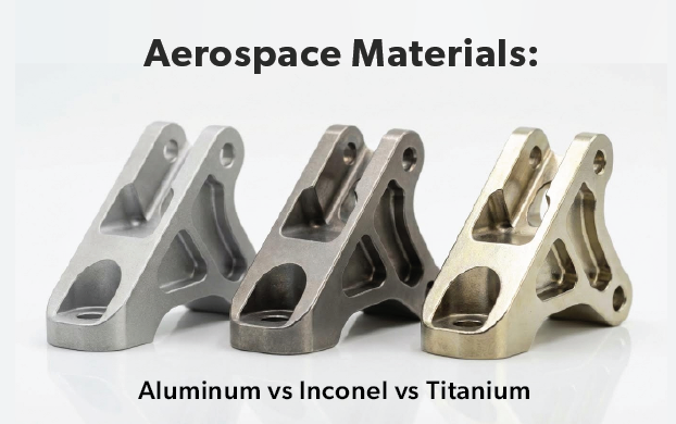
Pemilihan Paduan Aerospace dan Karakteristik Kemampuan Dibentuk
Ketika komponen pesawat terbang dibuat dari paduan aluminium, proses pemilihan material dimulai jauh sebelum operasi pembentukan dilakukan. Memilih paduan yang tepat bukan sekadar memilih opsi terkuat—melainkan menyesuaikan karakteristik kemampuan dibentuk, persyaratan perlakuan panas, serta tuntutan kinerja akhir dengan geometri komponen spesifik dan lingkungan operasionalnya.
Untuk Insinyur bekerja di bidang fabrikasi logam aerospace , memahami perilaku material selama operasi pembentukan membedakan proyek yang sukses dari kegagalan yang mahal. Setiap keluarga paduan—baik aluminium, titanium, maupun superpaduan berbasis nikel—menyajikan tantangan unik yang memerlukan pengetahuan khusus dan pengendalian proses yang cermat.
Pemilihan Paduan Aluminium untuk Aplikasi Struktural dan Kulit
Paduan aluminium tetap menjadi bahan utama untuk komponen lembaran logam pesawat terbang, menawarkan keseimbangan yang menarik antara kekuatan, berat, dan kemampuan pembentukan. Namun, tidak semua paduan aluminium berperilaku sama selama operasi pembentukan. Dua paduan aluminium aerospace yang paling umum ditentukan—2024 dan 7075—menggambarkan hal ini secara sempurna.
Paduan aluminium 2024 mengandung tembaga sebagai elemen paduan utamanya, yang memberikan ketahanan lelah dan toleransi kerusakan yang sangat baik. Hal ini menjadikannya ideal untuk kulit badan pesawat (fuselage skins) dan struktur sayap bagian bawah, di mana terjadi siklus tegangan berulang. Dari sudut pandang kemampuan pembentukan (formability), 2024 menawarkan kemudahan pengerjaan yang unggul dibandingkan alternatif berkekuatan lebih tinggi—material ini lebih mudah dibengkokkan, dibentuk, dan diformasi tanpa retak selama proses pengerjaan.
Sebaliknya, paduan aluminium 7075 memperoleh kekuatan luar biasanya dari penambahan seng, sehingga menjadikannya salah satu paduan aluminium paling kuat yang tersedia. Dengan kekuatan luluh melebihi 500 MPa dibandingkan sekitar 325 MPa pada 2024, 7075 unggul dalam aplikasi yang menuntut kapasitas penahan beban maksimum. Namun, kekuatan ini memiliki konsekuensi: 7075 jauh lebih sulit dibentuk dan dikerjakan dengan mesin. Kekerasannya memerlukan peralatan dan teknik khusus untuk mencegah terjadinya retak selama operasi pembentukan dingin.
Berikut adalah hal-hal yang dipahami oleh para insinyur berpengalaman mengenai pemilihan antara paduan-paduan ini:
- aluminium 2024 menawarkan kemampuan pembentukan yang lebih baik dan ketahanan yang unggul terhadap pertumbuhan retak lelah, sehingga lebih disukai untuk desain yang toleran terhadap kerusakan pada aplikasi kulit badan pesawat (fuselage) dan sayap (wing)
- 7075 Aluminium memberikan kekuatan statis yang lebih tinggi namun kemampuan pembentukannya berkurang—lebih cocok untuk aplikasi pelat tebal di mana pembentukan kompleks tidak diperlukan
- Kedua paduan memerlukan perlakuan panas larutan (solution heat treatment) dan penuaan (aging) untuk mencapai sifat optimal, namun respons keduanya terhadap proses termal berbeda secara signifikan
- Ketahanan korosi terbatas pada kedua paduan tersebut, sehingga umumnya memerlukan lapisan pelindung (cladding) atau perlakuan permukaan untuk aplikasi yang terpapar
Menurut Penelitian bahan dirgantara NASA , paduan seri 2xxx (seperti 2024) memiliki ketahanan toleransi kerusakan yang lebih baik dibandingkan paduan seri 7xxx. Hal ini menjelaskan mengapa paduan seri 2xxx biasanya ditentukan untuk aplikasi kritis terhadap retak (fracture-critical), sedangkan paduan seri 7xxx dicadangkan untuk komponen yang kritis terhadap kekuatan (strength-critical).
Bekerja dengan Titanium dan Superpaduan dalam Operasi Pengecoran
Ketika batas suhu aluminium menjadi kendala—biasanya di atas 150°C—paduan titanium dan superpaduan berbasis nikel masuk ke dalam gambar. Para spesialis perusahaan pembentuk logam eksotis ini menghadapi tantangan yang sama sekali berbeda dibandingkan dengan aluminium.
Daya tarik titanium di sektor dirgantara terletak pada rasio kekuatan-terhadap-beratnya yang luar biasa serta ketahanannya terhadap korosi. Ti-6Al-4V, paduan titanium yang paling banyak digunakan, menawarkan kekuatan tarik yang setara dengan banyak baja namun dengan kerapatan sekitar 60% dari baja. Namun, proses pembentukan titanium memerlukan pemahaman mendalam terhadap karakteristik uniknya:
- Titanium menunjukkan springback yang signifikan selama pembentukan dingin akibat kekuatannya yang tinggi dan modulus elastisitasnya yang relatif rendah
- Pembentukan panas pada kisaran suhu 540–815°C secara dramatis meningkatkan kemampuan bentuknya, tetapi memerlukan pengendalian atmosfer yang cermat guna mencegah kontaminasi oksigen
- Galling permukaan terjadi dengan mudah ketika titanium bersentuhan dengan peralatan cetak baja, sehingga memerlukan bahan die khusus atau lapisan pelindung
- Laju penguatan akibat deformasi (work hardening) sangat tinggi, sehingga membatasi jumlah deformasi yang dimungkinkan antar siklus anil
Paduan superberbasis nikel seperti Inconel 718 memperparah tantangan proses pembentukan. Material-material ini dirancang khusus untuk komponen mesin jet di mana suhu melebihi batas tahan suhu titanium maupun aluminium. Kekuatan luar biasa pada suhu tinggi—yang mempertahankan sifat mekanis di atas 550°C—menjadikannya esensial untuk disk turbin, liner ruang pembakaran, dan komponen knalpot.
Pembentukan Inconel menimbulkan kesulitan signifikan karena sifat-sifat yang menjadikannya unggul pada suhu tinggi justru menghambat deformasi pada suhu ruang. Pembentukan dingin sangat terbatas, dan sebagian besar komponen Inconel memerlukan pembentukan panas pada suhu tinggi dengan laju regangan yang dikontrol secara cermat.
| Jenis Paduan | Peringkat Kemampuan Bentuk | Aplikasi Tipikal | Persyaratan perlakuan panas | Tantangan Utama dalam Pembentukan |
|---|---|---|---|---|
| aluminium 2024 | Bagus sekali | Permukaan badan pesawat (fuselage skins), struktur sayap, anggota struktural | Perlakuan larutan + penuaan alami atau buatan (perlakuan temper T3, T4, T6) | Rentan terhadap korosi akibat tegangan; memerlukan pelapisan (cladding) untuk perlindungan korosi |
| 7075 Aluminium | Cukup | Permukaan atas sayap, sekat melintang (bulkheads), fitting, komponen struktural berkekuatan tinggi | Perlakuan larutan + penuaan; perlakuan temper T7 untuk meningkatkan ketahanan terhadap korosi akibat tegangan | Kemampuan deformasi dingin terbatas; rentan retak; ketahanan korosi lebih rendah dibandingkan 2024 |
| Ti-6Al-4V | Buruk (dingin) / Baik (panas) | Komponen mesin, perangkat pendaratan (landing gear), pengencang (fasteners), struktur badan pesawat (airframe structures) | Dilunakkan (annealed) atau diperlakukan larutan + dipenuakan; peredaan tegangan sangat krusial setelah proses pembentukan | Pemulihan elastis (springback) tinggi; terjadi galling dengan perkakas baja; memerlukan atmosfer inert untuk pembentukan panas |
| Inconel 718 | Sangat Buruk (dingin) / Cukup Baik (panas) | Cakram turbin, komponen ruang pembakaran, sistem knalpot, mesin roket | Perlakuan larutan pada suhu 940–1040°C + penuaan ganda untuk penguatan pengendapan | Pengerasan ekstrem akibat deformasi; memerlukan pembentukan panas pada suhu 870–1040°C; keausan alat signifikan |
| baja Tahan Karat 304/316 | Bagus sekali | Komponen knalpot, braket, pipa hidrolik, aplikasi kriogenik | Pelembutan untuk peredaan tegangan; pelembutan larutan untuk memulihkan ketahanan terhadap korosi | Pengerasan akibat deformasi selama proses pembentukan; manajemen springback; risiko sensitasi di zona terpengaruh panas |
Memahami karakteristik spesifik material ini sangat penting untuk memilih teknik pembentukan yang tepat—topik yang akan kami bahas lebih lanjut pada bagian berikutnya. Baik Anda bekerja dengan lembaran logam pesawat standar maupun superalloy eksotis, kesesuaian antara material dengan persyaratan komponen serta kemampuan pembentukan yang tersedia akan menentukan keberhasilan proyek.
Teknik Pembentukan Inti dan Kriteria Pemilihan Proses
Terkesan rumit? Sebenarnya tidak harus demikian. Memilih proses pembentukan yang tepat untuk komponen aerospace sering kali bergantung pada pemahaman terhadap tiga pendekatan dasar: stretch forming, hydroforming, dan metode konvensional. Namun, banyak insinyur kesulitan mengambil keputusan ini karena pesaing hanya menyebut teknik-teknik tersebut tanpa menjelaskan mekanisme di baliknya atau kapan masing-masing metode benar-benar unggul.
Kenyataannya, setiap proses menawarkan keunggulan khas untuk geometri, material, dan kebutuhan produksi tertentu. Memahami perbedaan-perbedaan ini membantu Anda menghindari kesalahan mahal—seperti memilih metode bervolume tinggi untuk produksi prototipe atau mencoba membentuk kurva kompleks dengan peralatan yang dirancang khusus untuk lengkungan sederhana.
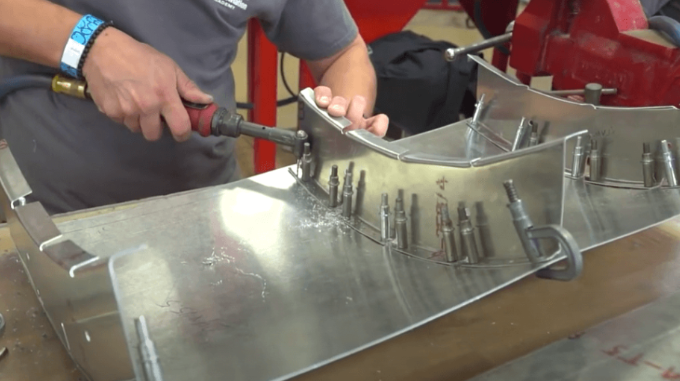
Mekanika dan Komponen Utama Stretch Forming
Pembentukan peregangan merupakan salah satu metode paling presisi untuk membuat profil melengkung kompleks pada bentuk lembaran logam. Selama proses ini, bahan—baik aluminium, titanium, maupun baja tahan karat—diregangkan melewati titik batas plastisnya dan secara bersamaan dibungkus di sekitar cetakan berbentuk akhir (net-shaped dies). Pendekatan ini pada dasarnya menggeser sumbu netral komponen ke tepi cetakan, sehingga menghasilkan kontur halus tanpa kerutan yang sangat akurat meniru bentuk cetakan.
Menurut Erie Press Systems , yang awalnya dikembangkan untuk produksi efisien profil melengkung kompleks di industri pesawat terbang, kini pembentukan peregangan secara luas digunakan untuk komponen serupa dalam aplikasi otomotif, dirgantara, konstruksi, kereta api, dan roket.
Apa yang membuat pembentukan peregangan lembaran logam menjadi sangat bernilai bagi sektor dirgantara? Pertimbangkan keunggulan utama berikut:
- Akurasi dimensi yang unggul: Komponen sangat akurat meniru bentuk cetakan dengan springback minimal dibandingkan operasi pembengkokan konvensional
- Manfaat pengerasan akibat deformasi plastis: Proses ini menyebabkan penguatan akibat deformasi pada banyak material, meningkatkan kekuatan sekaligus mengurangi tegangan sisa internal
- Kualitas permukaan bebas gores: Sebagian besar komponen yang dibentuk tidak memerlukan peningkatan dimensi maupun estetika setelah proses pembentukan
- Efisiensi Material: Komponen yang akurat dan dapat diulang dengan limbah material yang minimal mengurangi biaya keseluruhan per komponen
- Pengurangan proses pasca-pembentukan: Menghilangkan banyak operasi sekunder yang biasanya diperlukan untuk mencapai ketepatan dimensi
Mesin pembentuk regang diklasifikasikan ke dalam tiga kategori desain utama berdasarkan kebutuhan produksi. Mesin pembentuk regang lembaran menghasilkan komponen logam lembaran berbentuk lengkung kompleks, seperti panel eksterior dan tepi depan pada pesawat terbang serta roket komersial. Mesin pembentuk regang ekstrusi menangani komponen struktural dengan penampang melintang kompleks dan profil lengkung—misalnya stringer dan balok pendukung untuk pesawat terbang. Mesin berkecepatan tinggi dan berkapasitas tinggi umumnya dikhususkan untuk aplikasi otomotif atau produksi massal lainnya.
Namun, pembentukan regang bukan tanpa keterbatasan:
- Investasi peralatan: Mesin berkualitas tinggi dengan kontrol gerak yang tepat merupakan pengeluaran modal yang signifikan.
- Batas kecepatan: Jika proses pembentukan bergerak terlalu cepat, terutama pada bahan lembaran, garis Lüder (tanda permukaan) terjadi dari kontrol ketegangan yang tidak tepat
- Alat khusus yang dibutuhkan: Setiap geometry bagian yang unik membutuhkan mati khusus dan sisipan rahang diproduksi khusus untuk komponen itu
- Sensitivitas material: Beberapa jenis aluminium mengeras pada suhu kamar, yang membutuhkan pengolahan langsung dari tungku penggilingan sebelum pengerasan terjadi
Ketika memilih peralatan pembentuk peregangan, integritas struktural menjadi penting. Mesin dengan kepatuhan atau defleksi yang melekat tidak dapat memastikan ketegangan konstan dalam proses, sering menyebabkan produksi bagian yang tidak akurat atau tidak dapat diulang. Mesin konstruksi yang lebih ringan dengan rangka yang lemah atau tidak dirancang untuk penggunaan ruang angkasa yang diperpanjang.
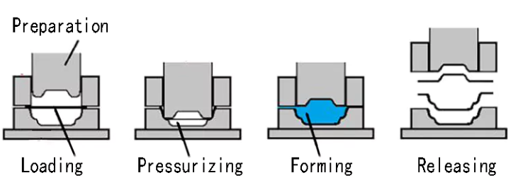
Hidroformasi vs Metode Konvensional untuk Geometri Kompleks
Ketika desain Anda memerlukan struktur berongga kompleks atau komponen melengkung dalam tiga dimensi, hidroformasi menawarkan kemampuan yang tidak dapat dicapai oleh proses stamping konvensional. Proses ini menggunakan cairan bertekanan tinggi—biasanya emulsi berbasis air—sebagai media transmisi gaya untuk membentuk lembaran logam di dalam rongga cetakan.
Perbedaan mendasarnya terletak pada cara gaya ditransmisikan ke material. Stamping konvensional menerapkan tekanan mekanis melalui pukulan dan die padat, sehingga memotong atau mendistorsi plastis lembaran logam melalui benturan langsung. Sebaliknya, hidroformasi menggunakan tekanan cairan untuk distribusi gaya yang seragam, memungkinkan pembentukan bentuk kompleks dengan jumlah operasi yang lebih sedikit.
Berikut adalah alasan mengapa hidroformasi menarik untuk aplikasi pembentukan logam di sektor dirgantara:
- Geometri kompleks dalam satu operasi: Tabung sederhana dapat berubah menjadi komponen berongga dengan kelengkungan tiga dimensi yang kompleks, diameter variabel, atau cabang berbentuk khusus dalam satu proses
- Pengelasan dan pemasangan berkurang: Membentuk terintegrasi menghilangkan sendi yang akan membutuhkan pengelasan dalam perakitan stamped multi-potongan
- Penggunaan material yang lebih baik: Proses ini menghasilkan hampir tidak ada limbah dibandingkan dengan material tepi dari stamping, mencapai tingkat pemanfaatan bahan melebihi 95%
- Kekuatan yang ditingkatkan melalui pengerasan kerja: Bagian yang dibentuk dengan air cenderung lebih kuat daripada kosong asli karena efek pengerasan kerja
- Kualitas permukaan yang lebih baik: Pembentukan cair menghindari goresan mati yang umum dalam percetakan mekanis, mengurangi operasi finishing sekunder
Menurut LS Precision Manufacturing, proses hydroforming hanya memerlukan separuh jumlah cetakan dibandingkan dengan stamping, sehingga menawarkan desain cetakan yang relatif sederhana dan investasi awal yang lebih rendah. Hal ini menjadikannya sangat cocok untuk aplikasi bervolume kecil hingga menengah dengan kompleksitas tinggi, yang umum ditemui dalam produksi aerospace.
Namun, stamping konvensional tetap memiliki keunggulan jelas dalam skenario tertentu:
- Kecepatan tak tertandingi untuk produksi massal: Stamping kontinu berkecepatan tinggi mampu mencapai puluhan hingga ratusan langkah per menit—ideal untuk komponen yang dibutuhkan dalam jumlah jutaan unit
- Efisiensi geometri sederhana: Untuk braket, komponen dengan drawing dangkal, atau elemen sheet metal dasar, cetakan stamping membentuk komponen secara cepat melalui proses blanking dan bending sederhana
- Kemampuan pengolahan sheet metal ultra-tipis: Stamping unggul dalam memproses sheet metal tipis dengan akurasi tingkat mikron melalui cetakan progresif
- Biaya per komponen terendah pada skala besar: Setelah biaya awal pembuatan perkakas (tooling) yang tinggi diangsur, komponen hasil stamping mencapai biaya satuan yang sangat rendah
Faktor kompatibilitas material memerlukan perhatian khusus saat memilih di antara metode-metode ini. Hidroformasi bekerja paling baik dengan logam yang memiliki daktilitas tinggi—baja tahan karat, paduan aluminium, dan baja karbon menunjukkan kinerja sangat baik, sedangkan paduan tembaga dan paduan titanium digunakan untuk aplikasi khusus. Material tersebut harus memiliki plastisitas yang cukup agar dapat mengalir bebas di bawah tekanan fluida tinggi dan mengambil bentuk rongga cetakan.
| Proses pembentukan | Geometri Komponen Terbaik | Kompatibilitas Materi | Kesesuaian Volume Produksi | Biaya Relatif |
|---|---|---|---|---|
| Stretch forming | Panel lembaran melengkung kompleks, tepi depan (leading edges), kulit luar (exterior skins), kontur berjari-jari besar | Paduan aluminium (sangat baik), titanium (pembentukan panas), baja tahan karat, paduan berkekuatan tinggi | Volume rendah hingga sedang; ideal untuk produksi komponen dirgantara | Biaya peralatan tinggi; biaya perkakas sedang; biaya per komponen rendah untuk kurva kompleks |
| Hidroformasi (Lembaran) | Cangkang berukuran sedang hingga besar dengan kurva kompleks, komponen dengan kedalaman tarikan dangkal, struktur terintegrasi | Baja tahan karat, paduan aluminium, baja karbon, paduan tembaga; memerlukan daktilitas yang baik | Volume kecil hingga sedang; biaya peralatan cetak 40–60% lebih rendah dibandingkan proses stamping | Investasi peralatan menengah; biaya peralatan cetak rendah; biaya per komponen sedang |
| Hydroforming (Tabung) | Komponen struktural berongga, penampang bervariasi, saluran mesin, penyangga badan pesawat | Tabung aluminium, tabung baja tahan karat, titanium (khusus); ketebalan dinding seragam sangat kritis | Volume kecil hingga sedang; sangat cocok untuk prototipe hingga produksi skala rendah | Biaya peralatan menengah; desain die tunggal mengurangi biaya peralatan cetak |
| Stamping Konvensional | Komponen logam lembaran sederhana, braket, bentuk tarik dangkal, blanko datar, komponen berketebalan tipis | Semua logam yang dapat dibentuk; sangat cocok untuk lembaran tipis (0,5–3 mm); telah terbukti efektif pada berbagai jenis material | Volume tinggi hingga sangat tinggi; ekonomis hanya ketika biaya peralatan dapat diamortisasi | Investasi peralatan tinggi; biaya per komponen terendah pada skala besar; waktu siklus cepat |
| Pembentukan press brake | Lengkungan angular, lengkungan sederhana, braket, rangka penutup, elemen struktural | Aluminium, baja, baja tahan karat, titanium dengan peralatan yang sesuai | Prototipe hingga volume menengah; sangat fleksibel untuk berbagai geometri | Biaya peralatan rendah; peralatan minimal; biaya per komponen sedang; bergantung pada operator |
Saat memilih proses Anda, pertimbangkan bahwa hidroforming umumnya lebih ekonomis untuk batch kecil dan komponen kompleks, sedangkan stamping menawarkan jalur termurah untuk produksi massal komponen sederhana. Namun, keputusan ini melampaui perbandingan biaya semata—persyaratan integritas struktural, spesifikasi permukaan akhir, serta waktu pengerjaan yang tersedia semuanya memengaruhi pilihan optimal.
Memahami dasar-dasar proses pembentukan ini mempersiapkan Anda menghadapi salah satu aspek paling menantang dalam manufaktur dirgantara: mengendalikan springback dan mengintegrasikan protokol perlakuan panas yang tepat guna mencapai akurasi dimensi pada komponen jadi.
Pengendalian Springback dan Integrasi Perlakuan Panas
Anda telah memilih paduan yang tepat dan memilih teknik pembentukan yang sesuai—namun di sinilah banyak operasi pembentukan logam & pembengkokan dirgantara mengalami masalah tak terduga. Springback, kecenderungan frustasi logam untuk kembali sebagian ke bentuk asalnya setelah proses pembentukan, dapat mengubah komponen yang didesain secara presisi menjadi limbah jika tidak diprediksi dan dikendalikan secara memadai.
Tantangan ini menjadi semakin kompleks ketika persyaratan perlakuan panas diperhitungkan. Pemrosesan termal yang memberikan kekuatan luar biasa pada paduan aerospace juga memengaruhi kemampuan bentuk (formability) dan stabilitas dimensi. Memahami bagaimana faktor-faktor ini saling berinteraksi sangat penting untuk mencapai komponen siap terbang yang memenuhi spesifikasi yang sangat ketat.
Memprediksi dan Mengkompensasi Springback Material
Ketika Anda meregangkan atau membengkokkan paduan aerospace, pemulihan elastis terjadi segera setelah tekanan pembentukan dilepaskan. Secara esensial, material tersebut "melenting kembali" menuju kondisi datarnya semula karena hanya serat-serat di bagian luar yang telah melampaui titik luluh. Bagian dalam material tetap mengalami deformasi elastis dan cenderung kembali ke keadaan semulanya.
Mengapa hal ini begitu penting dalam aplikasi dirgantara? Pertimbangkan bahwa panel kulit sayap yang memerlukan lengkungan 15 derajat justru mungkin perlu dibentuk hingga 18 atau 19 derajat untuk mencapai geometri akhir setelah terjadinya springback. Jika kompensasi ini salah, Anda menghadapi pembuatan ulang yang mahal—atau bahkan lebih buruk lagi, komponen yang dibuang dari paduan eksotis yang harganya ribuan dolar per lembar.
Beberapa faktor memengaruhi besarnya springback pada paduan dirgantara:
- Kekuatan Material: Paduan berkekuatan tinggi seperti aluminium 7075 menunjukkan springback yang lebih besar dibandingkan kelas 2024 yang lebih daktil—tegangan luluh yang lebih tinggi menyebabkan energi elastis yang tersimpan selama proses pembentukan menjadi lebih besar
- Jari-jari Lekukan: Jari-jari lengkung yang lebih kecil umumnya menghasilkan springback yang lebih kecil karena lebih banyak material melewati batas luluh, namun berisiko menyebabkan retak pada paduan yang kurang dapat dibentuk
- Ketebalan Bahan: Lembaran yang lebih tebal biasanya menunjukkan persentase springback yang lebih kecil, meskipun penyimpangan dimensi absolutnya mungkin meningkat
- Suhu pembentukan: Suhu tinggi menurunkan kekuatan luluh, sehingga mengurangi pemulihan elastis, tetapi memerlukan pengendalian atmosfer untuk bahan-bahan reaktif
- Orientasi butir: Arah penggulungan memengaruhi besarnya springback—pembentukan tegak lurus terhadap arah serat sering menghasilkan hasil yang berbeda dibandingkan pembentukan sejajar dengan arah serat
Menurut penelitian yang dipublikasikan dalam Jurnal Aeronautika Tiongkok , teknologi creep age forming (CAF) mengatasi tantangan springback dengan menggabungkan deformasi creep dan proses penuaan pengerasan (age hardening). Teknik canggih ini menawarkan keuntungan seperti tegangan sisa rendah, stabilitas dimensi sangat baik, serta kinerja layanan yang unggul. Namun, para peneliti mencatat bahwa "jumlah besar springback terjadi setelah pelepasan beban, yang menimbulkan tantangan dalam pembentukan bentuk akurat dan penyesuaian sifat komponen."
Strategi kompensasi yang telah terbukti efektif untuk operasi pembentukan logam tarik meliputi:
- Overbending empiris: Secara sistematis membentuk melebihi geometri target berdasarkan data springback spesifik material yang diperoleh dari sampel uji
- Prediksi berbasis FEA: Menggunakan analisis elemen hingga (finite element analysis/FEA) dengan model material yang akurat untuk mensimulasikan springback sebelum fabrikasi perkakas
- Koreksi perkakas secara iteratif: Menyesuaikan cetakan berdasarkan deviasi yang diukur dari komponen contoh pertama—biasanya memerlukan 2–3 iterasi untuk geometri yang kompleks
- Pemantauan Selama Proses: Menerapkan sensor untuk mengukur gaya pembentukan dan perpindahan aktual, sehingga memungkinkan penyesuaian secara waktu nyata
- Persentase peregangan terkendali: Mempertahankan pemanjangan material yang konsisten—operasi pembentukan dengan peregangan (stretch forming) di wilayah selatan umumnya menargetkan peregangan permanen sebesar 2–4% guna meminimalkan variasi springback
Protokol Perlakuan Panas Sebelum, Selama, dan Setelah Pembentukan
Perlakuan panas dan operasi pembentukan saling terkait erat dalam manufaktur dirgantara. Kondisi termal material sebelum pembentukan sangat memengaruhi kemudahan pengerjaannya, sedangkan perlakuan pasca-pembentukan menentukan sifat mekanis akhir. Kesalahan dalam urutan proses ini dapat mengakibatkan retaknya komponen, kekuatan yang tidak memadai, atau distorsi dimensi yang tidak dapat diterima.
Untuk paduan aluminium, perlakuan panas larutan melibatkan pemanasan bahan pada suhu tinggi—biasanya antara 440°C dan 527°C menurut panduan teknis Clinton Aluminum—diikuti dengan pendinginan cepat (quenching). Proses ini melarutkan unsur-unsur paduan ke dalam larutan padat, dan pendinginan cepat tersebut menjebak unsur-unsur tersebut dalam keadaan supersaturasi. Segera setelah proses quenching, bahan menjadi relatif lunak dan sangat dapat dibentuk.
Berikut adalah faktor waktu kritis yang sering diabaikan para insinyur: paduan aluminium yang dapat dikeraskan melalui penuaan mulai mengalami peningkatan kekuatan pada suhu ruang melalui penuaan alami (natural aging). Artinya, Anda hanya memiliki jendela waktu terbatas—kadang hanya beberapa jam—untuk menyelesaikan operasi pembentukan sebelum bahan menjadi terlalu keras untuk diproses lebih lanjut. Untuk komponen kompleks yang memerlukan beberapa tahap pembentukan, perlakuan anil antara (intermediate annealing) mungkin diperlukan.
Alur kerja perlakuan panas khas untuk komponen dirgantara yang telah dibentuk mengikuti urutan berikut:
- Verifikasi kondisi bahan masuk: Konfirmasi kondisi perlakuan panas saat ini dari bahan baku sesuai dengan persyaratan gambar dan cocok untuk operasi yang direncanakan— Spesifikasi PRC-2001 NASA menekankan bahwa "kondisi perlakuan panas saat ini harus diverifikasi sebelum melakukan perlakuan panas lanjutan apa pun"
- Perlakuan panas larut (jika diperlukan): Panaskan hingga suhu tahan (soak temperature) khusus paduan, tahan selama durasi yang ditentukan berdasarkan ketebalan material, kemudian quench secara cepat untuk mempertahankan unsur-unsur terlarut dalam larutan
- Lakukan operasi pembentukan: Selesaikan semua operasi bending, stretching, atau hydroforming saat material masih berada dalam kondisi solution-treated dengan kemampuan bentuk maksimum
- Peredaan tegangan (jika ditentukan): Terapkan pemanasan terkendali pada suhu biasanya 50°F di bawah suhu tempering, tahan cukup lama untuk mengurangi tegangan sisa tanpa memengaruhi kekerasan, kemudian dinginkan secara perlahan
- Penuaan buatan (pengerasan pengendapan): Panaskan hingga suhu penuaan dan tahan selama durasi yang ditentukan untuk mengendapkan fasa penguat di dalam matriks paduan
- Inspeksi dan verifikasi akhir: Konfirmasi kekerasan dan persyaratan dimensi melalui pengujian sesuai ASTM E18 untuk kekerasan serta metode inspeksi geometris yang berlaku
Langkah perelaksasian tegangan memerlukan perhatian khusus pada perakitan las dan komponen berbentuk kompleks. Menurut spesifikasi perlakuan panas NASA, perelaksasian tegangan setelah pengelasan "harus dilakukan sesegera mungkin setelah operasi pengelasan." Hal ini terutama berlaku untuk baja Kelas A dan Kelas B, meskipun persyaratan spesifik bervariasi tergantung kelas paduan dan tingkat kritisitas aplikasi.
Untuk titanium dan superalloy, perlakuan panas menjadi jauh lebih kompleks. Bahan-bahan ini sering memerlukan proses dalam atmosfer inert atau vakum guna mencegah kontaminasi oksigen pada suhu tinggi. Operasi pembentukan panas untuk Ti-6Al-4V umumnya dilakukan pada kisaran suhu 540–815°C, dengan perlakuan peredaan tegangan berikutnya yang sangat penting untuk stabilitas dimensi. Inconel 718 memerlukan perlakuan larut (solution treatment) pada suhu 940–1040°C diikuti oleh dua siklus penuaan (aging) guna mencapai pengerasan presipitasi yang optimal.
Memahami bagaimana kondisi bahan memengaruhi baik kemampuan bentuk (formability) maupun sifat mekanis akhir memungkinkan Anda merencanakan operasi secara strategis. Bentuklah komponen ketika bahan masih lunak; perkuatlah ketika geometrinya telah terkunci. Prinsip dasar ini menjadi panduan dalam pemrosesan logam lembaran (sheet metal) untuk aerospace yang sukses—dan juga menjadi landasan bagi pertimbangan kritis lainnya dalam desain peralatan (tooling) serta pengendalian kualitas permukaan.
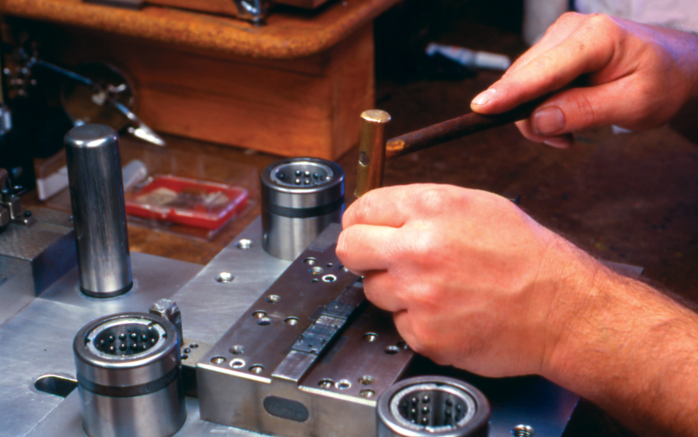
Desain Peralatan (Tooling) dan Persyaratan Kualitas Permukaan
Berikut adalah pertanyaan yang membedakan keberhasilan fabrikasi lembaran logam pesawat dari kegagalan mahal: mengapa komponen dirgantara memerlukan peralatan cetak (tooling) yang dianggap berlebihan di industri lain mana pun? Jawabannya terletak pada hubungan tak kenal ampun antara kualitas die (cetakan) dan integritas komponen. Ketika Anda membentuk lembaran logam pesawat yang ditujukan untuk aplikasi kritis penerbangan, setiap keputusan terkait peralatan cetak secara langsung memengaruhi akurasi dimensi, kualitas permukaan, dan—pada akhirnya—keselamatan terbang.
Berbeda dengan pembentukan otomotif atau industri umum di mana cacat permukaan kecil mungkin masih dapat diterima, komponen lembaran logam dirgantara harus memenuhi spesifikasi kualitas permukaan yang sangat ketat. Sebuah goresan atau bekas gesekan (gall mark) yang lolos inspeksi dalam manufaktur barang konsumen justru menjadi konsentrator tegangan yang berpotensi memicu retak lelah pada struktur pesawat. Kenyataan ini menuntut pendekatan khusus terhadap bahan die, perlakuan permukaan, serta sistem pelumas.
Pemilihan Bahan Perkakas untuk Permukaan Kelas Dirgantara
Bahan yang dipilih untuk cetakan pembentuk harus memenuhi dua tujuan kritis: mampu menahan penggunaan berulang tanpa terjadinya pergeseran dimensi akibat keausan, serta menghasilkan permukaan bebas cacat yang dapat mengganggu kinerja komponen. Menurut PEKO Precision Products, baja perkakas seperti baja karbon tinggi (A2, D2) atau baja paduan umumnya digunakan untuk cetakan karena kekerasan dan ketahanan ausnya.
Kekerasan bahan secara langsung berkorelasi dengan kinerja perkakas—bahan cetakan yang lebih keras mampu menahan tegangan pembentukan yang lebih besar, sehingga lebih cocok untuk aplikasi volume tinggi di mana keausan kumulatif mengancam akurasi dimensi. Namun, aplikasi dirgantara menambah lapisan kompleksitas lain: paduan eksotis yang dibentuk sering kali menimbulkan tantangan unik yang tidak dapat diatasi oleh baja perkakas standar.
Pertimbangkan hal-hal kritis berikut terkait perkakas saat menentukan spesifikasi cetakan untuk operasi pembentukan dirgantara:
- Persyaratan kekerasan cetakan: Baja perkakas harus mencapai kekerasan yang cukup (biasanya 58–62 HRC untuk operasi pembentukan) guna menahan deformasi akibat siklus pembebanan berulang, sekaligus mempertahankan kualitas hasil permukaan
- Lapisan Permukaan: Pelapisan krom, nitrida titanium (TiN), atau lapisan karbon mirip berlian (DLC) mengurangi gesekan dan mencegah lekatnya material—terutama penting saat membentuk paduan titanium atau aluminium yang rentan terhadap galling
- Interval perawatan: Tetapkan jadwal inspeksi berdasarkan jumlah komponen yang diproses dan tren pengukuran dimensi; sistem mutu aerospace umumnya mensyaratkan verifikasi terdokumentasi mengenai kondisi die sebelum menjalankan produksi
- Spesifikasi hasil akhir permukaan: Permukaan die sering kali memerlukan proses pemolesan hingga nilai Ra di bawah 0,8 mikrometer guna mencegah bekas transfer pada komponen yang dibentuk
- Stabilitas Termal: Die yang digunakan dalam operasi pembentukan panas harus mempertahankan stabilitas dimensi di seluruh kisaran suhu operasional, sekaligus tahan terhadap oksidasi dan kelelahan termal
Jarak bebas antara punch dan die memerlukan perhatian rekayasa yang cermat. Seperti dicatat PEKO, jarak bebas yang tepat bergantung pada jenis dan ketebalan material—jarak bebas yang terlalu kecil menyebabkan keausan alat berlebihan dan deformasi tepi, sedangkan jarak bebas yang terlalu besar menghasilkan gerinda (burr) dan kualitas tepi yang buruk. Untuk aplikasi dirgantara, toleransi ini menjadi bahkan lebih ketat karena tepi hasil bentukan sering harus bersambungan dengan struktur lain yang memerlukan kecocokan presisi.
Strategi Pelumasan untuk Mencegah Galling dan Cacat Permukaan
Galling merupakan salah satu mode kegagalan paling menjengkelkan dalam operasi pembentukan dirgantara. Menurut Coating Technologies Inc. , galling adalah bentuk keausan yang disebabkan oleh adhesi antara permukaan yang saling meluncur—gabungan gesekan dan adhesi diikuti oleh selip dan sobekan struktur kristal di bawah permukaan. Ketika terjadi galling, operasi pembentukan terhenti total karena perkakas dan benda kerja saling melekat.
Berikut ini yang membuat masalah ini khususnya bermasalah bagi industri dirgantara: logam-logam yang paling rentan terhadap galling juga merupakan logam yang paling umum digunakan dalam manufaktur penerbangan. Aluminium, titanium, dan baja tahan karat—material yang dihargai karena rasio kekuatan-terhadap-berat dan ketahanan terhadap korosi—semuanya menunjukkan kerentanan tinggi terhadap galling akibat struktur kristal atomiknya. Logam-logam ini dapat mengalami galling hanya dengan tekanan atau pergerakan yang sangat kecil dalam kondisi yang tepat.
Beberapa strategi pelumasan mengatasi tantangan ini:
- Pelumas film kering: Lapisan berbasis molibdenum disulfida atau PTFE yang diaplikasikan pada permukaan perkakas memberikan kelancaran pelumasan yang konsisten tanpa kekhawatiran kontaminasi dari pelumas cair
- Senyawa pembentuk yang larut dalam air: Pelumas ini menawarkan kekuatan film yang sangat baik selama proses pembentukan sekaligus memungkinkan penghilangan yang mudah melalui pembersihan berbasis air—hal ini sangat penting ketika proses lanjutan memerlukan permukaan yang bersih sempurna
- Lapisan khusus anti-galling: Lapisan nikel elektroles NP3 telah menjadi standar industri untuk mencegah terjadinya galling pada komponen aerospace berbahan stainless steel dan aluminium, menggabungkan ketahanan korosi dengan karakteristik pelumas mandiri
- Pemasangan bahan yang berbeda: Menggunakan bahan alat yang tidak mudah berikatan dengan paduan benda kerja dapat mengurangi potensi galling bahkan tanpa pelumasan tambahan
Pemilihan sistem pelumasan melampaui sekadar pencegahan galling. Pemilihan pelumas memengaruhi kualitas hasil permukaan, kebutuhan pembersihan pasca-pembentukan, serta kesesuaian dengan proses selanjutnya seperti pengelasan atau perekatan menggunakan perekat. Banyak spesifikasi aerospace membatasi jenis pelumas yang diperbolehkan dan mewajibkan prosedur pembersihan tertentu guna memastikan penghapusan total sebelum perakitan.
Pemeliharaan mati secara rutin memperparah pertimbangan pelumasan ini. Keausan progresif mengubah karakteristik gesekan antara alat dan benda kerja, sehingga berpotensi memerlukan penyesuaian pelumas selama masa pakai mati tersebut. Dokumentasi kegiatan pemeliharaan, nomor lot pelumas, serta temuan inspeksi menjadi bagian dari catatan kualitas komponen aerospace—menciptakan jejak terlacak (traceability) apabila suatu komponen yang dibentuk kemudian menunjukkan perilaku tak terduga selama penggunaan.
Setelah strategi peralatan dan pelumasan ditetapkan, tantangan berikutnya adalah memverifikasi bahwa komponen yang dibentuk benar-benar memenuhi spesifikasi dimensi. Standar presisi dan protokol jaminan kualitas menyediakan kerangka kerja bagi proses verifikasi kritis ini.
Standar Presisi dan Protokol Jaminan Kualitas
Anda telah membentuk komponen, mengendalikan springback, dan mempertahankan peralatan yang tepat—tetapi bagaimana cara membuktikan bahwa komponen tersebut benar-benar memenuhi spesifikasi? Di sinilah banyak layanan fabrikasi logam untuk sektor dirgantara gagal. Tanpa standar presisi ketat dan protokol verifikasi yang andal, bahkan operasi pembentukan yang dilakukan dengan baik pun dapat menghasilkan komponen dengan kualitas yang tidak pasti.
Insinyur dan profesional pengadaan membutuhkan data toleransi konkret untuk mengambil keputusan yang terinformasi. Namun, informasi ini justru sangat sulit ditemukan dalam bentuk terkonsolidasi. Toleransi yang dapat dicapai melalui berbagai proses pembentukan bervariasi secara signifikan tergantung pada jenis material, geometri komponen, dan kapabilitas peralatan. Memahami hubungan-hubungan ini—beserta metode inspeksi yang memverifikasi kesesuaian—membedakan pemasok yang memang berkualifikasi dari pemasok yang hanya mengklaim kemampuan di sektor dirgantara.
Toleransi Dimensi Berdasarkan Proses Pembentukan dan Material
Saat menentukan toleransi untuk komponen pesawat terbang dalam operasi stamping logam atau pembentukan, Anda akan memperhatikan bahwa presisi yang dapat dicapai sangat bergantung pada proses yang dipilih serta bahan yang dibentuk. Paduan yang lebih keras dengan springback yang lebih besar menimbulkan tantangan toleransi yang lebih ketat dibandingkan bahan yang lebih duktif. Demikian pula, geometri yang kompleks memerlukan pengendalian proses yang lebih canggih dibandingkan lipatan sederhana.
Menurut Re:Build Cutting Dynamics, toleransi manufaktur aerospace mewakili batas variasi yang dapat diterima dalam dimensi dan karakteristik komponen—toleransi ini bukan sekadar angka, melainkan persyaratan kritis yang secara langsung memengaruhi kinerja dan keamanan komponen. Setiap aspek spesifikasi suatu bagian harus dikendalikan secara cermat, mulai dari dimensi dasar hingga hasil permukaan (surface finish) dan sifat-sifat material.
Pertimbangkan bagaimana toleransi memengaruhi kinerja penerbangan sesungguhnya:
- Permukaan aerodinamis: Kontur permukaan dan pengendalian celah yang presisi secara langsung memengaruhi koefisien drag dan efisiensi bahan bakar
- Integritas Struktural: Distribusi beban yang tepat bergantung pada ketepatan pemasangan antar komponen yang saling berpasangan
- Ketahanan Sistem: Komponen bergerak memerlukan jarak bebas yang terjamin agar dapat berfungsi sepanjang masa pakai operasionalnya
- Kepatuhan Keamanan: Mempertahankan integritas struktural dan fungsional menuntut akurasi dimensi yang konsisten di seluruh proses produksi
| Proses pembentukan | Paduan Aluminium | Paduan titanium | Baja tahan karat | Paduan super nikel |
|---|---|---|---|---|
| Stretch forming | ±0,010" hingga ±0,030" | ±0,015" hingga ±0,045" | ±0,012" hingga ±0,035" | ±0,020" hingga ±0,060" |
| Hidroformasi (Lembaran) | ±0,008" hingga ±0,020" | ±0,012" hingga ±0,030" | ±0,010" hingga ±0,025" | ±0,015" hingga ±0,040" |
| Stamping Konvensional | ±0,005" hingga ±0,015" | ±0,010" hingga ±0,025" | ±0,008" hingga ±0,020" | ±0,012" hingga ±0,030" |
| Pembentukan press brake | ±0,015" hingga ±0,060" | ±0,025" hingga ±0,080" | ±0,020" hingga ±0,070" | ±0,030" hingga ±0,090" |
| Pemesinan CNC (Referensi) | ±0,0005 inci hingga ±0,005 inci | ±0.001" hingga ±0.005" | ±0,0005 inci hingga ±0,005 inci | ±0,001" hingga ±0,008" |
Perhatikan bagaimana paduan super titanium dan nikel secara konsisten menunjukkan rentang toleransi yang lebih lebar dibandingkan aluminium. Hal ini mencerminkan karakteristik springback (pemulihan elastis) yang lebih tinggi serta kesulitan dalam memprediksi pemulihan elastis pada material berkekuatan tinggi ini. Ketika proses manufaktur capps atau persyaratan presisi lainnya menuntut toleransi yang lebih ketat daripada yang dapat dicapai hanya melalui proses pembentukan saja, maka operasi pemesinan sekunder menjadi diperlukan—menambah biaya namun memastikan dimensi kritis memenuhi spesifikasi.
Mencapai Presisi yang Dapat Diulang dalam Lingkungan Produksi
Mencapai toleransi pada satu komponen saja tidak berarti banyak jika komponen-komponen berikutnya bergeser di luar spesifikasi. Pengulangan—kemampuan menghasilkan hasil yang identik di seluruh proses produksi—memerlukan pengendalian sistematis terhadap variabel-variabel yang memengaruhi hasil dimensi.
Manufaktur kedirgantaraan modern menuntut kemampuan pengukuran yang canggih. Menurut panduan manufaktur presisi Grup KESU, inspeksi CMM (Coordinate Measuring Machine / Mesin Pengukur Koordinat) menggunakan mesin pengukur koordinat untuk menilai karakteristik geometris suatu komponen, dengan CMM modern mampu mencapai akurasi hingga 0,5 mikron. Tingkat presisi ini memungkinkan verifikasi fitur-fitur yang tidak mungkin diukur menggunakan alat konvensional.
Tiga metode inspeksi utama digunakan untuk verifikasi pembentukan komponen kedirgantaraan:
- Inspeksi CMM: Sebuah probe bergerak sepanjang sumbu X, Y, dan Z untuk menyentuh atau memindai permukaan komponen, merekam koordinat titik-titik yang kemudian dibandingkan dengan model CAD asli. CMM tipe jembatan memberikan akurasi tertinggi untuk komponen kedirgantaraan berukuran besar, sedangkan CMM lengan portabel menawarkan fleksibilitas untuk pemeriksaan selama proses produksi.
- Pemindaian optik: Pengukuran tanpa kontak menggunakan sistem cahaya terstruktur atau laser menangkap keseluruhan geometri permukaan secara cepat—sangat ideal untuk permukaan melengkung kompleks di mana pengukuran titik demi titik dengan probe menjadi tidak praktis.
- Pemantauan Selama Proses: Pengukuran secara waktu nyata selama operasi pembentukan memungkinkan koreksi segera sebelum komponen selesai—sensor melacak gaya pembentukan, aliran material, dan perkembangan dimensi di sepanjang proses
Mempertahankan kondisi lingkungan yang konsisten terbukti sama pentingnya. Variasi suhu menyebabkan perubahan dimensi baik pada komponen maupun peralatan pengukuran. Kelembapan memengaruhi beberapa jenis material serta perilaku pelumas. Fasilitas bersertifikasi menjaga lingkungan terkendali—biasanya 20°C ±1,1°C dengan pengendalian kelembapan—baik untuk operasi pembentukan maupun inspeksi akhir.
Industri dirgantara menerapkan beberapa standar manufaktur paling ketat di antara semua sektor. Mencapai dan mempertahankan toleransi kelas dirgantara memerlukan pendekatan komprehensif yang mempertimbangkan kemampuan peralatan, pengendalian lingkungan, serta tantangan spesifik material.
Apa saja persyaratan sebenarnya dari sertifikasi AS9100 dan NADCAP untuk komponen yang dibentuk? Menurut dokumentasi sertifikasi KLH Industries, AS9100 sepenuhnya mengadopsi persyaratan ISO 9001 sekaligus menangani kebutuhan tambahan terkait kualitas dan keselamatan yang spesifik bagi industri dirgantara. Perusahaan wajib menyediakan dokumentasi, termasuk laporan inspeksi artikel pertama (first article inspection), sertifikat bahan, dan sertifikat kesesuaian (certificates of conformance), guna memenuhi persyaratan produsen peralatan dirgantara.
NADCAP melangkah lebih jauh dengan menstandarisasi proses-proses tertentu, bukan hanya sistem prosedural semata. Untuk operasi pembentukan (forming), hal ini berarti mengendalikan masukan (inputs) serta variabel-variabel potensial yang memengaruhi kualitas komponen. Akreditasi Nadcap mensyaratkan adanya sistem mutu yang sah dan telah tersertifikasi sesuai AS9100 atau setara sebagai prasyarat—menjamin bahwa pengendalian khusus proses tersebut dibangun di atas fondasi manajemen mutu yang komprehensif.
Beban dokumentasi untuk pembentukan aerospace tidak boleh diremehkan. Setiap lot material harus dapat dilacak hingga sertifikasi pabrik pengolahannya. Catatan perlakuan panas harus menunjukkan kepatuhan terhadap siklus termal yang ditentukan. Data inspeksi harus membuktikan bahwa setiap dimensi berada dalam batas toleransi. Dokumentasi ini memungkinkan analisis akar masalah ketika terjadi kendala dan menyediakan jejak audit yang dipersyaratkan regulator untuk perangkat keras kritis penerbangan.
Setelah standar presisi dan protokol kualitas ditetapkan, satu pertanyaan penting masih tersisa: apa yang terjadi ketika terjadi kegagalan? Memahami mode kegagalan umum beserta strategi pencegahannya membantu menjaga konsistensi kualitas yang menjadi tujuan sistem ketat ini.
Analisis Mode Kegagalan dan Pencegahan Cacat
Bahkan dengan pemilihan paduan yang tepat, peralatan yang dioptimalkan, dan sistem kualitas yang ketat, cacat tetap terjadi dalam operasi pembentukan di sektor dirgantara. Perbedaan antara produsen kelas dunia dan bengkel yang kesulitan sering kali terletak pada seberapa cepat mereka mengidentifikasi akar masalah serta menerapkan perbaikan yang efektif. Namun, pengetahuan kritis ini—yakni memahami mengapa komponen gagal dan bagaimana mencegah kejadian serupa di masa depan—secara mencolok tidak hadir dalam sebagian besar diskusi industri.
Baik Anda bekerja sama dengan perusahaan pembentukan regang (stretch forming) untuk panel melengkung kompleks maupun menjalankan stamping komponen pesawat secara internal, pengenalan pola kegagalan sebelum berkembang menjadi masalah sistemik dapat menghemat waktu dan biaya secara signifikan. Lebih penting lagi, deteksi dini cacat mencegah komponen tidak sesuai spesifikasi berlanjut ke operasi hilir yang mahal.
Cacat Pembentukan Umum dan Analisis Akar Masalah
Ketika komponen dirgantara yang telah dibentuk gagal dalam pemeriksaan, cacat yang terlihat hanya menceritakan sebagian dari keseluruhan masalah. Menurut dokumentasi teknis HLC Metal Parts, cacat umum pada proses stamping logam berasal dari enam penyebab utama: regangan berlebih, pemilihan material yang tidak tepat, alat potong yang tidak memadai, desain cetakan yang tidak wajar, parameter stamping yang tidak tepat, serta pelumasan yang tidak cukup. Memahami akar penyebab ini memungkinkan tindakan korektif yang tepat sasaran, bukan sekadar pemecahan masalah secara coba-coba.
Berikut adalah mode kegagalan yang paling sering ditemui dalam operasi pembentukan dirgantara:
- Retakan: Terjadi ketika logam mengalami tegangan tarik melebihi batas daktilitasnya, biasanya muncul di daerah lokal dengan regangan tinggi. Akar penyebabnya meliputi perubahan bentuk yang berlebihan, material yang mengandung terlalu banyak pengotor atau pori-pori, jari-jari lengkung yang terlalu tajam relatif terhadap ketebalan material, serta pengaturan tekanan atau kecepatan stamping yang tidak tepat
- Kerutan: Gelombang tidak teratur atau kerutan permukaan yang muncul pada lembaran tipis atau area melengkung ketika distribusi tegangan menjadi tidak merata. Hal ini terjadi ketika material berlebih menumpuk secara lokal selama proses pembentukan, sering kali disebabkan oleh tekanan penahan benda kerja (blank holder) yang tidak cukup atau geometri die yang tidak tepat
- Kulit jeruk: Penampilan permukaan bertekstur menyerupai kulit jeruk, yang disebabkan oleh struktur butir kasar menjadi terlihat setelah deformasi plastis signifikan. Hal ini menunjukkan kondisi material sebelum pembentukan yang tidak tepat atau regangan berlebih selama operasi
- Perubahan Dimensi: Penyimpangan progresif dari toleransi yang ditentukan sepanjang serangkaian produksi, umumnya disebabkan oleh keausan perkakas, efek ekspansi termal, atau ketidakonsistenan sifat material antar lot
- Regangan dan goresan permukaan: Abrasinya atau kerusakan berbentuk tidak teratur pada permukaan hasil pembentukan yang mengakibatkan terbukanya logam dasar, sehingga meningkatkan risiko korosi dan menciptakan potensi titik awal kelelahan (fatigue initiation sites)
- Variasi springback: Pemulihan elastis yang tidak konsisten antar komponen, sehingga pengendalian dimensi menjadi tidak dapat diprediksi—sering kali disebabkan oleh variasi sifat material atau ketidaksesuaian parameter pembentukan
Menurut panduan pemecahan masalah pembentukan dari The Fabricator , masalah kualitas material sering kali menjadi akar penyebab kegagalan pembentukan. Seperti dikemukakan oleh ahli Steve Benson, "Material berkualitas buruk dan murah tidak memiliki tempat dalam produksi komponen berkualitas tinggi tanpa kesalahan; penggunaannya justru pada akhirnya dapat menimbulkan biaya sangat tinggi, mengingat biaya kegagalan dan penggantian komponen." Bahkan ketika material memenuhi spesifikasi kimia, ketidakonsistenan dan masalah kualitas tetap dapat menyebabkan retak selama proses pembentukan yang tampak tak terjelaskan pada pandangan pertama.
Interaksi antar variabel proses membuat pemecahan masalah menjadi sangat menantang. Sebuah komponen yang terbentuk dengan sukses bulan lalu bisa tiba-tiba retak—bukan karena satu parameter berubah, melainkan karena pergeseran kecil pada beberapa faktor yang saling bersamaan mendorong kondisi melebihi batas yang dapat diterima. Analisis akar masalah yang efektif memerlukan pemeriksaan kondisi material, kondisi perkakas, dan parameter proses secara bersamaan, bukan secara terpisah.
Langkah Pencegahan untuk Menjaga Konsistensi Kualitas Komponen
Mencegah cacat jauh lebih murah dibandingkan mendeteksi dan memperbaikinya setelah terjadi. Pendekatan sistematis dalam pencegahan cacat mengatasi tiga faktor utama penyebabnya: parameter proses, kondisi material, dan keausan perkakas.
Untuk pengendalian parameter proses, pertimbangkan strategi-strategi terbukti berikut:
- Optimalkan parameter stamping: Sesuaikan kecepatan punch, suhu, dan tekanan guna memastikan logam mengalami tingkat regangan yang sesuai—kecepatan tinggi meningkatkan gaya bentur dan memperdalam bekas permukaan, sedangkan tekanan berlebih merusak integritas material
- Menerapkan pengendalian proses statistik: Memantau variabel kunci secara terus-menerus dan menetapkan batas kendali yang memicu intervensi sebelum komponen menyimpang dari toleransi
- Mendokumentasikan parameter pengaturan yang telah terbukti efektif: Mencatat parameter pengaturan awal yang berhasil untuk setiap nomor komponen, sehingga mengurangi variasi yang diakibatkan oleh penilaian operator selama pergantian produksi
- Memanaskan awal atau meregangkan awal bila diperlukan: Mengkondisikan logam sebelum proses pembentukan meningkatkan plastisitas dan mengurangi risiko retak pada paduan yang kurang dapat dibentuk
Verifikasi kondisi bahan mencegah banyak cacat bahkan sebelum proses pembentukan dimulai:
- Verifikasi sifat bahan masuk: Memastikan kondisi perlakuan panas, struktur butir, dan sifat mekanis sesuai dengan spesifikasi—jangan mengasumsikan kepatuhan hanya berdasarkan sertifikasi pabrik
- Mengendalikan kondisi penyimpanan: Melindungi paduan aluminium dari efek penuaan alami yang mengurangi kemampuan pembentukan; menjaga suhu dan kelembapan yang tepat untuk bahan-bahan sensitif
- Periksa adanya cacat yang sudah ada sebelumnya: Kontaminan permukaan, kerusakan tepi, atau inklusi internal pada bahan baku akan menjadi cacat yang diperparah pada komponen hasil pembentukan
Pemeliharaan peralatan mencegah penurunan kualitas akibat keausan:
- Tetapkan interval inspeksi: Jadwalkan pemeliharaan dasar berdasarkan pola keausan yang terdokumentasi, bukan berdasarkan periode waktu acak—berbagai jenis bahan dan geometri menyebabkan keausan peralatan dalam laju yang sangat berbeda
- Pantau tren dimensi: Lacak dimensi utama komponen dari waktu ke waktu untuk mendeteksi keausan cetakan secara bertahap sebelum batas toleransi dilampaui
- Jaga sistem pelumasan: Penerapan pelumas yang tepat mencegah terjadinya galling dan cacat permukaan sekaligus mengurangi keausan cetakan; verifikasi secara berkala kondisi dan cakupan pelumas
- Dokumentasikan kondisi peralatan: Ambil foto permukaan die dan catat pengukurannya pada setiap interval perawatan untuk menetapkan ekspektasi dasar serta mengidentifikasi pola keausan yang tidak normal
Ketika cacat tetap terjadi meskipun telah diterapkan langkah-langkah pencegahan, pemecahan masalah secara sistematis akan mempercepat penyelesaian. Mulailah dengan memastikan sertifikasi bahan sesuai dengan spesifikasi. Verifikasi kondisi perkakas dan riwayat perawatan terakhir. Tinjau catatan parameter proses guna mendeteksi penyimpangan dari pengaturan yang telah terbukti efektif. Sering kali, akar permasalahan menjadi jelas ketika ketiga aspek ini diperiksa secara bersamaan—misalnya, pergantian lot bahan, siklus perawatan yang terlewat, atau penyesuaian parameter yang dilakukan untuk mengkompensasi masalah di tahap proses sebelumnya.
Memahami mode kegagalan ini serta strategi pencegahannya memberikan fondasi bagi konsistensi kualitas. Namun, industri dirgantara terus berkembang, dengan teknologi-teknologi baru yang menawarkan kemampuan inovatif dalam mendeteksi, mencegah, dan memprediksi cacat pembentukan sebelum terjadinya.

Teknologi Baru dan Kemitraan Manufaktur
Seperti apa teknologi pembentukan dirgantara lima tahun dari sekarang? Jawabannya sudah mulai terwujud di fasilitas manufaktur canggih di seluruh dunia. Mulai dari optimalisasi proses berbasis kecerdasan buatan (AI) hingga sel pembentukan robotik yang beroperasi secara otonom, teknologi-teknologi yang sedang mengubah industri ini menjanjikan kemampuan yang sepuluh tahun lalu terasa mustahil.
Namun inovasi-inovasi ini tidak berdiri sendiri. Teknologi-teknologi tersebut saling menyatu menjadi proses pembentukan digital terintegrasi yang menghubungkan desain, simulasi, produksi, dan inspeksi dalam alur kerja yang mulus. Memahami tren-tren baru ini membantu para insinyur dan produsen mempersiapkan—serta memanfaatkan—generasi berikutnya dari kemampuan pembentukan logam presisi.
Paduan Berkekuatan Tinggi Lanjutan Memasuki Aplikasi Dirgantara
Palet bahan yang tersedia untuk manufaktur logam lembaran canggih terus berkembang. Menurut penelitian yang disoroti oleh Alltec Manufacturing, bahan canggih—termasuk komposit, keramik, dan paduan berkinerja tinggi—kini menawarkan rasio kekuatan-terhadap-berat yang luar biasa, yang sangat penting untuk meningkatkan kinerja dan efisiensi pesawat terbang. Bahan-bahan ini memungkinkan pesawat mencapai efisiensi bahan bakar yang lebih baik, jangkauan yang lebih jauh, serta kapasitas muatan yang lebih besar.
Beberapa inovasi bahan sedang mengubah persyaratan proses pembentukan:
- Paduan aluminium-litium generasi ketiga: Bahan-bahan ini memberikan penghematan berat sebesar 10–15% dibandingkan aluminium kedirgantaraan konvensional, sekaligus meningkatkan kekakuan—namun memerlukan modifikasi parameter pembentukan guna mengakomodasi perilaku deformasinya yang berbeda
- Komposit matriks keramik (CMC): Meskipun tidak dibentuk melalui proses logam lembaran konvensional, CMC semakin menggantikan komponen superpaduan yang dibentuk dalam aplikasi mesin bersuhu tinggi, sehingga mendorong proses pembentukan logam memasuki wilayah desain baru
- Formulasi titanium canggih: Varian paduan titanium baru menjanjikan peningkatan kemampuan pembentukan pada suhu yang lebih rendah, sehingga berpotensi mengurangi biaya dan kompleksitas operasi pembentukan panas
- Sistem material hibrida: Laminat serat-logam dan struktur hibrida lainnya menggabungkan lapisan logam yang telah dibentuk dengan penguatan komposit, sehingga memerlukan pembentukan yang presisi guna mempertahankan integritas antarmuka
Kemajuan material ini menciptakan tantangan sekaligus peluang. Insinyur pembentukan harus mengembangkan parameter proses dan pendekatan peralatan baru untuk perilaku paduan yang belum dikenal. Di saat yang bersamaan, peningkatan kemampuan pembentukan material membuka kemungkinan untuk geometri kompleks yang sebelumnya tidak praktis.
Proses Pembentukan Hibrida dan Integrasi Digital
Bayangkan sebuah operasi pembentukan di mana robot memanipulasi lembaran logam dari kedua sisi secara bersamaan, dipandu oleh algoritma kecerdasan buatan yang menyesuaikan parameter secara real-time berdasarkan umpan balik sensor. Ini bukan fiksi ilmiah—ini sudah terjadi. Menurut analisis Wevolver terhadap tren manufaktur, perusahaan seperti Machina Labs sedang menerapkan lengan robotik ganda bersumbu 7 yang bekerja secara sinkron, dengan satu robot menopang sisi belakang lembaran logam sementara robot lainnya menerapkan tekanan pembentukan.
Pendekatan robotik ini menawarkan keuntungan transformatif untuk aplikasi dirgantara:
- Penghapusan perkakas khusus desain: Karena robot dapat menyesuaikan gerakannya secara pemrograman, komponen pertama dapat diproduksi dalam hitungan jam hingga hari, bukan menunggu berminggu-minggu untuk cetakan khusus
- Operasi tanpa lampu secara terus-menerus: Sistem otomatis dapat beroperasi 24/7, secara signifikan meningkatkan laju produksi untuk kampanye manufaktur
- Fleksibilitas tanpa preseden: Pemrograman ulang cepat memungkinkan penyesuaian perubahan desain atau spesifikasi tanpa modifikasi peralatan fisik
- Presisi yang ditingkatkan melalui kecerdasan buatan: Algoritma pembelajaran mesin menganalisis data secara waktu nyata untuk mengoptimalkan parameter gaya, kecepatan, dan deformasi di setiap siklus pembentukan
Teknologi digital twin menambahkan dimensi lain pada transformasi ini. Sebagaimana ditunjukkan dalam kolaborasi antara Siemens dan Rolls-Royce yang dipamerkan di EMO 2025 , digital twin komprehensif memungkinkan kolaborasi tanpa hambatan di seluruh tahap desain, rekayasa, manufaktur, dan inspeksi kualitas. Dengan memusatkan data terkelola dalam ekosistem perangkat lunak terintegrasi, produsen dapat mengeksplorasi dan mengevaluasi berbagai variasi desain serta proses dalam jumlah tak terbatas sebelum beralih ke produksi fisik.
Hasilnya berbicara sendiri. Siemens melaporkan bahwa Co-Pilot CAM berbasis AI mereka mampu memangkas waktu pemrograman hingga 80% dengan menyarankan operasi pemesinan, peralatan, dan parameter yang optimal. Ketika dikombinasikan dengan simulasi mesin virtual yang memverifikasi keamanan dan bebas tabrakan sebelum produksi aktual, alat digital ini secara signifikan mengurangi siklus pengembangan dan risiko.
Untuk komponen aerospace, pendekatan rantai digital (digital thread) ini mencapai hasil luar biasa dalam demonstrator pompa Rolls-Royce: sebuah komponen yang 25% lebih ringan, 200% lebih kaku, serta memenuhi faktor keamanan sebesar 9 dibandingkan konsep awal. Peningkatan semacam ini hampir mustahil dicapai melalui pengembangan tradisional berbasis uji-coba.
Kemitraan Strategis dalam Manufaktur untuk Proyek Kompleks
Seiring kemajuan teknologi pembentukan aerospace yang semakin canggih, hanya sedikit organisasi yang mampu mempertahankan kemampuan mutakhir di seluruh proses dan jenis material. Kenyataan ini menjadikan kemitraan manufaktur strategis semakin bernilai—terutama ketika proyek menuntut prototipe cepat yang dikombinasikan dengan sistem kualitas siap produksi.
Pertimbangkan tantangan yang dihadapi para insinyur dalam mengembangkan komponen bentuk kompleks:
- Iterasi prototipe harus dilakukan secara cepat guna memenuhi jadwal program
- Umpan balik desain untuk kemudahan manufaktur diperlukan sejak dini—sebelum investasi peralatan mengunci geometri yang suboptimal
- Sertifikasi kualitas harus selaras dengan persyaratan industri aerospace dan otomotif
- Peningkatan skala produksi harus dilakukan tanpa mengorbankan presisi yang telah ditetapkan selama tahap pengembangan
Di sinilah keahlian lintas industri menjadi bernilai. Produsen yang melayani aplikasi otomotif yang menuntut tinggi mengembangkan kemampuan pembentukan logam presisi yang secara langsung dapat diterapkan pada persyaratan aerospace. Sebagai contoh, Shaoyi (Ningbo) Teknologi Logam menggabungkan prototipe cepat selama 5 hari dengan kemampuan produksi massal otomatis, yang didukung sertifikasi IATF 16949 yang menunjukkan penerapan sistem kualitas yang ketat. Dukungan DFM (Design for Manufacturability) komprehensif mereka membantu insinyur mengoptimalkan desain sebelum produksi—mengidentifikasi potensi masalah pembentukan sedini mungkin, ketika perubahan masih memerlukan biaya paling rendah.
Waktu balas penawaran dalam 12 jam yang menjadi ciri khas mitra manufaktur gesit memungkinkan siklus iterasi yang lebih cepat selama pengembangan. Ketika program dirgantara menuntut standar presisi yang sama diterapkan pada sasis otomotif, sistem suspensi, dan komponen struktural, menemukan mitra dengan keahlian terbukti lintas industri mempercepat keberhasilan proyek.
Kombinasi robot dan kecerdasan buatan merupakan masa depan industri pembentukan lembaran global. Dengan memilih bahan secara cermat, mengoptimalkan proses, serta berinvestasi pada perkakas dan perlengkapan khusus, produsen dapat mempercepat waktu produksi, mencapai presisi yang lebih tinggi, serta menyediakan produk berkualitas tinggi secara lebih konsisten.
Ke depan, konvergensi antara paduan canggih, otomatisasi berbasis kecerdasan buatan (AI), serta alur kerja digital terintegrasi akan terus mengubah batas kemungkinan dalam pembentukan logam lembaran untuk aerospace. Insinyur yang memahami kemampuan baru ini—dan membangun hubungan dengan mitra manufaktur yang mampu menyediakannya—akan paling siap memenuhi tuntutan program pesawat terbang dan pesawat luar angkasa generasi berikutnya.
Pertanyaan yang Sering Diajukan Mengenai Pembentukan Logam Lembaran untuk Aerospace
1. Apa itu pembentukan logam lembaran untuk aerospace dan bagaimana perbedaannya dengan pembentukan industri?
Pembentukan lembaran logam untuk aerospace melibatkan pembentukan, pemotongan, dan perakitan bahan logam secara presisi menjadi komponen siap terbang untuk pesawat terbang dan pesawat luar angkasa. Berbeda dengan pembentukan industri pada umumnya, aplikasi aerospace menuntut penggunaan paduan canggih seperti titanium dan aluminium berkualitas tinggi yang memiliki rasio kekuatan-terhadap-berat luar biasa. Toleransi diukur dalam perseribu inci, dan komponen harus mampu menahan perubahan suhu ekstrem, getaran intens, serta gaya aerodinamis selama puluhan tahun masa pakai. Sertifikasi seperti AS9100 mengharuskan pengendalian kualitas yang sangat ketat, jauh melampaui standar manufaktur umum.
2. Material apa saja yang umum digunakan dalam fabrikasi logam lembaran dirgantara?
Bahan-bahan paling umum meliputi paduan aluminium (2024 untuk ketahanan terhadap kelelahan pada kulit badan pesawat, 7075 untuk kekuatan maksimum pada komponen struktural), paduan titanium seperti Ti-6Al-4V untuk aplikasi suhu tinggi, serta superpaduan berbasis nikel seperti Inconel 718 untuk komponen mesin jet. Setiap bahan menimbulkan tantangan unik dalam hal kemampuan dibentuk—aluminium menawarkan sifat kerja yang baik, titanium memerlukan pembentukan panas pada kisaran suhu 540–815°C, dan Inconel membutuhkan proses pada suhu tinggi akibat karakteristik pengerasan akibat deformasi yang sangat ekstrem.
3. Apa saja teknik utama pembentukan lembaran logam di bidang dirgantara?
Tiga teknik utama mendominasi proses pembentukan di bidang dirgantara: pembentukan regang (stretch forming) menciptakan profil lengkung kompleks dengan meregangkan material melewati titik luluhnya sambil membungkusnya di sekitar cetakan, sehingga menghasilkan kontur bebas kerutan dengan springback minimal. Pembentukan hidrolik (hydroforming) menggunakan cairan bertekanan tinggi untuk membentuk struktur berongga kompleks dalam satu operasi tunggal, sehingga mengurangi kebutuhan pengelasan. Penstampingan konvensional unggul dalam produksi volume tinggi untuk geometri yang lebih sederhana. Pemilihan proses bergantung pada geometri komponen, jenis material, volume produksi, dan pertimbangan biaya.
4. Bagaimana produsen mengendalikan springback dalam operasi pembentukan dirgantara?
Pengendalian springback memerlukan pemahaman terhadap perilaku pemulihan elastis spesifik material. Strategi yang telah terbukti meliputi pembengkokan berlebih secara empiris berdasarkan data uji material, prediksi berbasis FEA menggunakan model material yang akurat, koreksi alat secara iteratif melalui pengukuran pada contoh pertama (first-article), serta mempertahankan peregangan permanen yang konsisten sebesar 2–4% dalam operasi pembentukan dengan peregangan (stretch forming). Paduan berkekuatan tinggi seperti aluminium 7075 menunjukkan springback yang lebih besar dibandingkan paduan yang lebih ulet, sehingga memerlukan kompensasi yang lebih agresif. Waktu perlakuan panas sangat krusial—paduan yang dapat dikeraskan melalui penuaan (age-hardenable alloys) harus dibentuk secara cepat setelah perlakuan larut (solution treatment), sebelum pengerasan alami mengurangi kemampuan bentuknya.
5. Sertifikasi kualitas apa saja yang diperlukan untuk pembentukan lembaran logam (sheet metal forming) di bidang dirgantara?
Sertifikasi AS9100 sangat penting, karena mencakup persyaratan ISO 9001 sekaligus memenuhi kebutuhan kualitas dan keselamatan khusus aerospace. Akreditasi NADCAP menstandarkan proses-proses tertentu dan mensyaratkan sistem manajemen mutu yang telah tersertifikasi AS9100 sebagai prasyarat. Produsen wajib menyediakan laporan inspeksi artikel pertama, sertifikat bahan, serta sertifikat kesesuaian. Setiap lot bahan harus dapat dilacak hingga sertifikasi pabrik pengolah (mill certifications), catatan perlakuan panas (heat treatment) harus menunjukkan kepatuhan terhadap standar, dan data inspeksi harus membuktikan kesesuaian dimensi—sehingga tercipta jejak audit yang lengkap untuk perangkat keras kritis penerbangan.