 छोटे पर्चे, उच्च मानदंड। हमारी तेजी से प्रोटोटाइपिंग सेवा मान्यता को तेजी से और आसानी से बनाती है —

शीट मेटल स्टैम्पिंग डाई के रहस्य: डिज़ाइन की कमियों से लेकर निर्दोष भागों तक
शीट मेटल स्टैम्पिंग डाई क्या है और यह क्यों महत्वपूर्ण है
क्या आपने कभी सोचा है कि निर्माता हज़ारों एक जैसे धातु के भागों का तीव्र सटीकता के साथ उत्पादन कैसे करते हैं ? इसका उत्तर एक विशिष्ट उपकरण में छिपा है, जो आधुनिक धातु कार्यकरण के केंद्र में स्थित होता है। धातु स्टैम्पिंग क्या है और इसे संभव बनाने वाली डाइज़ को समझना, ऑटोमोटिव पैनलों से लेकर छोटे-छोटे इलेक्ट्रॉनिक घटकों तक के पीछे के रहस्य को उजागर करता है।
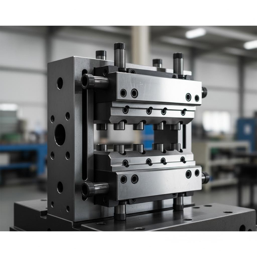
शीट मेटल स्टैम्पिंग डाई एक परिशुद्धता उपकरण है जिसे कठोरीकृत टूल स्टील से बनाया जाता है और जो स्टैम्पिंग प्रेस द्वारा लगाए गए नियंत्रित दबाव के माध्यम से समतल धातु की चादरों को काटता, आकार देता और विशिष्ट त्रि-आयामी भागों में रूपांतरित करता है।
तो, डाईज़ (dies) वास्तव में क्या हैं? उत्पादन में, स्टैम्पिंग डाईज़ (stamping dies) विशिष्ट उपकरण हैं जो शीट धातु पर निश्चित कटिंग और फॉर्मिंग ऑपरेशन करने के लिए डिज़ाइन किए गए हैं। ये एक जोड़े के रूप में काम करते हैं — एक ऊपरी और एक निचला घटक — जो विशाल बल के अधीन एक साथ आते हैं, ताकि कच्चे पदार्थ को तैयार भागों में परिवर्तित किया जा सके। हैंड टूल्स या सामान्य उद्देश्य के उपकरणों के विपरीत, ये डाईज़ एक विशिष्ट भाग ज्यामिति के लिए इंजीनियर्ड किए गए हैं और एक स्टैम्पिंग प्रेस की शक्ति के बिना उनका कार्य करना संभव नहीं है।
धातु निर्माण में स्टैम्पिंग डाईज़ का मुख्य कार्य
व्यावहारिक रूप से स्टैम्पिंग क्या है? यह एक ठंडा फॉर्मिंग प्रक्रिया है जिसमें धातु को पहले गर्म किए बिना डाईज़ का उपयोग करके आकार दिया जाता है। जब आप पूछते हैं कि स्टैम्प्ड धातु क्या है, तो आप इस सटीक यांत्रिक परिवर्तन के माध्यम से निर्मित घटकों को देख रहे हैं। अनुसार द फीनिक्स ग्रुप , एक स्टैम्पिंग डाई ऑपरेशन के दौरान चार महत्वपूर्ण कार्य करती है:
- स्थान निर्धारण - शीट धातु को डाई के भीतर सटीक रूप से स्थित करना
- क्लैम्पिंग - फॉर्मिंग के दौरान सामग्री को स्थिर रखना
- कार्यशील - वास्तविक कटिंग, बेंडिंग या शेपिंग ऑपरेशन करना
- मुक्त करना - तैयार भाग को मोल्डिंग से मुक्त करना
कार्य करने की अवस्था वह स्थान है जहाँ वास्तविक चमत्कार घटित होता है। इस चरण के दौरान, डाई मूल्य-वर्धित कार्यों जैसे कटिंग, बेंडिंग, पियर्सिंग, एम्बॉसिंग, फॉर्मिंग, ड्रॉइंग, स्ट्रेचिंग, कॉइनिंग और एक्सट्रूडिंग को करती है। प्रत्येक कार्य समतल ब्लैंक को किसी अधिक जटिल और उपयोगी वस्तु में परिवर्तित करता है।
डाइज़ उच्च-मात्रा उत्पादन के हृदय क्यों हैं
कल्पना कीजिए कि आप एक ऑटोमोटिव असेंबली लाइन के लिए 10,000 समान ब्रैकेट्स को हाथ से बना रहे हैं। इसमें अनंत समय लगेगा, और स्थिरता लगभग असंभव होगी। यही कारण है कि निर्माण में डाइज़ का इतना महत्व है।
उचित औजारों के बिना एक स्टैम्पिंग ऑपरेशन क्या है? सरल शब्दों में कहें तो — अक्षम और व्यावहारिक नहीं। जैसा कि डायनामिक डाई सप्लाई द्वारा उल्लेखित है, स्टैम्पिंग डाइज़ बड़े पैमाने पर सस्ते, उच्च-परिशुद्धता वाले भागों के उत्पादन को संभव बनाते हैं, जिनकी गुणवत्ता और आयामी सटीकता स्थिर रहती है। हालाँकि इन औजारों के विकास के लिए कंप्यूटर-सहायित डिज़ाइन और कुशल शिल्प कौशल में महत्वपूर्ण निवेश की आवश्यकता होती है, फिर भी उत्पादन मात्रा के आधार पर प्रारंभिक लागत के औचित्य के बाद ये अत्यंत मूल्यवान सिद्ध होते हैं।
शीट मेटल स्टैम्पिंग डाई की वास्तविक शक्ति दोहराव क्षमता में निहित है। एक बार उचित रूप से डिज़ाइन और निर्मित हो जाने के बाद, यह चक्र दर चक्र एक जैसे भागों का उत्पादन कर सकती है — कभी-कभी प्रति मिनट 1,000 से अधिक स्ट्रोक की गति से चलते हुए। गति, परिशुद्धता और स्थिरता का यह संयोजन स्टैम्पिंग डाइज़ को एयरोस्पेस से लेकर उपभोक्ता इलेक्ट्रॉनिक्स तक के उद्योगों में अपरिहार्य बनाता है।
पंचन (स्टैम्पिंग) डाई के प्रकार और प्रत्येक का उपयोग कब करना चाहिए
अब जब आप समझ गए हैं कि एक स्टैम्पिंग मर क्या करता है, अगला सवाल बन जाता हैः कौन सा प्रकार आपके प्रोजेक्ट के अनुरूप है? गलत प्रकार का मोल्ड चुनने का मतलब हो सकता है कि बजट बर्बाद हो, उत्पादन में देरी हो, या ऐसे भाग जो विनिर्देशों को पूरा नहीं करते हैं। आइए हम प्रमुख प्रकार के स्टैम्पिंग डाई को तोड़ें और पता करें कि वास्तविक दुनिया के निर्माण के लिए प्रत्येक का सबसे अधिक अर्थ कब है।
उच्च गति निरंतर उत्पादन के लिए प्रगतिशील मर जाता है
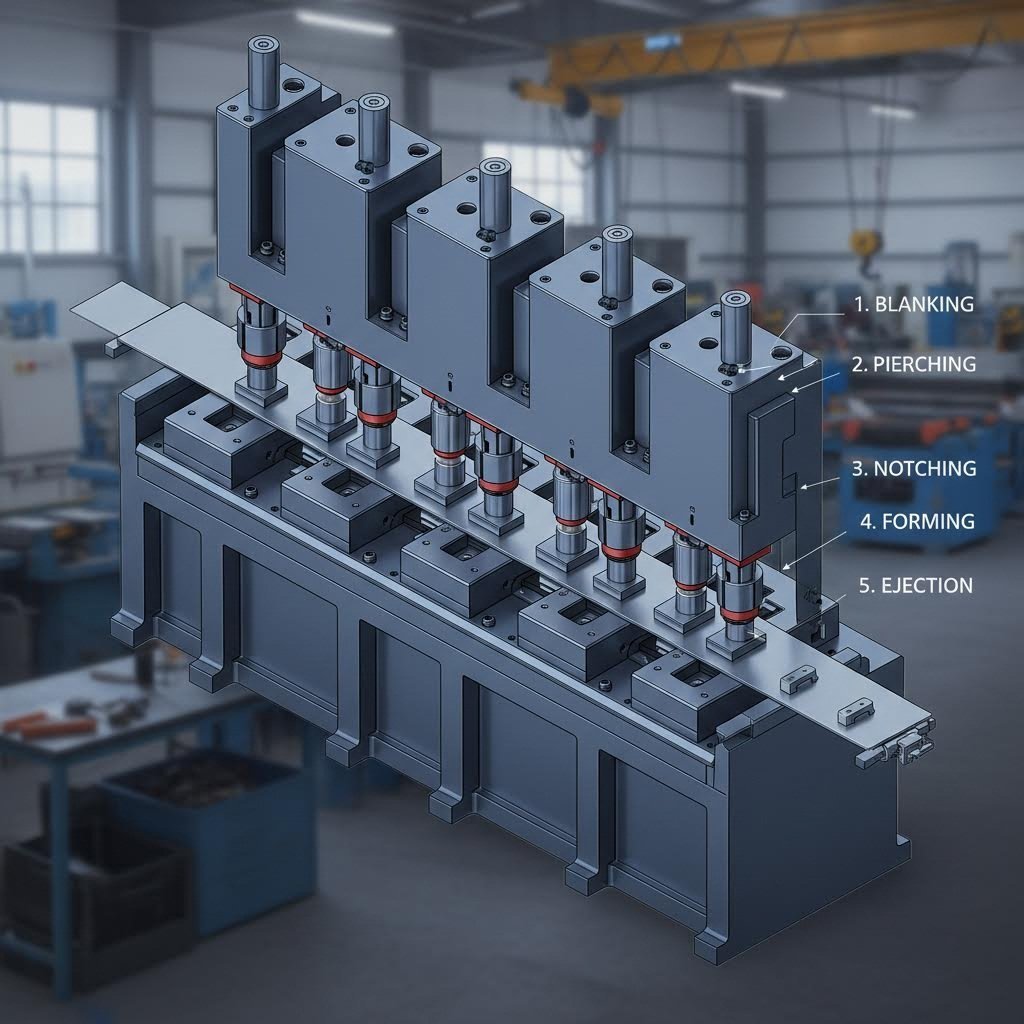
एक धातु के कॉइल एक प्रेस के माध्यम से लगातार खिला कल्पना करें जबकि कई स्टेशनों एक साथ काम कर रहे हैं - कि है क्रिया में प्रगतिशील मर मुद्रण . ड्यूरेक्स इंक के अनुसार, प्रगतिशील मोल्ड में कई स्टेशन होते हैं जो क्रम में व्यवस्थित होते हैं, जिनमें से प्रत्येक एक विशिष्ट ऑपरेशन करता है क्योंकि धातु शीट प्रेस के माध्यम से आगे बढ़ती है।
इस स्टैम्पिंग डाई कॉन्फ़िगरेशन को इतना शक्तिशाली बनाने वाला क्या है? कार्य-टुकड़ा प्रक्रिया की शुरुआत से अंत तक आधार स्ट्रिप से जुड़ा रहता है। वाहक स्ट्रिप से व्यक्तिगत भागों को अलग करना केवल अंतिम स्टेशन पर होता है। यह निरंतर प्रवाह संचालनों के बीच हैंडलिंग समय को समाप्त कर देता है और उत्पादन क्षमता को अधिकतम करता है।
प्रग्रेसिव डाइज़ किन परिस्थितियों में उत्कृष्ट प्रदर्शन करती हैं?
- उच्च मात्रा उत्पादन - हज़ारों या लाखों समान भागों के उत्पादन के लिए उपयुक्त
- सरल चरणों के माध्यम से जटिल ज्यामितियाँ - प्रत्येक स्टेशन एक संचालन को संभालता है, जिससे जटिलता क्रमिक रूप से बढ़ती है
- कठोर सहिष्णुता विनिर्देश - निरंतर स्ट्रिप पूरी प्रक्रिया के दौरान संरेखण को बनाए रखती है
- तेज़ साइकिल टाइम्स - भागों का उत्पादन तीव्र गति से और उच्च पुनरावृत्ति के साथ किया जाता है
हालाँकि, प्रग्रेसिव डाइज़ के लिए स्थायी स्टील टूलिंग में महत्वपूर्ण प्रारंभिक निवेश की आवश्यकता होती है। इन्हें गहरी ड्रॉइंग संचालन के लिए भी उपयुक्त नहीं माना जाता है, जहाँ रूपांतरण की गहराई जुड़ी हुई स्ट्रिप द्वारा समायोजित की जा सकने वाली सीमा से अधिक होती है।
जटिल भाग निर्माण में ट्रांसफर डाइज़ बनाम कंपाउंड डाइज़
जब प्रोग्रेसिव डाई (डाई) आवश्यकताओं के अनुरूप नहीं होती हैं, तो निर्माता आमतौर पर ट्रांसफर डाई और कॉम्पाउंड डाई के बीच चयन करते हैं। इनके अंतर को समझना आपको अपने विशिष्ट अनुप्रयोग के लिए दबाव मशीन (प्रेस) के लिए उचित डाई का चयन करने में सहायता करता है।
ट्रांसफर डाइ स्टैम्पिंग यह पहले ही संचालन में भाग को धातु की पट्टी से अलग कर देता है। इसके बाद, यांत्रिक "उंगलियाँ" प्रत्येक व्यक्तिगत भाग को कई स्टेशनों के माध्यम से ले जाती हैं, जहाँ अलग-अलग संचालन किए जाते हैं। इंजीनियरिंग स्पेशल्टीज इंक. के अनुसार, यह विधि नख़र, उभार और थ्रेडिंग जैसे जटिल डिज़ाइन तत्वों वाले भागों के लिए आदर्श है।
ट्रांसफर डाई निम्नलिखित परिस्थितियों में उत्कृष्ट प्रदर्शन करती है:
- गहरी ड्रॉ कॉम्पोनेंट्स, जहाँ फॉर्मिंग की गहराई पट्टी की सीमाओं से अधिक होती है
- ट्यूब अनुप्रयोग और जटिल असेंबलियाँ
- ऐसे भाग जिन पर कई ओरों पर संचालन की आवश्यकता होती है
- बड़े घटक जिन्हें प्रोग्रेसिव डाई द्वारा कुशलतापूर्ण रूप से संभाला नहीं जा सकता
चक्रवत डाइ स्टैम्पिंग पूरी तरह से अलग दृष्टिकोण अपनाता है। स्टेशनों के पार कई स्ट्रोक्स के बजाय, कंपाउंड डाइज़ एकल स्ट्रोक में सभी कटिंग, पंचिंग और बेंडिंग ऑपरेशन करते हैं। इससे ये सरल भागों के लिए अत्यधिक तीव्र हो जाते हैं। वर्थी हार्डवेयर के अनुसार, कंपाउंड डाइज़ वॉशर जैसे समतल भागों के मध्यम से उच्च मात्रा में उत्पादन के लिए विशेष रूप से लागत-प्रभावी होते हैं।
इसका सौदा-विकल्प? कंपाउंड डाइज़ जटिल त्रि-आयामी आकृतियों को संभाल नहीं सकते हैं। ये तब सर्वोत्तम प्रदर्शन करते हैं जब भाग की ज्यामिति अपेक्षाकृत सरल और समतल बनी रहती है।
डाइज़ प्रकारों की तुलना: एक व्यावहारिक चयन गाइड
अपनी अगली परियोजना के लिए फॉर्मिंग डाइज़ का मूल्यांकन करते समय, कई कारक यह निर्धारित करते हैं कि कौन-सा प्रकार सर्वोत्तम परिणाम प्रदान करेगा। डाइज़ और स्टैम्पिंग प्रक्रियाओं को आपकी भाग आवश्यकताओं, बजट और उत्पादन लक्ष्यों के साथ संरेखित होना चाहिए। निम्नलिखित तुलना मुख्य चयन मानदंडों को विस्तार से समझाती है:
| डाइ टाइप | खंड जटिलता | उत्पादन मात्रा | सेटअप समय | विशिष्ट अनुप्रयोग |
|---|---|---|---|---|
| प्रगतिशील डाइ | मध्यम से उच्च (क्रमिक रूप से निर्मित) | उच्च मात्रा (हज़ारों से लाखों तक) | प्रारंभिक लागत मध्यम; त्वरित परिवर्तन | ऑटोमोटिव ब्रैकेट्स, क्लिप्स, इलेक्ट्रॉनिक घटक |
| ट्रांसफर डाई | उच्च (जटिल डिज़ाइन, गहरी ड्रॉ) | छोटे से लंबे रन (लचीला) | लंबा सेटअप; सटीक संरेखण की आवश्यकता | एयरोस्पेस पार्ट्स, भारी मशीनरी, ट्यूब के घटक |
| चक्रव्यूह डाइ | निम्न से मध्यम (केवल समतल भाग) | माध्यम से उच्च मात्रा | त्वरित सेटअप; एकल-स्ट्रोक संचालन | वॉशर, गैस्केट, सरल समतल घटक |
| कॉम्बिनेशन डाई | मध्यम (कटिंग और फॉर्मिंग दोनों एक साथ) | मध्यम मात्रा | मध्यम सेटअप जटिलता | ऐसे भाग जिन्हें एक ही प्रेस चक्र में ब्लैंकिंग और फॉर्मिंग दोनों की आवश्यकता होती है |
इन चार प्राथमिक श्रेणियों के अतिरिक्त, ब्लैंकिंग डाई, कॉइनिंग डाई और एम्बॉसिंग डाई जैसे विशिष्ट डाई लक्षित कार्यों के लिए उपयोग किए जाते हैं। ब्लैंकिंग डाई शीट धातु से विशिष्ट आकृतियाँ काटते हैं, जो एक पूर्वतैयारी चरण के रूप में कार्य करता है। कॉइनिंग डाई गहने या चिकित्सा उपकरणों के लिए उच्च-परिशुद्धता वाले विस्तृत घटकों का निर्माण करते हैं। एम्बॉसिंग डाई सौंदर्य या कार्यात्मक उद्देश्यों के लिए उभरे हुए या धंसे हुए पैटर्न जोड़ते हैं।
उचित विकल्प का अंतिम निर्णय भाग की जटिलता और उत्पादन अर्थव्यवस्था के बीच संतुलन पर निर्भर करता है। उच्च-मात्रा वाले सरल भागों के लिए संयुक्त या प्रगतिशील दृष्टिकोण अधिक उपयुक्त होते हैं, जबकि जटिल संयोजनों के लिए ट्रांसफर डाई की लचीलापन लाभदायक होता है। इन अंतरों को समझना आपको अगले महत्वपूर्ण विचार—अर्थात् डाई के निर्माण में प्रयुक्त सामग्री और घटकों—के लिए तैयार करता है।
स्टैम्पिंग डाई के घटक और सामग्री का चयन
आपने अपनी परियोजना के लिए सही डाई प्रकार का चयन किया है — लेकिन वास्तव में उस टूलिंग के अंदर क्या होता है? स्टैम्पिंग डाई के घटकों को समझना उन इंजीनियरों को अलग करता है जो समस्याओं का निवारण करते हैं, और उन लोगों से जो उन्हें पूरी तरह से रोकते हैं। आइए एक विशिष्ट धातु स्टैम्पिंग डाई को काटकर उन महत्वपूर्ण भागों की जाँच करें जो यह निर्धारित करते हैं कि आप दोषरहित भाग बनाते हैं या लगातार गुणवत्ता संबंधी समस्याओं से जूझते रहते हैं।
पंच से स्ट्रिपर प्लेट तक आवश्यक डाई घटक
एक धातु डाई एक सटीक रूप से इंजीनियर्ड असेंबली के रूप में जहाँ प्रत्येक घटक का एक विशिष्ट उद्देश्य होता है। यू-नीड के स्टैम्पिंग डाई घटकों के मार्गदर्शिका के अनुसार, व्यक्तिगत भागों का डिज़ाइन, सामग्री और अखंडता कुल उपकरण प्रदर्शन और संचालन आयु के 90 प्रतिशत से अधिक को निर्धारित करती है।
ये वे मुख्य घटक हैं जो अधिकांश शीट धातु डाइज़ में पाए जाते हैं:
- डाई शू (ऊपरी और निचली) - डाई सेट के ऊपरी और निचले आधे हिस्सों को बनाने वाली भारी बेस प्लेटें। निचली शू प्रेस बेड पर माउंट की जाती है, जबकि ऊपरी शू रैम से जुड़ती है। ये सभी घटकों को संरेखण में रखने के लिए संरचनात्मक आधार प्रदान करती हैं।
- गाइड पिन और बुशिंग - एक डाई शू पर सटीक रूप से ग्राइंड किए गए कठोर पिन, जो दूसरी डाई शू पर समान रूप से सटीक बुशिंग में सरकते हैं। ये प्रत्येक प्रेस स्ट्रोक के दौरान ऊपरी और निचले आधे हिस्सों के बीच पूर्ण संरेखण सुनिश्चित करते हैं।
- पंच - छेदन, ब्लैंकिंग या फॉर्मिंग संचालन करने वाले पुरुष घटक। ये सीधे कार्य-टुकड़े (वर्कपीस) के संपर्क में आते हैं और संचालन के दौरान सबसे अधिक तनाव का सामना करते हैं।
- डाई बटन - कटिंग संचालनों में पंच के महिला समकक्ष। प्रत्येक बटन पर पंच प्रोफाइल के मिलान वाला सटीक रूप से ग्राइंड किया गया छिद्र होता है, जिसमें विशिष्ट क्लीयरेंस अनुमतियाँ शामिल होती हैं।
- स्ट्रिपर प्लेटें - छेदन या ब्लैंकिंग के बाद पंचों से सामग्री को निकालने के लिए आवश्यक। उचित स्ट्रिपिंग बल के बिना, भाग टूलिंग से चिपक जाते हैं और उत्पादन रुक जाता है।
- बैकिंग प्लेट्स - पंच और डाई बटन के पीछे स्थित कठोर प्लेटें जो प्रभाव बलों को अवशोषित करती हैं और उपकरण के विक्षेपण को रोकती हैं।
- पायलट - सटीक पिन जो प्रत्येक स्टेशन पर स्ट्रिप सामग्री की सही स्थिति निर्धारित करते हैं, विशेष रूप से प्रग्रेसिव स्टील स्टैम्पिंग डाई में यह अत्यंत महत्वपूर्ण है।
किसी भी घटक में कुछ माइक्रोमीटर की छोटी सी त्रुटि भी विफलताओं की एक श्रृंखला को ट्रिगर कर सकती है: गलत भाग आयाम, उपकरण का शीघ्र घिसावट, महंगी अनियोजित बंद-अवधि और उच्च अपशिष्ट दरें। यही कारण है कि प्रत्येक भाग के कार्य को समझना इतना महत्वपूर्ण है।
स्थायित्व और परिशुद्धता के लिए सामग्री चयन
कुछ धातु निर्माण डाई 500,000 चक्र तक चलते हैं, जबकि अन्य 50,000 चक्र पर ही विफल हो जाते हैं—इसका कारण क्या है? सामग्री चयन अक्सर निर्णायक कारक होता है। प्रत्येक स्टैम्प डाई घटक के लिए उचित टूल स्टील या विशेष मिश्र धातु का चयन करने के लिए कठोरता, टैफनेस (आघात प्रतिरोध), घिसावट प्रतिरोध और तापीय स्थिरता के बीच संतुलन स्थापित करना आवश्यक होता है।
न्यूवे के उपकरण एवं डाई सामग्री मार्गदर्शिका के अनुसार, प्रत्येक गुण निम्नलिखित योगदान करता है:
- कठोरता - सामान्य पंचन के लिए उपकरण इस्पात की कठोरता 44–52 HRC (रॉकवेल कठोरता) होनी चाहिए, या मांग वाले ठंडे कार्य अनुप्रयोगों के लिए 60 HRC तक हो सकती है
- दृढ़ता - दोहराव वाले यांत्रिक प्रभाव के दौरान चिपिंग और दरारों से सुरक्षा प्रदान करता है; जटिल डाई के लिए चार्पी V-नॉटिस मान 20 J से अधिक वांछनीय हैं
- प्रतिरोध पहन - यह निर्धारित करता है कि कटिंग एज़ और फॉर्मिंग सतहें अपनी ज्यामिति को कितने समय तक बनाए रखती हैं
- आयामी स्थिरता - कम विकृति वाली सामग्री ऊष्मा उपचार के बाद सटीकता बनाए रखती हैं; आयतनिक सिकुड़न 0.3% से कम होना आमतौर पर स्वीकार्य है
पंचन डाई घटकों में उपयोग की जाने वाली सामान्य सामग्रियाँ इनमें से हैं:
| सामग्री | कठोरता रेंज | सर्वश्रेष्ठ उपयोग | मुख्य फायदे |
|---|---|---|---|
| डी2 टूल स्टील | 58-62 HRC | ब्लैंकिंग डाई, ट्रिम डाई, पतली शीट धातु कटिंग | उच्च क्रोमियम सामग्री (~12%) उत्कृष्ट घर्षण प्रतिरोध प्रदान करती है |
| A2 उपकरण इस्पात | 56-60 HRC | सामान्य उद्देश्य की डाई, फॉर्मिंग उपकरण, इंसर्ट्स | अच्छी आयामी स्थिरता और संतुलित टफनेस |
| एस7 टूल स्टील | 54–56 HRC | ट्रिम डाईज़, प्रभाव-गहन अनुप्रयोग | भंगुरता के बिना अद्वितीय प्रभाव प्रतिरोध |
| टंगस्टन कार्बाइड | >80 HRC | उच्च-घर्षण प्रतिरोधी इन्सर्ट्स, लंबे जीवन वाले काटने वाले उपकरण | अत्यधिक संपीड़न सामर्थ्य और घर्षण प्रतिरोध का दीर्घ जीवन |
| H13 हॉट वर्क स्टील | 44–52 HRC | उच्च तापमान के संपर्क में आने वाले डाईज़ | सामर्थ्य, टैफनेस और ताप प्रतिरोध का उत्कृष्ट संतुलन |
D2 टूल स्टील को अपनी अद्वितीय क्षरण प्रतिरोध क्षमता के कारण ठंडे कार्य स्टैम्पिंग परिचालनों के लिए एक लोकप्रिय विकल्प के रूप में बनाए रखा गया है। हालाँकि, यह उच्च-प्रभाव अनुप्रयोगों के लिए आवश्यक टैफनेस की कमी से ग्रस्त है। दोहराव वाले झटका भार का सामना करने वाले घटकों के लिए, S7 स्टील कम कठोरता संख्याओं के बावजूद श्रेष्ठ प्रदर्शन प्रदान करती है।
कार्बाइड इन्सर्ट्स उच्च गुणवत्ता वाले विकल्प को दर्शाते हैं, जबकि डाई की आयु इस निवेश को औचित्यपूर्ण ठहराती है। यद्यपि ये टूल स्टील की तुलना में अधिक भंगुर होते हैं, कार्बाइड घटक अपने स्टील विकल्पों की तुलना में अपघर्षक स्टैम्पिंग अनुप्रयोगों में 5 से 10 गुना अधिक समय तक चलते हैं। कई निर्माता कार्बाइड का रणनीतिक रूप से उपयोग करते हैं — इस महँगी सामग्री से पूरे घटकों का निर्माण न करके, बल्कि केवल उच्च-घर्षण वाले स्थानों पर ही इन्सर्ट्स लगाकर।
टाइटेनियम नाइट्राइड (TiN) या डायमंड-लाइक कार्बन (DLC) जैसी विशिष्ट लेपन प्रक्रियाएँ घर्षण को कम करके और सतह की कठोरता में सुधार करके टूल के जीवन को और अधिक बढ़ाती हैं। ये उपचार विशेष रूप से तब अत्यंत उपयोगी सिद्ध होते हैं, जब स्टेनलेस स्टील, एल्यूमीनियम या अन्य गैलिंग के प्रवण धातुओं को स्टैम्प किया जा रहा हो।
प्राप्त करने योग्य सहिष्णुताएँ घटकों के पदार्थों और डाई के विन्यास दोनों पर भारी मात्रा में निर्भर करती हैं। उद्योग मानकों के अनुसार, परिशुद्धि-पॉलिश किए गए घटक +/- 0.001 मिमी की सहिष्णुता बनाए रख सकते हैं, जबकि मानक टूलिंग आमतौर पर +/- 0.025 मिमी या उससे ढीली सहिष्णुता पर काम करती है। प्रगतिशील डाइज़ (प्रोग्रेसिव डाइज़) एकल-स्टेशन सेटअप की तुलना में सामान्यतः अधिक कड़ी सहिष्णुताएँ प्राप्त करती हैं, क्योंकि निरंतर स्ट्रिप प्रसंस्करण के समय पूरी अवधि में स्थिर स्थिति बनाए रखती है।
घटकों और पदार्थों को समझने के बाद, अगला तार्किक कदम इन जटिल असेंबलियों के इंजीनियरों द्वारा डिज़ाइन किए जाने के तरीके की जांच करना है — प्रारंभिक CAD मॉडल से लेकर सिमुलेशन-सत्यापित उत्पादन टूलिंग तक।
डाई डिज़ाइन प्रक्रिया: अवधारणा से उत्पादन तक
आपने सही डाई प्रकार का चयन किया है और संबंधित सामग्रियों को समझ लिया है — लेकिन एक स्टैम्पिंग डाई डिज़ाइन वास्तव में जीवंत कैसे होती है? प्रारंभिक अवधारणा से उत्पादन-तैयार टूलिंग तक की यात्रा में उन्नत सॉफ़्टवेयर, सावधानीपूर्ण विश्लेषण और पुनरावृत्तिक शोधन शामिल होते हैं। इस डाई प्रक्रिया को सही ढंग से निष्पादित करना यह निर्धारित करता है कि आपकी पहली उत्पादन चलाने पर आदर्श भाग प्राप्त होंगे या महंगा कचरा।
सीएडी मॉडल से उत्पादन-तैयार डाई डिज़ाइन तक
आधुनिक धातु स्टैम्पिंग डाई डिज़ाइन तब शुरू होती है जब कोई धातु अभी तक मशीन नहीं की गई होती है। स्टैम्पिंग प्रक्रिया डिजिटल रूप से शुरू होती है, जिसमें इंजीनियर भाग की ज्यामिति को एक संरचित कार्यप्रवाह के माध्यम से निर्माण योग्य टूलिंग में बदलते हैं।
सामान्य डिज़ाइन अनुक्रम इन चरणों का अनुसरण करता है:
- भाग विश्लेषण - इंजीनियर समाप्त भाग की ज्यामिति की जाँच करते हैं, जिसमें फॉर्मिंग आवश्यकताओं, महत्वपूर्ण आयामों और संभावित समस्या क्षेत्रों की पहचान की जाती है
- प्रक्रिया योजना - भाग के उत्पादन के लिए ऑपरेशनों के क्रम, स्टेशनों की संख्या और समग्र डाई कॉन्फ़िगरेशन का निर्धारण करना
- ब्लैंक विकास - न्यूनतम अपव्यय के साथ अंतिम ज्यामिति के रूप में बनने वाले आदर्श समतल पैटर्न के आकार और आकृति की गणना करना
- डाई लेआउट - डाई सेट के भीतर पंच, फॉर्मिंग सतहों और सामग्री हैंडलिंग सुविधाओं की समग्र व्यवस्था बनाना
- विवरण डिजाइन - पंच, डाई बटन, स्ट्रिपर्स और गाइड प्रणालियों सहित व्यक्तिगत घटकों का इंजीनियरिंग करना
- CAM प्रोग्रामिंग - डाई घटकों के सीएनसी मशीनिंग के लिए टूलपाथ उत्पन्न करना
सीएडी/कैम एकीकरण ने इस कार्यप्रवाह को कैसे संभाला जाता है, इस पर इंजीनियरों के दृष्टिकोण को बदल दिया है। आज के डिज़ाइन प्लेटफॉर्म 3डी ठोस मॉडल से सीधे मशीनिंग निर्देशों तक बिना किसी मैनुअल डेटा अनुवाद के सुगम संक्रमण की अनुमति देते हैं। पैरामेट्रिक मॉडलिंग त्वरित डिज़ाइन पुनरावृत्तियों को सक्षम करती है — सीएडी मॉडल में एक पंच का व्यास बदलें, और संबंधित सभी घटक स्वतः अपडेट हो जाएँगे।
एक निर्माण डाई डिज़ाइन को वास्तव में उत्पादन-तैयार क्यों माना जाता है? ज्यामितीय सटीकता के अतिरिक्त, इंजीनियरों को सामग्री के स्प्रिंगबैक, प्रेस विक्षेपण, तापीय प्रसार और घिसावट की अनुमति को ध्यान में रखना आवश्यक है। ये कारक शायद ही कभी पाठ्यपुस्तकों के उदाहरणों में प्रकट होते हैं, लेकिन वास्तविक दुनिया के टूलिंग प्रदर्शन को प्रभावित करने वाले प्रमुख कारक हैं।
सिमुलेशन कैसे महंगी डिज़ाइन त्रुटियों को रोकता है
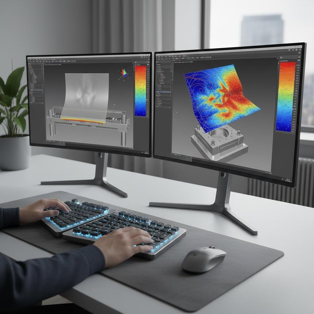
कल्पना कीजिए कि आपके नव-मशीन किए गए टूलिंग झुर्रियों वाले भाग उत्पन्न कर रहे हैं—जबकि निर्माण पर सप्ताहों और हज़ारों डॉलर का खर्च कर चुके हैं। यह परिदृश्य सिमुलेशन सॉफ़्टवेयर के आने से पहले स्टैम्पिंग डाई डिज़ाइन को क्रांतिकारी बनाने के पहले नियमित रूप से घटित होता था।
के अनुसार डटन सिमुलेशन , प्रेस टूल सिमुलेशन का उपयोग 1990 के आरंभ से व्यापक रूप से किया जा रहा है, जिसका एक स्पष्ट लक्ष्य है: "धातु के ढलाई से पहले ही फटने, झुर्रियों, पतलापन, सतह दोषों और स्प्रिंगबैक समस्याओं की भविष्यवाणी करके डाई डिज़ाइन प्रक्रिया से अनिश्चितता को समाप्त करना।" NUMISHEET जैसे अंतर्राष्ट्रीय मानकों ने बार-बार इन विधियों की सटीकता की पुष्टि की है।
आधुनिक CAE (कंप्यूटर-सहायित इंजीनियरिंग) सिमुलेशन उन महत्वपूर्ण मुद्दों की पहचान करता है जो अन्यथा केवल भौतिक प्रयासों के दौरान ही उभरेंगे:
- स्प्रिंगबैक भविष्यवाणी - जैसा कि कीज़ाइट की इंजीनियरिंग टीम स्पष्ट करती है, उन्नत उच्च-सामर्थ्य इस्पात और एल्यूमीनियम मिश्र धातुएँ फॉर्मिंग के बाद महत्वपूर्ण स्थितिज पुनर्प्राप्ति प्रदर्शित करती हैं। सिमुलेशन इस व्यवहार की भविष्यवाणी करता है, जिससे इंजीनियर निर्माण से पहले टूलिंग ज्यामिति में समायोजन कर सकते हैं।
- झुर्रियों का विश्लेषण - संपीड़न क्षेत्रों में अतिरिक्त सामग्री के कारण झुर्रियाँ बनती हैं, जो भाग की गुणवत्ता को नष्ट कर देती हैं। सिमुलेशन यह प्रकट करता है कि कहाँ ब्लैंकहोल्डर दबाव में समायोजन या ऐडेंडम ज्यामिति में परिवर्तन इन दोषों को रोक सकते हैं।
- पतलापन और फटने का जोखिम - अत्यधिक आक्रामक खींचने से सामग्री की मोटाई स्वीकार्य सीमा से परे पतली हो जाती है, जिससे अंततः फटने की संभावना होती है। सिमुलेशन पूरे भाग की सतह पर मोटाई वितरण का मानचित्रण करता है।
- सतह गुणवत्ता मूल्यांकन - दृश्य घटकों के लिए, सिमुलेशन डिजिटल स्टोनिंग कंटूर्स या वर्चुअल लाइटरूम विश्लेषण के माध्यम से सौंदर्य गुणवत्ता का मूल्यांकन कर सकता है, जो शॉपफ्लोर निरीक्षण तकनीकों की नकल करता है।
एटा/डायनाफॉर्म और फास्टफॉर्म एडवांस्ड जैसे सॉफ्टवेयर पैकेज डाई निर्माण अनुप्रयोगों के लिए वर्तमान कला की स्थिति का प्रतिनिधित्व करते हैं। ये उपकरण विस्तृत परिमित तत्व मॉडलों को शामिल करते हैं, जो ब्लैंकहोल्डर वक्रता, ड्रॉबीड ज्यामिति, स्नेहन स्थितियों, और यहां तक कि एक ही बैच के भीतर सामग्री गुणों में परिवर्तनों को भी ध्यान में रखते हैं।
सिमुलेशन के लिए व्यावसायिक आधार मजबूत है। भौतिक डाई ट्रायआउट्स में प्रेस का सप्ताहों तक समय लगता है, कुशल तकनीशियनों की आवश्यकता होती है, और अक्सर कई सुधार चक्रों की आवश्यकता होती है। आभासी ट्रायआउट्स इस समय-रेखा को काफी कम कर देते हैं, जबकि वे ऐसी समस्याओं की पहचान करते हैं जिन्हें भौतिक परीक्षण पूरी तरह से याद कर सकते हैं। जैसा कि कीसाइट नोट करता है, सिमुलेशन डिज़ाइन के प्रारंभिक चरण में "दोषों की पूर्वानुमान और रोकथाम करने में सहायता करता है, जिससे संचालन को सरल बनाया जाता है और यह सुनिश्चित किया जाता है कि भाग प्रारंभ से ही कठोर गुणवत्ता मानकों को पूरा करें।"
शायद सबसे मूल्यवान वस्तु प्रत्यास्थ प्रतिक्रिया के लिए संकल्पना समायोजन है — जिसमें उपकरण की सतहों को आंशिक-स्वचालित रूप से सामग्री की प्रत्यास्थ पुनर्प्राप्ति के प्रभाव को कम करने के लिए समायोजित किया जाता है। सिमुलेशन के बिना, इंजीनियर अनुभव-आधारित नियमों पर निर्भर करते हैं, जो विभिन्न सामग्रियों और ज्यामितियों के लिए असंगत रूप से कार्य करते हैं। सिमुलेशन के साथ, यह समायोजन व्यवस्थित और भविष्यवाणी योग्य बन जाता है, जिससे पुनरावृत्ति चक्रों की संख्या कई से कम होकर कुछ हो जाती है।
पुनरावृत्तिकरण द्वारा सुधार की प्रक्रिया आमतौर पर इस पैटर्न का अनुसरण करती है: प्रारंभिक डिज़ाइन का सिमुलेशन करना, दोषों की पहचान करना, टूलिंग ज्यामिति या प्रक्रिया पैरामीटर में संशोधन करना, पुनः सिमुलेशन करना, और तब तक दोहराना जब तक परिणाम विनिर्देशों को पूरा नहीं कर लेते। प्रत्येक आभासी चक्र में घंटों का समय लगता है, जबकि भौतिक पुनरावृत्तियों के लिए दिनों या सप्ताह की आवश्यकता होती है। यह त्वरण परियोजना की अर्थव्यवस्था को मौलिक रूप से बदल देता है — एक ही समयसीमा और बजट के भीतर अधिक डिज़ाइन खोज को सक्षम बनाता है।
सिमुलेशन क्षमताओं को समझना आपको स्टैम्पिंग संचालन में अगले महत्वपूर्ण संबंध के लिए तैयार करता है: अपने डाई डिज़ाइन को प्रेस उपकरण विनिर्देशों के साथ मिलाना।
धातु स्टैम्पिंग ऑपरेशन में प्रेस और डाई का संबंध
आपने एकदम सही डाई का डिज़ाइन कर लिया है — अब क्या? इसे संचालित करने के लिए सही प्रेस के बिना, भले ही उपकरण बिल्कुल निर्दोष हों, आपको केवल निराशा ही प्राप्त होगी। स्टैम्पिंग डाइज़ और धातु स्टैम्पिंग प्रेस के बीच का संबंध यह तय करता है कि आपका ऑपरेशन सुचारू रूप से चलेगा या ठप्प हो जाएगा। आइए उन व्यावहारिक चयन मानदंडों का पता लगाएँ जो यह सुनिश्चित करते हैं कि आपकी डाई और प्रेस अभिप्रेत अनुसार साथ काम करें।
डाई की आवश्यकताओं का प्रेस की क्षमताओं से मिलान
अपने शीट धातु स्टैम्पिंग प्रेस को इंजन के रूप में और अपनी डाई को विशिष्ट उपकरण अटैचमेंट के रूप में सोचें। यदि इनका मिलान गलत तरीके से किया जाए, तो या तो आपके पास भागों को बनाने के लिए पर्याप्त शक्ति नहीं होगी या आप अत्यधिक बल के साथ सूक्ष्म उपकरणों को अतिभारित कर देंगे। सफल स्टैम्पिंग और प्रेसिंग ऑपरेशन के लिए कई महत्वपूर्ण कारकों का संरेखण आवश्यक है।
प्रमुख प्रेस-डाई संगतता कारकों में शामिल हैं:
- टनिज क्षमता - प्रेस को सभी फॉर्मिंग और कटिंग ऑपरेशन्स को पूरा करने के लिए पर्याप्त बल प्रदान करना आवश्यक है। आवश्यक टनेज की गणना सामग्री की मोटाई, तन्यता सामर्थ्य और कुल कटिंग परिधि के आधार पर करें। सदैव सैद्धांतिक आवश्यकताओं से 20–30% की सुरक्षा सीमा अतिरिक्त शामिल करें।
- बेड का आकार (बोल्स्टर आयाम) - प्रेस बेड को पूर्ण डाई फुटप्रिंट को स्थापित करने के लिए पर्याप्त स्थान के साथ-साथ क्लैम्पिंग और सामग्री हैंडलिंग के लिए उचित खाली स्थान प्रदान करना चाहिए। छोटे बेड पर बड़े आकार की डाइज़ के उपयोग से संरेखण समस्याएँ और सुरक्षा जोखिम उत्पन्न होते हैं।
- स्ट्रोक की लंबाई - पर्याप्त रैम ट्रैवल सुनिश्चित करता है कि रिट्रैक्शन के दौरान पंच वर्कपीस को पूर्णतः छोड़ दें। डीप ड्रॉ ऑपरेशन्स के लिए साधारण ब्लैंकिंग अनुप्रयोगों की तुलना में लंबे स्ट्रोक की आवश्यकता होती है।
- शट ऊंचाई - बेड और रैम के बीच निचले मृत बिंदु (बॉटम डेड सेंटर) पर दूरी को डाई की बंद ऊँचाई के साथ मेल खाना चाहिए। समायोज्य शट हाइट्स विभिन्न टूलिंग विन्यासों के लिए लचीलापन प्रदान करती हैं।
- गति क्षमताएँ - उत्पादन दरें प्रति मिनट स्ट्रोक (SPM) पर निर्भर करती हैं। प्रग्रेसिव डाइज़ अक्सर 200–1,000+ SPM की गति से चलते हैं, जबकि जटिल ट्रांसफर ऑपरेशन्स के लिए सामग्री हैंडलिंग की सटीकता सुनिश्चित करने के लिए धीमी गति की आवश्यकता हो सकती है।
- फीड सिस्टम संगतता - कॉइल-फेड प्रग्रेसिव ऑपरेशन्स के लिए प्रेस गति के साथ सिंक्रोनाइज़्ड सर्वो फीड की आवश्यकता होती है। ट्रांसफर डाइज़ के लिए यांत्रिक उंगलियाँ या रोबोटिक हैंडलिंग की आवश्यकता होती है, जो प्रेस के टाइमिंग के अनुरूप होनी चाहिए।
टनेज गणना में गलती करने से तुरंत समस्याएँ उत्पन्न हो जाती हैं। अपर्याप्त बल के कारण अपूर्ण फॉर्मिंग, आयामी त्रुटियाँ या उत्पादन में रुकावट आ सकती है। अत्यधिक बल से डाइज़ के क्षरण में तीव्रता आती है और आपातकालीन टूलिंग विफलता का खतरा होता है।
सफल स्टैम्पिंग ऑपरेशन्स के लिए महत्वपूर्ण प्रेस विशिष्टताएँ
मूल संगतता के अतिरिक्त, कई प्रेस विशिष्टताएँ सीधे भाग की गुणवत्ता और उत्पादन दक्षता को प्रभावित करती हैं। इन पैरामीटर्स को समझना आपको ऐसे उपकरण का चयन करने में सहायता करता है जो आपके डाइज़ निवेश को अधिकतम करता है।
डाइज़ स्टैम्पिंग मशीन निम्नलिखित प्रदान करनी चाहिए:
- समानांतरता और कठोरता - रैम-टू-बेड समानांतरता 0.001 इंच प्रति फुट के भीतर असमान घिसावट और आयामी विस्थापन को रोकती है। फ्रेम की कठोरता भार के तहत विक्षेपण को न्यूनतम करती है।
- स्लाइड वेग प्रोफाइल - सर्वो-चालित प्रेस एक कार्यक्रमित वेग वक्र प्रदान करते हैं, जो महत्वपूर्ण आकृति निर्माण चरणों के दौरान रैम की गति को कम करते हैं, जिससे टूलिंग पर प्रभाव तनाव कम हो जाता है।
- काउंटरबैलेंस प्रणाली - उचित काउंटरबैलेंसिंग स्लाइड ड्रॉप को रोकती है और निचले मृत केंद्र (बॉटम डेड सेंटर) की स्थिति को सुसंगत बनाए रखती है।
- त्वरित डाई परिवर्तन क्षमता - एकाधिक पार्ट नंबर चलाने वाले ऑपरेशनों के लिए, त्वरित परिवर्तन प्रणालियाँ उत्पादन चक्रों के बीच अवधि को न्यूनतम करती हैं।
धातु स्टैम्पिंग प्रक्रिया डाई के प्रकार के बावजूद एक सुसंगत प्रवाह का अनुसरण करती है। सामग्री या तो अलग-अलग ब्लैंक्स के रूप में या निरंतर कॉइल स्टॉक से स्थिति में आती है। पायलट या स्थान निर्धारण पिन कार्य टुकड़े को सटीक रूप से स्थित करते हैं। प्रेस रैम नीचे की ओर गिरता है, जिससे ऊपरी डाई घटक निचले औजारों के साथ संलग्न हो जाते हैं। आकृति देने और काटने के कार्य निचले मृत बिंदु (बॉटम डेड सेंटर) पर पूरे हो जाते हैं। रैम पीछे की ओर वापस लौटता है, जबकि स्ट्रिपर्स पंचों से भाग को हटा देते हैं। अंत में, इजेक्शन प्रणालियाँ या यांत्रिक स्थानांतरण अगले चक्र शुरू होने से पहले तैयार भागों को स्पष्ट रूप से हटा देते हैं।
शीट धातु प्रेसिंग की गुणवत्ता इस समन्वित नृत्य पर बहुत अधिक निर्भर करती है, जो प्रेस की गति और डाई के कार्य के बीच होता है। मिलीसेकंड में मापे गए समय संबंधी त्रुटियाँ गलत फीड जैम, अधूरे कार्य या औजारों के क्षतिग्रस्त होने का कारण बन सकती हैं। आधुनिक प्रेस नियंत्रण प्रणालियाँ वास्तविक समय में दर्जनों पैरामीटरों की निगरानी करती हैं और सेंसर असामान्य स्थितियों का पता लगाते ही तुरंत उत्पादन को रोक देती हैं।
डाई के डिज़ाइन में इन प्रेस विनिर्देशों को सबसे शुरुआती अवधारणा के चरणों से ही ध्यान में रखना आवश्यक है। एक 200-टन यांत्रिक प्रेस के लिए डिज़ाइन की गई डाई, एक 200-टन हाइड्रोलिक इकाई में समान रूप से कार्य नहीं करेगी — क्योंकि बल आरोपण वक्रों में काफी अंतर होता है। इसी तरह, उच्च-गति प्रगतिशील संचालन के लिए डिज़ाइन किए गए औजारों को धीमी ट्रांसफर अनुप्रयोगों की तुलना में अलग स्पष्टता (क्लीयरेंस) और स्ट्रिपर विन्यास की आवश्यकता होती है।
जब प्रेस और डाई उचित रूप से मेल खाते हैं, तो ध्यान केंद्रित करने का मुख्य बिंदु स्थिर उत्पादन गुणवत्ता को बनाए रखना होता है — और यह भी जानना होता है कि समस्याओं का निदान कैसे किया जाए जब वे अपरिहार्य रूप से उत्पन्न होती हैं।
सामान्य स्टैम्पिंग डाई समस्याओं का निवारण
आपका प्रेस चल रहा है, आपका डाई स्थापित है — लेकिन कुछ ठीक नहीं है। शायद भागों पर अत्यधिक बर्र (बर्र) दिखाई दे रहे हैं, या आयाम लगातार सहिष्णुता सीमा से बाहर विचलित हो रहे हैं। प्रत्येक स्टैम्पिंग ऑपरेशन के अंत में उन समस्याओं का सामना करना पड़ता है जो उत्पादन की गुणवत्ता को खतरे में डालती हैं। इन मुद्दों का निदान करने और उनका समाधान करने का तरीका जानना, अनुभवी इंजीनियरों को उन लोगों से अलग करता है जो समाधान की तलाश में घबरा रहे होते हैं। आइए सबसे आम शीट मेटल स्टैम्पिंग डाई समस्याओं और उन्हें ठीक करने के व्यवस्थित दृष्टिकोणों का पता लगाएं।
डाई स्तर पर सामान्य स्टैम्पिंग दोषों का निदान
जब स्टैम्प किए गए भाग गुणवत्ता जाँच में असफल होने लगते हैं, तो मूल कारण अक्सर स्वयं धातु स्टैम्पिंग डाई तक पहुँच जाता है। DGMF मोल्ड क्लैम्प्स के अनुसार, पंच कोर्स पर असमान घिसावट के पैटर्न एक सबसे आम समस्या है — विशेष रूप से पतले, संकरे आयताकार डाई पर यह स्पष्ट रूप से देखी जाती है। शीट मेटल स्टैम्पिंग प्रक्रिया को समझना यह पता लगाने में सहायता करता है कि चीजें कहाँ गलत हो रही हैं।
असंगत डाई घिसावट के प्राथमिक कारण इनमें से कुछ हैं:
- मशीन टूल संरेखण समस्याएँ - ऊपरी और निचली टर्नटेबल माउंटिंग सीटों का ठीक से संरेखित न होना काटने के किनारों पर असमान तनाव वितरण का कारण बनता है
- डाई की अपर्याप्त शुद्धता - डिज़ाइन या निर्माण की शुद्धता जो आवश्यकताओं को पूरा नहीं करती, पूर्व-समय विफलता का कारण बनती है
- गाइड बुशिंग संबंधी समस्याएँ - घिसे हुए या अशुद्ध गाइड बुशिंग प्रेस स्ट्रोक के दौरान पार्श्व गति की अनुमति देते हैं
- अनुचित क्लीयरेंस सेटिंग्स - क्लीयरेंस बहुत कम या बहुत अधिक होने से पंच के विशिष्ट क्षेत्रों पर घिसावट तेज़ हो जाती है
- लंबे समय तक घटकों का क्षरण - डाई माउंट और गाइड बुशिंग लंबे समय तक उत्पादन चलाने पर घिस जाते हैं
स्टैम्प किए गए शीट धातु का गुणवत्ता सीधे डाई की स्थिति को दर्शाती है। जब आप भागों पर खरोंच, असंगत किनारे या आकार/माप में भिन्नता देखते हैं, तो जांच शुरू करने से पहले सामग्री या प्रेस सेटिंग्स को दोषी ठहराने के बजाय टूलिंग स्तर से अपनी जांच शुरू करें।
शीट मेटल स्टैम्पिंग डाइज़ में बायपास नॉटच को समझना
क्या आपने कभी बायपास नॉचेज़ (bypass notches) के शीट मेटल फॉर्मिंग उद्देश्य के बारे में सोचा है? ये डाई की सतह पर जानबूझकर काटे गए राहत अवयव (relief features) फॉर्मिंग ऑपरेशन के दौरान सामग्री प्रवाह को नियंत्रित करने का एक महत्वपूर्ण कार्य करते हैं।
शीट मेटल स्टैम्पिंग डाइज़ में बायपास नॉचेज़ अतिरिक्त सामग्री को झुर्रियाँ या दरारें बनाने के बजाय बाहर निकलने की अनुमति देते हैं। गहरी ड्रॉइंग या जटिल फॉर्मिंग के दौरान, धातु को फैलने और संकुचित होने के साथ-साथ कहीं जाने की आवश्यकता होती है। उचित बायपास नॉचेज़ के बिना, सामग्री का प्रवाह अप्रत्याशित हो जाता है—जिससे स्टैम्प्ड भागों में सतह दोष और आयामी असंगतियाँ उत्पन्न होती हैं।
बायपास नॉचेज़ को अपनी फॉर्मिंग प्रक्रिया के लिए दबाव राहत वाल्व (pressure relief valves) के रूप में सोचें। ये सिमुलेशन विश्लेषण के आधार पर रणनीतिक रूप से स्थित किए जाते हैं, ताकि उन सटीक स्थानों पर सामग्री की गति को नियंत्रित किया जा सके, जहाँ अन्यथा समस्याएँ विकसित होतीं।
आयामी शुद्धता और सतह की गुणवत्ता से संबंधित समस्याओं का समाधान
जब आकार में विचलन या सतह की कमियाँ प्रकट होती हैं, तो व्यवस्थित ट्रबलशूटिंग अनुमान लगाने के घंटों के समय को बचाती है। निम्नलिखित तालिका में सामान्य समस्याओं को उनके संभावित कारणों और प्रमाणित निवारक कार्यों के साथ व्यवस्थित रूप से व्यवस्थित किया गया है:
| समस्या | संभावित कारण | सुधारात्मक कार्यवाही |
|---|---|---|
| अत्यधिक बर्रिंग | कटिंग एज़ का घिसावट; पंच-टू-डाई क्लीयरेंस की कमी; धुंधले टूलिंग | पंच को तेज़ करें या प्रतिस्थापित करें; क्लीयरेंस की जाँच करें और इसे सामग्री की मोटाई के 5–10% तक समायोजित करें; डाई बटन्स के घिसावट की जाँच करें |
| भाग का फटना | सामग्री अत्यधिक कठोर या भंगुर है; अत्यधिक फॉर्मिंग त्रिज्या; स्नेहन की कमी | सामग्री विशिष्टताओं की पुष्टि करें; बेंड त्रिज्या बढ़ाएँ; स्नेहन में सुधार करें; सामग्री को ऐनीलिंग करने पर विचार करें |
| गढ़यों का बनना | ब्लैंकहोल्डर दाब की अपर्याप्तता; गलत बायपास नॉच डिज़ाइन; संपीड़न क्षेत्रों में अत्यधिक सामग्री | ब्लैंकहोल्डर बल बढ़ाएँ; सामग्री प्रवाह सुविधाओं का पुनर्डिज़ाइन करें; ड्रॉबीड कॉन्फ़िगरेशन को समायोजित करें |
| आयामी विस्थापन | उत्पादन के दौरान तापीय प्रसार; प्रगतिशील डाई का घिसावट; सामग्री की मोटाई में असंगतता | मापने से पहले वार्म-अप साइकिल्स की अनुमति दें; नियमित शार्पनिंग कार्यक्रम लागू करें; आने वाली सामग्री की विशिष्टताओं की पुष्टि करें |
| पूर्वकालिक मॉल्ड क्षरण | गलत संरेखित टर्रेट; पहने हुए गाइड बुशिंग; गलत सामग्री कठोरता; दूषित स्नेहक | नियमित जाँच के लिए संरेखण मैंड्रल का उपयोग करें; पहने हुए गाइड को बदलें; टूल स्टील की कठोरता की पुष्टि करें; स्नेहन प्रणाली के फ़िल्टर बदलें |
| भाग पंचों से चिपक रहे हैं | पहने हुए या कमज़ोर स्ट्रिपर्स; अपर्याप्त स्प्रिंग दबाव; सतह के निष्पादन संबंधी समस्याएँ | स्ट्रिपर स्प्रिंग्स को बदलें; स्ट्रिपिंग बल बढ़ाएँ; पंच सतहों को पॉलिश करें; उचित कोटिंग्स लगाएँ |
रोकथाम हमेशा सुधार से बेहतर होती है। DGMF स्टैम्पिंग समस्याओं को उनके उत्पन्न होने से पहले रोकने के लिए कई सिद्धांतों की सिफारिश करता है:
- डाई स्थापना के दौरान दिशा जाँच करें ताकि उत्तल और अवतल घटक सही ढंग से संरेखित हों
- स्टैम्पिंग गहराई समायोजन को प्रति परिवर्तन 0.15 मिमी से अधिक नहीं करना चाहिए
- चुनौतीपूर्ण सामग्री या जटिल ज्यामितियों के साथ काम करते समय कम पंचिंग गति का उपयोग करें
- प्रसंस्करण से पहले प्लेट की समतलता की पुष्टि करें — विकृत सामग्री अप्रत्याशित परिणाम देती है
- क्लैंप्स से दूर स्थिति निर्माण कार्य, जहाँ सामग्री की गति प्रतिबंधित होती है
- प्रगतिशील सेटअप में निर्माण डाइज़ का उपयोग करने से पहले सामान्य स्टैम्पिंग कार्यों को पूरा करना
मशीन टर्टल की स्थिति की जाँच और समायोजन के लिए नियमित रूप से संरेखण मैंड्रल्स का उपयोग करना, गलत संरेखण से उत्पन्न होने वाली घिसावट संबंधी समस्याओं की श्रृंखला को रोकता है। समय पर गाइड बुशिंग का प्रतिस्थापन और उचित क्लीयरेंस का चयन डाइ के जीवनकाल को काफी लंबा करता है।
जब समस्या निवारण करना अत्यधिक जटिल लगता है, तो याद रखें कि अधिकांश स्टैम्पिंग दोषों के मूल कारण केवल कुछ ही होते हैं: संरेखण, क्लीयरेंस, स्नेहन और घिसावट। इन मूलभूत कारकों को पहले संबोधित करें, और आप उन अधिकांश उत्पादन गुणवत्ता समस्याओं का समाधान कर लेंगे, जो बाद में महंगी समस्याओं में परिवर्तित हो सकती हैं। हालाँकि, इन समाधानों को समय के साथ बनाए रखने के लिए व्यवस्थित रखरखाव प्रथाओं की आवश्यकता होती है, जिनके बारे में हम अगले भाग में चर्चा करेंगे।
डाइ रखरखाव और जीवनकाल वृद्धि के सर्वोत्तम अभ्यास
आपने समस्या का निदान कर लिया है और तत्काल दोष को ठीक कर दिया है — लेकिन कल फिर से यह समस्या आने से रोकने के लिए आप क्या करेंगे? प्रतिक्रियाशील रखरखाव आपको लगातार समस्याओं के पीछे भागते रहने के लिए मजबूर करता है, जबकि उत्पादन प्रभावित होता रहता है। बुद्धिमान निर्माता इस समीकरण को पूर्णतः उलट देते हैं। व्यवस्थित रखरखाव के माध्यम से उचित डाई प्रोसेसिंग उपकरण के जीवनकाल को काफी लंबा कर देती है, जबकि हर चक्र के दौरान भाग की गुणवत्ता को स्थिर बनाए रखती है।
के अनुसार कैशुओ मोल्ड , निवारक रखरखाव की लागत आपातकालीन मरम्मत की तुलना में 12–18% कम होती है — और प्रत्येक डॉलर के निवेश से भविष्य में पाँच डॉलर की बचत होती है। यह रणनीतिक दृष्टिकोण अप्रत्याशित अवरोध को 70% से अधिक कम कर देता है। आइए अब यह जानें कि आप अपने स्टैम्पिंग टूलिंग संचालन में इन प्रथाओं को कैसे लागू कर सकते हैं।
अधिकतम डाई जीवन के लिए निवारक रखरखाव कार्यक्रम
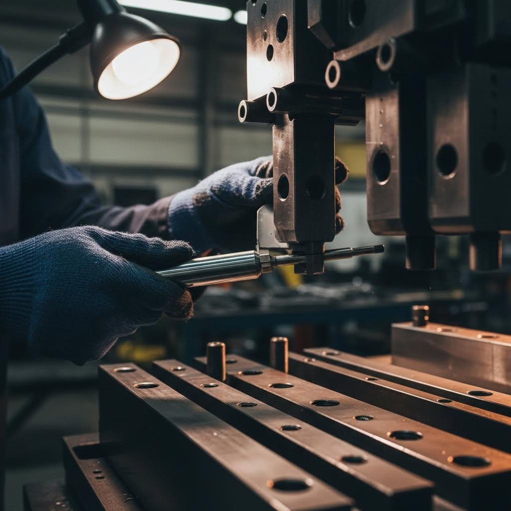
अपने डाई स्टैम्प को एक परिशुद्धता यंत्र के रूप में सोचें जिसकी नियमित देखभाल की आवश्यकता होती है। किसी चीज़ के टूटने तक प्रतीक्षा करना अर्थात् महंगे उत्पादन विघटन और आसपास के घटकों पर त्वरित क्षरण को स्वीकार करना है। एक संरचित रखरोट कार्यक्रम संभावित समस्याओं को महत्वपूर्ण उत्पादन चलाने के दौरान नहीं, बल्कि योजनाबद्ध अवकाश के दौरान संबोधित करता है।
प्रभावी धातु स्टैम्पिंग टूलिंग रखरोट इस आवश्यक जाँच सूची का पालन करती है:
- चलाने के बाद सफाई - प्रत्येक उत्पादन चलाने के बाद डाइज़ की व्यापक सफाई करें। शेष धातु के कण और चिकनाई का जलना आदि महत्वपूर्ण सतहों पर क्षरण को त्वरित करने वाले अपघर्षक के रूप में कार्य करते हैं। उद्योग के आँकड़ों के अनुसार, केवल उचित सफाई से अपघर्षक क्षरण में 20% तक की कमी की जा सकती है।
- चिकनाई की पुष्टि - प्रत्येक चलाने से पहले उचित चिकनाई की पुष्टि करें। सही चिकनाई डाई और शीट धातु के बीच एक सुरक्षात्मक फिल्म बनाती है, जो घर्षण को 80% से अधिक कम कर देती है। यह सरल कदम मुख्य रखरोट की आवश्यकता होने से पहले सेवा जीवन को 30-50% तक बढ़ा सकता है।
- दृश्य निरीक्षण प्रोटोकॉल - प्रत्येक रन के बाद प्रमुख घिसावट क्षेत्रों का निरीक्षण करने के लिए ट्रेन ऑपरेटरों को प्रशिक्षित करें। दरार, चिपिंग या गॉलिंग के प्रारंभिक लक्षणों की खोज करें। यह पूर्वव्यापी उपाय विफलताओं के कारण बनने से पहले विकसित हो रही समस्याओं के 75% से अधिक की पहचान सफलतापूर्वक करता है।
- संरेखण जाँच - साप्ताहिक रूप से या प्रत्येक 10,000 साइकिल्स के बाद गाइड पिन और बुशिंग संरेखण की पुष्टि करें। विसंरेखण असमान घिसावट पैटर्न का कारण बनता है, जो तीव्र गति से बढ़ते हैं।
- अंतर मापन - उचित गेज का उपयोग करके मासिक आधार पर पंच-टू-डाई क्लीयरेंस की जाँच करें। घिसे हुए क्लीयरेंस के कारण अत्यधिक बर्रिंग और किनारों का त्वरित क्षरण होता है।
- स्प्रिंग टेंशन परीक्षण - तिमाही आधार पर स्ट्रिपर और प्रेशर पैड स्प्रिंग्स का परीक्षण करें। कमजोर स्प्रिंग्स के कारण भागों का चिपकना और असंगत फॉर्मिंग दबाव उत्पन्न होता है।
- साइकिल गिनती और लॉगिंग - प्रत्येक डाई सेट के लिए उत्पादन साइकिल्स को ट्रैक करें। यह डेटा भविष्यानुमानात्मक रखरखाव को सक्षम करता है — विफलता की प्रतीक्षा किए बिना भागों को उनके अनुमानित जीवनकाल के 80% पर बदलना।
जैसा कि जेवीएम मैन्युफैक्चरिंग बताती है, अच्छी तरह से रखरखाव वाले उपकरणों से अप्रत्याशित खराबियों की संभावना कम हो जाती है और महंगे उत्पादन विराम को रोका जा सकता है। नियोजित डाउनटाइम के दौरान छोटी-छोटी समस्याओं का समाधान करने से आप आपातकालीन स्थितियों में भागदौड़ के बजाय निरंतर कार्यप्रवाह को सुनिश्चित कर सकते हैं।
डाई घटकों को कब तेज करना, मरम्मत करना या प्रतिस्थापित करना है
हर घिसे हुए घटक को तुरंत प्रतिस्थापित करने की आवश्यकता नहीं होती — लेकिन बहुत देर तक प्रतीक्षा करने से छोटे रखरखाव कार्य बड़ी मरम्मत में बदल जाते हैं। निर्णय लेने के महत्वपूर्ण बिंदुओं को समझना आपको डाई के जीवनकाल और रखरखाव बजट दोनों को अनुकूलित करने में सहायता प्रदान करता है।
तेज करने के अंतराल स्टैम्पिंग की जा रही सामग्री, उत्पादन मात्रा और अवलोकित किनारे की स्थिति पर निर्भर करते हैं। सामान्य दिशानिर्देशों के अनुसार:
- मृदु इस्पात स्टैम्पिंग: प्रत्येक ५०,०००–१,००,००० हिट्स के बाद तेज करें
- स्टेनलेस स्टील या उच्च-शक्ति वाली सामग्रियाँ: प्रत्येक २०,०००–४०,००० हिट्स के बाद तेज करें
- जब बर्र की ऊँचाई सामग्री की मोटाई के १०% से अधिक हो जाए
- जब भी दृश्य निरीक्षण से किनारे पर चिपिंग या गोलाकार होने का पता चले
दो घंटे में एक सामान्य धार निर्माण कार्य को पूरा करने से बाद में 16 घंटे के ठहराव को रोका जा सकता है। घर्षण और धार निर्माण प्रक्रियाएँ मूल ज्यामिति और धार को पुनर्स्थापित करती हैं, जिससे आपके भागों की आवश्यक सहिष्णुताएँ और सतह के फ़िनिश बने रहते हैं।
मरम्मत की आवश्यकता हो जाती है जब घटकों में ऐसा क्षरण दिखाई देता है जिसे धार निर्माण के द्वारा दूर नहीं किया जा सकता, लेकिन वे संरचनात्मक रूप से सुदृढ़ बने हुए होते हैं। गाइड बुशिंग्स, स्ट्रिपर स्प्रिंग्स और स्थान निर्धारण पिन्स अक्सर इस श्रेणी में आते हैं। इन क्षरण वाले घटकों को विफलता की प्रतीक्षा करने के बजाय निर्धारित समय पर प्रतिस्थापित कर देना चाहिए — उत्पादन में अवरोध की लागत प्रतिस्थापन भागों की तुलना में कहीं अधिक होती है।
घटक प्रतिस्थापन का समय जब आप साइकिल गिनती को ट्रैक करते हैं, तो यह एक भविष्यवाणी योग्य पैटर्न का अनुसरण करता है। डाई निर्माण ऑपरेशन्स को डेटा-आधारित प्रतिस्थापन शेड्यूल से लाभ होता है, जिसमें घटकों को उनके अपेक्षित जीवनकाल के 80% पर बदल दिया जाता है। इस दृष्टिकोण से मनमाने प्रतिस्थापन अंतरालों की तुलना में घटकों की लागत 8–12% तक कम हो जाती है, जबकि अप्रत्याशित विफलताओं को लगभग पूरी तरह से समाप्त कर दिया जाता है।
आपके निवेश की रक्षा के लिए भंडारण आवश्यकताएँ
डाई स्टैम्प्स को निष्क्रिय अवस्था में भी खतरों का सामना करना पड़ता है। आर्द्रता सटीक सतहों पर जंग और गड़हे (पिटिंग) का कारण बनती है — यह क्षति सुधारने में महंगी पड़ती है और अक्सर पूरी तरह से उलटी नहीं की जा सकती है। उत्पादन चक्रों के बीच अपने टूलिंग निवेश की रक्षा के लिए उचित भंडारण आवश्यक है।
आवश्यक भंडारण प्रथाएँ इनमें शामिल हैं:
- जलवायु नियंत्रण - उपकरणों को 50% से कम आर्द्रता वाले शुष्क वातावरण में भंडारित करें। यह एकमात्र सावधानी जंग लगने की दर को 99% तक कम कर देती है।
- अंतरासव ढाल - भंडारण से पहले सभी उजागर डाई स्टील सतहों पर संरक्षक तेल या वाष्प जंगरोधी (वैपर कॉरोजन इनहिबिटर्स) लगाएँ।
- उचित सहारा - डाई सेट्स को ऐसे रैक्स पर भंडारित करें जो वार्पिंग (विकृति) या संरेखण विशेषताओं को क्षतिग्रस्त होने से रोकते हों।
- पहचान और दस्तावेज़ीकरण - प्रत्येक डाई को स्पष्ट रूप से लेबल करें तथा रखरखाव के इतिहास, चक्र गिनती और ज्ञात समस्याओं के बारे में सुलभ रिकॉर्ड बनाए रखें।
रखरखाव के अभ्यासों और उत्पादन गुणवत्ता के बीच का संबंध समय के साथ स्पष्ट हो जाता है। वे दुकानें जो व्यवस्थित देखभाल में निवेश करती हैं, वे लगातार विनिर्देश के भीतर भागों का उत्पादन करती हैं, जबकि आपातकालीन मरम्मत और प्रतिस्थापन टूलिंग पर कम खर्च करती हैं। जो दुकानें रखरखाव को स्थगित करती हैं, उन्हें गुणवत्ता संबंधी समस्याओं में वृद्धि, अप्रत्याशित अवरोध समय और निराश ग्राहकों का सामना करना पड़ता है।
लगातार स्टैम्पिंग टूलिंग रखरखाव एक लागत नहीं है—यह एक प्रदर्शन बीमा है जो आपके पूंजी निवेश की रक्षा करता है और उस गुणवत्ता की गारंटी देता है जिसकी आपके ग्राहकों को अपेक्षा होती है। एक बार रखरखाव के अभ्यास स्थापित हो जाने के बाद, अगला विचार डाई निवेश की पूर्ण अर्थव्यवस्था को समझना और टूलिंग के संपूर्ण जीवनकाल में प्रति भाग वास्तविक लागत की गणना करना होता है।
डाई निवेश के लिए लागत विचार और रिटर्न ऑन इन्वेस्टमेंट (आरओआई)
आपने अपने टूलिंग को पूर्णतः बनाए रखा है — लेकिन आपको कैसे पता चलेगा कि यह डाई निवेश शुरुआत में ही वित्तीय रूप से समझदारी भरा था? कई निर्माता प्रारंभिक उद्धरणों पर ध्यान केंद्रित करते हैं, जबकि लाभप्रदता निर्धारित करने वाली वास्तविक अर्थव्यवस्था को अनदेखा कर देते हैं। डाई स्टैम्पिंग लागतों को समझने के लिए खरीद मूल्य के अतिरिक्त, पूरे उत्पादन जीवनकाल के दौरान कुल परियोजना अर्थव्यवस्था का मूल्यांकन करना आवश्यक है।
जीलिक्स के व्यापक लागत विश्लेषण के अनुसार, एक मोल्ड की खरीद मूल्य को उसकी कुल लागत के बराबर मानना निर्माण में सबसे आम फंदों में से एक है। प्रारंभिक मूल्य अक्सर केवल आइसबर्ग की नोक को दर्शाता है — जिसके नीचे विशाल, परियोजना-निर्धारित लागतें छिपी होती हैं।
स्टैम्पिंग डाई निवेश लागतों को चालित करने वाले प्रमुख कारक
स्पष्ट रूप से समान डाइज़ के लिए उद्धरण आपूर्तिकर्ताओं के बीच 50% या अधिक क्यों भिन्न होते हैं? जैसा कि निर्माता स्पष्ट करता है, इस भिन्नता को चालित करने वाले कई कारक हैं — और उन्हें समझना आपको एक निष्क्रिय मूल्य-ग्राहक से एक रणनीतिक निर्णय-लेने वाले व्यक्ति में परिवर्तित कर देता है।
कस्टम धातु स्टैम्पिंग डाई के प्राथमिक लागत ड्राइवर्स में शामिल हैं:
- भाग की ज्यामिति और जटिलता - डाई के अंदर के इंजीनियरिंग में, जटिलता और लागत दुर्लभता से रैखिक संबंध का पालन नहीं करते हैं। बल्कि, यह संबंध अक्सर घातीय होता है। छोटे से छोटे डिज़ाइन विवरण भी उत्पादन लागत पर महत्वपूर्ण प्रभाव डाल सकते हैं।
- सामग्री चयन - टाइटेनियम, एल्यूमीनियम या उच्च-शक्ति वाले इस्पात जैसी विशेषता वाली सामग्रियों से बने भागों के लिए उच्च गुणवत्ता वाले टूल स्टील और कार्बाइड की आवश्यकता होती है, जिससे टूलिंग लागत में काफी वृद्धि हो जाती है।
- सहिष्णुता आवश्यकताएँ - कड़े टॉलरेंस के लिए अधिक सटीक मशीनिंग, बेहतर सामग्रियाँ और अतिरिक्त गुणवत्ता सत्यापन चरणों की आवश्यकता होती है—जो सभी अंतिम मूल्य में योगदान देते हैं।
- अपेक्षित उत्पादन आयतन - उच्च मात्रा में उत्पादन के लिए बहु-कैविटी डिज़ाइन और प्रीमियम सामग्रियों में निवेश का औचित्य निर्धारित किया जा सकता है, जो समय के साथ प्रति भाग लागत को कम करते हैं।
- विक्रेता की क्षमताएँ और स्थान - डाईमेकर्स, डिज़ाइनर्स और इंजीनियर्स के लिए श्रम दरें भौगोलिक क्षेत्र के अनुसार काफी भिन्न होती हैं। कैलिफोर्निया में निर्मित एक टूल की लागत आमतौर पर विस्कॉन्सिन में निर्मित टूल की तुलना में अधिक होती है, क्योंकि जीवन यापन की लागत में अंतर होता है।
आपके भाग को बनाने के लिए उपयोग की जाने वाली प्रक्रिया शायद मॉल्ड लागत में सबसे बड़ा कारक है। एक स्टैम्पिंग डाई निर्माता 5-इंच पिच के साथ 10-स्टेशन प्रोग्रेसिव डाई का अनुमान लगा सकता है, जबकि दूसरा 5.250-इंच पिच के साथ 15-स्टेशन डाई का अनुमान लगाता है। इस प्रसंस्करण विधि के अंतर के कारण महत्वपूर्ण लागत भिन्नताएँ उत्पन्न होती हैं — फिर भी दोनों स्वीकार्य भाग उत्पन्न कर सकते हैं।
डाई के सम्पूर्ण जीवनकाल के दौरान प्रति भाग वास्तविक लागत की गणना
स्मार्ट खरीद पेशेवर समझते हैं कि प्रारंभिक निर्माण लागत अक्सर पहले कुछ वर्षों के दौरान कुल स्वामित्व लागत का केवल 70–80% होती है। अनुसार ग्लेनकॉयन के आरओआई मार्गदर्शिका , "समग्र" लागत की गणना करने के लिए आयुष्य चक्र के खर्चों को ध्यान में रखना आवश्यक है, जिन्हें सामान्यतः प्रारंभिक अनुमानों में शामिल नहीं किया जाता है।
ये छुपी हुई लागत कई श्रेणियों में आती हैं:
| लागत श्रेणी | विवरण | बजट प्रभाव |
|---|---|---|
| डिज़ाइन संशोधन | टी1 नमूना सुधार और इंजीनियरिंग परिवर्तन | प्रारंभिक अनुमान का 10–15% |
| अनुसूचित रखरखाव | शार्पनिंग, घटक प्रतिस्थापन, निवारक रखरखाव | वार्षिक 5-10% |
| अनियोजित मरम्मतें | अप्रत्याशित विफलताओं के लिए आपातकालीन सुधार | परिवर्तनशील लेकिन महत्वपूर्ण |
| पुनरावृत्ति चक्र | उत्पादन की मंजूरी से पहले कई प्रयोग चक्र | प्रत्येक चक्र के लिए प्रेस समय के सप्ताह |
एक व्यावहारिक नियम: पहले 24 महीनों के दौरान जीवनचक्र लागतों को शामिल करने के लिए प्रारंभिक अनुमानों के ऊपर 15-25% का आपातकालीन बजट आवंटित करें। 80,000 डॉलर के कस्टम धातु स्टैम्पिंग डाई के लिए, इसका अर्थ है कि संशोधनों और रखरखाव के लिए अतिरिक्त 12,000–20,000 डॉलर का आवंटन करना।
प्रति भाग वास्तविक लागत की गणना करने के लिए, कुल डाई निवेश (आपातकालीन बजट सहित) को अपेक्षित जीवनकाल उत्पादन मात्रा से विभाजित करें। एक 1 लाख डॉलर का डाई जो 10 लाख भागों का उत्पादन करता है, केवल टूलिंग के अवमूल्यन के लिए प्रति भाग 0.10 डॉलर की लागत लगाता है। वही निवेश जो केवल 1 लाख भागों का उत्पादन करता है, प्रति भाग 1.00 डॉलर पर पहुँच जाता है — अर्थात् अर्थव्यवस्था में दस गुना की वृद्धि।
निर्माता चयन के लिए व्यावसायिक तर्क
यहाँ धातु स्टैम्पिंग डाई निर्माता वास्तव में अपने आप को अलग करते हैं। सबसे सस्ता अनुमान अक्सर तब सबसे महंगा परियोजना बन जाता है जब पुनरावृत्ति चक्र बढ़ जाते हैं और मंजूरी के समय सीमा लंबी हो जाती है।
प्रथम-पास मंजूरी दरों के साथ क्या होता है, इस पर विचार करें। यदि कोई आपूर्तिकर्ता प्रारंभिक नमूनों पर केवल 60% मंजूरी प्राप्त करता है, तो आपको कई सुधार चक्रों का सामना करना पड़ेगा—प्रत्येक चक्र कैलेंडर समय के सप्ताहों का उपभोग करता है और संशोधन लागत के रूप में हज़ारों रुपये खर्च करता है। इसकी तुलना अनुभवी स्टैम्पिंग डाई निर्माताओं के साथ कार्य करने से करें, जो प्रारंभिक प्रस्तुतियों पर 90% से अधिक मंजूरी दर प्राप्त करते हैं।
त्वरित प्रोटोटाइपिंग क्षमताएँ परियोजना के समय-सीमा को और अधिक संकुचित करती हैं। पारंपरिक स्टैम्पिंग डाई निर्माण में प्रारंभिक नमूनों के लिए 8–12 सप्ताह का समय लग सकता है। ऐसे निर्माता जैसे शाओयी केवल 5 दिनों में त्वरित प्रोटोटाइपिंग प्रदान करते हैं, जिससे आपका बाज़ार में पहुँचने का समय काफी तेज़ हो जाता है और विकास लागत में कमी आती है। उनकी 93% प्रथम-पास मंजूरी दर के साथ संयोजित होने पर, यह इंजीनियरिंग विशेषज्ञता सीधे तौर पर परियोजना बचत में अनुवादित होती है।
आपूर्तिकर्ताओं का मूल्यांकन करते समय, इन मूल्य-सृजन करने वाली क्षमताओं का आकलन करें:
- इंजीनियरिंग विशेषज्ञता - अनुभवी टीमें डिज़ाइन के दौरान लागत-बचत के अवसरों की पहचान करती हैं, जिन्हें कम क्षमता वाले आपूर्तिकर्ता पूरी तरह से याद कर देते हैं
- सिमुलेशन क्षमताएँ - उन्नत CAE विश्लेषण लागत-घटित शारीरिक पुनरावृत्ति चक्रों को रोकता है
- प्रथम प्रयास में मंजूरी की दर - उच्च दरें अर्थात् कम सुधार और त्वरित उत्पादन प्रारंभ
- प्रोटोटाइपिंग गति - त्वरित नमूना डिलीवरी विकास के समय-सीमा को संकुचित करती है
- गुणवत्ता सर्टिफिकेशन - IATF 16949 और समान मानक ऐसी मजबूत प्रक्रियाओं को दर्शाते हैं जो निरंतर परिणाम प्रदान करती हैं
सबसे कम उद्धृत मूल्य दुर्लभतः सबसे कम कुल लागत प्रदान करता है। रणनीतिक डाई निवेश का अर्थ है उन भागीदारों का चयन करना जिनकी क्षमताएँ पुनरावृत्ति चक्रों को कम करती हैं, समय-सीमा को त्वरित करती हैं और पहली बार में सही टूलिंग प्रदान करती हैं। यह दृष्टिकोण लागत-गुणवत्ता संतुलन को अनुकूलित करता है जो वास्तविक परियोजना लाभप्रदता का निर्धारण करता है — और आपके संचालन को ऑटोमोटिव और उच्च-परिशुद्धता अनुप्रयोगों में हमारे अगले विषय में विस्तार से चर्चित मांगपूर्ण गुणवत्ता आवश्यकताओं के लिए तैयार करता है।
ऑटोमोटिव और उच्च-परिशुद्धता स्टैम्पिंग डाई अनुप्रयोग
आपने डाई की अर्थव्यवस्था और रखरखाव पर कब्जा कर लिया है — लेकिन जब आपका ग्राहक लाखों भागों में शून्य दोष की मांग करता है, तो क्या होता है? ऑटोमोटिव अनुप्रयोग शीट धातु स्टैम्पिंग प्रौद्योगिकी के लिए अंतिम परीक्षण क्षेत्र का प्रतिनिधित्व करते हैं। इस मांग करने वाले वातावरण में, एक भी दोषपूर्ण घटक सैकड़ों करोड़ डॉलर की लागत वाले रिकॉल को ट्रिगर कर सकता है। यह समझना कि ऑटोमोटिव स्टैम्पिंग डाई सामान्य औद्योगिक टूलिंग से कैसे भिन्न होती है, आपको उद्योग की सबसे कठोर गुणवत्ता आवश्यकताओं के लिए तैयार करता है।
केनमोड के ऑटोमोटिव गुणवत्ता विश्लेषण के अनुसार, आपूर्तिकर्ताओं को शून्य दोष वाले धातु स्टैम्पिंग भागों की आपूर्ति करनी आवश्यक है, जबकि वे लगातार बदलते हुए अंतर्राष्ट्रीय उद्योग मानकों का पालन करते हैं। दांव और भी अधिक ऊँचा है — और आवश्यक गुणवत्ता प्रणालियाँ इसी वास्तविकता को प्रतिबिंबित करती हैं।
डाई निर्माण में ऑटोमोटिव OEM मानकों की पूर्ति करना
ऑटोमोटिव स्टैम्पिंग डाई की आवश्यकताओं को सामान्य धातु स्टैम्पिंग अनुप्रयोगों से क्या अलग करता है? इसका उत्तर एक व्यवस्थित गुणवत्ता प्रबंधन में निहित है, जो डिज़ाइन, उत्पादन और सत्यापन के प्रत्येक पहलू को स्पर्श करता है।
ऑटोमोटिव OEM अपने धातु भागों के स्टैम्पिंग आपूर्तिकर्ताओं से ऑटोमोटिव इंडस्ट्री एक्शन ग्रुप (AIAG) द्वारा विकसित ऑटोमोटिव गुणवत्ता कोर टूल्स को लागू करने की आवश्यकता रखते हैं। AIAG के अनुसार, "ऑटोमोटिव गुणवत्ता कोर टूल्स एक प्रभावी गुणवत्ता प्रबंधन प्रणाली के आधारभूत घटक हैं। आज, अधिकांश ऑटोमोटिव निर्माता और आपूर्तिकर्ता एक या अधिक कोर टूल्स के उपयोग की आवश्यकता रखते हैं।"
ये अनिवार्य ढांचे इन्हें शामिल करते हैं:
- उन्नत उत्पाद गुणवत्ता योजना (APQP) - उत्पादन शुरू होने से पहले डिज़ाइन की दृढ़ता, परीक्षण प्रोटोकॉल, निरीक्षण मानकों और पैकेजिंग आवश्यकताओं सहित 20 से अधिक क्षेत्रों की एक संरचित प्रक्रिया की निगरानी। APQP के माध्यम से निर्माता और उनके स्टैम्पिंग आपूर्तिकर्ता शुरुआती विकास से लेकर उत्पाद लॉन्च तक प्रत्येक चरण पर सहयोग करते हैं।
- उत्पादन भाग स्वीकृति प्रक्रिया (पीपीएपी) - सामान्य भाग योग्यता प्रक्रिया, जो यह सुनिश्चित करती है कि ग्राहक की सभी आवश्यकताओं को समझा गया हो और उत्पादन प्रक्रिया लगातार अनुरूप भागों का उत्पादन कर सके। PPAP गुणवत्ता सत्यापन के लिए महत्वपूर्ण प्रारंभिक कदम का प्रतिनिधित्व करता है।
- विफलता मोड और प्रभाव विश्लेषण (FMEA) - डिज़ाइन, निर्माण और असेंबली में संभावित विफलताओं की प्रणालीगत पहचान। प्रक्रिया FMEA विशेष रूप से धातु स्टैम्पिंग संचालन के दौरान क्या गलत हो सकता है, इसका मूल्यांकन करता है और विफलता की संभावना को कम करने के तरीकों की पहचान करता है।
- माप प्रणाली विश्लेषण (एमएसए) - माप त्रुटि के प्रबंधन और निर्माण प्रक्रियाओं तथा परिणामी उत्पादों में गुणवत्ता सुनिश्चित करने के लिए मानकीकृत प्रक्रियाएँ। इसमें बायस, स्थिरता, रैखिकता और गेज दोहराव और पुनरुत्पादनीयता (GR&R) शामिल हैं।
- सांख्यिकीय प्रक्रिया नियंत्रण (SPC) - नियंत्रण आरेखों का उपयोग करके प्रक्रिया परिवर्तनशीलता के विश्लेषण और वास्तविक समय में निर्माण की निगरानी के लिए वास्तविक समय निगरानी। विनिर्देशों से विचलन तुरंत जांच और सुधारात्मक कार्रवाई को ट्रिगर करते हैं।
जैसा कि डाई-मैटिक के गुणवत्ता प्रबंधन मार्गदर्शिका में जोर दिया गया है, इन प्रणालियों को लागू करने के लिए "प्रक्रिया के प्रत्येक चरण और प्रत्येक कार्यदिवस के प्रत्येक मिनट में विस्तार से ध्यान देने" की आवश्यकता होती है। गुणवत्ता को स्रोत स्तर पर बढ़ावा देने पर जोर ऑपरेटरों को संभावित समस्याओं को पहली रक्षा रेखा के रूप में पकड़ने और उनका समाधान करने की क्षमता प्रदान करता है।
प्रेसिजन स्टैम्पिंग के लिए महत्वपूर्ण गुणवत्ता प्रमाणपत्र
ऑटोमोटिव स्टैम्पिंग डाई की खरीद करते समय, प्रमाणन स्थिति आपूर्तिकर्ता की क्षमता के बारे में त्वरित अंतर्दृष्टि प्रदान करती है। IATF 16949 मानक एक ऐसा मानक है जिसे गंभीर ऑटोमोटिव आपूर्तिकर्ताओं को पूरा करना आवश्यक है।
IATF 16949 प्रमाणन से यह संकेत मिलता है कि आपूर्तिकर्ता ने निम्नलिखित क्षमताओं का प्रदर्शन किया है:
- जटिल गुणवत्ता प्रबंधन प्रणाली - ऑटोमोटिव संबंधित उत्पादों के डिज़ाइन, उत्पादन, स्थापना और सेवा को शामिल करने वाली दस्तावेज़ीकृत प्रक्रियाएँ
- निरंतर सुधार की संस्कृति - दोषों के निवारण और विचरण तथा अपव्यय के कमी के लिए व्यवस्थित दृष्टिकोण
- पूर्ण प्रशिक्षणीयता - उत्पादन के दौरान प्रत्येक घटक, सामग्री बैच और प्रक्रिया पैरामीटर को ट्रैक करने की क्षमता
- ग्राहक-विशिष्ट आवश्यकताएं - आधारभूत मानकों के अतिरिक्त व्यक्तिगत OEM विनिर्देशों का एकीकरण
- सप्लाई चेन प्रबंधन - गुणवत्ता आवश्यकताओं को उप-स्तर के आपूर्तिकर्ताओं तक विस्तारित करने वाले नियंत्रण
प्रमाणन के अतिरिक्त, ऑटोमोटिव OEM अक्सर आयामी सहिष्णुता, सतह परिष्करण आवश्यकताएँ, सामग्री परीक्षण प्रोटोकॉल और प्रलेखन मानकों सहित अतिरिक्त विनिर्देशों को लागू करते हैं। ये ग्राहक-विशिष्ट आवश्यकताएँ IATF 16949 की आधारभूत अपेक्षाओं से काफी अधिक हो सकती हैं।
ऑटोमोटिव अनुप्रयोगों में पहचान योग्यता (ट्रेसेबिलिटी) की आवश्यकताओं पर विशेष ध्यान देने की आवश्यकता होती है। प्रत्येक भाग को विशिष्ट सामग्री बैचों, उत्पादन तिथियों, मशीन सेटिंग्स और ऑपरेटर पहचानों तक पहचान योग्य होना चाहिए। जब भी कोई समस्या उत्पन्न होती है—यहाँ तक कि उत्पादन के वर्षों बाद भी—यह पहचान योग्यता त्वरित मूल कारण विश्लेषण और लक्षित नियंत्रण उपायों की अनुमति प्रदान करती है।
IATF 16949 प्रमाणित निर्माताओं जैसे के साथ कार्य करना शाओयी गुणवत्ता आश्वासन प्रदान करता है जिसकी ऑटोमोटिव OEM को आवश्यकता होती है। उनकी उन्नत CAE सिमुलेशन क्षमताएँ भौतिक टूलिंग काटने से पहले दोष-मुक्त परिणामों की गारंटी देती हैं, जबकि उनकी इंजीनियरिंग टीम का OEM-मानक टूलिंग के साथ उच्च-मात्रा विनिर्माण में विशेषज्ञता मांग करने वाले अनुप्रयोगों के लिए उद्योग-नेतृत्व वाली क्षमता का प्रतिनिधित्व करती है।
ऑटोमोटिव डाईज़ में परिशुद्धता और गुणवत्ता नियंत्रण में क्या अंतर है
ऑटोमोटिव स्टैम्पिंग डाईज़ को सामान्य औद्योगिक टूलिंग द्वारा दुर्लभ रूप से सामना किए जाने वाले मांगों का सामना करना पड़ता है। कड़ी सहिष्णुताओं, उच्च उत्पादन मात्राओं और शून्य-दोष की अपेक्षाओं का संयोजन अद्वितीय इंजीनियरिंग चुनौतियाँ पैदा करता है।
मुख्य भिन्नताएँ शामिल हैं:
- तंग आयामी सहिष्णुता - ऑटोमोटिव घटकों के लिए अक्सर ±0.05 मिमी या उससे भी कड़ी सहिष्णुताओं की आवश्यकता होती है, जबकि सामान्य औद्योगिक अनुप्रयोगों में सामान्यतः ±0.1 मिमी होती है
- सतह फिनिश की आवश्यकताएं - दृश्यमान बाहरी पैनलों के लिए नियंत्रित प्रकाश स्थितियों के तहत किसी भी पता लगाए जा सकने वाले दोष के बिना क्लास A सतह गुणवत्ता की आवश्यकता होती है
- उच्च उत्पादन मात्राएँ - ऑटोमोटिव स्टैम्पिंग डाई के जीवन की अपेक्षा अक्सर 1 मिलियन साइकिल से अधिक होती है, जिसके लिए प्रीमियम सामग्री और मजबूत निर्माण की आवश्यकता होती है
- सामग्री की जटिलता - उन्नत उच्च-सामर्थ्य इस्पात और एल्यूमीनियम मिश्र धातुओं के बढ़ते उपयोग की मांग विशेषज्ञता वाले टूलिंग ज्ञान को आवश्यक बनाती है
- प्रक्रिया के दौरान सत्यापन - दृश्य निरीक्षण, डाई के अंदर सेंसर और स्वचालित मापन सहित वास्तविक समय निगरानी प्रणालियाँ उत्पादन चक्र के दौरान संगत गुणवत्ता सुनिश्चित करती हैं
गुणवत्ता-उन्मुख धातु स्टैम्पर्स टॉनेज मॉनिटरिंग, गलत फीडिंग और स्लग धारण के लिए डाई के अंदर सेंसर लगाते हैं। दृश्य प्रणालियाँ भाग की उपस्थिति और अभिविन्यास की पुष्टि करती हैं। लेज़र मापन उत्पादन को रोए बिना महत्वपूर्ण आयामों की पुष्टि करता है। ये स्टैम्पिंग प्रौद्योगिकी निवेश वास्तविक समय गुणवत्ता सत्यापन को सक्षम बनाते हैं, जो ऑटोमोटिव अनुप्रयोगों द्वारा आवश्यकता होती है।
निर्माण के लिए डिज़ाइन (DFM) सहयोग विकास प्रक्रिया के आरंभ में ही किया जाना चाहिए, ताकि ऑटोमोटिव स्टैम्पिंग डाई शुरुआत से ही अनुकूलित की जा सकें। गुणवत्ता विशेषज्ञों के अनुसार, हालाँकि कोई घटक स्टैम्पिंग समग्र उत्पाद डिज़ाइन में छोटा प्रतीत हो सकता है, फिर भी यह विश्वसनीयता, लागत और उत्पादन दक्षता में महत्वपूर्ण अंतर ला सकता है। प्रारंभिक इंजीनियरिंग संलग्नता विफलता के जोखिम को कम करती है, जबकि लागत को नियंत्रित रखती है — यही वह बात है जो ऑटोमोटिव OEM अपने आपूर्ति आधार से अपेक्षित करते हैं।
शीट धातु स्टैम्पिंग डाई के बारे में अक्सर पूछे जाने वाले प्रश्न
1. धातु स्टैम्पिंग डाई की कीमत कितनी होती है?
धातु स्टैम्पिंग डाई की लागत सरल टूलिंग के लिए $500 से $15,000 तक होती है, जबकि जटिल ऑटोमोटिव डाई की लागत $100,000 से अधिक हो सकती है। प्रमुख लागत निर्धारक कारकों में भाग की ज्यामितीय जटिलता, सामग्री का चयन, सहिष्णुता आवश्यकताएँ और अपेक्षित उत्पादन मात्रा शामिल हैं। डिज़ाइन संशोधनों, निर्धारित रखरखाव और पुनरावृत्ति चक्रों के लिए अतिरिक्त 15–25% आपातकालीन बजट का प्रावधान करना न भूलें। प्रति-भाग लागत उच्च मात्रा के साथ काफी कम हो जाती है — एक $100,000 की डाई जो 1 मिलियन भागों का उत्पादन करती है, उसकी टूलिंग की कुल लागत का प्रति भाग अंशन केवल $0.10 होता है।
2. शीट मेटल स्टैम्पिंग डाइज़ क्या हैं?
शीट मेटल स्टैम्पिंग डाइज़ कठोर उपकरण इस्पात से निर्मित परिशुद्धता वाले उपकरण हैं, जो समतल धातु की चादरों को काटते, आकार देते और विशिष्ट त्रि-आयामी भागों में रूपांतरित करते हैं। ये डाइज़ एक जोड़े के रूप में कार्य करते हैं—ऊपरी और निचले घटक—जो स्टैम्पिंग प्रेस द्वारा लगाए गए विशाल बल के तहत एक साथ आते हैं। ये डाइज़ चार आवश्यक कार्य करते हैं: सामग्री की स्थिति निर्धारित करना, उसे स्थिर रखने के लिए क्लैम्प करना, काटना और मोड़ना जैसे कार्यों को करना, तथा पूर्ण भाग को जारी करना। एक बार उचित रूप से निर्मित हो जाने के बाद, डाइज़ प्रति मिनट 1,000 से अधिक स्ट्रोक की गति से समान भागों का उत्पादन कर सकते हैं।
3. डाइ कट और स्टैम्पिंग में क्या अंतर है?
डाई कटिंग और स्टैम्पिंग धातु निर्माण की अलग-अलग प्रक्रियाएँ हैं। डाई कास्टिंग में सिरों या बिलेट्स का उपयोग किया जाता है, जिन्हें उनके गलनांक से अधिक गर्म किया जाता है, जबकि स्टैम्पिंग में शीट धातु के ब्लैंक्स या कॉइल्स का उपयोग ठंडी कार्य प्रक्रिया में किया जाता है। स्टैम्पिंग डाइज़ यांत्रिक रूप से कम्पनित दबाव के माध्यम से कमरे के तापमान पर सामग्री को काटते, मोड़ते और आकार देते हैं। स्टैम्पिंग प्रक्रिया उच्च मात्रा उत्पादन के लिए त्वरित साइकिल समय प्रदान करती है और शीट धातु की मोटाई की विस्तृत श्रृंखला के साथ काम करती है, जिससे यह ऑटोमोटिव घटकों, ब्रैकेट्स और सटीक भागों के लिए आदर्श हो जाती है।
4. स्टैम्पिंग डाइज़ के मुख्य प्रकार कौन-कौन से हैं और मुझे प्रत्येक का उपयोग कब करना चाहिए?
चार प्रमुख प्रकार हैं: प्रगतिशील डाई, ट्रांसफर डाई, संयुक्त डाई, और संयोजन डाई। प्रगतिशील डाई मध्यम जटिलता के भागों के उच्च-मात्रा उत्पादन में उत्कृष्टता प्रदर्शित करती हैं, जिनमें कार्य-टुकड़ों को एक पट्टी से बांधकर कई स्टेशनों के माध्यम से ले जाया जाता है। ट्रांसफर डाई जटिल डिज़ाइनों और गहरी ड्रॉ को संभालती हैं, जिसमें भागों को प्रारंभ में ही अलग कर दिया जाता है और फिर उन्हें यांत्रिक रूप से स्थानांतरित किया जाता है। संयुक्त डाई सभी कार्यों को एकल स्ट्रोक में करती हैं, जो वॉशर जैसे सरल समतल भागों के लिए आदर्श हैं। भाग की जटिलता, उत्पादन मात्रा और बजट प्रतिबंधों के आधार पर चयन करें।
5. मैं अपनी स्टैम्पिंग डाई के जीवनकाल को कैसे बढ़ा सकता हूँ?
व्यवस्थित निवारक रखरखाव को लागू करें, जिसमें चलाने के बाद सफाई, स्नेहन सत्यापन और नियमित दृश्य निरीक्षण शामिल हों। मृदु इस्पात के लिए प्रत्येक 50,000–100,000 आघातों के बाद और उच्च-शक्ति वाली सामग्रियों के लिए प्रत्येक 20,000–40,000 आघातों के बाद कटिंग धारों को तेज करें। गाइड पिन संरेखण की साप्ताहिक जाँच करें और पंच-टू-डाई के मार्जिन को मासिक रूप से मापें। डाई को 50% आर्द्रता से कम के जलवायु-नियंत्रित वातावरण में संग्रहित करें तथा उन पर संक्षारण-रोधी लेप लगाएँ। इस दृष्टिकोण से अप्रत्याशित अवरोध को 70% से अधिक कम किया जा सकता है तथा आपातकालीन प्रतिक्रियात्मक मरम्मत की तुलना में लागत 12–18% कम आती है।