 छोटे पर्चे, उच्च मानदंड। हमारी तेजी से प्रोटोटाइपिंग सेवा मान्यता को तेजी से और आसानी से बनाती है —

कस्टम धातु प्रोटोटाइपिंग के रहस्य: आपकी परियोजना को नष्ट कर रही लागत-वृद्धि वाली गलतियाँ
कस्टम धातु प्रोटोटाइपिंग को समझना और उसकी उत्पाद विकास में भूमिका
क्या आपने कभी सोचा है कि इंजीनियर डिजिटल डिज़ाइन को उत्पादन में लाखों रुपये के निवेश करने से पहले एक वास्तविक, कार्यात्मक धातु भाग में कैसे परिवर्तित करते हैं? यहीं पर कस्टम धातु प्रोटोटाइपिंग का योगदान होता है। यह अवधारणा और वास्तविकता के बीच एक महत्वपूर्ण सेतु है, जो आपके उत्पाद विकास के समय-सीमा को सफल या विफल बना सकता है।
कस्टम धातु प्रोटोटाइपिंग एक या कुछ सीमित संख्या में धातु भागों का निर्माण करने की प्रक्रिया है, जिसका उद्देश्य पूर्ण-पैमाने पर उत्पादन से पहले डिज़ाइन की वैधता की जाँच करना होता है; इससे टीमें रूप, फिट और कार्यक्षमता का परीक्षण कर सकती हैं, जबकि जोखिम और निवेश को न्यूनतम किया जा सकता है।
मानक विनिर्माण के विपरीत, जो उच्च मात्रा वाले उत्पादन चक्र पर केंद्रित होता है, यह दृष्टिकोण मात्रा की तुलना में डिज़ाइन सत्यापन को प्राथमिकता देता है। आप हज़ारों समान भाग नहीं बना रहे हैं। इसके बजाय, आप अपने डिज़ाइन के सटीक भौतिक प्रतिनिधित्व बना रहे हैं, ताकि एक मूलभूत प्रश्न का उत्तर दिया जा सके: क्या यह वास्तव में काम करेगा?
धातु प्रोटोटाइपिंग को कस्टम क्यों कहा जाता है
यहाँ शब्द "कस्टम" केवल विपणन का एक शब्द नहीं है। यह निर्माताओं द्वारा प्रोटोटाइप निर्माण के प्रति दृष्टिकोण में एक मौलिक परिवर्तन का प्रतिनिधित्व करता है। जब आप एक कस्टम धातु प्रोटोटाइप ऑर्डर करते हैं , तो प्रत्येक विशिष्टता आपकी सटीक आवश्यकताओं के अनुसार अनुकूलित की जाती है। इसमें अद्वितीय ज्यामितियाँ, विशिष्ट सामग्री का चयन और सटीक सहिष्णुताएँ शामिल हैं, जिन्हें सामान्य ऑफ-द-शेल्फ घटक बिल्कुल भी पूरा नहीं कर सकते।
इसे इस तरह से सोचें। मानक विनिर्माण स्थापित टेम्पलेट्स और प्रमाणित डिज़ाइनों पर कार्य करता है। धातु प्रोटोटाइप विनिर्माण, इसके विपरीत, आपकी CAD फ़ाइलों और इंजीनियरिंग आवश्यकताओं के साथ नए सिरे से शुरू होता है। यह प्रक्रिया निम्नलिखित को समायोजित करती है:
- जटिल ज्यामितियाँ जो कैटलॉग से प्राप्त करना असंभव है
- उत्पादन के उद्देश्य के अनुरूप विशिष्ट मिश्र धातु संरचनाएँ
- कार्यात्मक परीक्षण के लिए आवश्यक कड़ी सहिष्णुताएँ
- अंतिम उत्पादन गुणवत्ता को प्रतिबिंबित करने वाले सतह परिष्करण
इस स्तर की अनुकूलन क्षमता इंजीनियरों को ऐसे प्रोटोटाइप का मूल्यांकन करने की अनुमति देती है जो वास्तव में उत्पादन वातावरण द्वारा उत्पादित किए जाने वाले परिणाम का प्रतिनिधित्व करते हैं। प्रोटोलैब्स के अनुसार, जब प्रोटोटाइप उत्पादन विधियों के साथ सटीक रूप से मेल खाते हैं, तो डिज़ाइनर डिज़ाइन सत्यापन और प्रदर्शन परीक्षण के दौरान अधिक आत्मविश्वास प्राप्त करते हैं।
अवधारणा से भौतिक सत्यापन तक
इंजीनियर, उत्पाद विकासकर्ता और निर्माता धातु प्रोटोटाइपिंग को अटल मान क्यों मानते हैं? क्योंकि डिजिटल सिमुलेशन, चाहे वे कितने भी उन्नत क्यों न हों, वास्तविक दुनिया के प्रदर्शन को पूरी तरह से पुनरुत्पादित नहीं कर सकते हैं। एक प्रोटोटाइप सेवा प्रदाता इस अंतर को पाटता है जो आपको छूने योग्य, तनाव-परीक्षण योग्य और संयोजनों में एकीकृत करने योग्य भौतिक भाग प्रदान करता है।
धातु प्रोटोटाइप बनाने का मूल उद्देश्य तीन सत्यापन स्तंभों पर केंद्रित है:
- फॉर्म: क्या भौतिक ज्यामिति डिज़ाइन के उद्देश्य के अनुरूप है? क्या यह बड़े संयोजन (एसेंबली) के भीतर फिट होगा?
- फिट: यह मिलान घटकों के साथ कैसे प्रतिक्रिया करता है? क्या सहनशीलता (टॉलरेंस) उपयुक्त है?
- कार्यः क्या यह वास्तविक परिचालन स्थितियों के तहत अपना कार्य करता है?
यह प्रारंभिक मूल्य प्रमाण बुद्धिमान निर्णय और संशोधनों को सक्षम बनाता है, जिससे जोखिम कम होते हैं और अंतिम उत्पाद को आदर्श बनाया जा सकता है। जैसा कि ज़िन्टिलॉन ने उल्लेख किया है, प्रोटोटाइप चरण के दौरान मुद्दों का पता लगाना एक नवाचार संस्कृति को समर्थन देता है, जहाँ विफलता एक सीखने का अवसर बन जाती है, न कि उत्पादन की एक आपदा।
उच्च परिशुद्धता घटकों की आवश्यकता वाले उद्योगों ने धातु प्रोटोटाइप निर्माण को अपने विकास चक्रों के लिए आवश्यक मान लिया है। एयरोस्पेस कंपनियाँ इसका उपयोग उड़ान परीक्षण से पहले हल्की संरचनाओं के मान्यन के लिए करती हैं। चिकित्सा उपकरण निर्माता इस पर जैव-संगतता और आयामी शुद्धता सुनिश्चित करने के लिए निर्भर करते हैं। स्वचालित इंजीनियर नियामक प्रमाणन से पहले चेसिस घटकों के तनाव परीक्षण के लिए इस पर निर्भर करते हैं।
बढ़ता हुआ महत्व एक सरल तथ्य से उत्पन्न होता है: डिज़ाइन की कमी को खोजने की लागत विकास के प्रत्येक चरण में कई गुना बढ़ जाती है। प्रोटोटाइपिंग के दौरान कोई समस्या खोजना आपके लिए कुछ दिनों और कुछ सैकड़ों डॉलर की लागत ला सकता है। लेकिन उसी समस्या का पता उत्पादन के दौरान लगना? यह याददाश्त में वापसी, पुनः उपकरण स्थापना और क्षतिग्रस्त प्रतिष्ठा के कारण लाखों डॉलर का कारण बन सकता है।
धातु प्रोटोटाइप बनाने के पाँच मुख्य तरीके
तो आपने निर्णय ले लिया है कि आपकी परियोजना को एक भौतिक धातु प्रोटोटाइप की आवश्यकता है। अब अगला महत्वपूर्ण प्रश्न आता है: आप किस निर्माण विधि का चयन करें? इसका उत्तर आपकी ज्यामिति, सामग्री आवश्यकताओं, बजट और समयसीमा पर निर्भर करता है। आइए आज के कस्टम धातु प्रोटोटाइपिंग में प्रमुखता प्राप्त पाँच मुख्य दृष्टिकोणों का विश्लेषण करें।
प्रत्येक विधि विशिष्ट अनुप्रयोगों के लिए विशिष्ट लाभ प्रदान करती है। गलत विधि का चयन करना केवल धन का अपव्यय नहीं करता—यह आपके संपूर्ण विकास कार्यक्रम को सप्ताहों तक विलंबित कर सकता है। इन अंतरों को प्रारंभ में ही समझना, आपको निर्माताओं के साथ प्रभावी ढंग से संवाद करने और महंगे संशोधनों से बचने में सहायता करता है।
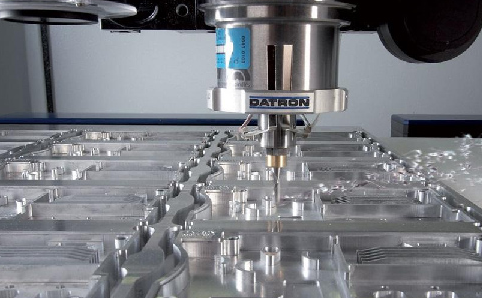
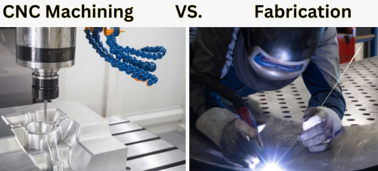
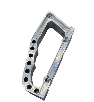
उच्च-सटीकता वाले प्रोटोटाइप के लिए सीएनसी मशीनिंग
जब सटीकता सर्वाधिक महत्वपूर्ण होती है, तो सीएनसी मशीनिंग अभी भी सुनहरा मानक बनी हुई है। यह घटक-हटाने वाली निर्माण प्रक्रिया एक ठोस धातु के ब्लॉक से आरंभ होती है और कंप्यूटर संख्यात्मक नियंत्रण द्वारा निर्देशित घूर्णन काटने वाले औजारों का उपयोग करके सामग्री को हटाती है। इसे माइक्रॉन-स्तर की सटीकता के साथ मूर्तिकारी की तरह सोचें।
इंजीनियर इसकी ओर क्यों आकर्षित होते हैं कार्यात्मक प्रोटोटाइप के लिए सीएनसी प्रक्रिया अत्युत्तम आयामी शुद्धता प्रदान करती है—मानक सहिष्णुता ±0.127 मिमी है, जबकि उन्नत विकल्प ±0.0127 मिमी तक पहुँच सकते हैं। आप उत्पादन-गुणवत्ता वाले ठोस बिलेट्स के साथ काम कर रहे हैं, जिसका अर्थ है कि आपका प्रोटोटाइप अंतिम भाग के समान ही द्रव्यमान गुणों को प्रदर्शित करता है। सही ढंग से प्रोग्राम किया गया एक धातु काटने वाला यंत्र एल्यूमीनियम, स्टेनलेस स्टील, टाइटेनियम, तांबा या पीतल को आपके डिज़ाइन द्वारा आवश्यक लगभग किसी भी ज्यामिति में परिवर्तित कर सकता है।
सीमाएँ क्या हैं? औजार की पहुँच कुछ आंतरिक कोष्ठों और अधोमुखी (अंडरकट) को सीमित करती है। ऐसे जटिल आंतरिक चैनल जिन तक ड्रिल या एंड मिल पहुँच नहीं सकती है, उनके लिए वैकल्पिक विधियों की आवश्यकता होती है। इसके अतिरिक्त, यह घटात्मक प्रक्रिया होने के कारण द्रव्यमान अपव्यय भी होता है—उस बिलेट से जो कुछ भी हटाया जाता है, वह सभी दुकान के फर्श पर चिप्स के रूप में समाप्त हो जाता है।
जब शीट मेटल फॉर्मिंग उचित होती है
क्या आपको एनक्लोज़र, ब्रैकेट, फ्रेम या चैसिस घटकों की आवश्यकता है? शीट मेटल प्रोटोटाइपिंग सीधे काटने, मोड़ने और असेंबली के माध्यम से समतल धातु की चादरों को कार्यात्मक भागों में परिवर्तित करती है। यह विधि पतली-दीवार वाले संरचनात्मक घटकों को तेज़ी से और लागत-प्रभावी तरीके से निर्मित करने में उत्कृष्ट प्रदर्शन करती है।
इस प्रक्रिया की शुरुआत आमतौर पर लेज़र कटिंग या वॉटरजेट कटिंग के माध्यम से सटीक समतल पैटर्न बनाने से होती है। लेज़र कटर अत्युत्तम किनारा गुणवत्ता प्रदान करता है और जटिल प्रोफाइल को आसानी से संभाल सकता है। इसके बाद, सीएनसी प्रेस ब्रेक निर्दिष्ट मोड़ रेखाओं के अनुदिश सामग्री को मोड़ता है। वेल्डिंग या हार्डवेयर स्थापना असेंबली को पूरा करती है।
तीव्र शीट मेटल निर्माण उन परियोजनाओं के लिए उत्कृष्ट है जिनमें ठोस स्टॉक से मशीनिंग की लागत के बिना उत्पादन-गुणवत्ता की शक्ति की आवश्यकता होती है। सहिष्णुता आमतौर पर ±0.38 से ±0.76 मिमी के मध्य होती है—सीएनसी मशीनिंग की तुलना में कम सटीक, लेकिन संरचनात्मक अनुप्रयोगों के लिए पूर्णतः स्वीकार्य। समझौता क्या है? आपकी सीमा अपेक्षाकृत एकसमान दीवार मोटाई और सरल ज्यामितीय जटिलता वाले भागों तक ही सीमित है।
शीट मेटल प्रोटोटाइपिंग उत्पादन के साथ भी सुचारू रूप से जुड़ जाती है। आपके प्रोटोटाइप के लिए उपयोग की जाने वाली समान प्रक्रियाओं को उच्च मात्रा में सीधे स्केल किया जा सकता है, जिससे यह बड़े पैमाने पर उत्पादन में स्टैम्पिंग या फॉर्मिंग के लिए डिज़ाइन किए गए उत्पादों के मान्यन के लिए आदर्श बन जाती है।
एडिटिव मैन्युफैक्चरिंग और मेटल 3D प्रिंटिंग
जब आपकी डिज़ाइन में आंतरिक चैनल, लैटिस संरचनाएँ, या ऐसी ज्यामितियाँ होती हैं जिन तक कोई पारंपरिक उपकरण नहीं पहुँच सकता, तो क्या होता है? यहाँ मेटल 3D प्रिंटिंग का प्रवेश होता है। सिलेक्टिव लेज़र मेल्टिंग (SLM) और डायरेक्ट मेटल लेज़र सिंटरिंग (DMLS) जैसी तकनीकें धातु चूर्ण को सटीक लेज़रों के साथ संगलित करके घटकों को परत-दर-परत निर्मित करती हैं।
यह एडिटिव दृष्टिकोण पूर्ण डिज़ाइन स्वतंत्रता प्रदान करता है। तापीय प्रबंधन के लिए आंतरिक शीतलन चैनल? संभव है। टॉपोलॉजी विश्लेषण के माध्यम से अनुकूलित कार्बनिक आकृतियाँ? कोई समस्या नहीं। आंतरिक लैटिस के माध्यम से भार कम करना? मानक प्रथा है। एडिटिव निर्माण के माध्यम से धातु त्वरित प्रोटोटाइपिंग ऐसी ज्यामितियों को सक्षम करती है जिनके लिए पारंपरिक विधियों का उपयोग करते समय कई मशीन किए गए घटकों और जटिल असेंबलियों की आवश्यकता होती है।
यह तकनीक एल्यूमीनियम, टाइटेनियम, स्टेनलेस स्टील, इनकोनेल और विशिष्ट मिश्र धातुओं के साथ काम करती है। हालाँकि, छापे गए रूप में रफ सतह समाप्ति की अपेक्षा करें, जिसके लिए पोस्ट-प्रोसेसिंग की आवश्यकता होती है। लागत अन्य विधियों की तुलना में अधिक है, क्योंकि महंगे धातु पाउडर और मशीन रनटाइम के कारण। सरल ज्यामितियों के लिए, सीएनसी मशीनिंग आमतौर पर अधिक आर्थिक रूप से फायदेमंद सिद्ध होती है।
सामग्री-विशिष्ट आवश्यकताओं के लिए ढलाई
निवेश ढलाई—जिसे खोई हुई मोम ढलाई भी कहा जाता है—द्रवित धातु को सिरेमिक छाँचों में डालकर प्रोटोटाइप बनाती है, जिनमें उत्पादन-उद्देश्य के धातुकर्मीय गुण होते हैं। आधुनिक दृष्टिकोणों में 3D-मुद्रित मोम या राल के पैटर्न का उपयोग किया जाता है, जिससे प्रोटोटाइप मात्रा के लिए महंगे स्थायी औजारों की आवश्यकता समाप्त हो जाती है।
यह विधि बड़े, भारी या मोटी दीवार वाले घटकों के लिए उत्कृष्ट है, जहाँ यांत्रिक काटने से अत्यधिक सामग्री का अपव्यय होगा। यह विशिष्ट दाने की संरचना और ऐसे धातु गुण प्रदान करती है जिन्हें योगात्मक निर्माण (एडिटिव मैन्युफैक्चरिंग) द्वारा पुनरुत्पादित नहीं किया जा सकता है। इसका समझौता लंबे नेतृत्व समय (2–6 सप्ताह) और कम सटीक टॉलरेंस के साथ होता है, जिसके कारण महत्वपूर्ण आयामों के लिए द्वितीयक यांत्रिक काटने की आवश्यकता होती है।
संरचनात्मक असेंबलियों के लिए वेल्डिंग निर्माण
कुछ प्रोटोटाइप एकल भाग नहीं होते—वे एक साथ जुड़े कई घटकों की आवश्यकता वाले संयोजन होते हैं। वेल्डिंग निर्माण कटिंग, फॉर्मिंग और जॉइनिंग प्रक्रियाओं को एकीकृत करता है ताकि विभिन्न धातु खंडों से संरचनात्मक असेंबलियाँ बनाई जा सकें।
यह दृष्टिकोण उन फ्रेम्स, समर्थन संरचनाओं और प्रोटोटाइप्स के लिए उपयुक्त है जिन्हें अंततः समान जोड़ने की विधियों के माध्यम से उत्पादित किया जाएगा। डाई कट मशीन या लेजर कटिंग के माध्यम से व्यक्तिगत घटकों का निर्माण किया जाता है, जिन्हें फिर कुशल वेल्डर आपके विनिर्देशों के अनुसार असेंबल करते हैं। यह विधि एकल असेंबली के भीतर विभिन्न सामग्री मोटाई और मिश्र धातुओं को संयोजित करने में लचीलापन प्रदान करती है।
एक नज़र में विधि तुलना
सही दृष्टिकोण का चयन करने के लिए कई कारकों का एक साथ मूल्यांकन करना आवश्यक है। निम्नलिखित तुलना प्रत्येक विधि के अनुकूल परिणाम प्रदान करने के समय को स्पष्ट करने में सहायता करती है:
| विधि | सर्वश्रेष्ठ उपयोग | सामान्य सहनशीलता | सामग्री के विकल्प | सापेक्ष लागत |
|---|---|---|---|---|
| सीएनसी मशीनिंग | उच्च-परिशुद्धता कार्यात्मक भाग, कड़ी सहिष्णुता वाले घटक | ±0.127 मिमी मानक; ±0.0127 मिमी उन्नत | एल्यूमीनियम, स्टेनलेस स्टील, टाइटेनियम, तांबा, पीतल, कांस्य | मध्यम से उच्च |
| शीट मेटल फॉर्मिंग | एन्क्लोज़र्स, ब्रैकेट्स, फ्रेम्स, चेसिस घटक | ±0.38–0.76 मिमी | एल्यूमीनियम, स्टील, तांबा, पीतल, टाइटेनियम, मैग्नीशियम | निम्न से मध्यम |
| मेटल 3D प्रिंटिंग | जटिल ज्यामितियाँ, आंतरिक चैनल, हल्के वजन वाले लैटिस | ±0.2 मिमी (L<100मिमी); ±0.2% × L (L>100मिमी) | एल्यूमीनियम, टाइटेनियम, स्टेनलेस स्टील, इनकोनेल, मैरेजिंग स्टील | उच्च |
| निवेश मोल्डिंग | बड़े घटक, उत्पादन-उद्देश्य धातुविज्ञान, पुल उत्पादन | ±0.05–0.25 मिमी | एल्यूमीनियम, कार्बन स्टील, स्टेनलेस स्टील, निकेल मिश्र धातुएँ, तांबा मिश्र धातुएँ | मध्यम |
| वेल्डिंग फ़ाब्रिकेशन | संरचनात्मक असेंबलियाँ, फ्रेम, बहु-घटक प्रोटोटाइप | ±0.5–1.5 मिमी (आमतौर पर) | इस्पात, एल्युमीनियम, स्टेनलेस स्टील | निम्न से मध्यम |
विधि चयन को मार्गदर्शन देने वाले निर्णय कारक
आप अपनी परियोजना की आवश्यकताओं को सही प्रोटोटाइपिंग विधि में कैसे अनुवादित करते हैं? इन तीन प्राथमिक कारकों पर विचार करें:
- ज्यामिति जटिलता: आंतरिक विशेषताएँ, अंडरकट और कार्गिक आकृतियाँ धातु 3D मुद्रण की ओर प्रेरित करती हैं। सरल प्रिज्मैटिक भाग CNC मशीनिंग को प्राथमिकता देते हैं। पतली-दीवार वाले आवरण शीट धातु प्रोटोटाइप दृष्टिकोण के साथ संरेखित होते हैं।
- सामग्री के आवश्यकताएँ: क्या आपको विशिष्ट धातुविज्ञान गुणों या दाने की संरचनाओं की आवश्यकता है? ढलाई इसे प्रदान करती है। क्या आपको उत्पादन-समान सामग्री व्यवहार की आवश्यकता है? ठोस बिलेट से CNC मशीनिंग उत्पादन उद्देश्य के अनुरूप है। क्या आप विशेष मिश्र धातुओं के साथ काम कर रहे हैं जो केवल पाउडर के रूप में उपलब्ध हैं? ऐडिटिव निर्माण आवश्यक हो जाता है।
- मात्रा और बजट: एकल जटिल भाग अक्सर 3D मुद्रण लागत को औचित्यपूर्ण ठहराते हैं। कई समान शीट धातु प्रोटोटाइप लेज़र कटिंग और फॉर्मिंग की दक्षता से लाभान्वित होते हैं। ब्रिज उत्पादन चक्र दोहराए जा सकने वाले पैटर्न के साथ ढलाई की ओर झुके होते हैं।
यूनियनफैब के अनुसार, किसी विधि का चयन करते समय हमेशा डिज़ाइन जटिलता, सामग्री आवश्यकताएँ, परिशुद्धता, लागत और उत्पादन मात्रा का मूल्यांकन करें—प्रत्येक प्रक्रिया में समझौते शामिल होते हैं जो आपके विशिष्ट प्रोटोटाइप लक्ष्यों के साथ संरेखित होने चाहिए।
इन पाँच मुख्य विधियों को समझना आपको निर्माताओं के साथ संलग्न होने पर सूचित निर्णय लेने में सक्षम बनाता है। लेकिन सही प्रक्रिया का चयन समीकरण का केवल एक हिस्सा है—आप जो सामग्री निर्दिष्ट करते हैं, वह प्रोटोटाइप सफलता के लिए समान रूप से महत्वपूर्ण भूमिका निभाती है।
धातु प्रोटोटाइप परियोजनाओं के लिए सामग्री चयन मार्गदर्शिका
आपने अपनी निर्माण विधि का चयन कर लिया है। अब एक ऐसा निर्णय लेने का समय आ गया है जो बाद की सभी प्रक्रियाओं को प्रभावित करेगा: आपका प्रोटोटाइप किस धातु का उपयोग करेगा? गलत सामग्री का चयन न केवल आपके वर्तमान प्रोटोटाइप को प्रभावित करता है—बल्कि यह उत्पादन योजना को भी बाधित कर सकता है, लागत को बढ़ा सकता है और कार्यात्मक परीक्षण की गुणवत्ता को समाप्त कर सकता है।
कस्टम धातु प्रोटोटाइपिंग के लिए सामग्री का चयन एक साथ कई कारकों के संतुलन की आवश्यकता रखता है। यांत्रिक कार्यक्षमता (मशीनेबिलिटी) निर्माण की गति और लागत निर्धारित करती है। यांत्रिक गुण कार्यात्मक प्रदर्शन को निर्धारित करते हैं। वेल्डेबिलिटी असेंबली के विकल्पों को प्रभावित करती है। और उत्पादन संगतता सुनिश्चित करती है कि आपका प्रोटोटाइप वास्तव में उसी का सटीक प्रतिनिधित्व करे जो अंततः विनिर्माण द्वारा वितरित किया जाएगा।
एल्यूमीनियम मिश्र धातुएँ और उनके प्रोटोटाइपिंग लाभ
जब इंजीनियरों को उत्कृष्ट यांत्रिक कार्यक्षमता वाले हल्के प्रोटोटाइप की आवश्यकता होती है, तो एल्यूमीनियम शीट धातु सूची में सबसे ऊपर होती है। जैसा कि मशीनिंग डॉक्टर कहते हैं, एल्यूमीनियम सबसे आसान सामग्री समूह में से एक है जिसे मशीन किया जा सकता है, जिसकी मशीनेबिलिटी रेटिंग स्टील के आधार रेटिंग की तुलना में 350% तक पहुँच सकती है।
यह आपके प्रोटोटाइप बजट के लिए इसलिए महत्वपूर्ण क्यों है? उच्च मशीनीकरण क्षमता सीधे तौर पर त्वरित साइकिल समय, लंबे उपकरण जीवन और कम निर्माण लागत की ओर जाती है। आपका प्रोटोटाइप जल्दी पहुँचता है और कम लागत पर तैयार होता है।
प्रोटोटाइपिंग के लिए सबसे आम एल्यूमीनियम मिश्र धातुएँ इनमें से कुछ हैं:
- 6061-T6: एक व्यापक रूप से उपयोग की जाने वाली मिश्र धातु जो उत्कृष्ट मशीनीकरण क्षमता, अच्छी संक्षारण प्रतिरोधकता और वेल्डेबिलिटी प्रदान करती है। लगभग 40,000 psi की यील्ड सामर्थ्य इसे संरचनात्मक अनुप्रयोगों के लिए उपयुक्त बनाती है। यह बहुमुखी एल्यूमीनियम शीट एन्क्लोज़र्स से लेकर हाइड्रोलिक वाल्व बॉडीज़ तक सभी को संभाल सकती है।
- 7075-T6: 6061 की तुलना में लगभग दोगुनी शक्ति, लेकिन लगभग तीन गुना अधिक लागत पर। विमानन उद्योग इस मिश्र धातु को पंख के स्पार्स और उच्च-तनाव घटकों के लिए पसंद करता है। मशीनीकरण क्षमता का मान लगभग 170% के आसपास होने की अपेक्षा करें—जो अभी भी उत्कृष्ट है, हालाँकि यह उपकरणों पर अधिक क्षरणकारी होती है।
- 2024-T3: तांबे-मिश्रित एल्यूमीनियम, जो विमानन अनुप्रयोगों में आम है। यांत्रिक गुण मृदु इस्पात के समीप होते हैं, हालाँकि 6000-श्रेणी की मिश्र धातुओं की तुलना में संक्षारण प्रतिरोधकता कम हो जाती है।
शीट मेटल प्रोटोटाइप के लिए, 5052 मिश्र धातु की एल्यूमीनियम शीट मोड़ के दौरान दरार के बिना उत्कृष्ट आकार देने की क्षमता प्रदान करती है। अधिकांश प्रोटोटाइप अनुप्रयोगों के लिए मोटाई के विकल्प आमतौर पर 20 गेज (0.032 इंच) से 10 गेज (0.102 इंच) तक होते हैं।
प्रोटोटाइप भागों के लिए स्टेनलेस स्टील का चयन
क्या आपको संक्षारण प्रतिरोध, शक्ति और तापमान सहनशीलता की आवश्यकता है? स्टेनलेस स्टील शीट ये तीनों गुण प्रदान करती है। क्रोमियम की मात्रा—कम से कम 10.5%—एक सुरक्षात्मक ऑक्साइड परत बनाती है जो जंग लगने को रोकती है और रासायनिक आक्रमण के प्रति प्रतिरोधी होती है।
मांग वाले प्रोटोटाइप अनुप्रयोगों के लिए 316 स्टेनलेस स्टील ग्रेड विशेष रूप से उभरता है। RapidDirect के अनुसार, यह मिश्र धातु 2–3% मॉलिब्डेनम युक्त होती है, जो क्लोराइड्स, अम्लों और समुद्री वातावरण के प्रति उत्कृष्ट प्रतिरोध प्रदान करती है। हीट एक्सचेंजर, फार्मास्यूटिकल उपकरण और समुद्री घटकों में अक्सर 316 स्टेनलेस स्टील का उल्लेख किया जाता है।
लेकिन यहाँ चयन अधिक सूक्ष्म हो जाता है। 316 और 316L स्टेनलेस स्टील के बीच का अंतर कार्बन सामग्री पर केंद्रित है:
- 316 स्टेनलेस: अधिकतम 0.08% कार्बन। उच्च कठोरता और तन्य शक्ति सहित बेहतर यांत्रिक गुण।
- 316L स्टेनलेस: अधिकतम 0.03% कार्बन। वेल्डिंग के दौरान कार्बाइड अवक्षेपण के कम होने के कारण उत्कृष्ट वेल्डेबिलिटी। जब आपके प्रोटोटाइप में व्यापक वेल्डिंग की आवश्यकता होती है, तो यह वरीय विकल्प है।
के लिए वेल्डेड असेंबली के लिए निर्धारित प्रोटोटाइप , 316L स्टेनलेस स्टील शीट मेटल वेल्डिंग के बाद मानक 316 में होने वाले अंतराणुक संक्षारण को रोकता है। ग्रेड्स के बीच लागत अंतर न्यूनतम बना रहता है, इसलिए चयन आपकी निर्माण आवश्यकताओं पर केंद्रित होना चाहिए, न कि बजट पर।
304 स्टेनलेस स्टील कम मांग वाले वातावरणों के लिए लागत-प्रभावी विकल्प प्रदान करता है। यह अधिकांश सामान्य उद्देश्यों के अनुप्रयोगों को अच्छी तरह से संभालता है, हालाँकि यह मॉलिब्डेनम की मात्रा के अभाव में 316 की श्रेष्ठ संक्षारण प्रतिरोधक क्षमता को नहीं दर्शाता है।
कार्बन स्टील और लागत-प्रभावी संरचनात्मक विकल्प
जब संरचनात्मक प्रदर्शन और बजट के मुकाबले संक्षारण प्रतिरोध कम महत्वपूर्ण होता है, तो कार्बन स्टील असाधारण मूल्य प्रदान करता है। स्टील प्लेट और कोल्ड-रोल्ड स्टील शीट 316 स्टेनलेस स्टील के समीप की शक्ति प्रदान करते हैं, लेकिन लागत का केवल एक भाग ही होते हैं।
प्रोटोटाइपिंग के लिए सामान्य ग्रेड शामिल हैं:
- 1018 स्टील: कम-कार्बन स्टील, जिसमें उत्कृष्ट वेल्डेबिलिटी और फॉर्मेबिलिटी होती है। इसे आसानी से मशीन किया जा सकता है और कार्बन केस हार्डनिंग के द्वारा घर्षण प्रतिरोध के लिए उपयुक्त बनाया जा सकता है। यह संरचनात्मक घटकों के लिए आदर्श है, जहाँ पेंटिंग या प्लेटिंग द्वारा संक्षारण सुरक्षा प्रदान की जाती है।
- 4140 मिश्र धातु स्टील: क्रोमियम-मॉलिब्डेनम स्टील, जो एयरोस्पेस और उच्च-तनाव अनुप्रयोगों के लिए उपयुक्त है। इसे 50 Rc कठोरता तक ऊष्मा उपचारित किया जा सकता है, जिसकी तन्य शक्ति मृदु स्टील की तुलना में तीन गुना होती है।
जैल्वेनाइज़्ड शीट मेटल कार्बन स्टील की शक्ति के साथ-साथ जस्ते की परत प्रदान करता है, जो संक्षारण सुरक्षा प्रदान करती है। गैल्वेनाइज़inग प्रक्रिया एक विशिष्ट स्पैंगल्ड पैटर्न बनाती है—जो औद्योगिक अनुप्रयोगों के लिए उत्कृष्ट है, लेकिन जहाँ दृश्य आकर्षण महत्वपूर्ण हो, वहाँ कम उपयुक्त है। गैल्वेनील स्टील में एक ऐनीलिंग चरण जोड़ा जाता है, जो पेंट करने की योग्यता में सुधार करता है, जबकि संक्षारण प्रतिरोध बना रहता है।
कार्बन स्टील की धातु की प्लेट भारी संरचनात्मक प्रोटोटाइप के लिए उपयुक्त है, जहाँ ठोस स्टॉक से मशीनिंग, शीट से निर्माण की तुलना में अधिक आर्थिक रूप से फायदेमंद सिद्ध होती है। मोटाई के विकल्प शीट मेटल के मानक गेज से काफी अधिक विस्तारित होते हैं और प्लेट की मोटाई इंच के भिन्नात्मक माप में व्यक्त की जाती है।
अनुप्रयोग आवश्यकताओं के अनुरूप सामग्री गुणों का मिलान करना
प्रमुख मिश्र धातु परिवारों के अतिरिक्त, विशिष्ट अनुप्रयोगों के लिए विशिष्ट सामग्रियों की आवश्यकता होती है। पीतल और कांस्य तापीय, विद्युतीय या सौंदर्य-संबंधी गुणों के महत्वपूर्ण होने पर विशिष्ट प्रोटोटाइपिंग आवश्यकताओं को पूरा करते हैं।
क्या आप अपने अनुप्रयोग के लिए पीतल और कांस्य में से कौन-सा चुनें — इस बारे में सोच रहे हैं? यह अंतर महत्वपूर्ण है:
- पीतल (C260): तांबा-जिंक मिश्र धातु जो अत्युत्तम मशीनिंग योग्यता, संक्षारण प्रतिरोध और आकर्षक सुनहरे रंग की उपस्थिति प्रदान करती है। यह सजावटी हार्डवेयर, समुद्री फिटिंग्स और विद्युत घटकों के लिए आदर्श है। प्रोटोलैब्स के अनुसार, पीतल को वैकल्पिक कूलेंट के साथ आसानी से मशीन किया जा सकता है, जिसमें उत्कृष्ट टूल जीवन और उच्च फीड रेट्स होते हैं।
- ब्रोंज़: तांबा-टिन मिश्र धातु जिसमें उत्कृष्ट घर्षण प्रतिरोधकता और कम घर्षण होता है। ब्रॉन्ज़ के स्व-स्नेहन गुणों से बेयरिंग सतहें, बुशिंग्स और सरकने वाले घटकों को लाभ होता है।
चरम परिस्थितियों के लिए, विशेष मिश्र धातुएँ प्रयोग में लाई जाती हैं। इनकॉनेल 2,000°F से अधिक तापमान को संभाल सकता है—जो गैस टरबाइन और जेट इंजन प्रोटोटाइप के लिए आवश्यक है। टाइटेनियम इस्पात के आधे वजन पर एयरोस्पेस-ग्रेड ताकत प्रदान करता है, और चिकित्सा प्रत्यारोपणों के लिए उत्कृष्ट जैव-संगतता रखता है।
सामग्री चयन संदर्भ सारणी
निम्नलिखित तुलना सामान्य प्रोटोटाइपिंग सामग्रियों के लिए प्रमुख चयन मानदंडों को संक्षेप में प्रस्तुत करती है:
| सामग्री श्रेणी | सामान्य ग्रेड | मशीनीकरण रेटिंग | वेल्डिंग की क्षमता | आदर्श प्रोटोटाइप अनुप्रयोग |
|---|---|---|---|---|
| एल्यूमीनियम मिश्र धातु | 6061-T6, 7075-T6, 2024-T3 | 170%–270% | अच्छा (6061); सीमित (7075) | एयरोस्पेस संरचनाएँ, आवरण, हल्के घटक |
| स्टेनलेस स्टील | 304, 316, 316L, 17-4 PH | 45%–60% | अच्छा (316L); मध्यम (316) | चिकित्सा उपकरण, समुद्री घटक, खाद्य उपकरण |
| कार्बन स्टील | 1018, 4140, A36 | 70%–80% | उत्कृष्ट | संरचनात्मक फ्रेम, फिक्सचर, लागत-संवेदनशील भाग |
| पीतल | C260, C360 | 100%–300% | अच्छा (ब्रेज़ करने योग्य) | सजावटी हार्डवेयर, विद्युत, समुद्री फिटिंग्स |
| तांबा | C932, C954 | 80%–100% | अच्छा (ब्रेज़ करने योग्य) | बेयरिंग, बुशिंग, क्षरण प्रतिरोधी घटक |
| टाइटेनियम | Ti-6Al-4V (ग्रेड 5) | 25%–35% | निष्क्रिय वातावरण की आवश्यकता होती है | एयरोस्पेस, मेडिकल इम्प्लांट्स, उच्च-प्रदर्शन भाग |
मोटाई विचार और गेज संदर्भ
सामग्री की मोटाई सीधे निर्माण विधि के चयन और कार्यात्मक प्रदर्शन दोनों को प्रभावित करती है। शीट धातु प्रोटोटाइप आमतौर पर गेज माप का उपयोग करते हैं, जबकि प्लेट स्टॉक दशमलव इंच या मिलीमीटर को संदर्भित करता है।
आम प्रोटोटाइप मोटाइयाँ इनमें से कुछ हैं:
- 20 गेज (0.036" स्टील / 0.032" एल्युमीनियम): हल्के आवरण, सजावटी पैनल
- 16 गेज (0.060" स्टील / 0.051" एल्युमीनियम): मानक ब्रैकेट, चेसिस घटक
- 14 गेज (0.075" स्टील): संरचनात्मक ब्रैकेट, भारी फ्रेम
- 11 गेज (0.120" स्टील): भारी ड्यूटी संरचनात्मक अनुप्रयोग
याद रखें कि गेज संख्याएँ विपरीत दिशा में काम करती हैं—कम संख्या अधिक मोटाई को दर्शाती है। यह अक्सर दशमलव माप के आदी इंजीनियरों को भ्रमित कर देता है। इसके अतिरिक्त, स्टील और एल्युमीनियम के बीच गेज-से-मोटाई रूपांतरण अलग-अलग होते हैं, अतः सदैव अपने फैब्रिकेटर के साथ वास्तविक आयामों की पुष्टि करें।
आपका सामग्री चयन प्रोटोटाइपिंग सफलता की नींव तैयार करता है। लेकिन यहाँ तक कि सही सामग्री का चयन भी प्रक्रिया के क्रियान्वयन में विफलताओं की भरपाई नहीं कर सकता। CAD तैयारी से लेकर अंतिम निरीक्षण तक पूर्ण प्रोटोटाइपिंग कार्यप्रवाह को समझना आपको उन जालों से बचने में सहायता करता है जो परियोजनाओं को देरी कर देते हैं और लागत को बढ़ा देते हैं।
पूर्ण कस्टम धातु प्रोटोटाइपिंग प्रक्रिया की व्याख्या
आपने अपनी सामग्री और निर्माण विधि का चयन कर लिया है। अब क्या? CAD मॉडल से तैयार धातु प्रोटोटाइप तक की यात्रा में कई चरण शामिल हैं—जिनमें से प्रत्येक चरण को यदि सही ढंग से संभाला नहीं गया, तो देरी, लागत अतिव्यय और गुणवत्ता में विफलता के अवसर उत्पन्न हो सकते हैं।
इस पूर्ण कार्यप्रवाह को समझना आपको एक निष्क्रिय ग्राहक से एक सूचित साझेदार में बदल देता है, जो समस्याओं की पूर्वानुमान लगा सकता है, सही इनपुट प्रदान कर सकता है और अपनी परियोजना को समय पर रख सकता है। आइए प्रारंभिक डिज़ाइन से अंतिम निरीक्षण तक प्रत्येक चरण के माध्यम से चलें।
- डिज़ाइन तैयारी और CAD फ़ाइल निर्माण
- निर्माण के लिए डिज़ाइन (DFM) समीक्षा
- सामग्री और विधि चयन की पुष्टि
- उद्धरण और नेतृत्व समय अनुमान
- निर्माण कार्यान्वयन
- परिष्करण संचालन
- गुणवत्ता निरीक्षण और मान्यीकरण
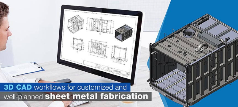
प्रोटोटाइपिंग सफलता के लिए अपनी CAD फ़ाइलों की तैयारी
आपका प्रोटोटाइप उतना ही अच्छा है जितना कि आपके द्वारा प्रदान की गई फ़ाइल है। CNC मशीनें, लेज़र कटर और प्रेस ब्रेक मिलीमीटर के अंशों तक निर्देशों का पालन करते हैं। यदि आपका CAD डेटा अपूर्ण है, गलत ढंग से स्वरूपित है, या इसमें समस्याग्रस्त ज्यामिति शामिल है, तो आप अधिकतम स्थिति में देरी की उम्मीद कर सकते हैं—और खराब हुए भागों की सबसे खराब स्थिति में।
धातु निर्माण के लिए कौन-से फ़ाइल प्रारूप काम करते हैं? इसका उत्तर आपकी प्रोटोटाइपिंग विधि पर निर्भर करता है:
- STEP (.stp, .step): 3D ठोस मॉडल के लिए सार्वभौमिक मानक। JLCCNC के अनुसार, STEP फ़ाइलें विभिन्न CAD प्लेटफ़ॉर्मों के बीच चिकनी वक्रों, सटीक आयामों और पूर्ण 3D ज्यामिति को संरक्षित करती हैं। यह प्रारूप CNC मशीनिंग, ढलाई के लिए पैटर्न और धातु 3D प्रिंटिंग के लिए उपयुक्त है।
- IGES (.igs, .iges): एक पुराना मानक जो अभी भी व्यापक रूप से स्वीकार किया जाता है। IGES सतह की ज्यामिति को अच्छी तरह संभालता है, लेकिन जटिल ठोस विशेषताओं के साथ संघर्ष कर सकता है। जब STEP उपलब्ध न हो, तो इसका उपयोग करें।
- DXF (.dxf): शीट मेटल प्रोटोटाइप निर्माण के लिए सबसे उपयुक्त प्रारूप। DXF फ़ाइलें 2D समतल पैटर्न को समाहित करती हैं, जो लेज़र कटिंग और वॉटरजेट संचालन को नियंत्रित करती हैं। आपका निर्माता आपके 3D डिज़ाइन को इन 2D प्रोफ़ाइल्स में विस्तारित करता है।
- पैरासॉलिड (.x_t, .x_b): Solid Edge और SolidWorks के लिए विशिष्ट, यह प्रारूप जटिल CNC कार्य के लिए उच्च ज्यामितीय सटीकता को संरक्षित करता है।
धातु निर्माण के लिए STL या OBJ जैसे मेश-आधारित प्रारूपों से बचें। ये प्रारूप प्लास्टिक की 3D प्रिंटिंग के लिए कार्य करते हैं, लेकिन चिकनी वक्रों को छोटे-छोटे त्रिभुजों में तोड़ देते हैं—जो सतह की निरंतरता के महत्वपूर्ण होने वाले सटीक मशीनिंग के लिए समस्याग्रस्त है।
परियोजनाओं को देरी करने वाली सामान्य फ़ाइल तैयारी की गलतियाँ इनमें से कुछ हैं:
- ज्यामिति का अभाव या अपूर्णता (सतहें जो उचित रूप से जुड़ी नहीं हैं)
- गलत मापन (मिलीमीटर मॉडल को इंच के रूप में या इसके विपरीत जमा करना)
- यांत्रिक क्षमताओं से अधिक जटिल विशेषताएँ
- वास्तविक ज्यामिति के बजाय एम्बेडेड छवियाँ या पाठ
- एकल ठोस की आवश्यकता होने पर एकाधिक शरीर
फ़ाइल जमा करने से पहले सत्यापित करें कि सभी सतहें बंद हैं, आयाम आपके इरादे के अनुरूप हैं, और महत्वपूर्ण विशेषताएँ स्पष्ट रूप से परिभाषित हैं। फ़ाइल सफ़ाई के कुछ मिनट दिनों भर की पीछे-आगे की स्पष्टीकरण प्रक्रिया से बचाते हैं।
DFM समीक्षा चरण
यहाँ अनुभवी निर्माता अपनी कीमत साबित करते हैं। निर्माण के लिए डिज़ाइन (DFM) समीक्षा मूल्यांकन करती है कि क्या आपका डिज़ाइन वास्तव में कुशलतापूर्ण ढंग से उत्पादित किया जा सकता है—और ऐसे संशोधनों की पहचान करती है जो कार्यक्षमता को बिना समझौता किए लागत को कम करते हैं।
एक व्यापक DFM समीक्षा क्या जाँचती है? के अनुसार एनालॉजी डिज़ाइन एक व्यापक DFM चेकलिस्ट में ज्यामिति सरलीकरण, एकसमान दीवार की मोटाई, ड्राफ्ट कोण, सहिष्णुता नियंत्रण और सुविधा की पहुँच शामिल हैं। विशेष रूप से शीट मेटल निर्माण के लिए, समीक्षा निम्नलिखित बिंदुओं पर ध्यान केंद्रित करती है:
- मोड़ त्रिज्या: आंतरिक बेंड त्रिज्या आमतौर पर सामग्री की मोटाई के बराबर होनी चाहिए। अधिक तंग बेंड्स के कारण दरारें पड़ने का खतरा होता है, विशेष रूप से कठोर मिश्र धातुओं में।
- छेद से किनारे की दूरी: बेंड्स या किनारों के बहुत निकट स्थित सुविधाएँ आकृति देने के दौरान विकृत हो सकती हैं। मानक प्रथा के अनुसार न्यूनतम दूरी सामग्री की मोटाई के 2-3 गुना रखी जाती है।
- न्यूनतम विशेषता आकार: छोटे छेद, संकरे स्लॉट और पतली दीवारों की व्यावहारिक सीमाएँ आपकी सामग्री और उसकी मोटाई के आधार पर निर्धारित होती हैं। एक शीट मेटल गेज चार्ट का संदर्भ लेने से आपका डिज़ाइन निर्माणीय आयामों के साथ संरेखित हो जाता है।
- मोड़ क्रम की संभवता: जटिल भागों के लिए विशिष्ट बेंडिंग क्रम की आवश्यकता हो सकती है। कुछ ज्यामितियाँ उपकरण हस्तक्षेप उत्पन्न कर सकती हैं, जिससे कुछ बेंड अनुक्रम असंभव हो जाते हैं।
सीएनसी मशीन किए गए प्रोटोटाइप के लिए, DFM समीक्षा उपकरण पहुँच, गहरे पॉकेट्स के लिए उचित आयाम अनुपात और चुनी गई सामग्री के आधार पर प्राप्त करने योग्य सहिष्णुताओं पर केंद्रित होती है।
लक्ष्य आपके डिज़ाइन को सीमित करना नहीं है—बल्कि यह पहचानना है कि कहाँ छोटे-मोटे संशोधन लागत को काफी कम कर सकते हैं या विश्वसनीयता में उल्लेखनीय सुधार कर सकते हैं। एक अनावश्यक रूप से कड़ी सहिष्णुता (टॉलरेंस) को हटाने से मशीनिंग समय आधा हो सकता है। बेंड त्रिज्या (बेंड रेडियस) में थोड़ा-सा समायोजन महँगी द्वितीयक कार्यवाही को समाप्त कर सकता है।
सहिष्णुता (टॉलरेंस) संबंधी विचार और महत्वपूर्ण आयामों का संचार
आपके प्रोटोटाइप पर प्रत्येक आयाम को समान ध्यान देने की आवश्यकता नहीं होती है। अति-सहिष्णुता (ओवर-टॉलरेंसिंग)—अर्थात् सभी स्थानों पर कड़ी सहिष्णुता लागू करना—कार्यात्मक लाभ के बिना लागत को बढ़ा देता है। जबकि महत्वपूर्ण विशेषताओं पर अपर्याप्त सहिष्णुता (अंडर-टॉलरेंसिंग) फिटिंग और कार्यक्षमता में विफलता का कारण बन सकती है।
प्रोटोटाइप शीट मेटल भागों के लिए सहिष्णुता (टॉलरेंस) कैसे निर्धारित करें? शुरुआत करें उन आयामों की पहचान से जो वास्तव में महत्वपूर्ण हैं:
- महत्वपूर्ण आयाम: वे विशेषताएँ जो संलग्न घटकों के साथ अंतरफलक (इंटरफ़ेस) करती हैं, कार्यक्षमता निर्धारित करती हैं या असेंबली को प्रभावित करती हैं। इन्हें कड़ी सहिष्णुता और स्पष्ट रूप से उल्लिखित कॉलआउट्स की आवश्यकता होती है।
- गैर-महत्वपूर्ण आयाम: बाकी सभी। मानक शॉप सहिष्णुता लागू करें और धन की बचत करें।
शीट मेटल निर्माण के लिए मानक सहिष्णुताएँ आमतौर पर ±0.38 से ±0.76 मिमी के बीच होती हैं। सीएनसी मशीनिंग ±0.127 मिमी की मानक सहिष्णुता प्राप्त करती है, जबकि महत्वपूर्ण विशेषताओं के लिए अतिरिक्त लागत पर ±0.025 मिमी संभव है। जब केवल दो छिद्रों की ही उस सटीकता की आवश्यकता हो, तो पूरे भाग के लिए ±0.025 मिमी की सहिष्णुता निर्दिष्ट करना बजट का काफी हिस्सा व्यर्थ कर देता है।
अपने ड्रॉइंग्स पर महत्वपूर्ण आयामों को स्पष्ट रूप से संचारित करें। जब स्थिति, समतलता या लंबवतता महत्वपूर्ण हो, तो जीडी&टी (ज्यामितीय आयामन एवं सहिष्णुता) कॉलआउट्स का उपयोग करें। कार्य-के-लिए-महत्वपूर्ण विशेषताओं को हाइलाइट करें। विशिष्ट सहिष्णुताओं की आवश्यकता के कारणों को स्पष्ट करने वाले नोट्स शामिल करें—यह संदर्भ निर्माताओं को आपके विनिर्देशों के कारण उत्पादन चुनौतियों के समय वैकल्पिक समाधान सुझाने में सहायता करता है।
कच्चे सामग्री से तैयार प्रोटोटाइप तक
एक बार जब डीएफएम समीक्षा पूर्ण हो जाती है और आपने कोटेशन को स्वीकार कर लिया है, तो निर्माण प्रक्रिया शुरू हो जाती है। विशिष्ट कार्यप्रवाह आपके चुने गए विधि पर निर्भर करता है, लेकिन धातु निर्माण सामान्यतः इस क्रम का अनुसरण करता है:
- सामग्री खरीद: आपका फैब्रिकेटर आपकी विशिष्टताओं के अनुरूप कच्चा स्टॉक प्राप्त करता है। मानक मिश्र धातुएँ शीघ्र ही भेजी जाती हैं; विशेष प्रकार की सामग्री के लिए नेतृत्व समय की आवश्यकता हो सकती है। उद्धरण प्रस्तुत करते समय सामग्री की उपलब्धता की पुष्टि करने से अप्रत्याशित स्थितियों से बचा जा सकता है।
- प्रोग्रामिंग: सीएएम (CAM) सॉफ़्टवेयर आपके डिज़ाइन को मशीन निर्देशों में बदलता है। सीएनसी (CNC) कार्य के लिए, इसका अर्थ है टूलपाथ (उपकरण-पथ) उत्पन्न करना। शीट मेटल के लिए, इसमें समतल पैटर्न का नेस्टिंग (समूहीकरण) और बेंड (मोड़) अनुक्रम के प्रोग्रामिंग का समावेश होता है।
- प्राथमिक निर्माण: मुख्य आकृति निर्माण क्रिया—मशीनिंग, लेज़र कटिंग, बेंडिंग या एडिटिव बिल्डिंग—भाग की मूल ज्यामिति का निर्माण करती है।
- द्वितीयक कार्य: हार्डवेयर सम्मिलन, टैपिंग, डीबरिंग और असेंबली के चरण फैब्रिकेशन चरण को पूरा करते हैं।
- पूर्णता: पाउडर कोटिंग, एनोडाइज़िंग, प्लेटिंग या पेंटिंग जैसे सतह उपचार आपके प्रोटोटाइप की रक्षा करते हैं और उसके गुणों को बढ़ाते हैं।
- जांच: गुणवत्ता सत्यापन सुनिश्चित करता है कि आपका प्रोटोटाइप शिपिंग से पूर्व विनिर्देशों के अनुरूप है।
निर्माण के पूरे दौरान, प्रमाणन की आवश्यकता वाले उद्योगों के लिए सामग्री की ट्रेसैबिलिटी महत्वपूर्ण होती है। एयरोस्पेस और चिकित्सा प्रोटोटाइप्स के लिए अक्सर मिल प्रमाणपत्रों की आवश्यकता होती है, जो सामग्री की रचना और गुणों के बारे में दस्तावेज़ीकरण प्रदान करते हैं। इन आवश्यकताओं को शुरुआत में ही निर्दिष्ट करें—निर्माण के बाद ट्रेसैबिलिटी को लागू करना कठिन या असंभव साबित हो सकता है।
फिनिशिंग ऑपरेशन और सतह उपचार
कच्चे निर्मित भाग दुर्लभता से अंतिम उत्पाद की दृश्य विशेषता या प्रदर्शन का प्रतिनिधित्व करते हैं। फिनिशिंग ऑपरेशन मशीन किए गए या आकार दिए गए धातु को प्रोटोटाइप शीट धातु भागों में परिवर्तित करते हैं, जो उत्पादन घटकों के समान दिखाई देते हैं और कार्य करते हैं।
सामान्य परिष्करण विकल्पों में शामिल हैं:
- पाउडर कोटिंग: लगभग किसी भी रंग में उपलब्ध टिकाऊ, आकर्षक फिनिश। पेंट किए गए उत्पादन भागों के लिए निर्धारित स्टील और एल्यूमीनियम प्रोटोटाइप्स के लिए उत्कृष्ट।
- एनोडाइज़िंग: एक इलेक्ट्रोकेमिकल प्रक्रिया जो एल्यूमीनियम की प्राकृतिक ऑक्साइड परत को मोटा करती है। प्रकार II एनोडाइजिंग रंगीन फिनिश के लिए डाई को स्वीकार करती है; प्रकार III (हार्डकोट) घर्षण प्रतिरोध में काफी सुधार करती है।
- प्लेटिंग: जिंक, निकल या क्रोम प्लेटिंग संक्षारण सुरक्षा और विशिष्ट सतह गुणों को प्रदान करती है। जिंक प्लेटिंग लागत-प्रभावी सुरक्षा प्रदान करती है; निकल कठोरता और रासायनिक प्रतिरोध प्रदान करता है।
- निष्क्रियता: स्टेनलेस स्टील के लिए रासायनिक उपचार जो मुक्त लोहे को हटाता है और संक्षारण प्रतिरोध को बढ़ाता है। चिकित्सा और खाद्य संपर्क वाले प्रोटोटाइप के लिए आवश्यक।
- बीड ब्लास्टिंग: एक समान मैट टेक्सचर बनाता है जो मशीनिंग के निशानों को छुपाता है और सतह को कोटिंग के लिए तैयार करता है।
फिनिशिंग अतिरिक्त समय लगाती है—आमतौर पर प्रक्रिया की जटिलता और बैच आकार के आधार पर 2–5 दिन। अपने प्रोटोटाइप के समयसूची की योजना बनाते समय इस अवधि के लिए बजट निर्धारित करें।
गुणवत्ता निरीक्षण और मान्यीकरण
अंतिम चरण पुष्टि करता है कि आपका प्रोटोटाइप विनिर्देशों को पूरा करता है। निरीक्षण के क्षेत्र में मूल आयामी सत्यापन से लेकर व्यापक प्रथम-लेख निरीक्षण रिपोर्ट तक की श्रेणी शामिल है।
मानक प्रोटोटाइप निरीक्षण में आमतौर पर निम्नलिखित शामिल होते हैं:
- कैलीपर्स, माइक्रोमीटर या सीएमएम का उपयोग करके महत्वपूर्ण आयामों का सत्यापन
- सतह के दोषों, बर्र्स या फिनिश की गुणवत्ता के लिए दृश्य निरीक्षण
- धागेदार छिद्रों, हार्डवेयर फिटिंग और असेंबली संगतता के लिए कार्यात्मक जाँच
नियमित उद्योगों के लिए, औपचारिक निरीक्षण प्रलेखन की आवश्यकता हो सकती है। प्रथम लेख निरीक्षण (FAI) रिपोर्ट्स प्रत्येक ड्रॉइंग आयाम और विशिष्टता के अनुपालन को दस्तावेज़ित करती हैं। सामग्री प्रमाणपत्र मिश्र धातु के संघटन की पुष्टि करते हैं। ये दस्तावेज़ लागत बढ़ाते हैं, लेकिन गुणवत्ता के लिए आवश्यक साक्ष्य प्रदान करते हैं।
अपनी निरीक्षण आवश्यकताओं को उद्धरण के दौरान निर्दिष्ट करें। बिना अनुरोध किए व्यापक प्रलेखन की पूर्वधारणा करने से निराशा हो सकती है। इसके विपरीत, आवश्यकता से अधिक प्रलेखन का अनुरोध करना सरल प्रोटोटाइप के लिए लागत को बढ़ा देता है।
जब आपकी प्रक्रिया की समझ पूर्ण हो जाती है, तो आप उन व्यावहारिक कारकों का मूल्यांकन करने के लिए तैयार हो जाते हैं जो यह निर्धारित करते हैं कि आपका प्रोटोटाइप परियोजना बजट के भीतर सफल होगी—जो शुरुआत उन लागत ड्राइवर्स से होती है जो कई इंजीनियरों को आश्चर्यचकित कर देते हैं।
धातु प्रोटोटाइप मूल्य निर्धारण को निर्धारित करने वाले लागत कारक
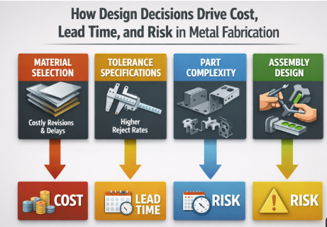
क्या आपने कभी एक प्रोटोटाइप का कोटेशन प्राप्त किया है जिसने आपके डिज़ाइन के बारे में आपके सभी प्रश्न उठा दिए? आप अकेले नहीं हैं। $200 के प्रोटोटाइप और $2,000 के प्रोटोटाइप के बीच का अंतर अक्सर उन निर्णयों पर निर्भर करता है जो आपके द्वारा RFQ जमा करने से काफी पहले लिए जाते हैं। कस्टम धातु प्रोटोटाइपिंग लागतों को प्रभावित करने वाले कारकों को समझना आपको उन बुद्धिमान समझौतों को करने में सक्षम बनाता है जिनमें आवश्यक कार्यक्षमता को बिना किसी समझौते के बनाए रखा जा सके।
प्रोटोटाइप मूल्य निर्धारण मनमाना नहीं है—यह सामग्री चयन, डिज़ाइन जटिलता, मात्रा, फिनिशिंग आवश्यकताओं और समय सीमा के दबाव के आधार पर भविष्यवाणि योग्य पैटर्न का अनुसरण करता है। आइए प्रत्येक कारक को विस्तार से समझें ताकि आप जमा करने से पहले लागतों की भविष्यवाणी कर सकें और अपने बजट को अनुकूलित कर सकें।
प्रोटोटाइपिंग लागतों को ऊँचा क्यों करते हैं?
प्रोटोटाइप मूल्य निर्धारण को एक सूत्र के रूप में सोचें जिसमें कई चर होते हैं। एक इनपुट में परिवर्तन करने से आउटपुट भी बदल जाता है—कभी-कभी काफी अधिक। ये वे प्राथमिक लागत ड्राइवर हैं जिन्हें आपको समझना आवश्यक है:
- सामग्री चयन: आप जो मिश्र धातु निर्दिष्ट करते हैं, वह सीधे कच्चे माल की लागत और मशीनिंग समय को प्रभावित करती है। HD Proto के अनुसार, 6061-T6 जैसी एल्यूमीनियम मिश्र धातुएँ आमतौर पर सबसे सस्ता विकल्प होती हैं, जिसके बाद प्लास्टिक और फिर स्टेनलेस स्टील आती है। टाइटेनियम, इनकोनेल या टूल स्टील जैसी उच्च-प्रदर्शन मिश्र धातुओं की कीमत बहुत अधिक होती है, क्योंकि इनके कच्चे माल की कीमत अधिक होती है और इन्हें मशीन करने के लिए विशेष उपकरणों की आवश्यकता होती है। 6061 एल्यूमीनियम से बने एक भाग की कीमत, उसी ज्यामिति के 316 स्टेनलेस स्टील के भाग की कीमत की तुलना में एक तिहाई हो सकती है।
- मशीनिंग समय: सीएनसी दुकानें प्रति घंटे के आधार पर बिल करती हैं। अनुसार Geomiq , मशीनिंग समय अंतिम लागत गणना में सबसे प्रभावशाली कारक माना जाता है। आपका भाग जितनी देर तक मशीन पर रहता है, उतना ही आपके बिल में जोड़ा जाता है। कठोर सामग्रियों के लिए काटने की गति धीमी होनी चाहिए, जिससे चक्र समय बढ़ जाता है। एक स्टेनलेस स्टील के भाग को मशीन करने में एक समकक्ष एल्यूमीनियम घटक की तुलना में तीन गुना अधिक समय लग सकता है।
- ज्यामिति जटिलता: जटिल डिज़ाइनों के लिए अधिक टूल परिवर्तन, सेटअप और सावधानीपूर्ण प्रोग्रामिंग की आवश्यकता होती है। गहरे कोनों के लिए लंबे टूलों का उपयोग करना पड़ता है, जो धीमी गति से चलते हैं। मानक टूल त्रिज्या से छोटे आंतरिक कोनों के लिए ईडीएम (EDM) संचालन की आवश्यकता हो सकती है, जो प्रीमियम दरों पर किए जाते हैं। सरल प्रिज़्मैटिक आकृतियों की लागत, जैविक या मूर्तिकारी ज्यामितियों की तुलना में काफी कम होती है।
- सहिष्णुता आवश्यकताएँ: यहाँ कई इंजीनियर अनजाने में अपने बजट को बढ़ा देते हैं। कड़ी टॉलरेंस के लिए धीमी कटिंग गति, अधिक सटीक फिनिशिंग पास और बार-बार गुणवत्ता निरीक्षण की आवश्यकता होती है। अधिकांश अनुप्रयोगों के लिए ±0.127 मिमी की मानक टॉलरेंस पर्याप्त है। जब केवल दो विशेषताओं को ही ±0.025 मिमी की सटीकता की आवश्यकता हो, तो प्रत्येक आयाम के लिए इस टॉलरेंस को निर्दिष्ट करना काफी मात्रा में धन का अपव्यय है।
- सामग्री अपव्यय: सीएनसी मशीनिंग एक घटात्मक प्रक्रिया है—आपके बिलेट से जो कुछ भी हटाया जाता है, वह सभी चिप्स के रूप में समाप्त हो जाता है। भाग की जटिलता के आधार पर, अपशिष्ट मूल ब्लैंक के आयतन का 30% से 70% तक हो सकता है। मानक स्टॉक आकारों के भीतर कुशल रूप से नेस्ट किए गए डिज़ाइन इस अपशिष्ट दंड को कम करते हैं।
मात्रा विचार और सेटअप लागत वितरण
यह विरोधाभासी लग सकता है, लेकिन अधिक भागों का ऑर्डर देने से आपकी प्रति-इकाई लागत अक्सर काफी कम हो जाती है। क्यों? क्योंकि प्रारंभिक महत्वपूर्ण व्यय—जैसे प्रोग्रामिंग, फिक्सचर सेटअप और सामग्री तैयारी—एक या सौ भागों के निर्माण के बावजूद स्थिर रहते हैं।
एकल प्रोटोटाइप के लिए, उस भाग पर पूरी सेटअप लागत आती है। दस इकाइयाँ ऑर्डर करने पर, ये स्थिर लागत अधिक भागों पर वितरित हो जाती हैं। जियोमिक के विश्लेषण के अनुसार, एक के बजाय 10 इकाइयाँ ऑर्डर करने से प्रति-इकाई लागत में 70% की कमी आ सकती है, जबकि 100 इकाइयों तक के पैमाने पर बढ़ाने से प्रति-इकाई मूल्य में 90% की कमी हो सकती है।
यह गणित विशेष रूप से तब प्रासंगिक हो जाता है जब आपको कई पुनरावृत्तियों की आवश्यकता होती है। एक प्रोटोटाइप का ऑर्डर देने, उसका परीक्षण करने और फिर दूसरा ऑर्डर देने के बजाय, एक साथ तीन या चार विविधताओं का ऑर्डर देने पर विचार करें। अतिरिक्त भाग की सीमांत लागत अक्सर सेटअप बचत की तुलना में नगण्य होती है।
परिष्करण आवश्यकताएँ और उनका बजट प्रभाव
कच्चे मशीन किए गए भागों को आमतौर पर सीधे ग्राहकों को नहीं भेजा जाता है। समाप्ति संचालन आपके प्रोटोटाइप की रक्षा करते हैं और उसकी उपस्थिति को बढ़ाते हैं—लेकिन वे लागत और नेतृत्व समय भी बढ़ाते हैं।
PTSMAKE के अनुसार, एनोडाइज़िंग आमतौर पर सीएनसी मशीन किए गए भाग की कुल लागत में 5% से 15% तक की वृद्धि करती है, जिसकी अंतिम कीमत एनोडाइज़िंग के प्रकार, कोटिंग की मोटाई, भाग के आकार और मास्किंग आवश्यकताओं पर निर्भर करती है। प्रकार III हार्डकोट एनोडाइज़िंग की लागत प्रमाणित प्रकार II से अधिक होती है, क्योंकि इसमें प्रसंस्करण का समय अधिक लगता है और तापमान नियंत्रण की आवश्यकता अधिक कठोर होती है।
पाउडर कोटिंग सेवाएँ लगभग किसी भी रंग में टिकाऊ, आकर्षक फिनिश प्रदान करती हैं। लागत भाग के आकार और बैच मात्रा पर निर्भर करती है। एनोडाइज़्ड एल्यूमीनियम एकीकृत रंग प्रदान करता है जो छिलने या उखड़ने के लिए प्रवण नहीं होता है—उपभोक्ता उत्पादों के लिए आदर्श—जबकि पाउडर कोट औद्योगिक अनुप्रयोगों के लिए उपयुक्त मोटी सुरक्षात्मक परतें प्रदान करता है।
विचार करें कि क्या आपका प्रोटोटाइप वास्तव में उत्पादन-स्तरीय समाप्ति की आवश्यकता है। एक कार्यात्मक परीक्षण भाग के लिए केवल मूल स्तर का डीबरिंग आवश्यक हो सकता है, जबकि ग्राहक के सामने प्रदर्शन के लिए पूर्ण समाप्ति की आवश्यकता होती है। प्रोटोटाइप के उद्देश्य के अनुसार समाप्ति पर निवेश को समायोजित करें।
त्वरित कार्य के लिए नेतृत्व समय प्रीमियम
समय कीमत के बराबर होता है—शाब्दिक रूप से। त्वरित प्रोटोटाइप की उच्च कीमत होती है क्योंकि वे कतार में छलांग लगाते हैं, अतिरिक्त समय के लिए श्रम की आवश्यकता होती है, और सामग्री या पूर्ण भागों के लिए वायु परिवहन की आवश्यकता हो सकती है।
मानक नेतृत्व समय निर्माताओं को समान नौकरियों को बैच में एकत्र करने, मशीन अनुसूची को अनुकूलित करने और सामग्री को आर्थिक रूप से प्राप्त करने की अनुमति देता है। जल्दी के आदेश इन दक्षताओं को बाधित करते हैं। यदि आप समय सीमा को अधिक कठोरता से संकुचित करते हैं, तो त्वरित टर्नअराउंड के लिए 25% से 100% या अधिक के प्रीमियम की अपेक्षा करें।
अपने प्रोटोटाइप बजट को अनुकूलित करने के लिए रणनीतियाँ
लागत ड्राइवर्स की समझ के साथ सुसज्जित होकर, आप ऐसे रणनीतिक निर्णय ले सकते हैं जो महत्वपूर्ण कार्यक्षमता को संकट में डाले बिना व्यय को कम करते हैं:
- हो सके तो ज्यामिति को सरल बनाएं: अनावश्यक सुविधाओं, सजावटी तत्वों या उन जटिलताओं को हटा दें जो कार्यात्मक परीक्षण के लिए आवश्यक नहीं हैं। प्रत्येक जेब, छिद्र और आकृति मशीनिंग समय बढ़ाती है।
- रिक्ति को रणनीतिक रूप से निर्दिष्ट करें: केवल कार्यात्मक रूप से महत्वपूर्ण आयामों पर ही कड़ी सहिष्णुता (टॉलरेंस) लागू करें। गैर-महत्वपूर्ण विशेषताओं को मानक वर्कशॉप सहिष्णुता पर छोड़ दें। यह एकमात्र परिवर्तन अक्सर सबसे बड़ी लागत कमी प्रदान करता है।
- उचित सामग्री का चयन करें: जब 304 स्टेनलेस स्टील पर्याप्त हो, तो 316 स्टेनलेस स्टील का निर्दिष्टीकरण न करें। जब एल्युमीनियम आपके डिज़ाइन को समान रूप से मान्य कर सकता हो, तो टाइटेनियम का मशीनिंग न करें। विदेशी सामग्रियों का उपयोग केवल उत्पादन-उद्देश्य परीक्षण के लिए सुरक्षित रखें।
- सामग्री की मोटाई पर ध्यानपूर्ण विचार करें: शीट मेटल प्रोटोटाइप के लिए, 14 गेज स्टील मोटाई (0.075") या 11 गेज स्टील मोटाई (0.120") जैसे मानक गेज कीमत में कम होते हैं, क्योंकि विशेष ऑर्डर की आवश्यकता वाली कस्टम मोटाई की तुलना में इन्हें आसानी से उपलब्ध कराया जा सकता है। मानक स्टॉक के आसपास डिज़ाइन करने से सामग्री लागत और लीड टाइम दोनों कम हो जाते हैं।
- अपने फिनिशिंग को उचित आकार में चुनें: सतह के फिनिश को वास्तविक आवश्यकताओं के अनुरूप समायोजित करें। बीड-ब्लास्ट किए गए भाग की लागत, बहु-चरणीय पॉलिशिंग की आवश्यकता वाले भाग की तुलना में काफी कम होती है। मानक 3.2 µम आरए सतह की रफनेस अधिकांश अनुप्रयोगों को अतिरिक्त प्रसंस्करण के बिना संतुष्ट करती है।
- आगे की योजना बनाएं: जब आप अपने कार्यक्रम में पर्याप्त लीड टाइम को शामिल करते हैं, तो जल्दीबाजी के शुल्क समाप्त हो जाते हैं। दो सप्ताह की योजना निर्माण लागत में 50% की बचत करा सकती है।
- स्पष्ट रूप से संवाद करें: अस्पष्ट ड्रॉइंग्स प्रश्न उत्पन्न करती हैं, देरी का कारण बनती हैं और कभी-कभी गलत भागों का निर्माण करा देती हैं। स्पष्ट विनिर्देशों के साथ पहचाने गए महत्वपूर्ण विशेषताएँ पीछे-आगे की बातचीत को कम करती हैं और महंगे पुनर्कार्य को रोकती हैं।
लागत और गुणवत्ता के बीच संतुलन सिर्फ कोनों काटने के बारे में नहीं है—यह तो अपने बजट का निवेश उन स्थानों पर करने के बारे में है जहाँ यह सबसे अधिक महत्वपूर्ण है। एक प्रोटोटाइप जिसकी लागत दोगुनी हो, लेकिन जो डिज़ाइन संबंधी प्रश्नों के दोगुने सत्यापन करे, उसका मूल्य उस सस्ते भाग से कहीं अधिक होता है जो किसी भी प्रश्न का उत्तर नहीं देता।
लागत ड्राइवर्स को समझना आपको यथार्थवादी बजट योजना के लिए तैयार करता है। लेकिन समयसीमा की अपेक्षाएँ अक्सर उतनी ही चुनौतीपूर्ण साबित होती हैं—विशेष रूप से जब परियोजना के कार्यक्रम संकुचित हो जाते हैं और हितधारक त्वरित परिणामों की माँग करते हैं।
नेतृत्व समय की अपेक्षाएँ और गति के कारकों का पलटाव
आपका प्रोटोटाइप वास्तव में कब आएगा? यह प्रश्न तंग विकास कार्यक्रम का सामना कर रहे इंजीनियरों को परेशान करता रहता है। आपके खरीद आदेश पर उल्लिखित नेतृत्व समय दुर्भाग्यवश अक्सर पूरी कहानी नहीं बताता है। फ़ाइल सबमिशन और भागों के हाथ में आने के बीच, कई कारक आपके समय-सीमा को विस्तारित या संकुचित कर सकते हैं, जिससे अतैयार टीमों को अप्रत्याशित रूप से चौंकाया जा सकता है।
वास्तविक पलटाव समय की अपेक्षाओं को समझना—और डिलीवरी को तेज़ करने के लिए आप जिन नियंत्रणों का उपयोग कर सकते हैं—उन परियोजनाओं को अलग करता है जो मील के पत्थरों को प्राप्त करती हैं, और उन परियोजनाओं से जो हितधारकों को देरी की व्याख्या करने में अटक जाती हैं।
विधि के आधार पर वास्तविक नेतृत्व समय की अपेक्षाएँ
विभिन्न निर्माण विधियाँ मौलिक रूप से भिन्न समय-सीमाओं पर कार्य करती हैं। यूनियनफैब के अनुसार, निर्माण दृष्टिकोण आपको तैयार भागों की प्राप्ति की गति को काफी प्रभावित करता है। सीएनसी मशीनिंग या 3D प्रिंटिंग के माध्यम से तीव्र धातु प्रोटोटाइपिंग सबसे तेज़ पलटाव समय प्रदान करती है, जबकि ढलाई के लिए धैर्य की आवश्यकता होती है।
ऐसी विविधता क्यों है? सेटअप आवश्यकताएँ बहुत अधिक भिन्न होती हैं। सीएनसी मशीनिंग और धातु 3डी प्रिंटिंग के लिए उत्पादन शुरू करने से पहले केवल कुछ घंटों के प्रोग्रामिंग की आवश्यकता होती है। शीट मेटल फॉर्मिंग के लिए टूलिंग और बेंड प्रोग्राम तैयार करने में 5–10 कार्यदिवस लगते हैं। इन्वेस्टमेंट कास्टिंग के लिए 2–6 सप्ताह की आवश्यकता होती है, क्योंकि मॉल्ड बनाना—यहाँ तक कि 3डी-प्रिंटेड पैटर्न का उपयोग करने पर भी—समय लेता है।
निम्नलिखित तुलना वास्तविक आधारभूत अपेक्षाओं को प्रदान करती है:
| विधि | मानक लीड टाइम | त्वरित विकल्प | प्रमुख देरी कारक |
|---|---|---|---|
| सीएनसी मशीनिंग | 7–12 कार्यदिवस | 3-5 कार्य दिवस | जटिल ज्यामितियाँ, दुर्लभ सामग्रियाँ, कठोर सहिष्णुताएँ |
| मेटल 3D प्रिंटिंग | 3-7 कार्य दिवस | 2-3 व्यापारिक दिन | पोस्ट-प्रोसेसिंग आवश्यकताएँ, बड़े निर्माण आयतन |
| चादर धातु निर्माण | 3–14 कार्यदिवस | 2-5 कार्यदिवस | टूलिंग सेटअप, जटिल बेंड अनुक्रम, वेल्डिंग परिचालन |
| निवेश मोल्डिंग | 2-6 सप्ताह | 10-15 बिजनेस दिन | मॉल्ड निर्माण, सामग्री का ठोसीकरण, कास्टिंग के बाद की मशीनिंग |
इन समयसीमाओं को केवल निर्माण के लिए माना जाता है। इनमें सामग्री की आपूर्ति में देरी, परिष्करण संचालन या शिपिंग शामिल नहीं हैं। त्वरित शीट धातु प्रोटोटाइपिंग निर्माण को तीन दिनों में पूरा कर सकती है, लेकिन पाउडर कोटिंग जोड़ने से कुल टर्नअराउंड समय एक से तीन दिन और बढ़ जाता है। पैसिवेशन की आवश्यकता वाले स्टेनलेस स्टील शीट धातु भागों के लिए सतह उपचार के लिए समान समय की आवश्यकता होती है।
वास्तव में आपकी समयसीमा को क्या बढ़ाता है
उद्धृत लीड टाइम और वास्तविक डिलीवरी अक्सर एक-दूसरे से भिन्न होती हैं। इसके कारणों को समझना आपको उन कारकों से बचने में मदद करता है जो परियोजनाओं को निर्धारित समय सीमा के बाद धकेल देते हैं।
- सामग्री की उपलब्धता: मानक एल्यूमीनियम और स्टील मिश्र धातुएँ आमतौर पर वितरकों से कुछ दिनों के भीतर शिप की जाती हैं। विशेष प्रकार की सामग्री—टाइटेनियम ग्रेड, उच्च-निकल सुपरअलॉय, असामान्य मोटाई—को स्रोत करने में सप्ताह लग सकते हैं। EVS मेटल के अनुसार, अनुभवी फैब्रिकेटर्स दक्ष सामग्री प्राप्ति सुनिश्चित करने के लिए विश्वसनीय आपूर्तिकर्ताओं के साथ संबंध बनाए रखते हैं, लेकिन असामान्य विशिष्टताएँ फिर भी देरी पैदा करती हैं।
- डिज़ाइन जटिलता: अधिक सुविधाएँ अर्थात् अधिक मशीन समय, अधिक सेटअप और मुद्दों के लिए अधिक अवसर जिनके हस्तक्षेप की आवश्यकता होती है। एक साधारण ब्रैकेट को पूरा करने में घंटों लग सकते हैं; जबकि दर्जनों थ्रेडेड छिद्रों और कड़ी सहिष्णुता वाले बोर के साथ एक जटिल मैनिफोल्ड मशीन को दिनों तक व्यस्त रख सकता है।
- फिनिशिंग संचालन: प्रोटोलिस के अनुसार, फिनिशिंग कुल परियोजना अवधि को काफी प्रभावित करती है। पेंटिंग और पाउडर कोटिंग में १-३ दिन लगते हैं। एनोडाइज़िंग, क्रोम प्लेटिंग या गैल्वनाइज़िंग जैसे सतह उपचारों के लिए २-४ दिन की आवश्यकता होती है। ग्राहक के सामने उपयोग के लिए भागों के लिए सौंदर्यपूर्ण फिनिशिंग में १-२ दिन लगते हैं। ये अवधियाँ संयोजित हो जाती हैं—एक ऐसा भाग जिसे मशीनिंग और एनोडाइज़िंग दोनों की आवश्यकता होती है, वह दोनों लीड टाइम्स को अपने में समाहित कर लेता है।
- पुनरावृत्ति चक्र: आपके फैब्रिकेटर द्वारा पूछा गया प्रत्येक प्रश्न घड़ी को रोक देता है। अपूर्ण ड्रॉइंग्स, अस्पष्ट आयाम या अस्पष्ट सामग्री विनिर्देशन RFI (सूचना के लिए अनुरोध) को ट्रिगर करते हैं, जिनके स्पष्टीकरण के लिए प्रतीक्षा करने में दिनों लग सकते हैं। जब ईमेल विनिर्देशन के अंतर को सुलझाने के लिए बैक एंड फोर्थ होते हैं, तो त्वरित टर्न शीट मेटल फैब्रिकेशन धीमे टर्न में बदल जाता है।
अपने प्रोटोटाइप के समय-सीमा को कैसे त्वरित करें
क्या आप समय-सीमा के दबाव में महसूस कर रहे हैं? ये रणनीतियाँ वास्तव में डिलीवरी को तेज़ करती हैं, न कि केवल लागत को स्थानांतरित करती हैं:
- पूर्ण और स्पष्ट फ़ाइलें जमा करें: प्रोटोलिस के अनुसार, आपका अनुरोध जितना सटीक होगा—जिसमें सामग्री, फ़िनिश और प्रौद्योगिकी विनिर्देश शामिल हों—उतनी ही तेज़ी से प्रतिक्रिया मिलेगी। स्पष्ट आयामों के साथ अनुकूलित ड्रॉइंग्स DFM समीक्षा समय को काफी कम कर देती हैं। ऐसे निर्माता जिन्हें कोई प्रश्न नहीं पूछना पड़ता, धातु काटना जल्दी शुरू कर देते हैं।
- आदेश देने से पहले सामग्री की उपलब्धता की पुष्टि करें: अपने निर्माता से उद्धरण के दौरान स्टॉक की स्थिति के बारे में पूछें। चार सप्ताह के विशेष मिश्र धातु से एक तत्काल उपलब्ध विकल्प पर स्विच करने से आपकी समय-सीमा समस्या तुरंत हल हो सकती है।
- फ़िनिशिंग आवश्यकताओं को सरल बनाएँ: क्या आपको भाग जल्दी चाहिए? परीक्षण के लिए अस-मशीन्ड या बीड-ब्लास्टेड सतहों को स्वीकार करें। जब समय-सीमा का दबाव कम हो जाए, तो बाद के संस्करणों के लिए दृश्यिक फ़िनिश का आरक्षण करें।
- समानांतर निर्माण पर विचार करें: कई प्रोटोटाइप विविधताएँ अक्सर एक साथ चल सकती हैं। क्रमिक रूप से पुनरावृत्ति करने के बजाय, एक साथ तीन डिज़ाइन विकल्पों का आदेश दें। अतिरिक्त लागत आमतौर पर बचाए गए समय की तुलना में काफी कम सिद्ध होती है।
- त्वरित प्रोटोटाइपिंग शीट धातु विधियों का रणनीतिक रूप से चयन करें: जब ज्यामिति अनुमति देती है, तो शीट धातु निर्माण और धातु 3D मुद्रण भौतिक भागों के लिए सबसे तेज़ मार्ग प्रदान करते हैं। इन विधियों के माध्यम से त्वरित धातु प्रोटोटाइपिंग, उचित योजना बनाने पर, एक सप्ताह से भी कम समय में कार्यात्मक प्रोटोटाइप प्रदान कर सकती है।
विकास कार्यक्रमों के भीतर प्रोटोटाइप की योजना बनाना
स्मार्ट प्रोजेक्ट प्रबंधक मील के पत्थर की समय सीमा से पीछे की ओर प्रोटोटाइप के समय-सारणी का निर्माण करते हैं। यदि आपकी डिज़ाइन समीक्षा के लिए 15 मार्च को भौतिक भागों की आवश्यकता है, तो आपको फ़ाइलें कब सौंपनी चाहिए?
गणना स्पष्ट और ईमानदारी से करें:
- शिपिंग: 2–5 दिन (घरेलू भूमि मार्ग) या 1–2 दिन (त्वरित)
- फ़िनिशिंग: आवश्यकताओं के आधार पर 1–4 दिन
- निर्माण: विधि और जटिलता के आधार पर 3–14 दिन
- DFM समीक्षा और कोटेशन: 1–3 दिन
- फ़ाइल तैयारी और आंतरिक समीक्षा: 2-5 दिन (यहां पूरी ईमानदारी बरतें)
अचानक वह 15 मार्च की समयसीमा बीच-फरवरी में डिज़ाइन फ़ाइलें जमा करने का अर्थ रखती है—जो कि आशावादी योजनाकारों द्वारा अकसर शुरुआती मार्च मानी जाती है।
अप्रत्याशित घटनाओं के लिए बफर का निर्माण करें। सामग्री की कमी, मशीन की खराबी और विनिर्देशन संबंधी समस्याएं होती रहती हैं। दो सप्ताह के बफर वाले प्रोजेक्ट इन व्यवधानों को सहन कर लेते हैं; जबकि संभवता की सीमा पर चल रहे प्रोजेक्ट त्वरित शुल्क और योजनाबद्ध मील के पत्थरों के अतिक्रमण के कारण विफल हो जाते हैं।
लीड टाइम की वास्तविकताओं को समझना आपको अनुसूची निर्धारण की सफलता के लिए तैयार करता है। लेकिन यहां तक कि सही समयरेखा योजना भी उन रोके जा सकने वाली गलतियों की भरपाई नहीं कर सकती जो कस्टम धातु प्रोटोटाइपिंग प्रोजेक्ट्स को विफल कर देती हैं—डिज़ाइन, विनिर्देशन और संचार में त्रुटियाँ, जिनसे अनुभवी इंजीनियर बचना सीख जाते हैं।
सामान्य प्रोटोटाइपिंग त्रुटियाँ और उनसे बचने के तरीके
क्या आपके पास कभी एक प्रोटोटाइप आया है जो आपके CAD मॉडल के समान बिल्कुल भी नहीं दिखता था? या क्या आपको एक इतना ऊँचा अनुमान मिला है कि आप सोचने लगे कि कहीं फैब्रिकेटर ने आपकी फ़ाइल गलत पढ़ तो नहीं ली? ये निराशाजनक परिणाम शायद ही कभी निर्माण की अक्षमता से उत्पन्न होते हैं। अधिकांशतः, ये तब होते हैं जब धातु को मशीन से मिलने से पहले ही रोके जा सकने वाली त्रुटियाँ की जाती हैं।
डिज़ाइन के उद्देश्य और निर्मित वास्तविकता के बीच का अंतर तब बढ़ जाता है जब इंजीनियर प्रोटोटाइपिंग शीट धातु और मशीन किए गए घटकों को नियंत्रित करने वाली भौतिक सीमाओं को नज़रअंदाज़ कर देते हैं। इन सामान्य गलतियों को समझना—और सरल रोकथाम रणनीतियों को लागू करना—चिकने प्रोजेक्ट्स और महंगे सीखने के अनुभवों के बीच अंतर करता है।
आपके प्रोटोटाइप को देरी करने वाली डिज़ाइन त्रुटियाँ
सीएडी सॉफ्टवेयर आपको कल्पना की जा सकने वाली किसी भी वस्तु का मॉडल बनाने की अनुमति देता है। दुर्भाग्यवश, प्रेस ब्रेक, सीएनसी मिल और लेज़र कटर भौतिक सीमाओं के भीतर काम करते हैं, जिन्हें आपकी स्क्रीन अनदेखा कर देती है। सेंडकटसेंड के अनुसार, किसी भाग को डिज़ाइन करने में अपना पसीना लगाने के बाद उसे ऐसी स्थिति में प्राप्त करना, जहाँ मोड़ अंत में विकृत हो जाएँ, सतह पर दरारें पड़ जाएँ या फ्लैंज़ इतने विकृत हो जाएँ कि वे उपयोग के अयोग्य हो जाएँ— यह बहुत ही निराशाजनक होता है।
ये वे डिज़ाइन त्रुटियाँ हैं जो शीट मेटल प्रोटोटाइप्स को सबसे अधिक बार विफल कर देती हैं:
- पर्याप्त बेंड रिलीफ का अभाव: जब दो मोड़ रेखाएँ उचित राहत कट (रिलीफ कट) के बिना एक-दूसरे को काटती हैं, तो सामग्री अप्रत्याशित रूप से फट जाती है या विकृत हो जाती है। मोड़ राहत (बेंड रिलीफ) मोड़ने के दौरान नियंत्रित सामग्री प्रवाह की अनुमति देती है, जिससे उच्च-तनाव क्षेत्रों में फटने या दरार पड़ने के जोखिम को कम किया जाता है। इसके बिना, आप विकृत कोनों और कमज़ोर संरचनात्मक अखंडता को देखेंगे।
- गलत मोड़ अनुमति: धातु को मोड़ने पर वह फैल जाती है। यदि आपका CAD सॉफ्टवेयर डिफ़ॉल्ट बेंड अलाउंस वैल्यूज़ का उपयोग करता है जो आपकी वास्तविक सामग्री और मोटाई के अनुरूप नहीं हैं, तो अंतिम आयाम गलत हो जाएँगे। सटीक फ्लैट पैटर्न विकास के लिए हमेशा अपने CAD को फैब्रिकेटर के विशिष्ट k-फैक्टर और बेंड रेडियस के अनुसार कॉन्फ़िगर करें।
- न्यूनतम फ्लैंज लंबाई के उल्लंघन: सफल बेंडिंग के लिए प्रेस ब्रेक डाइज़ को दो बिंदुओं पर पर्याप्त संपर्क की आवश्यकता होती है। उदाहरण के लिए, 0.250" स्टेनलेस स्टील के लिए बेंड से पहले न्यूनतम फ्लैंज लंबाई 1.150" की आवश्यकता होती है, जबकि पतली 0.040" एल्यूमीनियम के लिए 0.255" जितनी छोटी फ्लैंज भी पर्याप्त हो सकती है। इन सीमाओं की अनदेखी करने से भागों के फिसलने और असंगत बेंड्स की समस्या उत्पन्न होती है।
- छिद्र से किनारे तक की अनुचित दूरी: बेंड के बहुत पास स्थित विशेषताएँ फॉर्मिंग के दौरान विकृत हो जाती हैं। लेज़र कटिंग के कर्फ से पहले ही सामग्री हटा दी जाती है; यदि इसके पास ही बेंडिंग के बल लगाए जाएँ, तो छिद्र अंडाकार हो जाते हैं, किनारे विकृत हो जाते हैं और महत्वपूर्ण विशेषताओं की आयामिक सटीकता खो जाती है। बेंड लाइनों से कम से कम 2–3 गुना सामग्री की मोटाई की दूरी बनाए रखें।
- उपकरण टक्कर: जटिल ज्यामितीय आकृतियाँ मोड़ने के क्रम के दौरान प्रेस ब्रेक औजारों के साथ हस्तक्षेप कर सकती हैं। स्व-टक्कर (सेल्फ-कॉलिज़न) तब होती है जब भाग का एक भाग आकृति निर्माण के दौरान दूसरे भाग को स्पर्श करता है। सेंडकटसेंड के अनुसार, ये टक्करें तब होती हैं जब भाग बहुत संकरे होते हैं, फ्लैंज़ बहुत लंबे होते हैं, या मोड़ने के क्रम से ज्यामितीय हस्तक्षेप उत्पन्न होता है।
विशिष्टता त्रुटियाँ और उन्हें रोकने के तरीके
यहाँ तक कि सही ज्यामिति भी विफल हो जाती है जब विशिष्टताएँ स्पष्ट करने के बजाय भ्रमित करती हैं। अनुसार स्विट्ज़र निर्माण , इंजीनियर अक्सर ऐसी भविष्यवाणि योग्य त्रुटियाँ करते हैं जो निर्माणीयता को समाप्त कर देती हैं, लागत को बढ़ा देती हैं, या कार्यात्मक आवश्यकताओं को पूरा नहीं करने वाले भागों का परिणाम देती हैं—आमतौर पर अन्य प्रक्रियाओं से डिज़ाइन सिद्धांतों को लागू करने से, जबकि उन मूलभूत अंतरों को पहचाने बिना।
- अत्यधिक सहिष्णुता निर्धारित करना: प्रत्येक आयाम पर ±0.025 मिमी की सहिष्णुता लागू करना, जबकि केवल दो विशेषताओं की ही इतनी सटीकता की आवश्यकता होती है, महत्वपूर्ण बजट की बर्बादी करता है। कठोर सहिष्णुताएँ धीमी कटिंग गति, अधिक फिनिशिंग पास और बार-बार निरीक्षण की आवश्यकता रखती हैं। केवल उन्हीं स्थानों पर कठोर सहिष्णुताएँ निर्दिष्ट करें जहाँ कार्यात्मक आवश्यकता उन्हें माँगती है।
- महत्वपूर्ण विशेषताओं के लिए कम सहनशीलता (अंडर-टॉलरेंसिंग): विपरीत त्रुटि भी उतनी ही समस्याजनक सिद्ध होती है। स्पष्ट सहनशीलता निर्देशों के बिना, निर्माता मानक सहनशीलता लागू करते हैं, जो आपके महत्वपूर्ण आयामों की आवश्यकताओं की तुलना में कम सख्त हो सकती हैं। एक माउंटिंग होल जिसे सटीक रूप से संलग्न भागों के साथ संरेखित करने की आवश्यकता होती है, उसके लिए स्पष्ट विनिर्देशन की आवश्यकता होती है।
- महत्वपूर्ण आयाम निर्देशों का अभाव: दर्जनों आयामों के साथ ड्रॉइंग्स जिन पर समान सहनशीलता दी गई हो, वे प्राथमिकताओं के बारे में कोई मार्गदर्शन प्रदान नहीं करती हैं। कार्य के लिए महत्वपूर्ण विशेषताओं को हाइलाइट करें। विशिष्ट सहनशीलताओं के महत्व को स्पष्ट करने वाले नोट्स शामिल करें—यह संदर्भ निर्माण की चुनौतियों के कारण विनिर्देशों के लिए वैकल्पिक समाधान सुझाने में निर्माताओं की सहायता करता है।
- सतह परिष्करण आवश्यकताओं का अस्पष्ट होना: आवश्यक सतह परिष्करण, किनारों की स्थिति या सौंदर्य संबंधी अपेक्षाओं को निर्दिष्ट न करने से ऐसे भाग तैयार होते हैं जो आयामी विनिर्देशों को पूरा करते हैं, लेकिन अन्य आवश्यकताओं को पूरा नहीं करते हैं। परिष्करण, लेपन और अंकन आवश्यकताओं के लिए स्पष्ट निर्देश देने से स्वीकार्य भागों के बारे में साझा समझ सुनिश्चित होती है।
- अपूर्ण सामग्री विनिर्देश: बिना ग्रेड, टेम्पर या मोटाई के निर्दिष्ट किए 'स्टेनलेस स्टील' का अनुरोध करना निर्माताओं को अनुमान लगाने पर मजबूर करता है। 304 और 316L स्टेनलेस स्टील के बीच का अंतर संक्षारण प्रतिरोध, वेल्डेबिलिटी और लागत को प्रभावित करता है। आवश्यकतानुसार पूर्ण रूप से निर्दिष्ट करें ताकि आपको ठीक वही मिले जिसकी आपको आवश्यकता है।
अपने निर्माता के साथ संचार के सर्वोत्तम अभ्यास
शायद सबसे हानिकारक गलती अकेले डिज़ाइन करना है। स्विट्ज़र निर्माण के अनुसार, आयामों और विशिष्टताओं को अंतिम रूप देने से पहले डिज़ाइन के चरण में निर्माता से परामर्श करने से संभावित समस्याओं की पहचान, अनुकूलन के अवसरों और उत्पादन योग्यता को बढ़ाने वाले डिज़ाइन सुधारों की पहचान की जा सकती है।
प्रभावी निर्माण प्रोटोटाइप संचार में शामिल है:
- प्रारंभिक संलग्नता: अंतिम रूप देने से पहले प्रारंभिक डिज़ाइन साझा करें। निर्माताओं के पास विधियों का गहन ज्ञान और उन चीजों के साथ व्यापक अनुभव होता है जो काम करती हैं और जो समस्याएं पैदा करती हैं। इस विशेषज्ञता का उपयोग प्रारंभिक सहयोग के माध्यम से करने से स्वतंत्र रूप से डिज़ाइन को अंतिम रूप देने की तुलना में बेहतर परिणाम प्राप्त होते हैं।
- स्पष्ट अनुप्रयोग संदर्भ: स्पष्ट करें कि ये भाग किन उद्देश्यों के लिए उपयोग किए जाएँगे, वे किन पर्यावरणीय परिस्थितियों का सामना करेंगे, और कौन-से गुणवत्ता मानक लागू होते हैं। केवल एक ड्रॉइंग से यह स्पष्ट नहीं होता कि सौंदर्यपूर्ण खरोंचों का महत्व है या नहीं, या कि भाग किसी संक्षारक वातावरण में कार्य करता है या नहीं।
- पहचाने गए महत्वपूर्ण विशेषताएँ: मान लेना न लें कि निर्माता जानते हैं कि कौन-से आयाम सबसे अधिक महत्वपूर्ण हैं। ड्रॉइंग्स और विशिष्टता दस्तावेज़ों में कार्य-संबंधी रूप से महत्वपूर्ण विशेषताओं को स्पष्ट रूप से पहचानें।
- प्रतिक्रियाशील स्पष्टीकरण: प्रत्येक RFI (सूचना के लिए अनुरोध) उत्पादन को रोक देता है। अनुसार निर्माता , CAD में मॉडलिंग की सुविधा और वास्तविक दुनिया के उत्पादन में कठिनाइयों के बीच का अंतर DFM (उत्पादन के लिए डिज़ाइन) संबंधी चिंताओं को जन्म देता है, जिनका समाधान आवश्यक है। परियोजना की गति बनाए रखने के लिए निर्माता के प्रश्नों के उत्तर त्वरित रूप से दें।
समस्याएँ उत्पन्न करने वाली फ़ाइल तैयारी की त्रुटियाँ
आपका प्रोटोटाइप उतना ही अच्छा है जितनी अच्छी फ़ाइल आपने जमा की है। सामान्य ज्यामितीय समस्याएँ इस प्रकार हैं:
- खुली सतहें: जो सतहें उचित रूप से जुड़ी नहीं होती हैं, वे ठोस सीमाओं के बारे में अस्पष्टता पैदा करती हैं। जमा करने से पहले सुनिश्चित करें कि सभी ज्यामिति जलरोधक (वॉटरटाइट) है।
- गलत मापन: मिलीमीटर के मॉडल को इंच के रूप में जमा करना—या इसके विपरीत—भागों को दस गुना बहुत बड़ा या छोटा बना देता है। सुनिश्चित करें कि आपकी फ़ाइल के शीर्षक में इकाइयाँ आपके इरादे के अनुरूप हों।
- ज्यामिति के बजाय एम्बेडेड पाठ: सीएडी फ़ाइलों में पाठ टिप्पणियाँ मशीन निर्देशों में अनुवादित नहीं होती हैं। किसी भी उत्कीर्णित पाठ को वास्तविक ज्यामिति में परिवर्तित करें।
- अत्यधिक जटिल विशेषताएँ: मशीन क्षमताओं से अधिक विशेषताएँ—जैसे अत्यधिक गहरे पॉकेट, उपकरण पहुँच के बिना आंतरिक अंडरकट, असंभव रूप से कसे हुए आंतरिक कोने—निर्माण समस्याएँ उत्पन्न करती हैं। 'द फैब्रिकेटर' के अनुसार, चिंता का कारण 3D में चीज़ों को मॉडल करने की सरलता और उन्हें वास्तविक जीवन में उत्पादित करने की कठिनाइयों के बीच का अंतर है।
- पूर्व-समायोजित आयाम: कुछ इंजीनियर, एटिंग में अंडरकट या लेज़र कटिंग में कर्फ के बारे में जानकारी प्राप्त करने के बाद, अपने आयामों को पूर्व-समायोजित कर लेते हैं। जब निर्माता फिर से मानक समायोजन लागू करता है, तो दोहरा समायोजन हो जाता है। हमेशा अंतिम वांछित आयामों को निर्दिष्ट करें—निर्माता को प्रक्रिया-उपयुक्त समायोजन लागू करने दें।
टालने योग्य सामग्री चयन त्रुटियाँ
गलत सामग्री का चयन करने से श्रृंखलाबद्ध समस्याएँ उत्पन्न होती हैं:
- आवश्यकता से अधिक मोटा: जब 0.015" सामग्री पर्याप्त ताकत प्रदान करती है, तो 0.030" सामग्री का उपयोग करने से पतले गेज के साथ संभव सटीक टॉलरेंस और सूक्ष्म विशेषताओं का लाभ खो जाता है, जबकि लागत में वृद्धि होती है।
- संरचनात्मक आवश्यकताओं के लिए बहुत पतला: ऐसे भाग जो निर्माण के दौरान बच जाते हैं, लेकिन असेंबली के दौरान मुड़ जाते हैं, विकृत हो जाते हैं या विफल हो जाते हैं, ये महंगी त्रुटियाँ हैं। सटीकता के लाभों को संरचनात्मक आवश्यकताओं के विरुद्ध संतुलित करें।
- उत्पादन-पश्चात प्रसंस्करण के लिए गलत टेम्पर: जब अनुप्रयोग में तंग-त्रिज्या वाले बेंडिंग का समावेश होता है, तो पूर्ण-कठोर स्प्रिंग टेम्पर सामग्री का अनुरोध करने से दरारें उत्पन्न हो सकती हैं। अपने पूर्ण निर्माण क्रम के अनुसार सामग्री की स्थिति को सुमेलित करें।
- प्रोटोटाइप धातु स्टैम्पिंग संक्रमणों को अनदेखा करना: यदि आपका प्रोटोटाइप उच्च-मात्रा वाली स्टैम्पिंग के लिए अभिप्रेत डिज़ाइन को मान्य करता है, तो ऐसी सामग्रियों का चयन करें जो प्रोटोटाइपिंग और उत्पादन फॉर्मिंग दोनों परिस्थितियों में समान रूप से व्यवहार करती हों।
इन सामान्य त्रुटियों से बचने के लिए आपको अपनी चुनी हुई प्रक्रिया की विशिष्ट विशेषताओं को समझना, उचित डिज़ाइन नियमों का अनुपालन करना, आवश्यकताओं को स्पष्ट रूप से निर्दिष्ट करना और निर्माताओं के साथ सहयोग करना आवश्यक है। यह दृष्टिकोण ऐसे भागों के निर्माण को सुनिश्चित करता है जो विश्वसनीय रूप से निर्मित हो सकें, कार्यात्मक आवश्यकताओं को पूरा कर सकें तथा प्रदर्शन, गुणवत्ता और लागत के बीच संतुलन को अधिकतम कर सकें।
जब त्रुटि-रोधी रणनीतियाँ लागू कर ली जाती हैं, तो आप विचार करने के लिए तैयार हो जाते हैं कि विभिन्न उद्योग कस्टम धातु प्रोटोटाइपिंग पर कैसे विशिष्ट आवश्यकताएँ लागू करते हैं—मानक और प्रमाणन जो आपके भागों के अंतिम संचालन स्थान के आधार पर काफी भिन्न हो सकते हैं।
उद्योग-विशिष्ट प्रोटोटाइपिंग आवश्यकताएँ और मानक
सभी धातु प्रोटोटाइप्स को समान सख्ती से जांचा नहीं जाता है। औद्योगिक मशीनरी के लिए एक ब्रैकेट की आवश्यकताएँ शल्य चिकित्सा उपकरण या विमान के लैंडिंग गियर घटक की आवश्यकताओं से भिन्न होती हैं। आपके प्रोटोटाइप की सेवा करने वाला क्षेत्र आपूर्ति श्रृंखला में धातु की ट्रेसेबिलिटी से लेकर प्रमाणन प्रलेखन तक सब कुछ निर्धारित करता है—और इन आवश्यकताओं को अनदेखा करने से महीनों के विकास कार्य की वैधता समाप्त हो सकती है।
जब आप किसी धातु भाग निर्माता के साथ सहयोग शुरू करने से पहले क्षेत्र-विशिष्ट आवश्यकताओं को समझ लेते हैं, तो यह महंगे पुनर्कार्य (रीवर्क) को रोकता है और यह सुनिश्चित करता है कि आपके प्रोटोटाइप्स उत्पादन-उद्देश्य के गुणवत्ता मानकों का सटीक प्रतिनिधित्व करें। आइए देखें कि प्रत्येक प्रमुख उद्योग को कस्टम धातु प्रोटोटाइपिंग साझेदारों से क्या आवश्यकताएँ हैं।
ऑटोमोटिव प्रोटोटाइप आवश्यकताएँ और प्रमाणन मानक
ऑटोमोटिव उद्योग कठोर गुणवत्ता प्रबंधन प्रणालियों के अधीन कार्य करता है, जो प्रोटोटाइप विकास तक विस्तारित होती हैं। अनुसार, IATF 16949 दिशानिर्देश , जब ग्राहक प्रोटोटाइप कार्यक्रमों की आवश्यकता रखते हैं, तो संगठनों को उत्पादन के लिए नियोजित आपूर्तिकर्ताओं, टूलिंग और निर्माण प्रक्रियाओं का उपयोग करना चाहिए—जहाँ तक संभव हो।
यह आपके चैसिस प्रोटोटाइप या सस्पेंशन घटक के लिए इसलिए महत्वपूर्ण क्यों है? क्योंकि वैधीकरण परीक्षण केवल तभी प्रासंगिक सिद्ध होता है जब प्रोटोटाइप वास्तव में उत्पादन की स्थितियों का प्रतिनिधित्व करते हों। बिलेट एल्युमीनियम से बनाया गया एक प्रोटोटाइप आपको यह नहीं बताता कि एक स्टैम्प्ड उत्पादन भाग समान भार के अधीन कैसे प्रदर्शन करेगा।
प्रमुख ऑटोमोटिव प्रोटोटाइपिंग आवश्यकताएँ इनमें शामिल हैं:
- IATF 16949 प्रमाणन: यह ऑटोमोटिव-विशिष्ट गुणवत्ता मानक डिज़ाइन नियंत्रण से लेकर आपूर्तिकर्ता प्रबंधन तक सभी को नियंत्रित करता है। IATF 16949-प्रमाणित स्टील फैब्रिकेटर्स के साथ काम करने से सुनिश्चित होता है कि आपके प्रोटोटाइप्स दस्तावेज़ित गुणवत्ता प्रक्रियाओं का पालन करते हैं, जो OEM आवश्यकताओं को पूरा करती हैं।
- उत्पादन-उद्देश्य प्रक्रियाएँ: प्रोटोटाइप नियंत्रण योजनाएँ उत्पादन विधियों को दर्शानी चाहिए। यदि आपका अंतिम भाग स्टैम्प किया जाना है, तो स्टैम्पिंग के माध्यम से प्रोटोटाइपिंग—भले ही प्रति टुकड़ा लागत अधिक हो—CNC मशीनिंग की तुलना में अधिक प्रासंगिक वैधीकरण डेटा प्रदान करती है।
- सामग्री ट्रेसेबिलिटी: ऑटोमोटिव OEM को कच्चे स्टॉक से अंतिम भागों तक की प्रलेखित सामग्री प्रमाणपत्रों की आवश्यकता होती है। यह ट्रेसैबिलिटी प्रोटोटाइप से लेकर उत्पादन तक मौजूद होनी चाहिए।
- प्रदर्शन परीक्षण निगरानी: आईएटीएफ आवश्यकताओं के अनुसार, संगठनों को सभी प्रदर्शन परीक्षण गतिविधियों की निगरानी करनी चाहिए ताकि समय पर पूर्णता और आवश्यकताओं के अनुपालन को सुनिश्चित किया जा सके। प्रोटोटाइपिंग के दौरान परीक्षण में देरी उत्पादन के समय-सारणी में विस्थापन का कारण बनती है।
संरचनात्मक ऑटोमोटिव घटकों के लिए तन्य सामर्थ्य आवश्यकताओं के कारण सामग्री का सावधानीपूर्ण चयन और सत्यापन आवश्यक होता है। चेसिस घटक, निलंबन ब्रैकेट और संरचनात्मक मजबूतीकरण को परीक्षण के माध्यम से दस्तावेज़ीकृत विशिष्ट यांत्रिक गुणों के दिए गए दहलीज़ मानों को पूरा करना आवश्यक है।
त्वरित प्रोटोटाइप मान्यीकरण की तलाश कर रही ऑटोमोटिव टीमों के लिए, 5-दिवसीय त्वरित प्रोटोटाइपिंग के साथ-साथ आईएटीएफ 16949 प्रमाणन प्रदान करने वाले निर्माता गति और गुणवत्ता अनुपालन के बीच के अंतर को पाटते हैं। शाओयी (निंगबो) मेटल टेक्नोलॉजी यह दृष्टिकोण को उदाहरणित करता है, जो व्यापक DFM समर्थन के साथ चेसिस और निलंबन प्रोटोटाइप प्रदान करता है तथा 12 घंटे के भीतर कोटेशन देने की क्षमता रखता है, जबकि ऑटोमोटिव प्रमाणन मानकों को बनाए रखता है।
एयरोस्पेस और चिकित्सा प्रोटोटाइपिंग पर विचार
एयरोस्पेस और चिकित्सा अनुप्रयोगों में सामग्री प्रमाणन, परिशुद्धता और दस्तावेज़ीकरण के लिए कठोर आवश्यकताएँ साझा की जाती हैं—हालाँकि उनकी विशिष्ट प्राथमिकताएँ काफी भिन्न होती हैं।
एयरोस्पेस प्रोटोटाइपिंग आवश्यकताएँ
प्रोटोलैब्स के अनुसंधान के अनुसार, एयरोस्पेस अनुप्रयोगों की विशेषता छोटे बैच आकार, निर्माता-विशिष्ट अनुकूलन, बहुत लंबे जीवन चक्र और अत्यधिक उच्च सुरक्षा आवश्यकताओं से होती है। घटक 30 वर्षों से अधिक समय तक सेवा में रह सकते हैं, जिन्हें उड़ान के दौरान उत्थान, अवतरण और जलवायु विक्षोभ के दौरान तापीय और यांत्रिक भार का सामना करना पड़ सकता है।
ये परिस्थितियाँ विशिष्ट प्रोटोटाइपिंग आवश्यकताओं को जन्म देती हैं:
- हल्के भार वाली सामग्री का अनुकूलन: एल्यूमीनियम वेल्डिंग तकनीकें और टाइटेनियम निर्माण एयरोस्पेस प्रोटोटाइपिंग को प्रभुत्व में रखते हैं। जब भाग दशकों तक सेवा के दौरान लाखों मील उड़ान भरते हैं, तो प्रत्येक ग्राम मायने रखता है।
- पूर्ण सामग्री परिवर्तनशीलता: प्रत्येक प्रोटोटाइप के साथ मिश्र धातु के संघटन, ऊष्मा उपचार और यांत्रिक गुणों के बारे में दस्तावेज़ीकरण करने वाले मिल प्रमाणपत्र अवश्य संलग्न होने चाहिए। यह दस्तावेज़ीकरण श्रृंखला सेवा के दौरान विफलताओं के होने पर मूल कारण विश्लेषण सक्षम करती है।
- अर्हता और प्रमाणन: प्रोटोलैब्स के अनुसार, अमेरिका मेक्स, अमेरिकी सैन्य बल और एफएए जैसी प्रमुख एयरोस्पेस कंपनियों और संगठनों द्वारा निजी और सार्वजनिक प्रयासों के माध्यम से अर्हता और प्रमाणन की बाधाओं को लगातार दूर किया जा रहा है।
- एडिटिव निर्माण का अपनाया जाना: धातु 3डी प्रिंटिंग को एयरोस्पेस क्षेत्र में विशेष रूप से अपनाया गया है, जहाँ जटिल ज्यामिति और कम मात्रा एडिटिव क्षमताओं के साथ पूर्णतः संरेखित हैं। पिछले दशक में उद्योग के कुल राजस्व के एक हिस्से के रूप में एयरोस्पेस में एडिटिव निर्माण का राजस्व लगभग दोगुना हो गया है।
चिकित्सा उपकरण प्रोटोटाइपिंग आवश्यकताएँ
चिकित्सा प्रोटोटाइप्स के सामने जैव-अनुकूलता और विसंक्रमण की विशिष्ट आवश्यकताएँ होती हैं। फिक्टिव के चिकित्सा प्रोटोटाइपिंग मार्गदर्शिका के अनुसार, कई चिकित्सा उपकरण प्रोटोटाइप्स को परीक्षण और नैदानिक परीक्षण की आवश्यकताओं के कारण जैव-अनुकूल और/या विसंक्रमण योग्य सामग्रियों की आवश्यकता होती है।
चिकित्सा प्रोटोटाइपिंग के महत्वपूर्ण विचार इस प्रकार हैं:
- जीव संगत सामग्री: प्रत्यारोपण-श्रेणी के विकल्पों में स्टेनलेस स्टील 316L (सबसे आमतौर पर उपलब्ध), टाइटेनियम (भार-से-शक्ति अनुपात में बेहतर, लेकिन काफी महंगा) और कोबाल्ट-क्रोम (मुख्य रूप से ऑर्थोपेडिक प्रत्यारोपण के लिए उपयोग किया जाता है) शामिल हैं।
- जीवाणुरहित करने की अनुकूलता: रक्त या शारीरिक द्रवों के संपर्क में आने वाले किसी भी पुनः उपयोग किए जाने वाले चिकित्सा उपकरणों को विसंक्रमण योग्य होना आवश्यक है। धातुओं को विसंक्रमित करने के लिए ऑटोक्लेव और शुष्क ऊष्मा सामान्यतः उपयोग की जाती हैं, जबकि प्लास्टिक्स के लिए रासायनिक पदार्थों और विकिरण का उपयोग किया जाता है।
- परिशुद्धता आवश्यकताएं: छोटे चिकित्सा उपकरण प्रोटोटाइप्स के लिए उच्च-रिज़ॉल्यूशन निर्माण की आवश्यकता होती है। आयामी शुद्धता सीधे उपकरण के कार्य और रोगी की सुरक्षा को प्रभावित करती है।
- परीक्षण चरण की सामग्रियाँ: फिक्टिव डिज़ाइन को परिष्कृत करते समय एसएस 316एल के साथ प्रोटोटाइपिंग की सिफारिश करता है, और फिर जब डिज़ाइन परिपक्व हो जाते हैं तो टाइटेनियम जैसी महंगी सामग्रियों पर संक्रमण करता है। यह दृष्टिकोण बजट दक्षता और अंतिम सामग्रि के उद्देश्य के बीच संतुलन बनाए रखता है।
औद्योगिक उपकरण प्रोटोटाइपिंग पर ध्यान केंद्रित करना
औद्योगिक उपकरण प्रोटोटाइप एयरोस्पेस या चिकित्सा घटकों की तुलना में अलग-अलग कारकों पर प्राथमिकता देते हैं। हालाँकि सुरक्षा महत्वपूर्ण है, लेकिन प्राथमिक चिंताएँ टिकाऊपन, बड़े पैमाने पर निर्माणीयता और लागत-प्रभावी स्टील निर्माण पर केंद्रित हैं।
- टिकाऊपन परीक्षण: औद्योगिक प्रोटोटाइप अक्सर त्वरित आयु परीक्षण, कंपन विश्लेषण और भार चक्रीकरण के अधीन होते हैं, जो संचालन के वर्षों के तनाव का अनुकरण करते हैं। सामग्री का चयन इन माँगों वाले मान्यता प्रोटोकॉल का समर्थन करने के लिए किया जाना चाहिए।
- उत्पादन में मापने की क्षमता: एयरोस्पेस के छोटे बैचों के विपरीत, औद्योगिक उपकरण अक्सर उच्च मात्रा में बढ़ते हैं। प्रोटोटाइप को केवल भाग के कार्य को ही नहीं, बल्कि उत्पादन की संभवता को भी मान्य करना चाहिए। प्रोटोटाइपिंग में उपयोग की जाने वाली धातु निर्माण प्रक्रियाओं को मात्रा उत्पादन में सीधे अनुवादित किया जाना चाहिए।
- लागत अनुकूलन: औद्योगिक अनुप्रयोगों में आमतौर पर एयरोस्पेस या चिकित्सा की तुलना में सामग्री के लिए व्यापक सहनशीलता की अनुमति होती है। जहाँ संक्षारण महत्वपूर्ण नहीं है, वहाँ स्टेनलेस स्टील के स्थान पर अक्सर कार्बन स्टील का उपयोग किया जाता है। यह लचीलापन कार्यात्मक समझौता किए बिना महत्वपूर्ण लागत कमी की अनुमति देता है।
- संरचनात्मक वेल्डिंग मान्यता: कई औद्योगिक घटकों में वेल्डेड असेंबलियाँ शामिल होती हैं। प्रोटोटाइप एल्यूमीनियम वेल्डिंग या स्टील वेल्डिंग में उत्पादन के लिए नियोजित समान तकनीकों और कर्मचारी योग्यताओं का उपयोग करना चाहिए।
अपने उद्योग की आवश्यकताओं को साझेदार की क्षमताओं के साथ सुमेलित करना
धातु निर्माण साझेदारों का मूल्यांकन करते समय विभिन्न उद्योग अलग-अलग कारकों पर प्राथमिकता देते हैं:
| उद्योग | प्राथमिक प्राथमिकताएँ | मुख्य प्रमाणन | महत्वपूर्ण क्षमताएँ |
|---|---|---|---|
| ऑटोमोटिव | उत्पादन विस्तारण क्षमता, प्रक्रिया की स्थिरता | IATF 16949 | स्टैम्पिंग, त्वरित प्रोटोटाइपिंग, DFM समर्थन |
| एयरोस्पेस | सामग्री प्रमाणन, वजन अनुकूलन | AS9100, नैडकैप | एडिटिव निर्माण, टाइटेनियम निर्माण |
| चिकित्सा | जैव-संगतता, परिशुद्धता, प्रलेखन | ISO 13485 | इम्प्लांट-ग्रेड सामग्री, निर्जीवीकरण संगतता |
| औद्योगिक | टिकाऊपन, लागत दक्षता, आयतन क्षमता | ISO 9001 | भारी स्टील निर्माण, वेल्डिंग, बड़े प्रारूप |
आउटसोर्सिंग के संबंध में IATF 16949 दिशा-निर्देश के अनुसार, जब सेवाओं का आउटसोर्सिंग किया जाता है, तो संगठनों को यह सुनिश्चित करना आवश्यक है कि उनकी गुणवत्ता प्रबंधन प्रणाली उन सेवाओं को नियंत्रित करने के तरीके को शामिल करे ताकि आवश्यकताओं की पूर्ति सुनिश्चित की जा सके। यह सिद्धांत सभी उद्योगों पर लागू होता है—आपके प्रोटोटाइपिंग साझेदार की गुणवत्ता प्रणालियाँ सीधे आपके उत्पाद की प्रमाणन स्थिति को प्रभावित करती हैं।
इन उद्योग-विशिष्ट आवश्यकताओं को समझना आपको संभावित निर्माण साझेदारों का मूल्यांकन करते समय सही प्रश्न पूछने में सक्षम बनाता है। हालाँकि, प्रमाणन केवल सही धातु प्रोटोटाइपिंग साझेदार का चयन करने के लिए एक कारक है—परियोजना की सफलता के लिए क्षमताएँ, प्रतिक्रियाशीलता और उत्पादन संक्रमण समर्थन भी उतने ही महत्वपूर्ण हैं।
अपनी परियोजना के लिए सही धातु प्रोटोटाइपिंग साझेदार का चयन करना
आपने सामग्री चयन की प्रक्रिया को समझ लिया है, लागत-निर्धारक कारकों को समझ लिया है, और यह जान लिया है कि किन त्रुटियों से बचना है। अब वह निर्णय आ गया है जो यह तय करेगा कि क्या आपका यह सारा ज्ञान परियोजना की सफलता में परिवर्तित होगा: सही निर्माण साझेदार का चयन करना। गलत चयन केवल आपके प्रोटोटाइप को देरी करने तक ही सीमित नहीं है—यह पूरे उत्पाद विकास के समयसीमा को भी विफल कर सकता है और उत्पादन टूलिंग के लिए आवंटित बजट को भी नष्ट कर सकता है।
इसे इस तरह सोचिए। आपका प्रोटोटाइपिंग साझेदार केवल एक आदेश पूरा करने वाला विक्रेता नहीं है। वह एक सहयोगी है जो या तो आपके उत्पादन के मार्ग को तेज़ कर सकता है या हर कदम पर अवरोध पैदा कर सकता है। तीन सप्ताह की परियोजना और तीन महीने के दुखद स्वप्न के बीच का अंतर अक्सर इसी एक निर्णय पर निर्भर करता है।
प्रोटोटाइपिंग साझेदार की क्षमताओं का मूल्यांकन
सभी धातु प्रोटोटाइपिंग सेवाएँ समकक्ष मूल्य प्रदान नहीं करती हैं। TMCO के मूल्यांकन मार्गदर्शिका के अनुसार, अनुभवी फैब्रिकेटर्स के साथ काम करने का वास्तविक मूल्य शिल्पकारी कौशल, प्रौद्योगिकी, स्केलेबिलिटी और गुणवत्ता के प्रति सिद्ध प्रतिबद्धता में निहित है। जब आप "मेरे निकट धातु फैब्रिकेटर्स" या "मेरे निकट फैब्रिकेशन शॉप्स" की खोज कर रहे हों, तो इन महत्वपूर्ण कारकों का मूल्यांकन करने के लिए निकटता से आगे देखें:
- तकनीकी क्षमताएं और उपकरण: फुल-सर्विस सुविधाएँ पूरी प्रक्रिया को एक ही छत के नीचे सरल बना देती हैं। लेज़र कटिंग, सीएनसी मशीनिंग, परिशुद्ध फॉर्मिंग, वेल्डिंग और फिनिशिंग विकल्पों जैसी सेवाएँ प्रदान करने वाले साझेदारों की तलाश करें। TMCO के अनुसार, एकीकृत सुविधाएँ उत्पादन पर अधिक कड़ा नियंत्रण, त्वरित टर्नअराउंड समय और सुसंगत गुणवत्ता मानक प्रदान करती हैं। जो साझेदार महत्वपूर्ण ऑपरेशन्स को आउटसोर्स करते हैं, वे देरी, संचार के अंतर और गुणवत्ता में असंगतताएँ पैदा करते हैं।
- उद्योग अनुभव: व्यवसाय में वर्षों का अनुभव सामग्री के गहन ज्ञान, परिष्कृत प्रक्रियाओं और चुनौतियों की पूर्व-भविष्यवाणी करने की क्षमता को दर्शाता है, जिससे वे महंगी समस्याओं में परिवर्तित होने से पहले ही उनका समाधान किया जा सके। संभावित साझेदारों से आपके विशिष्ट उद्योग और समान अनुप्रयोगों के साथ उनके अनुभव के बारे में पूछें। एयरोस्पेस क्षेत्र का अनुभव रखने वाला फैब्रिकेटर ट्रेसैबिलिटी आवश्यकताओं को सहज रूप से समझता है; जबकि औद्योगिक उपकरणों पर केंद्रित एक फैब्रिकेटर को चिकित्सा जैव-संगतता मानकों के बारे में प्रशिक्षण की आवश्यकता हो सकती है।
- गुणवत्ता प्रमाणन: प्रमाणन दस्तावेज़ीकृत प्रणालियों और दोहराए जा सकने वाले परिणामों के प्रति प्रतिबद्धता को दर्शाते हैं। ISO 9001 सामान्य गुणवत्ता प्रबंधन को शामिल करता है। IATF 16949 वाहन निर्माण के विशिष्ट आवश्यकताओं को संबोधित करता है। AS9100 एयरोस्पेस अनुप्रयोगों को नियंत्रित करता है। UPTIVE के निर्माण मार्गदर्शिका के अनुसार, ISO 9001-प्रमाणित भागों और कठोर गुणवत्ता नियंत्रण उत्पादन चक्रों के दौरान स्थिरता, शक्ति और प्रदर्शन सुनिश्चित करते हैं।
- आधुनिक उपकरण और स्वचालन: वर्तमान पीढ़ी की मशीनरी के साथ साझेदारी से बेहतर पुनरावृत्ति, कड़े टॉलरेंस और तेज़ साइकिल समय प्राप्त होते हैं। रोबोटिक वेल्डिंग, 5-अक्ष सीएनसी मशीनिंग और फाइबर लेजर कटिंग वे क्षमताएँ हैं जो अग्रणी शीट मेटल प्रोटोटाइपिंग सेवाओं को पुराने दुकानों से अलग करती हैं जो पुराने उपकरणों पर चल रही हैं।
- निरीक्षण और परीक्षण क्षमताएँ: मजबूत गुणवत्ता ढांचे में प्रथम लेख निरीक्षण, प्रक्रिया के दौरान आयामी जाँच, वेल्ड अखंडता परीक्षण और सीएमएम सत्यापन शामिल हैं। अपने संभावित साझेदार की निरीक्षण प्रक्रियाओं की पुष्टि करें कि वे आपकी दस्तावेज़ीकरण आवश्यकताओं के अनुरूप हैं, इससे पहले कि आप प्रतिबद्ध हों।
DFM समर्थन की महत्वपूर्ण भूमिका
यहाँ सक्षम साझेदार अपने आदेश-लेने वाले प्रतिस्पर्धियों से अपने आप को अलग करते हैं। निर्माण के लिए डिज़ाइन (DFM) समर्थन केवल समस्याओं का पता लगाने तक सीमित नहीं है—बल्कि यह उनके होने से ही रोकता है। TMCO के अनुसार, सफल निर्माण मशीन पर शुरू नहीं होता; यह इंजीनियरिंग के साथ शुरू होता है। एक विश्वसनीय निर्माता शुरुआत में ही सहयोग करता है, जिसमें ड्रॉइंग्स, CAD फ़ाइलें, सहिष्णुताएँ और कार्यात्मक आवश्यकताओं की समीक्षा की जाती है—इससे पहले कि धातु कभी भी टूलिंग के संपर्क में आए।
व्यापक DFM समर्थन वास्तव में क्या प्रदान करता है?
- पुनरावृत्ति चक्रों में कमी: निर्माण से पहले निर्माणीयता संबंधी मुद्दों का पता लगाने से महंगे पुनर्कार्य की आवश्यकता समाप्त हो जाती है। एक बेंड त्रिज्या जो आपकी सामग्री को फटा देगी, उसे समीक्षा के दौरान पहचाना जाता है और सुधारा जाता है—न कि भागों के क्षतिग्रस्त पहुँचने पर खोजा जाना।
- लागत अनुकूलन: DFM विश्लेषण उन स्थानों की पहचान करता है जहाँ छोटे संशोधन निर्माण लागत को काफी कम कर देते हैं। सहिष्णुता में समायोजन, किसी विशेषता के स्थान में परिवर्तन, या सामग्री ग्रेड में परिवर्तन करके कार्यात्मकता को संतुलित रखते हुए लागत में 30–50% तक की कमी की जा सकती है।
- त्वरित समयसीमा: DFM समीक्षा के दौरान पाए गए मुद्दों से आपके कार्यक्रम में दिनों की वृद्धि होती है। निर्माण के दौरान पाए गए मुद्दों से सप्ताहों की वृद्धि होती है। इंजीनियरिंग विश्लेषण को प्रोजेक्ट के आरंभ में ही शामिल करने से कुल प्रोजेक्ट अवधि कम हो जाती है, भले ही यह उद्धरण (कोट) चरण में एक या दो दिन की वृद्धि कर दे।
- उत्पादन पथ की स्पष्टता: सर्वश्रेष्ठ प्रोटोटाइप शीट धातु निर्माण साझेदार तुरंत के प्रोटोटाइप से आगे बढ़कर अंतिम उत्पादन के बारे में सोचते हैं। मात्रा उत्पादन के बाधाओं पर विचार करने वाला DFM समर्थन सुनिश्चित करता है कि आपकी सत्यापित डिज़ाइन उत्पादन टूलिंग में सुचारू रूप से स्थानांतरित हो जाए।
UPTIVE के अनुसार, प्रोटोटाइपिंग, DFM और डिज़ाइन परामर्श के लिए अतिरिक्त समर्थन प्रदान करने वाले निर्माता डिज़ाइन प्रक्रिया को अधिक सुचारू बनाते हैं, उत्पाद डिज़ाइन को तेज़ी से निखारने में सहायता करते हैं और दीर्घकालिक, बड़ी मात्रा में उत्पादन को अधिक लागत-प्रभावी बनाते हैं।
उद्धरण प्रत्युत्तर समय और संचार प्रतिक्रियाशीलता
प्रोजेक्ट की गति त्वरित प्रतिपुष्टि लूप पर निर्भर करती है। किसी उद्धरण या स्पष्टीकरण के उत्तर की प्रतीक्षा में प्रत्येक दिन, आपके विकास कार्यक्रम के लिए एक दिन की देरी का कारण बनता है। TMCO के अनुसार, पारदर्शी संचार अत्यंत महत्वपूर्ण है—एक विश्वसनीय फैब्रिकेटर स्पष्ट समयसीमा, प्रोजेक्ट अपडेट और यथार्थवादी अपेक्षाएँ प्रदान करता है।
आप किन प्रतिक्रिया समय की अपेक्षा कर सकते हैं जो कुशल साझेदारों से उम्मीद की जा सकती हैं?
- उद्धरण वापसी: मेरे निकट स्थित अग्रणी धातु फैब्रिकेशन विकल्प मानक अनुरोधों के लिए 24–48 घंटे के भीतर उद्धरण प्रदान करते हैं। कुछ साझेदार—जैसे शाओयी (निंगबो) मेटल टेक्नोलॉजी —ऑटोमोटिव स्टैम्पिंग प्रोटोटाइप के लिए 12-घंटे के उद्धरण प्रसंस्करण समय की पेशकश करते हैं, जिससे समयसीमा संकुचित होने पर भी प्रोजेक्ट की गति बनी रहती है।
- तकनीकी प्रश्नों के उत्तर: सामग्री उपलब्धता, सहिष्णुता की संभवता या परिष्करण विकल्पों से संबंधित प्रश्नों के उत्तर उसी दिन प्राप्त होने चाहिए। जो साझेदार सरल प्रश्नों के उत्तर देने में दिनों का समय लेते हैं, वे जटिल फैब्रिकेशन समस्याओं के समाधान में सप्ताहों का समय लेंगे।
- प्रोजेक्ट की स्थिति के अपडेट: निर्माण प्रगति, संभावित देरी या उभरती हुई समस्याओं के बारे में सक्रिय रूप से संवाद करना एक ऐसे साझेदार को दर्शाता है जो आपकी सफलता में निवेशित है—केवल एक लेन-देन को पूरा करने के लिए नहीं।
UPTIVE के अनुसार, साझेदारों का मूल्यांकन करते समय औसत लीड टाइम और समय पर डिलीवरी के लिए उनके प्रदर्शन के रिकॉर्ड की जाँच करना महत्वपूर्ण है। विश्वसनीय लीड टाइम इन्वेंट्री की योजना बनाने, देरियों को कम करने और नकदी प्रवाह का अधिक प्रभावी ढंग से प्रबंधन करने में सहायता करते हैं।
प्रोटोटाइप से उत्पादन तैयारी तक
साझेदार के चयन में सबसे रणनीतिक कारक अक्सर सबसे कम ध्यान आकर्षित करता है: उत्पादन तक पहुँच की क्षमता (ब्रिज-टू-प्रोडक्शन क्षमता)। UPTIVE के अनुसार, आपका आदर्श साझेदार आपकी वर्तमान आवश्यकताओं के साथ-साथ भविष्य के विकास का भी समर्थन करता है—गुणवत्ता के किसी भी समझौते के बिना प्रोटोटाइप से पूर्ण उत्पादन चक्र तक उत्पादन को स्केल करने में सक्षम होता है।
प्रोटोटाइप परियोजनाओं के लिए यह क्यों महत्वपूर्ण है? क्योंकि प्रोटोटाइप और उत्पादन के बीच साझेदार को बदलने से जोखिम उत्पन्न होता है:
- प्रक्रिया भिन्नता: विभिन्न निर्माता विभिन्न उपकरणों, औजारों और तकनीकों का उपयोग करते हैं। एक दुकान के उपकरणों पर सत्यापित डिज़ाइन को दूसरी दुकान की क्षमताओं के अनुसार संशोधित करने की आवश्यकता हो सकती है।
- संस्थागत ज्ञान का ह्रास: आपके प्रोटोटाइप का निर्माण करने वाला निर्माता आपके डिज़ाइन के उद्देश्य, महत्वपूर्ण विशेषताओं और स्वीकार्य विचरणों को समझता है। एक नया उत्पादन साझेदार शून्य से शुरू करता है।
- गुणवत्ता प्रणाली में अविरतता: प्रमाणन आवश्यकताएँ, निरीक्षण प्रक्रियाएँ और प्रलेखन मानक प्रोटोटाइप और उत्पादन आपूर्तिकर्ताओं के बीच भिन्न हो सकते हैं—जिससे अनुपालन में अंतर पैदा हो सकता है।
शाओयी की एकीकृत ऑटोमोटिव स्टैम्पिंग सेवाओं जैसे भागीदार, जो 5-दिवसीय त्वरित प्रोटोटाइपिंग के साथ-साथ स्वचालित द्रव्यमान उत्पादन क्षमता प्रदान करते हैं, इन संक्रमण जोखिमों को पूरी तरह से समाप्त कर देते हैं। आपका प्रोटोटाइप निर्माता आपका उत्पादन आपूर्तिकर्ता बन जाता है, जो उत्पाद जीवन चक्र भर के दौरान प्रक्रिया स्थिरता और संस्थागत ज्ञान को बनाए रखता है।
प्रोटोलिस के अनुसार, प्रोटोटाइप की मात्रा परियोजना की आवश्यकताओं और विकास चरण के आधार पर काफी भिन्न होती है। अवधारणात्मक प्रोटोटाइपिंग (1-3 इकाइयाँ) से लेकर इंजीनियरिंग मान्यता (दर्जनों से सैकड़ों तक) और पूर्व-उत्पादन चलाने (सैकड़ों से हज़ारों तक) तक, आपका साझेदार इन सभी मात्राओं के लिए सहज रूप से स्केल करने में सक्षम होना चाहिए।
भागीदार मूल्यांकन चेकलिस्ट
धातु प्रोटोटाइपिंग सेवा प्रदाता के साथ प्रतिबद्ध होने से पहले, इन महत्वपूर्ण कारकों की पुष्टि करें:
- क्या उनके उपकरण आपकी निर्माण विधि की आवश्यकताओं के अनुरूप हैं?
- क्या वे आपके उद्योग के लिए प्रासंगिक प्रमाणन धारित करते हैं?
- क्या वे समान परियोजनाओं के लिए संदर्भ प्रदान कर सकते हैं?
- उनका आमतौर पर कोटेशन तैयार करने का समय क्या है?
- क्या वे व्यापक DFM समीक्षा प्रदान करते हैं?
- उनके मानक और त्वरित नेतृत्व समय क्या हैं?
- क्या वे प्रोटोटाइप से उत्पादन अनुवाद का समर्थन कर सकते हैं?
- वे किस प्रकार की निरीक्षण और प्रलेखन क्षमताएँ प्रदान करते हैं?
- मूल्यांकन के दौरान तकनीकी प्रश्नों के प्रति वे कितने प्रतिक्रियाशील हैं?
इन प्रश्नों के उत्तर यह बताते हैं कि कोई संभावित साझेदार आपकी परियोजना को तेज़ करेगा या फिर एक और बाधा बन जाएगा जिसका सामना करना होगा। शुरुआत में गहन मूल्यांकन पर समय निवेश करने से एक खराब साझेदार के चयन के बाद पुनर्प्राप्ति के लिए अधिक बड़े समय निवेश को रोका जा सकता है।
कस्टम धातु प्रोटोटाइपिंग की सफलता अंततः आपकी इंजीनियरिंग टीम और आपके निर्माण साझेदार के बीच साझेदारी पर निर्भर करती है। तकनीकी क्षमता, गुणवत्ता प्रणालियाँ, संचार की प्रतिक्रियाशीलता और उत्पादन की स्केलेबिलिटी एक साथ मिलकर यह निर्धारित करती हैं कि क्या आपका प्रोटोटाइप आपके डिज़ाइन को कुशलतापूर्ण रूप से मान्य करता है—या फिर अगली बार क्या टालना है, इसके बारे में एक और महंगा सबक बन जाता है।
कस्टम धातु प्रोटोटाइपिंग के बारे में अक्सर पूछे जाने वाले प्रश्न
1. कस्टम धातु प्रोटोटाइपिंग की लागत कितनी होती है?
कस्टम धातु प्रोटोटाइपिंग की लागत सामग्री के चयन, ज्यामितीय जटिलता, सहिष्णुता, मात्रा और परिष्करण आवश्यकताओं के आधार पर भिन्न होती है। एल्यूमीनियम प्रोटोटाइप्स की लागत आमतौर पर स्टेनलेस स्टील या टाइटेनियम की तुलना में कम होती है। सरल भागों की कीमत ₹200–500 के बीच हो सकती है, जबकि कड़ी सहिष्णुता वाली जटिल ज्यामितियों की कीमत ₹2,000 से अधिक हो सकती है। कई इकाइयाँ ऑर्डर करने से प्रति-इकाई लागत में काफी कमी आती है—1 के बजाय 10 इकाइयाँ ऑर्डर करने से प्रति-इकाई मूल्य में अधिकतम 70% तक की कमी हो सकती है। त्वरित डिलीवरी के लिए समय सीमा में त्वरण करने पर 25–100% अतिरिक्त शुल्क लगता है। ऐसे निर्माताओं के साथ काम करना जो व्यापक DFM समर्थन प्रदान करते हैं, जैसे कि जिनके पास 12 घंटे के भीतर कोटेशन देने की क्षमता है, निर्माण के लिए प्रतिबद्ध होने से पहले बजट को अनुकूलित करने में सहायता करता है।
2. धातु प्रोटोटाइप निर्माण के लिए सबसे त्वरित टर्नअराउंड समय क्या है?
धातु 3D मुद्रण और सीएनसी मशीनिंग सबसे त्वरित टर्नअराउंड प्रदान करते हैं, जिसमें त्वरित विकल्पों के तहत भागों की डिलीवरी 2-5 कार्यदिवसों में की जा सकती है। शीट धातु निर्माण के लिए मानक समयावधि आमतौर पर 3-14 दिन होती है, जबकि त्वरित विकल्प 2-5 दिनों में उपलब्ध हैं। निवेश ढलाई (इन्वेस्टमेंट कास्टिंग) के लिए सबसे लंबी लीड टाइम 2-6 सप्ताह की आवश्यकता होती है। कुछ विशिष्ट निर्माता IATF 16949 प्रमाणन के साथ स्टैम्प किए गए ऑटोमोटिव घटकों के लिए 5-दिवसीय त्वरित प्रोटोटाइपिंग सेवा प्रदान करते हैं। फिनिशिंग ऑपरेशन्स की अवधि आवश्यकताओं के आधार पर 1-4 दिन अतिरिक्त लगती है। स्पष्ट फ़ाइल सबमिशन, पुष्टि की गई सामग्री उपलब्धता और सरलीकृत फिनिशिंग विनिर्देशों से समय-सीमा में काफी त्वरण होता है।
3. कस्टम धातु प्रोटोटाइपिंग के लिए कौन-से फ़ाइल प्रारूप आवश्यक हैं?
STEP (.stp, .step) फ़ाइलें सीएनसी मशीनिंग, ढलाई और धातु 3D प्रिंटिंग में 3D ठोस मॉडल के लिए सार्वभौमिक मानक के रूप में कार्य करती हैं। IGES (.igs) तब काम करता है जब STEP उपलब्ध नहीं होता है, लेकिन यह जटिल विशेषताओं के साथ संघर्ष कर सकता है। DXF फ़ाइलें शीट मेटल लेज़र कटिंग और वॉटरजेट संचालन को संचालित करती हैं। पैरासॉलिड (.x_t, .x_b) जटिल सीएनसी कार्य के लिए उच्च सटीकता को बनाए रखता है। सटीक धातु निर्माण के लिए STL या OBJ जैसे मेश-आधारित प्रारूपों से बचें, क्योंकि ये चिकनी वक्रों को मशीनिंग संचालन के लिए अनुपयुक्त त्रिभुजों में विभाजित कर देते हैं, जिनमें सतह निरंतरता की आवश्यकता होती है।
4. प्रोटोटाइपिंग के लिए कौन-सी धातुएँ सबसे उपयुक्त हैं?
एल्यूमीनियम 6061-T6 अधिकांश प्रोटोटाइप के लिए यांत्रिक कार्यक्षमता, लागत और ताकत का सबसे अच्छा संतुलन प्रदान करता है। यह इस्पात की तुलना में 2-3 गुना तेज़ी से मशीन किया जाता है, जिससे लागत कम हो जाती है। स्टेनलेस स्टील 316L चिकित्सा या समुद्री अनुप्रयोगों के लिए संक्षारण प्रतिरोध और वेल्डेबिलिटी प्रदान करता है। कार्बन स्टील 1018 संरचनात्मक प्रदर्शन के लिए लागत-प्रभावी समाधान प्रदान करता है, जहाँ संक्षारण सुरक्षा कोटिंग के माध्यम से जोड़ी जा सकती है। टाइटेनियम उच्च शक्ति-से-वजन अनुपात की आवश्यकता वाले एयरोस्पेस और चिकित्सा प्रत्यारोपणों के लिए उपयुक्त है। पीतल आकर्षक या विद्युत घटकों के लिए अत्यधिक अच्छी तरह से मशीन किया जाता है। सामग्री का चयन प्रोटोटाइप परीक्षण की आवश्यकताओं और उत्पादन के उद्देश्य दोनों के अनुरूप होना चाहिए।
5. प्रोटोटाइप के लिए सीएनसी मशीनिंग और शीट मेटल फैब्रिकेशन में से कौन सा विकल्प चुनूं?
जब आपको कड़ी सहिष्णुता (±0.127 मिमी या उससे भी बेहतर), मजबूत त्रि-आयामी ज्यामिति, या बिलेट स्टॉक से उत्पादन-समान भौतिक गुणों की आवश्यकता हो, तो सीएनसी मशीनिंग का चयन करें। एन्क्लोज़र्स, ब्रैकेट्स, फ्रेम्स और पतली दीवार वाले संरचनात्मक घटकों के लिए शीट मेटल निर्माण का चयन करें, जहाँ ±0.38–0.76 मिमी की सहिष्णुता पर्याप्त हो। शीट मेटल की लागत कम होती है और यह सीधे स्टैम्पिंग उत्पादन में परिवर्तित हो जाता है। सीएनसी जटिल आंतरिक विशेषताओं को संभालता है, लेकिन सामग्री का अपव्यय उत्पन्न करता है। आंतरिक चैनलों या जाली संरचनाओं के लिए धातु 3D मुद्रण पर विचार करें, जिन्हें इन दोनों विधियों द्वारा कुशलतापूर्वक उत्पादित नहीं किया जा सकता है।