 Malé šarže, vysoké standardy. Naše služba rychlého prototypování zrychluje a zjednodušuje ověřování —

Praktický průvodce řešením vad při lití do tvarovek

SHRNUTÍ
Odstraňování vad při lití pod tlakem vyžaduje systematický přístup k identifikaci a řešení běžných nedokonalostí, jako je pórovitost, praskliny, stopy toku a odlitky. Tyto problémy obvykle vznikají nesprávnými parametry souvisejícími s teplotou kovu, tlakem při vstřikování, stavem formy nebo kvalitou materiálu. Klíčem k účinnému řešení je systematická diagnostika konkrétní vady a odstranění její kořenové příčiny, například optimalizací toku kovu, zajištěním správného odvzdušnění formy nebo úpravou nastavení stroje.
Systematický přístup k odstraňování závad
Úspěšné odstraňování vad při lití do forem nezačíná radikálními změnami, ale logickým procesem vylučování. Než budete předpokládat složitý problém s formou samotnou, je nezbytné postupovat systematickou sekvencí, která nejprve řeší nejjednodušší a nejběžnější proměnné. Tento princip „nejprve jednoduché věci“ šetří čas, snižuje náklady a zabraňuje zbytečným úpravám drahého nástroje. Důsledný přístup zajistí, že operátoři při hledání komplikované opravy nepřehlédnou jednoduché řešení.
Doporučená hierarchie odstraňování problémů začíná s nejpřístupnějšími prvky. Za prvé se zaměřte na čistotu. To zahrnuje zajištění, že dělicí plochy formy, dutina a vyhazovací kolíky jsou volné od nečistot, nánosů nebo zbytkového běžce z předchozích cyklů. Malý kousek kovu nebo reziduum může zabránit správnému uzavření formy, což vede k vadám, jako je běžec. Tento počáteční krok je nejrychlejší a nejjednodušší kontrola, kterou lze provést, a často okamžitě problém vyřeší.
Dále vyhodnoťte spotřební materiál. To zahrnuje kontrolu kvality a aplikace separačního prostředku do formy. Je rovnoměrně nanesený? Používá se příliš mnoho nebo málo? Nepravidelná nebo nadměrná aplikace může způsobit pórnost plyny, stopy toku nebo slepování. Po spotřebních materiálech se zaměřte na parametry stroje. Obsluha by měla ověřit, zda jsou nastavení jako uzavírací síla, rychlost a tlak plnění, teplota kovu a formy v rámci stanoveného rozsahu pro daný díl a slitinu. Tyto parametry jsou často hlavní příčinou vad souvisejících s tlakem a tokem.
Teprve poté, co budou vyčerpány všechny tyto kroky, byste měli zvážit složitější faktory. Posuďte kvalitu suroviny; ujistěte se, že ingoty jsou čisté, suché a mají správné složení, abyste předešli problémům, jako je póravost plyny nebo trhliny. Nakonec, pokud budou vyloučeny všechny ostatní proměnné, je čas prozkoumat samotné nástrojové lišty na opotřebení, poškození nebo konstrukční vady systémů přívodu a větrání. Například při odstraňování běžců by měl operátor nejprve vyčistit rozdělovací linii, poté zvýšit upínací sílu a následně upravit rychlost vstřikování. Teprve pokud budou běžci přetrvávat, měl by zvážit odeslání nástroje do opravy, proces podrobně popsáný ve zdrojích odborníků na Dolin Casting .
Vady způsobené tokem kovu a tuhnutím
Významná kategorie vad v tlakovém lití vzniká problémy při plnění dutiny formy a následném chlazení a tuhnutí taveniny. Tyto vady jsou přímo spojeny s tepelným managementem, rychlostí toku a tlakem. Porozumění tomu, jak tyto faktory spolu interagují, je klíčové pro diagnostiku a prevenci některých z nejčastějších vizuálních vad, jako jsou stopy toku, studené splyny, trhliny a smrštěním vzniklé pórovité místa. Každá z těchto vad poskytuje náznaky toho, co během odlévacího cyklu selhalo.
Stopy toku a studené spáry jsou úzce související vady způsobené nedostatečnou tekutostí nebo teplotou kovu. Stopy toku se na povrchu odlitku objevují jako pruhy nebo vzory, které znázorňují dráhu taveniny. Studené spáry jsou závažnější formou, při které se vyskytují jako čárovité linky, kde dva proudy taveniny selhaly v úplném spojení. Toto neúplné spojení vytváří slabé místo, které se může snadno stát trhlinou za působení zatížení. Obě vady signalizují, že kov chladl příliš rychle, než byla dutina zcela vyplněna a stlačena.
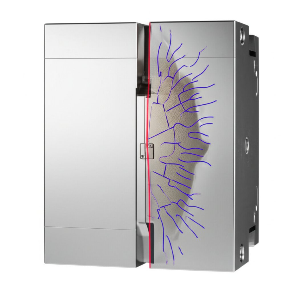
Na druhou stranu trhliny a smršťovací pórovitost jsou obvykle spojeny s fází chlazení a tuhnutí po zaplnění dutiny. Trhliny mohou být způsobeny tepelným napětím vzniklým nerovnoměrným chlazením, zejména u dílů s nepravidelnou tloušťkou stěn, nebo nadměrnou silou při vysouvání. Smršťovací pórovitost se projevuje jako vnitřní dutiny nebo povrchové prohlubně (tzv. útlaky) a vzniká tehdy, když není dostatek taveniny k vyrovnání zmenšení objemu během tuhnutí odlitku. K tomuto jevu často dochází u silnějších částí dílu, které se ochlazují pomaleji než okolní oblasti.
Pro řešení těchto problémů je nezbytná kombinace úprav návrhu, materiálu a procesu. Mezi klíčové kroky patří optimalizace geometrie dílu na rovnoměrnou tloušťku stěn, rovnoměrné předehřátí formy a úprava parametrů vstřikování. Následující tabulka shrnuje běžná řešení těchto tokových vad a vad tuhnutí.
| Vada | Hlavní příčiny | Klíčová řešení |
|---|---|---|
| Stopy toku & Studené spáry | Nízká teplota formy nebo taveniny; pomalá rychlost vstřikování; nesprávný návrh lití; špatné odvzdušnění. | Zvyšte teplotu formy a kovu; zvyšte rychlost a tlak vstřikování; optimalizujte velikost a umístění vtoků pro lepší tok; vylepšete odvzdušnění formy. |
| Trhliny | Nerovnoměrné chlazení nebo předehřátí; nestejnorodá tloušťka stěny; vysoké napětí při vyhazování; nesprávné složení slitiny. | Zajistěte rovnoměrné předehřátí formy; přepracujte díl pro konzistentní tloušťku stěny; optimalizujte umístění a sílu vyhazovacích kolíků; ověřte složení slitiny. |
| Smrštění (vtisky) | Nestejnorodá tloušťka stěny způsobující horká místa; nedostatečný vstřikovací tlak nebo doba držení; lokální přehřátí formy. | Přepracujte díl pro rovnoměrnou tloušťku; zvyšte vstřikovací tlak a dobu držení; optimalizujte chladicí kanály formy, aby se odstranila horká místa. |
Vady způsobené plynem, tlakem a kontaminací
Další kritickou skupinu vad lití pod tlakem způsobují faktory, které je obtížnější přímo pozorovat: zachycený plyn, nesprávné aplikovaní tlaku a cizí materiály v tavenině slitiny. Vady jako pórnost z plynu, puchýře, běhy a vměstky mohou vážně ohrozit strukturální pevnost a povrchovou úpravu odlitku. Tyto problémy často vznikají při přípravě kovu, stavu kokily nebo fyzice zaplňování dutiny za extrémního tlaku.
Plynová pórovitost je jednou z nejčastějších vad, která se projevuje malými dutinami nebo bublinami uzavřenými uvnitř kovu. Tyto dutiny oslabují součást a mohou představovat vážný problém u dílů, které musí být těsné vůči tlaku. Plyn může pocházet z několika zdrojů. Může se jednat o vodík uvolněný z taveniny slitiny hliníku samotného, vzduch, který se zachytí a promíchá s kovem kvůli turbulentnímu procesu plnění, nebo plyny vzniklé hořením separačního prostředku na formě, který shoří při kontaktu s horkým kovem. Bubliny na povrchu jsou povrchovým projevem tohoto jevu, kdy se plyn uvězněný těsně pod povrchem rozpíná a vytváří vyvýšený výběžek na odlitku.
Flash je vada související s tlakem a integrity formy. Projevuje se jako tenký, nežádoucí kovový lístek na okraji odlitku, tam kde se setkávají dvě poloviny formy. Flash vzniká, když roztavený kov unikne z dutiny pod vysokým tlakem. K tomu může dojít z několika důvodů: upínací síla stroje je příliš nízká na to, aby udržela formu uzavřenou, lití pod tlakem je příliš vysoké, povrch forem je opotřebovaný nebo poškozený, nebo je přítomný nečistoty bránící dokonalému uzavření formy.
Nakonec tzv. vměstky jsou jakékoli cizí materiály zachycené v odlitku. Může se jednat o kovové nebo nekovové částice, například oxidy z roztaveného kovu, nečistoty z tavící pece nebo nečistoty z recyklovaného materiálu. Vměstky vytvářejí místa koncentrace napětí uvnitř odlitku, která mohou vést k předčasnému selhání. Jejich prevence vyžaduje důsledné dodržování čistoty a manipulačních postupů během celého procesu tavení a lití.
Odstraňování problémů s plynatostí a bublinami
- Běžné příčiny: Rozpuštěný vodík v tavenině slitiny; vlhkost na ingotech nebo nástrojích; turbulence během vstřikování; nadměrné nebo nevhodné uvolňovací činidlo pro forma.
-
Účinné řešení:
- Použijte techniky odplyňování kovu k odstranění rozpuštěného vodíku před odléváním.
- Zajistěte, aby všechny kovové ingoty a nástroje byly před použitím zcela čisté a suché.
- Optimalizujte systém lití a přívodů tak, aby podporoval hladký, neturbulentní tok kovu do formy.
- Zajistěte, aby byly větrací kanály ve formě čisté a měly vhodnou velikost pro únik zachyceného vzduchu.
- Používejte vysoce kvalitní mazivo pro formu a aplikujte jej šetrně a rovnoměrně.
Odstraňování potíží s přelitím
- Běžné příčiny: Nedostatečná uzavírací síla stroje; nadměrný tlak vstřikování; opotřebované nebo poškozené dělící plochy formy; nečistoty na plochách formy.
-
Účinné řešení:
- Ověřte a zvyšte uzavírací sílu stroje, aby byla dostatečná pro plochu výrobku.
- Před každým cyklem vyčistěte dělící plochy formy.
- Snížete-li tlak vstřikování na nejnižší účinnou úroveň.
- Pravidelně provádějte údržbu formy, aby bylo možné opravit opotřebení nebo poškození čar rozdělení.
Vady způsobené interakcí formy a stroje
Fyzická a tepelná interakce mezi taveninou slitiny, ocelovou formou a samotným odlívacím strojem je častým zdrojem vad. Problémy, jako je pájení, tažení, tepelné trhliny a nesouosost dílů, nejsou způsobeny pouze kovem, ale stavem a seřízením výrobního zařízení. Tyto vady často ukazují na potřebu lepší údržby, úprav nástrojů nebo změn v nastavení a provozu formy a stroje.
Pájení nastává, když se roztavená slitina chemicky spojí nebo svaří s povrchem dutiny formy. To má za následek drsné plochy na odlitku a může způsobit poškození formy při vysouvání. Hlavními příčinami jsou eroze materiálu formy způsobená vysokými teplotami nebo přímým dopadem proudícího kovu, nesprávný obsah železa v hliníkové slitině nebo drsný povrch dutiny formy, který poskytuje kovu kotvu, za kterou se může zachytit.
Drhy a škrábance jsou rýhy nebo hluboké čáry na povrchu odlitku, vždy rovnoběžné se směrem vysouvání. Tento defekt jednoznačně signalizuje problém s vyjímáním dílu z formy. Obvykle je způsoben nedostatečným úhlem vyklopení ve tvaru dílu, drsným nebo poškozeným povrchem dutiny, který díl drží, nebo nesrovnanými vymrhacími kolíky, které díl vystrkují nerovnoměrně.
Teplotní trhliny, známé také jako tepelná únava, se projevují sítí jemných trhlinek na povrchu tvářecí formy, které se následně přenášejí na odlitky ve formě odpovídajícího vyvýšeného vzoru. Jedná se o dlouhodobou opotřebení způsobené neustálými a rychlými cykly ohřevu a chlazení, kterým forma podléhá. Nesouosost dílů je další mechanická závada, při které obě poloviny formy nejsou dokonale zarovnány, což má za následek viditelný posun nebo schod podél rozdělovací roviny dílu. K tomu často dochází kvůli opotřebovaným nebo nesprávným vodicím kolíkům ve formě nebo ve stroji.
Zabránění těmto vadám vyžaduje zaměření na kvalitu nástrojů a pečlivou údržbu. U kritických aplikací je důležité spolupracovat s dodavateli specializujícími se na vysoce kvalitní kovové komponenty, čímž se zdůrazňuje význam přesnosti od základů. Řešení často zahrnují jak preventivní opatření, tak nápravná opatření.
- Pájení: Aby se zabránilo pájení, je nezbytné zlepšit chlazení formy v problematických oblastech, vybrousit dutinu formy na hladký povrch a ověřit, že obsah železa v slitině je v doporučeném rozmezí (obvykle 0,8 % až 1,1 %). Použití vysoce kvalitního a správně aplikovaného separačního prostředku pro formu také poskytuje důležitou bariéru.
- Zatlačení: Řešením zatlačení je analýza dílu a návrhu formy. To může zahrnovat zvětšení vykružovacích úhlů, broušení stěn dutiny a zajištění vyváženého a správného fungování vymhacího systému.
- Teplotní trhliny: Ačkoli teplotní trhliny jsou při dlouhé výrobní sérii nevyhnutelné, jejich vznik lze oddálit správným předehřátím formy před spuštěním, vyhýbáním se nadměrným kolísáním teploty a používáním vysoce kvalitní nástrojové oceli.
- Neshodné díly: Tento problém vyžaduje mechanickou kontrolu formy a stroje. Řešením je obvykle odstranění závad na lití pod tlakem a výměna opotřebených nebo nesprávných centrovacích a upevňovacích čepů, aby se obnovila správná shoda.
Proaktivní strategie pro bezchybné odlévání
Efektivní řešení vad při tlakovém lití spočívá méně v reakci na jednotlivé problémy a více ve vytváření proaktivní strategie kontroly kvality. Hlavní příčiny většiny vad – ať už související s teplotou, tlakem, znečištěním nebo mechanickým opotřebením – jsou vzájemně propojeny. Změna provedená za účelem odstranění jednoho problému, například zvýšení rychlosti plnění kvůli odstranění studeného spáru, může neúmyslně způsobit jiný problém, jako je přelití. Proto je pro dosažení konzistentního úspěchu nezbytný celkový a systematický přístup.
Základem této strategie je pečlivá kontrola procesu a pravidelná údržba. To zahrnuje důsledné čištění forem, opatrné zacházení s výchozími materiály za účelem prevence kontaminace a pravidelnou kontrolu stroje i nástrojů na příznaky opotřebení. Dodržováním logického postupu odstraňování problémů, který začíná nejjednoduššími proměnnými, mohou obsluhy efektivněji řešit potíže a vyhnout se nákladným a zbytečným zásahům. Konečně výroba kvalitních odlitků bez vad je výsledkem kombinace robustního návrhu dílu, vysoce kvalitního nástroje a hlubokého porozumění parametrům procesu.
Nejčastější dotazy
1. Jaké jsou vady při tlakovém lití?
Běžné vady při tlakovém lití lze seskupit do kategorií. Mezi ně patří problémy s tokem a tuhnutím (stopy toku, studené spory, trhliny, smrštění), problémy s plynem a tlakem (plynové póry, bubliny, běhoun), problémy s kontaminací (vměstky) a vady způsobené interakcí formy/stroje (přivařování, tažení, tepelné trhliny, nesouosost dílů).
2. Jak zkontrolovat odlévací vady?
Hlavní metodou pro kontrolu odlévacích vad je důkladná vizuální prohlídka, která umožňuje identifikovat povrchové problémy, jako jsou trhliny, běžící hrany, stopy toku a úsady. Pro vnitřní vady, jako je pórnost způsobená plynem nebo smrštěním, mohou být nutné pokročilejší metody, jako je rentgenová prohlídka nebo destruktivní zkoušení, aby bylo možné posoudit vnitřní integritu součásti.
3. Co je to vada běžící hrany při tlakovém lití?
Běžící hrana je běžnou vadou, při které se na okraji odlitku vytvoří tenký nadbytečný kovový plát, obvykle podél dělící roviny, kde se poloviny formy setkávají. Vzniká tehdy, když roztavený kov unikne dutinou pod vysokým tlakem, často kvůli nedostatečné upínací síle, opotřebované formě nebo nečistotám na povrchu formy.
4. Jakých sedm odlévacích vad existuje?
I když existuje mnoho typů odlévacích vad, sedm nejčastějších jsou pórnost způsobená plynem, pórnost způsobená smrštěním, trhliny, běžící hrany (flash), studené spory, stopy toku a zazdění. Tyto vady zahrnují širokou škálu příčin, od problémů s teplotou kovu a obsahem plynu až po potíže s tlakem vstřikování a stavem formy.