 Küçük partiler, yüksek standartlar. Hızlı prototip hizmetimiz doğrulamayı daha hızlı ve kolay hale getirir —

Sac Metal Şekillendirme Kalıpları: Tasarım Hatalarından Kusursuz Parçalara
Sac Metal Şekillendirme Kalıplarını ve Üretimdeki Rolünü Anlamak
Düz bir metal parçasının nasıl bir araba kapı paneli, bir uçak parçası ya da akıllı telefonunuzun şık kasasına dönüştüğünü hiç merak ettiniz mi? Cevap, çoğu insanın asla görmediği hassas kalıplamada gizlidir— sac metal şekillendirme kalıpları . Bu özel araçlar, modern üretim süreçlerinin merkezinde yer alır ve ham maddeleri, günlük hayatımızı tanımlayan karmaşık şekillere sessizce dönüştürür.
Modern Metal Üretiminin Temeli
Temelde bir kalıp, metalin kontrollü kuvvet uygulaması yoluyla şekillendirilmesini, kesilmesini ve biçimlendirilmesini sağlar. Peki sac metal şekillendirme bağlamında kalıp yapımı nedir? Bu, aynı parçaları tam olarak belirlenmiş toleranslarla tekrar tekrar üretebilecek hassas araçların yaratılması sanatı ve bilimidir.
Şekillendirme kalıbı, malzemeyi yalnızca kesme işlemiyle değil, aynı zamanda sıkıştırma, gerilme veya her ikisini birlikte kullanarak deformasyon yoluyla yeniden şekillendiren özel bir kalıp türüdür. Sadece metal levhayı keserek ayıran kesme kalıplarının aksine, şekillendirme kalıpları malzemenin mekanik özelliklerinden yararlanarak düz levhayı bükme, germe ve çekme işlemlerine tabi tutarak üç boyutlu şekiller elde eder.
Levhadan şekillendirme, mevcut en verimli imalat yöntemlerinden biridir. Tek bir kalıp aracı, şaşırtıcı derecede tutarlılıkla binlerce—hatta milyonlarca—aynı parçayı üretebilir. Bu tekrarlanabilirlik, bu hassas aletleri otomotiv ve havacılık sektörlerinden tüketici elektroniği ve tıbbi cihazlara kadar geniş bir endüstri yelpazesi boyunca vazgeçilmez kılar.
Kalıplar Nasıl Düz Levhayı Hassas Parçalara Dönüştürür?
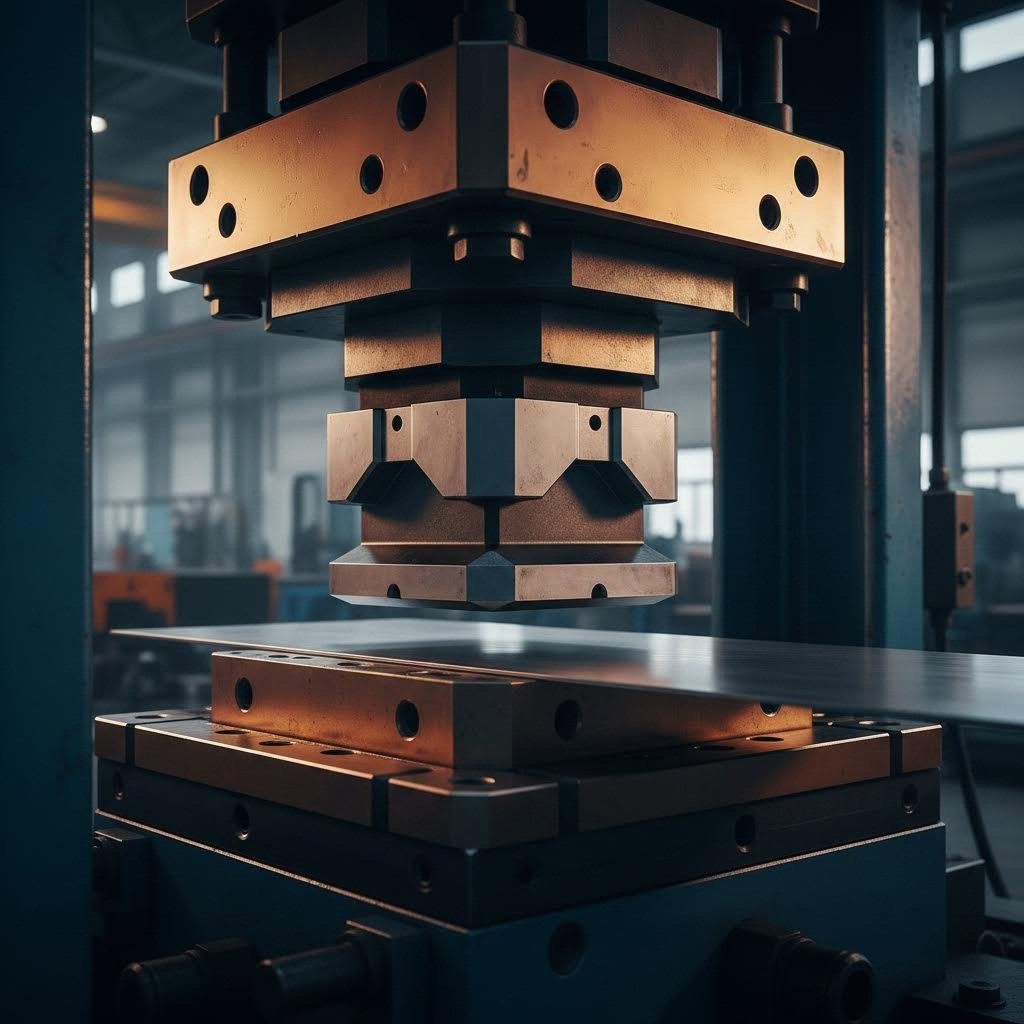
Dönüşüm süreci, birbirleriyle uyum içinde çalışan iki temel bileşenden oluşur: çakma (erkek bileşen) ve kalıp bloğu (dişi bileşen). Devasa kuvvet üretme kapasitesine sahip bir presin içine monte edildiklerinde bu elemanlar, elle yapılan yöntemlerle mümkün olmayan şekillerde metalin yeniden biçimlendirilmesini sağlar.
Mekanizma zarifçe basit olmakla birlikte dikkat çekici derecede hassastır. Pres aşağı doğru hareket ettiğinde çakma, sac metali kalıp boşluğuna veya kalıp çevresine iter. Metal şekillendirme işlemi, dikkatlice hesaplanan aşağıdaki faktörlere bağlıdır:
- Malzeme kalınlığı ve mekanik özellikleri
- Çakma ile kalıp yüzeyleri arasındaki açıklıklar
- Uygulanan kuvvet ve pres hızı
- Yağlama ve yüzey koşulları
- Belirli alaşımlar için sıcaklık dikkat edilmesi gereken faktörler
Kalıp formlarının özellikle ilgi çekici kılan yönü, malzemenin doğal davranışından yararlanmalarıdır. Bir metal parçasını büküldüğünde, bu parça orijinal şekline geri dönmek ister. Yetenekli kalıp tasarımcıları bu geri dönme (spring-back) fenomenini dikkate alarak, son parça istenen nihai geometrisine rahatça oturabilmesi için kalıplarını biraz fazla bükme veya fazla şekillendirme amacıyla tasarlarlar.
Kalıp türünün seçimi, parça kalitesinden üretim maliyetlerine kadar her şeyi doğrudan etkiler. Uyumsuz bir kalıp seçimi, kusurlu parçalara, aşırı hurda oranlarına ve tüm tedarik zincirlerine yayılan üretim gecikmelerine yol açabilir. Buna karşılık doğru kalıp çözümü—uygun şekilde tasarlanmış ve üretilmişse—optimal parça başı maliyetle tutarlı kalite sunar.
Bu kılavuz boyunca, farklı şekillendirme kalıplarının çeşitli imalat ihtiyaçlarına nasıl hizmet ettiğini, bunların üretiminde hangi malzemelerin ve yöntemlerin kullanıldığını ve belirli uygulamanız için doğru yaklaşımı nasıl seçeceğinizi öğreneceksiniz. Metal şekillendirmeyi ilk kez mi keşfediyorsunuz yoksa mevcut süreçlerinizi mi optimize etmeye çalışıyorsunuz, bu temel kavramları anlamanız, daha akıllı kalıp seçimleri yapmanızı sağlayacaktır.
Şekillendirme Kalıpları Türleri ve Sınıflandırmaları Konusunda Tam Kılavuz
Artık bu hassas araçların nasıl çalıştığını öğrendiğinize göre, bir sonraki mantıklı soru şu olur: Hangi kalıp türü imalat ihtiyaçlarınıza uygun? Mevcut çeşit kalıp ve presleme seçenekleri ilk bakışta oldukça karmaşık görünebilir. Ancak her kategori belirli üretim senaryolarına hizmet eder ve bu farklılıkları anlamak, kalite, hız ve maliyet dengesini göz önünde bulunduran bilinçli kalıp kararları vermenize yardımcı olacaktır.
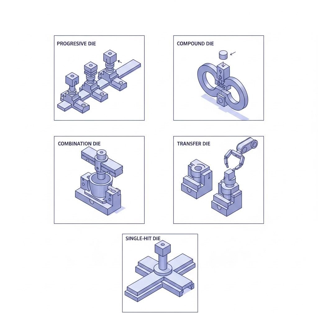
Kalıplar ve presleme işlemleri, belirli hacim gereksinimlerine, parça karmaşıklıklarına ve üretim ortamlarına göre beş ana sınıfa ayrılır. Her bir türün neyin onu benzersiz kıldığını inceleyelim.
Yüksek Hacimli Üretim İçin Progresif Kalıplar
Ham madde olarak bobin halindeki malzemenin bir uçtan girdiği ve neredeyse insan müdahalesi olmadan diğer uçtan tamamlanmış parçaların çıktığı bir üretim hattı hayal edin. İşte bu, ilerlemeli kalıpların gücüdür. Bu gelişmiş araçlar, malzeme her darbeyle pres içinde ilerlerken birden fazla istasyonda sıralı işlemler gerçekleştirir. her darbeyle malzeme bir "ilerleme" (genellikle soldan sağa) kadar ilerler.
İşlemin nasıl gerçekleştiğini aşağıda açıklıyoruz:
- Metal şerit, hassas hizalama sistemleriyle yönlendirilerek bobinden kalıba beslenir
- Her pres döngüsü malzemeyi bir "ilerleme" kadar ilerletir (genellikle soldan sağa)
- İlk istasyonlar, sonraki işlemler için doğru konumlandırmayı sağlamak amacıyla yönlendirme delikleri açar
- Sıralı istasyonlar kesme, delme, bükme veya şekillendirme işlemlerini gerçekleştirir
- Tamamlanmış parça, son istasyonda taşıyıcı şeritten ayrılarak çıkar
İlerlemeli kalıplar, hız ve tutarlılık en çok önemli olduğu yüksek hacimli uygulamalarda üstün performans gösterir. Bir kez kurulduktan sonra bu sistemler, malzeme akışını otomatik olarak yöneten besleyicilerle sürekli çalışabilir. Bunun karşılığı nedir? Daha yüksek başlangıç tasarım ve kalıp maliyetleri. Ancak uzun üretim süreçleri boyunca parça başına maliyet büyük ölçüde düşer; bu nedenle ilerlemeli kalıplar, otomotiv bileşenleri, elektronik konektörler ve tüketici ürünleri muhafazaları için tercih edilen çözüm haline gelir.
Bileşik ve Kombinasyon Kalıpları Açıklaması
Birden fazla işlemi sıralı istasyonlar yerine tek bir pres darbesiyle tamamlamanız gerekiyorsa ne olur? Bileşik kalıplar tam da bu yeteneği sunar. Bu metal şekillendirme kalıpları, genellikle kesme ve delme işlemlerini aynı istasyonda eş zamanlı olarak gerçekleştirir.
Bu iş akışını hayal edin: delme ucu aşağı iner ve tek bir birleşik hareketle delikler aşağı doğru delinirken dış profil yukarı doğru kesilir. Kesinti parçaları (slugs) kalıptan düşer ve bitmiş parça, atılma işlemi için boşluğa kalır. Bu eşzamanlı işlem, mükemmel düzlemsellik ve özellikler arasında sıkı toleranslara sahip parçalar üretir.
Bileşik kalıp ile dövme işleminin avantajları şunlardır:
- Delinen özellikler ile dış kenarlar arasındaki üstün boyutsal doğruluk
- Sıralı işlemlere kıyasla mükemmel parça düzlemselliği
- Daha basit geometriler için ilerlemeli kalıplara göre daha düşük kalıp maliyetleri
- Kavramdan üretim aşamasına kadar daha kısa teslim süreleri
Ancak bileşik kalıpların sınırlamaları da vardır. Parça çıkarma işlemi ek mekanizmalar gerektirir ve genellikle tek vuruşlu kalıplar olarak sınıflandırılırlar—ancak uygun atma sistemleriyle sürekli çalıştırılabilirler. Özellikler arası doğruluğun kritik olduğu, nispeten düz parçaların orta hacimli üretiminde en iyi sonuçları verirler.
Kombinasyon kalıpları, kesme ve şekillendirme işlemlerini tek bir araç içinde birleştiren hibrit bir yaklaşım benimser. Sadece kesme işlemlerine odaklanan saf bileşik kalıpların aksine, kombinasyon kalıpları bir parçanın çevresini keserken aynı anda bir büküm veya kabartma gibi şekillendirilmiş bir özelliği de oluşturabilir. Bu çok yönlülük, hem kesme hassasiyeti hem de biçimlendirilmiş geometri gerektiren parçalar için bu kalıpları değerli kılar.
Karmaşık Çok İstasyonlu İşlemler İçin Transfer Kalıpları
Bazı parçalar, ilerlemeli kalıp ile dövme işlemi için ya çok büyüktür ya da çok karmaşıktır. İş parçasının şeritten fiziksel olarak ayrılmalı ve istasyonlar arasında bağımsız olarak taşınması gerekiyorsa, transfer kalıpları tercih edilen çözüm haline gelir.
Transfer kalıp dövme işlemi, parçaları istasyondan istasyona taşımak için mekanik sistemler—parmaklar, tutucular veya raylar—kullanır. Her istasyon, serbest bırakılmış iş parçası üzerinde belirli işlemleri gerçekleştiren ayrı bir takıma sahiptir. Bu bağımsızlık şu avantajları sağlar:
- Derin çekmeler ve karmaşık üç boyutlu şekillendirme
- Parça döndürülmesi veya yeniden konumlandırılması gerektiren işlemler
- Şerit bağlantısını koruyamayan büyük parçalar
- İlerlemeli sistemlerde mümkün olmayan çok eksenli şekillendirme
Transfer sistemlerinin karmaşıklığı, diğer tip sac kesme kalıplarına kıyasla daha yüksek kalıp ve kurulum maliyetlerine neden olur. Bakım gereksinimleri de daha yoğundur çünkü hem kalıplar hem de transfer mekanizmaları düzenli olarak kontrol edilmelidir. Bununla birlikte, otomotiv yapısal parçaları veya ev aleti gövdesi gibi karmaşık bileşenlerin orta ila yüksek hacimli üretiminde transfer kalıpları, başka hiçbir yöntemle eşleşemeyen yetenekler sunar.
Daha Basit Uygulamalar İçin Tek Vuruşlu Kalıplar
Her imalat zorluğu karmaşık çok istasyonlu kalıplama gerektirmez. Tek vuruşlu kalıplar (tek istasyonlu kalıplar olarak da bilinir), her pres darbesiyle tek bir şekillendirme veya kesme işlemi gerçekleştirir. Basit yapıları, belirli üretim senaryolarında açık avantajlar sağlar.
Tek vuruşlu delme kalıpları aşağıdaki durumlarda üstün performans gösterir:
- Üretim hacmi düşük ila orta düzeydedir
- Delme pozisyonları veya şekilleri sık sık değişir
- Hızlı kalıp ayarlamaları gereklidir
- Bütçe kısıtlamaları, başlangıçta kalıp yatırımı üzerinde bir sınır oluşturur
- Parça tasarımları, geliştirme aşamalarında henüz evrim geçirmektedir
Bu durumun karşılığı, otomasyonun azalması ve üretim kapasitesinin düşmesidir. Her parça genellikle işlemler arasında elle yüklenmeyi ve konumlandırılmasını gerektirir. Ancak esneklik ve daha düşük üretim maliyetleri, tek vuruşlu kalıpların prototipleme, kısa seri üretim ve tasarım değişikliklerinin öngörüldüğü uygulamalar için ideal olmasını sağlar.
Kalıp Türleri Karşılaştırması (Özeti)
Kalıp türleri arasında seçim yapmak, birden fazla faktörü dengelemeyi gerektirir. Bu karşılaştırma tablosu, tüm beş kategori boyunca temel özellikleri özetlemektedir:
| Die türü | En Uygun Kullanım Alanı | Üretim Hacmi Aralığı | Karmaşıklık Seviyesi | Tipik Sektörler |
|---|---|---|---|---|
| Ilerleme damacı | Birbirini izleyen çoklu işlemler gerektiren karmaşık parçalar için | Yüksek hacimli üretim (100.000+ parça) | Yüksek | Otomotiv, Elektronik, Ev Aletleri |
| Bileşik kalıp | Aynı anda kesme ve delme işlemi gerektiren düz parçalar | Orta hacimli üretim (10.000–100.000 parça) | Orta derecede | Elektronik ürünleri, donanım ürünleri, hassas bileşenler |
| Kombine Kalıp | Tek bir darbede hem kesme hem de şekillendirme işlemi gerektiren parçalar | Orta hacimli üretim (10.000–100.000 parça) | Orta ile Yüksek | Otomotiv sektörü, tüketici ürünleri, endüstriyel ekipmanlar |
| Transfer Kalıp | Bağımsız istasyon operasyonları gerektiren büyük veya karmaşık parçalar | Orta ila yüksek hacim (50.000+ parça) | Yüksek | Otomotiv yapısal parçaları, ev aletleri, ağır ekipmanlar |
| Tek Vuruşlu Kalıp | Sık tasarım değişiklikleriyle birlikte basit operasyonlar | Düşük ila orta hacim (50.000'den az parça) | Bu | Prototipleme, iş atölyeleri, özel imalat |
Bu sınıflandırmaları anlamak, akıllı kalıp seçimleri için temel oluşturur. Ancak kalıp türü denklemin yalnızca bir parçasıdır. Bu kalıpların gerçekleştirdiği belirli şekillendirme operasyonları — ve bu operasyonları malzeme özelliklerinin nasıl etkilediği — parçalarınızın teknik şartnamelere uyup uymadığını ya da hurda kutusuna mı gideceğini belirler.
Şekillendirme Operasyonları ve Mekanik İlkeleri
Farklı kalıp türlerinin farklı üretim ihtiyaçlarına nasıl hizmet ettiğini gördünüz. Ancak işler burada gerçekten ilginç hale geliyor: Bu aletlerin gerçekleştirdiği özel metal şekillendirme işlemleri, nihai parçalarınızın kesin spesifikasyonları karşılayıp karşılamadığını belirler ya da yetersiz kalmasına neden olur. Her şekillendirme işlemi benzersiz mekanik prensiplerden yararlanır ve bunları anlamak, sorunlar maliyetli hâle gelmeden önce önceden tahmin etmenizi sağlar.
The şekillendirme imalat süreci malzeme eklenmeden veya çıkarılmadan metalin kalıcı olarak yeniden şekillendirilmesini içerir. Kesme işlemlerinin stok malzemeyi keserek ayırmasıyla karşılaştırıldığında, metal şekillendirme işlemleri kontrollü plastik deformasyona dayanır; yani malzeme akma sınırını aşacak şekilde itilir ve yeni şeklini korur. En kritik teknikleri ve başarılarını etkileyen parametreleri inceleyelim.
Bükme İşlemleri ve Geri Yaylanma Kontrolü
Bükme, sac metal işlemenin belki de en yaygın şekillendirme işlemidir. Basit görünüyor, değil mi? Metal parçayı bir açıda katlayın ve işiniz bitiyor. Gerçek şu ki, hassas bükme açılarını tutarlı bir şekilde elde etmek için üç farklı bükme yöntemiyle ilgili bilgi sahibi olmak gerekir—her birinin kendine özgü özellikleri vardır.
Hava Bükümü hava bükme yöntemi en büyük esnekliği sunar. Burada punch (çıkartma), malzemeyi tam olarak dibe oturtmadan V şeklindeki kalıp açıklığına doğru iter. Sonuçta elde edilen açı tamamen punch derinliğine bağlıdır; yani yalnızca strok derinliğini ayarlayarak tek bir kalıpla birden fazla açı üretilebilir. Ancak hava bükmede metal şekillendirme sırasında tam olarak sınırlandırılmadığından en yüksek geri yayılma (spring-back) oluşur.
Altta Tam Bitiş (bazen alttan bükme olarak da adlandırılır) malzemeyi tamamen kalıp boşluğuna zorlar. Punch ve kalıp yüzeyleri, bükme bölgesinde iş parçasıyla tam olarak temas eder; bu da daha tutarlı açılar ve azaltılmış geri yayılma ile sonuçlanır. Bunun karşılığı nedir? Her belirli açı için ayrı bir takım takımı gereklidir.
Köşeleme büküm şeyleri bir adım öteye taşır. Bu metal şekillendirme ve damgalama tekniği, malzemeyi büküm bölgesinde plastik olarak deforme etmek için aşırı basınç uygular—genellikle alttan dayama (bottoming) işlemine kıyasla beş ila sekiz kat daha fazla. Sonuç? Neredeyse sıfır geri yaylanma ve keskin büküm yarıçapları. Damgalama işlemi, sıkı açı toleranslarının vazgeçilmez olduğu durumlarda kritik öneme sahiptir.
Geri yaylanma, tüm bükme işlemlerinde kritik mühendislik unsuru olarak kalmaya devam eder. Basınç kaldırıldığında metal, orijinal düz haline geri dönmeye çalışır. Geri yaylanmayı etkileyen temel parametreler şunlardır:
- Malzeme akma mukavemeti: Daha yüksek mukavemetli malzemeler daha agresif şekilde eski hâline döner
- Bükme yarıçapının kalınlığa oranı: Daha dar yarıçaplar geri yaylanmayı azaltır ancak çatlama riskini artırır
- Büküm açısı: Daha büyük açılar genellikle daha fazla geri yaylanmaya neden olur
- Tane Yönü: Tane yönüne dik bükme ile tane yönüne paralel bükme sonuçları önemli ölçüde farklılık gösterir
- Malzeme Kalınlığı: Daha kalın malzeme genellikle oransal olarak daha az geri yaylanma gösterir
Deneyimli kalıp tasarımcıları, fazla bükerek bu durumu telafi eder—hedef açıların ötesinde açılar oluşturmak üzere kalıbı mühendislikle tasarlayarak parça soğuduktan sonra doğru geometriye oturmasını sağlarlar. Bu telafi miktarının doğru belirlenmesi genellikle deneme çalışması ve yinelemeli ayarlamalar gerektirir; özellikle yüksek mukavemetli çelikler veya egzotik alaşımlarla çalışıldığında bu durum daha belirgindir.
Çekme, Kenar Oyma ve Kabartma Mekaniği
Bükme işlemi açısal özellikler oluştururken, çekme işlemleri derinlik üretir. Düz bir diskten pürüzsüz bir kupa oluşturmayı hayal edin—bu, metal şekillendirme sürecinin çekme olarak adlandırılan temelidir. Buna göre İmalatçı , çekme işlemi, neredeyse aynı toplam yüzey alanına sahip alternatif bir şekle sahip bir kap içine mevcut yüzey alanının yer değiştirmesi olarak tanımlanabilir.
Çekme işleminin benzersiz olmasını sağlayan şey şudur: saf gerilimden ziyade kontrollü bir metal akışı gerektirir. Şekillendirme plakası (çekme yastığı veya bağlayıcı olarak da bilinir), malzemenin kalıp boşluğuna nasıl beslendiğini kontrol etmek için baskı uygular. Çok az baskı buruşmalara neden olur; çok fazla baskı ise akışı kısıtlayarak yırtılmaya yol açar. İdeal baskıyı bulmak kritik öneme sahiptir.
Çekme işlemlerini etkileyen temel parametreler şunlardır:
- Çekim oranı: Ham madde çapı ile bitmiş parça çapı arasındaki ilişki
- Şekillendirme plakası basıncı: Buruşma önleme ile malzeme akışını kısıtlama arasında dengenin sağlanması gerekir
- Kalıp yarıçapı: Daha büyük yarıçaplar malzeme akışını kolaylaştırır ancak özellik tanımlamasını zayıflatabilir
- Yağlama: Metalin boşluğa sorunsuz şekilde girmesini sağlayan sürtünmeyi azaltır
- Çekme hızı: Daha yüksek hızlar, malzemenin davranışını etkileyebilecek ısı oluşturabilir
- Hava Tahliyesi: Hataları ve sökme zorluklarını önlemek için hapsedilen hava dışarıya kaçabilmelidir
Kenar Oyma parçanın çevresi boyunca veya deliklerin etrafında içe ya da dışa doğru bükülmüş kenarlar oluşturur. Bu şekillendirme işlemi, kenarları güçlendirir, bağlantı noktaları oluşturur veya birleştirme işlemlerine hazırlık sağlar. İşlemin mekaniği, özellikle eğri kenarların flanşlanması gibi durumlarda metalin gerilmesi veya sıkışması gereken malzeme akışı dikkate alınarak bükme prensiplerini birleştirir.
Çizgi malzemenin delinmeden yükseltilmiş veya çökertilmiş özellikler üretir. Örneğin, ev aleti panellerine bastırılan logolar ya da yapısal bileşenlere oluşturulan takviye kabartmaları düşünülebilir. Bu şekillendirme işlemi, parçanın genel düzlemini korurken yüzeysel, yerel deformasyon oluşturmak için eşleşen erkek ve dişi kalıp yüzeylerini kullanır.
Kabartma kalitesini etkileyen parametreler şunlardır:
- Özellik derinliği: Daha derin kabartmalar daha fazla kuvvet gerektirir ve yırtılma riski yaratır
- Duvar çekme açıları: Hafif koniklikler malzeme akışını kolaylaştırır ve kalıbın ayrılmasını sağlar
- Köşe Yarıçapları: Keskin iç köşeler gerilimi yoğunlaştırır ve arızaya neden olabilir
- Malzeme sünekliği: Daha şekillendirilebilir alaşımlar, daha derin ve daha karmaşık kabartma özelliklerini kabul eder
Malzeme kalınlığı ve türü, tüm bu işlemler boyunca işlem seçimi üzerinde temel düzeyde etki eder. Daha ince sac levhalar bükülme ve çekme işlemlerine daha kolay uyum sağlar ancak yapısal rijitlik açısından daha az dayanıklılık sunar. Daha kalın malzemelerin çatlama riskini önlemek için daha büyük kuvvetler ve daha geniş yarıçaplar gerektirir. Benzer şekilde malzemenin bileşimi de önemlidir; alüminyumun daha yüksek geri yaylanma (spring-back) özelliği, yumuşak çelikle karşılaştırıldığında farklı telafi stratejileri gerektirirken, paslanmaz çeliğin işlenme sırasında sertleşmesi (work-hardening), derin çekme sırasında benzersiz zorluklar yaratır.
Bu mekanik ilkeleri anlayarak, önerilen kalıp tasarımının sizin ihtiyaç duyduğunuz sonuçları gerçekten sağlayıp sağlamayacağını değerlendirmeniz için gerekli temeli oluşturursunuz. Ancak malzeme seçimi, karmaşıklığı bir katman daha artırır: Farklı metaller şekillendirme kuvvetleri altında farklı davranışlar gösterir ve belirli bir malzeme için kalıplamanızı ona özel olarak uyarlamak, tutarlı kalite elde etmek açısından hayati öneme sahiptir.
Farklı Sac Metal Türleri İçin Malzemeye Özel Gereksinimler
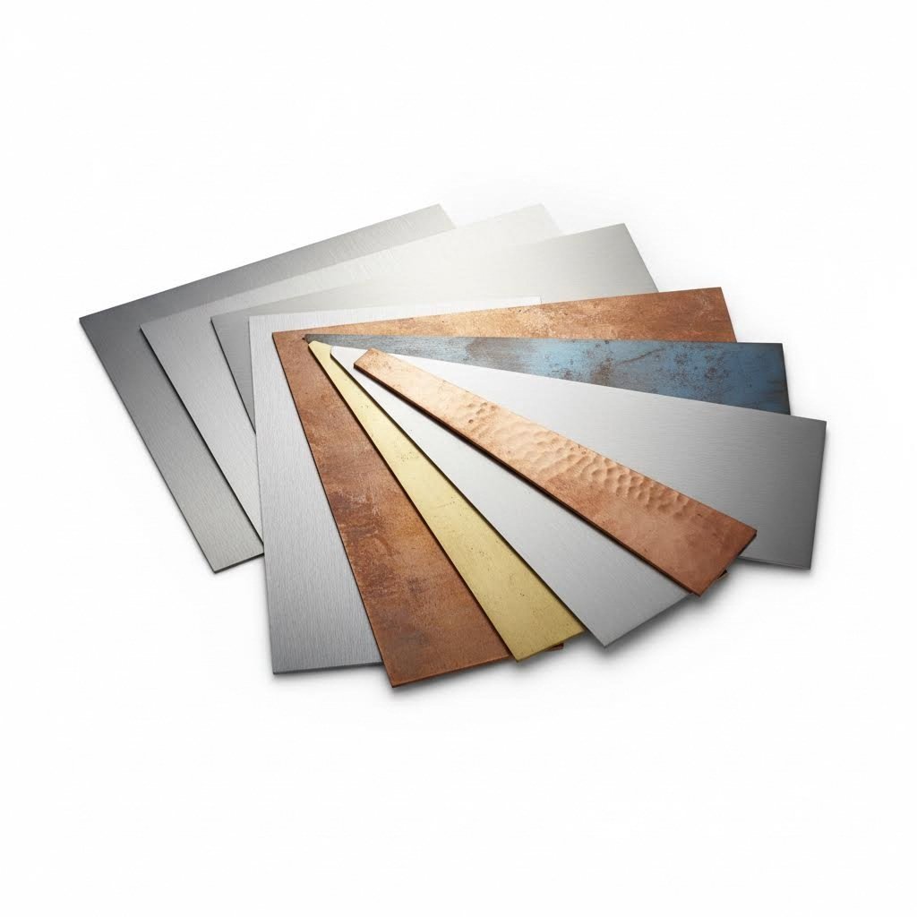
Yani kalıp tipinizi seçtiniz ve şekillendirme mekaniğini anladınız—ancak üretim sürecinizi başarıya ya da başarısızlığa götürebilecek şu soru aklınıza gelmiş mi? Belirli malzemeniz her şeyi nasıl değiştiriyor? Gerçek şu ki, presleme için kullanılan saclı metal tek boyutlu bir kategori değildir. Her alaşım grubu, kalıp tasarımı, boşluk hesaplamaları ve süreç parametreleri üzerinde doğrudan etki yaratan benzersiz davranışlar sergiler.
Bunu şöyle düşünün: Alüminyum şekillendirmek, paslanmaz çelik ile çalışmakla tamamen farklı bir his verir. İlgili kuvvetler, malzemenin ne kadar geri döndüğü ve takımınızın ne kadar hızlı aşınacağı gibi unsurlar büyük ölçüde değişir. Bu malzemeye özel detayları doğru şekilde belirlemek, başarılı üretim partilerini başarısızlıkla sonuçlanan hurda yığınlarından ayırır.
Alüminyum ve Hafif Alaşımlarla İlgili Dikkat Edilmesi Gereken Hususlar
Alüminyumun sac metal presleme işlemlerindeki popülaritesi, özellikle ağırlık azaltımının önemli olduğu otomotiv ve havacılık uygulamalarında giderek artmaya devam ediyor. Ancak alüminyumun "şekillendirilmesi kolay" olarak bilinen imajı sizi yanıltmasın. Bu hafif ağırlıklı metal kendi kendine özgü zorlukları da beraberinde getirir.
İyi haber mi? Alüminyum, çelikle karşılaştırıldığında önemli ölçüde daha düşük şekillendirme kuvvetleri gerektirir. Buna göre sektör üreticilerinden alınan kalıp teknik özellikleri gereğince, alüminyum için delme kuvveti hesaplanırken kesme mukavemeti katsayısı yalnızca 20-25 kg/mm² alınır; bunun karşılığı yumuşak çelikte 40-50 kg/mm²’dir. Bu durum, alüminyum alaşımlarıyla çalışırken pres kapasitenizin daha verimli kullanılmasını sağlar.
Zorlu kısım mı? Geri yaylanma (spring-back). Alüminyumun daha düşük elastisite modülü, parçaların şekillendirmeden sonra orijinal şekillerine daha güçlü bir şekilde dönme eğilimi göstermesine neden olur. Alüminyum bileşenlerde sıkı açı toleransları elde etmek için, geri yaylanmayı neredeyse tamamen ortadan kaldırmak amacıyla çok yüksek basınç uygulanan 'körleme (coining)' işlemi hayati öneme sahiptir.
Alüminyum için kalıp açıklığı gereksinimleri de önemli ölçüde farklılık gösterir. Alüminyum için önerilen açıklık yüzdesi, malzeme kalınlığının %12–%16'sı arasındadır; bu değer çelikten daha dar, ancak bakırdan daha geniştir. Bu durum, belirli açıklık değerlerine karşılık gelir:
- 1,0 mm alüminyum: Toplam açıklık 0,12–0,16 mm
- 2,0 mm alüminyum: Toplam açıklık 0,24–0,30 mm
- 3,0 mm alüminyum: Toplam açıklık 0,35–0,45 mm
Yüzey yapışması (galling), alüminyuma özgü başka bir konudur. Malzemenin kesme takımlarının yüzeylerine yapışma eğilimi, kalıp kaplamalarına, yağlamaya ve yüzey pürüzlülüğüne dikkatli yaklaşımı gerektirir. Uygun önlemler alınmadığı takdirde alüminyum, delici yüzeylerine kendini kaynaklayabilir; bu da yüzey kusurlarına ve takım aşınmasının hızlanmasına neden olur.
Çelik ve Paslanmaz Çelik Şekillendirme Gereksinimleri
Çelik, preslenmiş sac metal bileşenler için hâlâ en yaygın kullanılan malzemedir; ancak bu kategori, yumuşak düşük karbonlu türlerden yüksek mukavemetli yapısal alaşımlara kadar çok geniş bir yelpazeyi kapsar. Her alt küme, özel olarak tasarlanmış kalıp özelliklerini gerektirir.
Yumuşak çelik, en hoşgörülü şekillendirme özelliklerini sunar. Orta düzeyde mukavemet ve iyi sünekliğe sahip olması nedeniyle, aşırı geri yayılma veya çatlama olmadan agresif şekillendirme işlemlerini kabul eder. Yumuşak çelik için tasarlanan çelik kalıp pulları genellikle malzeme kalınlığının %16-20'si kadar boşluk kullanır; bu da şunu ifade eder:
- 1,0 mm yumuşak çelik: Toplam boşluk 0,16-0,20 mm
- 2,0 mm yumuşak çelik: Toplam boşluk 0,34-0,40 mm
- 3,0 mm yumuşak çelik: Toplam boşluk 0,50-0,60 mm
Paslanmaz çelik denklemi kökten değiştirir. Daha yüksek çekme dayanımına sahip olması—delme kuvveti hesaplamalarında 60-70 kg/mm² kesme dayanımı gerektirmesi—daha güçlü pres kapasitesi ve kalıp takımı gerektirir. Ancak daha büyük zorluk nedir? İşlenebilirlik sertleşmesi (work hardening). Paslanmaz çelik, şekillendirildikçe giderek daha sert hâle gelir; bu da şunları gerektirir:
- İlerleyici işlemler, her istasyonda artan sertliği dikkate almalıdır
- Derin çekmeler, sünekliği yeniden kazandırmak için ara tavlama işlemi gerektirebilir
- Daha keskin delici kenarlar ve daha dar boşluklar, işlenebilirlik sertleşmesi etkilerini en aza indirmeye yardımcı olur
Paslanmaz çelik için boşluk gereksinimleri, kalınlığın %18–24’ü oranında düşük karbonlu çeliğe kıyasla daha yüksektir. Metal presleme tasarım kılavuzlarına göre, paslanmaz çelik alaşımlarında delik açılırken minimum çap, malzemenin kalınlığının en az iki katı genişliğinde olmalıdır—daha düşük mukavemetli malzemeler için bu oran yalnızca 1,2 katıdır.
Yüksek mukavemetli düşük alaşımlı (HSLA) çelikler ve gelişmiş yüksek mukavemetli çelikler (AHSS), bu hususları daha da ileriye taşır. Bu malzemelerin üstün dayanım/ağırlık oranları, azaltılmış şekillendirilebilirlik, artmış geri yaylanma (spring-back) ve hızlandırılmış kalıp aşınması ile birlikte gelir. Bu malzemeler için sac metal presleme kalıpları, genellikle yüksek aşınma bölgelerinde premium kalıp çelikleri veya karbür kaplamalı takımlar gerektirir.
Bakır ve Pirinç Şekillendirme Özellikleri
Bakır ve alaşımları—including pirinç ve bronz—harika şekillendirilebilirlik sunarken aynı zamanda benzersiz zorluklar da beraberinde getirir. Bu malzemeler, iletkenlikleri veya görünüşleri önemli olduğu elektriksel bileşenler, dekoratif donanımlar ve hassas ölçüm aletleri gibi uygulamalarda tercih edilir.
Bakır, yaygın saclı metaller arasında en dar kalıp açıklıklarını gerektirir; tipik olarak kalınlığın %10–14’ü kadardır. Bu, aşağıdaki açıklık değerlerine karşılık gelir:
- 1,0 mm bakır: toplam açıklık 0,10–0,14 mm
- 2,0 mm bakır: toplam açıklık 0,20–0,25 mm
- 3,0 mm bakır: toplam açıklık 0,30–0,40 mm
Daha dar açıklıklar neden gerekir? Bakırın olağanüstü sünekliği, punch ile kalıp arasındaki boşluklara akmasına izin verir; açıklıklar çok gevşek ayarlanırsa aşırı kenar döküntüsü (bur) oluşur. Bunun ters yüzü ise bakırın yumuşaklığından kaynaklanan minimum kalıp aşınmasıdır; bakır işleyen takımlar, daha sert malzemelerle çalışan takımlara kıyasla genellikle daha uzun ömürlüdür.
Pirinç—tipik olarak bir bakır-çinko alaşımıdır—benzer şekilde davranır ancak biraz daha yüksek mukavemet gösterir. Şekillendirmeden sonra mükemmel işlenebilirlik sunar; bu nedenle ikincil işlemler gerektiren parçalar için popülerdir. Her iki malzeme de bakırın yapışma eğilimini (galling) paylaşır; bu nedenle yağlama ve takım yüzey koşullarına dikkat edilmesi gerekir.
Kalıp tasarımı için Malzeme Özellikleri Karşılaştırması
Sac metal pres kalıpları belirtirken, malzeme özelliklerinin kalıp parametreleriyle nasıl etkileşime girdiğini anlamak esastır. Bu karşılaştırma tablosu kritik farkları özetlemektedir:
| Malzeme Türü | Tipik Kalınlık Aralığı | Göreli Şekillendirme Kuvveti | Esrime Eğilimi | Kalıp Aşınması Hususları |
|---|---|---|---|---|
| Alüminyum Alaşımları | 0,5 mm – 4,0 mm | Düşük (20–25 kg/mm² kayma mukavemeti) | Yüksek – aşırı bükme telafisi gerektirir | Orta düzey – yapışma riski nedeniyle kaplamalar/yağlama gereklidir |
| Hafif Çelik | 0,5 mm - 6,0 mm | Orta (40–50 kg/mm² kayma mukavemeti) | Orta düzey – tahmin edilebilir telafi | Orta ila Yüksek – standart takım çelikleri yeterlidir |
| Paslanmaz çelik | 0,5 mm – 4,0 mm | Yüksek (60–70 kg/mm² kayma mukavemeti) | Orta ila Yüksek – iş sertleşmesi bileşenleri sorunlara neden olur | Yüksek – yüksek kaliteli takım çelikleri önerilir |
| Bakır | 0,3 mm – 3,0 mm | Düşük (15–20 kg/mm² kesme mukavemeti) | Düşük – malzeme son şekle kolayca şekillendirilebilir | Düşük – yumuşak malzeme aşınmayı en aza indirir |
| Pirinç | 0,3 mm – 3,0 mm | Düşük ile Orta | Düşük ile Orta | Düşük ila Orta – bakır ile benzer davranış gösterir |
Kalınlık aralıkları özel dikkat gerektirir. Daha ince malzemeler, kenar kalitesini korumak için daha dar yüzde boşluk oranları gerektirirken, daha kalın levhalar orantılı olarak daha büyük mutlak boşluklar gerektirir. Bir malzeme kategorisinin üst kalınlık sınırlarına yaklaşıldığında, çatlama önlenmesi için şekillendirme yarıçaplarının artırılması gerekir — bu özellikle paslanmaz çelik ve yüksek mukavemetli alaşımlar için kritik önem taşır.
Malzeme seçimi izole bir süreç değildir. Seçiminiz, delici ve kalıp imalatında kullanılan takım çeliklerinden tasarımın içine yerleştirilen boşluk değerlerine kadar, kalıp bileşenlerinin teknik özelliklerini doğrudan etkiler. Bu ilişkileri anlayarak, presle üretilen sac metal parçalarınızın belirtimlere uygun olarak çıkmasını ve pahalı hurda olarak sona ermemesini sağlayabilirsiniz.
Kalıp Tasarım Mühendisliği ve Bileşen Temelleri
Şekillendirme işlemlerini ve malzeme gereksinimlerini anlıyorsunuz—ancak işte burada teori gerçeklikle buluşur: kalıp tasarımı mühendisliği. Bu, hassas hesaplamaların, bileşen seçimlerinin ve doğrulama yöntemlerinin, kalıplarınızın kusursuz parçalar mı yoksa hayal kırıklığına uğratan hurda ürünler mi ürettiğini belirlediği aşamadır. Şaşırtıcı bir şekilde, birçok kaynak bu kritik ayrıntıları göz ardı eder. Değiştirelim bunu.
Başarılı kalıp imalatı, birbirleriyle bağlantılı üç temel unsuru ustalıkla yönetmeyi gerektirir: malzemeniz ve işleminize uygun boşluk (clearance) spesifikasyonları, üretim yüklerine dayanacak şekilde tasarlanmış bileşenler ve sorunları pahalıya mal olmalarından önce tespit eden doğrulama yöntemleri. Bu temel prensipleri anlamak, sadece kalıpları kullanan birinden, onları akıllıca belirten birine dönüşmenizi sağlar.
Kritik Boşluklar ve Tolerans Spesifikasyonları
Malzeme bölümündeki bu boşluk oranlarını hatırlıyor musunuz? Şimdi bunları uygulama zamanı geldi. MISUMI'nin mühendislik kılavuzlarına göre, boşluk, kesme işlemi sırasında malzemeyi kesmek ve temiz delikler oluşturmak için punch (delici) ile die (kalıp) kesim kenarları arasında gereken optimal mesafedir.
Gerçek boşluk değerlerini hesaplamak için temel formül şu şekildedir:
Boşluk (her bir tarafta) = Malzeme Kalınlığı × Önerilen Boşluk Oranı
"Her bir tarafta" ifadesi son derece önemlidir. Şartnamelerde %10 boşluk isteniyorsa, bu %10 oranı punch'ın her iki yanında da bulunmalıdır; yani die açıklığı toplamda punch çapından %20 daha büyüktür. Bu ilişkiyi yanlış anlamak, kalıp takımları alanında yapılan en yaygın hatalardan biridir.
Doğru boşluk oranını belirleyen faktörler nelerdir?
- Malzemenin sertliği ve çekme dayanımı: Daha sert ve daha yüksek dayanıma sahip malzemeler için daha büyük boşluk gerekir—örneğin yüksek dayanımlı çelikler için tipik olarak %15–25 aralığı, yumuşak alüminyum için ise %10–12 aralığı önerilir.
- İş Parçası Kalınlığı: Daha kalın malzeme, yüzde ilişkileri korurken orantılı olarak daha büyük mutlak boşluklar gerektirir
- Kenar kalite gereksinimleri: Daha dar boşluklar, kesim kenarlarını daha temiz hâle getirir ancak takım aşınmasını hızlandırır
- Takım ömrü beklentileri: Hafifçe daha büyük boşluklar kullanmak (%%11-20), takım üzerindeki gerilimi önemli ölçüde azaltabilir ve işletme ömrünü uzatabilir
Uygun boşluk, estetik bir sonuç sağlar: iş parçasının üst ve alt yüzeyindeki tane sınırı kırılma düzlemlerini hizalar ve kesim kenarlarında temiz bir çatlamaya neden olur. Boşluk çok dar ayarlandığında punta daha fazla zorlanır—fazla ısı üretir ve aşınmayı hızlandırır. Boşluk çok geniş olduğunda ise malzeme boşluğa akarak kenar böğürtlenleri (burrs) oluşturur; bu da maliyetli ikincil bitirme işlemlerini gerekli kılar.
Yarıçap özellikleri, metal pres kalıbı tasarımı için başka bir boyut ekler. Eğme yarıçapları, şekillendirilebilirlik ile geri yaylanma kontrolü arasında dengede olmalıdır. Genel kural nedir? İç eğme yarıçapı, yumuşak çelik gibi sünek malzemeler için en az malzeme kalınlığına eşit olmalı; daha az şekillendirilebilir alaşımlar için ise bu değer malzeme kalınlığının 1,5–2 katı olmalıdır. Bu asgari değerler ihlal edilirse, eğme hatlarında çatlama riski ortaya çıkar.
Tolerans birikimi muhtemelen en zor mühendislik zorluğudur. Her bir kalıp bileşeni kendi toleransına sahiptir: punta boyutları, kalıp boşluğu boyutları, yön verici pim yerleştirilmesi, plaka düzgünlüğü. Bu bireysel toleranslar birleşerek toplanır. ±0,05 mm parçanın doğruluğu gerektiren pres uygulamaları için kullanılan bir kalıp seti, son belirtimden önemli ölçüde daha sıkı bireysel bileşen toleransları gerektirir.
Temel Kalıp Bileşenleri ve İşlevleri
Pres işlemi için kalıp setleri, birbirleriyle uyum içinde çalışan özel bileşenlerden oluşur. Her bir bileşenin ne işe yaradığını ve neden önemli olduğunu anlamak, kalıplama kalitesini değerlendirmenize ve sorunlar ortaya çıktığında bunları gidermenize yardımcı olur. Moeller Precision Tool'ün mühendislik kaynaklarına göre, karşılaşacağınız temel kalıp bileşenleri şunlardır:
- Kalıp Tabanı (Kalıp Plakaları): Tüm diğer bileşenlerin monte edildiği temel yapıdır. Bu çelik veya alüminyum plakalar, üst ve alt kalıp yarısının hizasını koruyarak rijit bir destek sağlar. Kaliteli bir kalıp tabanı yapısı, genel kalıplama doğruluğunu ve ömrünü belirler.
- Kılavuz Pimleri ve Burçlar: Bu hassas elemanlar, üst ve alt kalıp plakalarını 0,0001 inç (on binde bir inç) doğrulukla hizalar. Toplu yataklı yönlendirme pimleri, ayrılmalarının kolaylığı nedeniyle sektör standardı haline gelmiştir; buna karşılık sürtünmeli pimler, belirli uygulamalarda doğru yönlendirme sağlar.
- Zımbalar: Metal levhayı gerçekte sıkıştırıp şekillendiren erkek kalıp parçaları. Yuvarlak, oval, kare, dikdörtgen ve özel şekillerde temin edilebilen bu delme uçları, tutucular içinde sabitlenir ve burun geometrisine bağlı olarak ya delik açar ya da şekillendirilmiş özellikler oluşturur.
- Kalıp Düğmeleri: Delme uçlarının dişi eşleri olan bu parçalar, delme uçlarının çalıştığı kesme kenarını sağlar. Kalıp düğmeleri, malzemenin kalınlığının %5–%10’u kadar delme ucunun boyutlarından daha büyük bir ölçüde dışa kaydırılır; bu "kalıp kırılması", kesmenin gerçekleştiği boşluk alanını oluşturur.
- Sökücüler: İş parçasını düz tutan ve şekillendirmeden sonra delme ucundan ayıran bileşenlerdir. Etkili ayırma sağlanmadığı takdirde parça delme ucuna yapışabilir ve tıkanıklık veya hasara neden olabilir. Mekanik ve poliüretan ayırıcılar her biri kendine özgü avantajlar sunar.
- Basınç Yastıkları (Levha Tutucuları): Malzemenin kalıp boşluklarına akışını kontrol etmek amacıyla çekme işlemlerinde kullanılan bu elemanlar, yaylı veya azotla çalışan sistemlerle çalışır. Bu sistemler, şekillendirme sırasında metalin kontrollü hareketini sağlarken buruşmaları önler.
- Kalıp Yayları: Sayfaları dönüşüm sırasında yerinde tutmak için gerekli kuvveti sağlayan helis şeklinde, yüksek kuvvetli sıkıştırma yayları. Mekanik tel bobin yayları ve azot gaz yayları farklı kuvvet ve alan gereksinimlerini karşılar.
- Kalıp Tutucular: Delici uçları, düğmeleri ve diğer kesme bileşenlerini konumlarında sabitlemek amacıyla kalıp plakalarına monte edilen tutuculardır. Top kilidi, omuzlu ve gerilebilir tipler farklı takımlama yapılarına ve bakım ihtiyaçlarına uyum sağlar.
Her bileşen kategorisi, belirli uygulamalar için özelleştirme seçenekleri sunar. Bu unsurların —malzemeleri, toleransları ve yapılandırmaları— birbiriyle etkileşimi, kalıp takımlamanızın tutarlı kalite mi yoksa sürekli sorun mu yaratacağını belirler.
CAE Simülasyonunun Kalıp Tasarımı Doğrulamasını Nasıl Dönüştürdüğü
Daha önce kalıp tasarımcılarını rahatsız eden bir soru şuydu: 'Bu takımlama gerçekten işe yarayacak mı?' Geleneksel olarak, cevap ancak pahalı kalıplar işlendikten ve deneme parçaları üretildikten sonra alınıyordu. Sorunlar, tekrar işleme, gecikmeler ve bütçe aşımına yol açıyordu.
Bilgisayar destekli mühendislik (CAE), bu denklemi temelden değiştirmiştir. Göre Engineering.com'un simülasyon teknolojisiyle ilgili kapsama alanı , mühendisler artık herhangi bir fiziksel kalıp işlenmeden önce sanal simülasyon yoluyla kalıp tasarımlarını doğrulayabilmektedir—bu da geliştirme süresini önemli ölçüde kısaltırken doğruluğu artırır.
PAM-STAMP gibi modern sac şekillendirme simülasyon yazılımları, ilerleyici, taşıma ve hattı sac metal kalıpları için uçtan uca doğrulama yetenekleri sunar. Bu teknoloji, mühendislere şu imkânları sağlar:
- Parçaların şekillendirme sırasında yırtılıp yırtılmayacağını, uzayıp uzamayacağını veya buruşup buruşmayacağını tahmin etmek
- Fiziksel kalıplar oluşturulmadan önce aşırı incelme alanlarını belirlemek
- Boşluk tutucu basınçlarını ve çekme çubuğu yapılarını sanal ortamda optimize etmek
- Dijital yinelemeler aracılığıyla geri yayılma telafi stratejilerini doğrulamak
- Malzeme akış desenlerinin tasarım amacına uygun olup olmadığını teyit etmek
Simülasyon sonuçları ile gerçek üretimde üretilen parçalar arasındaki korelasyon, etkileyici doğruluk seviyelerine ulaşmıştır. Mühendisler artık hızlı ve doğru nihai doğrulama amacıyla kalıp ve dövme takımlarının ayrıntılı modellerini çalıştırabilmektedir—geçmişte maliyetli fiziksel prototipleme gerektirecek sorunları tespit edebilmektedir.
Bunun pratikte anlamı nedir? Daha hızlı geliştirme döngüleri, azaltılmış kalıp revizyonları ve daha yüksek ilk geçiş başarı oranları demektir. Geleneksel deneyime dayalı tasarımın birden fazla deneme iterasyonu gerektirebileceği karmaşık parçalar için simülasyon, geliştirme zaman çizelgelerini önemli ölçüde kısaltırken aynı zamanda nihai parça kalitesini de iyileştirir.
Kalıp tasarım mühendisliği, şekillendirme teorisi ile üretim gerçekliği arasındaki köprüyü oluşturur. Boşluklar, bileşenler ve doğrulama işlemlerinin doğru şekilde belirlenmesi, saclı parçaların şekillendirilmesi için kullanılan kalıplarınızın tutarlı kaliteye sahip olmasını mı yoksa sürekli hayal kırıklığına neden olan bir kaynak haline gelmesini mi sağlayacağını belirler. Ancak en iyi tasarlanmış kalıplar bile doğru imalata ihtiyaç duyar—ve bu kalıpların üretilme yöntemleri hem performansını hem de ömrünü önemli ölçüde etkiler.
Kalıp İmalat Yöntemleri ve Malzeme Seçimi
Optimum boşluklarla tam olarak ideal bir kalıp tasarımını belirttiniz ve bunu simülasyonlarla doğruladınız—ancak işte gerçekçi bir değerlendirme: Bu kalıpların nasıl üretildiği, hassas hesaplamalarınızın üretim başarısına dönüştürülüp dönüştürülemeyeceğini belirler. Tasarım amacının fiziksel gerçekliğe dönüşmesi arasındaki fark tamamen imalat yöntemleri ve malzeme seçimlerine bağlıdır. Şaşırtıcı bir şekilde, bu kritik konu genellikle kalıp tartışmalarında göz ardı edilir.
Üretimde kullanılan kalıplar, her uygulamanın karmaşıklık, hassasiyet ve dayanıklılık gereksinimlerine uygun özel imalat teknikleri gerektirir. Üç ana yöntem bu alanda öne çıkar: genel kalıp imalatı için CNC frezeleme, karmaşık iç özellikler için geleneksel EDM (Elektrik Deşarj Makineleri) ve yüksek hassasiyetli kesim uygulamaları için tel-EDM. Her yaklaşımın ne zaman uygun olduğunu anlamak ve hangi takım çeliği sınıfının ihtiyaç duyulan performansı sağladığını belirlemek, başarılı kalıp programlarını maliyetli hayal kırıklıklarından ayırır.
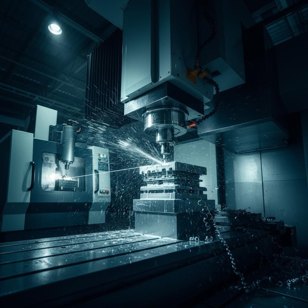
CNC Frezeleme ile EDM Teknolojileri Karşılaştırması
Kalıp bileşenlerinin işlenmesi söz konusu olduğunda CNC (Bilgisayar Sayısal Kontrolü) frezeleme, en yaygın kullanılan yöntemdir. Frezeler, tornalar ve taşlama merkezleri, iş parçasına karşı dönen kesici uçlarla mekanik kesme hareketiyle malzeme kaldırarak istenen geometrileri oluşturur. Erişilebilir özelliklere sahip basit kalıp bileşenleri için CNC frezeleme, üstün hız ve maliyet etkinliği sunar.
CNC frezeleme aşağıdaki durumlarda üstün performans gösterir:
- Özellikler, engel oluşturmadan çoklu açılardan erişilebilir.
- İç köşe yarıçapları, standart kesici uç çaplarını karşılayabilir.
- Malzemenin sertliği, ısıl işlem öncesi yaklaşık 45 HRC değerinin altında kalır.
- Üretim süreleri daha hızlı teslimat gerektirmektedir.
- Maliyet optimizasyonu birincil önceliktir.
Ancak parça geometrileri, kesme takımlarının ulaşamayacağı özellikler gerektirdiğinde ne olur? İşte burada Elektrik Deşarj ile İşleme (EDM) devreye girer. Sektörün imalat kaynaklarına göre EDM, geleneksel yöntemlerle ulaşılamayan karmaşık özellikleri hassas işleyerek oluşturmak için yüksek doğrulukta işleyebilme teknikleri kullanır.
Geleneksel EDM (Aynı zamanda batırma EDM veya ram EDM olarak da bilinir.) Şekillendirilmiş bir elektrot kullanır ve bu elektrot iş parçasına ‘batırılır’. Elektrot ile iş parçası arasındaki elektrik deşarjları, elektrotun aynası şeklindeki şekliyle malzemeyi aşındırır. Bu süreç, geleneksel yöntemlerle işlenmesi imkânsız olan karmaşık iç boşluklar —örneğin enjeksiyon kalıp çekirdekleri ya da düzensiz geometrilere sahip derin kalıp cepleri— oluşturur.
Geleneksel EDM'nin avantajları şunlardır:
- Sertleştirilmiş malzemelerde karmaşık üç boyutlu boşluk oluşturma
- İnce özelliklerin bozulmasına neden olabilecek mekanik kesme kuvvetleri yoktur
- Ön sertleştirilmiş takım çelikleriyle (60+ HRC) çalışabilme yeteneği
- İkincil işlemlere gerek kalmadan ince yüzey kalitesi elde edilebilir
Tel Erozyon farklı bir yaklaşım benimser. Şekillendirilmiş bir elektrot yerine, ince bir pirinç veya bakır tel (genellikle 0,004" ile 0,012" çapında), iş parçası içinden elektrik yüklü bir bant testeresi gibi geçer. Bu süreç, olağanüstü hassasiyetle karmaşık profilleri keser — ve işte bu, metal şekillendirme kalıpları için özellikle değerli kılan unsurdur.
Göre uzmanlaşmış işleme uzmanları , tel EDM, geleneksel CNC işleme yöntemlerine kıyasla birkaç belirgin avantaj sunar:
- Benzersiz şekiller: Aşırı ince tel, diğer yöntemlerin ulaşamadığı hassasiyetle karmaşık profilleri keser
- Malzeme sertliği bağışıklığı: Inconel, titanyum ve hatta karbür gibi sert malzemeler—CNC takımlarının kendisinin yapıldığı malzemeler—işlem, mekanik kuvvet yerine elektrikle çalıştığı için kolayca işlenebilir
- Sıkı toleranslar: ±0,0002" (±0,005 mm) hassasiyet, son derece sıkı spesifikasyonlar gerektiren parçalarda sağlanabilir
- Dik köşeler: 0,004" (0,10 mm) kadar ince tel çapları, freze uçlarının eşleşemeyeceği kadar dar köşe yarıçaplarını keser; bu, küçük boşlukların parça kalitesini etkilediği kalıp kalıpları için kritiktir
- Tutarlılık: Tel EDM, yüksek tekrarlanabilirlikle aynı anda birden fazla parçayı işleyebilir; hatta insan müdahalesi olmadan de çalışabilir
Ana uzlaşma noktası? Hız ve maliyet. Tel EDM, CNC tornalama/frezeleme işlemlerine kıyasla daha yavaş keser ve makine çalışma saat ücretleri genellikle daha yüksektir. Ancak sertleştirilmiş malzemelerde sıkı toleranslar gerektiren hassas kalıp takımları için bu teknoloji, yeniden işleme ihtiyacını ortadan kaldırarak ve ilk geçişte doğrudan doğru sonuç elde ederek genellikle toplamda daha ekonomik olur.
Kalıp Ömrü İçin Takım Çeliği Seçimi
İmalat yöntemi seçimi, malzeme seçimiyle el ele yürür. Kalıplarınız için belirtilen takım çeliği sınıfları, aşınmaya dayanıklılık, tokluk ve sonunda bakım gereksinimi duyulmadan önce üretebileceğiniz parça sayısını doğrudan etkiler.
Kalıp imalatı uzmanlarına göre, kalıplar için yaygın olarak kullanılan malzemeler arasında mükemmel sertlik ve aşınmaya dayanıklılık sağlayan takım çelikleri ile yüksek gerilimli uygulamalarda üstün dayanıklılık sağlayan karbür bulunmaktadır. İşte birincil seçeneklerin karşılaştırması:
D2 Kesici Çelik birçok sac kesme uygulaması için sektör standardını temsil eder. Bu yüksek karbonlu, yüksek kromlu çelik şu özellikleri sunar:
- Uzun üretim serileri için mükemmel aşınmaya dayanıklılık
- Isıl işlem sırasında iyi boyutsal stabilite
- 60–62 HRC’ye kadar sertlik kazanma özelliği
- Performans ve işlenebilirlik açısından maliyet etkin bir denge
D2, aşındırıcı aşınmanın ana endişe kaynağı olduğu kesme punch’ları, şekillendirme kalıpları ve genel amaçlı uygulamalar için iyi çalışır. Ancak tokluğu—darbe altında çatlamaya karşı direnci—bazı diğer alternatiflerin gerisinde kalır.
A2 Takım Çeliği bazı aşınma dirençlerini artırılmış tokluk için feda eder. Bu hava ile sertleşebilen çelik şu özellikleri sunar:
- Darbe etkisi altında çatlamaya ve kırılmaya karşı daha iyi direnç
- Isıl işlem öncesi iyi işlenebilirlik
- Yağla soğutulan kaliteye kıyasla sertleştirme sırasında daha düşük distorsiyon
- 57–62 HRC sertlik aralığına ulaşma kabiliyeti
Kalıplar şok yüklemesine maruz kaldığında veya kesme işlemi sırasında kalıba darbe kuvveti ileten daha kalın malzemeler işlendiğinde A2 tercih edilen seçenektir.
Karbür takımları en zorlu aşınma durumlarına çözüm sunar. Wolfram karbür, olağanüstü sertliğe sahiptir (herhangi bir takım çeliğinden önemli ölçüde daha serttir) ve aşırı aşınma koşullarında bile keskin kenarlarını korur. Kalıp üreticileri karbürü genellikle aşağıdaki amaçlarla kullanır:
- Milyonlarca çevrimi aşan yüksek hacimli üretimde kullanılan delme uçları
- Paslanmaz çelik gibi aşındırıcı malzemeleri kesen kalıp butonları
- Değişim sıklığının en aza indirilmesi gereken uygulamalar
Karbür ile ilgili uzlaşmazlık nedir? Kırılganlık. Karbür, aşınmaya mükemmel direnç gösterir ancak darbe yüklemesi altında çatlayabilir. Modern karbür kompozitleri bu özelliği geliştirmiştir; ancak uygulamalar yine de ilgili kuvvetlerin dikkatli bir şekilde değerlendirilmesini gerektirir.
Üretim Yöntemi Seçim Rehberi
Üretim yöntemleri arasında seçim yapmak, birden fazla faktörü dengelemeyi gerektirir. Bu karşılaştırma, kalıp bileşenlerinin üretimi için her yaklaşımın en mantıklı olduğu durumları özetlemektedir:
| Üretim yöntemi | En İyi Uygulamalar | Hassas Nivo | Maliyet Dikkate Alınması |
|---|---|---|---|
| CNC makineleme | Erişilebilir özellikler, 45 HRC’nin altında ön sertleştirilmiş malzemeler, kalıp tabanları, tutucular, genel bileşenler | tipik olarak ±0,001" ile ±0,0005" arası | Daha düşük saatlik ücretler, daha hızlı çevrim süreleri, standart geometriler için en ekonomik çözüm |
| Geleneksel EDM | Karmaşık 3B boşluklar, kapalı cepler, sertleştirilmiş kalıp iç parçaları, enjeksiyon kalıp özellikleri | ±0,0005" ile ±0,0002" arası hassasiyet elde edilebilir | Daha yüksek saatlik ücretler, elektrot maliyetleri ek gider oluşturur; karmaşık iç özellikler için haklıdır |
| Tel Erozyon | Yüksek hassasiyetli punch ve kalıp profilleri, dar toleranslı açıklıklar, sertleştirilmiş takım çelikleri ve karbür, karmaşık çevre kesimleri | ±0,0002" ulaşılabilir | Orta ila yüksek saatlik ücretler; hassas kalıp takımları için mükemmeldir ve birden fazla tezgâh ayarını ortadan kaldırır |
Çoğu metal şekillendirme kalıbı, bu yöntemlerin kombinasyonlarını kullanır. Kalıp tabanları (die shoes), önceden sertleştirilmiş plakadan CNC ile işlenebilir. Delici profilleri (punch profiles), hassasiyeti korumak amacıyla ısıl işlem sonrası tel eritme ile kesilebilir. Karmaşık şekillendirme boşlukları (forming cavities), iç yüzey özelliklerinin oluşturulması için geleneksel EDM yöntemini gerektirebilir; son yüzey parlaklığını sağlamak üzere ise taşlama işlemi gerekebilir.
Temel bilgi: Üretim yöntemi, parçanın özellik gereksinimlerine uygun olarak seçilmelidir. CNC ile mükemmel şekilde işlenebilecek özellikler için tel eritme (wire EDM) yöntemine gereğinden fazla yatırım yapmak bütçeyi israf eder. Bunun tersine, EDM hassasiyeti gerektiren geometriler için yalnızca CNC yöntemlerini zorla uygulamak, başlangıçtaki tasarrufun çok daha fazlasını maliyet olarak doğuracak kalite sorunlarına yol açar.
Malzeme ve imalat yöntemi kararları, kalıp performansı için temel oluşturur. Ancak mükemmel şekilde üretilmiş olsa bile kalıpların akıllıca uygulanması gerekir—üretim hacminize ve parça karmaşıklığınıza en uygun kalıp türünü bilmek, yatırımınızdan maksimum getiri elde edip edemeyeceğinizi belirler.
Uygulamanız için Doğru Kalıp Tipini Seçme
Kalıp türlerini, şekillendirme işlemlerini, malzemeleri ve imalat yöntemlerini anlıyorsunuz—ancak işte tüm bu bilgileri bir araya getiren soru şu: Belirli durumunuza gerçekten uygun olan hangi sac kesme kalıbıdır? Cevap sadece teknik yetenekle ilgili değildir. Ekonomik faktörler, zaman çizelgesi ve üretim ihtiyaçlarınızın zaman içinde nasıl gelişeceği de bu kararı etkiler.
Farklı şekillendirme kalıpları arasında seçim yapmak, başlangıç yatırımı ile uzun vadeli parça başına maliyet arasındaki dengeyi kurmayı, karmaşıklık ile kapasiteyi birbirine uyumlandırmayı ve ürünler olgunlaştıkça gereksinimlerin nasıl değişebileceğini öngörmeyi gerektirir. Şimdi, pratikte kullanabileceğiniz somut bir karar verme çerçevesi oluşturalım.
Hacime Dayalı Kalıp Seçim Kriterleri
Üretim hacmi, kalıp türü seçiminin temel belirleyicisidir—ve bu eşik değerler sizi şaşırtabilir. Yüksek üretim hacimlerinde önemli bir yatırım gerektiren özel metal presleme kalıpları tamamen mantıklıdır; ancak düşük üretim miktarları için ekonomik olarak gerekçelendirilemez.
İşte üretim hacminin genellikle kalıp seçimini nasıl etkilediği:
500 adetten az parça: Tek vuruşlu kalıplar veya hatta manuel şekillendirme işlemleri çoğunlukla en ekonomik çözümü sunar. Kalıp yatırımı minimum düzeyde tutulur ve tasarım yinelemeleri için yüksek esneklik sağlanır. Evet, parça başına işçilik maliyetleri daha yüksektir; ancak bu durum, başlangıçta çok düşük kalıp yatırım maliyetiyle telafi edilir.
500 ila 10.000 parça: Bu orta hacimli aralık ilginç bir noktadır. Bileşik kalıplar veya basit bileşik kalıp sistemleri ekonomik olarak anlamlı hale gelmeye başlar. Üretilen parça sayısı, sınırlı bir kalıp yatırımı ile işçilik maliyetlerinde azalma ve tutarlılıkta iyileşme sağlanmasını sağlayacak kadar fazladır—ancak karmaşık ilerleyici sistemlerin haklı çıkarılmasını sağlayacak kadar değildir.
10.000 ila 50.000 parça: Kombinasyon kalıpları ve daha basit ilerleyici kalıplar devreye girer. Şekillendirme üretim süreci daha otomatik hâle gelir, çevrim süreleri düşer ve parça başına maliyetiniz önemli ölçüde azalır. Kalıp yatırımı artar ancak geri ödeme süreleri oldukça kısalır.
50.000+ parça: Bu hacimde ilerleyici kalıplar, çoğu uygulama için açık ara lider konuma gelir. Sektör tecrübesine göre, ilerleyici kalıp ekonomisinin daha basit alternatifleri geçtiği kesişim noktası genellikle bu aralıkta yer alır; ancak kesin eşik değerleri parça karmaşıklığına ve malzeme maliyetlerine büyük ölçüde bağlıdır.
500.000+ parça: Bu hacimlerde çevrim süresindeki her saniyenin onda biri bile önem kazanır. Entegre sensörler, otomatik hurda kaldırma ve kalıp içi kalite izleme özelliklerine sahip yüksek verimlilikte optimize edilmiş ilerleyici kalıplar maksimum verimliliği sağlar. Önemli olan kalıp yatırımı, yeterince çok parçaya yayıldığından parça başına maliyet yalnızca malzeme maliyetine yaklaşır.
Parça Karmaşıklığı Dikkate Alınacak Hususlar
Hacim yalnızca yarım hikâyeyi anlatır. Parça geometrisi ve tolerans gereksinimleri, üretim miktarından bağımsız olarak hangi şekillendirme yöntemlerinin uygulanabilir olduğunu önemli ölçüde etkiler.
Bu karmaşıklık faktörlerini göz önünde bulundurun:
- Özellik sayısı: Birden fazla delik açma, bükme ve şekillendirme işlemi gerektiren parçalar, işlemlerini sıralı olarak tamamlayan ilerlemeli veya taşımalı kalıpları tercih eder.
- Boyutsal ilişkiler: Özellikler arasındaki sıkı toleranslar en çok önem kazandığında, aynı anda işlemleri gerçekleştiren bileşik kalıplar genellikle üstün doğruluk sağlar.
- Üç boyutlu derinlik: Derin çekmeli veya yoğun şekillendirme gerektiren parçalar, iş parçalarının istasyonlar arasında bağımsız olarak taşındığı taşımalı kalıplar gerektirebilir.
- Parça boyutu: İlerlemeli işlemler sırasında şerit bağlantısını koruyamayan büyük bileşenler, taşımalı veya tek istasyonlu yaklaşımlar gerektirir.
- Malzeme akışı gereksinimleri: Kontrollü metal akışıyla gerçekleştirilen karmaşık çekme işlemleri, daha basit kalıpların karşılayamayacağı sac tutucu sistemleri gerektirir.
Görünüşte üç kıvrıma ve iki deliğe sahip basit bir bağlantı parçası, beş istasyonlu ilerlemeli kalıp üzerinde verimli çalışabilir. Ancak kabartmalı özelliklere ve kıvrımlı kenarlara sahip derin çekme yöntemiyle üretilen bir kupa, benzer hacimlerde bile bir taşıma sistemi gerektirebilir—geometri bunu zorunlu kılar.
Prototipten Yüksek Hacimli Üretim Aşamasına
Birçok mühendisin gözden kaçırdığı şey şudur: Ürünler kavram aşamasından üretim olgunluğuna geçtikçe kalıp gereksinimleri de değişir. Geliştirme sırasında mantıklı görünen kalıp, tam üretim kapasitesinde ihtiyaç duyulan kalıpla genellikle aynı değildir.
Akıllı bir yaklaşım şu yolu izler:
- Kavram doğrulaması (1–50 parça): Hızlı prototipleme yöntemleriyle başlayın—lazer kesim, pres bükme veya yumuşak kalıplama. Amacınız, tasarımın işe yaradığını kanıtlamak; üretim verimliliğini optimize etmek değil. Tasarım sabit hâle gelene kadar yatırımınızı en aza indirin.
- Tasarım iyileştirmesi (50–500 parça): Basit sert kalıpçılığa geçiş—tek vuruşlu kalıplar veya temel bileşik kalıplar. Bu, parça üretiminin (dövme ile şekillendirilmesinin) mümkün olduğunu doğrular ve aynı zamanda tasarım ayarlamaları için esneklik sağlar. Bu aşamada özel metal dövme kalıpları, yetenek ile revizyon riski arasında bir denge kurar.
- Ön üretim (500–5.000 parça): Üretim temsili kalıpçılığa yatırım yapın. Bu, basitleştirilmiş ilerleyici bir kalıp ya da iyi tasarlanmış kombinasyon kalıpları anlamına gelebilir. Bu aşamadan çıkan parçalar, nihai testleri, uygunluk değerlendirmelerini ve ilk müşteri sevkıyatlarını destekler.
- Üretim artırımı (5.000–50.000 parça): Ön üretim sırasında edinilen tecrübeler doğrultusunda kalıpçılığı optimize edin. Ön üretim sürecinde gözlenen aşınma desenlerini giderin, gerçek malzeme davranışına göre boşlukları iyileştirin ve operatör müdahalesini azaltan otomasyon özelliklerini ekleyin.
- Olgun üretim (50.000+ parça): Tamamen optimize edilmiş üretim kalıplarını devreye alın. En yüksek istasyon verimliliğine sahip ilerleyici kalıplar, entegre kalite izleme ve dayanıklı bakım imkânları sunarak büyük ölçekli üretimde toplam sahiplik maliyetini en aza indirir.
Bu aşama yaklaşımı, riski akıllıca yönetir. Tasarımlar hâlâ esnek iken karmaşık ilerlemeli kalıpçılığa yatırım yapmazsınız; ancak üretim hacimleri, gelişmiş şekillendirme üretim çözümlerini haklı çıkardığında üretim verimliliğinizi de kısıtlamazsınız.
Uygulamalı Karar Çerçevesi
Kalıp türü seçeneklerini değerlendirirken bu sistematik süreci uygulayın:
- Üretim hacmi tahmininizi belirleyin: Sadece mevcut ihtiyaçları değil, aynı zamanda 12-24 ay için gerçekçi tahminleri de göz önünde bulundurun. Ürün olgunlaştıkça üretim hacimleri artacak mı, sabit kalacak mı yoksa azalacak mı?
- Parça karmaşıklığını haritalayın: Delme, kesme, şekillendirme, çekme gibi gerekli tüm operasyonları listeleyin. Kritik toleransları ve yüzey kalitesi gereksinimlerini belirleyin.
- Tasarım kararlılığını değerlendirin: Mevcut tasarımın nihai olduğuna ne kadar eminsiniz? Bekleyen revizyonlar, daha basit ve daha esnek kalıpçılığı gerektirir.
- Kesişim maliyetlerini hesaplayın: Hacminizi karşılayan birden fazla kalıp türü için teklif alın. Daha basit ve daha karmaşık kalıplar arasında parça başına maliyet kesişimi nerede gerçekleşir?
- Bakım ve takım değişimi faktörlerini dikkate alın: Daha karmaşık kalıplar, daha ileri düzey bakım gerektirir. Atölyeniz ilerlemeli kalıplama konusunda deneyime sahip değilse, öğrenme sürecini de dikkate alın.
- Teslim süresi gereksinimlerini göz önünde bulundurun: İlerlemeli kalıpların tasarımı ve imalatı daha uzun sürer. Piyasaya çıkış hızı önemliyse, daha basit kalıplarla üretimi daha erken başlatabilirsiniz.
- Gelecek için planlayın: Bu ürün ailesi genişleyecek mi? Gelecekteki varyantları da destekleyebilecek kalıplar, başlangıçta daha yüksek yatırım yapmayı haklı çıkarabilir.
Tek bir kalıp türü her durumda üstün değildir. Doğru seçim, bu kriterlere göre kendi özel durumunuzu dürüstçe değerlendirerek — anlık ihtiyaçlarla uzun vadeli verimlilik arasındaki dengeyi sağlayarak — ortaya çıkar.
Akıllı kalıp seçimi, başarılı üretim için sahneyi hazırlar. Ancak mükemmel şekilde seçilmiş kalıplar bile performanslarını korumak için sürekli dikkat gerektirir. Yaygın aşınma desenlerini, arıza modellerini ve bakım uygulamalarını anlayarak yatırımınızın hizmet ömrü boyunca kaliteli parçalar üretmesini sağlarsınız.
Kalıp Bakımı ve Sorun Gidermenin Temelleri
Kaliteye odaklı kalıplara yatırım yaptınız, doğru kalıp türünü seçtiniz ve şekillendirme sürecinizi optimize ettiniz—ancak birçok üreticiyi şaşırtan bir gerçek şudur: En iyi çelik kalıplar bile zamanla bozulur. Her pres vuruşu performansı biraz daha azaltır ve uygun bakım yapılmadığı takdirde hassas kalıplarınız, kalite güvencesi yerine kalite sorunlarının kaynağı haline gelir.
Kalıp bakımını, önleyici sağlık hizmetleri gibi düşünün. Sorunları erken tespit etmek, acil tamiratlardan çok daha düşük maliyetlidir ve üretim hattınızı sorunsuz bir şekilde çalışır durumda tutar. Buna göre the Phoenix Group şirketinin sektör uzmanlarına göre kötü kalıp bakımı, üretim sırasında kalite kusurlarına neden olur; bu da sınıflandırma maliyetlerini artırır, kusurlu parçaların sevkiyatının yapılma olasılığını yükseltir ve pahalı zorunlu içerme işlemlerine yol açma riskini doğurur.
Yaygın Kalıp Aşınma Desenlerini Tanımak
Sorunları çözebilmek için önce onları okumanız gerekir. Kalıptan çıkan parçalardaki her çizik, kenar dikişi (burr) ya da boyutsal sapma, kalıbınızın içinde ne olduğunu anlatan bir hikâye anlatır. Bu sinyalleri yorumlayabilmeyi öğrenmek, tepkisel acil müdahaleyi proaktif yönetimden ayırır.
Oturmalı aşınma kalıp yüzeylerinden yavaş yavaş malzeme kaybı şeklinde ortaya çıkar; bu, parlak alanlar, yüzeysel oluklar ya da kalıp açıklıklarında boyutsal büyüme olarak gözlemlenebilir. Bu aşınma deseni, sert parçacıkların (pas tabakası, kir, işlenecek malzemenin işlenmeden sonra sertleşmiş parçacıkları) kalıp yüzeyleri üzerinde kayması sonucu gelişir. Malzeme ile temasın en yoğun olduğu yerlerde, yani kalıp plakası kenarlarında ve punch yüzeylerinde bu aşınmayı ilk olarak fark edersiniz.
Yapışkan Aşınma (Galling) tamamen farklı görünür. Pürüzsüz aşınma yerine, iş parçası malzemesinin kalıp yüzeyine kaynaklandığı ve ardından koparıldığı yırtık, pürüzlü yüzeyler görürsünüz. Tıkanma bir kez başladığında hızla ilerler—her ardışık çevrim daha fazla malzeme kopararak yüzey hasarını giderek daha şiddetli hâle getirir. Paslanmaz çelik ve alüminyum bu arıza türüne özellikle yatkındır.
Yorulma aşınması ince yüzey çatlakları şeklinde ortaya çıkar; bu çatlaklar zamanla birleşerek malzemenin pul pul dökülmesine veya soyulmasına neden olur. Bu desen genellikle tekrarlayan yükleme çevrimlerine maruz kalan yüksek gerilim bölgelerinde görülür. Kalıp plakası yüzeyi başlangıçta sorunsuz görünse de mikroskopik inceleme, yayılmaya hazır stres çatlağı ağları gösterir.
Darbe hasarı kırılma, çatlama veya lokal deformasyon şeklinde görülür—genellikle presin içindeki yanlış besleme, çift vuruş veya yabancı madde gibi belirli olaylara dayandırılabilir. Kademeli aşınma desenlerinin aksine, darbe hasarı aniden ortaya çıkar ve çoğunlukla acil müdahale gerektirir.
Göre Jeelix'in teknik kaynakları bu aşınma türlerini doğru bir şekilde ayırt etmek, doğru tedavi yöntemini belirlemenin ilk adımıdır. Aşındırıcı aşınmayı yağlama değişiklikleriyle tedavi etmek işe yaramaz—daha sert takım malzemelerine veya kaplamalara ihtiyacınız vardır. Buna karşılık, yapraklanmayı (galling) kalıp sertliğini artırarak gidermeye çalışmak, sorunun temel nedenini tamamen göz ardı eder.
Dikkat Gerektiren Uyarı İşaretleri
Felaket niteliğinde bir arıza beklemeyin. Bu belirtiler, makinenizin kalıplarının incelenmesi veya bakım gerektirdiğini gösterir:
- Kenar kıvrım yüksekliğinde artış: Kabartılar (burrs) kabul edilebilir sınırları aştıkça, punch ile kalıp arasındaki açıklığın aşınma sonucu arttığını gösterir.
- Boyutsal Sürüklenme: Parçaların tolerans sınırlarının yavaş yavaş dışına çıkması, kalıp yüzeylerinin aşındığını veya bileşenlerin yer değiştirdiğini gösterir.
- Parçalardaki yüzey çizikleri: Şekillendirilmiş yüzeylerdeki doğrusal izler, kalıp yüzeylerinde hasar oluştuğunu veya artık birikimi olduğunu gösterir.
- Şekillendirme derinliğinde tutarsızlık: Değişken çekme derinlikleri veya bükme açıları, aşınmış baskı pedleri veya tutarsız kalıp pres hizalamasını işaret eder.
- Artan şekillendirme kuvveti: Tonaj gereksinimlerindeki artış, genellikle yağlamanın bozulduğunu veya yüzey koşullarının kötüleştiğini gösterir.
- Anormal ses veya titreşim: Presin sesinde veya hissindaki değişiklikler, çoğu zaman görünür sorunlardan önce ortaya çıkar.
- Soyulmuş veya sıkışmış parçalar: Şekillendirilmiş parçaların çıkarılmasındaki zorluk, yüzeyde yapışma (galling) veya soyucu fonksiyonun yetersiz olduğunu gösterir
Önleyici Bakım En İyi Uygulamalar
Reaktif bakım—kusurlara neden olan sorunlar ortaya çıktıktan sonra onarımla ilgilenmek—önleyici bakıma kıyasla önemli ölçüde daha fazla maliyet gerektirir. Sistematik bir yaklaşım, dövme kalıplarınızın ve şekillendirme takımlarınızın en yüksek verimle çalışmasını sağlarken kullanım ömrünü de uzatır.
Önerilen bakım aralıkları:
- Her vardiyada: Görünür hasarlar için görsel kontrol, yağlama doğrulaması, kalıp yüzeylerinden hurda ve artıkların temizlenmesi
- Her 10.000–25.000 vuruda: Kesme kenarları, şekillendirilmiş yüzeyler ve kılavuz bileşenlerinin ayrıntılı kontrolü; kritik boşlukların ölçümü
- Her 50.000–100.000 vuruda: Kalıbın tamamen sökülmesi, kapsamlı temizliği, tüm aşınma yüzeylerinin boyutsal doğrulaması ve yayların değiştirilmesi gerekliliğinin değerlendirilmesi
- Her 250.000–500.000 vuruşta: Kapsamlı yeniden inşa değerlendirmesi, yüzey yenileme işlemi veya kaplama yenilenmesi, kılavuz bileşenlerinin değiştirilmesi
Bu aralıklar, malzeme sertliği, yağlama etkinliği ve parça karmaşıklığına göre değişir. Yüksek mukavemetli çelik uygulamalarında bu aralıkların yarısında muayene yapılması gerekebilirken, yumuşak alüminyum şekillendirme işlemlerinde bu aralıklar uzatılabilir.
Belgeleme son derece önemlidir. The Phoenix Group’un kalıp bakım kılavuzlarına göre, iş emri sistemi, bir kuruluşun tüm kalıp tamir veya bakım faaliyetlerini belgelemesine, takip etmesine, önceliklendirmesine ve zamanlamasına olanak tanır. Tamamlanan iş emirleri, gerçekleştirilen işlemleri ayrıntılı şekilde açıklamalı ve sorunların tekrarlanma durumunu izlemek için gerekli imkânları sağlamalıdır.
Yeniden taşlama ile Yenileme Kararları
Aşınma kabul edilebilir sınırları aştığında, mevcut kalıbı onarmak mı yoksa yeni bileşenlere yatırım yapmak mı gerektiği konusunda kritik bir karar vermeniz gerekir. Bu karar, birkaç faktöre bağlıdır.
Yeniden taşlama aşağıdaki durumlarda mantıklıdır:
- Aşınma düzgün dağılmıştır ve malzemenin yeniden taşlanma payı içinde kalır (genellikle toplamda 0,5–2 mm)
- Çatlak, kırık veya yapısal hasar yoktur
- Kalıp geometrisi, işlevi bozmadan malzeme kaldırılmasına izin verir
- Yeniden taşlama maliyeti, yedek bileşen maliyetinden önemli ölçüde düşüktür
- Yedek bileşenin teslim süresi üretim programı toleransını aşıyor
Yerine koyma şu durumlarda gerekli hale gelir:
- Aşınma, kalıp tasarımı sırasında belirlenen maksimum yeniden taşlama sınırlarını aşıyor
- Yorulma çatlakları yüzeyel hasarı aşarak ilerlemiştir
- Boyutsal doğruluk yalnızca taşlama işlemiyle sağlanamaz
- Bileşen birden fazla kez yeniden taşlanmıştır ve malzeme tükenmiştir
- Isı hasarı, takım çeliğinin sertliğini veya mikroyapısını değiştirmiştir
Akıllı kalıp tasarımı, yüksek aşınma bölgelerinde değiştirilebilir takımların kullanılmasını öngörerek bu kararı önceden planlar. Tüm kalıp plakalarını yeniden taşlamak veya değiştirmek yerine, maliyetin ve durma süresinin yalnızca bir kesirini oluşturarak takımları değiştirirsiniz.
Hedef, bakımı ortadan kaldırmak değil—ki bu imkânsızdır. Hedef, bakımı öngörülemeyen bir krizden, üretim kesintilerini en aza indirirken kalıp değerini maksimize eden yönetilen bir süreç haline dönüştürmektir. Uygun dikkat gösterildiğinde, kaliteli çelik kalıplar, önemli müdahale gerektirmeden yıllarca güvenilir hizmet vererek milyonlarca hassas parça üretir.
Otomotiv Endüstrisi Uygulamaları ve Kalite Standartları
Kalıp seçimi, bakımı ve arıza giderme konularında uzmanlaşmış bulunuyorsunuz—ancak burada şimdiye kadar tartıştığımız her şey, otomotiv üretiminde en yüksek seviyede sınanacaktır. Bu sektör, sac metal kalıplarını yalnızca kullanmakla kalmaz; onlardan mükemmellik ister. Tek bir kusurlu pres parçası, milyonlarca dolarlık ürün geri çağırmasına neden olabildiğinde, risk daha fazla olamaz.
Otomotiv sektörü, metal pres kalıbı teknolojisi için nihai test ortamını oluşturur. Sektörün kalite uzmanlarına göre, iyi yapılmış bir kalıp ve kesme takımı, başarılı presleme operasyonlarının temelidir; doğru şekilde üretilmiş bir kalıp, sıkı kalite standartlarını karşılamak için gerekli olan tutarlı ve tekrarlanabilir parçalar üretir.
OEM Kalite Standartlarını Karşılamak
Neden otomotiv pres kalıpları, diğer sektörler için üretilen takımlara kıyasla daha fazla maliyet gerektirir ve geliştirilmesi daha uzun sürer? Bunun cevabı, hiçbir hata payı bırakmayan sertifikasyon gereksinimlerinde yatmaktadır.
IATF 16949 sertifikasyonu, otomotiv tedarik zincirleri için küresel kalite yönetim standardı haline gelmiştir. Uluslararası Otomotiv Görev Gücü tarafından oluşturulan bu sertifikasyon, tedarikçilerin her seviyesinde tutarlı kalitenin sağlanmasını garanti eder. Pres kalıbı üreticileri için IATF standartlarını karşılamak şunları ifade eder:
- Kalıp tasarımının ve imalatının her yönü için belgelenmiş süreçler
- Üretim süreci boyunca istatistiksel süreç kontrolü
- Ham maddeden bitmiş takım ürünne kadar tam izlenebilirlik
- Kusurları tanımlayan ve ortadan kaldıran sürekli iyileştirme sistemleri
- Müşteriye özel gereksinimlerin kalite sistemlerine entegrasyonu
Bunun pratikte ne anlama geldiğini merak ediyor musunuz? Şekillendirme kalıbı tedarikçiniz, yalnızca yetkinliği değil, aynı zamanda sistematik mükemmelliği de kanıtlamalıdır. Shaoyi bu yaklaşımı aşağıdakiyle örneklemektedir: IATF 16949 sertifikalı operasyonları , en talepkar OEM spesifikasyonlarını karşılayacak şekilde katı kalite yönetimi ile ileri düzey mühendislik yeteneklerini bir araya getirir.
İlk geçiş onay oranları, yeterli kalıp tedarikçilerini olağanüstü olanlardan ayıran kritik ölçüttür. Yeni bir sac metal kalıbı üretim sürecine girdiğinde, ilk parçaların yeniden işlenmeye veya ayarlama gerektirmeden teknik özelliklere uygun çıkması ne sıklıkla gerçekleşir? Sektörün liderleri %90’ı aşan oranlar elde eder—Shaoyi ise %93'lük bir ilk geçiş onay oranı bildirmektedir; bu oran, kaliteli kalıp geliştirme için bir referans değerdir.
Neden bu kadar büyük bir öneme sahiptir? Alternatif senaryoyu düşünün. Her başarısız deneme turu şu anlamına gelir:
- Sorunların teşhis edilmesi için ek mühendislik saatleri
- Reddedilen deneme parçalarından kaynaklanan malzeme atığı
- Üretim dışı faaliyetler tarafından tüketilen pres süresi
- Araç piyasaya sürme takvimlerine yayılan proje gecikmeleri
- Kalıp sınırlamalarına uyum sağlamak amacıyla potansiyel tasarım uzlaşmaları
İlk geçiş başarısı oranında %70 ile %93 arasındaki fark, doğrudan geliştirme zaman çizelgesi ve bütçeye yansır—genellikle haftalarca süren bir zaman çizelgesi sıkıştırılması ve önemli miktarda maliyet tasarrufu anlamına gelir.
CAE Simülasyonun Hata İçermeyen Sonuçlara Nasıl Yönlendirdiği
Bu etkileyici ilk geçiş oranlarına ulaşmak tesadüfen gerçekleşmez. Modern otomotiv kalıp geliştirme süreci, herhangi bir çelik kesilmeden önce metal kalıp tasarımlarını doğrulamak için Bilgisayar Destekli Mühendislik (CAE) simülasyonuna büyük ölçüde dayanır.
Otomotiv prototipleme uzmanlarına göre, CAD modelleri modern geliştirme sürecinin başlangıç noktasını oluşturur—bu dijital projeler üretim süreçlerini yönlendirir, hassasiyet ve doğruluğu sağlarken fiziksel kalıba geçmeden önce değişiklik yapılmasını da mümkün kılar.
Gelişmiş CAE simülasyon yetenekleri, mühendislerin şu işlemleri yapmasını sağlar:
- Malzeme akışını, incelme oranını ve potansiyel arıza noktalarını sanal ortamda öngörün
- Deneme aşamasından önce sac tutucu basınçlarını ve çekme çubuğu konfigürasyonlarını optimize edin
- Dijital yinelemeler aracılığıyla geri yayılma telafi stratejilerini doğrulamak
- Pahalı fiziksel prototipleme gerektirecek biçimlendirme sorunlarını belirleyin
- Geliştirme döngülerini aylardan haftalara indirin
Bu simülasyon odaklı yaklaşım, sac metal kalıp geliştirme maliyetlerini temelden değiştirir. Daha önce çok sayıda fiziksel deneme iterasyonu gerektiren —her biri pres zamanı, malzeme ve mühendislik kaynakları tüketen— sorunlar, artık yalnızca hesaplama süresi gerektiren sanal ortamlarda çözülebilmektedir.
Hızlı Prototipleme ile Geliştirme Sürecinin Hızlandırılması
Otomotiv geliştirmede hız önemlidir. Araç programları agresif zaman çizelgeleriyle yürütülür ve kalıp geliştirmedeki gecikmeler, üreticilerin gelirinde milyonlarca dolarlık kayba neden olabilecek lansman takvimine yansıyan sorunlara yol açar.
Hızlı prototipleme teknolojileri, otomotiv bileşenlerinin kavramdan üretime geçiş sürecini kökten değiştirmiştir. Hidaka USA'nın otomotiv araştırmasına göre, hızlı prototipleme, 3D yazdırma ve CNC frezeleme gibi teknolojileri kullanarak prototipleri haftalar yerine günler içinde üretmeyi sağlayarak, erken geliştirme aşamalarında pahalı kalıpçılık ihtiyacını ortadan kaldırır.
Faydalar yalnızca basit hızdan ibaret değildir:
- Tasarım doğrulaması: Fiziksel modeller, üretim için kalıpçılığa geçilmeden önce şekil, uyum ve işlev açısından test edilebilir
- Maliyet etkinlik: Erken aşama prototipleri, henüz değişebilecek tasarımlar için sert kalıpçılığın maliyetini önler
- Paralel geliştirme: Birden fazla tasarım varyantı aynı anda prototiplenebilir; bu da karar verme sürecini hızlandırır
- Müşteri onayı: Fiziksel numuneler, müşteri incelemesini ve geri bildirim entegrasyonunu daha erken dönemlerde mümkün kılar
Prototip üretim sürelerini haftalardan sadece 5 güne düşürmeyi hayal edin. Tam da bu, Shaoyi gibi öncü tedarikçilerin entegre hızlı prototipleme ve üretim kalıpçılığı yetenekleriyle sunduğu çözümdür. Bu kısaltılmış zaman çizelgesi, mühendislik ekiplerinin tasarım yinelemelerini daha hızlı gerçekleştirmesine, kavramları daha erken doğrulamasına ve üretim kalıplarına daha büyük güvenle geçmesine olanak tanır.
Prototipten Yüksek Hacimli Üretim Aşamasına
Prototip parçalardan üretim için hazır sac metal pres kalıplarına geçiş, dikkatli bir planlama gerektirir. Otomotiv bileşenleri, prototip doğrulama aşamasında mı yoksa yüksek hacimli üretimde mi üretiliyor olursa olsun, aynı teknik özelliklere uygun olmak zorundadır — ve kalıplar, bu tutarlılığı milyonlarca çevrim boyunca sağlamalıdır.
Hızlı kalıpçılık geliştirilmesini sağlayan temel teknolojiler şunlardır:
- 3D baskı karmaşık prototip geometrileri ve sabitleme aparatlarının geliştirilmesi için
- CNC makineleme dar toleranslar gerektiren hassas bileşenler için
- Tel Erozyon karmaşık profillere sahip sertleştirilmiş kalıp bileşenleri için
- Hızlı Aletleme prototipleme ile seri üretimi birbirine bağlayan çözüm
Sektör kaynaklarına göre, hızlı kalıpçılık, nihai ürüne mümkün olduğunca yakın prototipler oluşturmak için hayati öneme sahiptir—böylece seri üretim başlamadan önce hızlı yinelemeler ve ayarlamalar yapılabilir.
Otomotiv sektörünün yüksek talepleri, sac metal şekillendirme kalıpları teknolojisini en yüksek düzeyde hassasiyet, güvenilirlik ve verimlilik seviyesine taşımıştır. Burada edinilen dersler—titiz kalite sistemleri, simülasyonla doğrulanmış tasarımlar ve hızlı geliştirme yetenekleri—basılmış bileşenlerin önemli olduğu her sektörde geçerlidir.
Yeni bir araç platformu başlatıyor olmanız ya da mevcut sac işleme operasyonlarınızı yalnızca iyileştirmeyi hedefliyor olmanız fark etmez; temel ilkeler aynıdır: kaliteli kalıplamaya yatırım yapın, çelik kesiminden önce tasarımları titizlikle doğrulayın ve kalite beklentilerinize uygun yeteneklere sahip tedarikçilerle ortaklık kurun. Böylece tasarım kusurları kusursuz parçalara dönüşür.
Sac Metal Şekillendirme Kalıpları Hakkında Sıkça Sorulan Sorular
1. Sac metal şekillendirme işlemlerinde kullanılan farklı kalıp türleri nelerdir?
Beş temel kalıp türü şunlardır: yüksek hacimli sürekli işlemler için kullanılan ilerleyici kalıplar; aynı anda kesme ve delme işlemlerini gerçekleştiren bileşik kalıplar; kesme ve şekillendirme işlemlerini tek bir vuruşta birleştiren kombinasyon kalıpları; büyük parçalarda karmaşık çok istasyonlu işlemler için kullanılan taşıma kalıpları; daha basit, düşük hacimli uygulamalar için kullanılan tek-vuruşlu kalıplar. İlerleyici kalıplar, 100.000+ parça üretiminde üstün performans gösterirken, bileşik kalıplar, özellikler arası sıkı doğruluk gerektiren orta hacimli üretimler için uygundur. Taşıma kalıpları, ilerleyici şerit beslemesi için çok büyük olan parçaları işleyebilir ve tek-vuruşlu kalıplar, prototipleme ve sık tasarım değişiklikleri için esneklik sağlar.
2. Eğme, çekme ve kabartma gibi şekillendirme işlemlerinin birbirleriyle farkı nedir?
Bükme, hava bükme, oturtma veya para basma yöntemleriyle açısal özellikler oluşturur—her biri farklı düzeylerde geri yaylanma kontrolü sağlar. Derin çekme, sac parçaları üzerinde boşluk tutucular kullanarak metal akışını kalıp boşluklarına yönlendirerek düz sac plakaları kavanoz şeklinde veya üç boyutlu parçalara dönüştürür. Kabartma işlemi, malzemenin delinmesine neden olmadan yüzeyde kabartılı veya çukur şekiller oluşturur; genellikle logolar veya takviye kaburgaları için kullanılır. Her işlem farklı mekanik ilkelerden yararlanır: bükme, belirli büküm çizgilerinde kontrollü plastik deformasyona dayanır; derin çekme, buruşma veya yırtılma oluşumunu önlemek için dengeli malzeme akışını gerektirir; kabartma ise yerel, yüzeysel bir deformasyon oluşturur.
3. Farklı malzemeler için uygun punch ve kalıp aralığı nasıl hesaplanır?
Kalıp boşluğu, malzemenin kalınlığı ile o özel metal için önerilen boşluk yüzdesi çarpılarak hesaplanır. Alüminyum için her bir tarafta %12–16, yumuşak çelik için %16–20, paslanmaz çelik için %18–24 ve bakır için en dar aralık olan %10–14 boşluk gerekir. Örneğin, 2,0 mm kalınlığında yumuşak çelik için toplam boşluk 0,34–0,40 mm olmalıdır. Doğru boşluk, tane sınırları kırılma düzlemlerini hizalayarak temiz kesim sağlar; boşluğun çok dar olması kesici takımın aşınmasını hızlandırır ve fazla ısı oluştururken, çok geniş olması kenar bölgelerinde kenar döküntüsüne (bur) neden olur ve ikincil bitirme işlemlerini gerektirir.
4. Dayanıklı saclı parçalar şekillendirme kalıplarının üretimi için en uygun takımlı çelikler hangileridir?
D2 takım çeliği, endüstride standart olarak kabul edilir ve maksimum 62 HRC sertlik değerine sahip mükemmel aşınma direnci sunar; bu nedenle kesme punch’ları ve genel şekillendirme uygulamaları için idealdir. A2 takım çeliği, bir miktar aşınma direncini artırılmış toklukla değiştirir; bu da kalıpların darbeli yükleme altında çalıştığı veya daha kalın malzemeler kesildiği durumlarda tercih edilmesini sağlar. Karbür uçlar, en zorlu aşınma koşullarına karşı çözüm sunar ve milyonlarca çevrim sonrasında bile keskin kenarlarını korur. Seçim, belirli uygulama kuvvetleriniz ve üretim hacmi gereksinimlerinize göre aşınma direnci ile darbe tokluğunu dengelemeye dayanır.
5. Otomotiv üreticileri, ilk geçişte onay alınarak yüksek kaliteli sac metal parçaları nasıl üretebilir?
Yüksek ilk geçiş onay oranlarına ulaşmak, IATF 16949 sertifikalı kalite sistemleri, sanal kalıp doğrulaması için gelişmiş CAE benzetimi ve hızlı prototipleme kapasitesi gerektirir. Shaoyi gibi öncü tedarikçiler, malzeme akışını, incelmesini ve geri yaylanmayı çelik kesilmeden önce tahmin eden, simülasyon odaklı tasarımı sıkı kalite yönetimiyle birleştirerek %93'lük ilk geçiş onay oranı elde eder. Şirketin en az 5 gün içinde gerçekleştirdiği hızlı prototipleme, geliştirme sürecinin erken aşamalarında tasarım doğrulamasına olanak tanır; kapsamlı kalıp tasarımı yetenekleri ise üretim kalıplarının başlangıçtan itibaren talepkâr OEM spesifikasyonlarını karşılamasını sağlar.