 Küçük partiler, yüksek standartlar. Hızlı prototip hizmetimiz doğrulamayı daha hızlı ve kolay hale getirir —

Metal İşleme Parçalarının Sırları: Malzeme Seçiminden Nihai Muayeneye Kadar
Bir Metal İşleme Parçasını Tanımlayan Nedir
Bir hassas bileşeni elinizde tuttuğunuzda — belki bir vana gövdesi, bir dişli mili ya da bir hidrolik bağlantı parçası — bu kadar kesin boyutlara nasıl ulaştığını hiç merak ettiniz mi? Cevap genellikle metal işlemede gizlidir; bu üretim yaklaşımı, modern sanayiyi bir asırdan fazla süredir şekillendirmektedir. Bir metal makineler parçası işleme parçası, istenen geometrinin ortaya çıkması için katı bir iş parçasından sistematik olarak malzeme kaldırılarak oluşturulan herhangi bir bileşendir. Malzeme ekleme veya yeniden şekillendirme işlemi yapan süreçlerden farklı olarak, işleme ham malzemeden hassasiyeti kazandırır.
Metal işleme, kesici takımların katı bir metal iş parçasından malzeme kaldırarak kesin nihai boyutları, toleransları ve yüzey kalitesini elde ettiği, diğer üretim yöntemlerinin ulaşamadığı düzeyde hassasiyete sahip bir çıkarımlı üretim sürecidir.
İşlenmiş parçaların neyin onları benzersiz kıldığını anlamak, daha akıllı tedarik kararları vermenize yardımcı olur. Bileşenleri belirten bir mühendis ya da tedarikçileri değerlendiren bir satın alma profesyoneli olmanız fark etmez; burada ele alınan temel bilgiler, ilerleyen bölümlerde malzemeler, süreçler ve uygulamalar konusunda yolunuzu gösterecektir.
Çıkartmalı İmalat İlkesi
Katı bir alüminyum bloğundan başlayıp ait olmayan her şeyi yavaşça keserek çıkarmayı hayal edin. Bu, çıkarımsal üretim yönteminin en basit hâlidir. Metal işlemenin kendisi, son parça kalana kadar talaş ve kırpıntılar kaldırmak amacıyla dönen kesme takımları, torna tezgâhları veya taşlama diskleri kullanmayı içerir. Bu prensip, malzemenin katman katman birikerek oluşturulduğu 3B yazdırma gibi eklemeli yöntemlerle doğrudan zıtlaşır.
Bu yaklaşımın güzelliği nedir? Zaten bilinen, tutarlı mekanik özelliklere sahip bir malzemeyle başlarsınız. Çubuk malzeme ve gövde parçaları, torna atölyesine ulaşmadan önce kalite kontrolünden geçirilir. Kesme işlemi başladığında, öngörülebilir malzeme davranışlarıyla çalışırsınız — diğer yöntemleri sıkıntıya sokabilen katman yapışması veya gözeneklilik konusunda endişe duymazsınız.
İşlenen Parçaların Diğer Metal Bileşenlerden Farkı
Tüm metal parçalar eşit değildir. Bu farklılıkları anlamak, uygulamanız için doğru imalat yöntemini belirtmenize yardımcı olur:
- Döküm Parçalar ergimiş metalin kalıba dökülüp katılaşmasıyla oluşur. Karmaşık geometrilerde üstün performans gösterirler; ancak iç gözenekliliğe sahip olabilirler ve dayanımı azaltan rastgele tane yapılarına sahiptirler.
- Dövülmüş Parçalar metalin tane yapısını hizalayan sıkıştırma kuvvetleriyle şekillenirler ve olağanüstü dayanım sağlarlar. Ancak dövme işlemi pahalı kalıplar gerektirir ve tasarım özgürlüğünü sınırlar.
- Sac Parçalar saç metalinden delinir veya şekillendirilir; yüksek hacimli düz veya hafif çıkıntılı bileşenler için idealdir ancak üç boyutlu hassas özellikler için uygun değildir.
- Metal işlenmiş parçalar en yüksek boyutsal doğruluğu sunar — genellikle ±0,05 mm veya daha sıkı toleranslar sağlar — üstün yüzey kalitesine sahiptir ve düşük üretim hacimleri için herhangi bir kalıp yatırımı gerektirmez.
PrimeFabWorks’ta üretim uzmanlarına göre, tornalama işlemi çubuk malzemenin orijinal mukavemetini korurken, döküm ve dövme işlemlerinin ikincil işlemler olmadan ulaşamadığı bir hassasiyet düzeyi sunar. Bunun karşılığı nedir? Katı malzemeden üretilen parçaların tornalanması malzeme atığına neden olur ve yakın-net-şekil (near-net-shape) süreçlere kıyasla çok yüksek üretim hacimlerinde maliyet açısından daha az verimli hale gelir.
Bu temel anlayış, takip eden her şeye zemin hazırlar. Bir sonraki bölümlerde, malzeme seçiminin işlenebilirlik üzerindeki etkisini, farklı geometriler için hangi CNC süreçlerinin uygun olduğunu ve toleranslar ile yüzey pürüzlülüğünün hem fonksiyonu hem de maliyeti nasıl etkilediğini öğreneceksiniz. Amacımız basittir: Sizleri, işlenmiş metal parçaları güvenle ve verimli bir şekilde tedarik edebilmeniz için gerekli bilgilerle donatmak.
İşlenen Parçalar İçin Malzeme Seçimi Kılavuzu
Doğru metali seçmek, sadece işi yapacak kadar dayanıklı bir şey seçmekten ibaret değildir. İşlenebilirlik, performans ve maliyetin tümünün projenizin gereksinimleriyle uyumlu olduğu 'tatlı noktayı' bulmak anlamına gelir. Bu kararı yanlış verirseniz, daha uzun çevrim süreleriyle, aşırı kesici takım aşınmasıyla veya hizmet sırasında başarısız olan parçalarla karşılaşabilirsiniz. Doğru kararı verirseniz ise verimli üretimden ve tam olarak tasarlandığı gibi çalışan bileşenlerden yararlanırsınız.
Aşağıdaki kılavuz, alüminyum işlemenin, paslanmaz çelik uygulamalarının ve özel malzeme çalışmalarının en yaygın olarak kullanılan metallerini açıklar. Gerçek dünya gereksinimlerine malzeme özelliklerini nasıl uyumlandıracağınızla ilgili pratik içgörüler bulacaksınız — bunlar; havacılık bağlantı parçaları üretiyorsanız , tıbbi cihazlar veya endüstriyel bağlantı elemanları üretiliyor olsa da.
| Malzeme | İşlenebilirlik Derecesi | Çekim gücü (Mpa) | Korozyon Direnci | Maliyet Faktörü | Tipik Uygulamalar |
|---|---|---|---|---|---|
| Alüminyum 6061 | Mükemmel | 310 | İyi | Bu | Havacılık bağlantı parçaları, otomotiv muhafazaları, tüketici elektroniği |
| Malzeme 303 Paslanmaz Çelik | İyi | 620 | Orta derecede | Orta | Bağlantı elemanları, sabitleme elemanları, valf bileşenleri |
| ST Çelik 316L | Orta derecede | 485 | Mükemmel | Orta-Yüksek | Tıbbi cihazlar, denizcilik donanımı, gıda işleme |
| 1.4301 (304 Paslanmaz Çelik) | Orta derecede | 515 | Çok iyi. | Orta | Mutfak ekipmanları, mimari aksesuarlar, tanklar |
| 360 Pirinç | Mükemmel | 385 | İyi | Orta | Dekoratif donanım, tesisat armatürleri, elektrik bağlantı elemanları |
| C110 bakır | İyi | 220 | Orta derecede | Orta-Yüksek | Elektrik bara baraları, ısı emicileri, topraklama bileşenleri |
| Titanyum Sınıf 5 | Fakirler | 950 | Mükemmel | Yüksek | Havacılık yapısal parçaları, tıbbi implantlar, yarış parçaları |
Hafif Ağırlıklı Hassas İşleme İçin Alüminyum Alaşımları
Hız ve maliyet verimliliği en çok önemli olduğunda alüminyum işlemenin mükemmel sonuçlar verdiği bilinir. Alüminyum 6061, işlemenin dünyasında gerçek bir iş atıdır — ve bunun iyi bir nedeni vardır. Yüksek termal iletkenliği sayesinde aşırı ısınmadan daha hızlı kesme hızlarına imkân tanır; bu da daha kısa çevrim sürelerine ve azaltılmış takım aşınmasına yol açar. Ethereal Machines’ın işlemen uzmanlarına göre, alüminyum 6061, daha sert metallerle karşılaştırıldığında işlenme süresini %20’ye kadar kısaltabilir; bu nedenle yüksek hacimli üretim süreçleri için idealdir.
Alüminyum, işlenmiş parçalar için neden bu kadar çekici bir malzemedir?
- Mükemmel İşlenebilirlik - Talaşlar kolayca temizlenir ve yüzey kalitesi, minimum çaba ile pürüzsüz çıkar
- Hafif ağırlıkla güçlü yapısı - Çelikten yaklaşık üçte bir ağırdır ancak kabul edilebilir çekme mukavemet özelliklerini korur
- Doğal korozyon direnci - Çevresel bozulmaya karşı dirençli koruyucu bir oksit tabakası oluşturur
- Anodize Uyumluluğu - Dayanıklılığı ve estetiği artırmak için yüzey işlemlerini son derece iyi kabul eder
Daha yüksek mukavemet gerektiren uygulamalar için, alüminyum 7075, bazı çeliklere yaklaşan çekme özelliklerine sahiptir; ancak bu, biraz daha düşük işlenebilirlik ve daha yüksek malzeme maliyeti anlamına gelir.
Paslanmaz Çelik Sınıfları ve Aralarındaki Üstünlükler-Düşüklükler
Paslanmaz çelik, her mühendisin anlaması gereken ilgi çekici bir üstünlük-düşüklük dengesi sunar. Harika korozyon direnci sağlayan aynı krom içeriği, kesme sırasında malzemenin işlenebilirliğini zorlaştıran ve kesici takım aşınmasını artıran bir iş sertleşmesine neden olur.
303 paslanmaz çelik bu sorunu zarif bir şekilde çözer. Kükürt ilavesi, talaş kırıcı olarak çalışan küçük inklüzyonlar oluşturur ve bu da paslanmaz çeliğin beklenen korozyon direncinin büyük bölümünü korurken işlenebilirliği önemli ölçüde artırır. Daha zor işlenebilir sınıfların getirdiği zorluklar olmadan paslanmaz çelik özelliklerine ihtiyaç duyduğunuzda tercih etmeniz gereken malzemedir.
ST çelik 316L, korozyon direncini her şeyin üzerinde önceliklendiren farklı bir yaklaşım benimser. Bu "L" işareti, düşük karbon içeriğini ifade eder; bu da kaynak işlemi sırasında karbür birikimini önler ve ısı etkilenmiş bölgede korozyon direncini korur. Tıbbi cihaz üreticileri, 316L'yi tekrarlayan sterilizasyon döngülerine bozulmadan dayanabilmesi nedeniyle tercih eder. Deniz uygulamaları ise deniz suyu maruziyeti için bu malzemeyi gerektirir. Pazarlık noktası nedir? 303'e kıyasla %30-40 daha uzun talaş kaldırma süreleri bekleyin.
Avrupa numaralandırması 1.4301, dünya genelinde en yaygın olarak kullanılan paslanmaz çelik sınıfı olan 304 paslanmaz çeliği anlamına gelir. Bu çelik, işlenebilirlik ile korozyon performansı arasında orta bir konumdadır ve böylece gıda işleme ekipmanlarından mimari bileşenlere kadar genel amaçlı uygulamalar için uygundur.
Talep Yüksek Uygulamalar İçin Özel Metaller
Bazen standart malzemeler yeterli olmaz. Uygulamanızın olağanüstü elektriksel iletkenlik, termal performans veya aşırı dayanıklılık gerektirdiği durumlarda, özel metaller gerekli hâle gelir — maliyetlerinin yüksek olması ve işlenmesindeki zorluklar göz ardı edilse bile.
Brass 360 (serbest işlenebilir pirinç olarak da bilinir), işlenmesi en kolay metallerden biridir. İşlenebilirlik indeksi genellikle serbest işlenebilir çelik referans değerini aşar ve minimum takım aşınmasıyla mükemmel yüzey kalitesi sağlar. Görünüşü ve iletkenliği aynı derecede önemli olduğu hassas bağlantı parçalarında, dekoratif donanımlarda ve elektrik bağlantı elemanlarında bu malzemeyle karşılaşacaksınız. Orta düzeyde mukavemeti, üstün işlenebilirliği ve çekici altın rengi kombinasyonu, Brass 360’ı hem fonksiyonel hem de estetik bileşenler için tercih edilen bir malzeme haline getirir.
Bakır 110, %99,9 saflıkta en saf ticari bakır sınıfıdır ve elektriksel veya termal iletkenliğin ödün verilemeyeceği uygulamalarda kullanılır. Isı emiciler, baralar ve topraklama bileşenleri genellikle C110 bakırını belirtir çünkü diğer yaygın metallerin hiçbiri iletkenliğiyle kıyaslanamaz. Bakırın işlenmesi, talaş kontrolüne dikkat gerektirir — bu malzeme, ilerleme ve devir sayıları optimize edilmediğinde kesici takımlara dolanabilen uzun, ipimsi talaşlar üretme eğilimindedir.
Titanyum, spektrumun uç noktasını oluşturur. Dayanım/ağırlık oranı neredeyse tüm diğer metallere göre daha yüksektir ve korozyon direnci değerli metallere eşdeğerdir. Ancak titanyumun düşük termal iletkenliği, ısıyı talaş aracılığıyla dağıtmak yerine kesme kenarında yoğunlaşmasına neden olur. Bu durum, daha düşük devir sayıları, sert montajlar ve özel kesici takımlar gerektirir. Ayrıca JLCCNC not ediyor titan, yalnızca performans gereksinimlerinin tüm diğer unsurları bastığı sektörlerde mali olarak avantajlıdır — havacılık, tıbbi implantlar ve yüksek performanslı yarışlar akla gelen örneklerdir.
Bu malzeme özelliklerini anlamak, bir sonraki kritik kararınız olan: seçtiğiniz malzemeyi nihai bir bileşene dönüştürecek işlevsel işlem yöntemi hangisi olmalıdır? Parçanızın geometrisi ile malzeme seçiminizin birleşimi, frezeleme, tornalama ya da çok eksenli işleme yöntemlerinden hangisinin en uygun çözüm olduğunu belirler.
CNC Machining Süreçleri Açıklanmıştır
Malzemenizi seçtiniz — şimdi ne yapacaksınız? Parçanızın geometrisi, onu en verimli şekilde üretmek için hangi imalat işleminin kullanılacağını belirler. Eğimli yüzeylere ve iç boşluklara sahip karmaşık bir muhafaza ile silindirik bir mil tamamen farklı üretim yaklaşımları gerektirir. Bu farkları anlamak, tedarikçilerinizle etkili iletişim kurmanıza ve hem maliyetleri hem de teslim sürelerini önceden tahmin etmenize yardımcı olur.
Metal ile çalışıyorsanız, metal için CNC makinesi basit prizmatik parçalarla çalışan ya da havacılık bileşenleri için gelişmiş çok eksenli yeteneklere ihtiyaç duyan sistemlerde doğru süreç seçimi, verimli üretim ile maliyetli tezgâh ayarları arasındaki farkı yaratır. Şimdi temel CNC metal işleme operasyonlarını ve her birinin ne zaman en iyi performans gösterdiğini inceleyelim.
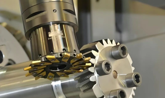
CNC Frezeleme Operasyonları ve Yetenekleri
Frezeleme, iş parçasına yukarıdan veya yandan temas eden dönen çok uçlu kesici takımlar kullanarak malzeme kaldırma işlemidir. Dönen bir uç freze takımı, katı bir bloğa kanallar, cepeler ve kontürler açarken hayal edin — işte bu, frezelemenin çalışır hâlidir. Bu çok yönlü işlem, basit düz yüzeylerden karmaşık 3B profillere kadar her şeyi işleyebilir.
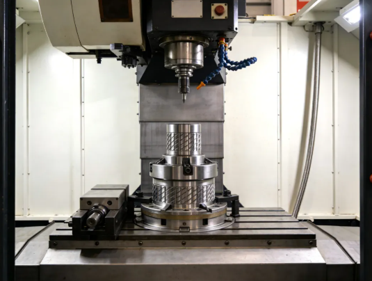
CNC metal kesme makinenizin ekseni sayısı, mümkün olacak geometrileri belirler:
- 3-Eksen Frezeleme - Spindel, X, Y ve Z yönlerinde hareket eder. Düzlemsel freze profilleri, delikler ve tek bir yönelime göre hizalanmış özellikler için en uygundur. Daha basit parçalar için maliyet açısından avantajlıdır; ancak farklı yüzlerdeki özellikler için birden fazla tezgâh ayarı gerektirir.
- 4-Eksen Frezeleme - İş parçasını X ekseni etrafında döndüren döner A ekseni ekler. İş parçasının yeniden konumlandırılması gerekmeden yaylar, helisler ve açılı özellikler boyunca sürekli kesim yapılmasını sağlar. Buna göre CNC El Kitabı , bu yapılandırma, birden fazla yüzeyinde özelliklere sahip parçalar için kurulum süresini önemli ölçüde azaltır.
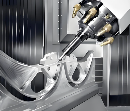
- 5 Eksenli Frezeleme - Kesme takımının iş parçasına neredeyse her açıdan yaklaşmasına izin veren iki döner eksen içerir. Bu, karmaşık havacılık bileşenleri, türbin kanatları ve şekillendirilmiş yüzeylere sahip tıbbi implantlar için hayati öneme sahiptir.
Çok eksenli frezeleme ne zaman belirtilmelidir? Parçanızda silindirik yüzeylerde delikler veya özellikler, açılı kesimler veya sürekli helisel profiller gerekiyorsa 4 eksenli frezeleme düşünülmelidir. Bileşik eğrileri, değişken açılarda takım erişimi gerektiren derin boşlukları olan parçalar veya birden fazla kurulumu ortadan kaldırmak makine ücretindeki artışın haklı çıkarılmasını sağlıyorsa 5 eksenli frezeleme tercih edilmelidir.
Pratik bir ipucu: Parçanızı 3 eksenli bir makinede bir veya iki kurulumda tamamlayabiliyorsanız, maliyet tasarrufu genellikle daha fazla eksene sahip olmanın kolaylığını aşıyor. Kararınız, kurulum süresi ve işlemler arasındaki tolerans birikimi sınırlayıcı faktörler haline geldiğinde değişir.
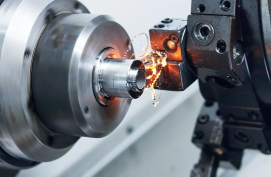
Silindirik Parçalar İçin Torna İşleme ve Torna Çalışmaları
Frezeleme prizmatik şekillerde üstün performans gösterirken, torna işleme yuvarlak parçalar dünyasına hükmeder. Bu süreçte iş parçası dönerken tek noktalı kesici bir takım malzeme kaldırır — bu, frezelemede dönen takım yaklaşımının tam tersidir. Miller, pimler, burçlar ve dönme simetrisine sahip herhangi bir bileşen genellikle bir tornada işlenmeye başlar.
CNC tornalama yetenekleri şunları içerir:
- Dış tornalama - Dış çapları, konikleri, olukları ve dişleri oluşturur
- İç delik genişletme (boring) - Delikleri, hassas çap kontrolüyle genişletir ve işler
- Karşılaştıkça - Dönme ekseniyle dik düz yüzeyler üretir
- Iş parçacığı - Standart veya özel özelliklere göre iç veya dış dişleri işler
Modern CNC tornaları genellikle hareketli takımlı işlevi – parçanın bağlanmış durumda kalırken düz yüzeyler, delikler ve kanallar işleyebilen motorlu freze mili – içerir. Bu freze-torna yeteneği, aksi takdirde farklı makineler arasında aktarım gerektirecek tamamlanmış parçaları tek bir montajda üretir. Teklifte "tornalanmış özelliklere sahip CNC freze parçaları" ifadesini gördüğünüzde, muhtemelen freze-torna işlemiyle üretilen parçalardan bahsedilmektedir.
Tornalanmış ayaklar veya kabartmalar içeren sac metal bağlantı parçalarının işlenmesi için bazı atölyeler lazer kesimi ile ikincil tornalama işlemlerini birleştirir. Ancak çoğu sac metal işi geleneksel tornalama işlemlerinin dışındadır ve bunun yerine şekillendirme, delme veya lazer işlemleri kullanılır.
Parçayı Tamamlayan İkincil İşlemler
Birincil işlemenin genellikle tüm hikâyeyi anlatmadığı bilinir. Çoğu CNC freze parçası ve tornalanmış bileşen, tam olarak bitirilmeden önce ikincil işlemler gerektirir.
Taşlama, kesme takımlarının elde edemeyeceği yüzey kaliteleri ve toleransları sağlar. Yatakların mil yuvalarının mikron düzeyinde yuvarlaklıkla tutulmasını veya sızdırmazlık yüzeylerinin ayna gibi pürüzsüzlüğe kavuşmasını gerektirdiğinde taşlama işlemi zorunlu hâle gelir. Silindirik taşlama, dairesel parçaları işlerken yüzey taşlaması düz özelliklere uygulanır. Xometry'nin belirttiği üzere taşlama, son parlatma işlemlerinden önce yüzeyleri kabul edilebilir seviyeye getiren bir bitirme işlemidir.
Karşılaşabileceğiniz diğer ikincil işlemler şunlardır:
- Delik Açma ve Taraklama - Birincil tornalama sırasında pratik olmayan vida delikleri eklemek
- Broaching - Dişli bir takım kullanarak anahtar kanalları, dişli profilleri ve iç profilleri kesmek
- Honing - Hidrolik silindirler ve benzeri uygulamalar için delik yüzey kalitesini ve geometrisini iyileştirmek
- Çöpe çekme - İşlem güvenliği ve fonksiyonellik açısından kesme işlemlerinden sonra oluşan keskin kenarları kaldırmak
Prototip muhafazalar için alüminyum işlerken CNC tezgâhında zaman kazanmak amacıyla bazı ikincil işlemlerden geçebilirsiniz. Ancak seri üretim parçaları genellikle tüm teknik şartnamelerin karşılandığından emin olmak için tam bir işlem sırasından geçer.
Parçanızın hangi işlemlere ihtiyaç duyduğunu bilmek, teklifleri akıllıca değerlendirmenizi sağlar. Rakiplerine kıyasla önemli ölçüde daha düşük bir teklif veren bir tedarikçi, diğerleri tarafından dahil edilen işlemleri dışlamış olabilir — ya da belirli geometriniz için daha verimli ekipmanlara sahip olabilir. Her iki durumda da işlem zincirini bilmek, bilgilendirilmiş kalmanızı sağlar.
İşlemler seçildikten ve anlaşıldıktan sonra bir sonraki kritik soru ortaya çıkar: Bu işlemler boyutları ne kadar hassas tutabilir ve aslında hangi toleransları belirtmelisiniz? Cevap, parça geometrisinden malzeme davranışına kadar değişen faktörlere bağlıdır — bu konuları bir sonraki bölümde ayrıntılı olarak inceleyeceğiz.
Metal İşlemede Toleranslar ve Hassasiyet
İşte makine atölyelerinde günlük olarak gerçekleşen bir senaryo: Bir mühendis, daha sıkı toleransların her zaman daha iyi olduğunu düşünerek tüm çizim boyunca ±0,001" toleransları belirtir. Sonuç? Teklifler beklenenin üç katı kadar yüksek gelir ve teslim süreleri günlerden haftalara uzar. Gerçek şu ki, hassas işlenmiş metal parçalar her zaman aşırı toleranslara ihtiyaç duymaz; bunlara ihtiyacın olan şey, - Evet. toleransların uygulandığı - Evet. özellikler.
Tolerans belirtimi konusunda bilinçli alıcılar ile fazla ödeme yapan ya da yetersiz spesifikasyon yapanlar arasındaki ayrımı oluşturur. İşlenmiş alüminyum bağlantı parçaları mı kullanıyorsunuz yoksa sertleştirilmiş çelikten karmaşık işlenmiş parçalar mı? İlkeler aynıdır: Neye ihtiyacınız varsa, nerede ihtiyacınız varsa ve bundan fazlasını değil, tam olarak onu belirtin.
| Tolerans Sınıfı | Tipik Aralık | İşleme Yöntemi | Uygulamalar | Maliyet Etkisi |
|---|---|---|---|---|
| Genel İşleme | ±0,25 mm (±0,010") | Standart CNC frezeleme/ tornalama | Kritik olmayan ölçüler, geçiş delikleri, genel muhafazalar | Başlangıç |
| Hassas işleme | ±0,05 mm (±0,002") | Sıcaklık kontrollü CNC, hassas sabitleme aparatları | Rulman geçmeleri, birleşen yüzeyler, hizalama özellikleri | %50-%100 artış |
| Yüksek Hassasiyet | ±0,0125 mm (±0,0005") | Hassas miller, çevre kontrol sistemleri | Optik bileşenler, tıbbi cihazlar, havacılık arayüzleri | %100-200 artış |
| Ultra Hassas | ±0,0025 mm (±0,0001") | Taşlama, honlama, özel donanım | Kalibre blokları, metroloji standartları, yarı iletken üretim ekipmanları | %300+ artış |
Standart Tolerans Sınıfları ve Her Birinin Uygulandığı Durumlar
Uluslararası standartlar, tolerans belirtimi için ortak bir dil sağlar. ISO 2768 standardı, genel toleransları f (ince), m (orta), c (kaba) ve v (çok kaba) olmak üzere dört hassasiyet sınıfı aracılığıyla tanımlar. Bu sınıflar, her özellik için ayrı ayrı belirtilmeye gerek kalmadan doğrusal boyutları, açısal boyutları ve geometrik karakteristikleri kapsar.
Bunun pratikte anlamı nedir? Çiziminizde ISO 2768-m belirttiğinizde, makine atölyesine listelenmemiş boyutların orta tolerans kurallarına tabi olacağını bildirmiş olursunuz. Örneğin, 50 mm’lik bir boyut için yaklaşık ±0,3 mm’lik bir varyasyona izin verilirken, 10 mm’lik bir özellik için yaklaşık ±0,1 mm’lik bir tolerans geçerlidir. Bu yaklaşım, çizimleri büyük ölçüde basitleştirirken aynı zamanda tutarlı kalite beklentilerini de garanti eder.
Standart CNC işlemenin — tipik atölye ortamlarında gerçekleştirilen türünün — güvenilir şekilde ±0,25 mm (±0,010") tolerans değerlerine ulaşması, temel kapasitesi olarak kabul edilir. Hassas imalat uzmanlarına göre, bu tolerans seviyesi, makine tezgâhı doğruluğundaki normal değişimleri, termal etkileri, kesici takım aşınmasını ve montaj tekrarlanabilirliğini ekonomik üretim oranlarını korurken karşılar.
Daha dar tolerans belirtmeniz ne zaman gerekir? Aşağıdaki yönergeleri göz önünde bulundurun:
- Birbirine temas eden yüzeyler - Parçaların kontrollü boşluk veya geçme ile bir araya gelmesi gereken yerlerde
- Rulman yuvaları ve miller - Dönüş doğruluğu ve kullanım ömrünü etkileyen hassas geçmeler
- Sızdırmazlık yüzeyleri - Yüzey geometrisi doğrudan sızdırmazlığı etkilediği yerlerde
- Hizalama Özellikleri - Bileşenleri konumlandıran yerleştirme pimleri, konumlandırma delikleri ve referans yüzeyler
Sadece yapısal amaçlarla kullanılan freze işlenmiş parçalar için — montaj braketleri, kapaklar, kritik olmayan muhafazalar — genel toleranslar genellikle yeterlidir. Bu özelliklere hassas tolerans spesifikasyonları uygulamak, işlevsel bir fayda sağlamadan maliyeti artırır.
Ulaşılabilecek Hassasiyeti Etkileyen Faktörler
Karmaşık mı görünüyor? Böyle olmak zorunda değil. Ulaşılabilecek toleranslar, öngörülebilir ve birbiriyle etkileşim halinde olan bir faktör kümesine bağlıdır. Bu ilişkileri anlamak, gerçekçi gereksinimler belirlemenize ve tedarikçi yeteneklerini değerlendirmenize yardımcı olur.
Malzemenin davranışı son derece önemlidir. Alüminyumun yaklaşık 23 × 10⁻⁶ /°C’lik termal genleşme katsayısı, 100 mm’lik bir alüminyum parçanın her 10°C sıcaklık artışında yaklaşık 0,023 mm uzamasına neden olur. Freze işlenmiş çelik bileşenler ise bu oranın yaklaşık yarısı kadar genleşir; bu da onları değişken ortamlarda daha boyutsal olarak kararlı hale getirir. Uygulamanız sıcaklık dalgalanmaları içeriyorsa, malzeme seçimi doğrudan ulaşılabilecek hassasiyeti etkiler.
Çelik işlenmesi kendi özel hususlarını beraberinde getirir. Bazı çelik türlerinde meydana gelen işlenebilirlik sertleşmesi, iç gerilmelerin yeniden dağılımı nedeniyle işlemenin ardından boyutsal değişimlere yol açabilir. Nihai işlemenin öncesinde doğru ısıl işlem uygulanması, boyutların sabitlenmesini sağlar ve karmaşık işlenmiş parçalarda daha dar toleransların sağlanmasını mümkün kılar.
Parça geometrisi pratik sınırlar oluşturur. İnce cidarlar kesme kuvvetleri altında sapar. Uzun ve ince özellikler bükülür. Derin cepeler takım rijitliğini sınırlandırır. Bu geometrik gerçeklerin her biri, özel bağlama elemanları veya çevrim süresini uzatan azaltılmış kesme parametreleri kullanılmadan elde edilebilecek tolerans seviyelerini etkiler.
Pratik bir örnek düşünelim: katı ve kompakt bir özellik üzerinde ±0,05 mm tolerans sağlamak doğrudan ve kolaydır. Aynı toleransın, 200 mm uzunluğunda ve 3 mm kalınlığında bir cidar üzerinde sağlanması ise dikkatli bağlama, hafif kesmeler ve kaba işleme ile bitirme işlemi arasında gerilim giderme işlemleri gerektirebilir. Bu durumun maliyet farkı önemli ölçüde olabilir.
Çevresel kontroller, hassasiyet seviyelerini birbirinden ayırır. Göre Modus Advanced sıcaklık değişimleri, CNC işlemenin toleranslarını etkileyen en önemli faktörlerden biridir. Standart atölye sıcaklık değişimleri ±3°C değerinde olabilir ve bu durum, sıkı tolerans aralıklarını aşacak kadar boyut kaymalarına neden olabilir. Yüksek hassasiyetli işler genellikle ±0,5°C kararlılığı sağlayan iklim kontrollü alanlar gerektirir.
Çizimlerde toleranslar nasıl belirtilmelidir? Aşağıdaki kanıtlanmış uygulamalara uygun hareket edin:
- Sadece gerçekten ihtiyaç duyulan işlevsel özelliklere sıkı toleranslar uygulayın
- Kritik olmayan boyutlar için genel tolerans blokları kullanın (ISO 2768 veya eşdeğeri)
- Gerekli olduğunda, kritik özellikler üzerinde doğru GD&T sembolleriyle özel toleransları doğrudan belirtin
- Yüksek hassasiyet gerekiyorsa malzeme durumu ve muayene sıcaklığı not edilmelidir
- Hangi özelliklerin en çok önem taşıdığını iş ortağınızla paylaşın
Tolerans spesifikasyonu ile maliyet arasındaki ilişki yaklaşık olarak üstel bir eğri izler. Ek bir ondalık basamaklık hassasiyet, üretim karmaşıklığını iki katına çıkarabilir. Tüm boyutları ±0,25 mm toleransla üretilen bir parça 50 $'a mal olabilirken, aynı parçanın tüm boyutları ±0,025 mm toleransla üretilmesi durumunda maliyeti işlevsel bir iyileşme sağlanmadıkça (yani bu sıkı toleranslar aslında gerekli değilse) 200 $'a yaklaşabilir.
Boyutsal hassasiyet anlaşıldıktan sonra dikkat edilmesi gereken başka bir spesifikasyon daha vardır: yüzey pürüzlülüğü. İşlenmiş yüzeylerde kalan dokunun, sızdırmazlık performansından yorulma ömrüne kadar her şeyi etkiler — bu konular, yüzey pürüzlülüğü seçeneklerini ve bunların işlevsel sonuçlarını incelediğimizde kritik hâle gelir.
Yüzey Pürüzlülüğü Seçenekleri ve İşlevsel Sonuçları
Toleransları tam olarak sağlamışsınız — ancak işlenen yüzeylerinizde geride kalan dokuya ne dersiniz? Yüzey pürüzlülüğü, görünüşte sadece estetik bir detay gibi görünebilir; ancak metal işlenmiş parçanızın kullanım sırasında gösterdiği performansı derinden etkiler. Aşırı pürüzlü bir conta yüzeyi sızdıracaktır. Aşırı pürüzsüz bir yatak yuvası yağlayıcıyı tutamayacaktır. Yüzey pürüzlülüğünü doğru belirlemek, mikroskopik dokuyu parçanızın işlevsel gereksinimlerine uygun hâle getirmeyi gerektirir.
Tüketicinin elektronik cihazları için alüminyum muhafazalar mı işliyorsunuz yoksa elektrikli montajlar için bakır kontaklar mı işliyorsunuz, yüzey pürüzlülüğü spesifikasyonlarını anlamanız, gereksinimleri açıkça iletmene ve tedarikçilerinizle maliyetli yanlış anlaşılmaları önlemene yardımcı olur.
Yüzey Pürüzlülüğü Ölçümleri ve Standartları
Yüzey pürüzlülüğü, işlenmiş bir yüzeyde kalan mikroskopik tepeleri ve çukurları nicelendirir. En yaygın metrik olan Ra (Ortalama Pürüzlülük), bir örnek uzunluğu boyunca merkez çizgisinden bu sapmaların aritmetik ortalamasını ölçer. Daha düşük Ra değerleri daha pürüzsüz yüzeyleri; daha yüksek değerler ise daha fazla dokuya işaret eder.
Göre Geomiq yüzey pürüzlülüğü rehberi , Üretim süreçlerinde elde edilen parçalar için Ra değerleri genellikle 0,1 µm (ayna parlaklığında pürüzsüz) ile 6,3 µm (belirgin şekilde pürüzlü) aralığında değişir. ISO 21920-2:2021 standardı, daha ayrıntılı yüzey karakterizasyonu gerektiren uygulamalar için Rz (ortalama maksimum yükseklik) ve Rt (toplam pürüzlülük yüksekliği) gibi ek metrikleri tanımlar.
İşte çoğu CNC torna ve freze tedarikçisinin sunduğu standart yüzey pürüzlülüğü seviyeleri:
- 3,2 µm Ra (İşleme sonrası standart) - Görünür takım izleri mevcuttur. Yüzey dokusu kritik olmayan genel amaçlı bileşenler, bağlantı parçaları ve muhafazalar için uygundur. Bu, ek maliyet olmadan uygulanan varsayılan yüzey işlemidir.
- 1,6 µm Ra (İnce işlenmiş) - Hafif kesim izleri neredeyse görünmez. Hafif yükler altında çalışan parçalar, yavaş hareket eden yüzeyler ve orta düzey sızdırmazlık gerektiren uygulamalar için önerilir. İmalat maliyetine yaklaşık %2,5 eklenmesine neden olur.
- 0,8 µm Ra (Yüksek kaliteli yüzey işlenmesi) - Elde edilmesi için bitirme geçişleri gerektirir. Gerilime duyarlı parçalar, titreşen bileşenler ve hareketli montajlar için idealdir. Üretim maliyetini yaklaşık %5 artırır.
- 0,4 µm Ra (Çok yüksek kaliteli/parlatılmış) - Gözle görülebilir kesim izi yoktur. Dikkatli makine işlemenin ardından parlatma işlemiyle elde edilir. Hızlı hareket eden eşleşen parçalar ve yüksek gerilim uygulamaları için en uygundur. Üretim maliyetine en fazla %15 ekleyebilir.
Estetik amaçlarla alüminyum bileşenler işlediğinizde, müşterilerin beklediği pürüzsüz ve profesyonel görünümü elde etmek için genellikle 0,8 µm Ra veya daha ince bir yüzey pürüzlülüğü belirtirsiniz. Bakır süs eşyalarının işlenmesinde de malzemenin doğal parlaklığını vurgulamak amacıyla benzer yüzey kalitesi hedeflenir.
Yüzey İşleme Gereksinimlerini Parça Fonksiyonuna Uydurma
Bir montajın içinde gizlenecek bir yüzeyde ayna parlaklığını belirtmeyi hayal edin — bu, fayda sağlamadan maliyet eklemek demektir. Buna karşılık, bir conta yüzeyinde standart pürüzlülüğü kabul etmek sızıntıları ve garanti taleplerini garantilemek demektir. Anahtar, yüzey işleme kalitesini işlevine uygun hâle getirmektir.
Yüzey pürüzlülüğü farklı uygulamaları nasıl etkiler?
- Sızdırmazlık yüzeyleri - Daha pürüzlü dokular, birbirine oturan yüzeyler arasında sızıntı yolları oluşturur. O-ring kanalları ve conta yüzeyleri genellikle sıvı kaçaklarını önlemek için 1,6 µm Ra veya daha ince bir yüzey pürüzlülüğüne ihtiyaç duyar.
- Aşınma Direnci - Şaşırtıcı bir şekilde, aşırı düz yüzeyler, yağlayıcıyı tutan mikro cepleri ortadan kaldırarak aşınmayı artırabilir. Kayma yüzeyleri genellikle 0,8–1,6 µm Ra aralığında en iyi performansı gösterir.
- Yorgunluk Yaşı - Yüzey düzensizlikleri, çatlakların başladığı gerilme yoğunlaşım noktaları olarak işlev görür. Dönüşlü yük altındaki parçalar, daha düzgün yüzeylerden — 0,8 µm Ra veya daha iyisinden — yararlanır.
- Estetik - Tüketiciye yönelik ürünler, görsel olarak çekici yüzey işlemlerini gerektirir. Dekoratif parçalar genellikle yansıtıcı ve premium görünüm elde etmek için 0,8 µm Ra’ya kadar işlenir veya cilalanır.
- Kaplamanın yapışması - Contur kaplama ihtiyaçlarına aykırı olarak, kaplamalar genellikle mekanik kilitleme sağlayacak şekilde hafifçe pürüzlü yüzeylere daha iyi yapışır. Kaplama öncesi ortamla kumlama işlemi yaygın bir uygulamadır.
CNC alüminyum kesim işlemleri, alüminyumun mükemmel işlenebilirliği sayesinde doğal olarak iyi yüzey kaliteleri üretir. Alüminyumda 1,6 µm Ra yüzey pürüzlülüğü elde etmek genellikle çok az ek çaba gerektirir; bu nedenle görünüm önemliyse temel seviyenin biraz üzerinde bir yüzey kalitesi belirtmek maliyet açısından verimlidir.
İşlenmeden sonra elde edilen yüzeylerin ötesinde, ikincil yüzey işleme işlemlerinin amacı, performansı veya görünümü artırmak için yüzey özelliklerini dönüştürmektir. Fictiv’in yüzey işleme kılavuzuna göre bu işlemler dönüştürme kaplamaları, kaplama ve mekanik işlemler olmak üzere üç gruba ayrılabilir:
- Anodizasyon (Tip II/III) - Alüminyum üzerine dayanıklı bir oksit tabakası oluşturur; bu tabaka korozyon direncini artırır ve boyanabilme imkânı sunar. Tip II işlemde boyutlara 0,02–0,05 mm, Tip III (sert kaplama) işlemde ise en fazla 0,1 mm eklenir.
- Elektroksız nikel kaplama - Çelik, paslanmaz çelik veya alüminyum üzerine homojen nikel-fosfor kaplaması uygular. Karmaşık geometrilerde mükemmel korozyon direnci ve tutarlı kaplama sağlar.
- Toz kaplama - Kalın, dayanıklı renkli yüzey kaplaması uygular. Kaplama kalınlığı boyutları önemli ölçüde etkilediği için toleranslı özelliklerin maskelenmesi gerekir.
- Passifleşme - Paslanmaz çeliğe uygulanan kimyasal işlem; serbest demiri giderir ve kalınlık eklemeden korozyon direncini artırır.
- Medya Patlaması - İşleme izlerini gizleyen homojen mat dokusu oluşturur. Genellikle anodizasyon veya kaplama öncesi hazırlık olarak kullanılır.
Yüzey işlemlerinin birleştirilmesi genellikle en iyi sonuçları verir. Örneğin, orta boyutlu kumla aşındırma (media blasting) ile Tip II anodizasyonun birleştirilmesi, yüksek kaliteli tüketici elektroniğinde görülen pürüzsüz mat görünümüne ulaşmayı sağlar. Kumla aşındırma homojen dokuyu oluştururken, anodizasyon renk ve dayanıklılık sağlar.
Yüzey pürüzlülüğü özelliklerini ve işlevsel sonuçlarını anlayarak, genellikle göz ardı edilen bu kalite özelliğinin kontrolünü elinize alırsınız. Ancak yüzey pürüzlülüğü, kalite bulmacasının yalnızca bir parçasıdır; sektör sertifikaları ve uygulamaya özel gereksinimler, tedarikçi seçimi üzerinde doğrudan etkili olan başka bir karmaşıklık katmanı ekler — bundan bir sonraki adımda bahsedeceğiz.
Endüstriyel Uygulamalar ve Sertifikasyon Gereksinimleri
İlk kez satın alım yapan birçok kişi için şaşırtıcı bir gerçek şudur: mükemmel havacılık bileşenleri üreten bir makine atölyesi, otomotiv parçaları üretmeye yetkili olmayabilir — ve bunun tersi de geçerlidir. Her sektör, belgeleme uygulamalarından süreç kontrollerine kadar her şeyi düzenleyen ayrı sertifikasyon gereksinimleri getirir. Bu gereksinimleri anlamak, yalnızca yetkinlik iddiasında bulunan değil, sektörünüzün taleplerini gerçekten karşılayabilen tedarikçileri belirlemenize yardımcı olur.
Tıbbi cihazlar için paslanmaz çelik CNC işlemenize mi yoksa havacılık yapıları için titanyum CNC işlemenize mi ihtiyacınız var, tedarikçinizin sahip olduğu sertifikalar doğrudan parça kalitesini, izlenebilirliği ve denetimleri geçme yeteneğinizi etkiler. Her büyük sektörün ne talep ettiğine birlikte bakalım.
Otomotiv Bileşenleri ve Üretim Gereksinimleri
Otomotiv endüstrisi, dar kar marjları, büyük hacimli üretim ve ürün kusurlarının geri çağırma tetiklemesine neden olabileceği sıfır toleransla çalışır. IATF 16949, otomotiv metal parçalarının üretimi için özel olarak tasarlanmış küresel kalite yönetim standardıdır. Bu sertifika, ISO 9001 temellerini esas alırken, yüksek hacimli üretimle ilişkili benzersiz zorluklara yönelik otomotiv sektörüne özgü ek gereksinimler de içermektedir.
IATF 16949, genel kalite sertifikalarından ne ile ayrılır? American Micro Industries’e göre bu standart, genel sertifikaların ele almadığı sürekli iyileştirme, kusur önleme ve katı tedarikçi denetimi vurgular. Temel gereksinimler şunlardır:
- Gelişmiş ürün kalitesi planlaması (APQP) - Belgelenmiş kalite geçitleriyle yeni ürün geliştirme ve piyasaya sürme için yapılandırılmış bir metodoloji
- Üretim Parça Onay Süreci (PPAP) - Üretim süreçlerinin, teknik şartnamelere uygun parçaları tutarlı şekilde üretebileceğini gösteren resmi doğrulama
- İstatistik süreç kontrolü (spc) - Kusurlar oluşmadan önce süreç kaymalarını tespit etmek amacıyla kritik boyutların sürekli izlenmesi
- Hata Türleri ve Etkileri Analizi (FMEA) - Olası başarısızlık noktalarının sistematik olarak belirlenmesi ve önleyici önlemlerin alınması
- Tam izlenebilirlik - Her bileşenin ham madde partilerine, makine operasyonlarına ve operatörlere kadar izlenebilirliği
Otomotiv OEM'lerine hizmet veren paslanmaz çelik bileşen üreticileri için IATF 16949 sertifikasyonu isteğe bağlı değil — değerlendirilme için temel bir gerekliliktir. Sertifikasyon süreci, gelen malzeme kontrolünden son ambalaj prosedürlerine kadar her şeyi inceleyen titiz üçüncü taraf denetimlerini içerir.
IATF 16949 sertifikasyonunu güçlü İstatistiksel Süreç Kontrolü (SPC) ile birleştiren tedarikçiler, otomotiv uygulamalarının talep ettiği tutarlılığı sağlar. Shaoyi Metal Technology bu yaklaşımı örnekler: IATF 16949 sertifikasyonunu sürdürürken, hızlı prototiplemeden seri üretime kadar ölçeklenebilir kapasite sunar. SPC odaklı süreçleri, yüksek hassasiyetli bileşenlerin üretim partileri boyunca belirtimlere sürekli olarak uygun olmasını sağlar — tam da otomotiv tedarik zincirlerinin ihtiyaç duyduğu şey budur.
Havacılık, Tıbbi ve Endüstriyel Uygulamalar
Otomotiv sektörünün ötesinde, diğer endüstriler de eşit derecede talepkâr — ancak farklı — sertifikasyon gereksinimleri ortaya koymaktadır. Bu farklılıkları anlayarak bir potansiyel tedarikçinin sektörünüzü gerçekten destekleyip desteklemediğini değerlendirebilirsiniz.
Havacılık sektörü, en yüksek düzeyde belgelendirme ve izlenebilirlik gerektirir. AS9100D, ISO 9001’e dayanarak havacılığa özel kontrolleri şu şekilde ekler:
- Yapılandırma yönetimi - Katı değişiklik kontrolü yoluyla parçaların onaylı tasarımlarla uyumlu olduğunun sağlanması
- Risk yönetimi - Ürün güvenliğini etkileyen faktörlerin sistematik olarak tanımlanması ve azaltılması
- Ürün bütünlüğü kontrolleri - Sahte parçaların tedarik zincirine girmesinin önlenmesi
- Özel süreç akreditasyonu - Isıl işlem, kimyasal işlem ve tahribatsız muayene için NADCAP sertifikasyonu
Uzay ve havacılık yapısal uygulamaları için özel titanyum parçalar, genellikle hem AS9100D sertifikasına sahip hem de ilgili NADCAP akreditasyonlarına sahip tedarikçiler gerektirir. Sektördeki sertifikasyon uzmanlarının belirttiği üzere, NADCAP akreditasyonu; üreticilerin en yüksek standartta özel süreçleri tutarlı bir şekilde gerçekleştirebildiğini doğrular — bu, genel kalite yönetiminden öte ek bir güvence katmanıdır.
Tıbbi cihaz üretimi, FDA gibi düzenleyici kurumların denetimi altında yürütülür. ISO 13485, bu alandaki kesin kalite yönetim standardıdır ve aşağıdaki gereksinimleri içerir:
- Tasarım Kontrolleri - Cihazların kullanıcı ihtiyaçlarını ve amaçlanan kullanımını karşıladığını sağlayan belgelendirilmiş süreçler
- Risk temelli yaklaşım - Ürün yaşam döngüsü boyunca sistematik tehlike tanımlama ve azaltma
- Tam izlenebilirlik - Her bir implant veya alet, malzeme partilerine, üretim tarihlerine ve muayene kayıtlarına kadar izlenebilir olmalıdır
- Etkin şikâyet yönetimi - Sorunların araştırılması ve düzeltmelerin uygulanması için süreçler
Tıbbi cihazlar için paslanmaz çelik CNC işleme hizmetleri, ISO 13485 gereksinimlerine uygunluk göstermek zorundadır ve genellikle FDA 21 CFR Bölüm 820 düzenlemelerine de uymalıdır. Hastaların güvenliğine verilen vurgu, belgelendirme gereksinimlerinin tipik endüstriyel uygulamalardan çok daha fazla olmasını gerektirir.
Savunma sanayii üretimi, kalite taleplerine güvenlik gereksinimlerini de ekler. ITAR (Silahların Uluslararası Ticaretiyle İlgili Düzenlemeler), hassas teknik verilerin ve bileşenlerin işlenmesini kontrol eder. Savunma sektörüne hizmet veren CNC tesisleri, ABD Devlet Bakanlığı ile kayıtlı durumda olmak ve kontrollü teknik verileri koruyan bilgi güvenliği protokolleri uygulamak zorundadır.
Genel endüstriyel uygulamalar genellikle temel kalite yönetim standardı olarak ISO 9001’e uyar. sektöre özel sertifikalardan daha az talepkâr olsa da ISO 9001, belgelenmiş prosedürlerin, süreç izlemenin ve sürekli iyileştirme uygulamalarının gerekliliğini öngörür; bu da nitelikli tedarikçileri emtia odaklı işletmelerden ayırır.
Tedarikçinin sertifikalarının geçerliliğini nasıl doğrularsınız? Geçerli sertifika kopyalarını talep edin ve bunları sertifikayı veren kuruluşla doğrulayın. Son geçerlilik tarihlerini kontrol edin — sertifikaların geçerliliğini korumak için periyodik denetim denetimleri gerekmektedir. Havacılık sektörüne yönelik işlerde, NADCAP akreditasyonlarını Performans İnceleme Enstitüsü (Performance Review Institute) tarafından yürütülen eAuditNet veri tabanı aracılığıyla doğrulayın.
Sertifikasyon gereksinimleri, doğrudan tedarik stratejinizi etkiler. İlgili sertifikalara sahip olmayan bir tedarikçi, projeniz için aniden bu sertifikaları alamaz — sertifikasyon süreci genellikle ilk denetimden önce 12-18 aylık hazırlık ve belgelendirme süreci gerektirir. Bu gerçek, potansiyel torna tezgâhı ortaklarınızı değerlendirmeye başlarken sertifikasyon doğrulamasını ilk filtreleme kriterlerinizden biri haline getirir.
Sektör gereksinimleri anlaşıldıktan sonra dikkat edilmesi gereken başka bir kritik soru ortaya çıkar: metal işlemenin maliyetini ne belirler ve fonksiyon kaybı yaşamadan maliyetleri azaltmak için akıllı tasarım kararları nasıl alınabilir?
Maliyet Faktörleri ve Tasarım Optimizasyon Stratejileri
Peki, bir metal parçanın yapılması ne kadar maliyetlidir? Bu soruyu tedarikçilerinize sorduysanız muhtemelen şu hayal kırıklığına uğratıcı cevabı duymuşsunuzdur: "Buna bağlıdır." Bu yanıt kaçamak gibi görünse de gerçek bir durumu yansıtır: Özel metal parçalar için ödeyeceğiniz ücreti belirleyen onlarca değişken birbiriyle etkileşime girer. Bu değişkenleri anlamak, sizin kontrolünüzü sağlar ve uygulamanızın gerektirdiği işlevi korumadan maliyetleri düşüren tasarım kararları almanıza yardımcı olur.
İyi haber mi? Çoğu maliyet unsuru öngörülebilir ve yönetilebilirdir. Prototip amaçlı CNC alüminyum parçalar mı temin ediyorsunuz yoksa yüksek hacimli üretim süreçleri mi planlıyorsunuz; aşağıda yer alan ilkeler, maliyetleri önceden tahmin etmenizi ve tedarikçilerinizle etkili iletişim kurmanızı sağlar.
Metal İşlemede Temel Maliyet Unsurları
İşlenmiş bileşenlerin fiyat etiketini aslında ne belirler? Buna ilişkin makine mühendisliği ekonomisi analizleri göre Scan2CAD i̇şleme süresi, tek başına en önemli maliyet faktörüdür — kurulum maliyetlerini, malzeme maliyetlerini ve hatta bitirme işlemlerini bile aşıyor. Parçanızın CNC tezgâhında geçirdiği her dakika, faturanızdaki dolara doğrudan yansır.
İşte nihai fiyatınız üzerindeki etkilerine göre ana maliyet faktörlerinin sıralaması:
- İşleme Süresi - En baskın faktör. Karmaşık geometriler, dar toleranslar ve sert malzemeler tümüyle çevrim süresini artırır. Aynı tezgâhta 45 dakika işleme süresi gerektiren bir parça, 15 dakikalık bir parçaya kıyasla yaklaşık üç kat daha fazla maliyet oluşturur.
- Malzeme Seçimi - Ham madde maliyetleri büyük ölçüde değişkenlik gösterir. Alüminyum CNC işlemenin maliyeti, eşdeğer paslanmaz çelik işlemenin maliyetinden genellikle %30-50 daha düşüktür; bu fark kısmen malzeme maliyetinden, kısmen de daha yüksek kesme hızlarından kaynaklanır. Titanyum ve özel alaşımlar, alüminyuma kıyasla malzeme maliyetlerini %500 veya daha fazla artırabilir.
- Tolerans Gereksinimleri - Daha önce tartışıldığı gibi, ek hassasiyet için her ondalık basamak üretim karmaşıklığını iki katına çıkarabilir. Tüm boyutları ±0,25 mm toleransla üretilen parçalar, aynı geometriye sahip ancak tüm boyutları ±0,025 mm toleransla üretilen parçalara kıyasla çok daha düşük maliyetlidir.
- Parça Karmaşıklığı - Birden fazla tezgahta montaj, özel takımlar veya 5 eksenli frezeleme gerektiren özellikler maliyeti artırır. Derin cepeler, ince cidarlar ve karmaşık iç geometriler daha yavaş ilerleme hızları ve daha dikkatli işlenmeyi gerektirir.
- Miktar - Tezgâh kurulum maliyetleri üretim miktarı üzerinden amorti edilir. Programlama, özel bağlama aparatları ve ilk parça muayenesi maliyetleri daha fazla birim üzerine yayıldığından, 10 adet üretimde birim fiyatı 200 USD olan bir parça, 100 adet üretimde birim fiyatı 50 USD’ye düşebilir.
- Yüzey işleyişi ve ikincil işlemler - Anodizasyon, kaplama, ısı işlemi ve hassas taşlama gibi işlemler her biri ek işlenme adımları ve elleçleme süresi gerektirir. Sert kaplama anodizasyonu ve hassas taşlama gerektiren bir parça, sadece torna-frezede işlenmiş teslimata kıyasla maliyet açısından iki katına çıkabilir.
Bu hiyerarşiyi anlamak, mühendislik çabalarınızı nereye yoğunlaştıracaklarınızı belirlemenize yardımcı olur. Akıllı tasarım yoluyla işlenme süresini azaltmak, biraz daha ucuz malzeme kullanmak ya da yüzey kalitesi gereksinimlerini gevşetmekten çok daha fazla tasarruf sağlar.
Parça Maliyetini Optimize Etme Stratejileri
Üretilebilirlik için Tasarım (DFM), tasarımınızı ödün vermeden yapmanızı değil; üretim dostu yaklaşımlarla aynı işlevsel sonucu elde etmenizi sağlar. Fictiv'in DFM kılavuzuna göre, ürün tasarımı üretim maliyetinin yaklaşık %80'ini belirler. Tasarımınız bir kez tamamlandığında, mühendislerin maliyetleri düşürme konusundaki esnekliği oldukça sınırlıdır.
İşlevselliği korumadan özel parça üretim maliyetlerini azaltan kanıtlanmış stratejiler şunlardır:
- Toleransları stratejik olarak belirtin - Sıkı toleransları yalnızca eşleşen yüzeyler, yatak delikleri ve sızdırmazlık yüzeyleri gibi işlevsel özelliklere uygulayın. Kritik olmayan boyutlar için genel tolerans bloklarını (ISO 2768) kullanın. Bu tek uygulama, işlenme süresini %20-40 oranında azaltabilir.
- Keskin iç köşeleri ortadan kaldırın - Kesme takımlarının sonlu yarıçapları vardır; bu nedenle tam olarak keskin iç kenarlar ek EDM işlemlerini gerektirir. Standart takım boyutlarına uygun iç kavisler (fillet'ler) eklemek, hem süreyi hem de takım maliyetlerini azaltır.
- Derin ve dar boşluklardan kaçının - Genişliğinin 4 katından daha derin olan özellikler, özel uzun ulaşımlı takımlar ve daha düşük ilerleme hızları gerektirir. Derinlik/genişlik oranlarını azaltmak veya parçaları montajlar halinde bölmek genellikle daha ekonomik çözümler sunar.
- Standart kalıplara uygun şekilde tasarlayın - Standart matkap çaplarına uyan delik boyutları, yaygın vida tap ölçüleriyle uyumlu dişli belirtimleri ve standart freze uçlarına uygun köşe kavisleri, özel takım maliyetlerini ortadan kaldırır.
- Malzemenin işlenebilirliğini göz önünde bulundurun - Çelik ile eşdeğer iş parçalarına kıyasla alüminyum parçaların üretimi genellikle daha ucuzdur; çünkü alüminyum daha hızlı işlenir ve takım aşınması daha azdır. Mukavemet gereksinimleri izin verdiğinde, daha işlenebilir alaşımlar seçmek çevrim süresini azaltır.
- Kurulumları Azalt - Bir parçanın her yeniden konumlandırılması, kurulum süresi, olası tolerans birikimi ve ek inceleme gerektirir. İşleme işlemlerini azaltmak için daha az yönden erişilebilen tasarım özelliklerini tercih edin.
Pratik bir örnek etkinin ne kadar büyük olduğunu gösterir: Tüm 47 boyutunda ±0,025 mm toleranslara sahip, derin iç cepeleri ve keskin köşeleri olan bir muhafaza düşünün. Kritik olmayan toleransların ±0,25 mm’ye gevşetilmesi, köşe yarıçaplarının 3 mm olarak artırılması ve cep derinliğinin azaltılması, işlevsel performansı tamamen korurken fiyat teklifini %40 oranında düşürebilir.
İmalat sürecinizde iş birliği yapacağınız torna-talaş kaldırma uzmanınızı (makinistinizi), tasarımı henüz nihai hâle gelmeden önce erken aşamada devreye sokmak bu tasarrufları katlanarak artırır. Tecrübeli makinistler, maliyetli özellikleri anında fark eder ve aynı işlevi yerine getiren alternatif çözümler önerebilir. Tasarımın nihai hâle gelmesinden önce ortaklaşa incelemesi yapılan bu süreç, alüminyum parçaların üretiminde ve genel olarak özel üretim parçalarının üretiminde en yüksek değer yaratan tek faaliyet olabilir.
Maliyet faktörleri anlaşıldıktan ve tasarım optimize edildikten sonra kalan tek kritik soru şudur: Üretilen parçaların aslında belirttiğiniz teknik özelliklere uyup uymadığını nasıl doğrulayacaksınız? Kalite kontrolü ve muayene yöntemleri, yatırımınızın belirttiğiniz hassasiyeti ve performansı sağladığını garanti ederek resmin tamamını oluşturur.
Kalite Kontrol ve Muayene Yöntemleri
Tasarım optimizasyonuna yatırım yaptınız, doğru malzemeyi seçtiniz ve sertifikalı bir tedarikçi belirlediniz; ancak üretilen parçaların gerçekten teknik özelliklere uyup uymadığını nasıl bileceksiniz? İşte bu noktada kalite kontrolü, sorunları gönderen tedarikçilerden güvenilir tedarikçileri ayırır. Her işlenmiş parça, atölyeden çıkmadan önce doğrulanmalı; ancak bu muayenenin derinliği ve dokümantasyonu tedarikçiler ve sektörler arasında büyük ölçüde değişmektedir.
Hangi muayene yöntemlerinin mevcut olduğunu ve hangi belgeleri bekleyeceğinizi bilmek, tedarikçi yeteneklerini değerlendirmenize ve maliyetli sürprizleri önlemenize yardımcı olur. Otomotiv montajları için CNC işlenmiş metal bileşenler mi alıyorsunuz yoksa tüketici ürünleri için alüminyum işlenmiş parçalar mı alıyorsunuz, kalite doğrulama ilkeleri her iki durumda da aynı kalır.
Boyutsal Muayene Yöntemleri ve Ekipmanları
Makine atölyeleri, işlenmiş metal parçaların boyutsal özelliklerinizi karşılayıp karşılamadığını aslında nasıl doğrular? Buna göre MachineStation'ın muayene kılavuzu , CNC makineleri dikkat çekici bir hassasiyet sunsa da yine de hatalar oluşabilir; bu nedenle ölçüm ve muayene, kalitenin temel kontrol noktalarıdır.
Seçilen muayene yöntemi, tolerans gereksinimlerine, özelliğin karmaşıklığına ve üretim hacmine bağlıdır:
- Koordinat Ölçme Makineleri (CMM) - Boyutsal doğrulama için altın standart. KOÖ'ler (Koordinat Ölçüm Makineleri), parça özelliklerinin X, Y ve Z koordinatlarını ölçmek için hassas prob kullanır ve sonuçları CAD modelleri veya çizim spesifikasyonlarıyla karşılaştırır. Modern KOÖ'ler, ölçüm belirsizliğini 0,002 mm altına düşürerek hassas metal torna parçaları için vazgeçilmez bir araç haline gelmiştir.
- Optik karşılaştırıcılar - Parça profillerini büyüterek bir ekrana yansıtır ve bunları üst üste yerleştirilmiş şablonlarla karşılaştırır. 2B profil doğrulaması ve daha basit geometrilerde hızlı geçti/kaldı kontrolü için etkilidir.
- Mikrometreler ve kumpaslar - İşlem sırasında hızlı kontroller için kullanılan taşınabilir cihazlardır. KOÖ'lere kıyasla daha az hassas olsalar da, tornalama işlemlerinde anında geri bildirim sağlar.
- Yüzey profilometreleri - Bir stilüsün işlenmiş yüzey boyunca çekilmesiyle yüzey pürüzlülüğü parametrelerini (Ra, Rz) ölçer. Conta yüzeyleri ve estetik bileşenler üzerinde yüzey bitiş kalitesinin doğrulanması için gereklidir.
- Gösterge pimleri ve halka mastarları - Delik ve mil çaplarının geçiş/kalma kontrolü. İşlenmiş parça özelliklerinin yüksek hacimli üretimde hızlı ve güvenilir muayenesi için uygundur.
- Yükseklik ölçüm aletleri - Dikey boyutları ve basamak yüksekliklerini, tipik kumpas yeteneklerini aşan hassasiyetle ölçün.
Tedarikçilerin doğrulamasını beklemeniz gereken muayene noktaları nelerdir? En azından her metal parça tornalama işlemi aşağıdaki kontrolleri içermelidir:
- Çizimlerde belirtilen özel toleranslarla tanımlanan kritik boyutlar
- Diş özellikleri (adım çapı, diş derinliği, fonksiyonel uyum)
- Belirtilen yüzeylerde yüzey pürüzlülüğü
- Düzlemsellik, diklik ve eşmerkezlilik gibi geometrik toleranslar (belirtildiğinde)
- Kenar kesintileri, çizikler ve yüzey kusurları için görsel muayene
Dokümantasyon ve İzlenebilirlik Gereksinimleri
Belgeye dökülmeden yapılan muayene sadece kontrol etmekten ibarettir; doğru kalite kontrolü, uygunluğu kanıtlayan ve izlenebilirliği sağlayan kayıtlar oluşturur. Beklemeniz gereken belgelendirme türü, sektörünüze ve spesifikasyon gereksinimlerinize bağlıdır.
Göre Pioneer Service'in Kalite Belgelendirme Kılavuzu i̇lk Madde Denetimi (FAI) raporları, üretim sürecinde belirtilen tüm gereksinimlerin tutarlı bir şekilde karşılandığını ayrıntılı olarak doğrular. Bu kapsamlı raporlar, kökeni havacılık, otomotiv ve tıp sektörlerine dayansa da, günümüzde bu sektörlerin ötesinde de giderek daha fazla talep edilmektedir.
Standart kalite belgeleri şunları içerir:
- Uygunluk Belgesi (CoC) - Parçaların çizim spesifikasyonlarını karşıladığını belirten açıklama. Çoğu üretim siparişiyle birlikte temel belgelendirme olarak verilir.
- Malzeme Sertifikaları (Fabrika Sertifikaları) - Malzeme tedarikçisi tarafından sağlanan ve kimyasal bileşim ile mekanik özelliklerin spesifikasyon gereksinimlerini karşıladığını doğrulayan belgeler. İzlenebilirlik ve malzeme uyumluluğu açısından hayati öneme sahiptir.
- İlk parça muayene raporları - İlk üretim örneklerinde belirtilen her özelliğin boyutsal ölçüm sonuçlarını kapsayan kapsamlı raporlar. Parçalar yeni tasarımlar olduğunda, tasarım değişiklikleri sonrasında veya uzun süreli üretim aralarından sonra üretim yeniden başladığında zorunludur.
- Boyutsal muayene raporları - Kritik özelliklerin kaydedilen ölçümleri, genellikle spesifikasyon sınırları ve gerçek değerlerle birlikte tablo formatında sunulur.
- İstatistiksel Proses Kontrolü (SPC) verileri - Üretim süreçleri boyunca süreç yeteneğini ve kararlılığını gösteren kontrol grafikleri. IATF 16949 gereksinimleri kapsamında otomotiv uygulamalarında yaygın olarak kullanılır.
İlk Parça Muayenesi (FAI) raporları, ek maliyetlerini haklı çıkaran belirli faydalar sağlar. Pioneer Service’in belirttiği gibi, bu raporlar üretim sürecinin güvenilir, tekrarlanabilir ve tutarlı olmasını sağlarken aynı zamanda müşteri çizimlerinin ve parça boyutlarının doğruluğunu da doğrular. Bu süreç, genellikle spesifikasyonlardaki hataları ortaya çıkarır, yüzey işlem gereksinimlerini netleştirir ve toleransla ilgili soruları üretim sorunlarına dönüşmeden önce giderir.
Bu, daha önce tartışılan sertifikalara nasıl bağlanır? ISO 9001, IATF 16949, AS9100D ve ISO 13485 tümü belgelendirilmiş kalite prosedürlerini zorunlu kılar; ancak bu prosedürlerin kapsamı önemli ölçüde değişir. Havacılık sektörü için geçerli olan AS9100D, en kapsamlı belgelemeyi gerektirir ve ham maddeye kadar tam izlenebilirliği ile nihai muayene aşamasına kadar tüm süreçleri kapsar. Otomotiv sektörü için geçerli olan IATF 16949, istatistiksel kontrolleri ve yetkinlik analizlerini vurgular. Tıbbi cihazlar için geçerli olan ISO 13485 ise düzenleyici uyumluluk açısından tam cihaz geçmişi kayıtlarını talep eder.
Tedarikçileri değerlendirirken, gönderimlerle birlikte hangi belgelerin verildiğini ve ayrıca talep edildiğinde hangi ek raporların sağlanabileceğini özellikle sorun. Muayene verilerini paylaşmaya isteksiz davranan bir tedarikçi, uygulamanızın gerektirdiği kalite altyapısına sahip olmuyor demektir. Buna karşılık, güçlü belgeleme sistemlerine sahip ortaklar, metal işleyen parçaların siparişten siparişe tutarlı şekilde üretimini sağlayan süreç kontrollerini sergiler.
Metal İşleme Parçalarının Başarıyla Tedarik Edilmesi
Malzeme bilimi, imalat süreçleri, tolerans spesifikasyonları, yüzey işlemleri, sertifikasyon gereksinimleri, maliyet optimizasyonu ve kalite kontrolü boyunca bir yolculuk yaptınız. Bu, oldukça kapsamlı bir yolculuktur; ancak bilgi, yalnızca uygulandığında değer yaratır. Şimdi ise pratik kısım başlıyor: öğrendiklerinizi başarılı tedarik sonuçlarına dönüştürmek.
CNC alüminyum prototipleri için fiyat teklifi istiyor olmanız ya da hassas metal CNC bileşenlerinin üretimini planlıyor olmanız fark etmez; hazırlık, başarının belirleyicisidir. Tedarikçilerin, tam ve açık spesifikasyonlar sağladığınızda yalnızca doğru fiyat teklifleri verebilmesi ve güvenilir teslimat yapabilmesi mümkündür. Eksik bilgiler, yanlış anlaşılmaları, yeniden fiyat teklifi taleplerini ve tüm ilgili tarafları sinirlendiren gecikmeleri beraberinde getirir.
Fiyat Teklifi İstemi Öncesi Hazırlanması Gereken Temel Spesifikasyonlar
İmalat tedarikçilerine başvurmadan önce toplamanız gereken bilgiler nelerdir? Hassas imalat uzmanlarına göre Micro Precision Components beş temel unsur, teklif sürecini sorunsuz ve doğru hale getirir. Bu unsurlardan herhangi birinin eksikliği, gecikmelere ve potansiyel olarak yanlış fiyatlandırmalara neden olur.
İşte ön-teklif hazırlık kontrol listeniz:
- Tam teknik çizimler - El çizimleri veya taranmış belgeler yerine CAD çizimlerinin PDF dosyalarını sağlayın. Tüm boyutları, toleransları ve geometrik tanımlamaları (geometric callouts) içermelidir. Çizimleriniz ne kadar ayrıntılıysa, teklif süreci de o kadar hızlı ve doğru olur.
- Malzeme özellikler - Genel malzeme isimleri yerine tam alaşım sınıflarını (örneğin 6061-T6 alüminyum, 303 paslanmaz çelik, pirinç 360) belirtin. Esneklik söz konusuysa, kabul edilebilir alternatifleri de not edin; tedarikçiler genellikle performans gereksinimlerinizi karşılayan daha düşük maliyetli alaşımlar önerir.
- Tolerans Gereksinimleri - Standart imalat kapasitelerinin ötesinde hassasiyet gerektiren kritik boyutları açıkça belirtin. Unutmayın: ±0,001" toleransını her yerde belirtmek, yalnızca işlevsel özellikler üzerinde stratejik tolerans uygulamaya kıyasla maliyetleri büyük ölçüde artırır.
- Miktar ve hacim tahminleri - Belirli sipariş miktarlarını ve tahmini yıllık hacimleri belirtin. Bu bilgiler, parçanız için uygun makineleri belirler ve doğru teslimat süresi tahminlerine olanak tanır. Yılda 50 adet üretilen bir CNC çelik parçası ile yılda 5.000 adet üretilen bir parça farklı planlamalar gerektirir.
- İkincil işlemler ve bitirme işlemleri - Isıl işlem, anodizasyon, kaplama veya özel kaplamalar gibi tüm işlemler hakkında ayrıntılı bilgi verin. Denetim protokolleri ile tedarikçi seçimi üzerinde etkisi olan sertifikasyon gereksinimlerini (IATF 16949, AS9100D, ISO 13485) de belirtin.
- Teslimat gereksinimleri - Parçalara ne zaman ihtiyaç duyulduğunu açıkça belirtin. Teslimat süreleri makine mevcudiyetine ve malzeme teminine bağlıdır; ancak sizin zaman çizelgenizi bilmek, tedarikçilerin uygun üretim yöntemlerini seçmesine olanak tanır. Acil üretim gereksinimleri baştan açıkça ifade edilmelidir.
- Kullanım amacına göre bağlam - Parçaların uygulamanızda nasıl işlev gördüğünü paylaşmak, tedarikçilerin tasarım geri bildirimleri sunmasını ve kaliteyi artırma veya maliyeti azaltma açısından üretim alternatifleri önermesini sağlar.
CNC ile işlenen alüminyum bileşenler için ayrıca estetik görünümün önemli olup olmadığını belirtin — bu, takım yolu stratejilerini ve yüzey işlemleri işlemlerini etkiler. Pirinç CNC işleme projeleri için de dekoratif yüzey kalitesinin gerekip gerekmediği belirtilmelidir; çünkü bu durum kesme parametreleri ve sonrası işlemler üzerinde etki yaratır.
Projeniz için İşleme Ortaklarınızı Değerlendirme
Belirtimleriniz hazır olduğunda, doğru işleme ortağını nasıl belirlersiniz? WMTCNC'nin alıcı kılavuzundaki CNC tedarik yönergelerine göre, seçtiğiniz tedarikçi yalnızca parça maliyetini değil; aynı zamanda piyasaya sürme hızınızı, ürün güvenilirliğinizi ve genel karlılığınızı da etkiler.
Olası ortakları şu boyutlar doğrultusunda değerlendirin:
- Teknik yetenek uyumu - Ekipmanları parçanızın gereksinimleriyle uyumlu mu? Çok eksenli işleme kapasitesi, malzeme deneyimi ve tolerans kapasitesi belirtimlerinizle örtüşmelidir.
- İlgili sertifikalar - Sektörünüze uygun sertifikaları doğrulayın. Sertifika kopyalarını talep edin ve veren kuruluşlarla geçerliliğini teyit edin.
- İletişim uygunluğu - Sorgulara ne kadar hızlı yanıt veriyorlar? Anladıklarını gösteren aydınlatıcı sorular soruyorlar mı? Bir tedarikçinin teklif öncesi etkileşimi, sipariş sonrası performansını genellikle öngörür.
- Ürün Tasarımında Üretilebilirlik (DFM) geri bildirim yeteneği - Deneyimli ortaklar, maliyetli özellikleri teklif sürecinde tespit eder ve alternatif çözümler önerir. Bu iş birliği, basit sipariş yerine getirmenin ötesinde değer katmaktadır.
- Ölçeklenebilirlik - Prototip aşamasından üretim hacimlerine kadar büyümenizi destekleyebilirler mi? Proje ortasında tedarikçi değiştirilmesi, risk ve niteliklendirme maliyetleri doğurur.
- Teslim Süresi Güvenilirliği - Benzer parçalar için tipik teslimat sürelerini ve acil ihtiyaçlar için hızlandırılmış hizmetlerin olup olmadığını sorun.
Teslimat süresi, rekabetçi pazarlarda genellikle karar verme faktörü haline gelir. Esnek kapasiteye ve verimli süreçlere sahip tedarikçiler, geliştirme döngülerini kısaltır ve talep değişikliklerine hızlıca yanıt verir. Shaoyi Metal Technology bu yeteneği, yüksek toleranslı otomotiv bileşenleri için bir günlük teslim süresiyle gösterir — bu süre, IATF 16949 sertifikasyonu ve kalitenin hızla sağlanmasını garanti eden İstatistiksel Süreç Kontrolü (SPC) ile desteklenir. Ölçeklenebilir yaklaşımı, hızlı prototiplemeden seri üretime kadar her şeyi destekler ve birçok geliştirme programını yavaşlatan tedarikçi geçişlerini ortadan kaldırır.
Yeni tedarikçileri değerlendirmek için pratik bir yaklaşım mı arıyorsunuz? Bir prototip projesiyle başlayın. Bu, üretim hacimlerine bağlı kalmadan önce gerçek yetenek, süreç disiplini ve kalite bilincini doğrulamanın en hızlı yoludur. Nitelendirme yatırımı, iş parçalarınızın işlenmesiyle ilgili gereksinimlerinizde güvenilir teslimat ve tutarlı kalite ile karşılığını alır.
Bu kılavuz aracılığıyla - malzeme seçimi ile kalite doğrulaması dahil - edindiğiniz bilgiler, bilinçli tedarik kararları vermenizi sağlar. Bilgileri sistematik olarak uygulayın, tedarikçilerinizle açık ve net iletişim kurun ve nitelikli üreticilerle iş birlikleri kurun. Bu üçlü yaklaşım, uygulamalarınızın gerektirdiği gibi tam olarak performans gösteren hassas bileşenlerin teminini sağlar.
Metal İşleme Parçaları Hakkında Sıkça Sorulan Sorular
1. İşleme parçaları nedir?
İşleme parçaları, katı bir metal iş parçasından kesme takımlarıyla sistematik olarak malzeme kaldırılarak elde edilen bileşenlerdir; bu süreç, çıkartmalı üretim olarak bilinir. Döküm ya da dövme parçalardan farklı olarak işlenmiş bileşenler, genellikle ±0,05 mm veya daha sıkı toleranslara sahip üstün boyutsal doğruluk sunar; aynı zamanda mükemmel yüzey pürüzlülüğüne sahiptirler ve düşük üretim hacimlerinde kalıp yatırımı gerektirmezler. CNC işleme, bu süreci otomasyonla donatarak üretim partileri boyunca tutarlı ve tekrarlanabilir sonuçlar elde edilmesini sağlamıştır.
2. Parçaları işlettirmek ne kadar maliyetlidir?
CNC işlemenin maliyeti, işlenme süresi (en büyük maliyet unsuru), malzeme seçimi, tolerans gereksinimleri, parça karmaşıklığı, miktar ve yüzey işlemleri gibi çok sayıda faktöre bağlıdır. Saatlik ücretler genellikle kullanılan ekipmana ve hassasiyet gereksinimlerine göre 50$ ile 150$ arasında değişir. Alüminyum parçalar, kesme hızlarının daha yüksek olması nedeniyle paslanmaz çelik parçalara kıyasla %30–%50 daha ucuzdur. Stratejik tolerans uygulaması—yani sadece fonksiyonel özelliklerde sıkı toleranslar belirlemek—aşırı spesifikasyonlu tasarımlara kıyasla maliyetleri %20–%40 oranında azaltabilir.
3. CNC işlemenin en uygun olduğu malzemeler hangileridir?
En iyi malzeme, uygulama gereksinimlerinize bağlıdır. Alüminyum 6061, mükemmel işlenebilirlik sunar ve daha sert metallerle karşılaştırıldığında işlenme süresini %20'ye kadar azaltır; bu nedenle hafif ağırlıklı ve yüksek hassasiyetli parçalar için idealdir. Paslanmaz çelik 303, iyi korozyon direnci sağlarken işlenebilirliği de iyileştirir; buna karşılık 316L, tıbbi ve denizcilik uygulamalarında üstün performans gösterir. Pirinç 360, dekoratif ve elektriksel bileşenler için son derece iyi işlenir. Titanyum Grade 5, aşırı yüksek dayanım/ağırlık oranı sunar ancak özel kesici takımlar ve daha düşük devirler gerektirir.
4. Bir metal işleme tedarikçisi hangi belgelere sahip olmalıdır?
Gerekli sertifikalar, sektörünüze bağlı olarak değişir. Otomotiv uygulamaları, İstatistiksel Süreç Kontrolü (SPC) yeteneklerine sahip IATF 16949 sertifikasyonunu gerektirir. Havacılık alanında yapılan işler için AS9100D ve özel süreçler için NADCAP akreditasyonları gereklidir. Tıbbi cihaz üretimi, ISO 13485 uyumluluğu ile birlikte FDA 21 CFR Bölüm 820’ye uyumu gerektirir. Genel endüstriyel uygulamalar genellikle temel standart olarak ISO 9001’e uyar. IATF 16949 sertifikalı tedarikçilerden Shaoyi Metal Technology, yüksek hassasiyetli bileşenler için bir günlük teslim süresiyle prototiplemeden seri üretime kadar ölçeklenebilir kapasite sunar.
5. CNC frezeleme işlemi hangi toleranslara ulaşabilir?
Standart CNC işlemenin güvenilir şekilde ulaşabildiği temel tolerans değeri ±0,25 mm (±0,010")’dir. Sıcaklık kontrollü ortamlarda yapılan hassas işleme, yataklar için geçme toleransları ve birbirine uyumlu yüzeyler için ±0,05 mm (±0,002") tolerans sağlar. Yüksek hassasiyetli işlemeler, optik ve havacılık uygulamalarındaki arayüzler için ±0,0125 mm (±0,0005") toleransı elde eder. Ultra-hassas taşlama ve parlatma işlemleri, metroloji standartları için ±0,0025 mm (±0,0001") toleransına ulaşabilir. Elde edilebilir tolerans değerleri, malzemenin termal davranışı, parça geometrisi ve çevresel kontrol koşullarına bağlıdır; her ek ondalık basamak, maliyeti potansiyel olarak iki katına çıkarabilir.