 Malé dávky, vysoké štandardy. Naša služba rýchlejho prototypovania urobí overenie rýchlejšie a jednoduchšie —

Výstupná forma (die) v priemyselnej výrobe: Základné informácie od návrhu po výber partnera
Pochopenie funkcie dielu v modernom priemysle
Čo je to die (diel) v priemyselnej výrobe? Jednoducho povedané, ide o špecializované náradie určené na režanie, tvarovanie alebo formovanie materiálov do presných konfigurácií prostredníctvom aplikovanej sily. Predstavte si ho ako vysokej presnosti formu alebo šablónu, ktorá premieňa surové materiály – či už plechy z kovu, plastov alebo gumy – na konzistentné a opakovateľné súčiastky. Každýkrát, keď držíte ochranný kryt pre smartfón, panel dverí automobilu alebo dokonca jednoduchý kovový upevňovací prvok, pravdepodobne sa pozrite na výsledok práce výrobného dielu.
Diel je presné náradie, ktoré reže a tvaruje materiály do funkčných tvarov a plní štyri základné funkcie: polohovanie, upínanie, spracovanie a uvoľňovanie.
Definícia výrobného dielu
Výraz „die“ (výstrel) má svoje korene v latinskom slove „datum“, čo znamená „niečo dané alebo hrané“. V priemyselnej výrobe čo presne sú die? Ide o špeciálne navrhnuté nástroje, ktoré sú konštruované tak, aby vydržali významný tlak a silu počas výroby. Na rozdiel od jednoduchých rezných nástrojov sa die používajú na výrobu súčiastok s presnými toleranciami a zložitými geometriami, ktoré by bolo nemožné dosiahnuť manuálnou výrobou.
Rúry definícia die profesionáli pracujú ktorá zahŕňa niekoľko kľúčových charakteristík. Tieto nástroje sa zvyčajne skladajú z dvoch polovíc umiestnených vo vytláčacom stroji schopnom generovať obrovskú silu. Horná a dolná časť spolupracujú pri vykonávaní hodnototvorných operácií, vrátane rezu, ohýbania, prepichovania, reliéfneho tlačenia, tvárnenia, ťahania, natiahnutia a razenia. Táto všestrannosť robí die nevyhnutnými v rôznych odvetviach – od automobilového priemyslu po spotrebnú elektroniku.
Od suroviny po presný diel
Pochopte, čo sú výrobné diely, sa stáva jasnejšie, keď si uvedomíte ich premenlivú silu. Predstavte si plochý plech z ocele, ktorý vstupuje do tvárnice. Už za niekoľko sekúnd sa z toho istého materiálu vynikne dokonale tvarovaný automobilový upevňovací prvok – kompletný s otvormi, ohybmi a povrchovými prvkami. Táto transformácia prebieha preto, lebo výrobný diel pôsobí presne kontrolovanou silou na tvarovanie materiálu podľa jeho technického návrhu.
Na výrobnej ploche predstavujú výrobné diely kľúčové spojenie medzi technickými návrhmi a fyzickými výrobkami. Umožňujú sériovú výrobu identických súčiastok s úžasnou konzistenciou, pričom často vyrobia tisíce alebo dokonca milióny komponentov, kým bude potrebná údržba. Či sa snažíte po prvý raz pochopiť, čo je výrobný diel, alebo rozširujete svoje znalosti z oblasti výroby, pochopenie tohto základného nástroja vám otvorí dvere k pochopeniu moderných výrobných metód.
V súčasnej výrobnej krajine majú diely veľký význam, pretože kombinujú presnosť, opakovateľnosť a účinnosť spôsobmi, ktoré alternatívne metódy jednoducho nemôžu v porovnateľnom rozsahu dosiahnuť. Keď sa budeme bližšie pozerať na deväť základných bodov týkajúcich sa výroby dielov, zistíte, ako sa tieto vynikajúce nástroje navrhujú, vyrábajú a vyberajú tak, aby spĺňali náročné požiadavky moderného priemyslu.
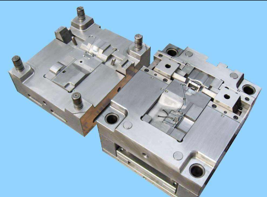
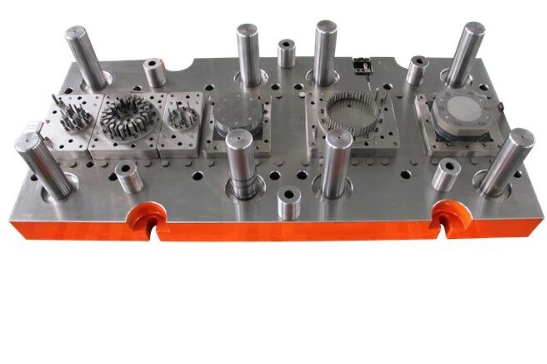
Typy dielov a ich výrobné aplikácie
Výber správny raziaci diel môže rozhodnúť o úspechu alebo neúspechu vášho výrobného projektu. Keďže je k dispozícii niekoľko typov dielov – každý z nich je navrhnutý pre konkrétne aplikácie – pochopenie ich rozdielov vám pomôže optimalizovať výrobnú účinnosť, kontrolovať náklady a dosiahnuť kvalitu súčiastok, ktorú od vás očakávajú vaši zákazníci. Pozrime sa podrobnejšie na štyri hlavné typy dielov používaných v rôznych výrobných odvetviach a preskúmajme, kedy je najvhodnejšie použiť každý z nich.
| Typ matice | Spôsob operácie | Najlepšie použitie | Prispôsobenosť objemu výroby | Úroveň zložitosti |
|---|---|---|---|---|
| Postupná matrica | Postupné stanice vykonávajú operácie, keď sa materiál posúva cez lis | Zložité súčiastky vyžadujúce viacero operácií; automobilové komponenty, ochranné kryty elektronických zariadení | Veľké množstvo (viac ako 100 000 kusov) | Vysoký |
| Zložitý formovací materiál | Viacero operácií dokončených v jednom zdvihu lisu | Jednoduché ploché súčiastky vyžadujúce presnosť; podložky, upevňovacie konzoly, polotovary | Nízky až stredný objem | Nízke až mierne |
| Prekladací nástroj | Súčiastky mechanicky prenášané medzi nezávislými stanicami | Veľké alebo zložité súčiastky; hlboko tažené komponenty, zložité kryty | Stredný až vysoký objem | Vysoký |
| Kombinovaná matrica | Kombinuje rezné a tvarovacie operácie v jednom nástroji | Súčiastky vyžadujúce zároveň vyrezávanie a tvarovanie; poháre, plášte, tažené tvary | Stredný objem | Mierne až vysoké |
Postupné diely pre výrobu veľkých sérií
Ak vyrábate tisíce – alebo milióny – identických súčiastok, postupné diely ponúkajú neprepáranú rýchlosť a účinnosť. Tieto nástroje na kovové štampovanie pracujú prostredníctvom série postupných staníc, pričom každá z nich vykonáva konkrétnu operáciu, keď sa pás materiálu posúva cez lis. Predstavte si to ako montážny pás stlačený do jediného nástroja.
Takto to funguje: cievka plechu sa privádza do lisu a pri každom zdvihu sa materiál posunie dopredu na ďalšiu stanicu. Jedna stanica môže napríklad vyraziť otvory, ďalšia ohnúť lemu, iná odrezať nadbytočný materiál a posledná stanica uvoľní hotový diel. Všetko to prebieha veľmi rýchlo za sebou, často sa tak vyrába niekoľko stoviek dielov za minútu.
Aká je nevýhoda? Vyššie počiatočné náklady na návrh a výrobu nástrojov. Postupné šablóny vyžadujú dôkladné plánovanie a presné technické navrhovanie, aby sa zabezpečilo dokonalé zarovnanie každej stanice. Náklady na jeden diel však pri veľkosériovej výrobe výrazne klesnú, čo robí túto metódu veľmi ekonomickou pre dlhodobé projekty s vysokým objemom výroby. Automobiloví výrobcovia, výrobcovia elektroniky a spotrebičov často používajú postupné šablóny na výrobu komponentov, ako sú upevňovacie konzoly, svorky a konštrukčné posilnenia.
Zložené šablóny na efektívnu viacoperáciu
Potrebujete presnosť bez zložitosti? Zložené diely vykonávajú viacero rezných a prepichovacích operácií v jedinom zdvihu lisu. Na rozdiel od progresívnych dielov, ktoré posúvajú materiál cez jednotlivé stanice, zložené diely vykonávajú všetky operácie súčasne – čo ich robí ideálnymi pre jednoduché ploché súčiastky, kde je najdôležitejšia dodržanie úzkych tolerancií.
Predstavte si výrobu plochej podložky, pri ktorej sa vonkajší priemer aj vnútorný otvor režú v jedinom rýchлом pohybe. Práve takú efektivitu zabezpečujú zložené diely. Keďže sú efektívne z hľadiska využitia materiálu, množstvo odpadu zostáva nízke, čo sa priamo odrazí vo vašich výsledných finančných výsledkoch.
Jednoduchšia štruktúra zložených dielov tiež znamená nižšie náklady na návrh a znížené požiadavky na údržbu v porovnaní s ich progresívnymi protikusmi. Tieto tvárnacie diely však majú obmedzenia – nie sú vhodné pre zložité geometrie alebo súčiastky vyžadujúce viacnásobné ohýbanie alebo taženie. Ak váš projekt vyžaduje vysokopresné ploché súčiastky v stredných množstvách, zložené diely často predstavujú optimálny kompromis medzi nákladmi a funkčnosťou.
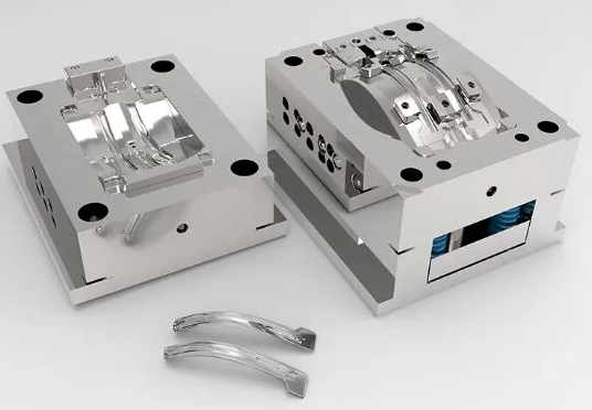
Transferové matrice: flexibilita pre zložité súčiastky
Čo sa stane, ak sú vaše súčiastky príliš veľké alebo zložité na použitie progresívnych dielov? Na scénu vstupuje tvárnenie prenosnými dielmi. Táto metóda mechanicky alebo ručne presúva jednotlivé súčiastky medzi nezávislými tvárnacimi stanicami, čím vám poskytuje väčšiu flexibilitu pri manipulácii a orientácii.
Prenosové tvárnice sa vyznačujú výbornými výsledkami pri výrobe väčších komponentov, ktoré sa do pásikovej formy progresívnej tvárnice nezmestia. Môžu integrovať rôzne operácie – prepichovanie, ohybovanie, taženie a orezávanie – v rámci jedného výrobného cyklu a zároveň umožňujú výrobu zložitejších tvarov a hlbších tažení. Automobilové karosérie, hlboko tažené kryty a zložité štrukturálne komponenty často vyžadujú tento prístup.
Táto flexibilita má svoju cenu. Prevádzkové náklady sú vyššie kvôli zložitým požiadavkám na nastavenie a kvalifikovanej pracovnej sile potrebnej na údržbu. Čas potrebný na nastavenie každého výrobného behu môže byť predĺžený, najmä pri výrobe zložitých dielov. Napriek tomu pre stredné až vysoké výrobné objemy zložitých komponentov poskytujú prenosové tvárnice možnosti, ktoré iné tvárnice a metódy tvárnenia jednoducho nedokážu poskytnúť.
Výber vhodného typu tvárnice
Ako teda výrobcovia rozhodujú medzi týmito možnosťami? Rozhodnutie sa zvyčajne zakladá na štyroch kľúčových faktoroch:
- Zložitosť dielu: Jednoduché ploché diely uprednostňujú kompozitné tvárnice; zložité geometrie vytlačujú výber smerom k progresívnym alebo prenosovým tvárniciam
- Objem výroby: Vysoké objemy ospravedlňujú investíciu do postupných dielov; nižšie počty kusov môžu byť výhodnejšie pri zložených alebo prenosových riešeniach
- Veľkosť dielu: Väčšie súčiastky často vyžadujú prenosové diely; menšie komponenty sa dobre spracúvajú pomocou postupných nástrojov
- Rozpočtové obmedzenia: Zložené diely ponúkajú nižšie počiatočné náklady; postupné diely poskytujú lepšiu ekonomiku na jednotku pri veľkosériovom výrobe
Porozumenie týmto typom dielov a ich aplikáciám tvorí základ úspešných výrobných projektov. Avšak aj najlepšie navrhnutý diel závisí od kvalitných komponentov, ktoré bezproblémovo spolupracujú – čo nás privádza k nevyhnutným stavebným kameňom, ktoré umožňujú každému štampovaciemu dielu fungovať.
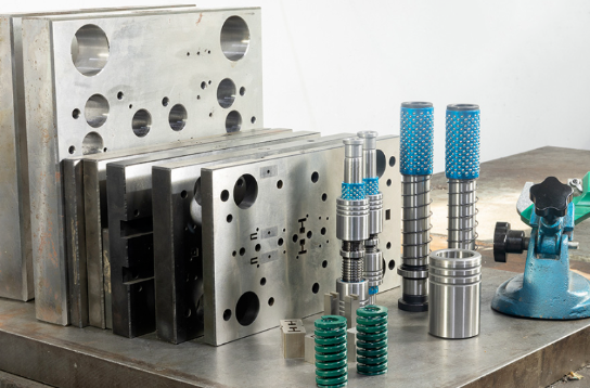
Nevyhnutné komponenty výrobného dielu
Niekedy ste sa zamysleli, čo je vo vnútri tvárnice, ktorá umožňuje premieňať ploché kovové plechy na presné súčiastky? Porozumenie jednotlivým komponentom tvárnice nie je len akademickou záležitosťou – priamo ovplyvňuje vašu schopnosť odstraňovať poruchy, komunikovať so dodávateľmi nástrojov a rozhodovať sa o návrhu a údržbe tvárnice. Pozrime sa podrobnejšie na kritické časti, ktoré v každom lisovacom nástroji spolupracujú.
Kľúčové súčiastky razničky a ich funkcie
A výrobná tvárnica pozostáva z viacerých navzájom prepojených častí , pričom každá z nich plní špecifickú funkciu. Podľa spoločnosti Moeller Precision Tool týchto osem základných komponentov tvárnice tvorí základ väčšiny operácií tvárnenia:
- Výkrojné dosky (podložky/sady): Tieto komponenty slúžia ako základ, na ktorý sa upevňujú ostatné nástrojové časti tvárnice. Zvyčajne sa vyrábajú z ocele alebo ľahkých hliníkových zliatin a udržujú dierovače, tlačné kolíky, pružiny a upevňovacie prvky v presných polohách.
- Vodiaci kolíky a rukávy: Tieto komponenty na nastavenie polohy zabezpečujú presné zosadenie horných a dolných častí dielov. Vyrábajú sa s toleranciami do 0,0001 palca a sú dostupné v prevedeniach s trením alebo s guľovými ložiskami pre rôzne aplikácie.
- Výkrojné píky: Tieto nástroje sú pracovnými koníkmi pri operáciách strihania a tvárnenia: pichové nástroky (punches) stláčajú do plechového materiálu, aby vytvorili otvory alebo ohyby. Majú rôzne tvary hrotov – kruhové, eliptické, štvorcové, šesťuholníkové alebo špeciálne konfigurácie.
- Die Buttons: Tlačidlá (buttons) slúžia ako protikusy k pichovým nástrokom (punches) a poskytujú protilehlú rezaciu hranu. Zvyčajne majú mierne väčší rozmer ako hrot dielového pichového nástroka (o 5–10 % hrúbky materiálu), aby vznikol tzv. „zlom dielového otvoru“ (die break), ktorý je potrebný na čisté strihanie.
- Pružiny die: Tieto vysokosilové tlakové pružiny poskytujú potrebný tlak na udržanie materiálu počas operácií tvárnenia a vyberania (stripping). Najbežnejšie typy sú mechanické vinuté pružiny a dusíkové plynové pružiny.
- Udržiavače matricy: Zámkové (ball-lock), ramenné (shoulder) a trubkové (trumpet head) upevňovače fixujú rezacie a tvárnice komponenty na dielové podrážky (die shoes) a zároveň umožňujú rýchle odstránenie pichových nástrokov (punches) počas údržby.
- Oddeľovacie dosky: Pružinové dosky, ktoré po každej operácii ťahajú alebo odstraňujú kov z rezacích pískov, čím sa zabráni zosadeniu materiálu okolo telies pískov.
- Tlakové podložky: Tieto prvky udržiavajú kov rovný alebo v požadovnom tvare počas rezných a tvarovacích procesov a vyvíjajú silu rovnakú alebo väčšiu ako je sila potrebná na ohyb.
Keď sa die presa cykluje, tieto komponenty musia pracovať v dokonalom súlade. Tlačná doska vyvíja silu cez hornú die kolísku, čím poháňa písky cez materiál, zatiaľ čo odstreďovače a podložky kontrolujú spracovávaný diel. Porozumenie tejto interakcie vám pomôže identifikovať potenciálne problémy ešte predtým, než spôsobia drahé výpadky.
Ako jednotlivé die časti pracujú spoločne
Okrem jednotlivých komponentov každé die pre aplikácie na presy plní štyri základné funkcie. Predstava toho, ako tieto funkcie súvisia, vysvetľuje, prečo je tak dôležitý správny výber a zarovnanie komponentov.
Polohovanie: Predtým, ako začne akékoľvek režanie alebo tvarovanie, musí byť materiál presne umiestnený. Vodiace kolíky vstupujú do predtým vyrazených otvorov, aby zarovnali pás pre následné operácie. Vodidlá obmedzujú bočný pohyb materiálu. Predstavte si, že sa kovový pás zavádza do postupného nástroja – vodiace kolíky zabezpečujú, aby každá stanica dostala materiál presne v správnej polohe a udržiavala tak požadované tolerancie pri výrobe miliónov súčiastok.
Uchytenie: Po presnom umiestnení musí byť materiál pevne upevnený. Tlakové dosky a odstreďovacie dosky pôsobia smerom nadol, čím bránia pohybu materiálu počas režania alebo tvarovania. Uvažujme o operácii ohýbania s posunom: tlaková doska musí vyvinúť silu rovnakú alebo väčšiu než sila potrebná na ohnutie, aby sa kov neposúval. Príliš malý tlak spôsobuje nekonzistentné ohýbanie; príliš veľký tlak môže spôsobiť praskliny v materiáli.
Funkcia: Tu dochádza k transformácii. Razidlové kladivá sa spúšťajú cez materiál do razidlových tlačidiel a vytvárajú otvory alebo strihajú polotovary. Formovacie kladivá tlačia materiál do dutín razidla a vytvárajú ohyby, ťahy alebo reliéfne prvky. Presný vzťah medzi kladivom a tlačidlom – kritická vzdialenosť 5–10 % – určuje kvalitu rezu a životnosť nástroja.
Uvoľnenie: Po pracovnom zdvihu sa musia súčiastky čistou separáciou oddeliť od nástrojov. Pružinové odstreďovače tlačia materiál z kladív po ich stiahnutí. Pri ťahových operáciách vysúvacie kolíky vyhadzujú vytvarované súčiastky z dutín razidla. V prípade neprimeraných uvoľňovacích mechanizmov sa materiál lepí na kladivá, čo spôsobuje poškodenie a výrobné oneskorenia.
Tieto štyri funkcie sa počas výroby neustále opakujú, často stovky krát za minútu. Interakcia medzi jednotlivými súčasťami nástroja určuje nielen kvalitu výrobku, ale aj životnosť nástroja a frekvenciu jeho údržby. Napríklad opotrebované vodidlá umožňujú nesúhlas medzi razníkom a matricou, čím sa zrýchľuje opotrebovanie oboch súčastí a zhoršuje sa kvalita rezu.
Bežné odlišnosti v konfigurácii umožňujú prispôsobiť nástroj rôznym požiadavkám na výrobok. Niektoré nástroje používajú ploché odstreďovacie dosky; iné využívajú tvarované odstreďovacie dosky, ktoré zodpovedajú geometrii výrobku. Ťahové podložky —tiež nazývané uchytenia alebo držiaky polotovarov — riadia tok kovu počas hlbokého ťahania a tak zabraňujú vzniku mäkkých vrások alebo trhliny. Porozumenie týmto odlišnostiam vám pomôže jasne formulovať požiadavky pri zadávaní nového nástroja.
Ak máte pevné pochopenie jednotlivých súčastí nástroja a ich vzájomných interakcií, ste pripravení preskúmať, ako sa tieto prvky spájajú v rámci návrhového a inžinierskeho procesu – kde sa koncepty menia na nástroje pripravené na výrobu.
Návrh a inžiniersky proces výroby dielov
Čo vlastne znamená výroba dielov? Je to oveľa viac než len obrábanie oceľových blokov do požadovaného tvaru. Cesta od náčrtu konceptu až po výrobné nástroje pripravené na sériovú výrobu zahŕňa systematické inžinierske rozhodnutia, pokročilé simulácie a opakované zdokonaľovanie. Porozumenie tomuto procesu vám pomôže stanoviť realistické očakávania, účinne komunikovať s partnermi v oblasti výroby nástrojov a vyhnúť sa drahým chybám, ktoré môžu spomaliť alebo dokonca zastaviť výrobné termíny.
Od náčrtu konceptu po výrobný die
Každý výrobný die začína návrhom súčiastky – avšak tento návrh zvyčajne neprechádza priamo do výroby nástrojov bez podstatnej analýzy a prispôsobenia. Skúsený výrobca dielov preskúma geometriu súčiastky, identifikuje potenciálne výrobné problémy a vyvíja technologický postup, ktorý vyvážene zohľadňuje kvalitu, efektivitu a náklady. Takto sa rozvíja celý pracovný postup návrhu dielov:
- Analýza súčiastky a kontrola DFM: Inžinieri analyzujú návrh súčiastky zákazníka z hľadiska návrhu pre výrobu (DFM). Podľa procesu výroby dielov GOHO Tech je tento kritický prvý krok spojený s pridaním výškových uhlov, úpravou hrúbok stien a definovaním čiar rozdeľovania, aby sa zabezpečila spoľahlivá výroba. Strávenie ďalšieho týždňa na fáze DFM môže ušetriť šesť týždňov na úpravách nástrojov neskôr.
- Vývoj usporiadania procesu: Pri postupných dieloch to znamená vytvorenie rozmiestnenia pásu, ktoré ukazuje, ako sa materiál pohybuje cez jednotlivé stanice. Pri prenosových nástrojoch inžinieri mapujú pohyb súčiastok medzi jednotlivými operáciami. Počas tejto fázy sa venuje pozornosť využitiu materiálu a optimalizácii procesu.
- Simulácia toku materiálu: Predtým, než sa začne rezať akýkoľvek oceľový materiál, inžinieri spustia simulácie toku formovacieho materiálu, ktoré presne predpovedajú správanie materiálu počas formovania. Tieto digitálne analýzy identifikujú potenciálne chyby, ako napríklad zachytenie vzduchu, ztenenie alebo odskok – problémy, ktoré je omnoho lacnejšie vyriešiť softvérovou cestou než v tvrdej ocele.
- Plánovanie tolerancií: Inžinieri stanovujú rozmerové ciele a prípustné odchýlky pre oboje – pre tvárnice aj pre hotové diely. To zahŕňa zohľadnenie odskoku materiálu, tepelnej expanzie a opotrebovania počas predpokladanej životnosti nástroja.
- Podrobný návrh nástroja: Po schválení procesu sa začína podrobné 3D modelovanie. Každá súčiastka – razidla, tlačidlá, odstreďovače, vodidlá – dostáva presné špecifikácie. Návrh musí zohľadniť celý rozsah stavov materiálu, vrátane geometrických aj fyzikálnych vlastností.
- Revízia a schválenie návrhu: Medzifunkčné tímy preverujú dokončený návrh z hľadiska výrobnej uskutočniteľnosti, prístupnosti pri údržbe a bezpečnosti obsluhy. Zmeny vykonané po tomto štádiu sa stávajú stále drahšie.
- Výber a zakúpenie ocele: Na základe objemov výroby a požiadaviek na materiál inžinieri určujú vhodné nástrojové ocele. Pre tvárnice s vysokým výrobným objemom môžu byť potrebné kvalitnejšie značky, napríklad H13, kvôli odolnosti voči teplu; pre aplikácie s nižším výrobným objemom sa môžu použiť ekonomickejšie alternatívy.
- Obrábanie a montáž tvárnice: CNC frézovacie stroje a EDM stroje premieňajú oceľové bloky na presné komponenty. Následne nasleduje tepelné spracovanie, ktoré dosahuje tvrdosť potrebnú na trvanlivosť výroby. Finálna montáž spája všetky komponenty dohromady.
- Skúška a overenie: Dokončená forma prechádza skúšobnými behmi, pri ktorých sa vyrábajú vzorové diely na kontrolu rozmerov. Forma získa schválenie na výrobu až po splnení požiadaviek na schopnosť procesu – zvyčajne minimálna hodnota Ppk 1,67.
Inžinierske aspekty úspešnosti formy
Prečo niektoré formy bez problémov bežia roky, kým iné vyžadujú neustále nastavovanie? Odpoveď často leží v inžinierskych rozhodnutiach prijatých už v ranom štádiu návrhu. Niekoľko faktorov určuje, či bude forma pre výrobu spĺňať očakávania.
Geometria dielu určuje zložitosť: Jednoduché ploché diely s rovnakými prvkami vyžadujú priame nástroje. Pridaním hlbokých tažení, tesných polomerov alebo asymetrických prvkov sa zložitosť rýchlo zvyšuje. Každé ohyb, dierka alebo vydutý detail vyžaduje zodpovedajúce komponenty formy – a každý komponent musí dokonale spolupracovať so svojimi susedmi. Diel s desiatimi prvkami môže vyžadovať progresívnu formu s dvanástimi alebo viacerými stanicami, pričom každá z nich pridáva potenciálne miesta poruchy.
CAE simulácia zníži počet iterácií: Počítačová technická podpora (CAE) premenila výrobu nástrojov a foriem. Moderný softvér na simuláciu tvárnenia predpovedá správanie materiálu s výnimočnou presnosťou a umožňuje inžinierom digitálne testovať viacero návrhových alternatív. Jeden výrobca nedávno v simulácii otestoval tri rôzne návrhy vstupných kanálov a zistil, že len tretia možnosť odstránila zachytený vzduch v kritickom tesniacom priestore. Táto digitálna iterácia trvala jeden deň; zistenie a oprava problému po zostrojení nástroja by trvala týždne.
Medzi aspekty, ktoré je potrebné pri simulácii zohľadniť, patria:
- Analýza ztenčovania materiálu – zvyčajne obmedzená na maximálne 15 % pri konvenčnom tvárnení
- Predikcia pružného návratu pre presné konečné rozmery
- Rozloženie napätia na identifikáciu potenciálnych miest trhlin
- Teplotné účinky pri horúcom tvárnení
Dôležitosť súčtovania tolerancií: Každá súčiastka v obrábacích dieloch prispieva k presnosti konečného výrobku. Vôľne medzi vodičmi, zarovnanie striekača so stlačovacím tlačidlom a rovnosť montážnej plochy sa všetky sčítajú. Skúsené postupy pri kreslení dielov tieto súčty berú do úvahy a zabezpečujú, že aj najhoršie kombinácie stále vytvárajú akceptovateľné súčiastky.
Prístupnosť pre údržbu ovplyvňuje životnosť: Výrobné diely vyžadujú pravidelnú údržbu – brousenie, výmenu komponentov a nastavenie. Konštrukcie, ktoré zakrývajú kritické komponenty pod inými štruktúrami, spôsobujú problémy pri údržbe. Skúsení konštruktéri poskytujú prístupové okná, funkcie rýchlej výmeny a štandardizované komponenty, ktoré zjednodušujú údržbu bez nutnosti odstraňovania dielu z lisu.
Vzťah medzi investíciou do technického návrhu a výkonom tvárnice sleduje jasný vzor: dôkladná analýza na začiatku predchádza drahým problémom v neskorších fázach. Projekt obrábania tvárnice, ktorý je pri navrhovaní ponáhľaný, často vyžaduje celkovo viac hodín na opravy ako projekt, ktorému je vyhradený dostatok času na vývoj. So zvyšujúcimi sa objemmi výroby sa tento vzťah stáva ešte výhodnejším – náklady na rozšírené technické návrhy sa rozprestierajú na väčší počet súčiastok, zároveň však zabraňujú kvalitným problémom, ktoré ovplyvňujú každú vyrobenú jednotku.
Keď je návrh dokončený a technické riešenie overené, pozornosť sa presunie na rozhodnutie, ktoré výrazne ovplyvňuje výkon aj životnosť tvárnice: výber materiálu. Voľba medzi jednotlivými triedami nástrojových ocelí, karbidom a špeciálnymi materiálmi formuje nielen počiatočné investície, ale aj dlhodobé prevádzkové náklady.
Materiály pre diely a kritériá ich výberu
Čo rozdeľuje nástroj, ktorý vydrží desaťročia, od toho, ktorý sa opotrebuje za niekoľko mesiacov? Často je odpoveď závislá od výberu materiálu. Výber správnej oceľovej zliatiny pre nástroj – alebo rozhodnutie, kedy je lepšie použiť karbid – priamo ovplyvňuje životnosť nástroja, frekvenciu údržby a kvalitu každej vyrobenej súčiastky. Toto rozhodnutie však zahŕňa kompromisy, ktoré nie sú na prvý pohľad vždy zrejmé.
| Typ materiálu | Rozsah tvrdosti (HRC) | Odolnosť proti opotrebovaniu | Nákladový faktor | Ideálne aplikácie |
|---|---|---|---|---|
| Nástrojová oceľ D2 | 58-62 | Vysoký | Nízka-stredná | Všeobecné vyrezávanie a tvárnenie; stredné objemy výroby |
| Nástrojová oceľ A2 | 57-62 | Mierne | Nízke, | Aplikácie, kde je dôležitejšia húževnatosť než odolnosť voči opotrebovaniu; operácie s vysokým rizikom nárazu |
| Oceľ na nástroje S7 | 54-58 | Mierne | Stredný | Aplikácie s vysokým nárazovým zaťažením; nástroje vystavené rázovému zaťaženiu |
| Nástrojová oceľ H13 | 44-52 | Mierne | Stredný | Horúce tvárnenie; aplikácie s tepelným cyklovaním |
| M2 rýchlorezná oceľ | 62-65 | Veľmi vysoké | Stredná-Vysoká | Rýchle operácie; reženie abrazívnych materiálov |
| Karbid volfrámu | 70–75 (prepočítané) | Vynikajúcu | Vysoký | Ultra-vysoké objemy výroby; vysoke abrazívne materiály |
Výber nástrojovej ocele pre životnosť matrice
Nástrojové ocele stále zostávajú základnými materiálmi pre väčšinu aplikácií nástrojových diel. Podľa technickej príručky spoločnosti Dayton Lamina sú nástrojové ocele špeciálne navrhnuté na použitie v perforačných a výrobných aplikáciách, pričom rôzne triedy sú optimalizované pre konkrétne požiadavky. Kľúčové je pochopiť, ktoré vlastnosti sú pre vašu konkrétnu operáciu najdôležitejšie.
Hrubičnosť versus odolnosť proti opotrebovaniu: Tu sa nachádza základná kompromisná situácia, s ktorou sa každý návrhár nástrojových diel stretáva. Hrubičnosť – schopnosť odolať sa lupnutiu a trhlinám pri náraze – zvyčajne klesá so zvyšujúcim sa obsahom zliatinových prísad. Zároveň vyšší obsah zliatinových prísad znamená viac karbidov prítomných v oceli, čo výrazne zvyšuje odolnosť proti opotrebovaniu. Obe tieto vlastnosti nemôžete maximalizovať súčasne.
Zvážte kovovú formu používanú na vyrezávanie tenkých plechov z nehrdzavejúcej ocele. Nástrojová oceľ triedy D2 s vysokým obsahom chrómu poskytuje vynikajúcu odolnosť proti opotrebovaniu pre túto abrazívnu aplikáciu. Ak však tá istá forma podlieha významnému nárazovému zaťaženiu, môže dôjsť k jej odlomeniu. Ocele S7 alebo H13 s ich vyššou húževnatosťou tieto nárazy lepšie absorbuje – aj keď sa pri kontinuálnej abrazívnej záťaži opotrebujú rýchlejšie.
Tepelné spracovanie má rovnaký význam ako výber triedy materiálu: Rovnaká oceľová forma sa môže veľmi odlišne správať v závislosti od spôsobu jej tepelného spracovania. Ako uvádzajú metalurgovia z firmy Dayton, aplikácie v oblasti tvárnenia kladú vysoké požiadavky na húževnatosť, čo vyžaduje iné postupy tepelného spracovania ako rezné nástroje vyrobené z rovnakých ocelových tried. Správne predhriatie, vydržiavanie, kalenie a dožíhanie premieňajú surovú oceľ na nástroje pripravené na výrobu. Ak tieto kroky preskočíte alebo ich skrátime, dokonca aj najkvalitnejšie materiály dosiahnu podpriemerný výkon.
Kompresná pevnosť – často podceňovaná – určuje, akú veľkú silu môže komponent vyrobený tvárnením v die vydržať pred deformáciou. Zliatiny ako molibdén a wolfrám zvyšujú túto vlastnosť, čo robí ocele ako M2 vhodnými pre operácie vyžadujúce extrémne tlakové sily pri tvárnení.
Keď má použitie karbidu ekonomický zmysel
Wolframkarbid predstavuje najvyššiu kategóriu materiálov pre tvárnice – a jeho cena tomu zodpovedá. Podľa California Business Journal , karbid môže v abrazívnom prostredí vydržať až 10 až 100-krát dlhšie ako oceľové protikusy. To nie je preklep – správne aplikované karbidové nástroje poskytujú zlepšenie životnosti v poradí veľkosti.
Prečo teda nie každý používa karbid? Niekoľko faktorov obmedzuje jeho použitie:
- Krehkosť: Karbid je extrémne tvrdý, ale chýba mu húževnatosť. Ak upadne karbidový razník na betón, môže sa poškodiť alebo prasknúť. Oceľ by sa len vydlačila.
- Zložitosť výroby: Karbid sa po spekaní nedá obrábať konvenčnými metódami. Tvarovanie vyžaduje brúsenie diamantovými kotúčmi, čo obmedzuje prakticky realizovateľné geometrie a zvyšuje výrobné náklady.
- Počiatočná investícia: Náklady na suroviny sú výrazne vyššie ako u ocele a špeciálne výrobné postupy ďalšie zvyšujú náklady.
Kedy sa investícia do karbidu ospravedlňuje? Výpočet sa zameriava na celkové náklady vlastníctva, nie len na počiatočnú nákupnú cenu. Zvážte napríklad postupnú dišku, ktorá ročne vyrába milióny elektrických kontaktov. Každýkrát, keď zastavíte výrobu kvôli ostreniu alebo výmene opotrebovaných komponentov, stratíte výstup a vzniknú ďalšie pracovné náklady. Karbidový vložok, ktorý stojí päťkrát viac ako jeho oceľový ekvivalent, ale trvá dvadsaťkrát dlhšie, prináša významné čisté úspory a zároveň počas celej svojej predĺženej životnosti zachováva presnejšie tolerancie.
Rozhodnutie ovplyvňuje objem výroby: Aplikácie s vysokým objemom rozkladajú vyššie náklady na karbid na väčší počet dielov, čo robí náklady na jeden kus stále výhodnejšími. Šablóna, ktorá ročne vyrába 500 000 dielov, by karbid pravdepodobne nikdy neoprávnila. Rovnaký návrh pri ročnej výrobe 5 miliónov dielov? Karbid by sa mohol vrátiť už počas prvého roka vďaka zníženému výpadku prevádzky a údržbe.
Aj teplotné faktory v niektorých prípadoch uprednostňujú karbid. Oceľ začína strácať tvrdosť nad teplotou 400–500 °F, zatiaľ čo karbid udržiava svoje vlastnosti až do teplôt 1000 °F alebo vyšších. Vysokorýchlostné operácie generujúce trením teplo alebo procesy horúcej tvárnenia často vyžadujú tepelnú stabilitu karbidu.
Mnoho výrobcov uprednostňuje hybridný prístup: používa vložky z karbidu v miestach s vysokým opotrebovaním, zatiaľ čo väčšinu šablóny vyrába z nástrojovej ocele. Tento prístup využíva výhody karbidu v odolnosti proti opotrebovaniu tam, kde je to najdôležitejšie, a zároveň kontroluje celkové investície do nástrojov.
Keď výber materiálu tvorí základ pre výkon nástroja, ďalším kľúčovým aspektom pri optimalizácii vašich výrobných operácií je pochopenie toho, ako rôzne metódy rezných a tvárnicích operácií tieto materiály využívajú.
Vysvetlenie rezných a tvárnicích operácií nástrojmi
Čo je to rezanie nástrojom a prečo výrobcovia pre rôzne aplikácie vyberajú rôzne metódy? Pochopte metódy rezania nástrojom a tvárnicích operácií, aby ste mohli priradiť správny prístup k vašim výrobným požiadavkám – či už vyrábate milióny etikiet alebo tvarujete karosérie automobilov. Preskúmajme kľúčové rozdiely, ktoré formujú tieto dôležité výrobné rozhodnutia.
Porovnanie metód rezania nástrojom
V základe ide o vystrihované diely – presne tvarované kúsky, ktoré vzniknú, keď strihový nástroj (die) oddeľuje materiál do požadovaných tvarov. Predstavte si pekáčik na sušienky, ktorý stlačí cez cesto – to je v podstate to, čo robí stroj na vystrihovanie (die cutter), hoci pracuje s materiálmi od papiera až po kov s veľkou hrúbkou. Dva hlavné prístupy k strojovému vystrihovaniu sa zásadne líšia podľa potrieb výroby.
Plošné frézovanie umiestni materiál na plochý povrch, pričom plošná doska (platen) so strihovým nástrojom (die) sa pohybuje zvislo, aby vykonala rezy. Podľa Technického porovnania spoločnosti Rhyguan stroje s plošnou doskou efektívne spracúvajú hrubšie materiály a umožňujú použitie materiálu vo forme plátov. Nevýhodou je pomalší výrobný tempo, čo tento prístup robí vhodným pre menšie výrobné dávky.
Rotačné rezanie dielov prerába materiál neustále medzi valcovým dielom a anvilovým valčekom. Pri rotácii valcov režúce hrany stláčajú materiál proti anvilu, čím vznikajú čisté rezy alebo perforácie. Táto nepretržitá prevádzka zabezpečuje výrazne vyšší výkon pre priemyselné aplikácie strojov na vystrihovanie pomocou dielov.
- Výkon výroby: Rotačné systémy sa vyznačujú výbornými výsledkami pri veľkých sériách; plošné metódy sú vhodnejšie pre menšie dávky.
- Hrúbka materiálu: Plošné diely spracúvajú hrubší materiál; rotačné diely dosahujú najlepšie výsledky s tenším, pružným materiálom.
- Presnosť: Rotačné vystrihovacie stroje dosahujú úzke tolerancie a kontrolujú výstrednosť medzi valcami v minimálnych rozmedziach.
- Možnosť povrchového rezu (kiss cutting): Rotačné systémy umožňujú povrchový rez pre etikety a nálepky; plošné stroje to zvyčajne nedokážu.
- Náklady na nástroje: Náklady na plošné diely sú nižšie a ich vývoj je rýchlejší; rotačné diely vyžadujú vyššie investície, avšak pri veľkých objemoch znížia jednotkové náklady.
- Formát materiálu: Plošné systémy pracujú s listovým materiálom; rotačné systémy vyžadujú spojitý materiál z rolky.
Vystrihovacie stroje pre kovové aplikácie zvyčajne využívajú ploché (flatbed) konfigurácie pre materiály s veľkou hrúbkou, zatiaľ čo výrobcovia etikiet a obalov uprednostňujú rotačné systémy kvôli ich výhodám v rýchlosti. Váš výber závisí od typu materiálu, objemu výroby a požiadaviek na presnosť.
Štampovacie operácie a požiadavky na lisovacie stroje
Okrem strihania šablóny vykonávajú v priemyselnej výrobe tri odlišné kategórie operácií: strihanie, tvárnenie a ťahanie. Každá z týchto kategórií kladie iné požiadavky na lisovacie zariadenia a návrh nástrojov.
Rezacie operácie zahŕňajú vyraďovanie (blanking), vŕtanie otvorov (piercing), orezávanie (trimming) a strihanie (shearing). Tieto operácie oddelujú materiál pomocou strihacích síl – v podstate prebieha pretlačenie razidla cez materiál do otvoru matrice. Automobilový priemysel sa pri výrobe upevňovacích prvkov, posilovacích prvkov a štrukturálnych komponentov s presnou kvalitou okrajov spolieha na strihacie operácie.
Tvárnenie ohýbať, natiahnuť alebo stlačiť materiál bez jeho rozdeľovania. Ohýbanie vytvára lemy a kanály; reliéfne tlačenie vytvára vystupujúce povrchové prvky; kalibrovanie aplikuje extrémny tlak na dosiahnutie jemných detailov a rozmerného presného výsledku. Výrobcovia elektroniky využívajú tvárenie rozsiahlo pre krytia konektorov a chladiče.
Ťahové operácie premeniť ploché polotovary na trojrozmerné tvary – poháre, plechovky a zložité krytia. Spotrebné tovar, ako sú kuchynské pomôcky, obaly nápojov a komponenty spotrebičov, sa pri výrobe nepretržitých a štrukturálne pevných krytov opierajú o proces hlbokého taženia.
Výpočet správnej tonáže lisu zabezpečuje úspešné vykonanie operácií bez poškodenia nástrojov alebo výroby chybných dielov. Podľa spoločnosti Dayton Rogers je základný vzorec pre výpočet tonáže nasledovný:
T = P × Th × C
Kde T predstavuje požadovaný tlak v tonách, P je obvod rezu v palcoch, Th je hrúbka materiálu a C je materiálová konštanta (strihová pevnosť delená 2000). Napríklad rez s obvodom 12 palcov v polotvrdom studenoväčovanom ocelovom plechu s hrúbkou 0,050" vyžaduje: 12 × 0,050 × 32 = 19,2 tony.
Materiálové konštanty sa výrazne líšia – mäkké hliník používa hodnotu 11, zatiaľ čo polotvrdá nehrdzavejúca oceľ vyžaduje 50. Nedostatočný odhad potrebného tlaku spôsobuje neúplné rezy a zrýchlené opotrebovanie nástrojov; nadmerný odhad naopak plýtvá energiou a nadmierne zaťažuje zariadenie.
Pri rýchlosti lisu sa musí dosiahnuť rovnováha medzi výkonnosťou a kvalitou. Vyššie rýchlosti zvyšujú výrobný výkon, avšak zároveň generujú viac tepla prostredníctvom trenia, čo môže ovplyvniť vlastnosti materiálu a životnosť nástrojov. Komplexné tvárné operácie zvyčajne vyžadujú nižšie rýchlosti, aby sa umožnil prietok materiálu bez jeho trhania. Výrobní inžinieri optimalizujú tieto parametre na základe špecifických požiadaviek na súčiastku, vlastností materiálu a cieľov kvality.
Porozumenie týmto prevádzkovým rozdielom vám pomôže jasne formulovať požiadavky pri zakúpení nástrojov. Avšak aj dokonale navrhnuté a prevádzkované tvary vyžadujú neustálu pozornosť – čo nás privádza k údržbovým postupom, ktoré zabezpečujú hladký priebeh výroby.
Údržba a optimalizácia životnosti tvárničiek
Aký je rozdiel medzi tvarom, ktorý vyrobí milióny kvalitných súčiastok, a tvarom, ktorý neočakávane zlyhá a zastaví vašu výrobnú linku? Často ide o otázku údržby. Podľa JVM Manufacturing môže zlá údržba nástrojov a tvarov výrazne ovplyvniť kvalitu a efektívnosť výroby – zatiaľ čo neočakávané poruchy narušujú plánovanie a spôsobujú nákladné núdzové situácie. Porozumenie tomu, ako sa výrobné tvary porúšajú, a predchádzanie týmto poruchám ešte pred ich výskytom, má priamy vplyv na vaše konečné výsledky.
Preventívna údržba na predĺženie životnosti tvarov
Uvažujte o údržbe nástrojov ako o údržbe vozidla. Nepočkali by ste, kým sa váš motor zasekne, aby ste vymenili olej. Rovnaká logika sa uplatňuje aj pri strojových nástrojoch – pravidelná starostlivosť predchádza katastrofálnym poruchám a výrazne predlžuje ich životnosť. Takto vyzerá účinný program údržby:
- Vykonávajte pravidelné vizuálne prehliadky: Skontrolujte pracovné povrchy a rezné hrany na príznaky opotrebovania, trhliny alebo poškodenia pred i po výrobných cykloch. Hľadajte hrianky, škrabance alebo zmeny farby, ktoré naznačujú vznikajúce problémy.
- Použiť vhodné mazanie: Znížte trenie medzi pohybujúcimi sa povrchmi, aby ste zabránili hromadeniu tepla a únavy materiálu. Rôzne operácie vyžadujú špecifické typy mazív – oleje pre vysokorýchlostné aplikácie, mazivá pre ložiská a kĺby a tuhé mazivá pre extrémne teploty.
- Dodržiavajte plán brúsenia: Procesy brúsenia a broušenia obnovujú pôvodnú geometriu a ostrosť rezných hrán. Pravidelné obnovovanie udržiava presnosť rozmerov a kvalitu povrchov, ktoré poškodené hrany nedokážu dosiahnuť.
- Skontrolujte zarovnanie a kalibráciu: Uistite sa, že horná a dolná časť dielového nástroja presne sedia. Nesprávne zarovnanie zrýchľuje opotrebovanie razníkov, tlačidiel a vodidlí a zároveň zhoršuje kvalitu výrobkov.
- Používajte vhodné podložky: Správne použitie podložiek udržiava požadované vzdialenosti a polohovú presnosť. Nesprávna voľba podložiek vedie k nerovnomerným rezom, nadmernému opotrebovaniu a potenciálnemu poškodeniu nástroja.
- Používajte pokročilé metódy kontroly: Ultrazvuková skúška a magnetoprašková skúška odhaľujú podpovrchové chyby, ktoré nie je možné zistiť vizuálnou kontrolou, a tak zachytia problémy ešte pred ich prejavením ako poruchy.
Plánovanie má rovnaký význam ako samotné úlohy. Preventívna údržba počas plánovaných výpadkov zabraňuje prerušeniam výroby. Podľa Výskumu Vacaero o analýze porúch mnohé praskliny, ktoré sa pripisujú brúseniu, v skutočnosti vznikajú v predchádzajúcich výrobných krokoch – čo zdôrazňuje, prečo systematická údržba odhaľuje problémy, ktoré jednotlivé kontrolné prehliadky vynechajú.
Rané príznaky zlyhania dielového nástroja
Väčšinou sa tvárnice nezlyhnú náhle, bez varovania. Získanie schopnosti rozpoznať skoré príznaky vám umožní vyriešiť menšie problémy, kým sa nezmenia na núdzové situácie, ktoré zastavia výrobu. Medzi bežné spôsoby poruchy v odvetví výroby tvárníc patria:
Obliečenie: Postupná strata materiálu na rezacích hranách a tvarovacích plochách. Všimnete si, že na výrobu dielov je potrebná väčšia sila, hrany sa stávajú menej ostrohranné alebo rozmery sa posúvajú mimo tolerancií. Opotrebovanie sa zrýchľuje pri spracovaní abrazívnych materiálov alebo pri prevádzke tvárníc bez dostatočného mazania.
Čipovanie: Odlomenie malých častí z rezacích hrán – často spôsobené nadmernou tvrdosťou, nárazovým zaťažením alebo vniknutím cudzieho materiálu do tvárnice. Dbajte na nepravidelnú kvalitu hrán vytlačených dielov alebo na nezvyčajné zvuky počas prevádzky lisu.
Vyrobené: Premiestňovanie materiálu medzi povrchom tvárnice a povrchom spracovávaného dielu, čo spôsobuje drsné miesta a problémy s adhéziou. Zálievanie (galling) zvyčajne signalizuje nedostatočné mazanie, nadmerný tlak alebo nekompatibilitu materiálov. Na dieloch sa môžu objaviť škrabance, poškodenia od trenia alebo prilnavosť materiálu.
Nesúosvosť: Keď sa horné a dolné diely tvárnice už nepresne prispôsobia, budete pozorovať nerovnomerné rezy, nekonzistentné ohyby alebo rýchle opotrebovanie vodidiel a vložiek. Tvárnice, ktoré trpia posunom zariadenia, vyrábajú súčiastky s rozdielnymi rozmermi počas celej výrobnej série.
Riešenie problémov začína systematickým pozorovaním. Ak sa u súčiastok náhle objavia kvalitné problémy, skontrolujte nedávne zmeny – nové šarže materiálu, upravené nastavenia lisu alebo vykonanú údržbu. Farba povrchu trhliny (tzv. temperová farba) naznačuje vystavenie nadmernému teplu, čo môže svedčiť o problémoch pri brúsení alebo prevádzke. Škála vo vnútri trhliny ukazuje na problémy vzniknuté počas tepelného spracovania, nie počas prevádzky.
Prostredie, v ktorom prebieha spracovanie tvárnic, tiež ovplyvňuje ich životnosť. Kontrola teploty, vlhkosti a kontaminácie chráni nielen nástroje, ale aj kvalitu vyrábaných súčiastok. Operátori, ktorí sú vyškolení na rozpoznávanie varovných signálov – nezvyčajných zvukov, zvýšených požiadaviek na silu alebo vizuálnych zmien – predstavujú vašu prvú obrannú líniu proti neočakávaným poruchám.
Investovanie do údržby prináša výhody, ktoré siahajú ďaleko za predchádzanie poruchám. Dobrým údržbou vyrobené tvary produkujú počas celej svojej životnosti konzistentné diely, čím sa znížia množstvá odpadu a náklady súvisiace s kvalitou. Táto konzistencia sa priamo prejavuje v uspokojenosti zákazníkov a predvídateľnej výrobe – čo nás privádza k nákladovým faktorom, ktoré ovplyvňujú rozhodnutia o výrobe tvarov.
Faktory nákladov a ekonomické úvahy
Koľko by ste mali investovať do výroby tvarov a kedy sa táto investícia vráti? Tieto otázky nedávajú spávať manažérom nákupu a inžinierom výroby – a to z dobrého dôvodu. Rozdiel medzi rozumnými investíciami do nástrojov a drahými chybami často závisí od pochopenia celkového nákladového obrazu, nie len od čísla uvedeného v ponuke.
Tu je nepríjemná pravda: zameranie sa výlučne na počiatočnú cenu je nákladnou formou krátkozrakosti ako bludný les, lacná ponúka vyzerá lákavo, ale nakoniec môže viesť váš podnik k skrytým nákladom spôsobeným vysokými nákladmi na údržbu, výrobnými zátekami a problémami s kvalitou. Pozrime sa podrobnejšie na to, čo skutočne ovplyvňuje náklady na výrobu dielov a ako strategicky posúdiť svoje investície.
Výpočet návratnosti investície do dielov
Celkové náklady na vlastníctvo (TCO) by mali nahradiť cenu nákupu ako vašu hlavnú metriku hodnotenia. Počiatočná ponúka predstavuje len vrchol ľadovca – pod povrchom sa skrývajú obrovské, projektovo určujúce náklady. Profesionálna štruktúra nákladov na výrobu dielov zvyčajne zahŕňa:
- Návrh a inžinierstvo: Intelektuálny kapitál skúsených inžinierov, vrátane analýzy dizajnu pre výrobu (DFM), simulácií a optimalizácie
- Materiálové náklady: Nástrojovú oceľ, karbidové vložky a špeciálne zliatiny, ktoré tvoria „kostru“ dielu
- Obrábanie a výroba: CNC operácie, elektroerozívne obrábanie (EDM), brúsenie a tepelné spracovanie, ktoré premieňajú surovú oceľ na presné komponenty
- Montáž a skúšobná prevádzka: Montáž komponentov, skúšobné behy a overenie výrobnej schopnosti
- Nepriame náklady a logistika: Manažment projektov, balenie, preprava a príslušné dane
Avšak explicitné náklady vyprávajú len časť príbehu. Skryté výdavky sa objavujú počas výroby a prevádzky a nakoniec formujú vašu skutočnú návratnosť investícií. Rozhodnutie o výrobe lacnej nástrojovej výbavy často signalizuje kompromisy v kvalite ocele, optimalizácii návrhu, presnosti obrábania alebo tepelnom spracovaní. Akékoľvek úspory dosiahnuté na začiatku sa takmer nevyhnutne vrátia – a to násobne – počas výroby.
Zvážte tieto skryté faktory nákladov, ktoré lacná nástrojová výbava spôsobuje:
- Častá údržba: Chybný štrukturálny návrh alebo nedostatočná pevnosť spôsobujú opakujúce sa poruchy, čím sa výrobné tímy dostávajú do nákladných cyklov núteného riešenia kríz
- Problémy s kvalitou: Nízkokvalitné materiály produkujú súčiastky, ktoré rýchlejšie vychádzajú z tolerancií, čo zvyšuje mieru odpadu a stŕža si sťažnosti zákazníkov
- Oneskorenia výroby: Spolupráca s neprofesionálnymi dodávateľmi vyžaduje neúmerne veľa času od vašich inžinierskych a nákupných tímov
- Náklady na opravy: Ak sa chyby v návrhu objavia až po uvedení výrobku na trh, úprava dielov pre sériovú výrobu môže mať katastrofálne dôsledky
Kedy výroba dielov pre tvárnenie má ekonomický zmysel
Vzťah medzi výrobou dielov pre tvárnenie a alternatívnymi technológiami – najmä reznými lasermi – ilustruje, kedy investícia do dielov pre tvárnenie prináša vyššiu hodnotu. Podľa analýzy výrobných nákladov od Hoteanu sa bod zvratu výrazne odvíja od objemu výroby.
Pre dávky pod 3 000 kusov rezný laser zvyčajne umožňuje zníženie nákladov o 40 % v porovnaní s tvárnou výrobou, keďže sa eliminujú náklady na nástroje vo výške viac ako 15 000 USD. Ekonomika je priama: náklady na nástroje pre tvárnú výrobu sa pohybujú v rozmedzí od 10 000 do 50 000 USD a ich výrobná doba trvá 4–8 týždňov, čo robí tvárnú výrobu neekonomickou pre malé objednávky. Pri týchto menších dávkach sú priemerné náklady na rezanie laserom 8,50 USD za kus oproti 14,20 USD za kus pri tvárnej výrobe.
Avšak rovnica sa pri vyšších objemoch výrazne mení. Zvážte, ako sa náklady na nástroje pre tvárnú výrobu rozkladajú:
| Objem výroby | Vplyv nákladov na nástroje na jednotku | Obľúbená metóda | Hlavná výhoda |
|---|---|---|---|
| Menej ako 1 000 kusov | viac ako 15,00 USD za súčiastku | Laserového rezania | Žiadna investícia do nástrojov; dodacia lehota 24 hodín |
| 1 000–3 000 kusov | 5,00–15,00 USD za súčiastku | Rezanie laserom (zvyčajne) | Rýchlejší výstup na trh; flexibilita návrhu |
| 3 000–10 000 kusov | 1,50–5,00 USD za súčiastku | Posúdiť obe možnosti | Závisí od zložitosti súčiastky a požiadaviek na presnosť |
| 10 000–50 000 kusov | 0,30–1,50 USD za súčiastku | Výroba nástrojov | Nižšie náklady na jednu súčiastku; konzistentná kvalita |
| 50 000+ kusov | Menej ako 0,30 USD za súčiastku | Výroba nástrojov | Výrazná cenová výhoda; rýchlosť výroby |
Okrem objemu existuje niekoľko ďalších faktorov, ktoré vedú k rozhodnutiu v prospech výroby dielov aj pri stredných objemoch:
- Požiadavky na presnosť: Výrazovanie dosahuje tolerancie ±0,3 mm; laserové rezanie dosahuje tolerancie ±0,1 mm. Pre aplikácie vyžadujúce veľmi úzke tolerancie môže byť laserové rezanie stále preferované bez ohľadu na objem výroby.
- Zložitosť dielu: Hlboké vytiahnutia, zložité ohyby a viacstaničné operácie uprednostňujú postupné výrazovacie príslušenstvo.
- Hrúbka materiálu: Výrazovanie spracováva hrubšie materiály ekonomickejšie ako laserové rezanie pre väčšinu aplikácií.
- Požiadavky na povrchovú úpravu: Tvarovanie do dielov zabezpečuje rovnaký povrchový kvalifikátor na všetkých súčiastkach; laserové rezanie ponecháva tepelne ovplyvnené zóny.
Priemysel výroby dielov sa čoraz viac orientuje na modulárne prístupy, aby sa zvýšila návratnosť investícií (ROI). Návrh formovacích nástrojov so štandardnými základmi a vymeniteľnými jadrovými vložkami znamená, že pre budúce odvodené verzie výrobkov je potrebná len minimálna investícia do nových vložiek namiesto úplnej výmeny celého formovacieho nástroja. Táto stratégia maximalizuje dlhodobú hodnotu vašich výrobných nástrojových aktív.
Chytrá nákupná stratégia znamená tiež prispôsobenie triedy životnosti dielov skutočným výrobným potrebám. Použitie dielu triedy 101, ktoré je určené na 1 milión výstrelkov, pri projekte s objemom 50 000 kusov predstavuje plýtvanie zdrojmi. Naopak, použitie dielu triedy 104 v rámci výroby milióna kusov spôsobuje neustále výpadky a poruchy kvality. Pri žiadosti o ponuku (RFQ) špecifikujte primeranú nástrojovú triedu SPI, aby ste sa vyhli nadmerným investíciám – alebo nedostatočnému technickému návrhu.
Porozumenie týmto nákladovým dynamikám vás mení z pasívneho porovnávača cien na strategického rozhodovateľa. Dokonca aj dokonalá analýza nákladov však má malú hodnotu bez schopného výrobného partnera, ktorý by váš projekt realizoval – čo nás privádza k posudzovaniu a výbere dodávateľov výroby dielov.
Výber dodávateľa výroby dielov
Zvládli ste typy nástrojov, pochopili ste výber materiálov a vypočítali ste svoj ROI. Teraz prichádza rozhodnutie, ktoré určuje, či sa všetky tieto znalosti premenia na úspech výroby: výber správneho výrobcu nástrojov. Akú hodnotu má odbornosť v oblasti nástrojov a tvárnic, ak Váš partner nedokáže splniť svoje sľuby? Výber medzi spoločnosťami vyrábajúcimi tvárnice vyžaduje systematické posúdenie – nie len porovnávanie ponúk, ale aj posúdenie schopností, ktoré predpovedajú dlhodobý výkon.
Riziká sú významné. Podľa sprievodcu LMC Industries pre výber partnerov môže výber správneho partnera v oblasti zmluvnej výroby rozhodnúť o úspechu alebo neúspechu podniku. Výrobca, ktorý sa stane dôverovaným poradcom – nie len dodávateľom – pomáha optimalizovať návrh výrobku, zefektívniť výrobu a zlepšiť cenovú efektívnosť. Preskúmajme, čo od seba oddeľuje vynikajúcich partnerov v oblasti výroby nástrojov a tvárnic od uspokojivých dodávateľov.
Posudzovanie schopností výroby tvárnic
Keď pochopíte nástroj a význam tvárnice v praktických termínoch, uvedomíte si, že schopnosti sa rozširujú ďaleko za rámec obrábacích možností. Skutočne kvalifikovaný tvárnik prináša inžiniersku hĺbku, flexibilitu výroby a odborné znalosti v oblasti riešenia problémov, ktoré predchádzajú vzniku problémov, kým by mohli ovplyvniť váš časový plán.
- Overte skúsenosti v konkrétnej odvetve: Spracoval výrobca projekty podobné vašim? Tvárnik s overenými skúsenosťami z automobilového priemyslu pozná špecifické výzvy, ako sú úzke tolerancie, požiadavky na vysoké výrobné objemy a špecifikácie výrobcov originálnych zariadení (OEM). Požiadajte o prípadové štúdie alebo referencie z vašej odvetvia – výrobcovia s relevantnými referenciami výrazne znížia riziká projektu.
- Posúďte inžinierske schopnosti: Môžu optimalizovať návrh vašej súčiastky z hľadiska výrobnosti? Hľadajte možnosti CAE simulácie, ktoré predpovedajú správanie materiálu ešte pred obrábaním ocele. Odborní výrobcovia predvídajú výzvy, ako je deformácia kovu a odskok, a príslušne upravujú návrhy. Silné inžinierske tímy vyvážia funkčné požiadavky s efektívnosťou výroby.
- Posúďte výrobnú kapacitu a škálovateľnosť: Dokážu spĺňať súčasné požiadavky a rásť spolu s vami? Posúďte, či ich infraštruktúra zvláda aj výrobu prototypových sérií, aj výrobu vo veľkom objeme. Partner, ktorý sa prispôsobuje meniacim sa požiadavkám, vám poskytne flexibilitu pri vývoji vášho podnikania.
- Preskúmajte systémy kontroly kvality: Aké postupy kontrol zabezpečujú konzistentný výstup? Spýtajte sa na testovanie pomocou súradnicovej meracej strojnice (CMM), štatistickú reguláciu výrobného procesu a systémy sledovania chýb. Spoľahliví partneri vedú podrobné záznamy o kontrolách kvality a použitých materiáloch, aby bola zaručená úplná sledovateľnosť.
- Potvrďte komunikačné postupy: Poskytujú pravidelné aktualizácie a správy o pokročilosti v reálnom čase? Účinné partnerstvá závisia od transparentnej komunikácie počas celého výrobného procesu. Uistite sa, že potenciálni partneri zodpovedajú vašim očakávaniam týkajúcim sa spolupráce a reaktivity.
- Preskúmajte transparentnosť nákladov: Je ich cenová štruktúra podrobnou a obsahuje všetky súvisiace náklady? Dôveryhodný výrobca poskytuje komplexné rozpisy – náklady na nástroje, materiály, prepravu a potenciálne náklady na úpravy – bez skrytých prekvapení, ktoré by ovplyvnili váš rozpočet.
- Zvážte umiestnenie a dodací čas: Ako ovplyvňuje ich umiestnenie dodacie harmonogramy a náklady na prepravu? Blízkosť ponúka výhody pri rýchlej realizácii, hoci partneri mimo krajiny môžu ponúknuť cenové výhody vyvážené dlhšími dodacími časmi a zložitejšou logistikou.
Kvalitné štandardy, ktoré majú význam
Certifikáty nie sú len ozdobou na stene – predstavujú overené záväzky k systematickému manažmentu kvality. Pri hodnotení dodávateľov priemyselných nástrojov, dielov a inžinierskych služieb požiadavky na certifikáciu signalizujú operačnú zrelosť a orientáciu na zákazníka.
ISO 9001 stanovuje základ a preukazuje dokumentované systémy manažmentu kvality s procesmi neustáleho zlepšovania. Avšak pre automobilové aplikácie potrebujete viac.
IATF 16949 sa opiera o normu ISO 9001 a dopĺňa ju požiadavkami špecifickými pre automobilový priemysel. Podľa Prehľad certifikácií spoločnosti Abbott Tool , tento štandard sa zameriava na vývoj systémov manažmentu kvality, ktoré zabezpečujú neustále zlepšovanie s dôrazom na prevenciu chýb a zníženie odchýlok a odpadu v celom dodávateľskom reťazci. Spoločnosť musí najprv získať certifikát ISO 9001, aby mohla implementovať štandard IATF 16949 – dodatočné požiadavky preukazujú záväzok voči excelentnosti v automobilovom priemysle.
Okrem certifikácií vyhodnoťte aj percentuálny podiel schválení pri prvej skúške a schopnosti rýchleho výrobného prechodu na prototypy. Partneri, ktorí dosahujú podiel schválení pri prvej skúške 93 % alebo vyšší, preukazujú inžiniersku presnosť, ktorá znižuje nákladné opakované iterácie. Schopnosti rýchleho prototypovania – niektorí výrobcovia dodávajú vzorky už za 5 dní – zrýchľujú váš vývojový časový plán a umožňujú rýchlejší vstup na trh.
Pre čitateľov, ktorí preskúmavajú možnosti automobilových tvárnic na tvárnenie kovov, Komplexné schopnosti návrhu a výroby foriem spoločnosti Shaoyi predstavujú to, čo kvalifikovaní partneri ponúkajú: certifikáciu IATF 16949, pokročilé CAE simulácie pre bezchybné výsledky, rýchle prototypovanie a vysoký podiel schválení pri prvej skúške. Ich inžiniersky tím dodáva nákladovo efektívne nástroje prispôsobené štandardom výrobcov automobilov – presne tú kombináciu schopností, ktorá je potrebná pre úspešné partnerstvá v oblasti výroby nástrojov a tvárnic.
Nezabudnite, že partner výroby dielov by mal fungovať ako rozšírenie vášho tímu – zaujíma ho váš úspech, nie len splnenie objednávok. Systematickou evaluáciou skúseností, kapacít, systémov kvality a komunikačných postupov zabezpečíte úspech vašich projektov výroby už od prvej vyrobeného dielu.
Často kladené otázky o dieloch v priemyselnej výrobe
1. Čo je to die (diel) v továrni?
Diel je špeciálny presný nástroj používaný v továrňach na režanie, tvarovanie alebo tvorbu materiálov, ako sú kov, plast alebo gumu, do konkrétnych tvarov prostredníctvom pôsobiacej sily. Diely fungujú podobne ako formy a plnia štyri základné funkcie: umiestnenie materiálu, upnutie materiálu na mieste, spracovanie (režanie alebo tvarovanie) a uvoľnenie hotového dielu. Umožňujú sériovú výrobu identických komponentov s výnimočnou konzistenciou, často sa vyrába tisíce alebo milióny dielov predtým, než je potrebná údržba.
2. Prečo sa tomu hovorí výroba dielov?
Výraz „die“ (výstupná forma) pochádza z latinského slova „datum“, čo znamená „niečo dané“ alebo „nastavené“, čo odráža jeho úlohu ako pevného nástroja používaného na tvarovanie materiálov do požadovaných tvarov. Výroba výstupných foriem sa vzťahuje na celý proces návrhu, inžinierskeho riešenia a výroby týchto špeciálnych nástrojov. Tento proces zahŕňa analýzu súčiastky, simuláciu toku materiálu, plánovanie tolerancií, podrobný návrh, výber ocele, presné obrábanie, tepelné spracovanie, montáž a overovacie skúšky, aby sa vytvorili nástroje pripravené na výrobu.
3. Aké sú hlavné typy výstupných foriem používaných v výrobe?
Štyri hlavné typy sú postupné diely, zložené diely, prenosové diely a kombinované diely. Postupné diely využívajú postupné stanice na výrobu komplexných súčiastok vo veľkom množstve. Zložené diely vykonávajú viacero operácií v jednom zdvihu pre jednoduchšie ploché súčiastky. Prenosové diely mechanicky presúvajú súčiastky medzi nezávislými stanicami pre veľké alebo zložité komponenty. Kombinované diely spájajú rezné a tvárné operácie pre súčiastky, ktoré vyžadujú nielen vyrezávanie, ale aj tvarovanie, napríklad poháre a tažené plášte.
4. Ako zistím, či je výroba dielov vhodná pre môj projekt?
Výroba dielov z oceľových foriem zvyčajne má ekonomický zmysel pri výrobných objemoch presahujúcich 3 000–10 000 kusov, keď sa náklady na výrobu nástrojov efektívne odpisujú. Pri objemoch pod 3 000 kusov často poskytuje laserové rezanie zníženie nákladov o 40 % vylúčením investície do nástrojov vo výške 15 000 USD a viac. Zvážte výrobu dielov z oceľových foriem, ak potrebujete konzistentnú kvalitu pri veľkých výrobných objemoch, zložité operácie tvárnenia, ako sú hlboké ťahy, hrubšie materiály alebo špecifické požiadavky na povrchovú úpravu, ktoré laserové rezanie nedokáže splniť.
5. Čo by som mal hľadať pri výbere partnera pre výrobu dielov z oceľových foriem?
Posúďte odborné skúsenosti v danej odvetví, inžinierske schopnosti vrátane CAE simulácií, výrobnú kapacitu a škálovateľnosť, systémy kontroly kvality s certifikáciami ako napr. IATF 16949, komunikačné postupy, transparentnosť nákladov a dodacie lehoty. Hľadajte partnerov s vysokou mierou schválenia pri prvej skúške (93 % a viac) a schopnosťou rýchleho prototypovania. Kvalifikovaní partneri, ako napr. Shaoyi, ponúkajú komplexný návrh foriem, pokročilé simulácie na dosiahnutie bezchybných výsledkov a inžinierske tímy, ktoré optimalizujú návrhy z hľadiska výrobnosti.