 Serii mici, standarde ridicate. Serviciul nostru de prototipare rapidă face validarea mai rapidă și mai ușoară —

Selectarea seturilor de matrițe de ambutaj: Potrivește-le cu presa, materialul și obiectivele de producție
Ce este un set de matrițe pentru ambutisare și cum funcționează
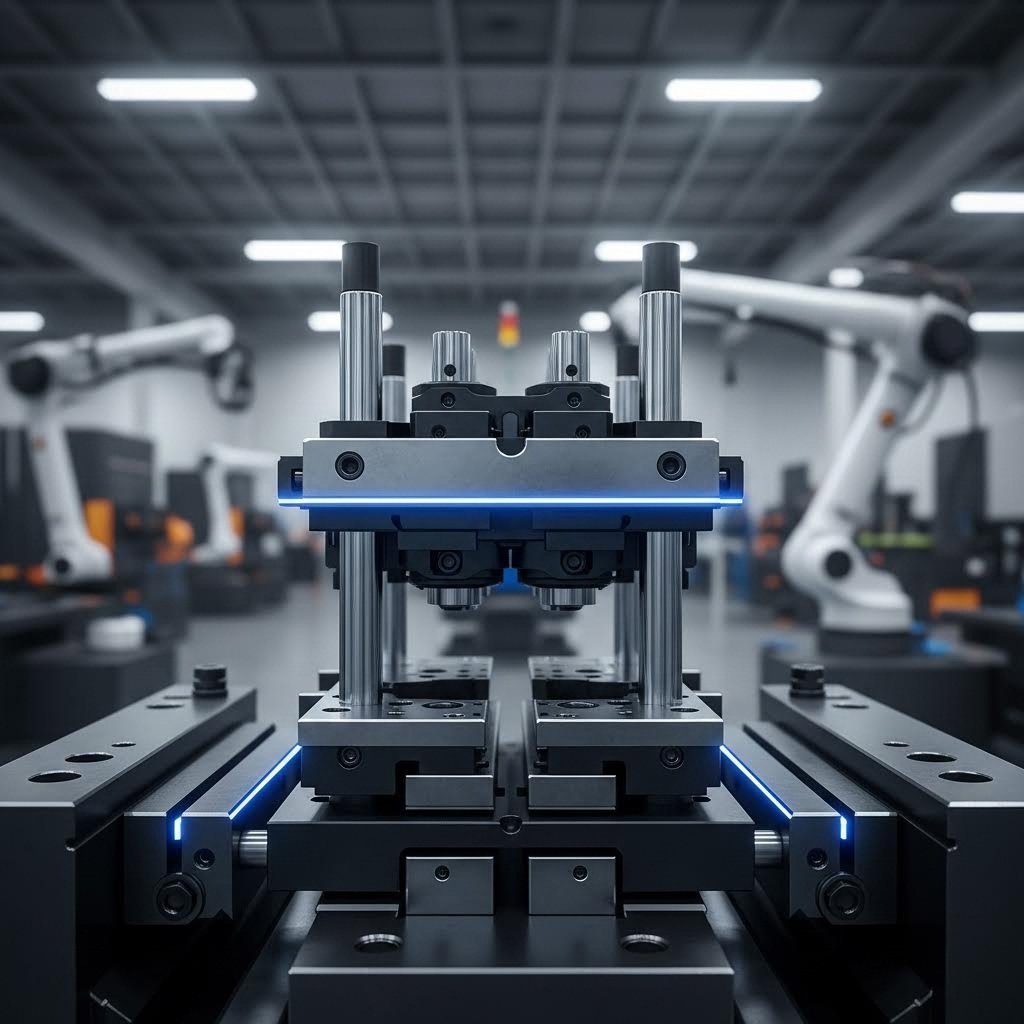
V-ați întrebat vreodată ce face posibilă formarea metalului la viteză ridicată? În inima fiecărei operațiuni de ambutisare se află un set de matrițe pentru ambutisare — ansamblul fundamental care transformă foi plane de metal în componente cu forme precise. Înțelegerea naturii unui set de matrițe și a modului în care acesta funcționează oferă inginerilor, cumpărătorilor și specialiștilor din domeniul producției cunoștințele necesare pentru a lua decizii mai bune privind dotările .
Deci, ce este o matriță în domeniul fabricației? Pe scurt, un set de matrițe este un ansamblu realizat cu precizie, compus dintr-o placă superioară și una inferioară pentru matrițe, menținute în aliniere exactă prin intermediul unor tije ghid și a unor bucși. Atunci când este montat într-o presă, acest ansamblu oferă cadru rigid și repetabil care susține toate operațiunile de tăiere, deformare și modelare. Gândiți-vă la el ca la scheletul uneltei de ambutisare — tot restul se construiește pe această fundație esențială.
Componentele esențiale care asigură funcționarea seturilor de matrițe
Când examinați atent un set de matrițe, veți observa mai multe componente interconectate care lucrează împreună. Fiecare joacă un rol specific în asigurarea formării precise și consistente a metalelor. Mai jos găsiți o descriere detaliată a componentelor principale ale matriței și a funcțiilor acestora:
- Tălpa superioară a matriței (placa superioară): Suprafața de montare pentru poansoane și echipamentele superioare ale matriței. Se atașează la batiul presei și se deplasează vertical în timpul funcționării.
- Tălpa inferioară a matriței (placa inferioară): Denumită și placă de matriță, această componentă fixă se montează pe masa presei și menține în poziție butoanele de matriță, arcurile și uneltele inferioare de deformare.
- Pinoane de ghidare: Pinoane cilindrice rectificate cu precizie, care mențin alinierea exactă între tălpile superioară și inferioară. Acestea sunt fabricate în limite de toleranță de 0,0001" conform standardelor industriale și asigură o poziționare repetabilă pe parcursul a milioane de cicluri.
- Bushings de ghidare: Manguile întărite care primesc tijele ghid, disponibile în variante cu frecare sau cu rulouri. Bushing-urile cu rulouri au devenit standardul industrial datorită ușurinței de separare și a funcționării fluide.
Aceste componente formează structura esențială a matrițelor. Ce sunt matrițele fără o aliniere corespunzătoare? În esență, acestea sunt echipamente care prezintă riscuri legale, produc piese neuniforme și accelerează uzura unor scule costisitoare.
De ce este esențială alinierea precisă în deformarea metalului
Imaginați-vă că apăsați un poansoan prin metal când talpile superioară și inferioară sunt chiar ușor dezaliniate. Vă veți confrunta cu tăiere neregulată, uzură prematură a sculelor și piese care nu trec inspecția de calitate. De aceea, alinierea precisă nu este opțională — este fundamentală pentru operațiunile de ambutisare reușite.
Relația dintre colțarii de ghidare și bucșele creează ceea ce inginerii numesc „mişcare ghidată”. Aceasta asigură faptul că partea superioară a matriței se deplasează pe o traiectorie perfect verticală în raport cu partea inferioară, menținând jocuri constante între piesele active (punch-uri) și butoanele matriței. Seturile moderne de matrițe de ambutisare ating o precizie de aliniere măsurată în zecimi de miime de inch, permițând toleranțe strânse, cerute în aplicațiile din domeniul automotive, aerospace și electronic.
Indiferent dacă evaluați pentru prima dată un set de matrițe sau actualizați echipamentele existente, înțelegerea acestor principii fundamentale vă pune într-o poziție avantajoasă pentru a lua decizii informate privind configurația, materialele și selecția furnizorilor — subiecte pe care le vom explora în detaliu pe parcursul acestui ghid.
Tipuri de configurații ale seturilor de matrițe și momentul potrivit pentru utilizarea fiecăreia
Acum că înțelegeți componentele fundamentale, vă întrebați probabil — cum se asamblează aceste elemente în diferite aranjamente? Răspunsul se află în configurațiile seturilor de matrițe. Alegerea stilului potrivit de matriță influențează direct accesibilitatea în timpul montării, precizia alinierii în timpul funcționării și eficiența generală a producției. Să analizăm cele patru configurații principale și să vă ajutăm să determinați care aranjament de set de matrițe pentru presă se potrivește nevoilor dvs. specifice.
Configurații cu posturi posterioare versus configurații cu patru posturi — explicație
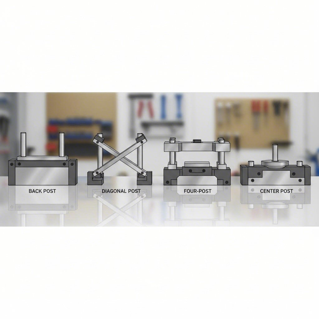
Când examinați seturile de matrițe disponibile pe piață, veți întâlni patru configurații principale, bazate pe poziționarea posturilor de ghidare. Fiecare aranjament oferă avantaje distincte, în funcție de cerințele aplicației dvs.
Configurație cu posturi posterioare: Această configurație populară plasează două colțari de ghidare de-a lungul marginii posterioare a sabotelor matriței. De ce este important acest lucru? Asigură accesibilitate maximă din față și din lateral pentru alimentarea benzii de material, îndepărtarea pieselor finite și efectuarea întreținerii. Specialiștii în utilaje pentru matrițe recomandă frecvent aranjamentele cu colțari posteriori pentru matrițele progresive, unde banda de material este alimentată continuu dintr-o singură parte.
Configurație diagonală cu colțari: Aici, doi colțari sunt amplasați în colțurile opuse — de obicei în pozițiile din fața-stânga și spate-dreapta. Acest aranjament echilibrează accesibilitatea cu o stabilitate îmbunătățită comparativ cu configurațiile cu colțari posteriori. Veți constata că configurațiile diagonale sunt deosebit de utile atunci când operatorii au nevoie de acces din mai multe direcții, fără a compromite calitatea alinierii.
Configurație cu patru colțari: Cu un post de ghidare în fiecare colț, această concepție asigură rigiditate maximă și precizie ridicată în aliniere. Posturile suplimentare distribuie forțele de încărcare uniform pe toată suprafața talerelor matriței, făcând seturile de matrițe cu patru posturi ideale pentru operațiuni intensive de decupare, materiale groase și aplicații care necesită toleranțe foarte strânse. Compromisul? Acces redus pentru alimentare și evacuarea pieselor.
Configurație cu post central: Mai puțin frecventă, dar valoroasă pentru anumite aplicații, configurația cu posturi centrale plasează elementele de ghidare în apropierea centrului zonei matriței. Această configurație este potrivită pentru operațiuni care necesită acces egal din toate părțile sau pentru aranjamente speciale ale sculelor, unde posturile din colțuri ar interfera cu componentele matriței.
Potrivirea tipului de set de matrițe nevoilor dumneavoastră de producție
Alegerea configurației adecvate nu constă în identificarea celei „mai bune” opțiuni, ci în potrivirea capacităților cu cerințele specifice de producție. Luați în considerare următorii factori atunci când analizați un grafic de matrițe sau evaluați furnizorii :
- Direcția de alimentare a materialului: Designurile cu posturi posterioare se remarcă atunci când banda este alimentată din față spre spate; posturile diagonale funcționează mai bine pentru aranjamentele de alimentare înclinată.
- Cerințe privind evacuarea pieselor: Piesele complexe care necesită eliminarea manuală beneficiază de configurații cu partea frontală deschisă.
- Forța nominală și grosimea materialului: Forțele mai mari și materialele mai groase necesită rigiditatea superioară oferită de configurațiile cu patru posturi.
- Cerințe privind toleranțele: Aplicațiile de precizie justifică investiția în configurații cu patru posturi, datorită stabilității superioare a alinierii.
Tabelul de comparație de mai jos oferă o prezentare cuprinzătoare pentru a vă ghida în luarea deciziei:
| Configurare | Accesibilitate | Rigiditate | Precizie la aliniere | Aplicații tipice | Tipuri de prese recomandate |
|---|---|---|---|---|---|
| Posterior | Excelent (3 laturi deschise) | Moderat | Bun | Matrițe progresive, operații de alimentare cu bandă | Presse OBI, stampare înaltă viteză |
| Stâlp diagonal | Foarte bun (două colțuri deschise) | Bun | Bună până la foarte bună | Matrițe de transfer, necesită acces multidirecțional | Presse cu cadru deschis, presse cu cadre drepte |
| Stâlp cu patru colțuri | Limitat (toate colțurile ocupate) | Excelent | Excelent | Decupare grea, deformare precisă, materiale groase | Presse cu cadre drepte, prese hidraulice |
| Stâlp central | Bun (toate părțile parțial deschise) | Moderat la Bun | Bun | Unelte specializate, cerințe de acces simetrice | Diverse tipuri de prese, în funcție de aplicație |
Rețineți că suporturile matrițelor trebuie să corespundă configurației alese — dispunerea stâlpilor determină tiparele de găuri atât în suportul superior, cât și în cel inferior. La comandarea din cataloage sau de la furnizori, verificați dacă specificațiile configurației sunt compatibile cu dimensiunile bazei presei și cu cerințele de strângere.
Înțelegerea acestor configurații vă pregătește pentru următoarea decizie esențială: selectarea materialului potrivit pentru seturile dvs. de matrițe, în funcție de volumul de producție și de cerințele de performanță.
Ghid de selecție a materialelor pentru seturile de matrițe din oțel și aluminiu
Ați selectat configurația dumneavoastră — acum vine o altă decizie care influențează direct durabilitatea sculelor, costurile de producție și eficiența operațională. Din ce material trebuie să fie realizat setul dumneavoastră de matrițe pentru ambutisare? Această alegere afectează totul, de la durata de viață a matriței metalice până la ușurința cu care operatorii o manipulează în timpul montării. Să analizăm diferențele practice dintre matrițele din oțel și alternativele din aluminiu, astfel încât să puteți potrivi proprietățile materialelor cerințelor specifice de producție.
Calități de oțel pentru scule destinate producției de mare volum
Când volumele de producție ajung la sute de mii sau milioane de cicluri, oțelul pentru scule devine alegerea evidentă pentru matrițele de ambutisare metalică . De ce? Oțelul oferă o durabilitate, o rezistență la uzură și o stabilitate dimensională fără egal sub impacturi repetate de înaltă forță.
Majoritatea producătorilor specifică componentele setului de matrițe metalice din următoarele categorii comune de oțel pentru scule:
- Oțel instrumental A2: Un oțel care se întărește la aer, oferind o rezistență excelentă la uzură și o tenacitate bună. Este frecvent utilizat pentru cămășile matrițelor care suportă forțe de impact moderate.
- Oțel de scule D2: Un oțel cu conținut ridicat de carbon și crom, care oferă o rezistență superioară la uzură. Este ideal pentru matrițele de deformare plastică a metalelor în volume mari, acolo unde uzura prin abraziune este principala preocupare.
- Oțel instrumental O1: Un oțel care se întărește în ulei și care este mai ușor de prelucrat decât D2. Este adesea ales atunci când geometriile complexe necesită o prelucrare extensivă înainte de tratamentul termic.
- Oțel pentru scule S7: Un oțel rezistent la șocuri, conceput pentru aplicații cu impact ridicat. Luați în considerare această calitate atunci când operațiunile de ambutisare implică decuparea masivă sau prelucrarea materialelor groase.
Uneltele din oțel pentru matrițe sunt supuse, în mod obișnuit, unui tratament termic pentru a obține durități între 58–62 HRC pe suprafețele active. Acest proces de întărire asigură faptul că materialul rezistă milioanelor de cicluri de presare fără modificări semnificative ale dimensiunilor sau degradarea suprafeței.
Compromisurile? Oțelul adaugă o greutate semnificativă ansamblului de matrițe. Un set de matrițe din oțel cu patru colțuri poate cântări câteva sute de lire sterline, necesitând macarale suspendate sau transpaloare pentru schimbarea matrițelor. Această greutate crește, de asemenea, costurile de transport și impune considerente mai riguroase privind montarea presei.
Când seturile de matrițe din aluminiu sunt rentabile
Pare că oțelul este întotdeauna răspunsul? Nu chiar. Seturile de matrițe din aluminiu și-au creat un segment valoros în operațiunile moderne de ambutisare, în special în anumite scenarii de producție în care proprietățile lor unice oferă avantaje reale.
Luați în considerare aluminiul pentru setul dvs. de matrițe metalice atunci când:
- Prototipare și serii scurte: Când aveți nevoie de mai puțin de 50.000 de piese, costurile mai mici ale materialului și ale prelucrării aluminiului depășesc adesea durata sa de viață redusă.
- Schimbări frecvente ale matrițelor: Aluminiul cântărește aproximativ o treime din greutatea oțelului. Pentru operațiunile care necesită mai multe schimbări de matrițe pe schimb, reducerea greutății se traduce în configurări mai rapide și într-o obosire mai mică a operatorilor.
- Aplicații sensibile la căldură: Conductivitatea termică superioară a aluminiului disipează căldura mai eficient în timpul operațiunilor la viteză ridicată, reducând potențial necesarul de lubrifiant.
- Formare cu tonaj scăzut: Materialele subțiri și forțele modeste de formare nu necesită durabilitatea extremă a oțelului.
Aliajele moderne de aluminiu de calitate aerospațială (6061-T6 și 7075-T6) oferă caracteristici surprinzător de bune de uzură, atunci când sunt corect specificate. Unii producători aplică anodizare dură sau placare cu nichel pe talpile matrițelor din aluminiu, prelungind astfel durata de funcționare, fără a compromite avantajele legate de greutate.
Oțel versus aluminiu: o comparație directă
Tabelul următor rezumă diferențele cheie pentru a vă ajuta să evaluați care material se potrivește cerințelor dumneavoastră de producție:
| Factor | Seturi de matrițe din oțel pentru scule | Seturi de matrițe din aluminiu |
|---|---|---|
| Greutate | Greu (aproximativ 0,283 lb/in³) | Ușor (aproximativ 0,098 lb/in³ — aproximativ 1/3 din greutatea oțelului) |
| Durabilitate | Excelent; suportă milioane de cicluri | Moderat; cel mai potrivit pentru sub 100.000 de cicluri, fără tratamente de suprafață |
| Costuri inițiale | Costuri mai mari pentru material și prelucrare | Costuri mai mici pentru material; prelucrarea mai rapidă reduce cheltuielile cu forța de muncă |
| Conductivitate termică | Mai scăzut; reține căldura în timpul operațiunilor la viteză ridicată | Mai ridicat; disipează căldura aproximativ de 4 ori mai rapid decât oțelul |
| Cazuri ideale de utilizare | Producție în volum mare, decupare intensă, materiale groase, toleranțe strânse | Prototipare, serii scurte, schimbări frecvente ale configurației, deformare a materialelor subțiri |
| Întreținere | Necesită prevenirea coroziunii; rectificare periodică a suprafețelor uzate | Rezistent la coroziune; poate necesita înlocuirea suprafeței în cazul apariției fenomenului de galling |
O considerație practică adesea neglijată: sculele dvs. de decupare nu trebuie să fie realizate în întregime dintr-un singur material. Unii producători specifică tije ghid din oțel și talere de decupare din aluminiu, combinând precizia de aliniere a oțelului tratat termic cu reducerea greutății oferită de plăcile din aluminiu. Această abordare hibridă funcționează în mod deosebit bine pentru aplicații de volum mediu, unde niciunul dintre cele două extreme nu este aplicabil în totalitate.
Indiferent de materialul pe care îl alegeți, asigurați-vă compatibilitatea acestuia cu cerințele presei și cu volumele de producție. Alegerea corectă echilibrează investiția inițială cu costurile operaționale pe termen lung — un calcul care conduce în mod natural la înțelegerea modului de dimensionare și specificare corespunzătoare a setului de decupare pentru echipamentul specific de presă.
Cum să alegeți setul potrivit de decupare pentru cerințele presei dvs.
Ați stabilit configurația și preferințele privind materialele—dar aici este locul în care mulți cumpărători greșesc. Cum vă asigurați că setul de matrițe de ambutisare se potrivește, de fapt, și funcționează în mod optim în presa dvs. specifică? Alegerea unei matrițe de dimensiune incorectă generează probleme de aliniere, limitează capacitatea de producție și poate chiar deteriora echipamente costisitoare. Să parcurgem împreună un cadru practic de luare a deciziilor care corelează specificațiile matriței cu capacitățile mașinii dvs.
Calcularea cerințelor privind dimensiunea setului de matrițe
Înainte de a comanda orice matrițe pentru presă, trebuie să stabiliți volumul dimensional disponibil în echipamentul dvs. de ambutisare. Gândiți-vă la acest lucru ca la măsurarea unei încăperi înainte de a cumpăra mobilier—doar că consecințele unei erori sunt mult mai costisitoare.
Începeți prin colectarea următoarelor măsurători esențiale din specificațiile presei dvs.:
- Dimensiunile bazei: Lungimea și lățimea mesei presei determină suprafața maximă pe care o pot ocupa seturile de matrițe pentru operațiunile de presare. Lăsați întotdeauna margini de siguranță pentru echipamentele de strângere și considerentele de siguranță.
- Înălțimea închiderii: Această măsură reprezintă distanța de la masa presei până la partea inferioară a bielei când aceasta este complet coborâtă. Grosimea totală a tălpii matriței, împreună cu înălțimea sculelor, trebuie să se încadreze în acest interval.
- Lungimea cursei: Distanța de deplasare verticală a bielei influențează spațiul disponibil pentru evacuarea pieselor și alimentarea materialului între cicluri.
- Deschidere de lumină: Distanța maximă dintre masă și bielă atunci când presa este complet deschisă. Această dimensiune este importantă pentru procedurile de încărcare și descărcare a matrițelor.
Când alegeți dimensiunea sabotelor matriței, se aplică un principiu general: setul de matriță trebuie să ofere o suprafață de lucru adecvată pentru echipamentele dvs., lăsând în același timp un margin suficient pentru montare și reglare. Inginerii experimentați în domeniul echipamentelor recomandă, de obicei, ca dimensiunile sabotelor matriței să depășească amprenta reală a echipamentelor dvs. cu un margin suficient pentru a permite fixarea cu cleme, găurile de ghidare și orice modificări viitoare.
Luați în considerare acest scenariu practic: imaginați-vă că piesa dvs. necesită o suprafață de lucru de 12" × 18". Va trebui să alegeți saboți de matriță de dimensiuni mai mari — de exemplu, 16" × 22" — pentru a permite montarea elementelor de fixare, a șuruburilor de extracție și a unei distanțe corespunzătoare față de margine. Alegerea directă a dimensiunii minime posibile pentru matriță generează complicații în timpul asamblării și limitează flexibilitatea dvs. în ceea ce privește reglările ulterioare ale echipamentelor.
Factori de compatibilitate cu presele pe care nu îi puteți ignora
Dimensionarea nu este doar o chestiune de a încăpea prin ușă — matrița mașinii dvs. trebuie să funcționeze armonios cu mecanismele presei pe parcursul a milioane de cicluri. Iată ce trebuie să verificați înainte de a finaliza selecția setului de matriță:
- Capacitate în tone: Tonnajul nominal al presei dvs. trebuie să depășească forțele necesare pentru operațiunea de ambutisare. O capacitate insuficientă creează condiții periculoase de suprasolicitare; o capacitate excesivă risipește energie și accelerează uzura.
- Paralelismul batiului: Precizia alinierii batiului presei dvs. influențează modul în care funcționează setul de matrițe. Matrițele de înaltă precizie necesită echipamente de presă la fel de precise pentru a menține o calitate constantă a pieselor.
- Configurația găurilor de fixare: Verificați dacă configurația găurilor de fixare ale talpii matriței corespunde canalelor în T ale mesei presei sau dispozitivelor de strângere. Configurațiile standard variază între producătorii de prese.
- Diametrul știftului (dacă este cazul): Pentru matrițele care folosesc știfturi superioare pentru fixarea la batiu, asigurați-vă că dimensiunea știftului corespunde exact cu diametrul alezajului batiului presei.
- Înălțimea liniei de alimentare: La ce înălțime intră materialul în bandă în presă? Setul de matrițe trebuie să poziționeze sculele la înălțimea corectă față de echipamentele de alimentare.
Volumul de producție influențează, de asemenea, deciziile privind dimensiunile. Volumele mai mari justifică investiția în seturi de matrițe mai mari și mai rezistente, capabile să suporte acumularea de tensiuni pe durata unor serii lungi. Aplicațiile cu serii scurte pot accepta ansambluri de tip ușor, dar niciodată nu se renunță la precizia alinierii, indiferent de cantitatea produsă.
Potrivirea specificațiilor setului de matrițe cu capacitățile presei nu este opțională — este baza operațiunilor sigure și eficiente de ambutisare. Adoptarea unor soluții rapide în acest domeniu generează probleme care se amplifică pe întreaga durată a ciclului de producție.
O listă practică de verificare pentru alegerea materialului
Înainte de a vă angaja în ceea ce privește orice set de matrițe pentru presă hidraulică sau echipament de ambutisare pentru presă mecanică, parcurgeți aceste verificări de compatibilitate:
- Confirmați că dimensiunile mesei permit amplasarea talpii matriței, inclusiv spațiul necesar pentru strângerea cu cleme
- Verificați dacă înălțimea de închidere permite grosimea totală a ansamblului de matriță, cu un joc de reglare
- Asigurați-vă că lungimea cursei oferă spațiu suficient pentru evacuarea piesei
- Asigurați-vă că forța nominală a presei depășește cerințele calculate de forță pentru ambutisare
- Potriviți prevederile de montare dintre talpile matriței și masa presei
- Verificați lungimea colților de ghidare în raport cu deschiderea disponibilă la nivelul luminii
- Luați în considerare integrarea echipamentului de alimentare și traseele de curgere a materialului
În caz de îndoială, consultați specificațiile producătorului presei și discutați cerințele cu furnizorul setului de matrițe. Furnizorii de încredere dețin experiență în potrivirea produselor lor cu diverse platforme de prese și pot identifica problemele de compatibilitate înainte ca acestea să devină probleme costisitoare.
Odată ce setul de matrițe este corect dimensionat și adaptat presei, următoarea prioritate devine menținerea funcționării continue și fără probleme pe termen lung — ceea ce ne conduce la practicile de întreținere și inspecție care prelungesc durata de viață a matriței și păstrează calitatea producției.
Practici recomandate privind întreținerea și inspecția seturilor de matrițe
Setul dvs. de matrițe de ambutisare este corect dimensionat, configurat corespunzător și funcționează în producție — dar iată realitatea pe care mulți producători o neglijează. Chiar și cea mai precis proiectată asamblare de matrițe se degradează în timp. Tijele de ghidare se uzează, bucșele dezvoltă joc, iar alinierea se deplasează ciclu după ciclu. Fără protocoale sistematice de întreținere, aceste modificări subtile apar în cele din urmă ca defecțiuni de calitate, opriri neplanificate ale producției și reparații de urgență costisitoare.
Conform specialiștilor în producție de la The Phoenix Group întreținerea necorespunzătoare a matrițelor provoacă defecțiuni de calitate în timpul producției, determinând creșterea costurilor de sortare și mărirea probabilității de livrare a pieselor defecte. Costurile ascunse depășesc pierderile prin rebut — liniile de asamblare trebuie să modifice dispozitivele și sistemul de fixare pentru a compensa variațiile pieselor cauzate de uzura sculelor. Să stabilim procedurile de inspecție și practicile preventive care mențin matrițele dvs. de precizie la nivelul maxim de performanță.
Puncte de control pentru inspecție în vederea prelungirii duratei de viață a setului de matrițe
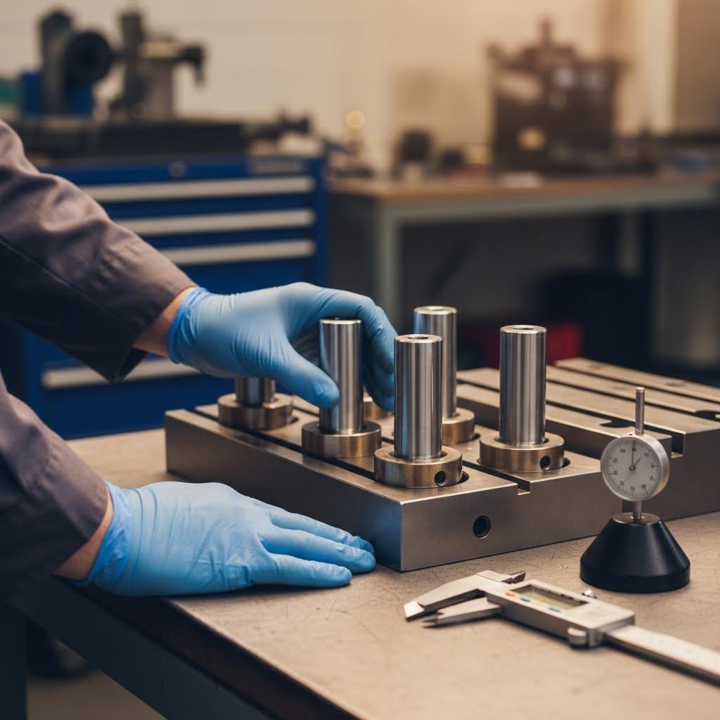
Gândiți-vă la inspecția setului de matrițe ca la o formă de medicină preventivă pentru operațiunea dumneavoastră de ambutisare. Detectarea problemelor în stadiu incipient — înainte ca acestea să provoace defecțiuni — costă mult mai puțin decât intervențiile reactive în timpul urgențelor de producție. O rutină structurată de inspecție acoperă trei intervale de timp critice:
Înainte de fiecare serie de producție:
- Inspectați vizual tijele ghid pentru zgârieturi, gripare sau deteriorări ale suprafeței, care indică probleme de aliniere
- Verificați ajustarea bucșelor prin simțirea jocului excesiv în timpul ciclării manuale a ansamblului de matrițe
- Asigurați-vă că talpile matriței se așează perfect plane pe patul presei, fără oscilații sau goluri
- Confirmați prezența tuturor bolțurilor de fixare și strângerea lor corectă
- Inspectați suprafețele active pentru resturi de material, rugină sau depozite de lubrifiant rezidual
În timpul monitorizării producției:
- Ascultați sunete neobișnuite — clicuri, scrâșnete sau zgomote intermittente de contact semnalează apariția unor probleme
- Monitorizați dimensiunile pieselor la intervale regulate pentru a detecta deviații progresive
- Monitorizați cerințele crescute de forță care sugerează blocarea sau nealiniația
- Verificați temperatura de funcționare a tijelor ghid și a bucșelor pentru depunerea anormală de căldură
Inspecție după rulare:
- Curățați integral toate suprafețele înainte de depozitare sau înainte ca următorul operator de reglare a matrițelor să înceapă configurarea
- Documentați orice probleme descoperite în timpul rulării în sistemul dumneavoastră de comenzi de lucru
- Măsurați diametrul tijelor ghid în punctele de uzură și comparați-l cu specificațiile de referință
- Inspectați alezajele bucșelor pentru prezența unor semne de gripare, zgârieturi sau deformări (ne-circularitate)
Când reașezați ansamblurile de matrițe în depozitare, aplicați un agent anticoroziv pe suprafețele expuse de oțel. Această simplă măsură previne coroziunea, care accelerează uzura în ciclul următor de producție.
Recunoașterea modelelor de uzură înainte ca acestea să provoace defecțiuni
Constructorii experimentați de matrițe dobândesc o viziune specializată asupra modelelor de uzură care prezic probleme viitoare. Iată ce trebuie să căutați pe echipamentele dumneavoastră de matrițe în timpul inspecțiilor rutiniere:
Uzură a colțarilor de ghidare: Verificați zonele lucioase sau brunite care indică contact metal-pe-metal. Colțarii de ghidare în stare bună prezintă o finisare uniformă a suprafeței pe întreaga lor lungime. Modele locale de uzură — în special urmele oblice — sugerează o dezaliniere între talpile superioară și inferioară ale matriței, care necesită corecție imediată.
Deteriorarea bucșelor: Bucșele cu rulouri sferice trebuie să funcționeze ușor, cu rezistență minimă. Dacă simțiți asperitate, blocare sau auziți un zgomot de frecare în timpul operației manuale, rulourile sunt defecte. Bucșele de frecare își măresc progresiv diametrul interior în timp — monitorizați aceste dimensiuni și înlocuiți bucșele atunci când jocul depășește specificațiile fabricantului.
Deriva de aliniere: Probabil cea mai insidioasă problemă, deriva aliniamentului are loc atât de treptat încât operatorii se adaptează fără să-și dea seama că calitatea se degradează. Observați următoarele semne de avertizare:
- Piese care necesită din ce în ce mai multă finisare sau operații secundare
- Înălțimea bavurilor care crește pe marginile pieselor tăiate
- Uzura poansoanelor concentrată pe o singură parte, în loc să fie distribuită uniform
- Urmări de desfundare care apar în locații noi pe bandă
Frecvența întreținerii matrițelor determină direct consistența calității producției. Producătorii care efectuează inspecții sistematice înregistrează mai puține reparații de urgență, rate mai scăzute de deșeuri și o producție mai previzibilă — corelația este incontestabilă.
Protocoale de întreținere preventivă eficiente
Trecerea de la o întreținere reactivă la una preventivă transformă atelierul de matrițe dintr-o operațiune de stins incendii într-un activ strategic. Mai jos găsiți un cadru practic bazat pe ciclurile de producție, nu pe programe calendaristice arbitrare:
- La fiecare rulare de producție: Curățați, inspectați și documentați starea înainte de depozitare
- La fiecare 50.000–100.000 de cicluri: Măsurați diametrele tijelor ghid și jocurile din bucșele de ghidare în comparație cu specificațiile de referință
- La fiecare 250.000 de cicluri: Efectuați o verificare detaliată a alinierii folosind echipamente de măsurare de precizie
- Anual sau conform recomandărilor producătorului: Demontare completă, inspecție și înlocuirea componentelor uzate, după caz
Documentarea activităților de întreținere creează date istorice valoroase. Atunci când apar probleme de calitate, puteți urmări în mod retroactiv dacă starea matriței corelează cu modelele de defecte. Această abordare bazată pe date ajută, de asemenea, la previziunea momentului în care componentele vor necesita înlocuire, permițând programarea proactivă, nu reacționarea de ultimă oră.
O matriță bine întreținută nu doar că are o durată de viață mai lungă — ci produce, de asemenea, piese mai consistente pe întreaga sa perioadă de funcționare. Totuși, chiar și cu practici excelente de întreținere, uneori pot apărea probleme. Înțelegerea modului de diagnosticare și corectare a celor mai frecvente defecțiuni ale seturilor de matrițe previne transformarea unor probleme minore în perturbări majore ale producției.
Diagnosticarea și rezolvarea problemelor comune ale seturilor de matrițe
Chiar și cu o întreținere atentă, problemele apar în cele din urmă în orice set de matrițe de ambutisare. Când piesele eșuează brusc la inspecție sau presa dumneavoastră începe să emită sunete neobișnuite, cum identificați rapid cauza fundamentală? Diferența dintre un ajustament minor și o întrerupere prelungită depinde adesea de viteza și acuratețea diagnosticului. Să analizăm împreună cele mai frecvente defecțiuni ale seturilor de matrițe, simptomele lor caracteristice și acțiunile corective care vă permit să reveniți rapid în producție.
Diagnosticarea problemelor de aliniere în producție
Problemele de aliniere se află printre cele mai frustrante probleme, deoarece se dezvoltă treptat. Într-o zi, totul funcționează perfect; săptămâni mai târziu, vă luptați cu defecțiuni de calitate care par să apară aleatoriu. Înțelegerea modului în care se manifestă dezalinierea vă ajută să detectați problemele înainte ca acestea să provoace reparații costisitoare.
Monitorizați aceste semne de avertizare în timpul producției:
- Modele neuniforme de bavură: Când bururile apar mai pronunțate pe o singură parte a pieselor decupate, poansonul și matrița dvs. nu se întâlnesc concentric. Acest lucru indică o deplasare laterală între talpele superioară și inferioară.
- Uzură progresivă a poansonului: Conform specialiștilor în diagnosticarea problemelor de la DGMF Mold Clamps, uzura neuniformă pe suprafețele poansonului — unde unele zone prezintă zgârieturi mai mari și se uzează mai rapid — semnalează probleme de aliniere între sediile de montare ale platourilor rotative superior și inferior.
- Derivă dimensională: Piesele care măsurau corect săptămâna trecută acum depășesc toleranțele, în special la caracteristicile formate prin interacțiunea dintre poanson și matriță.
- Modele neobișnuite de zgomot: Zgomotele de clic, de frecare sau de contact intermitent în timpul ciclării preced adesea problemele vizibile de calitate.
Când bănuiți probleme de aliniere, începeți diagnosticul de la sursă. Utilizați un mandrin de aliniere pentru a verifica relația dintre turnul presei și baza de montare. De multe ori, problema nu este deloc matrița și sculele dvs., ci chiar preasa, care s-a deviat din specificațiile inițiale.
Operațiunile de deformare cu matrițe sunt deosebit de sensibile la aliniere, deoarece curgerea materialului depinde de contactul constant dintre piesa activă (punch) și suprafața matriței. Chiar și abateri minime generează o distribuție neuniformă a eforturilor, provocând ondulări pe o parte și ruperi pe cealaltă.
Măsuri corective pentru defecțiunile frecvente ale seturilor de matrițe
După ce ați identificat problema, care este soluția? Tabelul următor organizează problemele frecvente ale seturilor de matrițe într-un cadru de diagnostic pe care specialiștii din domeniul fabricației îl pot aplica imediat:
| Problema | Simptome | Cauzele principale | Măsuri Corective |
|---|---|---|---|
| Alinierea greșită | Bavuri neuniforme, uzură unilaterală a piesei active (punch), variații dimensionale | Bushings ghid deteriorate, tije ghid deteriorate, dezaliniere a turnului presei, reglare incorectă a matriței | Verificați și ajustați alinierea turnului folosind un mandrin; înlocuiți bushings-urile uzurate; verificați dacă talpile matriței se așează perfect plane pe masa presei; luați în considerare prelucrarea matrițelor cu ghidaj complet pentru aplicații critice |
| Pierderea preciziei | Repere care ies din toleranțe, poziții nesigure ale găurilor, abateri de formă | Uzură a colților de ghidare, dilatare termică în timpul funcționării prelungite, elemente de fixare slabe, revenirea elastică a materialului | Măsurați diametrele colților de ghidare în comparație cu valorile de referință; permiteți stabilizarea termică înainte de efectuarea măsurătorilor critice; verificați dacă toate buloanele de fixare sunt strânse la cuplul specificat; implementați compensarea revenirii elastice în proiectarea matriței |
| Uzură prematură | Răni pe colții de ghidare, degradare rapidă a bucșelor, deteriorare a suprafețelor în zonele de lucru | Lubrifiere insuficientă, contaminare a lubrifiantului, jocuri neadecvate, viteză excesivă a presei | Revizuiți și îmbunătățiți procedura de lubrifiere; filtrați sau înlocuiți lubrifiantul contaminat; verificați dacă jocul dintre poanson și matriță corespunde grosimii materialului (de obicei 8–12% din grosime); reduceți viteza ciclului matriței, dacă este necesar |
| Găurilor | Transfer de metal între suprafețe, blocare a componentelor, funcționare neregulată | Materiale incompatibile în contact, lubrifiere insuficientă, presiune excesivă în punctele de contact | Aplicați învelișuri anti-gripare (TiN, TiAlN); treceți la lubrifianți EP (de presiune extremă); reduceți forța de fixare a piesei dacă este cazul; luați în considerare tratamente de suprafață, cum ar fi nitrurarea, pentru aplicațiile matrițelor de decupare |
| Blocarea tijelor ghid | Rezistență în timpul ciclării, mișcare neregulată, acumulare de căldură | Acumulare de deșeuri, deteriorare a alezajului bucșelor, tije îndoițe sau zgâriate, neconformitate a dilatării termice | Curățați în mod atent toate suprafețele ghid; inspectați bucșele pentru eventuale deformări (ne-rotunditate); înlocuiți imediat tijele deteriorate; verificați dacă jocul este adecvat pentru dilatarea termică în regimul de funcționare la viteză ridicată |
Observați câte probleme se datorează acelorași cauze fundamentale? Defecțiunile de ungere, problemele de joc și deraparea alinierii reprezintă cea mai mare parte a defecțiunilor matrițelor. Abordați aceste aspecte în mod sistematic și veți preveni majoritatea defecțiunilor înainte ca acestea să apară.
Pentru problemele persistente care nu cedează corecțiilor standard, luați în considerare următoarele abordări avansate de diagnostic:
- Verificarea cu indicator cu cadran: Montați indicatorii pe partea superioară a șablonului și deplasați-i pe suprafața inferioară a matriței pentru a cuantifica nealiniația în miimi de inch.
- Verificări ale contactului cu colorant albastru: Aplicați colorant de mecanic pe suprafețele de contact, efectuați o singură ciclare a matriței și examinați modelele de contact pentru a identifica angrenarea neuniformă.
- Imagistica termică: În timpul rulărilor prelungite, camerele termice evidențiază zonele fierbinți care indică blocarea, frecarea excesivă sau lubrifierea insuficientă.
Când acțiunile corective necesită introducerea de distanțiere sau ajustări ale jocurilor, lucrați în mod incremental. Experiența din industrie sugerează limitarea ajustărilor la maximum 0,15 mm pe iterație, pentru a evita corecții excesive. Documentați fiecare modificare — ceea ce părea astăzi o soluție rapidă devine date diagnostice valoroase atunci când probleme similare reapar luni mai târziu.
Uneori problema reală nu este setul de matrițe în sine, ci modul în care acesta se integrează în sistemul dvs. mai larg de producție. Înțelegerea poziției pe care o ocupă seturile de matrițe de stampare în cadrul întregului ecosistem de deformare a metalelor vă ajută să identificați problemele care au originea în aval sau în amonte față de scule.
Poziția seturilor de matrițe de stampare în operațiunile de deformare a metalelor
Înțelegerea modului de diagnosticare a problemelor legate de scule este esențială — dar ați luat în considerare modul în care setul dvs. de matrițe de stampare se conectează la imaginea mai amplă a procesului de fabricație? Aceste ansambluri de precizie nu funcționează izolat. Ele constituie baza pentru diverse tipuri de matrițe și metode de producție în aproape toate industriile care transformă tabla metalică în componente finite. Să explorăm acest ecosistem mai amplu și să vedem unde se încadrează deciziile dvs. privind sculele.
Seturile de matrițe în operațiunile de stampare progresivă și de transfer
Gândiți-vă la un ansamblu de matrițe de ambutisare ca la o scenă pe care se pot desfășura diferite stiluri de performanță. Aceeași bază aliniată cu precizie susține abordări de fabricație profund diferite, în funcție de cerințele dumneavoastră de producție.
Matricile progresive: Într-o operație de ambutisare progresivă , o bandă continuă de metal este alimentată automat prin mai multe stații integrate într-un singur ansamblu de matrițe. Fiecare stație efectuează o operație specifică — decupare, perforare, îndoire sau deformare — în succesiune, până când piesa finită iese din proces. Conform specialiștilor din domeniu, soluțiile cu matrițe progresive se remarcă în ambutisarea metalică de înalt volum datorită automatizării complete, unele operații atingând producții zilnice de peste 11.000 de piese după o optimizare corespunzătoare.
Matrițe de transfer: Asemănător cu tehnologia progresivă, dar mai flexibil, matrițele de transfer preiau piesele individuale de prelucrat și le deplasează între stații, în loc să se bazeze pe materialul sub formă de bandă continuă. Setul de matrițe oferă cadru rigid pentru fiecare stație, în timp ce mecanismele automate de transfer gestionează deplasarea materialului. Această abordare reduce deșeurile de material, deoarece nu există o bandă portantă care să conecteze piesele.
Matrițe combinate: Uneori denumite și matrițe combinate, aceste matrițe avansate de ambutisare execută mai multe operații — cum ar fi decuparea, perforarea, reliefarea și îndoirea — într-o singură cursă a presei, la o singură stație. Setul de matrițe trebuie să asigure o aliniere excepțională, deoarece toate operațiile de tăiere și deformare au loc simultan, cerând relații precise între componentele superioare și cele inferioare ale sculelor.
Industria matrițelor continuă să evolueze aceste configurații. Producătorii moderni utilizează adesea abordări hibride, combinând flexibilitatea operațiunilor într-o singură etapă cu viteza matrițelor progresive prin sisteme automate de transfer. Semifabricatele se deplasează fără întreruperi între stații, maximizând productivitatea, în timp ce mențin toleranțele strânse impuse de stamparea de precizie.
Aplicații industriale de la automotive la aerospace
Unde se aplică, de fapt, toate aceste configurații ale matrițelor pentru stampare metalică? Răspunsul acoperă practic fiecare sector care se bazează pe componente metalice formate cu precizie. Conform cercetărilor din domeniu, piața stampării metalice este previzionată să crească de la 205 miliarde de dolari în 2021 la peste 283 miliarde de dolari până în 2030 — o creștere determinată de extinderea aplicațiilor în mai multe industrii.
Iată unde matrițele pentru stampare și seturile lor de susținere adaugă valoare:
- Automotive: De la panourile structurale ale caroseriei până la carcasele complexe ale senzorilor, fabricarea autovehiculelor depinde în mare măsură de matrițele de deformare. Trecerea către vehiculele electrice creează noi oportunități, în special pentru aplicații legate de învelișurile bateriilor și componentele superioare ale caroseriei, care găzduiesc senzori și camere.
- Electronice de consum: Sectorul electronicii de consum generează o cerere semnificativă de ambutisare metalică, cu aplicații în cadrele telefoanelor mobile, componente ale căștilor, carcasele difuzoarelor și elementele controlerelor pentru jocuri video, toate acestea necesitând o precizie excepțională.
- Producerea de electrocasnice: Tamburii mașinilor de spălat, panourile frigiderelelor și componentele sistemelor de climatizare și ventilare (HVAC) provin toate din operațiuni de ambutisare. Cerințele de producție în volum mare justifică investiția în fabricarea robustă a uneltelor și matrițelor pentru aceste aplicații.
- Aeronautice: Unde toleranțele se măsoară în miimi de milimetru și specificațiile materialelor sunt extrem de riguroase, fabricarea matrițelor pentru industria aerospațială reprezintă vârful preciziei. Componentele trebuie să îndeplinească standarde stricte de calitate, menținând în același timp integritatea structurală în condiții extreme.
- Telecomunicații: Carcasele, radiatoarele de căldură și suporturile structurale pentru echipamentele de rețea se bazează pe decupare de precizie. Expansiunea rapidă a infrastructurii 5G continuă să stimuleze cererea din acest domeniu.
- Dispozitive medicale: Instrumentele chirurgicale, componentele pentru implante și carcasele echipamentelor de diagnostic necesită operații de deformare fără contaminare și cu un control excepțional al dimensiunilor.
Fabricarea matrițelor pentru aceste aplicații diverse implică cerințe comune: aliniere precisă, selecția adecvată a materialelor și configurații adaptate volumelor de producție. Indiferent dacă produceți suporturi auto sau elemente de fixare pentru industria aerospațială, principiile fundamentale ale selecției seturilor de matrițe rămân aceleași — doar parametrii specifici se modifică.
Cu această înțelegere a rolului pe care îl au seturile de matrițe de decupare în cadrul mai larg al lanțului de producție, sunteți mai bine pregătiți să evaluați potențialii furnizori capabili să vă susțină cerințele specifice privind industria și obiectivele de producție.
Alegerea unui furnizor de calitate pentru seturi de matrițe în funcție de nevoile dvs. de producție
Ați stăpânit fundamentalele selecției seturilor de matrițe pentru amprentare—configurații, materiale, dimensiuni și întreținere. Dar aici teoria se confruntă cu realitatea: găsirea unui furnizor care să poată livra efectiv ceea ce aveți nevoie, exact când aveți nevoie, la nivelul de calitate cerut de producția dumneavoastră. Partenerul de fabricare a matrițelor pe care îl alegeți influențează totul, de la costurile inițiale ale echipamentelor până la consistența producției pe termen lung. Ce distinge, deci, furnizorii excepționali de cei care doar primesc comenzi?
Indiferent dacă achiziționați o matriță personalizată pentru validarea unui prototip sau stabiliți o relație de colaborare pentru echipamente de producție în volum mare, criteriile de evaluare rămân remarcabil de constante. Să analizăm factorii cei mai importanți în alegerea partenerului dumneavoastră specializat în matrițe de precizie și în amprentare.
Certificări de calitate relevante pentru standardele OEM
Când furnizați componente pentru industria auto, aerospace sau alte industrii solicitante, materialele dvs. pentru matrițe trebuie să provină din surse certificate. Certificările nu sunt doar decorațiuni pentru pereți — ele reprezintă sisteme verificate de management al calității, control al proceselor și îmbunătățire continuă.
Certificare IATF 16949: Dacă serviți lanțul de aprovizionare auto, această certificare este obligatorie. Conform Autorității de certificare NSF , IATF 16949 oferă un Sistem Standardizat de Management al Calității care se concentrează pe stimularea îmbunătățirii continue, cu accent pe prevenirea defectelor și reducerea variațiilor și a deșeurilor. Majoritatea producătorilor auto OEM importanți impun această certificare partenerilor lor din lanțul de aprovizionare.
De ce este important acest lucru pentru matrițele destinate aplicațiilor de fabricație? Furnizorii certificați mențin proceduri documentate pentru fiecare aspect al producției matrițelor — de la proiectarea inițială până la inspecția finală. Atunci când apar probleme, sistemele de calitate trazabile permit identificarea rapidă a cauzei fundamentale și aplicarea unor acțiuni corective. Organizațiile certificate conform IATF 16949 demonstrează o satisfacție sporită a clienților, o eficiență crescută și o gestionare mai bună a riscurilor în cadrul întregii lor activități.
În afară de IATF 16949, căutați furnizori care dețin certificarea ISO 9001 ca standard de bază privind calitatea, precum și certificări specifice industriei, relevante pentru aplicația dumneavoastră. Aplicațiile din domeniul aerospațial pot necesita conformitatea cu AS9100, în timp ce matrițele destinate dispozitivelor medicale impun respectarea standardului ISO 13485.
Suport ingineresc și capacități de prototipare
Iată o realitate pe care mulți cumpărători o ignoră: oferta de preț cea mai mică pentru construcția matrițelor devine adesea alegerea cea mai costisitoare. De ce? Pentru că furnizorii care nu dispun de o experiență tehnică solidă livrează matrițe care necesită modificări extensive, produc piese neuniforme sau se defectează prematur. Valoarea reală constă în partenerii specializați în construcția matrițelor și a uneltelor de stampare care previn problemele înainte de începerea producției.
Simulare CAE pentru prevenirea defectelor: Ingineria modernă a matrițelor folosește ingineria asistată de calculator (CAE) pentru a vizualiza procesele de deformare înainte de tăierea oțelului. Așa cum explică specialiștii în simulare a deformării metalelor , analiza CAE permite vizualizarea evoluției sarcinilor, a deformărilor și a variațiilor de temperatură în timpul procesului de deformare, precum și predicția defectelor potențiale, cum ar fi fisurile care ar putea apărea în timpul producției. Prin optimizarea proiectării matrițelor pe baza rezultatelor simulărilor, defectele pot fi prevenite din timp, asigurându-se astfel o producție mai fluentă și reducerea semnificativă a costurilor componentelor.
Această capacitate de simulare este extrem de importantă pentru aplicațiile de matrițe de precizie și de ambutisare. În loc să descopere probleme de deformare în timpul încercărilor—când modificările sunt costisitoare și consumatoare de timp—furnizorii echipați cu CAE identifică problemele în faza de proiectare, când modificările au un cost practic nul.
Termenele pentru prototiparea rapidă: Planurile de producție rareori permit cicluri prelungite de dezvoltare a sculelor. Atunci când lansarea produsului dumneavoastră depinde de matrițele de ambutisare validate, termenele de livrare ale furnizorilor devin constrângeri critice. Căutați parteneri care oferă capacități de prototipare rapidă capabili să livreze scule funcționale pentru testarea de validare în termene foarte scurte.
Shaoyi își exemplifică această combinație de competențe, oferind certificarea IATF 16949 alături de simulări avansate CAE pentru rezultate fără defecțiuni. Echipa lor de ingineri realizează prototipare rapidă în doar 5 zile, sprijinind termenele accelerate de dezvoltare impuse de producția modernă auto. Cu o rată de aprobare la prima verificare de 93% pentru sculele de stampilare, demonstrează rezultatele de calitate pe care le face posibilă o asistență inginerescă adecvată. Puteți explora capacități complete de proiectare și fabricare a matrițelor pentru a vedea cum se combină aceste elemente.
Criterii cheie de evaluare a furnizorilor
La compararea potențialilor furnizori de scule și matrițe pentru stampilare, parcurgeți aceste puncte critice de verificare:
- Certificări de Calitate: IATF 16949 pentru aplicații auto; verificați starea actuală a certificării și istoricul auditurilor
- Capacități ingineresci: Simulări CAE, analiză DFM (Design for Manufacturability) și ingineri experimentați în domeniul sculelor, care înțeleg industria dumneavoastră
- Viteză de prototipare: Pot livra scule funcționale în cadrul termenului dumneavoastră de dezvoltare? Solicitați angajamente specifice privind termenele de livrare
- Ratele de aprobare la prima încercare: Ce procentaj din echipamentele lor respectă specificațiile la prima prezentare? Liderii din industrie obțin rate de aprobare de peste 90%
- Capacitatea Volumului de Producție: Pot să treacă de la cantități prototip la producție în volum mare fără degradarea calității?
- Experțise în Materiale: Înțeleg aliajele și grosimile specifice pe care le formați? Cunoașterea materialelor previne erorile costisitoare de proiectare
- Comunicare și Asistență: Cât de reactivi sunt în timpul dezvoltării? Vă vor oferi sprijin tehnic continuu și după livrare?
- Considerente geografice: Proximitatea influențează termenele de livrare, costurile de transport și fezabilitatea colaborării in loc pentru încercări
Dincolo de acești factori tangibili, evaluați potrivirea culturală. Cele mai bune relații cu furnizorii funcționează ca parteneriate, în care ambele părți investesc în succesul reciproc. Furnizorii care pun întrebări detaliate despre aplicația dumneavoastră, care contestă ipotezele în mod constructiv și care sugerează proactiv îmbunătățiri obișnuiesc să ofere rezultate superioare față de cei care se limitează doar la ofertare conform desenelor.
Considerațiile legate de cronograma producției merită o atenție deosebită. Dezvoltarea matrițelor personalizate implică mai multe etape — proiectare, revizuire inginerescă, fabricare, tratament termic, asamblare și probă. Fiecare etapă oferă posibilități de întârziere dacă furnizorii nu dispun de capacitate, expertiză sau management eficient al proiectelor. Solicitați cronograme detaliate ale proiectului, cu angajamente clare privind etapele cheie, și verificați dacă furnizorii au capacitatea adecvată pentru proiectul dumneavoastră, având în vedere și sarcina lor de lucru existentă.
Acum că ați stabilit criterii clare pentru evaluarea furnizorilor de seturi de matrițe, sunteți pregătiți să luați decizii informate privind achiziționarea. Dar cum puteți sintetiza tot ceea ce am abordat până acum într-un plan de acțiune practic? Să consolidăm considerentele cheie într-un cadru de luare a deciziilor pe care îl puteți aplica imediat.
Luarea deciziei privind setul de matrițe pentru ambutisare cu încredere
Ați parcurs un teren semnificativ — de la înțelegerea componentelor de bază până la evaluarea capacităților furnizorilor. Acum vine momentul critic: transformarea cunoștințelor în acțiune. Indiferent dacă specificați pentru prima dată un set de matrițe de ambutisare sau perfecționați strategia de achiziții pentru producția în volum mare, o abordare structurată previne erori costisitoare și accelerează drumul către piese de calitate.
Gândiți-vă la această secțiune finală ca la busola decizională. Considerentele pe care le-am explorat pe parcursul acestui ghid se concretizează în pași de acțiune specifici pe care îi puteți implementa imediat — indiferent dacă lucrați cu un catalog standard de seturi de matrițe Danly sau dezvoltați echipamente complet personalizate pentru aplicații specializate.
Verificare privind selecția setului de matrițe
Înainte de a vă angaja într-o configurație anume de presă și matriță, parcurgeți sistematic aceste decizii fundamentale. Ignorarea sau accelerarea oricărui pas generează probleme care se acumulează pe întreaga durată de viață a producției dumneavoastră:
- Definiți cerințele de producție: Stabiliți volumele anuale, complexitatea pieselor, specificațiile materialelor și cerințele de toleranță. Acești parametri determină fiecare decizie ulterioară privind configurația, materialul și selecția furnizorilor.
- Potriviți configurația aplicației: Selectați suportul posterior pentru operațiunile progresive care necesită accesibilitate maximă, suportul diagonal pentru acces echilibrat și stabilitate sau suportul cu patru colțuri atunci când rigiditatea și precizia sunt mai importante decât accesibilitatea.
- Alegeți materialele potrivite: Oțel pentru durabilitate ridicată la volume mari, depășind 100.000 de cicluri; aluminiu atunci când reducerea greutății, prototiparea rapidă sau schimbările frecvente justifică compromisurile.
- Verificați compatibilitatea presei: Confirmați dimensiunile mesei, înălțimea de închidere, lungimea cursei și capacitatea de încărcare în tone înainte de finalizarea oricărui set de specificații pentru matrițe. Necoresponderțele aici generează riscuri de siguranță și probleme de calitate.
- Stabiliți protocoalele de întreținere: Planificați frecvențele de inspecție, programul de ungere și bazele de măsurare a uzurii înainte de începerea producției — nu după apariția problemelor.
- Calificați potențialii furnizori: Verificați certificatele (IATF 16949 pentru industria auto), competențele ingineresci, termenele pentru prototipare și ratele de aprobare la prima încercare, pe baza unor dovezi documentate.
- Solicitați termenele detaliate ale proiectului: Obțineți angajamente privind etapele cheie ale fazelor de proiectare, fabricație și încercare. Programările neclare indică, de obicei, limitări legate de capacitate sau competențe.
Această abordare sistematică se aplică atât în cazul achiziționării matrițelor standard pentru prese de forță, cât și în cazul investițiilor în echipamente de tip progresiv complexe. Principiile de bază rămân aceleași — doar parametrii specifici se modifică în funcție de aplicația dumneavoastră.
Trecerea la următorul pas în proiectul dumneavoastră de echipamente
Gata să treceți de la planificare la execuție? Următorii pași depind de stadiul în care vă aflați în ciclul de dezvoltare:
Dacă vă aflați în fazele inițiale de proiectare: Implicați potențialii furnizori acum—înainte ca proiectele să fie finalizate. Partenerii pentru construcția matrițelor de ambutisare, care dispun de solide capacități ingineresti, pot identifica problemele de fabricabilitate în timp ce modificările rămân ieftine. Această abordare colaborativă reduce, de obicei, durata totală de dezvoltare și previne redesignurile costisitoare în faza de încercare.
Dacă achiziționați pentru proiecte existente: Concentrați evaluarea asupra furnizorilor care demonstrează sisteme de calitate dovedite și capacități de răspuns rapid. Pentru aplicații auto, Shaoyi oferă un exemplu excelent al caracteristicilor căutate: certificare IATF 16949, simulări avansate CAE pentru prevenirea defectelor și capacități de prototipare rapidă care permit livrarea unor matrițe funcționale în doar 5 zile. Rata lor de aprobare la prima încercare de 93% demonstrează rezultatele de calitate pe care le face posibilă o susținere inginerescă adecvată. Explorați soluțiile complete de matrițe de ambutisare pentru a vedea cum se aliniază aceste capacități cu cerințele dumneavoastră.
Dacă rezolvați probleme legate de matrițele existente: Examinați cadrele de diagnostic prezentate anterior, concentrându-vă pe verificarea alinierii și analiza modelelor de uzură. Uneori, calea cea mai cost-eficientă de urmat implică recondiționarea seturilor existente de matrițe, în locul înlocuirii lor în întregime.
Indiferent de stadiul în care vă aflați, rețineți această adevăr fundamental: calitatea setului dumneavoastră de matrițe pentru ambutisare determină direct calitatea fiecărei piese pe care o produce. Investiția într-o selecție adecvată, furnizori certificați și întreținere sistematică aduce beneficii pe parcursul a milioane de cicluri de producție. Deciziile privind sculele pe care le luați astăzi vor modela rezultatele activității dumneavoastră de fabricație pentru ani de zile.
Întrebări frecvente despre seturile de matrițe pentru ambutisare
1. Ce este un set de matrițe pentru ambutisare și ce funcție îndeplinește?
Un set de matrițe de ambutisare este un ansamblu realizat cu precizie, compus dintr-o placă superioară și una inferioară de matriță, menținute în aliniere exactă prin tije ghid și bucși. Acesta servește ca structură de bază pentru operațiunile de ambutisare a metalelor, susținând toate procesele de tăiere, deformare și modelare. Placa superioară de matriță se fixează de batiul presei, iar cea inferioară se montează pe masa presei, tijele ghid asigurând o precizie de aliniere de 0,0001 inch pe parcursul a milioane de cicluri de producție.
2. Care sunt tipurile diferite de configurații ale seturilor de matrițe?
Există patru configurații principale ale seturilor de matrițe: cu colțuri posterioare (două colțuri de-a lungul marginii din spate pentru accesibilitate maximă), cu colțuri diagonale (colțuri în colțurile opuse pentru acces echilibrat și stabilitate), cu patru colțuri (câte un colț în fiecare colț pentru rigiditate și precizie maxime) și cu colț central (ghiduri în apropierea centrului pentru aplicații specializate). Designul cu colțuri posterioare este excelent pentru matrițele progresive cu alimentare prin bandă, în timp ce configurațiile cu patru colțuri sunt ideale pentru decupare masivă și pentru cerințe stricte de toleranță.
3. Ar trebui să aleg oțel sau aluminiu pentru setul meu de matrițe?
Alegeți oțelul pentru scule în cazul producției de volum mare, care depășește 100.000 de cicluri, unde durabilitatea și stabilitatea dimensională sunt esențiale. Seturile de matrițe din aluminiu sunt avantajoase din punct de vedere economic pentru prototipare, serii scurte sub 50.000 de piese, schimbări frecvente ale matrițelor (aluminiul cântărește aproximativ o treime din greutatea oțelului) și aplicații sensibile la temperatură. Unele fabrici folosesc abordări hibride, cu colțuri ghid de oțel și talpe de matriță din aluminiu, pentru a combina precizia cu reducerea greutății.
4. Cum aleg dimensiunea corectă a setului de matrițe pentru presa mea?
Începeți prin măsurarea dimensiunilor mesei presei, înălțimii de închidere, lungimii cursei și a deschiderii libere. Tălpile matrițelor trebuie să depășească amprenta sculelor cu un joc suficient pentru elementele de fixare, cleme și reglaje. Verificați dacă capacitatea de forță (în tone) depășește cerințele de forță pentru ambutisare, confirmați că configurația găurilor de montare corespunde canalelor în formă de T ale presei și asigurați-vă că lungimea tijelor ghid este compatibilă cu deschiderea liberă disponibilă. Lăsați întotdeauna jocuri de siguranță pentru fixare și considerente de siguranță.
5. Ce certificate ar trebui să cautați la un furnizor de seturi de matrițe?
Pentru aplicațiile destinate industriei auto, certificarea IATF 16949 este esențială, deoarece demonstrează sisteme verificate de management al calității, cu accent pe prevenirea defectelor și îmbunătățirea continuă. ISO 9001 reprezintă un standard de bază privind calitatea, în timp ce aplicațiile destinate industriei aeronautice pot necesita conformitatea cu AS9100. Furnizorii precum Shaoyi oferă certificarea IATF 16949 combinată cu capacități avansate de simulare CAE și prototipare rapidă în doar 5 zile, obținând rate de aprobare la prima încercare pentru scule de 93%.