 Serii mici, standarde ridicate. Serviciul nostru de prototipare rapidă face validarea mai rapidă și mai ușoară —

Procesul de fabricație prin amprentare decodificat: de la foaia brută la piesa finită
Ce înseamnă de fapt ambutisarea în fabricația modernă
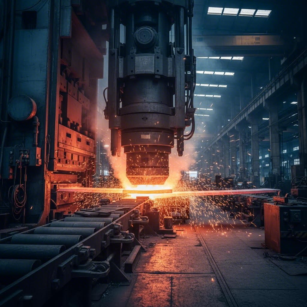
V-ați întrebat vreodată cum sunt realizate, cu o precizie atât de remarcabilă, panourile caroseriei mașinii dumneavoastră sau conectoarele minuscule din interiorul smartphone-ului dumneavoastră? Răspunsul se află în una dintre cele mai puternice tehnici de fabricație: amprentarea metalică. Acest proces de fabricație transformă tabla metalică plană în componente cu forme precise, prin aplicarea unor forțe controlate și utilizarea unor scule specializate — producând totul, de la simpli suporturi până la piese auto complexe, cu viteze uimitoare.
De la foaia plană la piesa finită
Ce este, de fapt, amprentarea metalică? În esență, acest proces folosește o presă de amprentare pentru a conduce o matriță durificată în tabla metalică, tăind, îndoiind sau modelând materialul în forme specifice. Imaginați-vă un tăietor de biscuiți — dar conceput să reziste la mii de lire forță și capabil să producă piese identice de mii de ori pe oră.
Semnificația amprentării în domeniul fabricației diferă semnificativ de amprentarea decorativă sau cea realizată în artizanat. Aici vorbim despre producția la scară industrială, unde rolele de metal plan intră într-o extremitate a procesului, iar componente finite ies din cealaltă extremitate. Conform Documentației Wikipedia privind prelucrarea metalelor , piesele obținute prin amprentare au revoluționat fabricația încă din anii 1880, când au înlocuit forjarea cu matrițe și prelucrarea prin așchiere pentru componente ale bicicletelor, reducând în mod spectaculos costurile de producție, fără a compromite calitatea acceptabilă.
Fizica deformării metalelor
Ce face procesul de amprentare metalică atât de eficient? Totul se bazează pe deformarea controlată. Atunci când presa aplică o forță prin matriță, tabla metalică suferă o deformare plastică — își schimbă forma în mod permanent, fără a se rupe. Matrița acționează simultan ca o formă și ca un instrument de tăiere, în funcție de operația specifică efectuată.
Amprentarea modernă se bazează pe calculuri precise ale proprietăților materialelor , cerințele de forță și geometria sculelor. Lubrifianții protejează atât sculele, cât și metalul ambutisat împotriva deteriorării suprafeței, permițând în același timp materialului să curgă ușor în forme complexe. Această coordonare atentă a forței, sculelor și științei materialelor este ceea ce diferențiază operațiunile de ambutisare reușite de cele eșuate.
De ce domina ambutisarea producția în masă
Care este cel mai mare avantaj al unei operațiuni de ambutisare? Viteza și consistența. În timp ce prelucrarea mecanică ar putea produce o singură piesă complexă în câteva minute, ambutisarea poate crea zeci de piese pe minut — fiecare aproape identică cu precedenta. Această eficiență explică de ce producătorii auto, companiile de electronice și cei care fabrică electrocasnice se bazează în mare măsură pe această tehnologie.
După cum subliniază analiza de specialitate a Die-Matic, ambutisarea se remarcă în producția de volum mare, unde sunt necesare mii sau milioane de piese identice, cu variații minime. Acest proces asigură toleranțe strânse și durabilitate constantă — cerințe esențiale pentru industrii precum cea auto sau cea aerospațială, unde fiabilitatea pieselor influențează direct siguranța.
La ce se folosește astăzi metalul ambutisat? Îl veți găsi peste tot: panouri de caroserie și suporturi în vehicule, componente pentru plăci de circuit în electronice, elemente structurale în aeronave și nenumărate piese pentru electrocasnice. Această versatilitate, combinată cu eficiența costurilor la scară largă, asigură faptul că ambutisarea rămâne colțuna spinală a fabricației moderne.
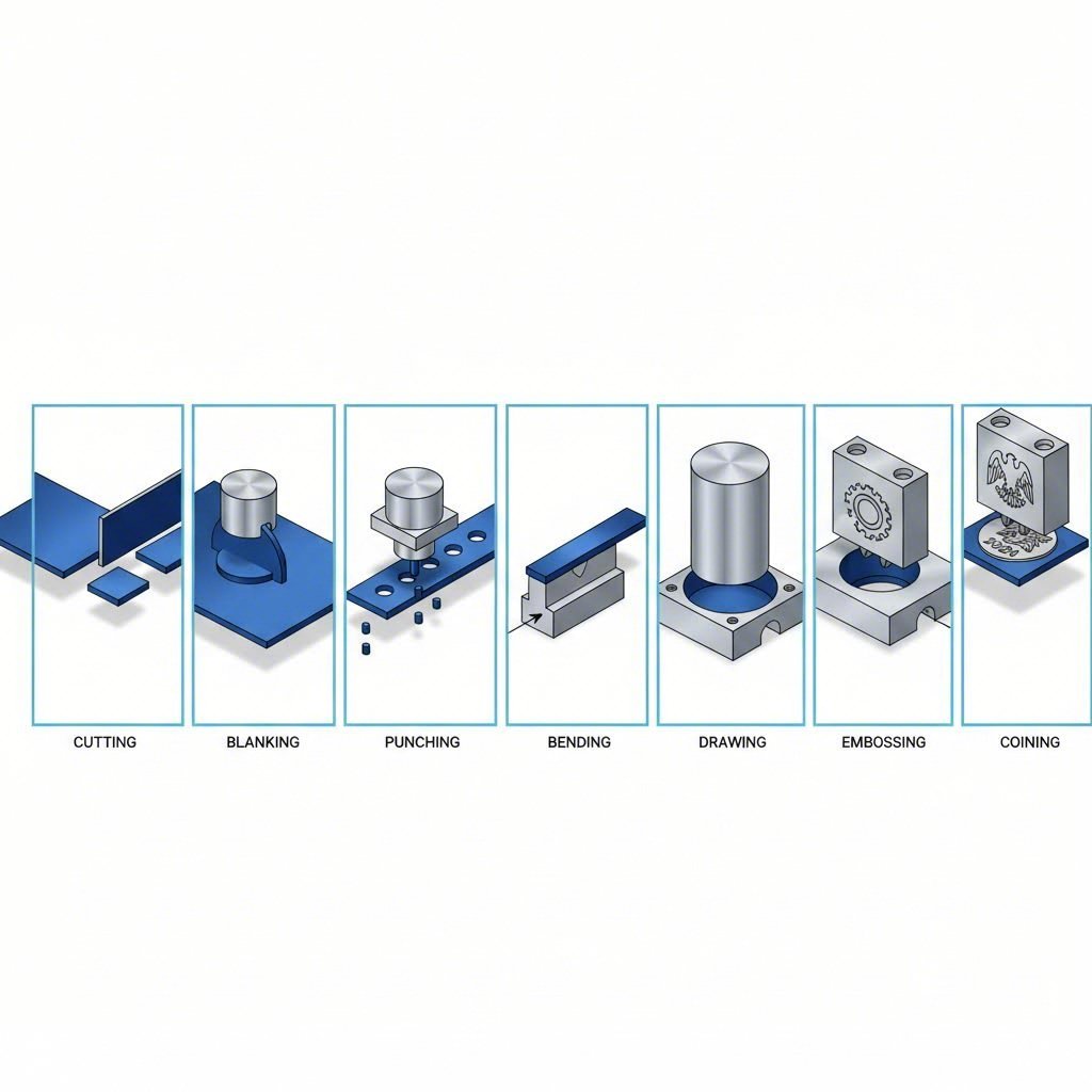
Șapte operațiuni fundamentale de ambutisare pe care fiecare inginer ar trebui să le înțeleagă
Acum că înțelegeți ce înseamnă ambutisarea în contextul fabricației, să explorăm operațiunile specifice care fac din acest proces unul atât de versatil. Gândiți-vă la aceste operațiuni ca la unelte individuale din atelierul unui meșter — fiecare este concepută pentru un anumit scop, dar este adesea combinată cu altele pentru a crea piese finite complexe. Indiferent dacă proiectați componente sau evaluați opțiunile de fabricație , înțelegerea acestor șapte operațiuni de bază vă va ajuta să luați decizii mai bine fundamentate.
Explicarea operațiunilor de tăiere
Operațiunile de tăiere constituie baza celei mai mari părți a proceselor de ambutisare. Ele separă materialul, creează deschideri și stabilesc forma de bază a componentei dumneavoastră. Două operațiuni principale de tăiere domină industria:
- Decupaj – Această operație taie forme plane din foi de metal pentru a obține piesa de bază. În timpul operațiilor de decupare (blanking) a metalului, o piesă de tip matriță (punch) pătrunde prin material, iar piesa decupată devine produsul dumneavoastră, în timp ce foaia rămasă devine deșeu. Gândiți-vă la această operație ca la folosirea unui tăietor de biscuiți, unde păstrați biscuitul. Conform Master Products , decuparea (blanking) este optimizată pentru producerea eficientă a unor cantități mari de componente cu forme similare.
- Perforarea (Piercing) – Deși este mecanic asemănătoare cu decuparea (blanking), perforarea creează găuri sau deschideri în piesa de prelucrat. În acest caz, materialul extras prin perforare devine deșeu, iar foaia cu găurile reprezintă produsul dumneavoastră. Această operație de calibrare cu matriță este esențială pentru crearea găurilor de poziționare, a punctelor de conectare și a deschiderilor de ventilare în piesele finite.
Ce diferențiază aceste operații? Pe scurt: piesa pe care o păstrați. La decupare (blanking) se păstrează forma decupată; la perforare se păstrează materialul înconjurător.
Tehnici de deformare și modelare
Odată ce ați stabilit forma de bază prin tăiere, operațiunile de deformare transformă semifabricatele plane în componente tridimensionale. Aceste tehnici manipulează metalul fără a îndepărta material:
- Îndoire – O presă de îndoit aplică o forță extremă pentru a îndoi metalul la unghiuri precise în jurul unei axe specifice. Această operațiune de ambutisare și presare creează componente în formă de V, în formă de U sau cu unghiuri personalizate. Veți găsi piese îndoite peste tot—de la carcase electrice până la suporturi auto.
- Desen – Această tehnică precisă de ambutisare formează piese în formă de cupă sau de cutie, forțând tabla metalică să coboare pe o matriță. Metalul se întinde și curge în jurul geometriei matriței, creând forme complexe în secțiune transversală. Ambutisarea adâncă extinde acest proces pentru piese care necesită o adâncime semnificativă, cum ar fi cutiile pentru băuturi sau rezervoarele de combustibil auto.
- Ribit – Aveți nevoie de designuri ridicate sau în relief pe piesele dvs.? Matrizarea imprimă un model decorativ, litere, logo-uri sau texturi funcționale pe o singură față a semifabricatului. Conform informațiilor furnizate de HLC Metal Parts, acest proces îmbunătățește aspectul produsului, păstrând în același timp integritatea sa structurală.
- Flanșare – Această operație îndoaie marginile în jurul găurilor perforate sau de-a lungul perimetrelor semifabricatului, la unghiuri de 90 de grade. Îndoirea cu flanșă creează margini netede, în locul celor ascuțite, consolidează rezistența structurală și pregătește suprafețele pentru operațiunile de asamblare. Componentele cu flanșă sunt frecvent întâlnite în containere, țevi și panouri ale caroseriei autovehiculelor.
Operații de Precizie pentru Toleranțe Critice
Când aplicația dvs. necesită o precizie excepțională, aceste operații specializate oferă rezultate pe care tehnicile standard nu le pot obține:
- Cunătare – Cel mai precis proces de ambutisare disponibil: ambutisarea prin batere (coining) a oțelului și a altor metale implică ambutisarea simultană a ambelor fețe ale semifabricatului sub o presiune extrem de ridicată. Acest proces comprimă materialul în fiecare detaliu al cavitatea matriței, obținând toleranțe la fel de strânse ca ±0,001 inch. Denumirea provine din fabricarea monedelor — acele detalii clare de pe monedele de 25 de cenți și pe medalioanele comemorative rezultă din operațiunile de ambutisare prin batere.
Fiecare operațiune din procesul de ambutisare își are un rol distinct, dar puterea lor reală apare atunci când sunt combinate. O singură matriță progresivă poate efectua, în stații succesive, operațiuni de decupare (blanking), perforare (punching), îndoire (bending) și flanșare (flanging) ale unui component — transformând astfel banda plană în piese finite în câteva secunde. Înțelegerea momentului potrivit pentru aplicarea fiecărei tehnici vă ajută să proiectați piese realizabile din punct de vedere industrial și să alegeți abordarea de producție adecvată pentru cerințele specifice ale dumneavoastră.
| Operațiune | Funcția principală | Aplicații tipice | Avantaj Cheie |
|---|---|---|---|
| Decupaj | Decuparea formelor plane din foaie | Componente de bază, inele de siguranță, suporturi | Producția în volum mare de forme |
| Lovire | Crearea găurilor și deschiderilor | Găuri de montare, ventilare, conexiuni | Poziționare precisă a găurilor |
| Îndoire | Formarea unghiurilor și a curbelor | Carcase, cadre, suporturi | Creează geometrie 3D din materiale plane |
| Desen | Formarea formelor de cupă/cutie | Recipiente, carcase, capace | Adâncime complexă fără cusături |
| Ribit | Crearea elementelor de suprafață | Logouri, panouri decorative, texturi antiderapante | Îmbunătățire vizuală și funcțională |
| Flanșare | Borduri îndoite la 90° | Rezervoare, conducte, panouri de caroserie | Rezistență îmbunătățită și margini netede |
| Cunătare | Formare precisă la presiune înaltă | Monede, bijuterii, piese cu toleranțe strânse | Precizie excepțională dimensională |
Cu aceste șapte operații în vocabularul dumneavoastră de fabricație, sunteți pregătit să explorați modul în care se combină în fluxuri complete de producție — de la proiectarea inițială până la livrarea piesei finite.
Fluxul complet de lucru al ambutisării metalice: de la proiectare până la livrare
Înțelegerea operațiilor individuale de ambutisare este esențială — dar cum se combină aceste tehnici în producția reală? Procesul de ambutisare a foilor metalice urmează o secvență bine orchestrată, în care fiecare etapă se bazează pe cea precedentă. Dacă omiteți un parametru critic în orice fază, veți întâmpina probleme de calitate, întârzieri în producție sau deșeururi costisitoare. Să parcurgem împreună procesul complet de fabricație prin ambutisare de la conceptul inițial până la componenta finalizată.
Faza de inginerie pre-producție
Înainte ca orice metal să atingă o matriță, trebuie efectuată o cantitate semnificativă de lucrări de inginerie. Această fază determină dacă operațiunea dumneavoastră de stampare în producție va avea succes sau va întâmpina dificultăți.
Pasul 1: Selectarea și pregătirea materialului
Alegerea materialului afectează tot ceea ce urmează în aval. Inginerii evaluează proprietățile mecanice, cum ar fi rezistența la tractiune, ductilitatea și rata de îndurare prin deformare, precum și considerente practice, cum ar fi costul și disponibilitatea. Conform National Material Company, se iau în considerare proprietățile mecanice, cum ar fi rezistența și ductilitatea, precum și factori precum rezistența la coroziune, conductivitatea și costul.
Odată selectate, rolele sau foile brute sunt supuse unor procese de pregătire, printre care:
- Tăierea și divizarea la lățimi adecvate
- Nivelarea pentru a asigura planitatea
- Curățarea suprafeței pentru eliminarea uleiurilor și a contaminanților
- Conditionarea marginilor pentru a preveni problemele de alimentare
Erori frecvente aici? Selectarea materialelor care arată bine pe hârtie, dar se comportă slab în timpul formării, sau sărirea nivelării corespunzătoare — ceea ce duce la o geometrie nesigură a pieselor de-a lungul întregii serii de producție.
Pasul 2: Proiectarea și ingineria matriței
Matrița este, în esență, ADN-ul procesului dumneavoastră de fabricație prin ambutisare. Așa cum se menționează în Ghidul complet al Jeelix privind proiectarea matrițelor , acest pas oferă cea mai mare influență asupra întregului proces — fiecare oră de gândire concentrată investită aici poate economisi zeci de ore de revizii și zeci de mii de euro în costuri ulterioare.
Ingineria matriței implică:
- Elaborarea schemelor de bandă pentru optimizarea utilizării materialului
- Calculul forțelor de tăiere, formare și evacuare
- Determinarea centrului de presiune pentru a preveni uzura neuniformă a matriței
- Selectarea materialelor adecvate pentru matriță, în funcție de volumul de producție și de materialul piesei
- Rularea simulărilor CAE pentru identificarea potențialelor probleme de deformare înainte de încercările fizice
O matriță bine proiectată anticipează problemele înainte ca acestea să apară. Unde va afecta revenirea elastică dimensiunile finale? În care zone există riscul de ondulare sau fisurare? Proiectanții experimentați de matrițe abordează aceste întrebări în faza de inginerie — nu după începerea producției.
Pasul 3: Configurarea și calibrarea presei
Potrivirea matriței la presa adecvată este esențială pentru procesul de deformare prin ambutisare a metalelor. Inginerii calculează cerințele totale de forță (în tone) prin însumarea tuturor forțelor din toate stațiile, apoi selectează o presă cu capacitate suficientă — de obicei cu 20–30 % peste cerințele calculate, pentru marja de siguranță.
Configurarea implică:
- Montarea și alinierea matriței în interiorul presei
- Stabilirea înălțimii corecte de închidere (distanța dintre batiu și traversa la partea inferioară a cursei)
- Programarea lungimii cursei, a vitezei și a timpilor de staționare
- Calibrarea presiunilor hidraulice pentru sistemele de perne și plăci de susținere
- Verificarea dispozitivelor de blocare de siguranță și a senzorilor
Ciclul de ambutisare în acțiune
După finalizarea proiectării și pregătirea echipamentelor, începe producția prin ambutisare metalică. Acesta este momentul în care materialul plan se transformă în componente finite.
Pasul 4: Alimentare și poziționare
Sistemele automate de alimentare livrează materialul în matriță cu o precizie remarcabilă. Materialul din bandă continuă este derulat prin dispozitive de întindere și introdus în alimentatoare cu role acționate servo, care avansează materialul exact pe distanța necesară — adesea în limite de ±0,001 inch — înainte de fiecare cursă.
Alimentarea corectă necesită:
- Lungimea corectă de alimentare, potrivită cu progresia configurației benzii
- Pini de ghidare adecvați, care asigură poziționarea precisă a materialului în interiorul matriței
- Reglaje pentru buclă care previn variațiile de tensiune ale materialului
- Sensoare de alimentare defectuoasă care opresc presei în cazul apariției unor erori de poziționare
La viteze ridicate — uneori depășind 1.000 de curse pe minut — chiar și neregularitățile minime de alimentare se amplifică și generează probleme majore de calitate. Sistemele moderne de control al procesului de ambutisare în producția industrială monitorizează fiecare ciclu.
Pasul 5: Cursa de amprentare
Aici are loc „magia”. Conform RCO Engineering, un ciclu tipic de amprentare presupune coborârea presei către matriță, închiderea matrițelor și modelarea metalului prin forță și presiune ridicate, urmată de eliberarea și retragerea presei.
În această secvență care durează o fracțiune de secundă:
- Batiul coboară, aducând matrița superioară spre matrița inferioară
- Pinoii de ghidare se angajează pentru a asigura o poziționare precisă a materialului
- Operațiile de tăiere, formare sau tragere au loc conform proiectării
- Materialul curge și se deformează în funcție de geometria matriței
- Batiul se retrage, permițând avansarea materialului
Inginerii folosesc lubrifianți în mod strategic în această fază pentru a reduce frecarea, a preveni griparea și a controla curgerea materialului. Sistemele de răcire disipează căldura generată în timpul operațiunilor cu viteză ridicată sau presiune ridicată.
Pasul 6: Ejectarea și manipularea piesei
Piesele finite trebuie să iasă în mod fiabil din matriță—în fiecare ciclu în parte. Plăcile de evacuare împiedică lipirea pieselor de poansoane, iar ejectoarele acționate hidraulic sau cu arc împing piesele finalizate în afara cavității matriței. Jeturile de aer și degetele mecanice pot ajuta la evacuarea și orientarea pieselor.
De asemenea, se impune gestionarea deșeurilor. Sistemele de evacuare a tăieturilor elimină materialul perforat din cavitățile matriței, iar tăietorii de bandă reduc deșeurile provenite din banda portantă, asigurând o eliminare eficientă. O singură tăietură blocată poate provoca deteriorarea catastrofală a matriței în milisecunde.
Verificarea calității după stampare
Pasul 7: Inspecția calității
Procesul de fabricație prin stampare metalică nu se încheie atunci când piesele părăsesc matrița. Măsurile de control al calității asigură faptul că fiecare componentă îndeplinește specificațiile înainte de a ajunge la clienți.
Metodele de inspecție includ:
- Evaluarea vizuală pentru defecte de suprafață, bavuri și probleme estetice
- Măsurarea dimensională folosind calibre, ublere sau mașini de măsurat cu coordonate
- Testarea funcțională pentru verificarea cerințelor de potrivire și de performanță
- Controlul statistic al procesului pentru identificarea tendințelor înainte ca acestea să devină probleme
Multe operațiuni de deformare prin ambutisare din producție includ, de asemenea, procese secundare, cum ar fi îndepărtarea bavurilor, tratamentul termic, placarea sau vopsirea, înainte de asamblarea finală și expediere.
| Treaptă | Scop | Echipament esențial | Parametri critici | Puncte comune de eroare |
|---|---|---|---|---|
| 1. Selectarea și pregătirea materialelor | Asigurați formabilitatea și calitatea corespunzătoare | Linii de tăiere, nivelatoare, curățătoare | Toleranță de grosime, finisaj de suprafață, planitate | Calitate necorespunzătoare a materialului, nivelare insuficientă |
| 2. Proiectarea și ingineria matrițelor | Realizați scule care să producă piese precise | Software CAD/CAM, simulare CAE, prelucrare CNC | Jocuri, dispunerea benzii, calculul forțelor | Compensare insuficientă a revenirii elastice, curgere slabă a materialului |
| 3. Configurarea și calibrarea presei | Configurarea echipamentului pentru o funcționare optimă | Presă de ambutisare, carucioare pentru matrițe, unelte de aliniere | Înălțimea de închidere, capacitatea de presare (în tone), viteza cursei | Dezaliniere, setare incorectă a capacității de presare (în tone) |
| 4. Alimentare și poziționare | Alimentarea precisă a materialului în stațiile matriței | Suporturi pentru role, întinzătoare, alimentatoare servo | Lungimea de alimentare, angajarea ghidului, tensiunea buclei | Alimentare defectuoasă, deteriorare a ghidului, îndoirea materialului |
| 5. Cursa de ambutisare | Modelarea materialului în forma dorită | Batiul presei, matrițele, sistemele de ungere | Distribuția forței, timpul de staționare, ungerea | Fisurare, ondulare, deformare nesigură |
| 6. Ejectarea și manipularea pieselor | Eliminarea pieselor și a deșeurilor în mod fiabil | Plăci de desprindere, ejectoare, transportoare | Momentul ejectării, îndepărtarea deșeurilor, orientarea pieselor | Piese blocate, tragerea borșului, avarierea matrițelor |
| 7. Inspectie de calitate | Verificați dacă piesele corespund specificațiilor | Mașini de măsurat cu coordonate (CMM), comparatoare optice, calibre de tip „da/nu” | Toleranțe dimensionale, calitatea suprafeței, limitele controlului statistic al proceselor (SPC) | Defecte omise, eșantionare insuficientă |
Observați cum se leagă fiecare pas de cel următor? Calitatea pregătirii materialelor influențează uzura matrițelor și consistența pieselor. Proiectarea matriței determină ce trebuie să ofere presa dumneavoastră. Precizia alimentării afectează fiecare operație de deformare. Această natură interconectată explică de ce o producție de calitate în stampare necesită atenție pe întreaga flux de lucru — nu doar la operațiile individuale.
Acum, după ce ați înțeles întregul flux de lucru, sunteți pregătiți să explorați diferitele metode de matrițe care organizează acești pași în sisteme eficiente de producție — de la matrițele progresive, care efectuează mai multe operații în succesiune, până la sistemele de transfer concepute pentru componente mai mari și mai complexe.
Compararea metodelor de matrițe progresive, de transfer și compuse
Ați văzut cum funcționează operațiunile individuale de amprentare și cum acestea se desfășoară într-un ciclu complet de producție. Dar aici lucrurile devin interesante: cum organizează producătorii aceste operațiuni în sisteme de producție eficiente? Răspunsul constă în alegerea metodei potrivite de matriță — iar această decizie poate determina succesul sau eșecul aspectelor economice ale proiectului dumneavoastră.
Gândiți-vă în felul următor: nu ați folosi un ciocan cu greutate pentru a fixa un cadru de pictură, nu-i așa? În mod similar, alegerea dintre amprentarea cu matriță progresivă, cu matriță de transfer și cu matriță compusă depinde în totalitate de ceea ce fabricați, de cantitatea necesară și de complexitatea pieselor amprentate. Să analizăm fiecare abordare, astfel încât să puteți lua decizii informate în ceea ce privește cerințele de proiectare pentru amprentare.
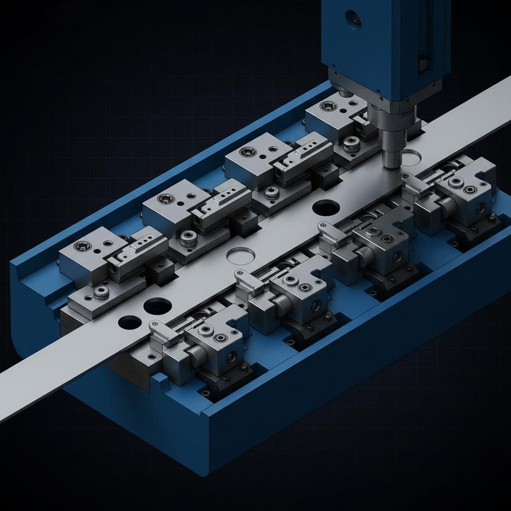
Matriță progresivă pentru eficiență maximă
Imaginați-vă o linie de asamblare comprimată într-un singur instrument. Acesta este principiul matrițelor progresive și al ambutisării în acțiune. O bandă continuă de metal este alimentată prin mai multe stații din cadrul unei singure matrițe, fiecare stație efectuând o operațiune diferită — decupare, perforare, îndoire, deformare — într-o succesiune precisă. Partea rămâne atașată de banda purtătoare pe tot parcursul procesului, separându-se doar la stația finală.
Conform comparației proceselor realizate de Die-Matic, ambutisarea cu matrițe progresive deplasează o bandă de metal prin mai multe stații care efectuează operațiuni diferite, cum ar fi tăierea, îndoirea, perforarea sau perforarea cu ștanță — făcând-o ideală pentru producția în viteză ridicată a pieselor complexe, în volume medii până la mari.
De ce este important acest lucru pentru producția dumneavoastră? Viteza. O singură cursă a presei avansează banda și efectuează operațiuni simultan, la fiecare stație. În timp ce o secțiune este decupată, alta este perforată, iar o a treia este formată — toate în aceeași fracțiune de secundă. Această prelucrare paralelă asigură un debit remarcabil pentru piese obținute prin ambutisare de precizie.
Ambutisarea cu matrițe progresive este avantajoasă atunci când:
- Este necesară o producție de volum mare (mii până la milioane de piese)
- Piesele sunt de dimensiune mică sau medie
- Proiectul dumneavoastră necesită mai multe operațiuni, dar nu și ambutisări profunde
- Consistența și viteza sunt mai importante decât preocupările legate de investiția inițială în scule
Compromisul? Costurile inițiale ale sculelor sunt mai mari decât cele ale soluțiilor mai simple. Conform informațiilor furnizate de Keats Manufacturing, ambutisarea cu matrițe progresive necesită matrițe costisitoare din oțel, dar economisește timp și bani prin efectuarea simultană a mai multor operațiuni, reducerea deșeurilor și posibilitatea unor serii lungi de producție cu costuri reduse ale forței de muncă.
Ambutisarea prin transfer pentru componente mari
Ce se întâmplă atunci când piesele dvs. sunt prea mari pentru matrițele progresive sau când este necesară tragerea profundă? Intervine matrițarea cu matriță de transfer. Spre deosebire de matrițarea progresivă, unde piesele rămân conectate la bandă, matrițarea cu matriță de transfer separă semifabricatul la un stadiu timpuriu — fie începând cu o bucată decupată în prealabil, fie detașând-o la prima stație.
Aici apare partea ingenioasă: degete mecanice sau sisteme automate de transfer mișcă fizic fiecare piesă între stații. Această manipulare „liberă” a pieselor permite operații care ar fi imposibile cu o bandă conectată — tragere mai profundă, orientări mai complexe și acces la zone blocate de materialul purtător în configurațiile progresive.
Conform comparației detaliate realizate de Worthy Hardware, matrițarea cu matriță de transfer oferă o flexibilitate mai mare în ceea ce privește manipularea și orientarea pieselor, fiind potrivită pentru designuri și forme intricate. Aceasta poate integra diverse operații, cum ar fi perforarea, îndoirea, tragerea și decuparea, într-un singur ciclu de producție.
Matrițarea cu matriță de transfer este ideală atunci când:
- Piesele au dimensiuni medii până la mari
- Sunt necesare operațiuni de tragere profundă
- Geometriile complexe necesită mai multe orientări în timpul formării
- Proiectul dumneavoastră include elemente precum fileturi, nervuri sau caneluri
Flexibilitatea este însoțită de anumite considerente. Timpul de configurare poate fi mai lung, costurile operaționale cresc datorită mecanismelor de manipulare mai complexe, iar pentru întreținere veți avea nevoie de tehnicieni calificați. Totuși, pentru componente din tablă ambutisată, cum ar fi panourile de caroserie auto, consolele structurale și carcasele electrocasnicelor, ambutisarea prin transfer reprezintă adesea singura soluție practică.
Matriță compusă: Simplitatea unei singure curse
Uneori cea mai elegantă soluție este cea mai simplă. Ambutisarea cu matriță compusă efectuează mai multe operațiuni de tăiere într-o singură cursă — de obicei combinând decuparea și perforarea pentru a produce piese plane complete, fără stații progresive sau mecanisme de transfer.
Imaginați-vă o piuliță: trebuie să tăiați diametrul exterior (decupare) și gaura centrală (perforare) simultan. O matriță compusă realizează ambele operații într-un singur ciclu de presare. Această abordare asigură o planitate excepțională, deoarece piesa nu este supusă mai multor manevre sau solicitări de alimentare.
Conform Keats Manufacturing, decuparea cu matriță compusă necesită o dotare mai puțin costisitoare decât cea cu matriță progresivă, oferă o producție eficientă și rapidă a pieselor simple și mici și produce, într-o singură cursă, piese mai plane, cu o repetabilitate ridicată.
Decuparea cu matriță compusă este cea mai potrivită pentru:
- Piese plane care necesită doar operații de tăiere (fără deformare)
- Volume medii până la mari de producție
- Componente la care planitatea este esențială
- Geometrii simple, cum ar fi piulițele, garniturile și semifabricatele de roți
Limitarea? Matrițele compuse execută doar operații de tăiere. Aveți nevoie de îndoire, tragere sau deformare? Atunci veți avea nevoie de metode progresive sau de transfer — sau de operații secundare care implică costuri și manipulări suplimentare.
Tehnici specializate pentru cerințe particulare
În afara celor trei metode principale, tehnicile specializate de amprentare rezolvă provocări specifice de fabricație pe care abordările standard nu le pot rezolva eficient.
Amprentare prin tragere adâncă
Când proiectul dumneavoastră de amprentare a foilor metalice necesită piese în formă de pahar, cilindrice sau de tip cutie, cu o adâncime semnificativă, amprentarea profundă devine esențială. Acest proces trage semifabricatele plane în matrițe, întinzând și deformând metalul în forme tridimensionale, fără cusături sau suduri.
Gândiți-vă la conservele pentru băuturi, rezervoarele de combustibil auto sau la chiuvetele de bucătărie. Amprentarea profundă necesită, de obicei, montaje de matrițe de transfer, care permit semifabricatului separat o libertate maximă în timpul formării. Pentru adâncimi extreme, pot fi necesare mai multe etape de reducere prin amprentare, iar între aceste etape se aplică operații de recoacere pentru a restabili ductilitatea.
Decupare fină
Blocarea standard lasă marginile cu o ușoară rulare și rupere — acceptabilă pentru multe aplicații, dar problematică atunci când precizia este esențială. Blocarea fină aplică o presiune extremă prin intermediul unor utilaje specializate cu acțiune triplă, pentru a produce piese cu margini netede, decupate și cu o precizie dimensională excepțională.
După cum subliniază Die-Matic, blocarea fină elimină necesitatea unui prelucrare ulterioară extensivă, cum ar fi îndepărtarea bavurilor sau rectificarea, economisind astfel atât timpul, cât și costurile de producție, în timp ce asigură o repetabilitate constantă a pieselor în cadrul unor serii mari de producție.
Blocarea fină este potrivită pentru aplicații în care calitatea marginilor influențează direct funcționarea: roți dințate, lanțuri cu roți dințate, componente ale centurilor de siguranță și piese ale sistemelor de frânare, care nu pot tolera margini neregulate sau variații dimensionale.
Alegerea metodei de ambutisare: o comparație practică
Cum decideți care metodă se potrivește proiectului dumneavoastră? Luați în considerare acești factori pentru fiecare abordare:
| Factor | Matrice progresivă | Matriță de transfer | Fracțiune compusă |
|---|---|---|---|
| Complexitatea Părții | Simplu la moderat complex | Designuri complexe și intricate | Doar piese plane simple |
| Dimensiunea piesei | Mică până la medie | Medie până la mare | Mică până la medie |
| Volumul de producție | Volum mare (optim) | Volum mediu spre mare | Volum mediu spre mare |
| Costul sculelor | Investiție inițială mai mare | Mai ridicat (manevrare complexă) | Mai scăzut decât la ambutisarea progresivă |
| Cost pe bucată la volum mare | Cel mai jos | Moderat | Scăzut pentru piese simple |
| Viteza de productie | Cea mai rapidă | Moderat | Rapid pentru operații individuale |
| Capacitate de tragere profundă | Limitată | Excelent | Nu se aplică |
| Aplicații tipice | Conectori, suporturi, cleme, terminale | Panouri de caroserie, carcase, piese structurale | Șaibe, discuri goale, garnituri |
Observați cum fiecare metodă ocupă o nișă distinctă? Matrițele progresive domină producția în volum mare a pieselor stampilate mai mici. Sistemele de transfer prelucrează componente mai mari și mai complexe. Matrițele compuse oferă soluții economice pentru geometrii mai simple. Cerințele specifice ale dumneavoastră — dimensiunea piesei, complexitatea, volumul de producție și bugetul — vă ghidează selecția.
Odată ce ați ales metoda potrivită de matrițare, următoarea considerație devine la fel de importantă: care materiale vor oferi cea mai bună performanță în timpul stampării și vor îndeplini cerințele aplicației dumneavoastră? Selecția materialului influențează direct formabilitatea, uzura sculelor și performanța finală a piesei.
Ghid de selecție a materialelor pentru rezultate optime în stampare
Ați ales metoda de decupare—dar ce se întâmplă cu metalul care intră în această metodă? Iată o adevăr pe care mulți ingineri îl învață în mod dureros: alegerea unui material incorect poate submina chiar și cele mai sofisticate utilaje. O piesă care se formează perfect din aluminiu s-ar putea crapa din oțel inoxidabil. Un design care funcționează bine cu alamă ar putea prezenta ondulări grave atunci când este realizat din oțel zincat. Înțelegerea modului în care diferitele materiale utilizate în decuparea metalică se comportă în timpul formării este esențială pentru obținerea unor rezultate constante și de înaltă calitate.
Selectarea materialului nu constă în găsirea „celui mai bun” metal, ci în potrivirea proprietăților materialului cu cerințele specifice ale aplicației dumneavoastră. Să analizăm caracteristicile, avantajele și limitările celor mai frecvente metale utilizate în decupare.
Grafuri ale oțelului și caracteristicile lor de stampare
Oțelul rămâne materialul de bază al industriei de decupare, oferind combinații de rezistență, deformabilitate și eficiență din punct de vedere al costurilor, pe care puține materiale le pot egala. Totuși, termenul „oțel” cuprinde zeci de calități, fiecare având un comportament diferit sub presă.
Oțel carbon și oțel galvanizat
Pentru piesele structurale la care costul este cel mai important factor, oțelul carbon oferă o soluție eficientă. Conform ghidului Tenral privind selecția materialelor, oțelul galvanizat are un strat de zinc cu grosimea ≥8 μm peste o bază din oțel carbon, asigurând atât un cost redus, cât și o protecție de bază împotriva coroziunii — ceea ce îl face ideal pentru aplicații sensibile la cost, cum ar fi suporturile de cadru și panourile de comandă ale electrocasnicelor.
Componentele din oțel ambutisat domină cadrele auto, carcasele electrocasnicelor și suporturile echipamentelor industriale. Acest material se prelucrează în mod predictibil, suportă operații severe de ambutisare cu matrițe și oferă rezistențe la tractiune ≥375 MPa. Compromisul? Rezistență limitată la coroziune fără aplicarea unor straturi protectoare sau placări.
Presare din oțel inoxidabil
Când aplicația dumneavoastră necesită atât rezistență la coroziune, cât și rezistență mecanică, ambutisarea din oțel inoxidabil devine alegerea preferată. Totuși, nu toate calitățile de oțel inoxidabil se comportă în același mod:
- oțel inoxidabil 304 – Cel mai frecvent utilizat tip austenitic, care conține aproximativ 18% crom și 8% nichel. Conform Larson Tool & Stamping, calitatea 304 oferă o excelentă rezistență la coroziune și deformabilitate, precum și proprietăți mecanice excepționale — făcând-o ideală pentru carcasele echipamentelor medicale, componente pentru prelucrarea alimentelor și terminale de încărcare pentru vehiculele cu energie nouă.
- oțel inoxidabil 409 – Un tip feritic cu aproximativ 11% crom, care oferă o bună rezistență la căldură și sudabilitate, la un cost mai scăzut decât cel al calității 304. Este utilizat în mod obișnuit pentru sistemele de evacuare auto și schimbătoarele de căldură.
- 430 Oțel Inoxidabil – Conform Tenral, această calitate are un cost mai redus decât cel al calității 304 și este potrivită pentru piese structurale care nu necesită cerințe riguroase de prevenire a coroziunii.
Considerentul esențial legat de oțelul inoxidabil? Durificarea prin deformare. Aceste aliaje se întăresc semnificativ în timpul deformării, ceea ce poate provoca fisurare dacă designul matriței nu ține cont de acest comportament. Ungerea corespunzătoare și secvențele controlate de deformare devin esențiale pentru realizarea cu succes a operațiunilor de ambutisare din oțel inoxidabil.
Provocări și soluții legate de aluminiu
Sună atractiv, nu-i așa? Aluminiul are aproximativ o treime din densitatea oțelului, păstrând în același timp rapoarte bune între rezistență și greutate. Pentru aplicațiile sensibile la greutate — gândiți-vă la radiatoarele pentru stațiile de bază 5G, panourile de caroserie auto și carcasele electronice — ambutisarea aluminiului se dovedește adesea esențială.
Dar iată ce surprinde mulți ingineri: aluminiul ambutisat se comportă diferit față de oțel în mai multe moduri esențiale.
Probleme de revenire elastică
Aluminiul prezintă o revenire elastică mai pronunțată decât oțelul după deformare. Când îndoiți aluminiul la 90 de grade, acesta se poate reveni la 87 sau 88 de grade imediat ce presiunea este eliberată. Proiectarea matriței trebuie să compenseze acest efect prin supraindoire — anticipând cât de mult se va reveni materialul.
Sensibilitate la suprafață
Piesele din aluminiu obținute prin ambutisare se zgârie și se blochează (gall) mai ușor decât cele din oțel. Acest lucru necesită o atenție deosebită acordată ungerei, finisajelor suprafețelor matriței și manipulării materialelor pe tot parcursul procesului. Filme protectoare pot fi aplicate pe suprafețele critice înainte de ambutisare.
Selectare Clasă de Material
Nu toate aliajele de aluminiu se amprentează la fel de bine. Seriile 1000 și 3000 oferă o formabilitate excelentă pentru tragere profundă și forme complexe. Seria 5000 oferă o rezistență superioară, împreună cu o bună rezistență la coroziune. Seria 6000 (în special 6061-T6) echilibrează rezistența și formabilitatea pentru aplicații structurale.
Conform studiului de caz al Tenral, o companie de telecomunicații a obținut o eficiență îmbunătățită cu 25 % în ceea ce privește disiparea căldurii și o reducere a costurilor de producție cu 18 % prin selectarea aluminiului 6061-T6 pentru prelucrarea prin amprentare de precizie a radiatorilor pentru stațiile de bază 5G — demonstrând astfel modul în care o selecție corectă a materialului influențează direct atât performanța, cât și aspectele economice.
Selectarea materialelor pentru aplicația dumneavoastră
În afară de oțel și aluminiu, mai multe materiale speciale răspund unor nevoi specifice ale aplicațiilor:
- Cupru – Cu o conductivitate ajungând până la 98 %, cuprul este excelent pentru aplicații electrice. Tenral subliniază potrivirea sa pentru arcurile pentru carduri SIM și pentru terminalele de cabluri ale senzorilor industriali. Acest material se prelucrează ușor, dar are un cost semnificativ mai mare decât alternativele din oțel.
- Alamă (H62) – Ofertă de duritate HB≥80, cu o prelucrabilitate excelentă; alama nu necesită prelucrare secundară după ambutisare. Aplicații frecvente includ componente pentru încuietori inteligente și conectori HVAC auto. Reprezintă o alternativă rentabilă față de cuprul pur atunci când conductivitatea maximă nu este esențială.
- Aleiere speciale – Cupru-beriliu pentru arcuri care necesită atât conductivitate, cât și rezistență la oboseală. Bronz fosforos pentru contacte electrice solicitante. Aliaje de nichel pentru aplicații la temperaturi extreme. Aceste materiale au prețuri superioare, dar rezolvă probleme pe care metalele obișnuite nu le pot rezolva.
Principalele proprietăți ale materialelor care influențează ambutisabilitatea
La evaluarea oricărui metal pentru ambutisare, patru proprietăți sunt cele mai importante:
- ELASTICITATE – Cât de mult se poate întinde materialul înainte de a se fisura? O ductilitate mai ridicată permite extrageri mai adânci și forme mai complexe.
- Rezistență la curgere – Tensiunea la care începe deformarea permanentă. Raporturi mai mici ale limitei de curgere îmbunătățesc, de obicei, formabilitatea în operațiunile de tragere.
- Rata de întărirea prin lucru mecanic – Cât de repede se întărește materialul în timpul deformării? Durificarea prin deformare ridicată complică formarea în mai multe etape, dar poate îmbunătăți rezistența finală a piesei.
- Cerințe de Finisaj al Suprafeței – Aplicația dumneavoastră acceptă urmele lăsate de scule? Piesele cu destinație estetică necesită materiale care rezistă griparei și finisaje speciale ale matrițelor.
| Tip de material | Rezistența la tracțiune (MPa) | Densitate (g/cm³) | Avantaje principale | Aplicații tipice |
|---|---|---|---|---|
| Aliaje de aluminiu | 110-500 | 2.7 | Ușor, bună conductivitate, ductilitate excelentă | Radiatoare de căldură, carcase pentru dispozitive, panouri auto |
| Accia inoxidabilă (304) | ≥515 | 7.9 | Rezistență la coroziune, rezistență ridicată, rezistență la spray de sare ≥48 de ore | Echipamente medicale, prelucrarea alimentelor, terminale de încărcare |
| Cupru | 200-450 | 8.9 | conductivitate de 98 %, proprietăți termice excelente | Contacte electrice, conectori, terminale |
| Alamă (H62) | 300-600 | 8.5 | Prelucrare ușoară, cost moderat, fără prelucrare secundară | Componente de blocare, racorduri HVAC, piese decorative |
| Oțel galvanizat | ≥375 | 7.8 | Cost scăzut, prevenție de bază împotriva coroziunii, deformare previzibilă | Suporturi pentru șasiu, panouri pentru electrocasnice, piese structurale |
Rețineți: selecția materialului implică echilibrarea simultană a mai multor factori. Alegerea «corectă» depinde de combinația specifică de cerințe de performanță, volume de producție și constrângeri bugetare. O piesă care justifică utilizarea oțelului inoxidabil într-un dispozitiv medical ar putea funcționa perfect bine din oțel zincat într-o aplicație electrocasnică.
După ce ați ales materialul, următoarea considerație esențială devine echipamentul care îl va transforma — presele de ambutisare și sculele care trebuie să corespundă atât proprietăților materialului, cât și cerințelor de producție.
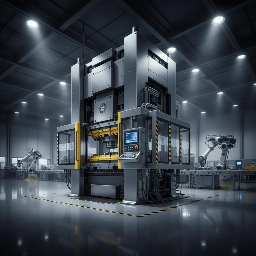
Elemente esențiale ale presei de ambutisare și ale echipamentului pentru scule
Așadar, ați selectat materialul și metoda de decupare — dar ce se întâmplă cu mașina care efectuează lucrarea propriu-zisă? Iată realitatea: chiar și cea mai bună proiectare a matriței, combinată cu materialul optim, nu va produce piese de calitate dacă presa dvs. de decupare metalică nu este potrivită pentru această sarcină. Înțelegerea mașinilor de decupare și a capacităților acestora este esențială pentru oricine ia decizii legate de producție.
Ce este, de fapt, o presă de decupare? Gândiți-vă la ea ca la o sursă de putere care transformă energia într-o forță precis controlată, determinând sculele dvs. să pătrundă în foile de metal pentru a crea componente finite. Totuși, nu toate presele funcționează în același mod — iar alegerea unui tip incorect poate duce la pierderi de energie, calitate slabă a pieselor sau deteriorarea costisitoare a echipamentului.
Selectarea între prese mecanice și hidraulice
Cele două tehnologii dominante de prese aduc fiecare avantaje distincte operațiunii dvs. de decupare. Alegerea dintre ele depinde în mare parte de ce anume fabricați și cât de repede trebuie să o faceți.
Prese mecanice de decupare
Aceste lucrătoare domină podelele de producție de înalt volum. Conform JVM Manufacturing, presele mecanice de ambutisare folosesc volanți pentru stocarea și transferul energiei, atingând un număr ridicat de curse pe minut — ceea ce le face ideale pentru serii mari de producție, unde timpul înseamnă bani.
De ce este atât de importantă viteza? O presă mecanică poate funcționa la 200–1.500 de curse pe minut, în funcție de dimensiune și aplicație. La aceste rate, piesele se produc în fracțiuni de secundă. Pentru suporturi auto, terminale electrice sau orice alt component necesar în cantități masive, acest debit se traduce direct în costuri mai mici pe piesă.
Compromisul? Preselor mecanice le este specifică o lungime fixă a cursei și un profil fix al forței. Batișul parcurge același ciclu de mișcare, cursă după cursă — ceea ce este excelent pentru consistență, dar limitativ atunci când este nevoie să ajustați parametrii de deformare în timp real. Simplitatea lor implică întreținere redusă și operare mai ușoară, ceea ce explică popularitatea lor continuă, în ciuda tehnologiilor mai noi.
Exist două configurații principale în presele mecanice de ambutisare:
- Prese cu cadru în formă de C (cadru deschis) – Au o structură deschisă, permițând operatorilor acces ușor din trei părți. Sunt foarte potrivite pentru asamblarea pieselor mici, operațiunile ușoare de ambutisare și aplicațiile care necesită schimbări rapide ale matrițelor.
- Prese cu cadru în formă de H (cu laturi drepte) – Ofertă o rigiditate și o rezistență superioară datorită designului lor cu patru colțuri. Sunt mai potrivite pentru operațiuni de înaltă capacitate de forță și pentru sarcini care necesită formare precisă și repetată.
Prese hidraulice de ambutisare
Când precizia și flexibilitatea sunt mai importante decât viteza brută, intră în scenă presele hidraulice de ambutisare a metalelor. Aceste mașini folosesc cilindri hidraulici pentru a genera forța, permițând operatorilor să controleze presiunea pe întreaga cursă — nu doar la punctul mort inferior.
Imaginați-vă formarea unei forme de cupă obținută prin tragere profundă. Materialul necesită o presiune constantă pe măsură ce curge în cavitatea matriței, nu o singură lovitură de forță. Conform JVM Manufacturing, presele hidraulice mențin o forță constantă pe întreaga cursă, făcându-le ideale pentru sarcini de înaltă precizie, cum ar fi formarea unor forme complicate sau prelucrarea materialelor delicate.
Posibilitatea de reglare se extinde dincolo de controlul forței. Lungimea cursei, timpul de staționare (perioada în care pistonul rămâne în poziția inferioară) și viteza de apropiere pot fi toate modificate fără modificări mecanice. Această adaptabilitate se dovedește deosebit de valoroasă în operațiunile care produc piese variate sau în cele care implică materiale dificile, necesitând secvențe de formare atente.
Limitarea? Viteza. Presele hidraulice funcționează, de obicei, mai lent decât omologii lor mecanici — uneori semnificativ mai lent. Pentru aplicațiile în care precizia este prioritară față de productivitate, acest compromis este justificat. Pentru piese de mare volum, destinate pieței de masă, acest lucru este rar cazul.
Înțelegerea cerințelor de tonaj
Fiecare operațiune de ambutisare necesită o anumită cantitate de forță—măsurată în tone—pentru a fi finalizată cu succes. Dacă subestimați nevoile de tonaj, veți deteriora echipamentul sau veți produce piese defectuoase. Dacă supraestimați în mod semnificativ, cheltuiți inutil capital pentru o capacitate pe care nu o veți folosi niciodată.
Conform Resurse de producție , tonajul reprezintă forța pe care presa este concepută să o exercite asupra semifabricatului în matriță, specificată la o distanță deasupra punctului inferior al cursei. Pentru majoritatea presei mecanice de până la 45 de tone, această valoare se aplică la o distanță de 1/32" până la 1/16" față de punctul mort inferior.
Cum se calculează tonajul necesar? Pentru operațiunile simple de decupare, înmulțiți perimetrul tăieturii cu grosimea materialului și cu rezistența la forfecare a materialului. De exemplu, o piesă rotundă cu diametrul de 6 inch din oțel moale cu grosimea de 0,125" necesită aproximativ 59 de tone, conform formulei: diametru × π × grosime × 25 (pentru oțel moale).
Dar iată ce surprinde inginerii: matrițele progresive necesită însumarea forțelor de la toate stațiile, plus o capacitate suplimentară pentru variabile precum fluctuațiile durității materialului și uzura matriței. Majoritatea operațiunilor specifică prese cu o capacitate cu 20–30 % superioară cerințelor calculate — o marjă de siguranță care previne suprasolicitarea în condiții normale de variație a producției.
O presă de ambutisat din oțel cu o capacitate nominală de 200 de tone poate părea adecvată pentru o sarcină calculată la 150 de tone. Totuși, dacă acest calcul nu a luat în considerare toate operațiunile simultane sau dacă materialul este ușor mai dur decât specificația, vă aflați brusc într-o situație de funcționare la limita capacității sau chiar peste aceasta — ceea ce accelerează uzura și implică riscul unui eșec catastrofal.
Avantajele moderne ale preselor cu servo-acționare
Ce s-ar întâmpla dacă ați putea combina viteza presei mecanice cu flexibilitatea celor hidraulice? Presa de ambutisat cu acționare servo reprezintă ultima frontieră a tehnologiei de ambutisare, utilizând motoare servo programabile pentru a controla mișcarea batiului cu o precizie excepțională.
Conform declarațiilor JVM Manufacturing, presele acționate cu servomotoare permit producătorilor să controleze cu precizie fiecare aspect al mișcării presei, de la viteză până la poziție—permițând operații complexe care anterior erau dificil de realizat sau chiar imposibil de executat cu presele tradiționale.
Gândiți-vă la posibilități: puteți programa batișul să încetinească în etapele critice ale formării, să rămână o fracțiune de secundă într-o poziție fixă pentru a permite curgerea materialului, apoi să accelereze în porțiunile mai puțin solicitate ale cursei. Acest profil de mișcare programabil optimizează fiecare operațiune individual, în loc să forțeze toate operațiunile să se adapteze unui singur ciclu mecanic.
Avantajul privind eficiența energetică surprinde adesea persoanele noi în domeniu. Spre deosebire de presele mecanice, care antrenează continuu volanții, servomotoarele funcționează doar atunci când este necesar. Aceasta reduce semnificativ consumul de energie—având beneficii atât pentru costurile de exploatare, cât și pentru impactul asupra mediului.
Bariera investiției? Costuri inițiale mai mari și necesitatea unei configurări și a unei expertize în programare mai sofisticate. Totuși, pentru producătorii care caută avantaje competitive în ceea ce privește precizia, flexibilitatea și eficiența, tehnologia servo reprezintă din ce în ce mai mult calea de urmat.
Componente esențiale ale matriței
Deși presa furnizează puterea, matrița determină ce anume produce această putere. Conform ghidului complet al U-Need privind componentele matrițelor, matrița de ambutisare este elementul vital al producției în masă, iar proiectarea, materialul și integritatea componentelor individuale determină performanța generală și durata de funcționare.
Înțelegerea acestor componente de lucru vă ajută să apreciați modul în care specificațiile echipamentelor se corelează cu calitatea pieselor:
- Unelte de lovitură – Componenta masculină care efectuează operațiunile de perforare, decupare sau deformare. Confecționată din oțel pentru scule tratat termic sau din carburi, poansonul trebuie să reziste la impacturi repetate, păstrând în același timp dimensiuni precise.
- Blocul matriței (butonul matriței) – Contrapartea feminină a matriței în operațiunile de decupare. Un component prelucrat cu precizie, având un profil de orificiu care corespunde exact matriței, plus o joc calculat cu atenție pentru tăierea curată.
- Placă de desprindere – Elimină materialul de pe matriță în momentul retragerii acesteia. Fără o forță adecvată de desprindere, piesele rămân lipite de matrițe, provocând alimentare necorespunzătoare, deteriorare sau oprirea producției.
- Penele de ghidare și bușoane – Sistemul de aliniere cu precizie care asigură întâlnirea exactă, conform proiectării, a celor două jumătăți ale matriței (superioară și inferioară). Aceste componente, realizate din materiale călite și rectificate cu precizie, previn dezalinierea care distruge matrițele și generează rebuturi.
După cum subliniază U-Need, erori mici de câțiva micrometri la nivelul unui singur component pot declanșa un lanț de defecțiuni: dimensiuni incorecte ale pieselor, uzură prematură a matrițelor, opriri nescheduleate costisitoare și rate ridicate de rebuturi. Această interconexiune dintre precizia echipamentelor și rezultatele producției explică de ce operațiunile de ambutisare de succes investesc semnificativ în matrițe de calitate și în întreținerea corespunzătoare.
| Tipul de presă | Capacitatea de Viteză | Controlul forței | Cele mai bune aplicații | Limită esenţială |
|---|---|---|---|---|
| Mecanic | Ridicată (200–1.500+ SPM) | Profil de cursă fix | Piese cu volum mare și repetitive | Flexibilitate limitată pentru formare complexă |
| Hidraulic | Moderat la scăzut | Forță variabilă pe întreaga cursă | Tragere profundă, formare precisă, producție variată | Timpi de ciclu mai lenti |
| Acționare servo | Programabil | Mișcare complet programabilă | Operații complexe, producție mixtă, lucrări de precizie | Investiție inițială mai mare |
Legătura dintre echipamente și calitate funcționează în ambele sensuri. Alegerea corectă a presei și întreținerea acesteia permit o producție constantă. O capacitate insuficientă sau un instrumentar uzat generează defecțiuni care se propagă în întreaga operațiune. Înțelegerea acestei relații — și investiția corespunzătoare atât în prese de ambutisat, cât și în sistemele de instrumentar — face diferența între operațiunile de ambutisat de clasă mondială și cele care întâmpină dificultăți.
Chiar și cu o selecție optimă a echipamentelor, problemele apar inevitabil în timpul producției. Cunoașterea modului de identificare, diagnosticare și corectare a defectelor frecvente devine o cunoștință esențială pentru oricine conduce operațiuni de ambutisat.
Diagnosticarea defectelor frecvente și strategiile de control al calității
Presa dumneavoastră funcționează, piesele circulă — și apoi o observați. O fisură care se formează în racordul colțului. Muchii ascuțite care se prind de mănușele dumneavoastră de inspecție. Dimensiuni care se abat din toleranță. Vă sună cunoscut? Orice operație de ambutisare a metalelor întâlnește defecțiuni, dar ceea ce diferențiază producătorii de succes de cei care întâmpină dificultăți este capacitatea de a diagnostica rapid problemele și de a aplica măsuri corective eficiente.
Iată realitatea: defecțiunile din piesele metalice ambutisate nu apar aleatoriu. Ele urmează anumite tipare, determinate de comportamentul materialului, starea sculelor și parametrii procesului. Înțelegerea acestor tipare transformă depistarea problemelor dintr-o activitate bazată pe presupuneri într-un proces sistematic de rezolvare a problemelor. Să creăm împreună o resursă completă pentru identificarea, corectarea și prevenirea celor mai frecvente defecțiuni de ambutisare.
Diagnosticarea defecțiunilor de suprafață
Problemele de calitate ale suprafeței indică adesea probleme mai profunde din cadrul procesului de ambutisare a metalelor. Detectarea acestora la timp previne apariția unor defecțiuni de calitate mai grave în etapele ulterioare.
Încrețirea
Când materialul în exces nu are unde să meargă în timpul formării, acesta se îndoaie și se pliază, generând ondulări care afectează atât aspectul, cât și funcționalitatea. Conform ghidului complet de defecțiuni al DR Solenoid, ondularea apare, de obicei, la marginile flanșelor în timpul operațiunilor de tragere, indicând o forță insuficientă a dispozitivului de fixare a semifabricatului sau raporturi de tragere excesive.
Ce cauzează ondularea în piesele dvs. metalice stampilate? Luați în considerare următorii factori:
- Forța dispozitivului de fixare a semifabricatului este prea mică — materialul curge prea liber
- Raportul de tragere depășește capacitatea materialului (raportul adâncime/diametru > 2,5)
- Distribuția incorectă a lubrifiantului, care permite un curgere neuniformă a materialului
- Raza matriței este prea mare, oferind un control insuficient asupra materialului
Soluția? Măriți treptat forța dispozitivului de fixare a semifabricatului până când ondularea dispare, fără a provoca fisurări. În cazurile severe, luați în considerare tragerea în etape, cu operații intermediare de recoacere pentru a restabili ductilitatea materialului între etape.
Fisurare
Nimic nu strică mai repede un ciclu de producție decât fisurarea pieselor în timpul formării. Fisurile apar, de obicei, în colțuri, la margini sau în zonele cu întindere maximă — indicând exact locurile în care au fost depășite limitele materialelor.
DR Solenoid observă că fisurarea poate fi cauzată de rezistența insuficientă la oc a materialului în sine, de parametri incorecți ai procesului de ambutisare, cum ar fi viteza excesivă de ambutisare, sau de un rază prea mică la colțurile matriței. Când efortul aplicat materialului depășește limita sa de rezistență în timpul ambutisării, apar fisuri.
Cauzele fundamentale ale fisurării în componentele metalice ambutisate includ:
- Raze prea mici la colțurile matriței (recomandare: R ≥ 4 × grosimea materialului)
- Ductilitatea materialului insuficientă pentru deformarea necesară
- Ecruisarea din operațiunile anterioare, care reduce formabilitatea rămasă
- Forța excesivă a dispozitivului de fixare a semifabricatului, care restricționează curgerea necesară a materialului
- Viteza de ambutisare prea mare pentru caracteristicile de răspuns ale materialului
Soluțiile implică mărirea razelor matricelor, acolo unde este posibil, selectarea unor calități de material mai ductile sau adăugarea unui recoct la stadiul intermediar pentru a elimina ecruisarea. Pentru oțelurile înalte la rezistență, deformarea la cald la temperaturi de 200–400 °C poate fi necesară pentru a obține formele cerute fără fisurare.
Rănițuri și deteriorări ale suprafeței
Defectele estetice pot părea minore comparativ cu defecțiunile dimensionale, dar indică adesea probleme legate de scule care se vor agrava. Conform DR Solenoid, rănițurile apar atunci când materiale străine contaminează suprafața matricei, atunci când rugozitatea suprafeței nu îndeplinește cerințele sau atunci când apare frecarea în timpul alunecării relative dintre material și matrice.
Strategii de prevenire includ:
- Prelucrarea prin polizare a suprafețelor matricelor până la o rugozitate Ra de 0,2 μm sau mai bună
- Utilizarea uleiurilor pentru ambutisare volatile, care nu lasă reziduuri
- Curățarea preliminară a materialului pentru eliminarea uleiurilor, prafului și a altor contaminanți
- Înlocuirea plăcilor de presiune din oțel cu variante din nylon pentru piesele din aluminiu
Depanare precizie dimensională
Când piesele dvs. din oțel amprentat măsoară în afara toleranțelor, cauza se datorează rar unui singur factor. Variația dimensională rezultă, de obicei, din interacțiunile dintre uzura sculelor, proprietățile materialului și parametrii procesului.
Retrocedere
Fiecare piesă metalică formată tinde să revină elastic către starea sa inițială plană. Controlul acestei reveniri elastice determină dacă operația dvs. de amprentare metalică de calitate îndeplinește toleranțele sau generează deșeuri.
Conform DR Solenoid, eliberarea neuniformă a tensiunilor în material, distribuția neadecvată a forței de fixare și organizarea incorectă a procesului, care conduce la acumularea tensiunilor, contribuie toate la apariția fenomenului de revenire elastică (springback).
Strategii de compensare eficiente:
- Îndoirea excesivă peste unghiurile țintă pentru a compensa revenirea elastică
- Utilizarea simulărilor CAE pentru a prezice revenirea elastică și pentru a ajusta corespunzător profilul matrițelor
- Adăugarea unor procese de modelare cu o presiune puternică de 0,05–0,1 mm după formarea inițială
- Optimizarea direcției de dispunere — alinierea îndoirilor cu direcția de laminare a materialului reduce revenirea elastică
- Reglarea distribuției forței de fixare a semifabricatului pe mai multe zone
Pentru problemele de răsucire, DR Solenoid recomandă adăugarea unei structuri de pre-dobândire cu unghi negativ la matriță — pentru a contracara tendința naturală a materialului de a reveni în poziția inițială.
Bavuri
Muchiile ascuțite și proeminențele materialelor de-a lungul liniilor de tăiere indică probleme la operațiunile de tăiere. În afară de problemele estetice, buruienii excesivi (înălțime > 0,1 mm) creează riscuri în manipulare, interferențe la asamblare și pot duce la defecțiuni în exploatare.
Conform Ghidul de inspecție calitativă al Metal Infinity , buruienii excesivi pot tăia mâinile, zgâria aspectul suprafeței și pot indica starea de uzură a matriței, care se va agrava fără intervenție.
Ce cauzează formarea buruienilor la componentele obținute prin ambutisare metalică?
- Jocul dintre poanson și matriță în afara domeniului optim (ar trebui să fie de 8–12 % din grosimea materialului pentru oțel moale)
- Uzură sau ciupire a muchiei de tăiere
- Proprietățile materialului care variază față de specificație
Măsurile corective includ:
- Înlocuirea regulată a matrițelor de rectificare — DR Solenoid recomandă inspecția la fiecare 50.000 de curse
- Reglarea jocurilor în funcție de tipul materialului (valori mai mici ale jocului pentru materiale mai moi)
- Luarea în considerare a tehnologiei de decupare fină cu suporturi de decupare în formă de V pentru muchii fără bavuri
- Pentru terminalele din cupru, aplicarea decupării cu joc zero elimină în întregime formarea bavurilor
Deriva dimensională
Modificările graduale ale dimensiunilor în cadrul unei serii de producție indică o uzură progresivă a sculelor sau o instabilitate a procesului. Conform ghidului de inspecție al Metal Infinity, un producător a observat, în cadrul inspecțiilor de patrulare, o creștere graduală a dimensiunilor găurilor — care s-a dovedit ulterior a fi cauzată de uzura colților de ghidare ai matriței. Fără monitorizarea în timpul procesului, întreaga serie de 20.000 de produse ar fi putut fi rebutată.
Măsurile de control al procesului pentru stabilitatea dimensională includ:
- Inspeții periodice de patrulare (verificarea a 5 piese la fiecare 30 de minute în timpul producției)
- Inspeția primului articol înainte de fiecare serie de producție
- Adăugarea colților de ghidare sau a pinilor de poziționare precisă în matrițe
- Urmărirea tendințelor dimensionale prin diagrame de control al proceselor statistice
| Tip defect | Cauzele comune | Măsuri Corective | Măsuri de prevenire |
|---|---|---|---|
| Încrețirea | Forță insuficientă a dispozitivului de fixare a semifabricatului; raport de tragere excesiv; ungere neuniformă | Măriți forța dispozitivului de fixare a semifabricatului; utilizați tragerea în etape; optimizați ungerea | Simulare CAE în timpul proiectării matriței; comandă cu control multi-punct al forței dispozitivului de fixare a semifabricatului |
| Fisurare | Raza matriței prea mică; ductilitatea materialului insuficientă; îmbătrânire excesivă prin deformare | Măriți raza matriței (R ≥ 4t); aplicați recoacere intermediară; utilizați formarea la cald pentru oțelurile înalt rezistente | Testarea materialului înainte de producție; proiectarea corectă a secvenței de deformare |
| Retrocedere | Eliberare neuniformă a tensiunilor; forță de strângere inadecvată; tensiuni acumulate | Compensare pentru supradosare; adăugați un proces de finisare; ajustați direcția de dispunere | Simulare CAE a revenirii elastice; structuri de pre-dobândire cu unghi negativ |
| Bavuri | Joc incorect între poanson și matriță; uzură a muchiei de tăiere; variație a materialului | Reglați jocul la 8–12% din grosimea materialului; rectificați matrițele; luați în considerare decuparea fină | Inspecție periodică a matrițelor la fiecare 50.000 de curse; tehnologie de acoperire (TiAlN) |
| Șurseale | Suprafață contaminată a matriței; finișare rugoasă a suprafeței; lubrifiere insuficientă | Polați matrița până la Ra 0,2 μm; utilizați ulei de ambutisaj volatil; curățați în prealabil materialul | Placare cu crom sau tratament TD aplicat matrițelor; inspecție a suprafeței materialului |
| Variație dimensională | Uzură a matriței; uzură a colților de ghidare; abatere a grosimii materialului; nealinieri a presei | Înlocuiți componentele uzate; recalibrați paralelismul presei; precizați mai riguros specificațiile pentru material | Monitorizare SPC; inspecție de rutină; înregistrare a duratei de viață a matriței |
| Grosime neuniformă | Blocare a curgerii materialului; frecare excesivă; rază a matriței prea mică | Optimizați dispunerea benzilor de tragere; aplicați lubrifiant cu vâscozitate ridicată local; utilizați un material mai ductil | Proiectare echilibrată a curgerii materialului; strategie adecvată de ungere |
Întreținere preventivă pentru asigurarea calității constante
Diagnosticul reactiv rezolvă problemele imediate, dar abordările preventive împiedică apariția defectelor înainte ca acestea să se producă. Integrarea sistematică a controlului calității în procesul de fabricare a pieselor metalice ambutisate aduce beneficii sub formă de reducerea deșeurilor, a plângerilor clienților și a programărilor mai previzibile ale livrărilor.
Metode de inspecție dimensională
Conform Metal Infinity, toleranța dimensională pentru piesele ambutisate se situează adesea în jurul valorii ±0,05 mm — echivalentul grosimii a două foi de hârtie A4. Detectarea variațiilor atât de mici necesită instrumente de măsurare adecvate și abordări sistematice:
- Șubleri vernier și micrometre – Verificări rapide ale dimensiunilor accesibile în timpul inspecțiilor de rutină
- mașini de măsurare 2,5D – Sisteme bazate pe video pentru dimensiuni plane precise și diametre ale găurilor
- Mașini de măsurare a coordonelor (CMM) – Verificare completă în 3D pentru dimensiunile critice și geometriile complexe
- Măsurători GO/NO-GO – Verificări funcționale rapide în timpul producției de mare volum
Evaluarea calității suprafeței
Inspecia vizuală rămâne fundamentală, dar standardizarea procesului îmbunătățește consistența:
- Efectuați inspecția în condiții de iluminare controlată — Metal Infinity recomandă o cutie de iluminare cu unghi de vizualizare de 45 de grade
- Utilizați mostre standard „OK/NG” pentru compararea buruienilor, fisurilor și zgârieturilor
- Folosiți microscoape pentru examinarea defectelor de suprafață care nu sunt vizibile cu ochiul liber
- Documentați defectele prin fotografii pentru analiza cauzelor profunde
Controlul Statistic al Proceselor
Puterea reală a stampilării calitative a metalelor constă în utilizarea datelor pentru a prezice și preveni problemele. Conform Metal Infinity, pe baza statisticilor pe termen lung, se poate stabili indicele de capabilitate al procesului (CPK) pentru o piesă; dacă CPK scade sub 1,33, acest lucru indică o randament instabil, necesitând ajustări ale procesului.
O implementare eficientă a controlului statistic al proceselor (SPC) include:
- Înregistrarea continuă a datelor dimensionale în timpul producției
- Trasarea diagramelor de control (diagrame X-bar/R) pentru identificarea tendințelor înainte ca acestea să depășească toleranțele
- Stabilirea limitelor de acțiune care declanșează investigația înainte de atingerea limitelor de respingere
- Transmiterea datelor de inspecție înapoi către inginerie, pentru proiectarea matrițelor și îmbunătățirea procesului
DR Solenoid subliniază importanța acestui ciclu de feedback: când piesele obținute prin ambutisare metalică întâmpină probleme de calitate, se efectuează o analiză detaliată a cauzelor, se elaborează soluții practice și se păstrează înregistrări precise ale procesului. Se transmit înapoi problemele cheie pentru a preveni reapariția acelorași probleme.
Protocoale de întreținere a matrițelor
Echipamentul dumneavoastră este un activ care se degradează — fiecare cursă îl apropie mai mult de defectare. Întreținerea sistematică prelungește durata de viață a matriței, menținând în același timp calitatea pieselor:
- Întocmirea înregistrărilor privind durata de viață a matriței, urmărind numărul de curse și istoricul întreținerii
- Programarea inspecțiilor regulate ale pieselor supuse uzurii (matrice, manșoane ghid, muchii de tăiere)
- Aplicarea tehnologiilor de acoperire, cum ar fi TiAlN, pentru îmbunătățirea rezistenței la uzură
- Stocarea loturilor diferite de materiale separat, pentru a preveni amestecarea
- Documentați toate acțiunile de întreținere pentru analiza tendințelor
Valoarea reală a inspecției nu constă în eliminarea produselor defecte, ci în îmbunătățirea proceselor și construirea încrederii prin date.
Controlul calității în stampilarea metalică nu este un singur punct de verificare — este un sistem integrat care acoperă verificarea materialelor primite, monitorizarea în timpul procesului, inspecția pieselor finite și bucla de feedback pentru îmbunătățirea continuă. Producătorii care stăpânesc acest sistem transformă calitatea dintr-un centru de cost într-un avantaj competitiv.
Acum că strategiile de depistare a defecțiunilor și de control al calității au fost stabilite, vă puteți întreba cum se compară stampilarea cu alte metode de fabricație — și când este cea mai potrivită fiecare abordare pentru cerințele specifice ale dumneavoastră.
Stampilarea metalică versus alte metode de fabricație
Așadar, v-ați stăpânit fluxul de lucru al ștanțării, ați selectat materialele și înțelegeți controlul calității — dar iată o întrebare care merită o analiză sinceră: este ștanțarea, de fapt, alegerea potrivită pentru proiectul dumneavoastră? Uneori răspunsul este da. Alteori nu este. A cunoaște momentul potrivit pentru a utiliza ștanțarea din foaie de metal, comparativ cu alte procese alternative, vă poate economisi mii de dolari și luni întregi de timp de dezvoltare.
Gândiți-vă la metodele de fabricație ca la uneltele dintr-un atelier. Un ciocan este excelent pentru bătutul cuielelor, dar e complet inadecvat pentru tăierea lemnului. În mod similar, fiecare proces de deformare a metalelor are aplicații ideale — iar impunerea unei metode nepotrivite unui proiect generează costuri inutile, probleme de calitate sau ambele. Să comparăm ștanțarea cu principalele alternative, astfel încât să puteți lua decizii informate.
Economia ștanțării versus prelucrarea prin așchiere
Prelucrarea prin frezare CNC și ambutisarea reprezintă abordări fundamental diferite pentru realizarea pieselor din metal. Prelucrarea elimină material din blocuri solide; procesul de presare a metalelor reconfigurează materialul sub formă de foaie fără o îndepărtare semnificativă a acestuia. Această diferență determină variații importante în structura costurilor și în potrivirea aplicațiilor.
Când este mai indicată prelucrarea prin frezare CNC?
- Volume mici de producție – Conform Ghidului de fabricație Gizmospring , prelucrarea prin frezare CNC este ideală pentru aplicațiile care necesită precizie ridicată și serii mici de producție, unde investiția în scule nu se justifică.
- Geometrii complexe în 3D – Piesele care necesită degajări, caracteristici interne sau forme imposibil de obținut din foaie plană
- Toleranțe strânse pe materiale groase – Prelucrarea menține acuratețea pe întreaga secțiune transversală semnificativă a materialului
- Dezvoltarea prototipurilor – Nu există timp de așteptare pentru realizarea matrițelor, ceea ce înseamnă obținerea pieselor în câteva zile, nu săptămâni
Când este avantajoasă ambutisarea?
- Producție de volum mare – Odată ce costurile matrițelor sunt amortizate, costul pe piesă scade dramatic
- Piese derivate din geometria foilor metalice – Suporturi, carcase, panouri și componente similare
- Cerințe de viteză – Sute sau mii de piese pe oră, comparativ cu minute pe piesă
- Eficiența materialelor – Ambutisarea foilor metalice generează, de obicei, mai puține deșeuri decât prelucrarea prin strunjire a blocurilor solide
Punctul de trecere variază în funcție de complexitatea piesei, dar, în general, se situează între 1.000 și 5.000 de unități. Sub acest interval, flexibilitatea prelucrării mecanice depășește, de obicei, investiția necesară pentru realizarea matrițelor. Peste acest interval, eficiența economică pe piesă a ambutisării devine foarte avantajoasă.
Tăierea cu laser: flexibilitate fără matrițe
Ce s-ar întâmpla dacă ați putea începe producția imediat, fără a aștepta săptămâni pentru realizarea matrițelor? Tăierea cu laser oferă exact acest lucru: fișierele digitale se transformă în piese tăiate în câteva ore, fără a fi necesară proiectarea, fabricarea sau întreținerea unor matrițe.
Conform Comparația detaliată a lui Hotean , tăierea cu laser oferă o reducere a costurilor de 40% față de ambutisare pentru serii sub 3.000 de bucăți, eliminând costurile de dotare în valoare de peste 15.000 USD și obținând o precizie de ±0,1 mm comparativ cu toleranța de ±0,3 mm specifică ambutisării.
Avantajele tăierii cu laser:
- Investiție zero în matrițe – Începeți imediat tăierea direct din fișierele CAD
- Flexibilitate în proiectare – Modificările nu au niciun cost; actualizați pur și simplu programul digital
- Precizie Superioară – Toleranță de ±0,1 mm comparativ cu toleranța tipică de ±0,3 mm pentru ambutisare
- Contururi complexe – Forme intricate care ar necesita matrițe progresive scumpe
Hotean subliniază că o serie de producție de 500 de suporturi HVAC a demonstrat rezultate remarcabile: suporturile tăiate cu laser au asigurat o potrivire perfectă (100 %) la asamblare, fără necesitatea unor ajustări, în timp ce suporturile ambutisate au necesitat modificări manuale la 65 de bucăți (rată a defectelor de 13 %).
Cazurile în care ambutisarea rămâne avantajoasă:
- Volum care depășește 3.000–5.000 de unități – Costurile de prelucrare pe piesă favorizează ambutisarea
- cerințe de formare 3D – Tăierea cu laser produce doar piese plane; o presă pentru tablă produce îndoiri, tragere și formare
- Restricții legate de grosimea materialului – Tăierea cu laser devine lentă și costisitoare la grosimi peste 6–10 mm
- Cerințe privind timpul de ciclu – Ambutisarea produce piese în fracțiuni de secundă; tăierea cu laser durează minute pe piesă
Ideea-cheie? Tăierea cu laser și ambutisarea nu sunt întotdeauna concurente — sunt adesea complementare. Mulți producători folosesc tăierea cu laser pentru prototipuri și serii mici, apoi trec la utilajele de ambutisare după ce proiectele au fost validate și volumul justifică investiția.
Când procesele alternative sunt potrivite
Turnare: Forme complexe, proprietăți diferite
Presarea și turnarea metalelor rezolvă probleme diferite. Turnarea implică turnarea metalului topit în matrițe, creând piese cu geometrii interne complexe, grosimi variabile ale pereților și forme imposibil de realizat din foi plane.
Alegeți turnarea atunci când:
- Piesele necesită cavități interne sau forme 3D complexe
- Grosimea pereților variază semnificativ pe întreaga componentă
- Proprietățile materialelor, cum ar fi amortizarea sau rezistența la căldură, sunt mai importante decât raportul rezistență-masă
- Volumul producției justifică investiția în matrițe, dar nu necesită vitezele de ambutisare
Totuși, turnarea oferă în mod obișnuit rapoarte rezistență-masă mai reduse decât piesele ambutisate, necesită un număr mai mare de operații secundare de finisare și produce piese cu o precizie dimensională mai puțin constantă. Pentru componente structurale din tablă metalică, ambutisarea oferă în general o performanță superioară.
Forjare: Rezistență superioară, aplicații diferite
Când rezistența absolută este cel mai important factor, forjarea creează piese cu proprietăți mecanice superioare. Acest proces comprimă metalul sub presiune extremă, aliniind structura granulară și eliminând golurile interne — producând componente care depășesc atât variantele realizate prin ambutisare, cât și cele prelucrate prin așchiere în aplicații solicitante.
Conform Gizmospring, turnarea și forjarea oferă soluții durabile pentru industriile grele, cum ar fi cea auto — dar fiecare îndeplinește scopuri distincte. Forjarea este deosebit de potrivită pentru:
- Componente critice pentru siguranță, care necesită rezistență maximă (arbore cotit, biele)
- Piese supuse unor eforturi ciclice ridicate
- Aplicații în care consecințele unei defecțiuni sunt grave
Compromisul? Forjarea este mai costisitoare decât ambutisarea, necesită echipamente și expertiză diferite și produce piese cu dimensiuni mai puțin precise, care, în general, necesită o prelucrare secundară prin așchiere. Pentru majoritatea aplicațiilor din tablă, ambutisarea asigură o rezistență adecvată la un cost mai scăzut.
Abordări hibride de fabricație
Iată ce înțeleg producătorii experimentați: alegerea dintre procese nu este întotdeauna o decizie de tip „fie/ fie”. Abordările hibride oferă adesea cele mai bune rezultate, combinând punctele forte ale diferitelor procese.
Strategii hibride frecvente:
- Tăiere cu laser + ambutisare – Semifabricate tăiate cu laser alimentate în matrițe de deformare pentru operații de îndoire și tragere
- Ambutisare + prelucrare mecanică – Componente de bază ambutisate, cu elemente prelucrate mecanic acolo unde toleranțele impun acest lucru
- Ambutisare + sudură – Mai multe piese ambutisate asamblate prin sudură în ansambluri mai mari sau mai complexe decât ar permite o singură piesă obținută prin ambutisare
Procesul de prelucrare a tablei pe care îl alegeți trebuie să corespundă combinației specifice de volum, geometrie, toleranțe și cerințe bugetare — nu să forțeze proiectul dumneavoastră într-o abordare de fabricație predeterminată.
Compararea proceselor: Alegerea corectă
| Factor | Ștampilare | Frezare CNC | Tăierii cu laser | TURNARE | Forjare |
|---|---|---|---|---|---|
| Volum ideal | 5.000+ unități | 1–500 de bucăți | 1–3.000 de bucăți | 500–50.000 de bucăți | 100–10.000 de bucăți |
| Investiție în scule | $10,000-$50,000+ | Minim (elemente de fixare) | Niciunul | $5,000-$30,000 | $10,000-$100,000+ |
| Timp de livrare (prima bucată) | 4-8 săptămâni | Zile | Ore până la zile | 4-12 săptămâni | 6–16 săptămâni |
| Toleranță tipică | ±0,1-0,3 mm | ±0,01–0,05 mm | ±0,1 mm | ±0,5-1,0 mm | ±0,5–2,0 mm |
| Cost pe bucată la volum mare | Cel mai jos | Cel mai înalt | Moderat | Moderat | Ridicat |
| Geometrie a piesei | Forme derivate din foile de material | Orice formă 3D | Doar profile plate | Forme 3D complexe | 3D simplu până la moderat |
| Modificări ale designului | Costisitor (dotare nouă) | Ușor (reprogramare) | Gratuit (actualizare fișier) | Costisitor (matrice nouă) | Foarte scump |
| Cele mai bune aplicații | Suporturi, panouri, carcase, terminale | Prototipuri, piese complexe, volum mic | Prototipuri, piese plate, designuri variate | Carcase, blocuri motoare, componente interne complexe | Arbori cu manete, roți dințate, componente supuse la eforturi ridicate |
Factorii cheie de decizie de luat în considerare:
- Volumul de producție – Sub 1.000 de bucăți, evitați investiția în matrițe pentru ambutisare. Peste 10.000 de bucăți, economia ambutisării devine atrăgătoare.
- Geometrie a piesei – Dacă proiectul dumneavoastră pornește de la tablă metalică și necesită îndoire, tragere sau deformare, ambutisarea este metoda concepută special pentru această sarcină.
- Urgența termenului de livrare – Aveți nevoie de piese în câteva zile? Tăiere cu laser sau prelucrare mecanică. Puteți aștepta 4–8 săptămâni? Matrițele pentru ambutisare oferă valoare pe termen lung.
- Stabilitatea proiectului – Modificările frecvente favorizează procese flexibile; proiectele stabile justifică investiția în matrițe.
- Cerințe privind Toleranțele – Dimensiunile critice sub ±0,1 mm pot necesita prelucrare mecanică sau ambutisare fină, nu ambutisarea standard.
Procesul de presare a metalelor se remarcă prin ceea ce este conceput să realizeze: producția în volum mare a pieselor obținute din tablă, cu calitate constantă și eficiență costurilor la scară largă. Totuși, impunerea ambutisării în aplicații mai potrivite altor metode duce la pierderi financiare și creează provocări inutile privind calitatea.
Înțelegerea acestor compromisuri vă pune într-o poziție favorabilă pentru a lua decizii informate privind producția — și pentru a colabora eficient cu furnizorii care vă pot ghida către abordarea optimă pentru cerințele specifice ale dumneavoastră.
Selectarea partenerului potrivit pentru operarea de ambutisare pentru proiectul dumneavoastră
Ați stăpânit fundamentalele tehnice — operațiile, materialele, echipamentele și controlul calității. Dar iată o adevăr care surprinde mulți ingineri: succesul proiectului dumneavoastră de ambutisare depinde în aceeași măsură de partenerul de producție pe care îl alegeți, precum și de proiectarea dumneavoastră. Alegerea unui furnizor nepotrivit duce la nerespectarea termenelor limită, scăpări de calitate și redesignuri costisitoare. Alegerea celui potrivit? Aceasta transformă proiectul dumneavoastră dintr-unul stresant într-unul fără probleme.
Indiferent dacă aveți nevoie de servicii personalizate de ambutisare a metalelor pentru lansarea unui nou produs sau de ambutisare precisă a metalelor pentru componente auto critice, procesul de evaluare urmează modele previzibile. Să analizăm împreună criteriile care diferențiază serviciile excepționale de ambutisare a metalelor de cele care vă vor pune într-o situație dificilă.
Evaluarea Capacităților Furnizorului
Nu toți partenerii de ambutisare sunt la fel de buni. Înainte de a solicita oferte de preț, trebuie să înțelegeți ce capacități sunt, de fapt, esențiale pentru cerințele dvs. specifice.
Certificări care semnalează angajamentul față de calitate
Certificările din industrie reprezintă o formă sintetică de evidențiere a sistemelor de calitate și a maturității proceselor. Conform ghidului de selecție a producătorilor al Die-Matic, asigurarea faptului că furnizorii dețin certificări relevante — cum ar fi ISO 9001 și IATF 16949 — constituie o garanție de bază privind procesele de control al calității.
Ce înseamnă, de fapt, aceste certificări?
- ISO 9001 – Cerințe de bază privind sistemul de management al calității, aplicabile în toate industriile
- IATF 16949 – Standarde de calitate specifice industriei auto, impuse de principalele producători auto (OEM) din întreaga lume. Dacă vă ocupați de stampare auto, această certificare nu este opțională — este esențială.
- AS9100 – Cerințe privind sistemul de management al calității pentru domeniul aerospațial, destinate furnizorilor care deservesc piețele aviației și apărării
- ISO 14001 – Certificare privind sistemul de management al mediului, din ce în ce mai importantă pentru programele conștiente din punct de vedere al sustenabilității
În afara certificărilor, Die-Matic subliniază importanța evaluării unor soluții solide pentru inspecție și testare, a consistenței pe loturi mari de producție și a unor sisteme puternice de trasabilitate. Un serviciu de stampare metalică fără o infrastructură robustă de calitate va genera, în cele din urmă, probleme în lanțul dvs. de producție.
Capabilități inginerești și tehnice
Cei mai buni furnizori nu doar exploatează presele — ci rezolvă problemele înainte ca producția să înceapă. Căutați parteneri care oferă:
- Simulare CAE – Inginerie asistată de calculator care previzionează problemele de deformare, revenirea elastică (springback) și curgerea materialului înainte de tăierea oțelului. Această capacitate previne revizuirile costisitoare ale sculelor.
- Prototipare rapida – Conform StampingSimulation , simularea în stadiul prototipului poate fi avansată până la procesul de fabricație în masă, economisind astfel și mai mult timp în etapele ulterioare ale cronogramei proiectului.
- Analiza pentru facilitarea fabricației (DFM) – Ingineri experimentați care pot optimiza proiectul dumneavoastră pentru eficiența ștanțării
- Capacități interne de utilaj – Control asupra proiectării, fabricării și întreținerii matrițelor
Pentru proiectele de ștanțare metalică destinate industriei auto, care necesită atât viteză, cât și precizie, furnizorii precum Shaoyi demonstrează modul în care aceste capacități se combină — oferind certificare IATF 16949, alături de simulări avansate CAE, prototipare rapidă în doar 5 zile și ștanțare metalică în volum mare, cu o rată de aprobare la prima încercare de 93%.
Flexibilitatea și capacitatea de producție
Necesitățile dumneavoastră de volum actuale pot diferi semnificativ de cele viitoare. Ghidul Die-Matic subliniază faptul că, dacă intenționați să aveți nevoie de un număr mai mic sau mai mare de piese în orice moment din viitor, veți dori un partener de ștanțare metalică suficient de flexibil pentru a se adapta corespunzător.
Evaluați potențialii furnizori în funcție de:
- Gama de capacități de presare disponibile (de la lucrări mici de precizie până la deformare masivă)
- Capacitatea de a scala producția de la cantități prototip la producție în volum mare
- Capabilități de operații secundare (sudură, placare, asamblare) care reduc complexitatea lanțului de aprovizionare
- Prezența geografică — producătorii locali sau cei cu facilități amplasate strategic oferă timpi de livrare mai scurți și costuri reduse de transport
Optimizarea proiectării pentru succesul operării de ambutisare
Chiar și cel mai bun furnizor nu poate depăși proiectări fundamental problematice. Aplicarea principiilor proiectării pentru fabricabilitate (DFM) în stadiile timpurii economisește bani, îmbunătățește calitatea și accelerează termenul de livrare.
Conform ghidului DFM al Die-Matic, 70% din costul produsului este stabilit în faza de dezvoltare — dar modificările de inginerie efectuate în timpul fabricației pot crește costurile și pot afecta grav profitabilitatea. Este mult mai eficient din punct de vedere financiar să se realizeze o proiectare holistică încă de la început.
Directive esențiale DFM pentru piesele ambutisate
| Caracteristică | Recomandare DFM | De ce contează |
|---|---|---|
| Diametrul orificiului | ≥ grosimea materialului | Previne ruperea poansoanelor și asigură tăieturi curate |
| Distanța dintre găuri | ≥ 2× grosimea materialului | Previne umflarea materialului între caracteristici |
| Distanța dintre gaură și margine | ≥ 2× grosimea materialului | Păstrează integritatea structurală |
| Gaură lângă zimț | ≥ 1,5 × grosimea + rază de îndoire | Previne deformarea în timpul formării |
| Lățime minimă a flanșei | ≥ 2,5× grosimea materialului | Asigură formarea corectă fără fisurare |
| Rază interioară de îndoire | ≥ grosimea materialului | Previne fisurarea la liniile de îndoire |
| Înălțimea îndoirii | ≥ 2,5 × grosimea + rază de îndoire | Permite angajarea sculelor pentru o formare precisă |
| Rază de colț (semifabricate) | ≥ 0,5 × grosimea materialului | Reduce concentrarea stresului și uzura matriței |
| Adâncimea embosajului | ≤ 3× grosimea materialului | Previne subțierea și fisurarea |
Die-Matic subliniază faptul că inginerii analizează complexitatea piesei și toleranțele acesteia pentru a se asigura că echipamentul lor poate realiza stamparea piesei în mod eficient și poate elimina, acolo unde este posibil, operațiile secundare. Colaborarea strânsă cu partenerul dumneavoastră specializat în stampare metalică personalizată în faza de proiectare vă asigură obținerea unor piese finite care îndeplinesc, în mod rentabil, așteptările.
De la prototip la producție în serie
Drumul de la concept la producția în volum mare implică transferuri critice, în cadrul cărora apar adesea probleme. Structurarea intenționată a acestei etape previne surprizele costisitoare.
Faza de prototipare
Conform StampingSimulation, prototiparea din tablă metalică rămâne necesară pentru fiecare proiect de fabricație, deoarece produsul format din tablă metalică trebuie să provină dintr-un material real de tablă — nu poate fi imprimat în 3D. Toate aceleași provocări ale formării metalului sunt prezente și în stadiul prototipului.
Acesta este exact motivul pentru care simularea este atât de importantă. StampingSimulation subliniază faptul că simularea este mult mai eficientă – atât din punct de vedere al costurilor, cât și al timpului – decât metodele bazate pe încercare și eroare. Simularea procesului de deformare înainte de realizarea piesei prototip previne apariția fisurilor, a ondulațiilor și a revenirii elastice severe, care ar putea compromite termenul de livrare.
Căutați furnizori care oferă:
- Timp scurt de realizare a prototipului (zile, nu săptămâni)
- Proiecte validate prin simulare înainte de încercările fizice
- Feedback colaborativ privind optimizarea proiectului
Listă de verificare pentru calificarea furnizorilor
Înainte de a vă angaja un partener specializat în servicii personalizate de ambutisare metalică, verificați acești factori esențiali:
- Istoricul calității – Solicitați indicatori cantitativi și rate ale defectelor de la clienții actuali
- Stabilitate Financiară – De câți ani activează în domeniu? Ce durată are mandatul conducerii și care este rata de rotire a personalului managerial?
- Relații cu clienții – De cât timp colaborează clienții existenți cu acest furnizor?
- Răspuns rapiditate la comunicare – Die-Matic subliniază faptul că ușurința comunicării este esențială: dorești un partener care să răspundă rapid, să fie accesibil și ușor de colaborat.
- Adâncimea sprijinului ingineresc – Pot ei optimiza proiectele, rezolva rapid problemele și menține proiectele în termen?
Semne de alarmă de evitat
Ghidul Die-Matic pentru selecția producătorilor identifică semnele de alarmă, printre care:
- Calitate nesistematică sau lipsa sistemelor documentate de asigurare a calității
- Comunicare deficitară sau contacte neresponsice
- Imposibilitatea de a furniza referințe de clienți sau indicatori de calitate
- Lipsa certificărilor industriale relevante
- Lipsa sprijinului ingineresc sau a capacităților DFM (Design for Manufacturability)
Selectarea partenerului de fabricație potrivit nu se bazează doar pe preț sau pe capacitate — este vorba despre o parteneriat strategic pe termen lung și aliniere strategică. Un partener nepotrivit duce la întârzieri, rework costisitor și eșecuri ale produselor. Partenerul potrivit asigură calitate, soluții inovatoare și servicii fiabile în permanență.
Industria de ambutisare metalică de precizie oferă nenumărate opțiuni de furnizori — dar procesul de evaluare prezentat aici vă ajută să identificați parteneri capabili să sprijine atât obiectivele imediate ale proiectelor, cât și succesul pe termen lung în producție. Alocați timp pentru a evalua în mod riguros capacitățile, pentru a optimiza proiectele în vederea fabricabilității și pentru a construi relații cu furnizori care demonstrează excelență tehnică și colaborare rapidă și eficientă. Proiectele dvs. de ambutisare vor rula mai fluent, vor costa mai puțin și vor asigura calitatea pe care clienții dvs. o așteaptă.
Întrebări frecvente despre procesul de fabricație prin ambutisare
1. Care este procesul de ambutisare în fabricație?
Stampilarea metalului este un proces de fabricație care transformă foile plane de metal în componente cu forme precise, folosind o forță controlată și utilaje specializate. O presă de stampilare acționează o matriță durificată care pătrunde în foaia de metal pentru a efectua operații precum decuparea, perforarea, îndoirea, tragerea, reliefarea, flanșarea și monedarea. Acest proces implică șapte etape cheie: selecția și pregătirea materialului, proiectarea și ingineria matriței, configurarea și calibrarea presei, alimentarea și poziționarea, cursa de stampilare, evacuarea și manipularea pieselor, precum și inspecția calității. Această metodă domină producția în volum mare din domeniile automotive, aerospace, electronice și electrocasnice, datorită vitezei, consistenței și eficienței costurilor la scară largă.
2. Care sunt cei 7 pași ai metodei de stampare?
Cei șapte pași ai metodei de ambutisare a metalelor includ: (1) Selectarea și pregătirea materialului – evaluarea proprietăților mecanice și pregătirea rolelor prin tăiere, nivelare și curățare; (2) Proiectarea și ingineria matriței – realizarea schemelor de bandă, calculul forțelor și efectuarea simulărilor CAE; (3) Configurarea și calibrarea presei – potrivirea matriței cu presa, stabilirea înălțimii de închidere și programarea parametrilor cursei; (4) Alimentarea și poziționarea – livrarea automatizată a materialului cu aliniere precisă, folosind alimentatoare servo și pini de ghidare; (5) Cursa de ambutisare – ciclul presei în care au loc operațiile de decupare, deformare sau tragere; (6) Ejectarea și manipularea pieselor – îndepărtarea pieselor finite cu ajutorul plăcilor de desprindere și al ejectoarelor; (7) Inspectia calității – măsurarea dimensională, evaluarea suprafeței și verificarea controlului statistic al procesului.
3. Sub ce proces se încadrează ambutisarea?
Stamparea se încadrează în procesele de fabricație prin deformare a foilor metalice. Cunoscută și sub denumirea de presare, aceasta presupune plasarea unei foi metalice plane, fie sub formă de disc (blank) sau sub formă de bandă continuă (coil), într-o presă de stampare, unde o sculă și o matriță îi imprimă metalului noi forme. Procesul cuprinde mai multe tehnici de deformare a metalelor, inclusiv decuparea, perforarea, îndoirea, pășunarea, reliefarea, monedarea și tragerea. Stamparea este clasificată ca un proces de deformare la rece, deoarece are loc, în mod obișnuit, la temperatura camerei, ceea ce o distinge de metodele de deformare la cald, cum ar fi forjarea. Aceasta face parte din categoria mai largă a prelucrării metalelor, alături de procese precum strunjirea, turnarea și sudarea.
4. Care este diferența dintre stamparea cu matrițe progresive, cu matrițe de transfer și cu matrițe compuse?
Stamparea cu matriță progresivă folosește o bandă continuă de metal care se deplasează prin mai multe stații în cadrul unei singure matrițe, fiecare stație efectuând operații diferite în mod simultan — soluție ideală pentru producția în volum mare a pieselor complexe de dimensiuni mici până la medii. Stamparea cu matriță de transfer separă piesa de prelucrat la un stadiu incipient și utilizează degete mecanice pentru a deplasa piese individuale între stații, fiind potrivită pentru componente de dimensiuni mai mari și pentru operațiuni de tragere adâncă. Stamparea cu matriță compusă efectuează mai multe operații de tăiere într-o singură cursă, producând piese plane, cum ar fi șaisprezecele, cu o planitate excepțională și cu costuri mai reduse ale sculelor comparativ cu matrițele progresive. Alegerea depinde de dimensiunea piesei, de complexitatea acesteia, de volumul de producție și de necesitatea efectuării unor operații de deformare în afară de tăiere.
5. Cum alegeți materialul potrivit pentru stamparea metalică?
Selectarea materialului pentru ambutisarea metalică depinde de echilibrul dintre formabilitate, rezistență, rezistență la coroziune și cost. Oțelul carbon și oțelul zincat oferă soluții rentabile pentru piese structurale cu rezistență la tractiune superioară lui 375 MPa. Oțelul inoxidabil (calitățile 304, 409 și 430) asigură rezistență la coroziune, dar necesită o atenție deosebită față de întărirea prin deformare în timpul formării. Aluminiul oferă avantaje legate de reducerea masei, dar prezintă un efect mai pronunțat de revenire elastică și o sensibilitate mai mare a suprafeței. Cuprul și alama se remarcă în aplicațiile electrice datorită conductivității ridicate. Principalele proprietăți care trebuie evaluate includ ductilitatea (alungirea înainte de fisurare), rezistența la curgere, rata de întărire prin deformare și cerințele privind finisajul suprafeței. Cerințele specifice ale aplicației dumneavoastră — fie că este vorba de o aplicație critică din punct de vedere al greutății, rezistentă la coroziune sau sensibilă la cost — determină în final alegerea optimă.