 Serii mici, standarde ridicate. Serviciul nostru de prototipare rapidă face validarea mai rapidă și mai ușoară —

Matrițele pentru Extrudare din Aluminiu Decodificate: DFM, Toleranțe, Durata de Viață a Matriței
Bazele matrițelor pentru extrudare din aluminiu
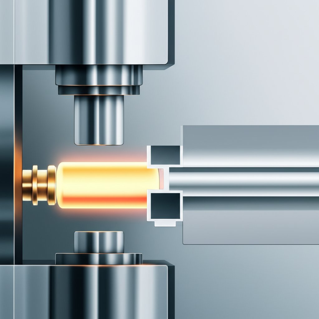
Când vă imaginați cum sunt fabricate formele personalizate din aluminiu, vă puteți întreba: cum devine o bucată simplă de metal semifabricat un profil precis pentru ferestre, electronice sau vehicule? Răspunsul se află în inima de extrudare din aluminiu —cel fieră extruziune . Pur și simplu, o matriță pentru extrudare din aluminiu este un disc solid din oțel care are o deschidere realizată cu grijă prin prelucrare mecanică, ce modelează aliajul de aluminiu încălzit atunci când este forțat să treacă prin aceasta sub o presiune enormă. Fiecare profil, indiferent dacă este o bară simplă sau un tub complex gol, începe cu o matriță adaptată secțiunii transversale a acestuia.
Definiție fragment recomandat: O matriță pentru extrudare din aluminiu este un instrument din oțel realizat cu precizie, care modelează aliajul de aluminiu într-un profil transversal specific în timpul procesului de extrudare.
Ce fac matrițele pentru extrudare din aluminiu în presă
Imaginați-vă un buci de aluminiu preîncălzit – gândiți-vă la el ca la un cilindru solid – încărcat într-o presă imensă. Pe măsură ce pistonul hidraulic avansează, bucile sunt strânse prin orificiul matriței. Designul matriței determină forma finală a profilului, calitatea suprafeței și chiar eficiența formării. Din acest motiv, înțelegerea ce este o matriță în industria de prelucrare este esențială pentru ingineri și proiectanți: matrița nu este doar o formă, ci este cea care controlează calitatea, costurile și durata de execuție în proiectele de extrudare. Matrița trebuie să reziste la forțe de până la 15.000 de tone, necesitând atât rezistență, cât și precizie. (Aceasta este limita superioară a capacității echipamentului, nu "forța" pe care o suportă direct matrița.)
Definiția matriței de extrudare și componentele esențiale
Hai să analizăm elementele de bază cu care vă veți confrunta atunci când lucrați cu matrițe de extrudare din aluminiu. Iată un mini-glosar pentru a vă începe:
- Atinge: Secțiunea matriței care controlează viteza de curgere și asigură precizia dimensională.
- Fața matriței: Suprafața matriței unde este tăiată forma profilului.
- Stivă de matrițe: Asamblarea matriței, a contrașablonului, a suportului și uneori a plăcii de alimentare – fiecare adăugând sprijin și aliniere.
- Contrașablon: Un disc gros de oțel situat în spatele matriței, care o întărește împotriva presiunii extreme.
- Placă de Alimentare: Uneori este utilizată pentru a ajuta la distribuirea fluxului de aluminiu și pentru a gestiona extrudarea continuă.
- Peretele Matriței: Grosimea oțelului care înconjoară deschiderea matriței, esențială pentru a rezista forțelor de presare.
Cum procesul de extrudare a aluminiului influențează deciziile de proiectare
The de extrudare din aluminiu nu este doar despre a forța metalul printr-o formă. Fiecare etapă – de la preîncălzirea lingoului până la tăierea finală – afectează realizarea și costul proiectului dumneavoastră. Iată un flux simplificat al procesului:
- Preîncălzire: Bulbii de aluminiu sunt încălziți pentru a obține o plasticitate optimă.
- Apăsați: Bulbiul este încărcat într-un container și împins de un tijă și piston prin pachetul de matrițe.
- Stingeţi! Profilul extrudat cald este răcit rapid pentru a-și fixa proprietățile.
- Tragere: Profilul este tras din patul presei pentru a menține dreptatea.
- Întindere: Distorțiunile minore sunt corectate prin întindere.
- Taie: Profilul este tăiat la lungimea dorită pentru prelucrare ulterioară sau livrare.
Proiectarea matriței este în strânsă legătură cu acești pași. De exemplu, suprafața de reazem în interiorul matriței este reglat pentru a echilibra fluxul, a minimiza distorsiunile și a obține o suprafață finisată corespunzător. Peretele matriței trebuie să fie suficient de gros pentru a rezista presiunii, în timp ce fața matriței determină geometria profilului. Alegerea făcută aici influențează nu doar toleranțele, ci și riscul de distorsiune și durata de viață a matriței însăși.
Există trei categorii principale de profile cu care veți întâmpina, fiecare necesitând o abordare diferită a matriței:
- Profile pline: Fără goluri interne — gândiți-vă la bare, unghiuri sau canale. Acestea folosesc matrițe mai simple și sunt în general mai economice.
- Profile semivide: Goluri parțial închise, cum ar fi un canal cu o deschidere îngustă. Acestea necesită matrițe mai complexe și o controlare atentă a fluxului.
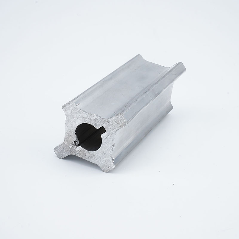
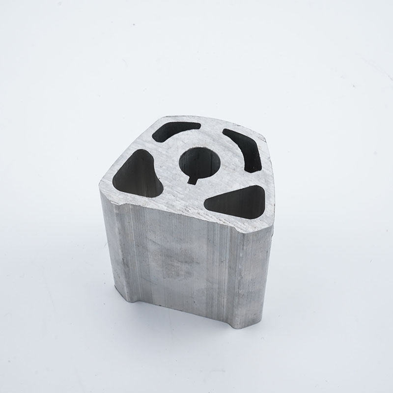
- Profile cu goluri: Goluri complet închise, cum ar fi țevile sau ramurile. Acestea necesită matrițe cu mandrin și o sculă de susținere complexă.
De exemplu, un unghi simplu în formă de L este un profil masiv, în timp ce un tub dreptunghiular este un profil gol. Fiecare tip aduce cu sine propriul set de compromisuri legate de proiectare și fabricație, pe care le vom explora în secțiunile următoare.
-
Deciziile privind matrița afectează:
- Toleranță și precizie dimensională
- Calitatea finisajului superficial
- Risc de deformare a profilului
- Durata de viață a matriței și intervalul de întreținere
Pe măsură ce înaintați, păstrați în minte aceste fundamentale. Alegerea pe care o faceți la etapa de proiectare a matriței va influența fiecare aspect al proiectului de extrudare — de la costuri la calitate și durata de viață a utilajelor. Sunteți gata să aprofundați? În continuare, vom analiza tipurile de matrițe și structura acestora și modul în care acestea influențează rezultatele.
Tipuri de matrițe și structura care determină rezultatele în extrudarea aluminiului
Matrițe Pline, Semi-goale și Goale
Când planificați o extrudare, unul dintre primele întrebări este: ce geometrie a profilului aveți nevoie? Răspunsul determină care tipuri de extrudare aluminiu matrițe sunt potrivite pentru proiectul dumneavoastră. Să detaliem:
| Tip die | Susține Geometria | Exemplu de Profil | Complexitate tipică | Necesități de control al fluxului | Sensibilitate la întreținere |
|---|---|---|---|---|---|
| Matrită Solidă | Total solid, fără goluri interne | Profil T, unghi L, bară plată | Scăzut | Reglare de bază a lungimii lagărului | Mai jos |
| Matriță Semi-goală | Sloturi parțial închise (nu complet închise) | Canal U cu slot îngust | Moderat | Necesită echilibrare atentă a fluxului | Mediu |
| Matriță tubulară (Matriță cu arbore de calibrare) | Voids complet închise | Țeavă, cutie, cavitate complexă | Înaltelor | Mandră, cameră de sudare, echilibrare precisă | Mai mare |
Matrițele solide sunt ideale pentru forme simple – gândește-te la un profil T simplu sau unghiular. Sunt cele mai economice matrită pentru extrudare din aluminiu variantă și mai ușor de întreținut. Matrițele semi-goale acoperă diferența, prelucrând profile cu fante aproape închise sau canale adânci, dar nu complet închise. Matrițele goale, deseori numite matrițe cu mandră , sunt concepute pentru țevi și profile cu spații interne complet goale. Aceste matrițe folosesc o mandră și bride pentru a crea spații interne complexe, fiind cele mai complicate tipuri de matrițe pentru extrudarea aluminiului.
Proiectarea matriței cu mandră și considerații privind camera de sudare
Matrițele goale se bazează pe o mandrina matriței și un sistem de poduri și camere de sudare. Mandrina formează interiorul profilului, în timp ce matrița înconjurătoare modelează exteriorul. Pe măsură ce aluminiul curge în jurul podurilor, acesta se divide și apoi se reunește în camera de sudare, formând custuri longitudinale. Calitatea acestor suduri este direct legată de modul în care metalul curge uniform în cameră – un flux neuniform poate duce la custuri slabe sau la defecte superficiale. De aceea, proiectarea precisă și simularea sunt atât de critice pentru acest matrița pentru extrudarea aluminiului de tip.
Pentru profile mai complexe – cum ar fi radiatoarele cu grosime variabilă a pereților – proiectanții pot utiliza plăci de alimentare avansate cu porturi sau plăci semianexe. În acest caz, simularea și ajustarea iterativă ajută la optimizarea fluxului, reducerea zonelor moarte și la îmbunătățirea integrității sudurilor [MDPI] .
Peretele Matriței, Lungimea de Rezemare și Echilibrarea Fluxului
Sună complicat? Poate fi, dar înțelegerea anatomiei ajută. peretele matriței asigură rezistență structurală, iar lungimea lagărului (porțiunea pe care o parcurge aluminiul de-a lungul matriței) este un factor esențial pentru echilibrarea fluxului. Lagărele mai lungi încetinesc metalul, ajutând la egalizarea vitezei de ieșire între secțiunile groase și cele subțiri; lagărele mai scurte îl accelerează. Combinarea corectă minimizează distorsiunile și fisurarea suprafeței.
Elemente de susținere – cum ar fi contrașinele, suporturile și plăcile de alimentare – oferă stabilitatea necesară fiecărui tip de matriță. Contrașinele întăresc matrița, suporturile distribuie forța, iar plăcile de alimentare ajută la ghidarea fluxului dificil în profilele semivide sau complexe solide. Fiecare componentă se integrează în pachetul matriței, lucrând împreună pentru a rezista presiunilor imense ale procesului de extrudare.
-
Listă de verificare: Alegerea între matrițe semivide și matrițe vide
- Este deschiderea aproape închisă, dar nu complet? Luați în considerare o matriță semividă.
- Are profilul nevoie de un spațiu complet închis? Optați pentru o matriță vidă cu un mandrin.
- Este rezistența cusăturii de sudare și calitatea suprafeței esențiale? Cereți informații despre echilibrarea fluxului și proiectarea camerei de sudare.
- Este profilul puternic asimetric sau variabil ca grosime a pereților? Așteptați o reglare mai complexă a fluxului și posibil simulare.
Reglarea fină a lungimii lagărelor este adesea cea mai rapidă metodă de a corecta dezechilibrele de flux descoperite în timpul primelor extrudări de probă.
Prin potrivirea corectă tipuri de extrudare aluminiu a matrițelor cu profilul dumneavoastră și prin înțelegerea modului în care interacționează pereții matriței, lagărele și echipamentele de susținere, veți crea premisele unei calități mai bune, a unei durate mai lungi de viață a matriței și a unor surprize mai puține în producție. În continuare, vom explora modul în care alegerea materialelor și a acoperirilor influențează în mod suplimentar durabilitatea matriței și compatibilitatea acesteia cu diferite aliaje de aluminiu.
Materiale pentru Matrițe, Acoperiri și Compatibilitatea cu Aliajele
Alegerea Oțelului pentru Matrițe în Vederea Durabilității și Controlului Termic
Când specificați o matrică de aliaj din aluminiu matriță, v-ați întrebat vreodată de ce unele durează mai mult sau performează mai bine pe anumite aliaje? Răspunsul începe cu oțelul pe care îl selectați. Pentru majoritatea sticle de extrudere aluminiu , H13 (cunoscut și sub numele de Orvar 2 Microdized) este calul de povară al industriei. De ce? Rezistența sa la șoc termic, rezistența la înmuierea termică și stabilitatea generală la temperaturile ridicate din procesul de prelucrare a matrițelor îl fac o alegere inteligentă implicită atât pentru aplicații simple, cât și pentru cele complexe.
Totuși, nu toate sarcinile sunt la fel. Dacă extrudezi profile mai complexe sau folosești aliaje cu rezistență mai mare, poți opta pentru oțeluri speciale pentru matrițe, cum ar fi QRO 90 Supreme sau Dievar. Acestea oferă o duritate și o tenacitate superioare la temperaturi ridicate, în special atunci când matrițele sunt expuse unor cicluri termice severe sau unor rapoarte mari ale limbii. Pentru componentele de susținere – cum ar fi plăcile de sprijin, inelele de matrițare sau mantalele – sortimentele precum Alvar 14 sau Impax Supreme asigură un echilibru între rezistență și prelucrabilitate, optimizând astfel atât performanța, cât și costul.
| Grad de oțel | Rezistență la oboseală termică | Rezistenta la uzura | Prelucrabilitate/Răspuns la prelucrare prin eroziune electrică (EDM) | Compatibilitate cu acoperirea | Note privind utilizarea tipică |
|---|---|---|---|---|---|
| H13 (Orvar 2 Microdized) | Înaltelor | Bun | Excelent | Foarte Bun | Standard pentru majoritatea matrițelor din aluminiu |
| H11 (Vidar 1) | Moderat | Bun | Excelent | Bun | Acolo unde este nevoie de o tenacitate suplimentară |
| QRO 90 Supreme | Foarte sus | Foarte Bun | Bun | Excelent | Pentru temperaturi extreme, rapoarte mari ale limbii |
| Dievar | Înaltelor | Înaltelor | Moderat | Bun | Rezistență ridicată, rezistență la fisurare |
| Unimax | Înaltelor | Înaltelor | Moderat | Bun | Pentru cea mai bună combinație de uzură/rezistență |
Alegerea oțelului potrivit se bazează pe mai mult decât doar costul inițial. Se bazează pe potrivirea aliajului, complexității profilului și a seriei de producție cu punctele forte unice ale oțelului. Dacă executați serii mari sau folosiți aliaje dificile, alegerea corectă utilajelor din aluminiu se poate amortiza prin reducerea timpilor de oprire și a intervalului mai lung între reparațiile matrițelor.
Când acoperirile adaugă valoare și când nu o fac
Ați observat vreodată cum unele matrițe par să reziste mai bine uzurii sau lipirii profilului decât altele? Aici intervin acoperirile și tratamentele superficiale. Nitrurarea este cea mai comună soluție de îmbunătățire utilaj din aluminiu . Creează un strat subțire și dur care mărește rezistența la uzură și reduce frecarea — ideal pentru combaterea straturilor de oxid abraziv din aliajele de aluminiu. Acoperirile PVD (depozitare fizică din fază de vapori) și tratamentele avansate de suprafață sunt, de asemenea, utilizate pentru a combate lipirea (adherența aluminiului la matriță) și reducerea rebutului inițial, deși eficiența lor economică depinde de scala producției și de geometria profilului.
| Acoperire/Tratament de suprafață | Avantaje | Dezavantaje | Impactul regrinderii | Cele mai bune cazuri de utilizare |
|---|---|---|---|---|
| Nitrurare | Mărește rezistența la uzură, reduce frecarea, eficient din punct de vedere al costurilor | Stratul poate fi erodat, necesită reaplicare | Regrinderea îndepărtează protecția, trebuie re-nitrurată | Standard pentru majoritatea fețelor de matrițe din aluminiu |
| Revopsire pvd | Rezistență superioară la lipire, finisaj neted | Cost mai ridicat, mai puțin utilizat pentru matrițe de volum mare | Strat subțire, ușor de pierdut dacă matrița este rectificată | Profile speciale, reducere deșeuri la pornire |
| Revestire dură | Rezistență extremă la uzură | Posibilă fragilitate, reparații complexe | Poate necesita renovare completă după uzură | Inele pentru zone critice, zone cu abraziune ridicată |
Iată un sfat: dacă matrița necesită rectificări frecvente, planificați tratamente superficiale repetate. Altfel, veți pierde beneficiile acoperirilor imediat ce restaurați forma matriței.
Asocierea materialelor de matrițare cu aliajele comune de aluminiu
Nu toate aliajele sunt compatibile cu fiecare material de matriță. Unele aliaje, în special cele cu siliciu sau magneziu ridicat, pot fi mai abrazive sau predispuse la lipire, influențând prelucrarea matriței și intervalele de întreținere. Iată un ghid prietenos pentru designeri privind combinarea corectă:
- serie 6xxx (arhitecturală, auto): H13 sau QRO 90 Supreme cu nitrurare; standard pentru majoritatea profilelor, oferă un echilibru bun între rezistența la uzură și tenacitate.
- serie 7xxx (structurală, aerospace): QRO 90 Supreme sau Dievar; este necesară o tenacitate și o rezistență la căldură mai mare, în special pentru funcționarea la presiune ridicată.
- serie 5xxx (marină, transport): H13/Orvar 2 Microdized; uzură moderată, dar fiți atenți la lipirea indusă de magneziu – tratamentele superficiale ajută.
- Aliaje cu conținut ridicat de siliciu: QRO 90 Supreme sau Unimax cu nitrurare sau îmbrăcăminte dură; necesare pentru o rezistență optimă la abraziune.
Unele aliaje, în special cele cu conținut scăzut de fier, cresc riscul lipirii aluminiului pe matriță. În aceste cazuri, pot fi necesare acoperiri avansate sau întreținere frecventă pentru a evita opririle și rebuturile.
-
Principalele concluzii privind selecția echipamentului din aluminiu:
- Potrivește oțelul matricei cu complexitatea profilului și familia de aliaje.
- Utilizează nitrurarea pentru majoritatea suprafețelor matricei din aluminiu; ia în considerare PVD sau aplicarea de straturi dure pentru sarcini dificile.
- Planifică reaplicarea periodică a tratamentelor superficiale după rectificare.
- Specifică în cererea ta de ofertă (RFQ) materialul și acoperirea preferate pentru matrice, dar rămâi deschis la expertiza furnizorului.
Prin înțelegerea acestor opțiuni de materiale și acoperiri, vei fi pregătit să prelungești durata de viață a matricei, să reduci întreținerea și să asiguri succesul primei piese produse – pregătind terenul pentru următoarea extrudare cu mai puține surprize și rezultate mai bune. În continuare, vom analiza cum aceste alegeri afectează metodele de fabricație ale matricei și ce înseamnă acest lucru pentru termenul de livrare și costurile proiectului tău.
Metode de fabricație ale matricei și compromisurile aferente
Frezarea CNC versus EDM cu fir și cu electrozi (Sinker EDM)
Când efectuați evaluarea fabricația matricei opțiuni, te-ai întrebat vreodată de ce unele matrițe sunt realizate prin frezare CNC, iar altele folosesc EDM (prelucrare prin descărcări electrice)? Răspunsul se află în punctele forte unice ale fiecărui proces și în modul în care acestea pot fi combinate pentru a obține atât viteză, cât și precizie pentru sticle de extrudere aluminiu .
Frezare CNC este principala metodă folosită în majoritatea proiectelor cu matrițe de extrudare. Aceasta este excelentă pentru degroșarea fețelor matriței, pentru formarea canalelor largi de curgere și pentru conturarea elementelor exterioare. Imaginează-ți o matriță cu curbe ample sau profile mari și deschise - frezele rotative ale unui utilaj CNC pot îndepărta materialul rapid și pot menține toleranțe strânse pe diferite tipuri de oțel. Totuși, atunci când vine vorba despre detalii fine - cum ar fi pereții subțiri, colțurile ascuțite sau buzunarele adânci și înguste - frezarea CNC își atinge limitele.
Aici este eDM cu fir și sinker EDM intervine. EDM cu fir utilizează un fir subțire, încărcat electric, pentru a tăia materialele conductive cu o precizie extremă, fiind ideal pentru decupări complexe, raze interne și caracteristici care ar fi imposibil sau nerentabil de realizat prin prelucrare mecanică convențională. Pe de altă parte, EDM cu scufundare folosește electrozi formați pentru a eroda cavitați complexe, cum ar fi camerele de sudură în matrițe goale. Ambele metode evită stresul mecanic, deci sunt perfecte pentru zone delicate sau cu precizie ridicată. În practică, majoritatea matrițelor de înaltă performanță folosesc o abordare hibridă — frezare CNC pentru îndepărtarea grosieră și EDM pentru caracteristicile finale, critice.
| Procesul | Cazuri tipice de utilizare | Caracteristici realizabile | Finalizare suprafață | Timp de așteptare | Factori de cost |
|---|---|---|---|---|---|
| Frezare CNC | Degroșare, profile deschise, canale largi | Raze mari, forme externe | Moderat (poate necesita lustruire ulterioară) | Mai rapid pentru forme simple | Uzură sculă, configurare, complexitate |
| EDM cu fir | Pereți subțiri, colțuri interne strânse, canale | Muchii ascuțite, secțiuni înguste/adânci | Fin (bavuri minime) | Mai lent pentru semifabricate groase sau mari | Consum de sârmă, număr de caracteristici |
| Sinker EDM | Cavitați complexe, camere de sudare, cavități adânci | Forme personalizate, goluri complexe | Fin (posibil să necesite lustruire) | Depinde de adâncimea și detaliile cavității | Fabricație electrozi, timp de ardere |
Inserții și răcire conformală realizate prin aditivare
În perspectivă, fabricația aditivă își face loc în matrițare —mai ales pentru inserturi sau canale de răcire pe care prelucrarea tradițională nu le poate realiza. Tehnologii precum topirea selectivă cu laser permit trasee interne de răcire conformale, îmbunătățind managementul termic și prelungind durata de viață a matriței. Deși nu sunt încă mainstream pentru fiecare proces matriță , caracteristici posibile prin aditiv sunt din ce în ce mai utilizate pentru aplicații extrem de solicitate sau cu volum mare de producție.
Alegerea unui procedeu de fabricație pentru proiectul tău de matriță
Cum alegi procedeul potrivit pentru profilul tău matrice pentru producție ? Începe prin identificarea caracteristicilor critice ale profilului—ai nevoie de raze interne strânse, canale adânci sau camere complexe de sudare interne? Dacă da, planifică un volum semnificativ de lucrări EDM. Pentru forme mai simple și deschise, frezarea CNC te va conduce mai repede și mai economic. Procedeele hibride sunt normă curentă, combinând ambele pentru a optimiza costul, precizia și timpul de execuție.
-
Indicații DFM care măresc timpul de prelucrare/EDM:
- Pereți sau nervuri foarte subțiri
- Canale sau buzunare adânci și înguste
- Schimbări bruște ale secțiunii transversale
- Colțuri interne ascuțite (evitați atunci când este posibil)
- Subtaleri extinse sau draft negativ
Și finisajul suprafeței este important. EDM oferă de obicei un finisaj mai fin (mai puține muchii, postprocesare minimă) comparativ cu frezarea, însă ambele metode pot necesita lustruire manuală sau șlefuire pentru suprafețele critice, mai ales acolo unde toleranțele la prelucrarea prin extrudare sunt strânse. Pentru referință, rugozitatea suprafeței după lustruirea finală la matrițele de extrudare poate atinge Ra 0,03–0,04 µm pentru aplicații standard, sau chiar mai fin pentru matrițe de calitate optică.
Alegerea traseului optime de fabricație din faza incipientă — prin potrivirea caracteristicilor matriței cu punctele forte ale prelucrării mecanice — minimizează redizajele costisitoare și asigură că proiectul dvs. de prelucrare prin extrudare se desfășoară conform programului.
Pe măsură ce finalizați proiectul matriței, țineți cont de aceste compromisuri. Următoarea secțiune vă va ghida printr-o listă practică de verificare DFM, ajutându-vă să evitați capcanele comune și să asigurați succesul proiectului dvs. de extrudare.
Listă practică de verificare DFM pentru profilele de extrudare
Ai desenat vreodată un profil din aluminiu care părea perfect pe hârtie, doar pentru a descoperi ulterior că se răsucește, se deformează sau uzează sculele mai repede decât te așteptai? Aici intervine un checklist DFM (Design for Manufacturability) solid, prietenos pentru proiectanți. Cel mai bun ghid de proiectare pentru extrudare aluminiu nu este doar o listă cu lucruri permise și interzise; este un set de strategii verificate care te ajută să eviți cele mai frecvente greșeli înainte ca proiectul tău să ajungă măcar în atelierul de fabricație a matrițelor.
Recomandări privind grosimea pereților și lungimea de reazem
Atunci când stabilești grosimea pereților, există tentația de a merge cât mai subțire pentru a economisi greutate. Dar știai că neuniformitatea grosimii pereților este una dintre principalele cauze ale dezechilibrului de curgere și deformării în proiectarea matrițelor de extrudare? Iată cum să faci lucrurile corect:
- Încurajează o grosime uniformă a pereților. Menține variația de grosime într-un raport de maximum 2:1 în întregul profil. Diferențele mari determină metalul să curgă cu viteze diferite, provocând defecte la suprafață și stres în matriță.
- Folosește tranziții treptate. Acolo unde grosimea trebuie să se modifice, combinați-o cu raze generoase (racordări interne ≥ 0,5–1,0 mm reprezintă un punct solid de plecare pentru majoritatea aliajelor).
- Verificați grosimea minimă realizabilă împreună cu furnizorul dumneavoastră. Pentru aliaje din seria 6xxx, grosimea tipică este de 1,2–1,6 mm, însă verificați întotdeauna pe baza diametrului cercului circumscris (CCD) și a lățimii caracteristicilor.
- Ajustați lungimea lagărelor pentru controlul fluxului. Lagărele mai lungi încetinesc metalul; cele mai scurte îl accelerează. Utilizați acest principiu pentru a echilibra vitezele de ieșire și a minimiza distorsiunile.
Reguli privind razele de colț, simetria și centrarea
Colțurile ascuțite și profilele asimetrice pot părea atragătoare pe ecran, însă creează dificultăți atât pentru matrițele de extrudare, cât și pentru produsul final. Aveți în vedere următoarele reguli din fiecare ghid de proiectare fiabil pentru extrudarea din aluminiu:
- Rotunjiți toate colțurile interne și externe. Aceasta reduce stresul asupra matriței, minimizează riscul de rupere a limbii matriței și îmbunătățește calitatea suprafeței. Evitați muchiile ascuțite și marginile foarte subțiri.
- Proiectați cu simetrie ori de câte ori este posibil. Profilele simetrice distribuie fluxul de metal și încărcătura pe matriță în mod egal, reducând răsucirea și curbarea. Dacă este necesară o asimetrie, folosiți caracteristici simetrice sau adăugați buzunare pentru echilibrarea fluxului.
- Centrați masa și caracteristicile de-a lungul unei axe logice. Aceasta ajută la menținerea rectitudinii și simplifică asamblarea ulterioară.
Gestionarea nervurilor, deschiderilor și echilibrului fluxului
Nervurile, șinele și deschiderile pot adăuga rezistență și funcționalitate, dar dacă sunt gestionate greșit, pot cauza reparații frecvente sau avarii ale matriței. Iată cum puteți menține matrița și echipamentul robuste:
- Preferați nervuri subțiri și frecvente în loc de pereți groși unici. Nervurile subțiri și apropiate îmbunătățesc rigiditatea și planitatea, controlând viteza de curgere.
- Verificați raportul de aspect al nervurilor și nervurilor de rigidizare. Pentru aripioare de radiator sau nervuri înalte, mențineți raportul înălțime/gol ≤ 4:1. Caracteristicile înalte și subțiri tind să se onduleze și pot duce la ruperea matriței.
- Evitați nervurile lungi, neasigurate și deschiderile adânci și înguste. Acestea cresc uzura matriței și riscul de deformare. Dacă o fantă îngustă este esențială, luați în considerare un tab de fixare temporar pentru a o stabiliza în timpul extrudării, eliminându-l ulterior printr-o tăietură ușoară.
- Planificați caracteristici de relief și racordări ample. Acestea reduc marcare matriței și facilitează curgerea mai uniformă a metalului la început, îmbunătățind atât durata de viață a matriței, cât și calitatea profilului.
Greșeli frecvente de evitat în proiectarea matrițelor de extrudare
- Combinarea pereților groși cu pereți subțiri fără ajustarea lungimii lagărelor pentru o curgere echilibrată.
- Specificarea unor cavități adânci și închise ca fiind semi-goale în loc de complet goale – aceasta poate suprasolicita matrița și poate duce la ruperea acesteia.
- Neglijarea necesității razelor interne la îmbinături, ceea ce poate duce la dungi pe suprafață sau la cedarea matriței.
- Complicarea inutilă a profilului cu elemente care nu au funcționalitate și care încetinesc procesul de extrudare și cresc cantitatea de deșeuri.
Simetria și traseele de alimentare echilibrate la început sunt cea mai bună garanție împotriva deșeurilor costisitoare și a refacerii matriței – dacă acestea sunt corect realizate, rezultatele obținute la prima probă se îmbunătățesc semnificativ.
Imaginați-vă că revizuiați proiectul matricei de extrudare cu acest checklist în mână. Vei observa mai puține modificări în fazele finale, mai puțină corespondență cu echipa matricei și a utilajelor, și o producție mai previzibilă și cu randament ridicat. Pentru o analiză mai aprofundată, consultați un ghid de proiectare de încredere pentru extrudarea aluminiului sau contactați furnizorul în timp util – aceștia pot identifica caracteristici riscante și vă pot ajuta să optimizați atât performanța, cât și capacitatea de fabricație Sfaturi pentru Proiectare AEC ).
Gata să te asiguri că profilele îndeplinesc atât cerințele funcționale, cât și cele privind fabricația? Următorul pas este să stabilești așteptări realiste privind toleranțele și finisajul suprafeței – esențiale pentru alinierea desenelor tehnice, a planurilor de inspecție și a strategiilor de finisare.
Toleranțe, Finisaj Suprafață și Planificarea Inspecției pentru Matrițele de Extrudare Aluminiu
Vă întrebați vreodată de ce două profile de la furnizori diferiți – chiar și cu același desen – pot părea atât de diferite în ceea ce privește potrivirea și finisajul? Acesta este universul toleranțelor și al calității suprafeței în matrițele pentru profiluri din aluminiu extrudat. Hai să analizăm ce influențează cu adevărat precizia dimensională, cum este gestionat finisajul suprafeței și cum menține o inspecție riguroasă proiectul dumneavoastră pe drumul cel bun.
Ce determină toleranțele la extrudare?
Sună complicat? Poate fi, dar înțelegerea factorilor principali vă ajută să stabiliți așteptări realiste. Toleranțele dimensionale în matrică de extrudere din aluminiu lucrare nu depind doar de geometria matriței – ele sunt rezultatul unui lanț de influențe:
- Complexitatea profilului: Formele simple și simetrice sunt mai ușor de realizat cu toleranțe strânse. Designurile complexe sau puternic asimetrice sunt mai predispuse la deformări.
- Construcția și proiectarea matriței: Lagărele mai lungi și echilibrate ajută la controlarea fluxului de metal și a vitezei de ieșire, influențând direct consistența profilului.
- Stabilitatea presei: Variațiile presiunii, temperaturii sau vitezei pot determina schimbări subtile ale dimensiunilor de la un ciclu la altul.
- Strategia de călire și răcire: Viteza și uniformitatea cu care este răcit profilul extrudat afectează atât dimensiunile, cât și rectitudinea.
- Manipularea post-extrudare: Întinderea, tăierea și stivuirea pot introduce sau corecta modificări minore ale dimensiunilor.
Standardele industriale – cum ar fi cele publicate de The Aluminum Association – oferă o referință pentru ceea ce este realizabil în mod obișnuit, însă multe matrițe de extrudare din aluminiu pot fi ajustate pentru rezultate și mai precise, atunci când aplicația o cere. Cu toate acestea, toleranțele mai strânse înseamnă de obicei costuri mai mari și timpi de livrare mai lungi, astfel că este important să specificați doar ceea ce proiectul dumneavoastră are cu adevărat nevoie ( Toleranțe AEC ).
Ținte privind finisajul superficial în funcție de clasa profilului
Atunci când vă imaginați un profil finalizat, vă gândiți la un aspect periat, anodizat sau cu vopsea în pulbere – sau ceva mai industrial? Finisajul superficial este modelat atât de matrice, cât și de procesul ulterior de finisare. Iată cum interacționează acestea:
- Starea și designul matriței: Suprafețele bine lustruite ale matriței și lungimea corespunzătoare a lagărelor contribuie la minimizarea liniilor și dârelor de extrudare.
- Alegerea aliajului: Unele aliaje se extrudează cu un finisaj natural mai neted decât altele; aliajele cu conținut ridicat de siliciu sau magneziu pot fi mai dificile de prelucrat.
- Condițiile de producție: Parametrii stabili de extrudare și semifabricatele curate duc la mai puține defecte de suprafață.
- Opțiuni de finisare: Perierea, anodizarea și vopsirea în pulbere pot acoperi imperfecțiunile minore sau le pot evidenția, în funcție de proces și culoare.
Profilele arhitecturale (gândiți-vă la ramurile de ferestre) necesită adesea cea mai înaltă calitate a suprafeței, în timp ce piesele pentru radiatoare sau industriale pot tolera mai multe linii vizibile de extrudare. Iată o comparație rapidă pentru a stabili așteptările:
| Clasa profilului | Strânsă (cea mai strânsă realizabilă) | Finisaj superficial acceptabil | Caracteristici esențiale de inspecție |
|---|---|---|---|
| Industrie construcțională | Strânsă (cea mai strânsă realizabilă) | Neted, linii minime; adesea anodizat sau vopsit electrostatic | Planeitate, răsucire, grosimea pereților, imperfecțiuni de suprafață |
| Radiatoare/Termic | Moderat (oarecare flexibilitate) | Linii de extrudare vizibile sunt acceptabile; accent pe dreptitudinea nervurilor | Înălțimea aletelor, distanța dintre nervuri, dreptitudinea generală |
| Structural/Industrial | Standard (normă industrială) | Finisaj funcţional; se permit mici urme | Poziţia găurilor, grosimea inimii, dimensiunile generale |
Amintiţi-vă, finisajele as-extruded arată mereu anumite linii sau zone legate de proces. Procesul corect de finisare poate îmbunătăţi aspectul, dar este recomandat să vă aliniaţi aşteptările privind suprafaţa cu utilizarea finală a profilului ( Manual Hydro ).
Puncte de inspecţie şi configurarea metrologiei
Cum vă asiguraţi că utilajele de extrudare livrează ceea ce aţi specificat? Aici intervine o inspecţie temeinică. Asigurarea calităţii nu presupune doar un control final – este un şir de paşi de la lingou la produsul ambalat:
- Suprafețe de referință critice: Planeitatea și paralelismul suprafețelor principale de montare sau îmbinare
- Relația dintre gaură și canal: Poziția și dimensiunea tuturor decupajelor funcționale
- Zone cu pereți subțiri: Consistența și grosimea minimă, în special la profile complexe
- Verificări de simetrie: Asigurarea corespondenței profilului cu liniile și axele centrale intenționate
- Răsucire și curbură: Rectitudinea generală, în special pentru profile lungi sau subțiri
Instrumente tipice includ sublerul, micrometre, scanere laser și profilometre pentru rugozitatea suprafeței. Pentru producții în volum mare, sistemele de inspecție automată și planurile detaliate de inspecție contribuie la identificarea timpurie a problemelor și prevenirea reprelucrărilor costisitoare ulterioare.
Alinierea desenelor, planului de inspecție și a așteptărilor privind finisarea cu ale furnizorului de matrițe este cheia pentru reducerea neînțelegerilor și a reprelucrărilor. Înțelegând modul în care toleranțele și finisajul suprafeței sunt influențate la fiecare etapă—de la proiectarea matriței, la operațiunea de presare și până la inspecția finală—veți asigura programului dumneavoastră lansări mai fluide și rezultate mai previzibile.
Doriți să mențineți aceste standarde înalte pe termen lung? În continuare, vom explora strategii de întreținere și recondiționare pentru a prelungi durata de viață a matrițelor și a păstra calitatea producției.
Ghid de întreținere și recondiționare a matrițelor
Intervale de inspecție și indicatori de uzură
Când investeşti într-o aluminium die pentru extrudare, cum vă asigurați că oferă o calitate constantă – la fiecare utilizare? Răspunsul este o rutină proactivă de întreținere, începând cu inspecții regulate. Dar când ar trebui să verificați matricea și care sunt semnele evidente că are nevoie de atenție?
- După primele rulări: Identificați problemele timpurii de curgere, uzura lagărelor sau problemele de aliniere înainte de a crește producția.
- Rulări timpurii de producție: Verificați defectele de suprafață, microfisurile sau modelele neobișnuite de uzură pe măsură ce matricea se stabilizează.
- Verificări periodice (după volum sau ore): Stabiliți un program în funcție de producție – matricele cu volum mare pot necesita verificări săptămânale, în timp ce sarcinile cu volum redus pot fi lunare.
În timpul fiecărei inspecții, căutați acești indicatori comuni ai uzurii:
- Uzura lagărelor: Eroziunea sau rotunjirea planului de reazem al lagărului poate duce la pierderea preciziei profilului.
- Microfisurare: Fisuri minuscule, în special în zonele cu solicitare ridicată, indică oboseala materialului și posibilitatea de cedare.
- Pregătire/Lipire: Aluminiul se lipește de suprafața matriței, adesea cauzat de lubrifiere necorespunzătoare sau aliaje dificile.
- Eroziune în camerele de sudură: În special la matrițele goale, eroziunea poate slăbi cusăturile de sudură și poate afecta rezistența profilelor.
- Defecte de suprafață: Scrânteturi, dungi sau depuneri pe fața matriței pot fi transmise direct asupra imperfecțiunilor profilelor.
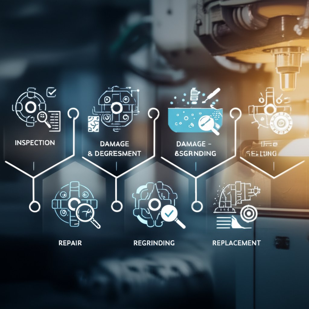
Opțiuni de recondiționare: Sudare, Rectificare, Refacerea stratului de placare
Nu fiecare problemă înseamnă că este momentul să înlocuiți matrița. Multe probleme pot fi rezolvate prin recondiționare, prelungind durata de viață a matriței matrita de extrudare si economisirea costurilor de inlocuire. Iata o analiza a optiunilor comune de reparatii, impreuna cu avantajele si dezavantajele lor:
-
SUDURA: Umple craterele sau reface zonele uzate.
Pro: Restabileste geometria, fiind o solutie cost-eficienta pentru daune localizate.
Dezavantaje: Poate introduce tensiuni reziduale; necesita o reparatie realizata de un specialist pentru a evita aparitia unor noi puncte slabe. -
Rectificare/Polizare: Indeparteaza uzura de suprafata, restaureaza suprafata portanta.
Pro: Mbunatateste finisajul suprafetei si precizia profilului.
Dezavantaje: Reduce lungimea suprafetei portante, ceea ce poate influenta echilibrul fluxului; poate necesita re-nitrurare sau re-coatere. -
Refacerea placarii/Tratament superficial: Aplică un strat protector proaspăt (de exemplu, nitrurare).
Pro: Crește rezistența la uzură, reduce aderarea.
Dezavantaje: Trebuie reaplicat după fiecare rectificare; nu este o soluție pentru daune profunde.
Fiecare reparație trebuie înregistrată în registrul atelierului de matrițe – urmărindu-se ce a fost făcut, când și de ce. Această documentație ajută la identificarea problemelor recurente și la planificarea întreținerii viitoare.
Când să retrageți o matriță și să comandați una nouă
Uneori, cea mai bună decizie este să retrageți o matriță și să investiți într-o înlocuitoare. Dar cum știți când ați ajuns la acest punct? Folosiți acest flux simplu de decizie:
- Verificați matrița pentru uzură, crăpături sau deformări.
- Dacă daunele sunt minore și localizate, luați în considerare reparația (sudare, rectificare sau reacoperire).
- Dacă reparațiile au fost frecvente sau lungimea portantă este acum sub specificația minimă, evaluați calitatea profilului după recondiționare.
- Dacă toleranțele profilului sau calitatea suprafeței nu mai pot fi menținute – chiar și după mai multe reparații – este momentul să retrageți matrița.
- Comandați un ștanț nou și utilizați înregistrările privind întreținerea pentru a informa modificările de proiectare sau actualizările de materiale.
-
Modele frecvente de uzură și cauzele probabile:
- Rotunjirea marginilor: Presiune excesivă sau lubrifiere insuficientă.
- Fisurare: Oboseală termică sau aliniere incorectă în stiva de ștanțe.
- Aderare/lipire: Probleme legate de alegerea aliajului sau de tratamentul superficial.
- Eroziunea camerei de sudare: Curgere cu viteză mare sau incluziuni abrazive.
-
Opțiuni de reparație în format sintetic:
- Sudare: Cea mai potrivită pentru fisuri sau zone ciobite.
- Rectificare/lustruire: Pentru restaurarea finisajului superficial și uzura minoră.
- Refinere/satinare: Pentru a restaura rezistența la uzură după rectificare.
- Înlocuire: Atunci când reparațiile nu mai pot restabili funcționalitatea sau calitatea.
Documentarea ajustărilor fluxului și a reparațiilor matriței scurtează schimbările viitoare și ajută echipa să identifice și rezolve mai eficient problemele recurente.
Imaginați-vă că echipa dvs. are un plan clar de întreținere și un jurnal de reparații bine organizat. Vei observa mai puține opriri nesolicitate, o mai bună consistență a profilului și o relație mai fluidă cu partenerii din industria matrițelor. Această abordare structurată nu vizează doar menținerea funcționării actualelor matrițe – ci și planificarea opririlor, bugetizarea pieselor de schimb și menținerea calității pentru fiecare producție. Pe măsură ce priviți în viitor, înțelegerea acestor strategii de întreținere vă va ajuta să luați decizii mai inteligente privind aprovizionarea și costurile, pe care le vom aborda în următoarea secțiune.
Factori de Cost, Strategie de Aprovizionare și Selecția Partenerilor pentru Matrițele de Extrudare a Aluminiului
Ce determină costul și termenul de livrare al matriței?
V-ați întrebat vreodată de ce doi furnizori pot oferi prețuri sau termene de livrare atât de diferite pentru același profil de extrudare? Răspunsul se află în modul în care fiecare fabrică de extrudare a aluminiului abordează principalii factori de cost. Hai să analizăm ce influențează cu adevărat costul final și termenul de livrare atunci când achiziționați sticle de extrudere aluminiu :
- Complexitatea profilului: Formele simple (cum ar fi barele plate) sunt mai ieftine, în timp ce designurile complexe cu mai multe goluri, pereți subțiri sau toleranțe strânse necesită mașinare avansată și puncte de inspecție mai riguroase.
- Profil solid vs. cavitar vs. semi-cavitar: Matrițele cavitare sau cu mai multe camere necesită mandrine, poduri și o echilibrare atentă a fluxului – ceea ce înseamnă mai multe componente și o precizie mai mare, crescând atât costul, cât și termenul de livrare.
- Reglarea lungimii portante: Fiecare ajustare a lungimii portante (pentru echilibrarea fluxului) adaugă timp de proiectare, simulare și testare.
- Oțelul pentru matrițe și acoperirile acestora: Trecerea de la oțelul standard H13 la oțeluri premium sau adăugarea de tratamente superficiale precum nitruriarea/PVD poate crește costul de bază cu 15–30%, dar poate prelungi durata de viață a matriței.
- Caracteristici intensive EDM: Canale adânci, colțuri ascuțite sau suprafețe cu mai multe niveluri necesită o prelucrare extensivă prin EDM (Electrical Discharge Machining), care este mai lentă și mai costisitoare decât frezarea CNC de bază.
- Cicluri de validare și omologare: Fiecare revizuire sau întârziere în aprobarea desenelor poate prelungi termenul de execuție, mai ales pentru aplicații auto sau reglementate.
Timpul de execuție pentru matrițe la comandă variază în mod obișnuit între 7 și 20 de zile, în funcție de complexitate și de capacitatea fabricii de profile extrudate din aluminiu. Proiectele complexe sau cu volum mare pot necesita matrițe cu mai multe cavitați, care costă mai mult inițial, dar reduc prețul unitar pentru serii mari.
Alegerea unui partener de producție pentru matrițe și piese
Alegerea partenerului potrivit nu se bazează doar pe preț. Imaginați-vă că lansați un nou program auto: aveți nevoie de un furnizor care să poată gestiona proiectarea matrițelor, producția și operațiunile aval – toate în timp ce respectă standardele stricte de calitate. Iată cum se compară principalii producători de matrițe și partenerii pentru extrudare:
| Furnizor | Aria de competență | Pregătire pentru industria auto | Asistență la întreținerea matriței | Servicii cu valoare adăugată | Model de angajament |
|---|---|---|---|---|---|
| Furnizorul Shaoyi Metal Parts | Extrudare auto și fabricare de matrițe complet integrate | IATF 16949, PPAP, prototipare rapidă | Proiectare integrată a matriței, întreținere și DFM | Prelucrare, finisare, asamblare, documentație QA | Soluție completă, la cheie |
| Magazin specializat de matrițe | Construcție personalizată de matrițe, profile experimentale | Poate varia; verificați certificatele | Reparații, recondiționare sau rectificare la cerere | Doar matrițe, cu prelucrare aval limitată | Pe proiect, la alegere |
| Fabrică mare de extrudare din aluminiu | Profiluri standard, volum mare | Standarde ISO/TS, capabil pentru industria auto | Întreținere rutinară a matrițelor, suport pe loturi | Extrudare în vrac, prelucrare mecanică de bază | Contractual, bazat pe volum |
Pentru programe auto și cu o complexitate ridicată, parteneri integrați precum Shaoyi oferă avantajul unui singur punct de responsabilitate pentru calitatea matriței și a piesei finite. Suportul lor tehnic poate contribui la optimizarea DFM, reducerea riscului de modificări costisitoare ale matrițelor și eficientizarea întregului ciclu de dezvoltare. Pentru profile experimentale sau foarte exotice, un atelier specializat de matrițe poate fi mai potrivit, mai ales dacă aveți nevoie de iterații rapide sau de tipuri unice de matrițe .
Echilibrarea complexității, a acoperirilor și a volumului de producție
Vă întrebați cum să structurați cererea dvs. de ofertă sau cum să justificați investiția în matrițe? Iată o listă practică cu zone de impact asupra costurilor pe care să le discutați cu furnizorul dumneavoastră:
- Geometria profilului (numărul de goluri, grosimea pereților, CCD)
- Tipul matriței (solidă, semi-golită, golită, multi-cavitate)
- Cerințele privind proiectarea canalelor de curgere și simularea fluxului
- Alegerea oțelului pentru matriță și orice tipuri de acoperiri (nitrurare, PVD etc.)
- Timpul de prelucrare EDM vs. CNC pentru caracteristici critice
- Durata de viață a matriței vs. volumul producției (logica amortizării)
- Comenzi de serie pentru mai multe matrițe (potențiale reduceri)
- Asistență pentru întreținere și recondiționare
Amortizarea costului matriței pe volumul proiectat de producție este esențială – ceea ce pare scump la început poate deveni neglijabil pe piesă în cazul producțiilor în volum mare. De exemplu, o matriță de 2.000 USD cu o durată de viață de 40.000 kg rezultă în doar 0,05 USD pe kg. Discutarea acestor puncte logice cu partenerul dumneavoastră ajută la evitarea surprizelor și asigură faptul că investiția în fabricația matrițelor se aliniază cu obiectivele reale de cost.
Furnizorii integrați vă pot ajuta să optimizați atât costul matriței, cât și al pieselor, combinând expertiză DFM, validare automotive și gestionare eficientă a lanțului de aprovizionare – deosebit de valoroasă pentru industriile dinamice.
Pe măsură ce pregătiți următorul dvs. RFQ, utilizați aceste categorii de costuri pentru a ghida discuțiile și evaluați dacă este mai bine să colaborați cu un partener single-source sau cu un atelier specializat de matrițe. În continuare, vom rezuma pașii concreți pentru specificațiile și RFQ-urile dvs., astfel încât să puteți trece de la planificare la producție cu încredere.
Pași următori pentru specificații și RFQ-uri
Ce să includeți în RFQ-ul dvs. pentru matrițe și profile
Când sunteți gata să treceți de la proiectare la producție, cum vă asigurați că furnizorul înțelege cu adevărat nevoile dvs.? Răspunsul se află într-un RFQ (Request for Quote) bine pregătit, care acoperă fiecare detaliu esențial. Conform celor mai bune practici din industrie, un RFQ complet nu doar că accelerează procesul de ofertare, ci pregătește și terenul pentru o lansare mai ușoară a proiectului și pentru mai puține probleme tehnice ulterior.
- Scopul și clasa profilului: Descrieți utilizarea finală, fie că este structurală, arhitecturală sau termică. Este un profil masiv, semivoid sau cu goluri?
- Finisaj așteptat: Indicați dacă aveți nevoie de anodizare, vopsire în pulbere, periere sau suprafețe extrudate.
- Familia aliajului și tratamentul termic: Specificați aliajul (de exemplu, 6061, 6063 sau seria 7000) și tratamentul termic necesar pentru performanță.
- Volume estimate: Indicați estimarea anuală a utilizării și dimensiunile loturilor.
- Priorități privind toleranțele: Evidențiați dimensiunile critice, zonele care necesită un control strict și cele unde toleranțele standard sunt acceptabile.
- Opțiuni de acoperire admise pentru matrițe: Mentionați dacă aveți nevoie de nitrurare, PVD sau alte tratamente superficiale pentru a prelungi durata de viață a matriței.
- Abordarea estimată privind întreținerea: Întrebați despre opțiunile de recondiționare și durata tipică de viață a matriței pentru clasa dvs. de profil
- Note privind planul de inspecție: Solicitați evaluarea unui eșantion, rapoartele privind primul articol și punctele cheie de inspecție pentru producție
Referirea la ghidurile de proiectare pentru extrudarea aluminiului atunci când pregătiți cererea dvs. de ofertă vă asigură că abordați restricțiile comune legate de fabricabilitate, cum ar fi grosimea minimă a pereților sau forma unei matrițe, și vă ajută să evitați redimensionările costisitoare ulterior [Ghiduri de proiectare AEC] .
Coordonarea proiectării, asigurării calității și producției
Sună complicat? Nu trebuie să fie. Comunicarea timpurie și clară între echipele de proiectare, calitate și producție este cea mai bună garanție împotriva interpretărilor greșite și a problemelor ulterioare. Partajați fișiere CAD, tabele de toleranțe și așteptările privind finisajul suprafeței de la început. Dacă este posibil, organizați o revizuire a proiectului orientată spre fabricație (DFM) cu furnizorul dumneavoastră pentru a discuta orice caracteristici care ar putea pune probleme privind grosimea pereților matriței, lungimea cuzinetului sau, în general, extrudabilitatea. Această abordare colaborativă – descrisă în majoritatea ghidelor de proiectare pentru extrudarea aluminiului – poate reduce numărul de iterații ale cererii de ofertă (RFQ) și poate accelera procesul până la obținerea primului articol validat.
Înainte de producția de serie, solicitați profile de probă sau un test pilot pentru a verifica eventualele distorsiuni, calitatea finisajului și precizia dimensională. Analizarea acestor probe împreună cu echipa dumneavoastră asigură faptul că matrițele pentru extrudare și produsul final îndeplinesc atât cerințele funcționale, cât și pe cele vizuale. Nu uitați să documentați orice reglaje convenite privind matrița sau procesul, pentru referință ulterioară.
Resurse Recomandate și Contactarea Partenerilor
Căutați un partener verificat care să vă sprijine de la proiectarea matriței până la piesele finite? Pentru programe auto și programe complexe, luați în considerare contactarea companiei Furnizorul Shaoyi Metal Parts . Abordarea lor integrată acoperă ingineria expertă a matrițelor, analiza DFM și operațiunile complexe downstream - ajutându-vă să aliniați fiecare fază a proiectului cu cele mai bune practici, de la început. Pentru alte aplicații, explorați furnizorii verificați care urmează recomandările recunoscute privind proiectarea profilelor de aluminiu și oferă oferte transparente, control de calitate riguros și asistență post-vânzare operativă.
"Un RFQ detaliat și alinierea timpurie DFM reduc semnificativ riscul proiectului, minimizează schimbul costisitor de informații și stabilește fundamentul pentru un program de extrudare de succes."
- Colectați toate desenele tehnice și specificațiile, inclusiv grosimea pereților, toleranțele și forma matriței.
- Consultați recomandările privind proiectarea profilelor de aluminiu pentru a valida capacitatea de fabricație.
- Definiți clar cerințele privind calitatea și finisajul în RFQ.
- Implicați furnizorul în timp util pentru a obține feedback privind DFM și pentru evaluarea probelor.
- Documentați toate modificările convenite și punctele de inspecție pentru rundele viitoare.
Sunteți gata să faceți următorul pas? Începeți prin a revizui schița cererii dvs. de ofertă (RFQ) în conformitate cu lista de verificare de mai sus și revedeți secțiunile anterioare ale acestui ghid pentru analize detaliate privind materialele, fabricarea matrițelor și strategiile de întreținere. O abordare atentă și bine structurată, fundamentată pe ghidurile din industrie, vă asigură rezultate fiabile și economice la extrudarea aluminiului, indiferent cât de complexe sunt cerințele dvs.
Întrebări frecvente despre matrițele pentru extrudarea aluminiului
1. Ce este o matriță pentru extrudarea aluminiului și cum funcționează?
Un ștanț pentru extrudare din aluminiu este un instrument precis din oțel care are o deschidere modelată, care transformă aliajul de aluminiu încălzit într-un profil cu o anumită secțiune transversală, atunci când este forțat să treacă prin aceasta sub presiune ridicată. Designul ștanței determină forma finală, calitatea suprafeței și precizia dimensională a piesei extrudate, făcându-l un component esențial în procesul de extrudare a aluminiului.
2. Care sunt principalele tipuri de ștanțe pentru extrudarea aluminiului?
Există trei tipuri principale de ștanțe pentru extrudarea aluminiului: ștanțe solide pentru profile fără goluri interne, ștanțe semigolite pentru forme cu canale aproape închise și ștanțe golite (cu matriță) pentru profile complet închise, cum ar fi țevile. Fiecare tip susține diferite geometrii și niveluri de complexitate, influențând costul, întreținerea și eficiența producției.
3. Cum influențează materialul și acoperirile ștanței durata de viață și performanța acesteia?
Materialul matriței, cum ar fi oțelul special H13, oferă rezistența și rezistența termică necesare pentru cicluri repetate de extrudare. Tratamentele de suprafață, cum ar fi nitrurarea sau acoperirile PVD, îmbunătățesc rezistența la uzură și reduc aderența, prelungind durata de viață a matriței și îmbunătățind calitatea profilului. Alegerea combinației potrivite, în funcție de compatibilitatea aliajului și volumul de producție, este esențială pentru durabilitate și rezultate consistente.
4. Ce factori influențează costul și timpul de execuție pentru matrițele de extrudare a aluminiului?
Complexitatea profilului, tipul matriței (solidă, semividă, vidă), toleranțele necesare, alegerea oțelului și a acoperirilor pentru matriță, precum și procesul de fabricație (frezare CNC, EDM) influențează toate costul și timpul de execuție. Colaborarea cu un furnizor integrat precum Shaoyi facilitează proiectarea, producția și validarea matriței, contribuind la reducerea întârzierilor și la optimizarea costurilor pentru proiecte auto și cu volum mare de producție.
5. Ce ar trebui să includă un RFQ pentru matrițe de extrudare a aluminiului?
Un RFQ complet ar trebui să specifice scopul și clasa pentru care este destinat profilul, cerințele privind finisajul, aliajul și tratamentul termic, volumele estimate, toleranțele principale, acoperirile preferate pentru matrițe, abordarea estimată privind întreținerea și criteriile de inspecție. O colaborare timpurie privind DFM cu furnizorul dumneavoastră, cum ar fi Shaoyi, asigură realizabilitatea produsului și alinierea proiectului matriței la nevoile proiectului dumneavoastră.