 Maži serijos dydžiai, aukšti standartai. Mūsų greito prototipavimo paslauga leidžia patvirtinti rezultatus greičiau ir lengviau —

Štampavimo šablonas iššifruotas: nuo žaliavos plieno iki tiksliai pagamintų detalių
Kas yra štampavimo šablonas ir kodėl jis svarbus
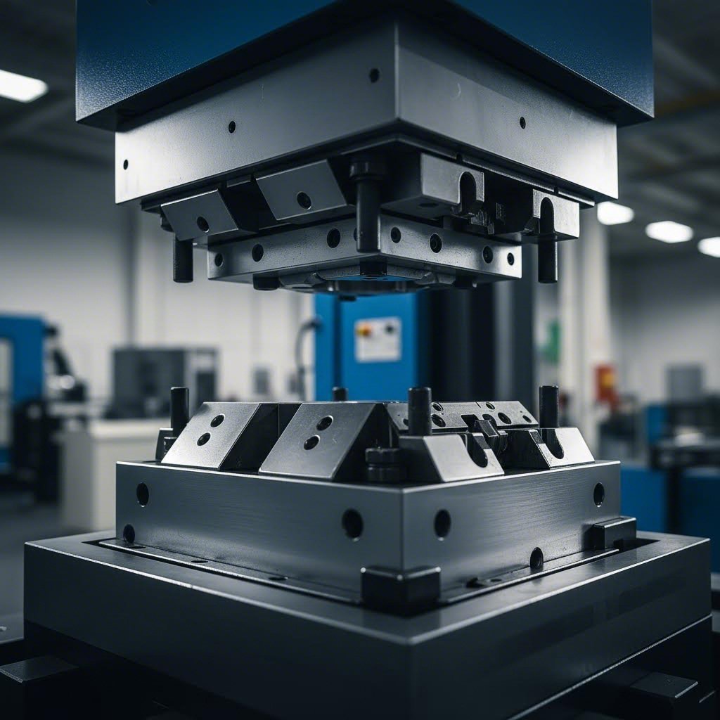
Ar kada nors domėjotės, kaip gamintojai gaminą tūkstančius identiškų metalinių detalių su puikiu tikslumu? Atsakymas slepiasi specializuotame šabloninėje įrangoje, kuri transformuoja neapdorotą lakštminio metalo medžiagą į viską – nuo išmaniųjų telefonų korpusų iki automobilių kėbulo plokščių. Taigi, kas yra šablonas gamyboje? Paprasčiausiai tariant, štampavimo šablonas – tai tiksliai suprojektuota įranga, montuojama preso mašinoje ir skirta pjauti, lenkti ar formuoti metalo lakštus į konkrečias formas su nepaprastu tikslumu.
Štampavimo šablonas – tai tikslus įrankis, kuris pjauta ir formuoja metalus į funkcinėmis formomis. Šablonas susideda iš dviejų pusių, kurios įdedamos į presą, gebantį sukurti pakankamą jėgą, kad būtų atliekamos reikiamos šablono funkcijos, įskaitant pjovimą, lenkimą, skverbtinį (piercing) apdorojimą, reljefinį (embossing) apdorojimą, formavimą, traukimą (drawing), ištempimą (stretching), monetinį (coining) apdorojimą ir ekstruziją.
Kiekvienos metalinės detalės gamybos pagrindas
Norint suprasti, kas yra spausdinimas, reikia suprasti, kaip šios spausdinimo priemonės veikia kaip šiuolaikinės masinės gamybos pagrindas. Šablonas susideda iš dviejų pagrindinių pusės, viršutinės ir apačios dalies, kurios veikia kartu kaip labai sudėtingas metalo kepsnių pjoviklis - Ne. Kai spausdintuvas užsidaro, šios pusės turi didžiulę jėgą, kad plokštus lakštus paverstų triumais.
Kas yra metalo spausdinimas be tinkamo įrankio? Iš esmės neįmanoma. Automobilių, kosmoso ir elektronikos pramonės šakos labai priklauso nuo šių įrankių, nes jie suteikia neprilygstamą nuoseklumą. Kai sukuriate spausdinimo formą, ji gali gaminti šimtus tūkstančių identiškų dalių, užtikrinant, kad kiekvienas komponentas atitiktų tikslias specifikacijas.
Iš žaliavinio lakšto į precisiją
Magija įvyksta, kai metalas patenka į šabloną. Kiekvienoje presavimo ciklo fazėje šablonas atlieka keturias esmines funkcijas: nustato medžiagos padėtį, patikimai ją pritvirtina, apdoroja metalą įvairiomis operacijomis ir išleidžia paruoštą detalę. Nors šablonų pjovimas ir formavimas gali atrodyti paprasti, šių procesų inžinerija reikalauja itin dėmesingos smulkmenų analizės.
Kodėl tai svarbu jums? Arba jūs perkate detalių naujam produktui, arba tyrinėjate gamybos galimybes – suprasdami, kas yra šablonai gamyboje, galėsite priimti informuotus sprendimus. Ši instrukcija nuvesta jus per viską – nuo šablonų sandaros ir tipų iki medžiagų pasirinkimo ir problemų šalinimo, suteikdama žinių, kurios leis jums tikrai pasitikėti savo kitu kaladėliavimo projektu.
Esminiai kaladėliavimo šablonų komponentai paaiškinti
Įsivaizduokite štampavimo šabloną kaip puikiai sureguliuotą orkestrą — kiekvienas komponentas atlieka savitą vaidmenį, tačiau visi jie turi veikti idealioje harmonijoje, kad būtų gaminamos be priekaištų metalinės detalės. Suprasdami, kaip šie elementai vienas su kitu sąveikauja, suprantate, kodėl tikslus įrankis yra toks svarbus ir kaip kiekvienas jo elementas prisideda prie matmeninės tikslumo užtikrinimo. Panagrinėkime metalinės skylutės ir šablono sistemos sandarą detalė po detalės.
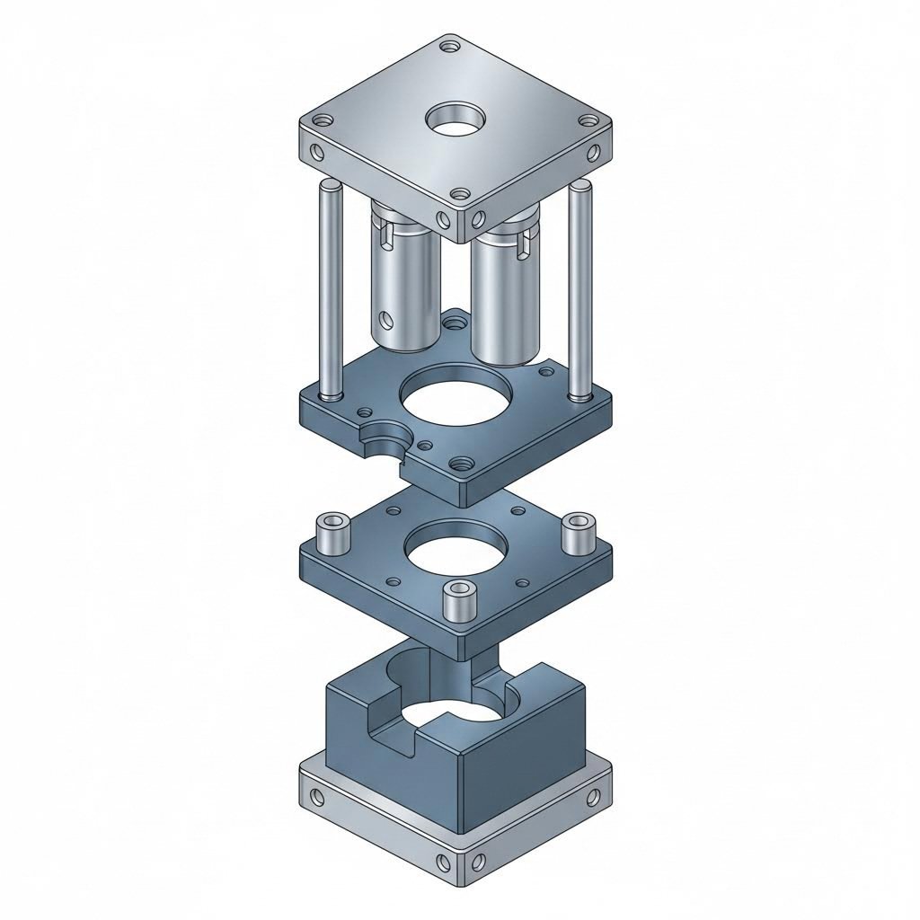
Visas šablono komplektas susideda iš kelių esminių elementų, kurių kiekvienas sukurtas tam tikroms funkcijoms atlikti štampavimo ciklo metu:
- Stūmoklis: Vyrinis komponentas, kuris įeina į šablono ertmę ir tiesiogiai veikdamas medžiagą ją supjausto arba suformuoja į reikiamą formą
- Formos blokas: Moterinis komponentas, turintis ertmę arba angą, kuri priima skylutę ir nulemia galutinės detalės geometriją
- Išstūmimo plokštė: Laiko apdorojamą detalę plokščiai operacijų metu ir nuima medžiagą nuo skylutės po formavimo ar pjovimo
- Vadovaujantys kaiščiai ir įmovos: Tikslaus išdėstymo komponentai, užtikrinantys, kad viršutinė ir apatinė šablono dalys kiekviename cikle susitiktų tobuloje atitiktyje
- Remiamosios plokštės: Paramos konstrukcijos, kurios neleidžia štampavimo matricos blokui ir kalno deformuotis esant ekstremaliai dideliam slėgiui
- Štampavimo matrica (viršutinė ir apatinė padėklų plokštė): Rėminė konstrukcija, kuri visus komponentus laiko tinkamoje padėtyje visą veikimo laiką
Štampavimo matricos bloko ir kalno montažo viduje
Kalno ir matricos sąveika sudaro kiekvienos štampavimo operacijos širdį. Įsivaizduokite kalną kaip tiksliai suformuotą plaktuką o štampavimo matricos bloką – kaip jam atitinkantį įkalnį. Kai presas užsidaro, kalnas nusileidžia į štampavimo matricos bloko ertmę, o kartu jie plokščią metalo lakštą transformuoja į norimą detalę.
Štampavimo matricos bloke yra tiksliai apdirbtos ertmės, kurios tiksliai atitinka reikiamą formą. Pagal gamybos specifikacijas šis komponentas turi išlaikyti pakartotinius aukšto slėgio smūgius, vienu metu išlaikydamas matmeninę stabilumą. Būtent čia į žaidimą įeina preso plokštė ir atraminės plokštės – jos vienodai paskirsto apkrovas ir neleidžia štampavimo matricos blokui išsivystyti laikui bėgant.
Kas daro šią sąsają ypatinga? Tarp įrankio ir matricos tarpas – paprastai matuojamas tūkstantosiomis colio dalimis – nulemia krašto kokybę, šukų susidarymą ir visumos detalės tikslumą. Per arti vienas kito – ir įrankiai per greitai susidėvi. Per toli vienas nuo kito – ir jūsų detalėse susidaro nepriimtini šukai. Šis kritinis nuokrypis yra priežastis, kodėl įrankių brėžinių specifikacijos projektavimo etape reikalauja tokios dėmesingos inžinerinės kvalifikacijos.
Atskyrimo plokštė šiame įrenginyje atlieka dvigubą funkciją. Pirma, ji laiko medžiagą plokščiai ant matricos bloko operacijų metu, neleisdama jai judėti ir taip išvengiant matmeninių klaidų. Antra, kai spaustuvės įrankis baigia savo judėjimą, atskyrimo plokštė nuima apdorojamą detalę nuo įrankio, užtikrindama švarų atskyrimą ir paruošdama kitam ciklui.
Tikslumo užtikrinantys orientaciniai sistemos
Ar kada nors domėjotės, kaip šablonų štampai išlaiko tikslumą po milijonų ciklų? Atsakymas slepiasi vedamųjų sistemose. Vedamosios rankenėlės ir įvorės sudaro tikslų lygiavimo mechanizmą, kuris visą laiką užtikrina viršutinės ir apatinės štampo dalies idealų sinchronizavimą kiekviename stūmoklio judėjime.
Štai kaip tai veikia: vedamosios rankenėlės – dažniausiai kietintos plieno cilindrinės detalės – pritvirtinamos prie vienos štampo rinkinio dalies. Priešingosios štampo rinkinio dalies įvorės priima šias rankenėles, kai presas užsidaro. Ši išdėstymo schema pašalina šoninį judėjimą, užtikrindama, kad štampo smaigalys kiekvieną kartą įeitų į štampo bloko ertmę tiksliai tuo pačiu padėtimi.
Paties štampo rinkinio – kurį sudaro viršutinė ir apatinė padėklai, sujungti vedamąja sistema – funkcija yra suteikti konstrukcinę pagrindą visoms kitoms komponentėms. Galima jį laikyti kaip rėmą, kuris viską laiko tinkamoje padėtyje. Be standaus ir gerai suviršutinės bei apatinės padėklų lygiuoto štampo rinkinio net ir labiausiai tiksliai apdirbtas smaigalys bei štampas duotų nevienodų rezultatų.
Kitos komponentės papildo sistemos funkcionalumą:
- Vadovai: Maži žymekliai, kurie nustato ir išlygina medžiagą štampavimo įrankyje, užtikrindami nuolatinę padėtį kiekvienai operacijai
- Spyruoklės: Užtikrina grąžinamąjį judėjimą judančioms detalėms ir kontroliuojamą slėgį formavimo operacijų metu
- Išstumiamieji elementai ir išstumiamieji strypai: Pašalina pagamintas dalis iš štampavimo įrankio ertmės, neleisdami jiems prilipti ir leisdami tęsti nuolatinę gamybą
Kai visi šie komponentai veikia kartu – nuo spaustuvės įrankio rėmo iki mažiausio žymeklio – pasiekiamas pakartojamumas, kuris padaro masinį štampavimą ekonomiškai naudingą. Šios tarpusavio sąveikos supratimas padeda atpažinti aukštos kokybės įrankius ir veiksmingai bendrauti su štampavimo įrankių gamintojais dėl jūsų gamybos reikalavimų.
Štampavimo šablonų tipai ir jų taikymo sritys
Dabar, kai suprantate, kaip štampavimo šablonų komponentai veikia kartu, tikriausiai svarstote: kuris štampavimo šablonų tipas tinka jūsų projektui? Štampavimo šablonų pasirinkimas nėra tik techninių specifikacijų klausimas – tai reiškia, kad jūsų gamybos tikslus reikia suderinti su tinkama įrankių strategija. Pažvelkime į keturis pagrindinius metalo štampavimo šablonų tipus ir išsiaiškinkime, kada kiekvienas iš jų duoda optimalius rezultatus.
Atminte apie štampavimo šablonų pasirinkimas panašu į tinkamo transporto priemonės pasirinkimą kelionėje. Kompaktiškas automobilis puikiai tinka mieste važinėti, tačiau sunkiems kroviniams vežti reikėtų pikapo. Panašiai kiekvienas šablonų tipas ypač gerai tinka tam tikroms situacijoms, remiantis detalės sudėtingumu, gamybos apimtimis ir sąnaudų sumą.
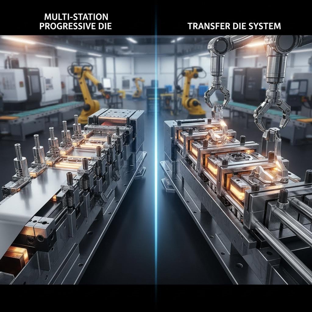
Progresyvinės iškirptuvės didelėms serijoms
Įsivaizduokite surinkimo liniją, kur kiekviena stotis atlieka vieną konkrečią užduotį – būtent taip veikia progresyvieji štampavimo įtaisai. Šie lakštinių metalų štampavimo įtaisai susideda iš kelių nuosekliai išdėstytų stočių, kai kiekviena stotis atlieka atskirą operaciją, o metalinė juosta juda per presą. Medžiaga tolygiai paduodama iš ritės ir juda iš vienos stoties į kitą, kol galutinis gaminys išeina linijos pabaigoje.
Kodėl progresyvieji štampavimo įtaisai yra tokie populiarūs štampavimo operacijose? Pagal „Durex Inc.“ duomenis, progresyvieji štampavimo įtaisai užtikrina didelę našumą ir leidžia greitai gaminti didelius detalių kiekius, tuo pačiu užtikrindami visų pagamintų komponentų vienodumą. Jie dažnai naudojami automobilių pramonėje gaminti laikikliams ir spaustukams, o elektronikoje – sudėtingoms detalėms, reikalaujančioms nuolatinės tikslumo palaikymo.
Štai kodėl gamintojai juos mėgsta:
- Greitis: Kiekvienas preso spustelėjimas sukuria po vieną detalę, maksimaliai padidinant gamybą
- Konsistingumas: Kiekvienas komponentas atitinka identiškus techninius reikalavimus
- Automatizacijos prieštaringumas: Minimalus rankinis apdirbimas sumažina darbo jėgos sąnaudas
- Medžiagos naudojimo efektyvumas: Juostos tiekimas sumažina atliekas, kai jis tinkamai suprojektuotas
Tačiau progresyvūs šablonai nėra optimalus sprendimas kiekvienai situacijai. Pradinė įrankių gamybos investicija yra didesnė nei paprastesnių variantų, o jie geriausiai tinka mažesniems ar vidutinio dydžio detalių gamybai iš nuolatinės juostos medžiagos. Sudėtingos trimatės formos gali reikšti alternatyvių metodų taikymą.
Kada perduodamieji šablonai pranašesni už progresyviuosius sistemų
Ką daryti, kai jūsų detalės per didelės ar per sudėtingos progresyviems šablonams? Štai kur puikiai tinka perduodamieji šablonai. Skirtingai nuo progresyvių sistemų, kur medžiaga visą laiką lieka sujungta, perduodamieji šablonai naudoja mechaninius arba automatizuotus perduodamųjų mechanizmų prietaisus, kad perkelia atskiras заготовkes tarp atskirų stotyčių.
Įsivaizduokite patyrusį amatininką, kuris perduoda apdorojamą detalę iš vienos specializuotos darbo vietos į kitą – kiekviena vieta prideda savo indėlį, kol galiausiai susiformuoja galutinis gaminys. Kaip nurodo „Worthy Hardware“, perkėlimo šablonų (transfer die) štampavimas suteikia didesnį lankstumą detales tvarkant ir orientuojant, todėl jis ypač tinka sudėtingoms konstrukcijoms ir formoms, kurių negali apdoroti nuoseklūs šablonai (progressive dies).
Perkėlimo šablonai ypač naudingi, kai reikia:
- Didelių detalių, viršijančių nuoseklių šablonų dydžio ribas
- Sudėtingų trimatės geometrijos formų, reikalaujančių kelių orientacijų
- Gilių įtraukimų arba reikšmingų formavimo operacijų
- Lankstumo įtraukti į vieną gamybos ciklą įvairias operacijas, pvz., skylėjimą, lenkimą, įtraukimą ir apdirbimą kraštų
Ką reikia atsižvelgti? Šios technologijos eksploatacinės sąnaudos yra didesnės, o paruošimo laikas ilgesnis nei nuoseklių šablonų atveju. Taip pat reikės patyrusių operatorių priežiūrai ir šablonų reguliavimui. Tačiau sudėtingoms montuojamoms sistemoms, naudojamoms aviacijoje, sunkiojoje mašinų statyboje arba didelėse automobilių detalių gamybose, perkėlimo šablonai dažnai būna neatsiejami.
Sudėtiniai štampai: keli veiksmai vienu spaudimo judesiu
Kartais paprastumas laimi. Sudėtiniai štampai vienu spaustuvės judesiu vienu metu atlieka kelis pjovimo veiksmus – įsivaizduokite pjovimo štampą, kuris išpjauta detalės išorinį kontūrą tuo pačiu metu, kai praduria vidinius skyles. Šis metodas pašalina būtinybę perduoti medžiagą tarp stotyčių.
Pagal pramonės šaltinius, sudėtiniai štampai integruoja tokius veiksmus kaip pjovimas, lenkimas ir reljefinis spausdinimas viename štampo rinkinyje, žymiai sutrumpindami gamybos trukmę ir padidindami našumą. Jie ypač efektyvūs, kai reikia:
- Plokščių detalių su tiksliais tarpusavio matmenų nuoseklumo reikalavimais
- Vidutinės gamybos apimties, kai svarbūs įrankių kainos
- Detalių, kurioms reikalinga tikslūs daugelio pjovimo elementų tarpusavio išdėstymas
Kadangi visos operacijos vyksta vienu metu, sudėtiniai štampai pašalina galimus nesutapimo problemas, kurios gali kilti, kai detalės juda tarp stotyčių. Tačiau jie riboti palyginti paprastomis geometrijomis – daugiausia plokščiomis detalėmis be sudėtingų formavimo reikalavimų.
Kombinuoti štampai: geriausias abiejų pasaulių sprendimas
Kai reikia tiek pjovimo, tiek formavimo operacijų, bet norite sumažinti įrankių sudėtingumą, kombinuoti štampai siūlo patrauklų sprendimą. Šie universalūs įrankiai veikia kaip hibridinis metalo štampavimo įrankis, atliekantys tiek pjovimo, tiek nepjovimo operacijas (pvz., lenkimo ar traukimo) vienu smūgiu.
Kombinuoti štampai užpildo spragą tarp tikrųjų pjovimo įrankių ir sudėtingų formavimo sistemų. Jie ypač tinkami detalėms, kurioms reikia apibrėžtos pjovimo kontūros kartu su paprastomis formavimo savybėmis – taip išvengiama investicijų į kelis atskirus štampus, o gamybos efektyvumas lieka aukštas.
Štampų tipų palyginimas: kuris iš jų tinka jūsų projektui?
Teisingos štampavimo šablonų rūšies parinkimas reikalauja įvertinti kelis veiksnius, atsižvelgiant į jūsų konkrečius reikalavimus. Žemiau pateikta lyginamoji lentelė, kurioje išskleidžiami pagrindiniai sprendimų priėmimo kriterijai:
| Koeficientas | Progresyvios mirtys | Pervadiniai šablonai | Sudėtinės formos | Kombinuoti šablonai |
|---|---|---|---|---|
| Operacijos sudėtingumas | Keli nuoseklūs procesai | Keli procesai su detalės pernešimu | Keli vienu metu vykstantys pjovimo procesai | Vienoje eigoje – pjovimas ir formavimas |
| Gaminių kiekis | Didelis gamybos apimtis (daugiau kaip 100 000 detalių) | Vidutinė–aukšta apimtis | Žema–vidutinė apimtis | Žema–vidutinė apimtis |
| Detalės dydžio diapazonas | Mažos iki vidutinio dydžio detalės | Vidutinio iki didelio dydžio detalės | Mažos iki vidutinio dydžio plokščios detalės | Mažos iki vidutinio dydžio detalės |
| Sudėjimo laikas | Vidutinis (reikia sukti spyruoklinį įtaisą) | Ilgesnis (perduodamosios sistemos kalibravimas) | Greitas (vienos stoties veikimas) | Nuo greito iki vidutinio |
| Tipinės taikymo sritys | Automobilių laikikliai, elektroniniai komponentai, tvirtinamieji elementai | Lėktuvų surinkimai, dideli automobilių skydai, buitinės technikos detalės | Žiedai, tarpinės, tikslūs plokščios detalės | Detalės, kurioms reikia pjautų profilių su paprastais lenkimais |
| Pradinė įrankių kaina | Aukštesnis | Aukščiausias | Žemesnis | Vidutinis |
| Kaina vienam vienetui esant dideliam kiekiui | Žemiausias | Vidutinis | Vidutinis | Vidutinis |
Skamba sudėtingai? Štai greitas sprendimų priėmimo rėmas: pradėkite nuo savo metinių gamybos apimčių. Jei gaminate šimtus tūkstančių mažesnių detalių, progresyvūs šablonai dažniausiai užtikrina geriausią ekonominį efektą. Didelėms, sudėtingoms detalėms arba mažesnėms gamybos apimtims perduodamieji arba sudėtiniai šablonai gali būti naudingiau naudoti, net jei vienos detalės kaina yra aukštesnė.
Medžiagos tipas ir storis taip pat įtakoja jūsų pasirinkimą. Storesnės medžiagos ar kietesnės lydinio rūšys gali reikalauti perduodamosios sistemos kontroliuojamo formavimo galimybių, tuo tarpu plonesnės medžiagos puikiai tinka aukšto greičio progresyviems procesams.
Suprantant šiuos skirtumus, galėsite deramai bendrauti su štampavimo šablonų gamintojais apie savo specifinius poreikius. Tačiau šablonų tipas yra tik viena iš lygties sudedamųjų dalių – medžiagos, iš kurių gaminami jūsų įrankiai, labai paveikia jų našumą, tarnavimo trukmę ir galiausiai gamybos kaštus.
Šablonų medžiagos ir atrankos kriterijai
Jūs jau pasirinkote šablonų tipą – bet iš ko jis turėtų būti pagamintas? Plieno štampavimo šablonų viduje esančios medžiagos tiesiogiai nulemia jūsų įrankių tarnavimo trukmę, detalių tikslumą ir galiausiai kiekvienos detalės gamybos kaštus. Galvokite taip: šablonų medžiagų parinkimas panašus į tinkamų produktų parinkimą receptui. Net idealiai taikant techniką, prastos kokybės produktai duoda nusivylimą keliančius rezultatus.
Taigi, kas iš tikrųjų yra įrankių ir šablonų medžiagų pasirinkimas? Tai keturių pagrindinių veiksnių subalansavimas: kietumas dėl dilimo atsparumo, stiprumas, kad būtų išvengta įtrūkimų, šilumos atsparumas aukšto greičio operacijoms ir sąnaudų efektyvumas jūsų gamybos apimčiai. Pažvelkime, kaip skirtingos medžiagos atitinka šiuos reikalavimus.
Įrankių plieno rūšys ir jų eksploatacinės savybės
Įrankių plienas sudaro daugumos metalinių šablonų taikymo pagrindą. Pagal Ryerson išsamų vadovą, įrankių plienas turi nuo 0,5 % iki 1,5 % anglies bei karbidus sudarančių elementų, tokių kaip volframas, chromas, vanadis ir molibdenas. Šie lydiniai užtikrina kietumą, nusidėvėjimui atsparumą ir matmeninę stabilumą, kurie reikalingi šablonų gamyboje.
Štai dažniausiai pasitaikančios rūšys, su kuriomis susidursite įrankių ir šablonų gamyboje:
- D2 Įrankių plienas: Didelio anglies ir chromo kiekio plienas, pasižymintis išsklitančiu dėvėjimosi atsparumu. Po kalimo pasiekia 62–64 HRC kietumą; D2 puikiai tinka ilgalaikėms įrankių gamybos aplikacijoms, pvz., iškirpimo ir skylių daužymo šablonams, kur reikalingos tikslūs matmenys. Jo kietieji karbidiniai dalelių įtraukimai užtikrina puikų abrazyvinį atsparumą didelės apimties gamybai.
- A2 įrankinė plienas: Orą kietinantis plienas, žinomas tuo, kad puikiai derina stiprumą su dėvėjimosi atsparumu. Turėdamas 5 % chromo kiekį, pasiekia 63–65 HRC kietumą; A2 užtikrina puikią matmeninę stabilumą – todėl jis idealus iškirpimo smaigiams, formavimo šablonams ir injekcinio liejimo aplikacijoms, kur tikslumas yra lemiamas veiksnys.
- S7 įrankių plienas: Šoko atsparumo čempionas. Kai jūsų gamybos įrankiai patiria reikšmingą mechaninį poveikį, S7 nepaprastas stiprumas neleidžia jiems suskilti ar suskilti. Pasiekdamas 60–62 HRC kietumą, šis orą kietinantis plienas puikiai tinka kirviams, smaigiams ir kniedėms, kur šoko atsparumas svarbesnis nei maksimalus kietumas.
- M2 formos plienas: Aukšto greičio plienas, kuris išlaiko aštrumą esant padidėjusiai temperatūrai. Maždaug 62–64 HRC kietumo M2 plienas užtikrina puikią smūgio atsparumą ir dilimo atsparumą pjovimo įrankiams, tokiems kaip gręžtuvai ir sriegyklos, taip pat štampavimo šablonams, veikiantiems didesniais greičiais, kai kyla susirūpinimas dėl šilumos kaupimosi.
Pastebėjote, kaip kiekvienas plieno tipas siūlo skirtingas privalumus? D2 plienas pirmiausia akcentuoja dilimo atsparumą ilgoms gamybos serijoms, o S7 plienas šiek tiek paaukoja kietumą, kad pasiektų geresnį smūgio atsparumą. Šių kompromisų supratimas padeda parinkti tinkamiausius plieninius štampavimo įrankius konkrečioms jūsų taikymo sąlygoms.
Karbido įdėklai ilgesniam šablonų tarnavimo laikui
Kai įprastinis įrankių plienas nepakankamai atsparus smūgiams arba kai štampuojate labai abrazyvias medžiagas itin dideliais kiekiais, karbido įdėklai tampa jūsų slaptuoju ginklu. Šie volframą ir anglį turintys junginiai užtikrina nepaprastą kietumą ir dilimo atsparumą, kurie žymiai viršija įprastų plieninių įrankių galimybes .
Kodėl verta apsvarstyti karbido naudojimą metalinių šablonų taikymuose?
- Išskirtinė tvirtumas: Karbidas išlaiko pjovimo briauną žymiai ilgesnį laiką nei įrankių plienas, todėl sumažėja keitimo dažnumas ir gamybos prastovos
- Šilumos varžymas: Karbidas atlaiko padidėjusias temperatūras neprizaudydamas kietumo – tai ypač svarbu aukšto greičio štampavimo operacijoms
- Abrazyvių medžiagų apdorojimo galimybė: Štampuojant nerūdijančiąją plieną, kietintus lydinius ar kitas labai dėvėjamosioms sąlygoms skirtas medžiagas karbido įdėklai tarnauja žymiai ilgiau nei plieniniai analogai
- Tikslus techninis aptarnavimas: Medžiagos matmeninė stabilumas užtikrina nuolatinę detalės kokybę visą ilgą gamybos ciklą
Karbido įdėklai dažnai naudojami įrankių ir šablonų gamyboje, ypač formų ir šablonų, kurie turi atlaikyti intensyvų dėvėjimąsi. Kokia kaina už tai? Aukštesnė pradinė kaina palyginti su įrankių plieno kaina. Tačiau didelėse gamybos apimtyse, kai ilgaamžiškumas lemia bendrą ekonominę naudą, karbidas dažnai užtikrina geresnę bendrą savininkystės kainą.
Medžiagų pasirinkimas remiantis jūsų gamybos reikalavimais
Šių variantų pasirinkimas reikalauja įvertinti jūsų konkrečią situaciją. Kaip nurodyta CMD PPL , tinkama medžiagų parinktis žymiai veikia štampavimo įrankių našumą, gamybos efektyvumą ir gaminamų detalių kokybę. Įvertinkite šiuos veiksnius:
- Gaminių apimtys: Didelės serijos pagrindžia kietųjų lydinių ar aukštos kokybės įrankių plienų, pvz., D2, naudojimą, tuo tarpu mažesnėms serijoms pakankamai tinka ekonomiškesnės alternatyvos
- Apdorojamojo gaminio medžiagos kietumas: Kietųjų ar abrazyvių medžiagų štampavimui reikalingos kietesnės štampavimo įrankių medžiagos – kietieji lydiniai ar chromo turintys aukšto kiekio plienai atsparūs stiprių apdorojamųjų gaminių sukeliamam nusidėvėjimui
- Tolerancijos reikalavimai: Tikslūs leistinieji nuokrypiai reikalauja medžiagų, kurios išlaiko puikią matmeninę stabilumą, pvz., A2 ar D2, kad būtų išlaikyta tikslumas milijonams ciklų
- Biudžeto apribojimai: Suderinkite pradines įrankių gamybos sąnaudas su ilgalaikėmis sąnaudomis, įskaitant keičiamų įrankių sąnaudas, gamybos sustojimus ir netinkamų detalių atmetimo normas
- Eksploatacijos temperatūros: Didelės našumo veikimo režimu vykstantys procesai sukuria reikšmingą šilumą – pasirinkite medžiagas, pvz., M2 ar kietuosius lydinius, kurios išlaiko kietumą esant padidėjusiai temperatūrai
Prisiminkite: šablonai, pagaminti iš tvirtų medžiagų su aukšta dėvėjimosi atsparumu, ilgainiui reikalauja mažiau priežiūros ir keitimo. Tai sumažina susijusias sąnaudas ir prastovas, tuo pačiu užtikrinant nuolatinį gamybos grafiką. Teisingas medžiagos pasirinkimas – tai ne tik pradinės sąnaudos, bet ir visos gamybos ekonomika.
Dabar, kai aiškūs šablonų tipai ir medžiagos, kaip iš tikrųjų pasirinkti tinkamiausią kombinaciją savo konkrečiam projektui? Sprendimų priėmimo procesas apima kelių veiksnių svertinimą atsižvelgiant į jūsų unikalius reikalavimus.
Kaip pasirinkti tinkamą įrankį savo taikymui
Jūs jau susipažinote su šablonų tipais, medžiagomis ir komponentais – bet kaip iš tikrųjų pasirinkti tinkamiausią variantą savo konkrečiam projektui? Šablonų parinkimas spaustuvų operacijoms nereiškia pasirinkti pačios pažangiausios ar brangiausios galimybės. Tai reiškia, kad jūsų gamybos reikalavimai turi būti suderinti su įrankiais, kurie užtikrina optimalius rezultatus geriausiomis bendromis sąnaudomis. Panagrinėkime praktinę sprendimų priėmimo schemą, kuri sudėtingus kintamuosius paverčia aiškiais pasirinkimais.
Įsivaizduokite šį procesą kaip dėlionės surinkimą. Kiekvienas veiksnys – detalės geometrija, apimtis, medžiaga, tikslumas ir biudžetas – yra dėlionės dalis, kuri susideda į jūsų idealų sprendimą. Kai suprantate, kaip šios dalys tarpusavyje sąveikauja, metalo štampavimo procesas tampa žymiai mažiau paslaptingas.
- Apibrėžkite savo detalės geometriją ir sudėtingumą: Pradėkite nuo to, ką tiksliai gaminsite. Ar tai paprastas plokščias žiedas ar sudėtingas trimatis laikiklis? Ar reikia kelių lenkimų, ištraukimų ar formavimo operacijų? Sudėtingos geometrijos dažniausiai nukreipia jus į progresyviuosius arba perduodamuosius šablonus, tuo tarpu paprastesnės formos gali puikiai tiktis sudėtiniam įrankiui.
- Apskaičiuokite metinę gamybos apimtį: Kiek detalių jums reikia per metus? Apimtis labai paveikia šabloninio preso pasirinkimą, nes didesnės partijos pateisina didesnes įrankių investicijas, kurios ilgainiui sumažina vienos detalės gamybos sąnaudas.
- Nustatykite medžiagos tipą ir storį: Kokį metalą jūs štampuojate? Aliuminis elgiasi kitaip nei nerūdijantis plienas, o medžiagos storis veikia formavimo jėgas, štampo dilimą ir įrankių reikalavimus.
- Nustatykite tikslumo reikalavimus: Kiek tikslūs turi būti jūsų gaminami detalės? Griežtesni tikslumai reikalauja sudėtingesnių įrankių ir medžiagų – tai padidina tiek pradines sąnaudas, tiek nuolatines priežiūros išlaidas.
- Nustatykite realistinius biudžeto parametrus: Suderinkite pradines įrankių investicijas su ilgalaikių gamybos ekonomika. Kartais didesnės pradinės išlaidos per visą štampo tarnavimo laiką leidžia žymiai sutaupyti.
Štampo tipo parinkimas pagal gamybos apimtis
Gamybos apimtys, matyt, yra svarbiausias veiksnys, lemiantis štampo pasirinkimą. Štai kodėl: štampavimo gamybos ekonomika radikaliai keičiasi priklausomai nuo to, kiek detalių jūs gaminsite.
Mažoms gamybos serijoms – pavyzdžiui, mažiau nei 10 000 detalių per metus – dažnai naudingiau naudoti paprastesnius šablonus. Sudėtiniai šablonai ar net rankiniai darbai gali pasirodyti ekonomiškesni, nes detalės gaminamos ne taip daug, kad būtų galima išsklaidyti brangios progresyvios šabloninės įrangos sąnaudas. Pag according to Zintilon šablonų parinkimo vadovo, tikslus metinis gamybos apimties įvertinimas yra esminis veiksnys, priimant sprendimą dėl įvairių šablonų tipų investicijos pagrindimo.
Vidutinės gamybos apimties gamyba (10 000–100 000 detalių) suteikia daugiau galimybių. Kombinuoti šablonai ar paprastesnės progresyvios sistemos pradeda tapti ekonomiškai naudingi, nes vienos detalės šabloninės sąnaudos išsisklaido per didesnį kiekį vienetų. Reikės išanalizuoti ribinį tašką, kai didesnės pradinės investicijos leidžia pasiekti žemesnes bendras sąnaudas.
Didelio apimties operacijos – šimtai tūkstančių ar net milijonai detalių – beveik visada rodo į progresyviuosius štampavimo šablonus lakštinių metalų štampavimo taikymuose. Pradinė įrankių gamybos investicija, nors ir didelė, tampa nepastebima, kai ji paskirstoma per milžiniškus gamybos apimtis. Be to, progresyviosios sistemos maksimaliai išnaudoja presus ir sumažina darbo sąnaudas vienai detalei.
Taip pat įvertinkite galimus apimčių pokyčius. Jei numatote augimą, dabartinė investicija į pajėgesnius šablonus gali vėliau išvengti brangios peršablonavimo procedūros. Atvirkščiai, neaiški paklausa gali reikšti, kad pradėti reikėtų paprastesniais šablonais, kol rinka patvirtins savo stabilumą.
Tikslumo reikalavimai, kurie lemia šablonų pasirinkimą
Kokios yra jūsų matmenų tikslumo reikalavimų ribos? Tikslumo specifikacijos fundamentaliai formuoja jūsų metalo štampavimo sprendimus – nuo šablono tipo iki medžiagos pasirinkimo ir techninės priežiūros grafiko.
Pagal Interstate Specialty Products tikslumo vadovas iškirpimo tikslumo nuokrypiai žymiai skiriasi priklausomai nuo įrankių tipo. Atitinkamų metalinių (vyriškoji/ moteriškoji) formų tikslumas yra didžiausias – nuo 0,001" iki 0,005", o plieninės taisyklės formos paprastai užtikrina tikslumą nuo 0,010" iki 0,015". Kietos, frezuotos formos užima vidurinę padėtį – nuo 0,005" iki 0,010".
Štai kaip tikslumo reikalavimai sąveikauja su kitais veiksniais:
- Aukštas tikslumas + didelis apimtis: Investuokite į tikslų progresyvią įrankių sistemą su kietintais komponentais ir patikimomis orientacinėmis sistemomis. Nuoseklumas atsipildo milijonams ciklų.
- Aukštas tikslumas + maža apimtis: Atitinkamos metalinės sudėtinės formos gali užtikrinti reikiamą tikslumą be progresyvių formų investicijų.
- Vidutinis tikslumas + didelis apimtis: Standartinės progresyvios formos veikia puikiai – nereikia brangių, ypatingo tikslumo formų.
- Žemas tikslumas + bet kokia apimtis: Dėmesys turėtų būti sutelktas į greitį ir kainą, o ne į brangius įrankius. Paprastos formos dažnai pakanka.
Prisiminkite, kad tolerancijų galimybės priklauso ne tik nuo štampo tipo. Medžiagos savybės, preso būklė ir priežiūros praktika visos veikia matmeninę vientisumą. Kietesnės medžiagos gali rodyti atšokimą, kuriam reikia kompensacijos štampo projektavime, o minkštesni metalai gali deformuotis per tvarkymą.
Preso ir štampo sąveikos supratimas
Jūsų štampo preso galimybės tiesiogiai apriboja įrankių parinkimo galimybes. Prieš galutinai pasirenkant štampą, įvertinkite šiuos preso parametrus:
- Našumas tonomis: Ar jūsų presas sukuria pakankamą jėgą numatytoms operacijoms? Reikalinga tonacija priklauso nuo medžiagos storio, kietumo ir detalės sudėtingumo.
- Lovos dydis: Ar jūsų štampas tilps į preso darbinę erdvę? Atsižvelkite ne tik į štampo matmenis, bet taip pat į tiekimo mechanizmus ir detalės išmetimo reikalavimus.
- Ėjimo ilgis: Ar stumbro kelias yra pakankamas jūsų formavimo operacijoms? Giliems trapecijoms reikia ilgesnių judėjimų nei paprastam išpjovimui.
- Greičio galimybės: Ar presas atitinka jūsų gamybos našumo reikalavimus? Progresyviosios šabloninės matricos reikalauja presų, gebančių užtikrinti didesnį įspaudų dažnį.
Metalo štampavimo procesas veikia geriausiai, kai šabloninė matrica ir presas tinkamai suderinti. Per mažas presas apkrauna komponentus ir sutrumpina matricos tarnavimo laiką, o per didelis presas švaisto energiją ir kapitalą. Dirbkite su savo šabloninės matricos gamintoju, kad užtikrintumėte suderinamumą prieš įsipareigojant įsigyti technologinę įrangą.
Biudžeto ir gamybos ekonomikos balansavimas
Metalinių detalių štampavimo sprendimai galiausiai priklauso nuo ekonomikos. Pradinė šabloninės matricos kaina yra tik viena finansinės galvosūkio dalis – vertinkite visą vaizdą:
- Įrankių investicijos: Kokia pradinė šabloninės matricos projektavimo ir gamybos kaina?
- Vienos detalės gamybos kaina: Kaip technologinės įrangos pasirinkimas veikia darbo jėgos sąnaudas, medžiagų atliekas ir ciklo trukmę?
- Priežiūros išlaidos: Kokios nuolatinės sąnaudos kils dėl šabloninės matricos priežiūros ir remonto?
- Keitimo dažnumas: Kiek kartų reikės naujos technologinės įrangos, remiantis gamybos apimtimis ir šabloninės matricos medžiagos pasirinkimu?
- Kokybės sąnaudos: Kokie yra atmestų detalių procentai ir perdaromų detalių sąnaudos, susijusios su skirtingais įrankių variantais?
Kaip nurodo „Zintilon“, štampų pasirinkimas žymiai veikia eksploatacines sąnaudas dėl mažesnio medžiagų š waste, minimalaus prastovų laiko ir ilgesnio įrankių tarnavimo laiko. Tinkamas štampas sumažina priežiūros poreikį ir mažina keitimo dažnumą — šios taupymo naudos kaupiasi visą gamybos ciklą.
Nepaleiskitės įprastos pradinės kainos šoko ir nepasirinkite netinkamų įrankių. Pavyzdžiui, 50 000 JAV dolerių kainuojantis progresyvusis štampas, gaminantis dalis po 0,03 JAV dolerio už vieną, gali būti žymiai naudingesnis nei 15 000 JAV dolerių kainuojantis sudėtinis štampas, gaminantis tas pačias dalis po 0,08 JAV dolerio už vieną — priklausomai nuo jūsų gamybos apimties. Apskaičiuokite skaičius konkrečiai jūsų situacijai.
Kai jūsų sprendimų priėmimo schema jau nustatyta, esate pasiruošę ištirti, kaip šiuolaikinė technologija keičia štampų projektavimą ir kūrimą — sumažindama riziką ir pagreitindama laiką iki gamybos pradžios.
Šiuolaikinė štampų projektavimo technologija ir CAE integracija
Įsivaizduokite, kad atrandate kritinę klaidą savo štampavimo šablonuose nebrangiuose fizinėse bandymų fazėse, o kompiuterio ekrane – savaitėmis anksčiau, nei būtų pjautas bet koks plienas. Tai ir yra šiuolaikinės štampavimo šablonų projektavimo technologijos galia, kurią ji suteikia gamybai. Šiandien šablonų mašinų kūrimas žymiai pažengė toliau nei tradicinės piešimo lentos, priimdama sudėtingas skaitmenines priemones, kurios numato problemas, optimizuoja našumą ir žymiai sutrumpina kūrimo laikotarpius.
Kaip iš tikrųjų veikia metalo štampavimo šablonų projektavimas šiuolaikinėse įmonėse? Atsakymas apima galingą CAD/CAM programinės įrangos, modeliavimo įrankių ir kompiuteriu paremtos inžinerinės analizės derinį, kuris su nepaprasta tikslumu paverčia idėjas gamybai paruošta įranga. Pažvelkime, kaip šios technologijos revoliucinėmis priemonėmis keičia šablonų procesą nuo pradinės idėjos iki galutinės gamybos.
CAD/CAM programinės įrangos taikymas šablonų projektavime
Kiekvienas tikslus štampavimo įrankis gamyboje prasideda kaip skaitmeninis modelis. Kompiuteriu paremtosios projektavimo (CAD) programinės įrangos pagalba inžinieriai gali sukurti išsamių trimačių diegiamųjų detalių vaizdų – nuo smūgio profilių iki vedamųjų smeigtukų vietos. Tačiau šiuolaikinės sistemos žymiai viršija paprastos geometrijos kūrimą.
Pagal VISI Die Tool Design dokumentacija , šiandien integruotos CAD/CAE/CAM platformos automatizuoja visus lakštinių metalų štampavimo įrankių kūrimo etapus – nuo iškirpimo ruošinio sukūrimo ir išvyniojimo iki įrankių surinkimo, jėgos skaičiavimo ir gamybos. Šios sistemos suteikia galimybes, kurios žymiai pagreitina projektavimo procesą:
- Kintamos neutraliosios plaušo linijos skaičiavimas: Tiksliai nustato neutraliąją ašį, kad būtų pagerinta iškirpimo ruošinio prognozavimo ir išvyniojimo tikslumas
- Detalės analizė ir lenkimo tyrimas: Išsamiai įvertina gamybos galimybę, pateikdama įžvalgas apie galimus formavimo ar ištempimo sunkumus
- Automatinis iškirpimo ruošinio kūrimas: Be jokio vargo išvynioja tiek paviršiaus, tiek kietųjų modelių ruošinius, kad būtų sukurta optimali išvyniota iškirpimo ruošinio forma
- Žingsnis po žingsnio išvyniojimas: Imituoja ir planuoja kiekvieną formavimo etapą, įtraukdama funkcijas tiksliai tam proceso žingsnyje
- 3D juostos projektavimas: Greitai sukuria juostų išdėstymus, pasuka ir lygina заготовkes bei dinamiškai tvarko etapus
Projektavimo ir gamybos integracija yra ypač naudinga. Šiuolaikinės platformos automatiškai generuoja gręžimo ciklus, frezavimo programas ir 3D įrankių kelius kiekvienai plokštai ir komponentui – pašalindamos rankinio programavimo klaidas ir užtikrindamos, kad realios šablonų apdorojimo sąlygos visiškai atitiktų projektavimo tikslus.
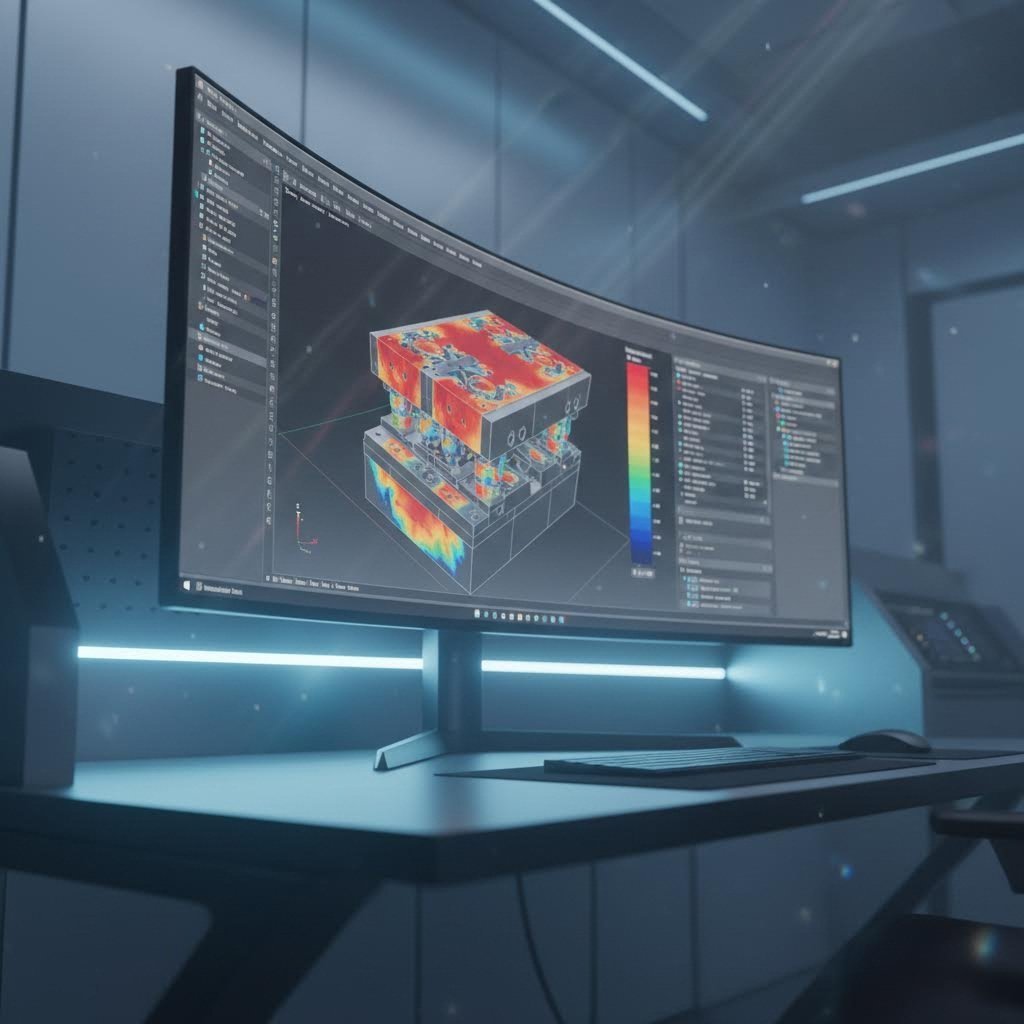
CAE imitacija šiuolaikinėje šablonų kūrimo srityje
Čia prasideda tikroji galia. Kompiuteriu paremtos inžinerinės (CAE) imitacijos leidžia inžinieriams virtualiai išbandyti šablonų veikimą dar prieš pradedant brangų šablonų gamybą. Galima tai įsivaizduoti kaip kristalinį rutulį, kuris atskleidžia, kaip jūsų šablonas elgsis realiomis gamybos sąlygomis.
Kaip išsamiai nurodyta ETA šaltinio lakštinių metalų formavimo modeliavimo vadove, šie modeliavimai leidžia inžinieriams prognozuoti ir optimizuoti lakštinių metalų elgesį formavimo operacijų metu. Ši technologija nukreipia projektavimo sprendimus, sumažina bandymų ir klaidų iteracijas bei pagerina gaminio kokybę automobilių skydų, lėktuvų komponentų ir buitinės technikos gaminiuose.
Kodėl CAE modeliavimas yra tokio didelės vertės automobilių štampavimo šablonų kūrimui? Dėl galimybės nustatyti kritinius defektus dar prieš jų atsiradimą:
- Springback prognoza: Medžiagos po formavimo jėgų pašalinimo elastingai grįžta į pradinę būseną, todėl atsiranda nuokrypiai nuo numatytų formų. Pažangus modeliavimas įvertina medžiagos anizotropiją, Bauschinger efektą ir likutines įtempius, kad tiksliai prognozuotų šį elgesį.
- Raukšlių aptikimas: Modeliavimas parodo, kur medžiagos suspaudimas gali sukelti paviršiaus defektus, leisdamas inžinieriams reguliuoti lakštinės medžiagos laikiklio jėgas arba keisti šablono geometriją.
- Plonėjimo analizė: Nustato tas vietas, kur medžiaga per daug išsitempia, kylant rizikai, kad gaminiai plyštų arba prarastų konstrukcinį stiprumą
- Medžiagos tekėjimo optimizavimas: Vaizduoja, kaip metalas juda per šabloną, leisdama reguliuoti traukos juostas, blankų laikytuvus ir šablono spindulius
Pagal Keysight analizė , detalių ir procesų projektavimo trūkumai dažnai pasireiškia tik pirmųjų bandymų metu bandymų etape – kai taisymas yra tiek laiko reikalaujantis, tiek brangus. Skaitmeninė simuliacija pašalina šią brangią problemų aptikimo fazę, nes problemas atskleidžia dar skaitmeninio projektavimo etape.
Skaitmeninis prototipavimas, kuris neleidžia kilti brangioms klaidoms
Tradicinis šablonų kūrimas buvo susijęs su nepatogiu ciklu: projektavimas, gamyba, bandymas, problemų aptikimas, modifikavimas ir pakartojimas. Kiekvienas ciklas užtrukdavo savaites ir reikalavo didelių sąnaudų. Skaitmeninis prototipavimas nutraukia šį ciklą, keisdamas kelis fizinio prototipo iteracijų ciklus į virtualius tobulinimus.
Štampavimo procesas labai naudingai naudoja pakartotinius modeliavimus. Inžinieriai atlieka kelis ciklus, koreguodami štampo įrankius ir technologinius parametrus, kad palaipsniui pasiektų pageidaujamą detalės geometriją. Kompensacinės strategijos – pvz., perlenkimas ar įrankio geometrijos keitimas – gali būti išbandytos virtualiai dar prieš jų įdiegimą.
Įvertinkite kritinius technologinius parametrus, kuriuos modeliavimas padeda optimizuoti:
- Blanko laikiklio jėga: Valdo spaudimą ant lakštinio metalo, kad būtų užkirstas kelias raukšlėms, vienu metu išvengiant plyšimų ar per didelio storio sumažėjimo
- Stačiakampio stūmiklio greitis: Turi įtakos deformacijos metu kylantiems deformacijos tempams ir medžiagos temperatūrai
- Suteptumo sąlygos: Sumažina trintį tarp įrankio ir medžiagos, užtikrindamos lygią medžiagos tekėjimą
- Temperatūros parametrai: Ypač svarbūs karštojo formavimo procesuose, kai medžiagos reakcija žymiai keičiasi
Koks rezultatas? Pirmaujantys gamintojai, naudojantys šias technologijas, pasiekia išties aukštus pirmojo praeities patvirtinimo rodiklius. 93 % pirmojo praeities patvirtinimo rodiklis šių automobilių štampavimo šablonų projektuose – tai liudija pažangios CAE integracijos galia, sujungtos su IATF 16949 sertifikuotomis kokybės valdymo sistemomis.
Kokybės valdymas pagal sertifikavimo standartus
Vien tik technologija dar nepagarantina rezultatų – sistemingas kokybės valdymas užtikrina nuolatinius pasiekimus. IATF 16949 sertifikavimas tapo automobilių šablonų gamybos etalonu, nustatant griežtus reikalavimus projektavimo patvirtinimui, proceso valdymui ir nuolatiniam tobulėjimui.
Šis sertifikavimas yra svarbus, nes jis užtikrina, kad modeliavimo rezultatai atitiktų fizinę tikrovę. Kai gamintojai sujungia pažangias CAE galimybes su sertifikuotomis kokybės sistemomis, jie tiekia įrankius, kurie veikia kaip numatyta – taip sumažindami brangius netikėtumus gamybos pradžios etape.
Skaitmeninės prototipavimo technologijos integruota su stipriąja kokybės valdymo sistema taip pat žymiai sutrumpina laiką iki gamybos pradžios. Vietoj kelių mėnesių trukmės fizinės bandymų serijos gamintojai gali per kelias savaites pereiti nuo sąvokos iki gamybai paruoštos įrangos. Kai kurie tiekėjai siūlo greitojo prototipavimo galimybes, kurios leidžia pateikti pirminius pavyzdžius jau po penkių dienų – tai būtų neįmanoma be šiuolaikinės modeliavimo technologijos prognozinės galios.
Nors štampavimo šablonų projektavimo technologija optimizuoja jūsų įrangą dar prieš pradedant gamybą, vis tiek susidursite su iššūkiais, kai prasidės štampavimo operacijos. Supratimas apie dažniausiai pasitaikančias problemas ir jų sprendimus užtikrina, kad jūsų investicija duotų maksimalią grąžą.
Dažniausiai pasitaikančių štampavimo šablonų problemų šalinimas
Net geriausiai suprojektuoti štampavimo šablonai gamybos metu susiduria su problemomis. Skirtumas tarp nedidelės nesklandumo ir brangios gamybos sustabdymo dažnai priklauso nuo to, kaip greitai diagnozuojate ir išsprendžiate problemas. Kai štampuojami detalės pradeda rodyti defektus – burbus, matmenų pasislinkimą ar paviršiaus netobulumus – žinodami jų šakninę priežastį sutaupysite valandas nevaisingų bandymų ir klaidų taisymo.
Jau pasiruošę tapti šablonų trikčių šalinimo ekspertu? Pažvelkime į dažniausiai pasitaikančias problemas, su kuriomis susidursite štampuodami lakštines metalines dalis, ir į patikrintas sprendimo priemones, kurios padės greitai grąžinti gamybą į normalią veiklos schemą.
Burbų ir kraštų kokybės problemų diagnozavimas
Burbai – tai nepatogūs iškilę kraštai arba šiurkštūs išsikišimai, susidarančios pjovimo linijose – ir tai viena dažniausių skundų štampavimo operacijose. Pagal Leelinepack defektų analizę, burbai dažniausiai atsiranda dėl per didelio įrankių ausimo arba štampavimo proceso metu įvykusios nesutapimo klaidos.
Kas sukelia burbų susidarymą jūsų štampuojamose detalėse?
- Per didelis smigiklio ir šablonų tarpas: Kai tarp smūgio įrankio ir štampavimo matricos atsiranda per didelis tarpas—dažniausiai dėl nusidėvėjimo—metalas plyšta, o ne švariai sukirpama
- Dulkiniai pjovimo kraštai: Nusidėvėjęs smūgio įrankis ar štampavimo matricos paviršius negali sukurti švaraus lūžio, kuris būtinas lygiems kraštams
- Nesuderinamumas: Kai viršutinė ir apatinė štampavimo matricos dalys nesutampa tiksliai, netolygios pjovimo jėgos sukuria netaisyklingus kraštus
- Netinkamas medžiagos pasirinkimas: Kai kurios medžiagos labiau linkusios formuoti kraštines (burr) priklausomai nuo jų kietumo ir plastikumo
Kaip pašalinti kraštines (burr)? Pradėkite nuo reguliarių įrankių patikrinimų ir aštrinimo grafikų. Pag according DGMF trikčių šalinimo vadovo, reguliarus išlyginamųjų įdėklų (alignment mandrel) naudojimas štampavimo įrenginio bokšto padėčiai tikrinti ir reguliuoti padeda išvengti netolygaus nusidėvėjimo, kuris sukelia kraštinių (burr) susidarymą. Taip pat įsitikinkite, kad parenkate išgaubtą ir įgaubtą šablonų porą su tinkamu tarpais jūsų medžiagos tipui ir storio reikalavimams
Matmenų kitimo problemų sprendimas
Kai jūsų štampuoti detalės staiga išeina iš leistinų nuokrypių ribų, gamyba sustoja. Matmenų netikslumai kelia nepatogumų kokybės kontrolės komandoms ir vėlina siuntimus – tačiau priežastys dažniausiai gali būti nustatomos sistemingai tyrinėjant.
Atšokimas yra viena sudėtingiausių matmenų problemų. Kaip paaiškina „Leelinepack“, atšokimas įvyksta tada, kai medžiaga po formavimo jėgų pašalinimo dalinai atgauna savo pradinę formą. Ši problema dar labiau pasunkėja naudojant aukštos stiprumo medžiagas, kurių tekėjimo stipris ir tempimo stipris skiriasi tik nedidelėmis reikšmėmis.
Matmenų kitimo veiksniai apima:
- Medžiagos savybių netikslumai: Partijų tarpusavio skirtumai dėl kietumo, storio ar grūdelių struktūros veikia formavimo elgseną
- Štampo dėvėjimosi modeliai: Netolygus štampo paviršiaus dėvėjimasis sukelia progresuojantį matmenų nukrypimą
- Temperatūros Kaitos: Ilgalaikių ciklų metu štampų ir medžiagų šiluminis išsiplėtimas keičia matmenis
- Preso jėgos svyravimai: Nestabilus jėgos taikymas sukelia kintamus formavimo rezultatus
Sprendimai orientuoti į kompensavimą ir valdymą. Naudokite CAE modeliavimą norėdami numatyti grįžtamąjį išlinkimą ir kurti štampavimo formas su tinkamais perlenkimo kampais. Įdiekite griežtą įeinamosios medžiagos tikrinimą, kad būtų aptikti savybių svyravimai dar prieš patenkdami į gamybą. Stebėkite štampavimo formų temperatūrą ilgalaikiuose cikluose ir, vykdant aukšto greičio operacijas, apsvarstykite aušinimo sistemų naudojimą.
Išsamus trikčių šalinimo matricos
Kai kyla problemų, svarbu greitai diagnozuoti. Naudokite šią nuorodų matricą, kad nustatytumėte tikėtinas priežastis ir įdiegtumėte patikrintus sprendimus dažnai pasitaikančioms metalo štampavimo technikos problemoms:
| Problema | Tikėtina priežastis | Sprendimas |
|---|---|---|
| Burr formacija | Per didelis tarpas, bluntūs pjovimo kraštai arba nesutapimas | Aštrinkite pjovimo kraštus, patikrinkite tarpus, išlyginkite štampavimo formos komponentus naudodami lyginimo mandrelį |
| Matmenų nepastovumas | Grįžtamasis išlinkimas, medžiagos savybių svyravimai arba štampavimo formos ausis | Kompensuokite štampavimo formos geometriją, įdiekite medžiagos tikrinimą, pakeiskite susidėvėjusius komponentus |
| Per anksti susidėvėjusi štampavimo forma | Nepakankamas tepimas, netinkama medžiagos parinktis arba per didelė apkrova | Optimalizuokite tepimą, pereikite prie kietesnių štampų medžiagų, patikrinkite preso nustatymus |
| Medžiagos pernešimas (galling) | Neužtenkamai tepimo, per didelis slėgis arba nesuderinamos medžiagos | Taikykite tinkamus tepalus, sumažinkite formavimo jėgas, apsvarstykite paviršiaus apdorojimus |
| Detalės iškreipimas / deformavimas | Netolygi jėgų pasiskirstymas, likusios įtempimų būsenos ar netinkamas ruošinio laikymas | Pakeiskite laikiklio jėgą, optimizuokite ruošinio formą, formavimo operacijas vykdykite toliau nuo kraštų |
| Vyniojimas | Neužtenkamai laikiklio jėgos ar per didelis medžiagos srautas | Padidinkite laikiklio spaudimą, pridėkite traukos juostas, optimizuokite ruošinio matmenis |
| Perplyšimas / suplėšymas | Per didelis tempimas, aštrūs štampo spinduliai ar nepakankama medžiagos plastinės deformacijos gebėjimas | Padidinti kraštų suapvalinimo spindulius, pasirinkti medžiagas su geresniu ištemptumu, reguliuoti tepimą |
| Nevienodas tiekimas | Ruloninės medžiagos krašto išlinkimas, susidėvėję tiekimo mechanizmai arba trūkstami žingsnio įpjovimai | Pridėti žingsnio įpjovimus, pakeisti susidėvėjusius tiekimo įrenginius, patikrinti ruloninės medžiagos kokybę |
Žingsnio įpjovų supratimas lakštinių metalų štampavimo šablonuose
Kada nors domėjotės, kam reikalingos žingsnio įpjovos štampavimo šablonuose? Šios mažos, bet labai svarbios detalės – kartais vadinamos žingsnio įpjovomis arba prancūziškomis įpjovomis – atlieka esmines funkcijas progresyvių šablonų veikloje ir neleidžia katastrofiškoms gedimų situacijoms.
Pagal Gamintojo techninis analizės straipsnis , žingsnio įpjovos lakštinių metalų štampavimo šablonuose atlieka keletą gyvybiškai svarbių funkcijų:
- Perdaug tiekiamo medžiagos prevencija: Žingsnio įpjovos sudaro patikimą stabdymo tašką, kuris neleidžia operatoriams perdaug tiekti medžiagos į šabloną – tokia būklė sukelia rimtą žalą ir sukuria pavojų darbo saugai
- Briaunos išlinkimo pašalinimas: Pjaunant tiesią liniją juostos krašte, įpjovos pašalina stiprų briaunos išlinkimą, kuris gali atsirasti dėl ritės pjovimo, leisdamos lygiai tiekti medžiagą
- Pirmojo smūgio pozicionavimas: Tinkamai įrengtos įpjovos nurodo pradinę vietą medžiagos priekiniam kraštui, kai medžiaga pirmą kartą įeina į štampą
- Detalių orientavimas: Dideliuose progresyviuose štampuose, naudojant platus ar storesnes ritės medžiagas, žingsnio įpjovos padeda tiksliai nustatyti ir orientuoti kiekvieną detalę jos tinkamoje stotyje
Apėjimo įpjovų paskirtis lakštinių metalų formavime išeina už paprasto tiekimo valdymo ribų. Kaip pastebi žurnalas „The Fabricator“, vienas rimtas štampo susidūrimas dėl perdaug tiekiamo medžiagos gali kainuoti 100 kartų brangiau nei papildoma medžiaga, sunaudota dėl žingsnio įpjovos. Net sudėtingiausios elektroninės štampų apsaugos sistemos negali užkirsti kelio tiekimo problemoms, kurias sukelia briaunos išlinkimas – tik fizinės įpjovos tai gali padaryti.
Inovacinis alternatyvus būdas įprastoms švelniajoms pjūvimo įpjovoms – tai žymeklio ir išlenkto krašto konstrukcija. Šiame sprendime juostoje padaroma maža žymeklio skylutė ir išlenkiamas jos kraštas žemyn, kad susidarytų tiesus išlenktas kraštas. Išlenktas kraštas užtikrina patikimą sustabdymą, tuo pačiu sustiprina nešiklį ir palengvina medžiagos padavimą – be šiukšlių (atkarpos) atskyrimo problemų, būdingų tradicinėms įpjovoms.
Kartotinių problemų prevencija
Reaktyvių problemų diagnostika yra būtina, tačiau problemų prevencija dar prieš joms atsirandant duoda gerius rezultatus. Pagal DGMF rekomendacijas, šių praktikų įdiegimas žymiai sumažina kaltais detaliais sukeltus defektus:
- Krypties patikrinimas: Visada patikrinkite šablonų kryptį montuodami, kad įsitikintumėte, jog kalapai ir matricos yra tinkamai sujungti
- Palaipsniškos korekcijos: Kalavijų įgriovimo gylį keiskite ne daugiau kaip 0,15 mm vienu kartu, kad išvengtumėte perdidelės korekcijos
- Greičio valdymas: Naujoms šablonų sistemoms ar medžiagoms pritaikant naudokite mažesnius kalavijų smūgio greičius
- Medžiagos paruošimas: Prieš apdorojimą įsitikinkite, kad plokštės yra lygios, be deformacijų ar išlinkimų
- Proceso eiliškumas: Padėties formavimo operacijos atliekamos toliau nuo spaustukų, o pirmiausia naudojami bendrieji šablonai, formavimo šablonai paliekami galutinėms operacijoms
Sisteminė klaidų šalinimas paverčia atsitiktinį problemų sprendimą numatoma kokybės valdymo sistema. Dokumentuokite savo išvadas, stebėkite kartotines problemas ir naudokite šiuos duomenis siekdami prevencinių patobulinimų. Dažnai aptinkami modeliai atskleidžia galimybes patobulinti šablonų projektavimą arba reguliuoti technologinius parametrus, kad būtų pašalintos problemos jų šaltinyje.
Turėdami klaidų šalinimo įgūdžius savo įrankių rinkinyje, kitas prioritetas tampa šablonų tarnavimo laiko pratęsimas tinkama priežiūra – taip maksimaliai padidinama įrankių investicija ir mažinamos gamybos pertraukos.
Šablonų priežiūra ir gyvavimo ciklo valdymas
Jūsų štampavimo šablonas tik kasdien pagamino savo milijonąją detalę—bet kiek dar ciklų jis galės atlikti, kol pradės blogėti kokybė? Šablonų priežiūros supratimas reiškia ne tik problemas šalinti tada, kai jos kyla. Tai reiškia įrankių investicijos maksimalų naudojimą sisteminga priežiūra, kurios dėka padidėja šablonų tarnavimo laikas, sumažėja neplanuota sustojimų trukmė ir užtikrinama, kad šablonais štampuojamos detalės visada atitiktų nustatytus reikalavimus.
Pagal Phoenix Group priežiūros analizė , netinkamai apibrėžta šablonų dirbtuvės valdymo sistema—įskaitant šablonų priežiūros ir remonto procesus—gali žymiai sumažinti presų linijos našumą ir padidinti sąnaudas. Sprendimas? Įdiegti aktyvią gyvavimo ciklo valdymo sistemą, kuri iš anksto sprendžia potencialias problemas, kol jos nepradėjo trikdyti gamybos.
Profilaktinė priežiūra, padedanti pratęsti šablonų tarnavimo laiką
Įsivaizduokite profilaktinį techninės priežiūros darbą kaip reguliarius sveikatos patikrinimus – mažų problemų aptikimą, kol jos nepavirto brangiais neišvengiamais atvejais. Gerai suprojektuota techninės priežiūros programa užtikrina, kad kiekvienas šablonų gamintojas ir plieno štampuotojas veiktų maksimaliu našumu, tuo pačiu neleisdama kokybės trūkumams, kurie padidina rūšiavimo išlaidas ir kelia pavojų siųsti defektinius komponentus.
Ką turėtų apimti jūsų profilaktinio techninės priežiūros kontrolinis sąrašas?
- Vizualinė patikra po kiekvienos gamybos serijos: Patikrinkite akivaizdų paviršiaus pažeidimą, įtrūkimus, duobutes ar spinduliuotės nusilupimą pjovimo kraštuose ir formavimo paviršiuose
- Pjovimo krašto aštrumo patikrinimas: Išmatuokite krašto būklę ir numatykite jo aštrinimą dar prieš pradedant susidaryti burbulus, kurie pradeda neigiamai veikti gaminio kokybę
- Tarpų matavimai: Patikrinkite, ar smaigčių ir šablonų tarpai vis dar atitinka nustatytus reikalavimus – dėl ausčios tarpai laikui bėgant didėja
- Vadovų sistemos patikrinimas: Patikrinkite vadovų smeigtes ir įvorines dėl ausčios, kuri sukelia lygiavimo nuokrypį
- Pavasarinės būklės įvertinimas: Patikrinkite, ar spyruoklės išlaiko tinkamą įtempimą šalinimo ir spaudimo padėklų funkcijoms
- Alyvavimo sistemos peržiūra: Įsitikinkite, kad alyvavimo taškai gauna pakankamą dengiamumą ir kad alyvos kokybė lieka priimtina
- Fastener torques tikrinimas: Patvirtinkite, kad visi varžtai ir fiksavimo sraigčiai išlaiko tinkamą įtempimą
- Vadovo ir pozicionavimo elementų patikrinimas: Patikrinkite pozicionavimo komponentus dėl nusidėvėjimo, kuris veikia medžiagos tikslų įdėjimą
Remiantis Keneng Hardware nusidėvėjimo analize, reguliarus techninis aptarnavimas ir patikrinimai yra esminiai potencialių problemų nustatymui dar prieš tai sukeliant šablonų gedimą. Reguliariai planuojamas techninis aptarnavimas leidžia gamintojams anksti reaguoti į nusidėvėjimą ir pakeisti arba remontuoti komponentus dar prieš tai sukeliant rimtų problemų.
Nusidėvėjimo rodikliai, signalizuojantys reikalingą aptarnavimą
Kaip suprasti, kad jūsų standartinis šablonas reikalauja dėmesio? Patyrę šablonų kalibravimo gamybos specialistai stebi tam tikrus įspėjamuosius ženklus, kurie rodo besiformuojančias problemas:
- Šiukšlių susidarymas štampuojamuose detaliuose: Didėjantis šiukšlių dydis rodo pjovimo krašto nusidėvėjimą arba tarpų problemas
- Matmenų pokytis: Detalių palaipsniui išeinant iš leistinų nuokrypių rodo formavimo paviršių arba vedamųjų dalių nusidėvėjimą
- Viršmas finēša pasliktība: Detalių paviršiuje atsirandantys bruožai ar žymės rodo šablonų paviršiaus pažeidimą arba tepalo nepakankamumą
- Padidėjusi ištraukimo jėga: Detalių prilipimas prie kaladėlių rodo ištraukiklių nusidėvėjimą arba priklijavimo sąlygas
- Netipiškas triukšmas ar virpesiai: Garsų pokyčiai veikiant dažnai įvyksta prieš matomus gedimus
- Matomi nusidėvėjimo žymenys: Išblukę plotai, grioveliai ar medžiagos kaupimasis ant šablonų paviršių reikalauja nedelsiant imtis veiksmų
Šių rodiklių stebėjimas per gamybos įrašus padeda nustatyti tam tikrus modelius. Kai pastebite, kad šukos atsiranda po 50 000 smūgių, galite numatyti aštrinimą po 45 000 smūgių – taip užkertama kelią kokybės problemoms, o ne reaguojama į jas.
Veiksniai, įtakojantys štampo tarnavimo trukmę
Kodėl kai kurie štampai tarnauja milijonus ciklų, o kiti susidėvi po tūkstančių? Kelios tarpusavyje sąveikaujančios sąlygos nulemia tai, kaip ilgai jūsų įrankiai išlieka naudingi:
- Štampo medžiagos kokybė: Aukštos kokybės įrankių plienai ir karbidiniai komponentai tarnauja žymiai ilgiau nei ekonomiškesnės alternatyvos – kartais net dešimt kartų ilgiau ar ilgiau
- Gamybos apimtys ir intensyvumas: Didesnis smūgių dažnis ir nuolatinė veikla greičiau sukelia dėvėjimąsi nei periodinė gamyba
- Apdorojamojo gaminio medžiagos savybės: Štampuojant abrazyvias medžiagas, pvz., nerūdijančiąją plieną ar didelės stiprybės lydinius, štampai dėvi greičiau nei štampuojant minkštąjį plieną ar aliuminį
- Techninės priežiūros nuoseklumas: Reguliari profilaktinė priežiūra žymiai padidina gyvenimo trukmę — neprižiūrimos šablonų sistemos sugenda per anksti
- Suteptinimo veiksmingumas: Tinkamas suteptinimas sumažina trintį ir šilumą, lėtindamas dėvėjimosi procesą
- Presų būklė ir lygiavimas: Gerai prižiūrimi presai su tinkamu lygiavimu vienodai paskirsto jėgas, neleisdami vietinio dėvėjimosi
- Operatorių veiksmai: Tinkamas nustatymas, medžiagų tvarkymas ir eksploatacijos procedūros apsaugo šablonus nuo išvengiamų pažeidimų
Šių veiksnių supratimas padeda tiksliai prognozuoti techninės priežiūros poreikius ir tiksliai planuoti šablonų sąnaudas. Šablonas, dirbantis didelės stiprybės plieną maksimaliu greičiu, reikalauja dažnesnės priežiūros nei šablonas, apdorojantis aliuminį vidutiniu greičiu.
Nusidėvėjusio šablono atnaujinimo arba keitimo sprendimas
Galų gale kiekvienas šablonas pasiekia kryžkelę: investuoti į jo atnaujinimą ar įsigyti naują įrankinę? Šio sprendimo priėmimas reikalauja nuoširdaus kaštų ir naudos vertinimo, o ne emociško prisirišimo prie esamos įrangos.
Apsvarstykite remontą, kai:
- Nusidėvėjimas apribojamas keičiamaisiais komponentais, pvz., kalapais, mygtukais ar spyruoklėmis
- Šablonų blokai ir pagrindai išlaiko matmeninę stabilumą ir nėra pažeisti
- Remonto sąnaudos sudaro mažiau nei 40–50 % naujos įrangos pakeitimo sąnaudų
- Originalus projektas vis dar atitinka esamus detalės reikalavimus
- Naujos šablonų gamybos pristatymo laikas sukeltų nepriimtinus gamybos pertraukų laikotarpius
Apsvarstykite pakeitimą, kai:
- Pagrindiniai komponentai, pvz., šablonų blokai, turi nuovargio įtrūkimų ar matmeninės nestabilumo požymių
- Bendros remonto sąnaudos artėja prie pakeitimo sąnaudų ar jas viršija
- Projekto pakeitimai reikalauja modifikacijų, kurios išeina už praktiško remonto ribų
- Originalus projektas naudoja pasenusią technologiją, kuri riboja našumą
- Kokybės reikalavimai pasidarė griežtesni nei esamos šablonų galimybės
Kaip pabrėžia „The Phoenix Group“, sprendimai turėtų būti grindžiami gamybos poreikiais, klientų patenkinimu ir grąža nuo investicijų. Šablonas, kuris dažnai sukelia kokybės problemas, gali kainuoti daugiau dėl rūšiavimo, atliekų ir klientų skundų nei nauji šablonai – net jei atskiri remontai atrodo ekonomiški.
Išsamiai dokumentuokite savo techninės priežiūros istoriją. Fiksuodami remontų dažnumą, sąnaudas ir kokybės tendencijas, gaunate duomenis, reikalingus tikram sprendimui dėl šablono atnaujinimo ar keitimo. Kai šablonas reikalauja remonto kas ketvirtį, o panašūs šablonai veikia be problemų, ši tendencija aiškiai kalba pati už save.
Tinkamai valdant įrankių gyvavimo ciklą ir maksimaliai panaudojant esamus įrankius, jūs esate geriau parengti įvertinti gamybos partnerius, kurie gebės tiekti aukštos kokybės šablonus, kai prireiks naujų įrankių.
Šablonų gamybos partnerio parinkimas
Jūs jau išmokote štampavimo šablonų tipus, medžiagas, gedimų šalinimą ir priežiūrą – tačiau visa ši žinios neturi prasmės be tinkamo gamybos partnerio, kuris įgyvendintų jūsų šablonų projektavimą. Šablonų ir štampavimo įrankių tiekėjo pasirinkimas nėra tik paprasčiausias mažiausios kainos pasiūlymo paieška. Tai reiškia partnerio atradimą, kurio galimybės, kokybės valdymo sistemos ir inžinerinė patirtis atitinka jūsų gamybos tikslus ir kokybės reikalavimus.
Pagalvokite apie tai taip: jūsų štampavimo įrankis ir šablonas yra didelė investicija, kuri keletą metų gamins detalių. Pasirinktas gamintojas nulemia, ar ši investicija užtikrins patikimą gamybą ar sukels begalines problemas. Taigi kas išskiria puikiuosius šablonų ir įrankių partnerius nuo vidutiniškų? Pažvelkime į svarbiausius vertinimo kriterijus.
Šablonų gamybos partnerių vertinimas
Pagal Penn United tiekėjų vertinimo vadovas pasirenkant tikslaus metalo štampavimo tiekėją reikia įvertinti daugelį veiksnių, kurie išeina už vieneto kainos ribų. Pirkimo sprendimų priėmimas tik remiantis pateikta kaina gali sukelti bendrą nepasitenkinimą tiekėjo veikla ar net katastrofiškus rezultatus.
Ką turėtumėte pirmiausia vertinti įvertindami šablonų ir kalapų gamybos partnerius?
- Shaoyi Precision Stamping :Išskiriasi visapusiškomis galimybėmis, turėdama IATF 16949 sertifikatą, pažangią CAE modeliavimo sistemą, kuri užtikrina 93 % pirmojo patvirtinimo rodiklį, bei greitą prototipavimą – jau per 5 dienas; viską palaiko inžinerinė ekspertizė, pritaikyta OEM standartams
- Metai patirties: Supraskite, kiek laiko tiekėjai veikia rinkoje ir kokia jų patirtis su jums panašiais komponentais – ar tai būtų plokščios detalės, formuotos detalės ar sudėtingos geometrijos detalės
- Kalapų projektavimo gebėjimai: Tie tiekėjai, kurie projektuoja tikslaus metalo štampavimo kalapus, supranta, kurie elementai ir stotys gamybos metu užtikrina didžiausią efektyvumą ir kokybę
- Kalapų gamybos ir trikčių šalinimo ekspertizė: Partneriai, kurie patys gaminasi šablonus, gali greitai išspręsti netikėtus štampavimo problemas, mažindami gamybos pertraukas
- Proceso valdymo sistemos: ISO ar IATF sertifikavimas garantuoja, kad kontrolės procesai yra tinkamai įdiegti ir palaikomi
- Šablonų priežiūros programos: Visapusiškos priežiūros paslaugos maksimaliai padidina šablonų tarnavimo laiką ir optimizuoja bendras gyvavimo ciklo sąnaudas
- Pristatymo įvykdymo įrašai: Tie tiekėjai, kurie aktyviai stebi laiku pristatytų prekių rodiklius, parodo sistemas, kurios reikalingos nuolatiniam įsipareigojimų vykdymui
- Darbo našumo galimybė: Patyrę metalo štampavimo įrankių tiekėjai pasiekia didesnius darbo našumus, išlaikydami aukštą kokybę, ir taip užtikrina optimalią kainą
- Atsarginių įrankių tiekimo sąlygos: Aktyvus atsarginių įrankių poreikių aptarimas maksimaliai padidina štampavimo kampanijų sėkmės tikimybę
- Papildomos operacijos galimybės: Partneriai, siūlantys valymo, metalinio dengimo, surinkimo ar specializuotos automatizacijos paslaugas, suteikia reikšmingų tiekimo grandinės logistikos sąnaudų taupymo galimybių
Pastebėkite, kaip šie kriterijai išeina toli už pradinių kainų? Kaip pabrėžia Penn United, tiekėjas, kuris jau kainų pasiūlymo etape užduoda išsamius klausimus apie detalės kokybę, pagrindines savybes ir nuokrypius, dažniausiai per visą projektą viršija lūkesčius dėl dėmesio į smulkmenas.
Nuo prototipo iki gamybos puikybės
Kas iš tikrųjų yra štampų gamybos sėkmė? Tai beproblemė kelionė nuo pradinės idėjos iki patvirtintos gamybos. Pagal Transmatico prototipų analizę , specialūs prototipai yra būtini tokiose pramonės šakose kaip automobilių, oro kondicionavimo ir aviacijos pramonė, kur komponentai turi atitikti griežtus nuokrypių ir našumo reikalavimus.
Kodėl prototipavimo galimybė yra tokia svarbi metalo štampavimo gamyboje? Prototipai leidžia inžinieriams patvirtinti projektus dar prieš pradedant pilno masto gamybą. Gaminant bandymo detalių, gamintojai ankstyvoje proceso stadijoje aptinka potencialias problemas – įtempimo taškus, medžiagos deformacijas arba montavimo sunkumus, kai jų ištaisymas kainuoja žymiai mažiau.
Kokybės partneriai naudoja prototipavimą, kad pasiektų kelis privalumus:
- Dizaino patvirtinimas: Fiziniai bandymo egzemplioriai atskleidžia problemas, kurios netgi sudėtingiausiose kompiuterinėse simuliacijose gali likti nepastebėtos, ypač progresyviame štampavime, kai sudėtingos štampo šablono formos sukuria sudėtingas detales
- Medžiagų optimizavimas: Prototipavimo metu bandant įvairias medžiagas nustatomas geriausias variantas, atitinkantis našumo reikalavimus, dar prieš pradedant gaminti gamybos įrankius
- Išlaidų mažinimas: Projekto trūkumų ir gamybos neefektyvumo aptikimas ankstyvoje stadijoje padeda išvengti brangios perdaromosios veiklos po to, kai gamybos įrankiai jau paruošti
- Kokybės užtikrinimas: Detalių išbandymas simuliuotomis sąlygomis užtikrina, kad komponentai atitiktų aukščiausius reikalavimus dar prieš pradedant masinę gamybą
Metalo štampavimo ir formavimo sėkmė priklauso nuo šio patvirtinimo etapo. Minkštosios įrankių gamybos metodai – naudojant laikinuosius šablonus, pagamintus iš aliuminio arba uretano, suteikia kainiškai efektyvių prototipų dalių greitai, leisdami išbandyti projektus prieš investuojant į kietąjį plieninį gamybos įrankių komplektą.
Svarbūs kokybės sertifikatai
Kaip patikrinti tiekėjo kokybės pareiškimus? Sertifikatai suteikia nepriklausomą patvirtinimą, kad gamintojai taiko griežtus kokybės valdymo sistemas. Štampavimo įrankių ir šablonų tiekėjams, kurie aptarnauja automobilių pramonę, IATF 16949 sertifikatas yra aukščiausios kokybės standartas.
Šis sertifikatas užtikrina, kad tiekėjai taikytų:
- Dokumentuotus konstrukcijos patvirtinimo procesus
- Statistinį procesų valdymą visoje gamyboje
- Nuolatinio tobulėjimo sistemos
- Materialų ir procesų atsekamumas
- Kliento specifinių reikalavimų valdymą
Tiekėjų apsilankymas ir jų kokybės sistemų veiklos stebėjimas vis dar yra geriausias būdas įvertinti dėmesį procesų valdymui. Nustatykite kokybės technikų vaidmenį, įvertinkite investicijas į tikrinimo įrangą ir supraskite, kaip kontrolės planai nukreipia gamybos operacijas.
Jūsų galutinis pasirinkimas
Pasiruošę tęsti savo metalo štampavimo įrankių projektą? Pateikite savo reikalavimus – detalės geometriją, metinį apimtį, medžiagų specifikacijas, tikslumo reikalavimus ir biudžeto ribas – prieš susisiekdami su potencialiais tiekėjais. Tokia pasiruošimo veikla leidžia vykdyti tiksliai nukreiptus pokalbius ir gauti palyginamus pasiūlymus.
Prisiminkite: tinkamas partneris derina technines galimybes su operatyviu bendradarbiavimu ir įrodymus apie patikrintas kokybės sistemas. Jis užduos išsamius klausimus dėl jūsų taikymo srities, pateiks siūlymus, kaip suprojektuoti detalę gamybai, ir parodys savo patirtį, susijusią su panašiomis komponentėmis.
Jūsų štampavimo šablonų investicija nusipelno partnerio, kuris jūsų sėkmę laiko savo sėkme. Ar jums reikia greito prototipavimo, kad patvirtintumėte projektus, ar aukšto tūrio gamybos šablonų, pagamintų pagal OEM specifikacijas, – teisingai pasirinkę šablonų ir štampavimo įrankių gamintoją, jūsų metalo štampavimo vizija taps realybe gamyboje.
Išnagrinėkite visapusiškas formų projektavimo ir gamybos galimybes adresu Šaoyi automobilių štampavimo šablonų išteklių centras pažiūrėkite, kaip pažengusi inžinerija ir sertifikuotos kokybės sistemos užtikrina tikslų įrankių gamybą.
Dažniausiai užduodami klausimai apie štampavimo šablonus
1. Kiek kainuoja metalo spausdinimo matrica?
Metalo štampavimo šablonų kaina svyruoja nuo 500 iki 15 000 JAV dolerių ar daugiau, priklausomai nuo sudėtingumo, šablono tipo ir gamybos reikalavimų. Progresyvūs šablonai aukšto tūrio gamybai paprastai kainuoja daugiau pradžioje, tačiau žymiai sumažina vieno gaminio kainą. Kainą veikiantys veiksniai apima detalės geometriją, tikslumo reikalavimus, šablonų medžiagas (pvz., D2 arba karbidą) bei tai, ar projektavimo metu naudojama CAE modeliavimo programinė įranga. Dirbant su IATF 16949 standarto sertifikatu pasirašiusiomis gamintojų įmonėmis, tokia kaip Shaoyi, galima optimizuoti sąnaudas naudojant pažangų modeliavimą, kuris pasiekia 93 % pirmojo patvirtinimo rodiklį.
2. Koks skirtumas tarp die cut (šabloninio pjovimo) ir štampavimo?
Iškirpimas šablonu ir metalo štampavimas yra skirtingi procesai. Iškirpimas šablonu paprastai reiškia medžiagų supjaustymą naudojant profiliuotą pjūklo arba šablono peilį, dažniausiai minkštesnėms medžiagoms, tokioms kaip popierius ar odos. Metalo štampavime naudojami atitinkamai parinkti kalnakalio ir šablono rinkiniai presuose, kad būtų supjaustyta, sulenkta, suformuota arba sušakstinta plokščiojo plieno lakštai per aukšto slėgio operacijas. Štampavimas beveik visada yra šaltasis apdirbimo procesas, kuriam naudojami plokščiojo plieno lakštai arba ritės, o liejimas į šabloną – tai lydymo procesas. Štampavimo šablonai atlieka kelias operacijas, įskaitant skylėjimą, reljefinį spaudimą, traukimą ir monetinį spaudimą.
3. Koks skirtumas tarp progresyvaus šablono ir štampavimo šablono?
Štampavimo šablonas – tai bendras terminas, apibūdinantis bet kurį tikslų įrankį, naudojamą lakštinio metalo pjovimui ar formavimui presuojant. Progresyvusis šablonas – tai tam tikro tipo štampavimo šablonas, turintis kelias stotis, kurios atlieka nuoseklias operacijas, kai medžiaga juda per įrankį. Tuo tarpu sudėtiniai šablonai vienoje stotyje vienu metu atlieka kelias operacijas, o progresyvieji šablonai kiekvieno presavimo smūgio metu gaminą baigtus gaminius, perduodami juostos pavidalo medžiagą per kelias stotis. Pernešamieji šablonai skiriasi tuo, kad jie perkelia atskirus neteptus gabalus tarp atskirų stočių.
4. Kokie yra štampavimo šablono pagrindiniai komponentai?
Būtini štampavimo šablonų komponentai apima kalapą (vyriškąjį komponentą, kuris taiko jėgą), šablonų bloką (moteriškąjį komponentą su ertme), nuvalymo plokštę (laiko medžiagą ir nuima ją nuo kalapo), vediklius ir įvorės (užtikrina tikslų išdėstymą), atramines plokštes (neleidžia deformuotis) ir šablonų rinkinį (viršutinę ir apatinę padėklus, kurie sudaro konstrukcinę sistemą). Papildomi komponentai, tokie kaip orientaciniai žymes medžiagos pozicionavimui, spyruoklės grąžinamajam judėjimui ir išstumiamieji mechanizmai detalių išmetimui, veikia kartu, kad būtų pasiekta nuosekli matmeninė tikslumas per milijonus ciklų.
5. Kaip pasirinkti tinkamą štampavimo šabloną savo taikomąją programą?
Teisingo štampavimo šablonų pasirinkimas reikalauja įvertinti penkis pagrindinius veiksnius: detalės geometrijos sudėtingumą, metinį gamybos apimtį, medžiagos tipą ir storį, tikslumo reikalavimus bei biudžeto apribojimus. Didelėms serijoms (daugiau kaip 100 000 detalių) mažiausios kainos vienai detalei pasiekiamos naudojant progresyviuosius šablonus. Sudėtingos trimatės detalės gali reikšti perkėlimo šablonų naudojimą. Kompleksiniai šablonai tinka vidutinėms gamybos apimtims, kai tarp elementų reikalingi labai tikslūs leistinieji nuokrypiai. Reikia atsižvelgti į spaustuvės suderinamumą, įskaitant jos galios charakteristikas, darbinio stalo dydį ir ėjimo ilgį. Bendradarbiavimas su patirties turinčiais gamintojais, siūlančiais CAE modeliavimą, padeda optimizuoti šablonų pasirinkimą.