 Кіші көліктер, жоғары стандарттар. Біздің шуақты проTOTYPE қызметі табиғатты тексеру процессін жылдамдаған және оңайластырады —

Пішіндеу матрицасының құпиясы: Таза болаттан ұзақ қызмет ететін дәл бөлшектерге дейін
Пішірме қалыптарын және олардың металл өңдеудегі рөлін түсіну
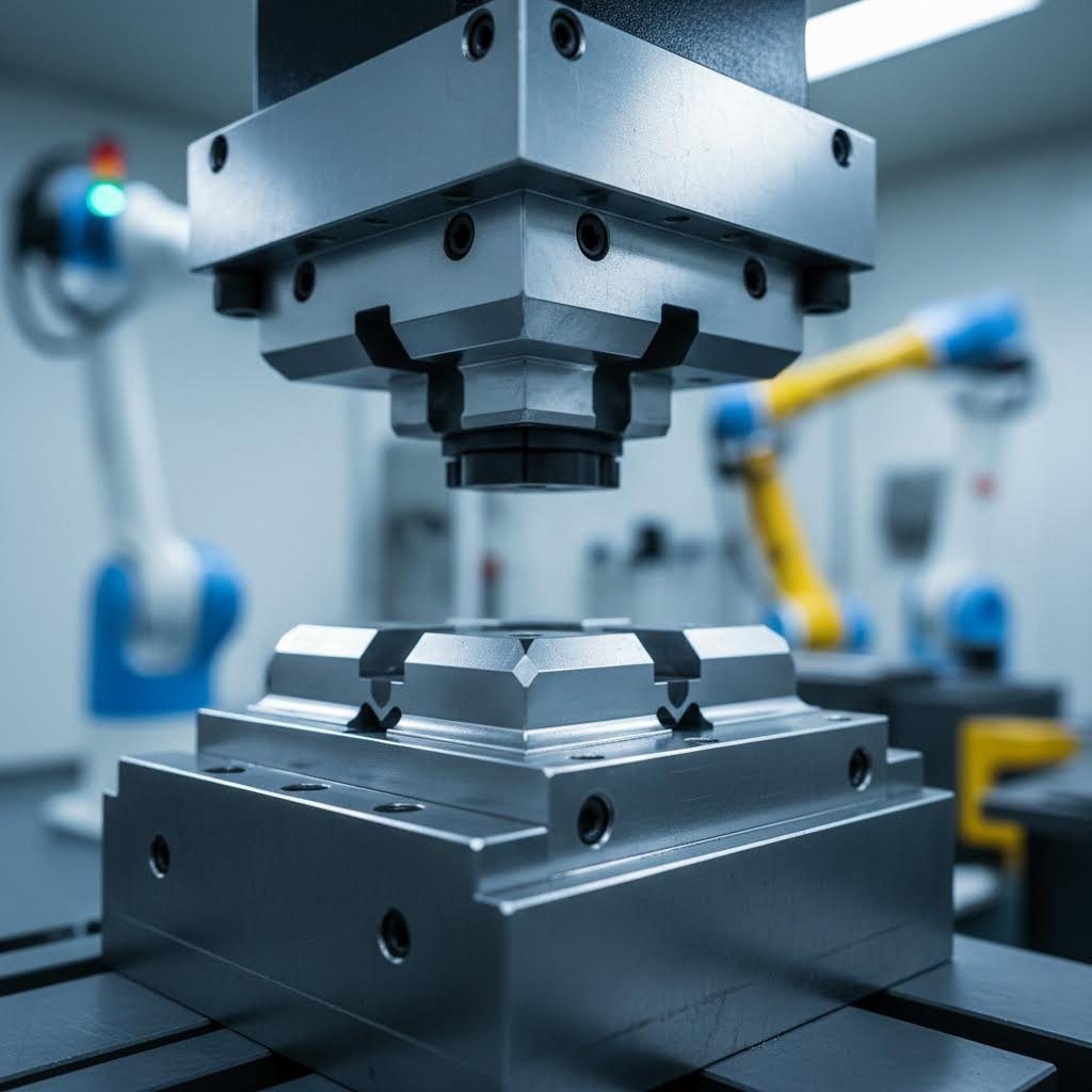
Сіз қашанда-қолдан жазық металл парақтарының автомобиль кузовының панельдеріне, әртүрлі құрылғылардың сыртқы қабықтарына немесе күрделі электрондық қораптарға айналуын ойланған ба? Бұл сұраққа жауап қазіргі заманғы өндірістің орталығында орналасқан дәлдік құралында — пішірме қалыбында жасырылған.
Пішірме қалыбы — бұл жазық металл парақтарын үшөлшемді бөлшектерге айналдыру үшін өндірісте қолданылатын арнайы құрал; ол престік машина арқылы қолданылатын күштің әсерімен жұмыс бетінен материалды алып тастамай, бақыланатын пластикалық деформация арқылы пішін береді.
"Өндірісте қалып деген не?" деген сұраққа жауап іздей отырып, сіз осы құралдардың металлды физикалық түрде пішіндеуге арналған қолдар ретінде қызмет ететінін байқайсыз. Қалып — бұл материалды алдын ала белгіленген қуысқа дәл пішін, өлшем және қажетті сапалық сипаттамаларға ие болу үшін үлкен қысым көрсетуге арналған құрал. Материалды кесіп алу немесе алып тастау процестерінен айырмашылығы — пішірме қалыптары металлдың механикалық қасиеттерін пайдаланады — яғни оның қысым әсерінен созылуы, иілуі және ағу қабілеті.
Пішіндеу матрицасы басқа матрицалардан немен ерекшеленеді
Сонымен, әртүрлі түрдегі матрицалар дегеніміз не? Матрицаларды жиі екі негізгі санатқа бөледі: кесу матрицалары мен пішіндеу матрицалары. Бұл айырманы металл өңдеумен айналысатын әркімнің түсінуі маңызды.
Материалды шығару, кесу немесе бөлу үшін қолданылатын кесу матрицаларына — контур кесу мен тесу матрицалары жатады. Олар пішінді шығарып тастайды немесе тесіктер жасайды, ал жұмыс бетін таза кесу үшін сүйір шеттерге ие болады.
Басқа жағынан, пішіндеу матрицалары мүлде басқа принцип бойынша жұмыс істейді. Олар материалды (сығылу, созылу немесе екеуінің де қосындысы) күш қолдану арқылы деформациялайды және материалдың сынбай-ақ пластикалық деформацияға ұшырау қабілетіне сүйенеді. Сәйкес Wikipedia's manufacturing reference , иіру — матрицамен пішіндеу операциясының классикалық мысалы, ал контур кесу мен тесу — кесу операцияларын көрсетеді.
Бұл негізгі айырмашылық — кесу матрицалары сияқты қалдықтарды түзбейді. Оның орнына, материалды созады, жер-жерінен сығады, ал жазық заготовка соңғы үш өлшемді пішінді қабылдайтын болады.
Әрбір пішіндеу матрицасының негізгі компоненттері
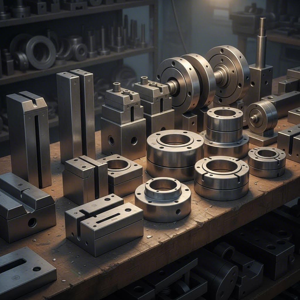
Сіз қарапайым иілу матрицасын немесе күрделі прогрессивті пішіндеу жүйесін тексеріп отырсыз ба — белгілі бір компоненттер тұрақты түрде кездеседі. Бұл матрица компоненттерін түсіну бүкіл матрица құралының біріктірілген жүйе ретінде қалай жұмыс істейтінін түсінуге көмектеседі:
- Пуансон: Материалға басу арқылы созылу, иілу немесе пішіндеу операциясын орындайтын жоғарғы компонент. Ол пішінделген бөлшектің ішкі пішінін анықтайды.
- Матрица блогы: Жұмыс бетін берік бекітетін және пішіндеу операциялары үшін қарама-қарсы бетті қамтамасыз ететін төменгі компонент. Ол дайын бұйымның сыртқы контурларын анықтайды.
- Матрица табаны: Матрицалық жинақты бекітіп, престе орнатуға арналған пластина. Ол конструкциялық қаттылықты қамтамасыз етеді және жоғарғы мен төменгі компоненттердің дәл туралауын қамтамасыз етеді.
- Бағдаршамалар мен втулкалар: Жоғары жылдамдықты операциялар кезінде пуансон мен матрица блогының дәл туралауын сақтайтын дәлдік компоненттері.
- Шайбаларды шығару пластинасы: Әрбір ходтан кейін пуансоннан пішінделген бөлшекті шығарады, материалдың құрал-жабдыққа жабысып қалуын болдырмау үшін.
Пішіндеу матрицалары әдетте білікті құрал-жабдық жасаушылармен жасалады және престе орнатылғаннан кейін өндіріске қосылады. Жұмыс бөлігі соңғы пішінге ие болу үшін әртүрлі құралдар немесе операцияларды қолдана отырып, бірнеше сатылардан өтуі мүмкін — бұл өндірісті жоспарлаудың тиімді болуы үшін осы матрица құралдарының санатын түсінудің маңыздылығын көрсетеді.
Бұл мақала формалық шаблондарды меңгеруге арналған толық құрал болып табылады — теориялық түсінікті практикалық қолданыспен ұштастырады. Сіз қолжетімді әртүрлі шаблон түрлерімен танысасыз, оларды қандай тәсілмен қара темірден жасау керектігін үйренесіз, өнім сапасына әсер ететін материалдық факторларды түсінесіз, сонымен қатар шаблондардың қызмет ету мерзімін ұзартып, бөлшектердің сапасын тұрақты ұстайтын таңдау, орнату және қолдану тәжірибелері туралы ақпарат аласыз.
Формалық шаблондардың түрлері және олардың нақты қолданылу аясы
Енді сіз формалық шаблондардың негізгі компоненттері мен мақсатын түсінгенсіз, сондықтан қазіргі заманғы өндірісте қолданылатын формалық өңдеудің әртүрлі түрлерін қарастырайық. Әрбір санат өзіндік операциялық қажеттіліктерді қанағаттандырады — дұрыс шаблонды таңдау сіздің өндірістік тиімділігіңізге, бөлшектердің сапасына және құрал-саймандарға жұмсалатын инвестицияға тікелей әсер етеді.
Формалық шаблондарды мамандандырылған шеберлер ретінде елестетіңіз. Иілу шаблоны бұрыштар мен жақтарды жасауда жоғары деңгейде қолданылады, ал тарту шаблоны жазық заготовкаларды терең стакандарға немесе қабықтарға айналдырады қолданылуыңызға сәйкес келетін дұрыс құрал-жабдықты таңдау – бұл тек жақсы тәжірибе ғана емес, сонымен қатар тұрақты, жоғары сапалы нәтижелерге жету үшін маңызды шарт.
Иілу мен созу матрицалары туралы
Иілу матрицалары жаппа металдан бұйымдар жасауда ең кең таралған құралдардың бірі болып табылады. Бұл құралдар бұрыштар, желобтар және фланецті шеттер жасау үшін сызықты ось бойынша жергілікті күшті қолданады. Олар L-тәрізді қосалқылардан бастап күрделі автомобиль конструкциялық элементтеріне дейінгі барлығын жасауда қолданылады.
Иілу процесі материалды матрица саңылауының үстіне орналастыру арқылы және пуансонның түсіп, материалды ойыққа итеруі арқылы жүзеге асады. Сыртқы радиустағы материал созылады, ал ішкі радиустағысы сығылады. Сәтті иілу – трещинаның пайда болуын немесе артық серпімділіктің болуын болдырмау үшін осы қарама-қарсы күштерді бақылауға байланысты.
Сызу матрицалары бұрышты иілулерді жасауға негізделген емес, жазық заготовкаларды стакан тәрізді, қорап тәрізді немесе күрделі пішінді бөлшектерге созу арқылы жұмыс істейді. Жазық алюминий дискін сусын банкасының денесіне дейін сығу деп елестетіңіз — бұл терең сызу процесі.
Сызу операциялары кезінде заготовканың матрица ойығына қарай қозғалуын матрица ұстағышы бақылайды, ал пуансон төмен қарай қысым жасайды. Металл пуансон радиусының үстіне созылып, матрицаға қарай ағып келгенде жұқартылады. Терең сызу операциялары бірнеше сатылы кезеңдерді қажет етуі мүмкін, әрбір өтуде бөлшекті тереңдетіп, қабырға қалыңдығын нормативті шектерде сақтайды.
Сәйкес The Phoenix Group , штамп матрицасы кесу, иілу, тесу, рельеф жасау, пішіндеу, сызу, созу, соқтау және экструдерлеу сияқты қосымша құнды операцияларды орындайды — әртүрлі пішіндеу матрицалары өндірістік жүйелерде қалай бірігіп жұмыс істейтінін көрсетеді.
Дәлдік жұмыстар үшін арнайы пішіндеу матрицалары
Қалыптастырудың стандартты иілуі мен созылуынан тыс, бірнеше арнайы қалыптар нақты өндірістік талаптарды қамтамасыз етеді:
Созылатын қалыптау қалыптары материалды шеттерінен ұстап, оны пішін блогының үстіне созады. Бұл әдіс ұшақ фюзеляжының қабығы немесе сәулеттік қаптама сияқты үлкен, жұмсақ қисық панельдерді жасайды. Созылу әрекеті материалды бетінің барлық аймағында серпімді шегінен асырып жалпылама созу арқылы серпімді қайтаруды азайтады.
Тиын соғу қалыптары материалды дәл қуыс пішіндерге кірігу үшін өте жоғары қысымды қолданады. Басқа қалыптау операцияларынан өзгеше, тиын соғу иілудің өзі металлды жай ғана қайта пішіндеумен ғана емес, шынымен орын ауыстыруын қамтиды. Нәтиже? Ерекше дәлдікті допустар мен анық бет бөлшектері. Тиындар, медальдар және дәл электрондық контактілер жиі тиын соғу операцияларын талап етеді.
Рельефті матрицалар материалдың қалыңдығын едәуір өзгертпей, көтеріңкі немесе шұңқыр үлгілер жасау. Декоративті панельдер, идентификациялық табақшалар және мәнерлендірілген беттер бедерлеуге сүйенеді. Пунш мен матрица бір уақытта өңделетін бөлшектің екі жағына да үлгілерді салу үшін бірлесіп жұмыс істейді.
Суық пішіндеу матрицалары жаппа материал емес, қатты металл қорын пішіндеу үшін үлкен күш қолданылатын ом температурасында жұмыс істейтіндіктен ерекше назар аудартады. Бекіткіштер, сақиналар және кішігірім дәлдік бөлшектер жиі сым немесе стержень түрінде болады, оларды суық пішіндеу матрицалары соңғы пішінге айналдырады. Миллиондаған циклдар бойы өлшемдік дәлдікті сақтай отырып, бұл құралдар өте жоғары қысымға шыдай алуы керек.
Валдар түрлендіру матрицаларының материалды роликті станциялар сериясы арқылы біртіндеп пішіндеу арқылы мүлдем өзгеше тәсіл қолданады. Ұзын конструкциялық бөліктер, желобтар және металдан жасалған рама элементтері роликпен пішіндеу желілерінен шығады. Әрбір роликті станция жолақты біртіндеп иіп, соңғы профиль пайда болғанша жұмыс істейді — бәрі жоғары өндірістік жылдамдықпен.
| Қалып түрі | Негізгі операция | Типілік қолданулар | Материалға сәйкестігі |
|---|---|---|---|
| Иілу матрицалары | Сызықтық осьтер бойынша бұрыштар мен фланецтер жасау | Қолаулықтар, каналдар, қорап панельдері, құрылымдық элементтер | Жұмсақ болат, ерімейтін болат, алюминий, мыс-жез |
| Сыйымдылық матрицалары | Жазық дайындамаларды стакан немесе қабықша пішініне созу | Тамақ пісіру ыдыстары, автомобиль отын бактары, сусын банкалары, корпус | Терең тарту болаты, алюминий құймалары, мыс |
| Созылатын қалыптау қалыптары | Үлкен қисықтарды формалық блоктарға созу | Әуе қозғалтқыш қабықтары, автомобиль денесі панельдері, ғимарат панельдері | Алюминий, титан, цирконий |
| Тиын соғу қалыптары | Жоғары қысымды орын ауыстыру дәлме-дәл детальдар үшін | Тиындар, медальдар, электрлық контактілер, дәл компоненттер | Мыс құймалары, қымбат заттар, алюминий |
| Рельефті матрицалар | Көтеріңкі/ойық бет бедерлерін жасау | Безендіру панельдері, атау табелдері, мәнерлендірілген беттер | Жұқа болат, алюминий, мыс-мырыш құймасы |
| Суық пішіндеу матрицалары | Қатты материалдарды бөлшектерді қайта пішіндеу | Бекіткіштер, сақиналар, заклепкалар, дәл механикалық бөлшектер | Көміртегі болат сымы, гильзиялық болат, алюминий стержень |
| Валдар түрлендіру матрицаларының | Тізбектелген валдар арқылы біртіндеп пішіндеу | Құрылымдық бөліктер, су жолақтары, терезе рамалары, металл шпунттар | Цинкпен капталған болат, алюминий, гильзиялық болат орамасы |
Осы әртүрлі пішіндеу түрлерін түсіну өндірістік талаптарға сай құрал-жабдық инвестицияларын сәйкестендіруге көмектеседі. Желілік металдық парақ үшін жоспарланған штамптау матрицасынан гөрі түгелдеу матрицасы мүлдем басқа талаптар қояды. Дәл сондай, жоғары көлемді автомобиль өндірісі бірнеше операцияны біріктіретін прогрессивті пішіндеу матрицаларын оправданады, ал төмен көлемді мамандандырылған жұмыстар үшін қарапайым жеке операциялық құрал-жабдық қажет болуы мүмкін.
Осы классификациялық негіздемені есте ұстай отырып, сіз дәл осы дәлдікті қамтамасыз ететін құралдардың қалай жасалатынын — құрал-жабдық болатының шикі материалдан бастап соңғы жиналғанға дейінгі процесті зерттеуге дайынсыз.
Пішіндеу матрицалары шикі материалдардан қалай жасалады
Миллиондаған циклдан кейін де сақталатын пішіндеу матрицасы мен ерте бұзылатын матрицаның айырмашылығын ең болмаса ойланып көрдіңіз бе? Жауап матрица престе жұмыс істемес бұрын, яғни дәлдік құралдарына айналатын құрал-жабдық болатыны мен оны дайындаудың үнемі бақыланатын процесінен басталады.
Матрица жасау нені білдіретінін түсіну инженерлік біліктілік пен , алдыңғы қатарлы машиналар және қатаң сапа бақылауын қамтитын қызықты саяхат.
Құрал-жабдық болатынан дәлдік құралдарына дейін
Матрица дайындау процесі әрбір кезеңі дәлдікті талап ететін жүйелі тізбектен тұрады. Fremont Cutting Dies матрица жасаушылар құрал-жабдық болаты, көміртегі болаты, ерітінді болаты және басқа да арнайы материалдар сияқты шикізаттарды пайдаланады — олардың әрқайсысы үлкен қысым астында қайталанатын жұмыс режиміне шыдай алу қабілетіне байланысты таңдалады.
Дағдылы матрица жасаушы шикі материалдарды дайын құралға қалай түрлендіреді:
- Жобалау және инженерия: Бұл процесс нақты сызбалар мен CAD модельдерінен басталады. Инженерлер жиі бірнеше дизайн нұсқасы арқылы өтетін дәл сипаттамалар жасау үшін бірлесіп жұмыс істейді. Қазіргі заманғы құрылғы үлгілерін жасау көбінесе CAD/CAM интеграциясына негізделеді, мұнда компьютерлік дизайн тікелей өндірістік жабдыққа беріледі.
- Материалды таңдау: Дұрыс матрицалық болатты таңдау тозуға төзімділіктен бастап серпімділікке дейінгі бәрін анықтайды. Үлкен кернеумен пісіру қолданбалары әдетте D2 немесе M2 сияқты құрал-жабдық болаттарын қажет етеді, олар жоғары қаттылық пен төзімділік ұсынады. Материал өңделетін бөлшектің қасиеттері мен күтілетін өндіріс көлеміне сәйкес келуі тиіс.
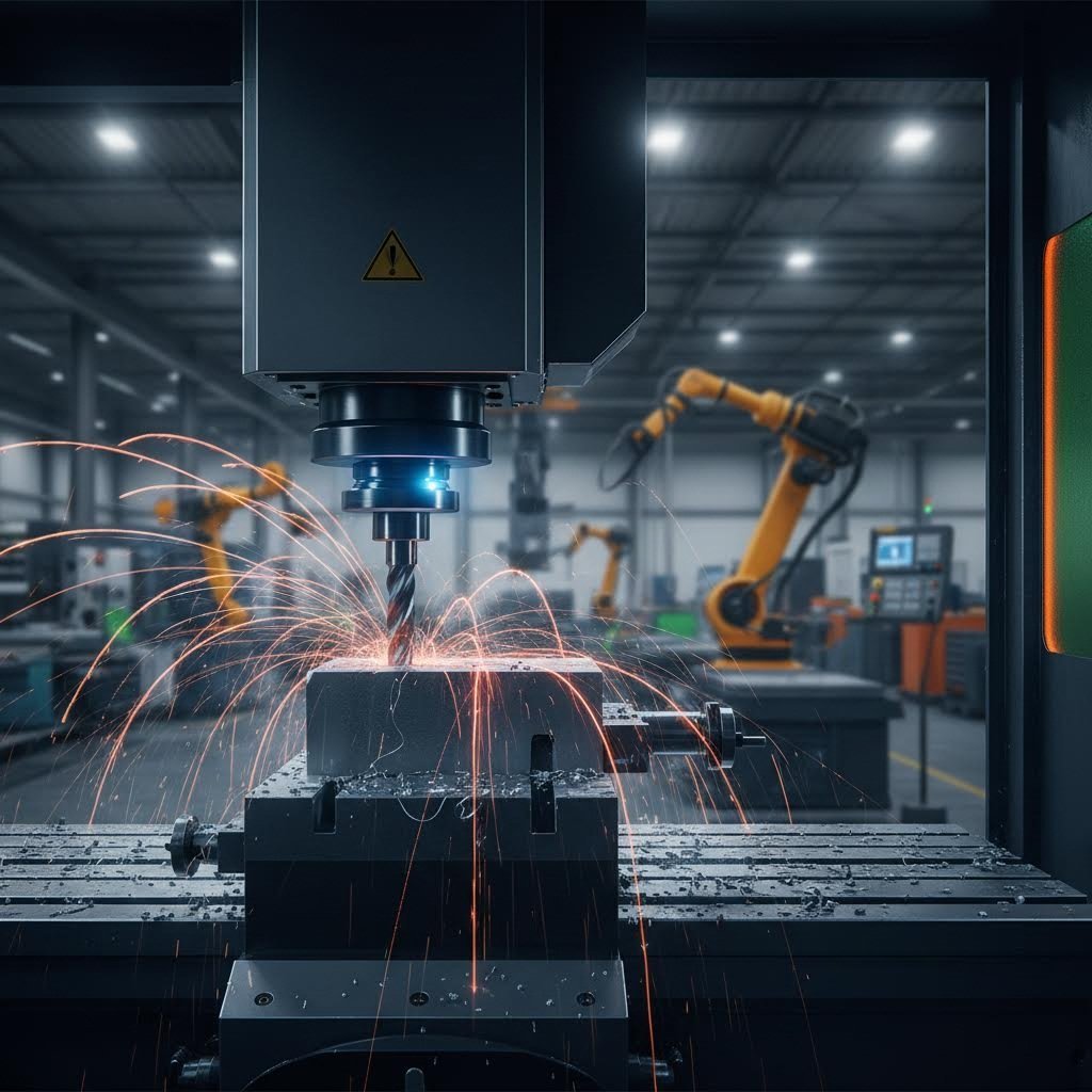
- Алғашқы өңдеу: CNC машиналары негізгі материалдарды алып тастап, негізгі матрица геометриясын жасайды. Бұл кезең дәлдіктен гөрі тиімділіктің алдында маңызды болып табылады — соңғы өңдеу операциялары үшін жеткілікті материал қалдырады. Білікті механиктер соңғы бөлшектегі кернеудің шоғырлануын азайтатын құрал жолдарын бағдарламалайды.
- Ыстырма әдістері: Мүмкін, ең маңызды түрлендіру матрица компоненттері жылулық өңдеу пешіне түскен кезде болады. Бақыталатын қыздыру мен салқындату циклдері болаттың молекулалық құрылымын өзгертеді, бұл қаттылық пен тозуға қарсы төзімділікті айтарлықтай арттырады және қажетті серпінділікті сақтайды.
- Дәлме-дәл ұнтақтау: Жылулық өңдеуден кейін компоненттер соңғы өлшемдерге жету үшін дәлме-дәл әрі ұнтақтауға ұшырайды. Бетін әрі ұнтақтайтын станоктар, цилиндрлік әрі ұнтақтайтын станоктар және арнайы ЭҚК жабдықтары бірге жұмыс істеп, көбінесе мыңнан бір дюйммен өлшенетін дәлдікке жеткізеді.
- Соңғы жинау және орнату: Жеке компоненттер толық матрица жүйесі ретінде бірігеді. Бұл кезең матрицалық тесіктерді, матрицалық блоктарды, бағыттауыш штифтерді және қосалқы компоненттерді дұрыс туралау мен жұмыс істеуін қамтамасыз ету үшін ұқыпты орнатуды қамтиды.
Жылулық өңдеу мен бетінің соңғы өңдеуінің негіздері
Жылулық өңдеу ерекше назар аудартады, себебі ол матрицалық болат қасиеттерін негізінен өзгертеді. Матрицалық бөлшектерді өңдеу кезінде материал салыстырмалы түрде жұмсақ және өңдеуге жеңіл күйінде қалады. Жылулық өңдеу өңделетін бөлшектермен контакті тұсындағы беттерді қатайтады, ал ядро әсер ететін жүктемелерді трескей қалмастан төте шыдайтындай дәрежеде серпімділігін сақтайды.
Бұл процесс әдетте мыналарды қамтиды:
- Аустениттену: Болатты кристалдық құрылымы өзгеретін температураға дейін қыздыру
- Суыту: Қатайған құрылымды сақтау үшін тез суыту
- Темперлеу: Қаттылық пен серпімділікті теңестіру үшін бақыланатын қайтадан қыздыру
Жылулық өңдеуден кейін беттік өңдеу операциялары жүргізіледі. Тозу беттерін циректеу пішіндеу процесі кезінде үйкелісті азайтады және бөлшектердің босаюын жақсартады. Кейбір қолданыстар қиын өндірістік орталарда матрицаның қызмет ету мерзімін одан әрі ұзартатын — титан нитриді немесе алмаз тәрізді көміртегі сияқты — арнайы қаптамаларды талап етеді.
Сапа бақылау нүктелері бұл жол бойынша барлық жерде кездеседі. Barton Tool жалпы тексеру әдістеріне визуалды тексеру, өлшемдік тексерулер және бет беткі қаттылығын өлшеу кіреді. Координаталық өлшеу машиналары (CMM) күрделі геометриялар үшін жоғары дәлдік ұсынады, ал бұйымдардың ішкі ақауларын бұйымдарға зақым келтірмей-ақ анықтайтын бұйымдарды бұзуға болмайтын әдістер қолданылады.
Неге матрицалық болатты таңдау осылшама маңызды? Төменгі сапалы материалдардан жасалған пісіру матрицасы бірнеше мың бөлшек үшін қанағаттанарлықтай жұмыс істеуі мүмкін — содан кейін тез бұзыла бастайды. Сапалы құрал-жабдық болаттарын дұрыс жылумен өңдегеннен кейін, қайта жөндеуді қажет етпес бұрын миллиондаған сапалы бөлшектер шығаруға болады. Сапалы материалдарға алғашқы салым құралдың қызмет ету өмірі бойы табыс әкеледі.
Өндірістің негізгі негіздері қамтылғаннан кейін, әртүрлі жұмыс беті материалдарының пісіру матрицаларыңызбен қалай әрекеттесетінін түсіну келесі маңызды сұрақ болып табылады.
Пісіру матрицасының жұмыс істеуіне әсер ететін материалдық факторлар
Сіз дұрыс матрица түрін таңдап, сапалы өндірісті қамтамасыз еттіңіз — бірақ көптеген металды формалау операциялары осы жерден қиындыққа тап болады. Жұмыс бетінің өзі материалдың формалау матрицасы қалай жұмыс істейтініне, қанша уақытқа шыдайтынына және бөлшектеріңіз геометриялық параметрлерге сай келетін-келмейтініне айтарлықтай әсер етеді.
Мынадай ойланыңыз: жоғары беріктікке ие болатты формалау мүлде басқаша сезіледі. Әрбір материал өзіндік ерекшеліктерімен құрал-жабдықпен ынтымақтастық жасайды немесе оған қарсы шығады. Осы мінез-құлықтарды түсіну кездейсоқ болжауды болжанатын, қайталанатын нәтижеге айналдырады.
Парақты металл формалау процесі материал қасиеттері, матрица геометриясы және қолданылатын күштер арасындағы күрделі өзара әрекеттестікті қамтиды. Бұл факторлар сәйкес келгенде бөлшектер тұрақты түрде рұқсат етілген ауытқулар шеңберінде пайда болады. Ал егер сәйкес келмесе? Сіз ақауларды жоюмен, уақытынан бұрын тозған құрал-жабдықты ауыстырумен және қалдықтар деңгейінің өсуін бақылаумен айналысасыз.
Матрицаны таңдауды анықтайтын негізгі материал қасиеттері
Нақты құймаларға кірмей тұрып, кез келген пісіру операциясы кезінде ең маңызды болып табылатын материалдың қандай сипаттамаларын анықтап алайық:
- Қабылдайтын күші: Тұрақты деформация басталатын кернеу деңгейі. Құрамы жоғары беріктікке ие материалдар үлкен пісіру күштерін және мықтырақ матрица құрылысын қажет етеді.
- Қозғалтын күші: Сынуға дейінгі материал шыдай алатын максималды кернеу. Бұл созу операциялары кезінде материалды қаншалықты агрессивті созуға болатынын анықтайды.
- Созылуы: Сынуға дейін материал қаншалықты созылатыны. Шарт бойынша Auto/Steel Partnership Stamping Design Manual созылу қабілеті беріктіктің артуына қарай төмендейді — яғни, беріктігі жоғары болаттар созылудың төмендеуіне төзеді және жарылуға бейім болады.
- Пластикалық қатайту қарқыны (n-мәні): Деформация кезінде материал қаншалықты тез берік болатыны. n-мәні жоғары материалдар деформацияны біркелкі таратады, осылайша жергілікті жұқаруды азайтады.
- Пластикалық деформация қатынасы (r-мәні): Терең созу мүмкіндігін көрсетеді. r-мәні неғұрлым жоғары болса, стакан түріндегі пісіру операциялары кезінде жұқаруға төзімділік соғұрлым жақсы болады.
- Серпімділік модулі: Пішімдеу күштерін босатқаннан кейін материал қаншалықты серпімді болатынын анықтайтын қаттылық.
Бұл қасиеттер жеке тұрғыдан болмайды. Материалдың химиялық құрамы, өңдеу тарихы және қалыңдығы престе кездесетін мінез-құлықты қалыптастыру үшін бәрі бірге әсер етеді.
Қалып дизайндағы серпімділік компенсациясы
Серпімділік металдарды пішіндеу операцияларындағы ең тұрақты қиыншылықтардың бірі болып табылады. Пішімдеу күштерін босатқан кезде серпімді қалпына келу материалдың бастапқы пішініне қайта оралуына әкеледі. Нәтиже? Бөлшектер қалып геометриясына сәйкес келмейді.
Қағаз қыстырғышты бүгуді және қалың болаттан жасалған сырықты бүгуді елестетіңіз. Қағаз қыстырғыш бүгілген жерінде қалады, ал сырық байқалатындай дәрежеде серпімді болады. Осы принцип барлық жұқа металл пішіндеуге қатысты, оның ауырлығы материал қасиеттеріне байланысты.
Авто/болат серіктестігінің зерттеулері материал беріктігі артқан сайын серпімді иілу проблемасының одан әрі арта түсетінін көрсетеді. Жұмсақ болаттар үшін 3 градусқа асыра иілу, әдетте, серпімді қалпына келуді компенсациялайды. Мақсатты бұрыштарға жету үшін 275-420 МПа диапазонындағы жоғары беріктіктегі болаттар жиі 6 градустан астам асыра иілуді талап етеді.
Серпімді иілудің шамасына әсер ететін бірнеше факторлар бар:
- Иілу радиусы: Кіші радиустар материалды пластикалық деформацияға толықтай енгізу арқылы серпімді иілуді азайтады. Жоғары беріктіктегі материалдар үшін ұстауыш радиустеріне металдың қалыңдығының 1-2 есесін ұсыну қажет.
- Материалдың қалыңдығы: Бірдей материалдан жасалған жұқа қабаттар әдетте қалың бөліктерге қарағанда серпімді иілудің пайыздық көрсеткішінің жоғарырағын көрсетеді.
- Созылуға дейінгі қатынас: Созылу мен ағу беріктігі арасындағы қатынасы жоғары материалдар жиі серпімді иілудің өзгеруін көрсетеді.
- Пішіндеу әдісі: Түбіндегі өлі нүктеге жақын материалды 2% немесе одан да көбірек созатын шығыр процестері серпімді иілуге әкелетін қалдық кернеуді тиімді түрде азайтады.
Форма жасаушылар геометриялық түзету арқылы серпімді оралуға жол бермейді — фланец бұрыштарына асыра иілу енгізеді, пуансон профилін түзетеді және кейде престің жүрісін аяқтауына дейін бақыланатын созылу туындататын соңғы созу операцияларын қамтиды.
Жоғары беріктік пен экзотикалық құймалармен жұмыс істеу
Қазіргі заманғы өндірістік өндіріс барынша жетілдірілген материалдармен жұмыс істеуге арналған пішіндеу формаларын талап етеді. Автокөліктердің жеңілдетілуі, әуежай қажеттіліктері және үй техникасының пайдалылық стандарттары барлығы да күштірек материалдардың жұқа қабаттарына қарай ығысады.
Алюминий қорытпалары: Бұл материалдар көптеген сорттарда өте жақсы пішінделуді қамтамасыз етеді, бірақ өзіндік қиындықтар туғызады. Алюминий болаттан өзгеше қатайиды, басты серпімді оралу көрсетеді және форма беттеріне қатынасқанда шығындалуға бейім болады. Дұрыс майлау және беттік өңдеулер маңызды рөл атқарады. Көптеген алюминийді пішіндеу операциялары материалдың ауысуын және беттік ақауларды болдырмау үшін цехталған немесе қапталған форма беттерін талап етеді.
Қызылтас: Жоғары жұмыс қатайту жылдамдығы шойынның пішіндеу реттілігіне мұқият назар аударуды талап етеді. Бөлшектердің пішін берілгіштігін қалпына келтіру үшін операциялар арасында аннимдеу қажет болуы мүмкін. Қалып саңылаулары әдетте көміртегі болат қолданылуына қарағанда тығыздау болады — серпімді оралу мен жақ бүйірінің иілуін бақылау үшін жиі металдың бір қабат қалыңдығына дейін шектеледі.
Жоғары беріктікті төмен қоспалы (HSLA) болаттар: AutoForm оқу материалдары осындай материалдармен жұмыс істеген кезде ағыс қисықтарын және пішіндеу шегі диаграммаларын түсіну маңыздылығын атап өтеді. 300-550 МПа аралығындағы ағу беріктігіне ие HSLA маркалары жұмсақ болатпен қолданылатын процестерден өзгеше қалыптау процестерін талап етеді. Дәстүрлі тұйық бұрышты тарту операцияларына қарағанда, әдетте формалық қалыптар немесе ашық ұшты тарту қалыптары жақсырақ нәтиже береді.
Екі фазалы және TRIP болаттар: Бұл 600 МПа-дан 1000 МПа-ға дейінгі созылу беріктігіне ие болатын өте жоғары беріктік материалдары өзінің микрояпрысында фазалардың қосылуы арқылы өнімділікті арттырады. Auto/Steel Partnership мәліметі бойынша, екіфазалы болаттар бастапқы пластикалық қатайту деңгейінің жоғары болуынан туындайды, ол оларды формалау мен соңғы беріктікті талап ететін қолданулар үшін қолайлы етеді. Алайда, олардың шектеулі созылуы жарылуға жол бермеу үшін қалып процесін жоспарлауды ұқыпты орындауды талап етеді.
Материал қалыңдығы мен қалып саңылауының өзара байланысы
Материал қалыңдығы формалық қалып дизайндары мен жұмыс істеуінің бірнеше аспектілеріне тікелей әсер етеді. Қалың материалдар үшін керек:
- Үлкен формалау күштері: Престің тоннаждық талабы ұқсас геометриялар үшін қалыңдықпен шамамен пропорционал өседі.
- Түзетілген қалып саңылаулары: Саңылау материал қалыңдығын ескеріп, өлшемдік дәлдікті бақылау үшін пунш пен матрицаның арасында болуы керек. Жоғары беріктікті болаттар үшін кесу операцияларында металдың қалыңдығының 7-10% аралығындағы саңылаулар типтік болып саналады.
- Өзгертілген иілу радиустары: Сыну радиусының минималды спецификациялары трещинаны болдырмау үшін қалыңдықтың еселенуі (1t, 2t және т.б.) ретінде көрсетіледі.
- Қалып қаттылығын арттыру: Жұмыс бетінің қалыңдау нұсқалары қисықты болдырмау үшін қаттылау конструкцияны талап ететін қалып құрылымы арқылы үлкен жүктемелерді береді.
Жұмыс бетінің талаптарына сәйкес қалып материалдарын таңдау
Жұмыс бетінің материалы мен қалып износ арасындағы байланысты мұқият қарастыру қажет. Қаттырақ және берігерек жұмыс бетінің материалдары қалып бетінің нашарлауын жылдамдатады. Абразивті түбір, қиындалған шеттер және жоғары контактілі қысымдар құрал-жабдықтың нашарлауына үлес қосады.
Беріктігі жоғары болаттармен ұзақтықтағы өндіріс жұмыстары үшін:
- Износқа төзімділігі арттырылған жоғарғы сортты құралдық болаттарды көрсетіңіз
- Хромдау немесе иондық нитрлеу сияқты беттік өңдеуді қарастырыңыз
- Компрессиялық нүктелерде ілеспеуді болдырмау үшін қаттылатқан болаттан жасалған байлайтын беттерді пайдаланыңыз
- Жүктеме астында қалып арақашықтығын тұрақты сақтау үшін қаттылатқан теңестіру блоктарын пайдаланыңыз
Жоғары беріктік материалдары үшін прототип құрал-снарядтары мырыш қорытпалары сияқты жұмсақ материалдардан аулақ болу керек. Талап етілетін жұмыс беті материалдарымен алғашқы сынақтардың өзі қалыптастыру мінез-құлық туралы мағыналы деректер алу үшін кем дегенде қазан сымының болаты сияқты қатты қалып құрылымынан пайда келтіреді.
Осы материалдарға қойылатын талаптарды түсіну сізді қалыптау қалыптарының сәттілігінің келесі маңызды аспектісіне — дәлдік талаптары мен допусстар стандартына — негізделген шешімдер қабылдауға дайындайды.
Қалыптау қалыптары үшін дәлдік талаптары мен допусстар стандарты
Сіз дұрыс материалды таңдадыңыз және қалыптау процесін жобаладыңыз — бірақ сіздің құрал-снаряд қалыптарыңыз нақты қандай дәлдікте орындалуы керек? Бұл сұрақ өлшемдік ауытқулар, бас тартылған бөлшектер мен қанағаттанбаған тұтынушылармен шаршаған өндірістік серияларды сапасы тұрақты болатын өндірістен ажыратады.
Пішін құрал-снарядтеріндегі дәлдік барлық жерде мүмкіндігінше төмен шектеулерге жету туралы емес. Бұл қай өлшемдердің ең маңызды екенін түсіну және оларды штамптау матрицалары қызмет көрсету мерзімі бойынша қабылданатын бөлшектер шығаратындай етіп, спецификациялар аясында бақылау туралы.
Пішіндеу матрицасының дизайнындағы маңызды шектеулер
Әрбір пішіндеу матрицасы соңғы бөлшектің сапасына тікелей әсер ететін өлшемдерді қамтиды — ал басқаларында еркін шектеулер функционалдық мәселелер туғызбайды. Дизайн процесінің басында осы маңызды элементтерді анықтау артық инженериялануды (ақша шығыны) және жеткіліксіз инженериялануды (қалдық өндіруді) болдырмауға көмектеседі.
Құрал-снаряд дәлдігі мен бөлшек дәлдігі арасындағы байланыс қарапайым принципке бағынады: сіздің бөлшектеріңіз сіздің құрал-снарядыңыздан гөрі дәлірек бола алмайды. Егер пішіндеу элементін ұстайтын матрица пластина номиналдан 0,1 мм ауытқыса, бұл қате әрбір шығарылған бөлшекке тікелей беріледі. Прогрессивті матрицаның бірнеше станциялары үшін осыны көбейтіңіз және шектеулердің жиналуы маңызды мәселе болып табылады.
Төмендеу шегі бірнеше операциялар бойына жеке өлшемдік ауытқулар жиналған кезде пайда болады. Бес формалау станциясы бар прогрессивті матрицаны қарастырыңыз. Әрбір станция өз орындалу шегін, саңылау өзгерісін және туралау ауытқуын қосады. Соңғы станцияға дейін бұл кіші қателер жиналады — соның нәтижесінде дайын бөлшектер техникалық шарттан тыс қалуы мүмкін.
Сәйкес Adient's North American Die Standards , барлық тесік диаметрлері номиналды мән мен шақтаманың жоғарғы шегі арасында болуы керек. ±0,05 мм дәлдіктегі шақтамалар үшін құралдар номинал бойынша жасалуы керек — өндіру кезінде ауытқуға мүлдем орын қалдырмай.
Туралау және саңылау сипаттамалары
Жоғарғы және төменгі матрица компоненттерінің дұрыс туралануы сіздің металл штампыңыздың тұрақты жұмыс істеуіне немесе тұрақсыз нәтижелер беруіне әсер етеді. Бағыттауыш пиндері мен втулкалар миллиондаған престік циклдар бойы бұл маңызды қатынасты сақтайды.
MISUMI техникалық нұсқауында матрица мен пуансон арасындағы саңылау — кесу немесе пішіндеу қырларының арасындағы қашықтық — бөлшектің сапасы мен құрал-жабдықтың қызмет ету мерзіміне тікелей әсер ететіні айтылады. Стандартты ұсыныстар жалпы қолданыс үшін материал қалыңдығының әр жағына 10% шамасын ұсынады, алайда заманауи даму бағыты 11-20% саңылау құрал-жабдықтағы кернеуді азайта отырып, жұмыс істеу мерзімін ұзарта алатынын көрсетеді.
Негізгі туралау сипаттамалары мыналарды қамтиды:
- Бағдарлау штифтының енгізуі: Кез келген кесу немесе пішіндеу басталмас бұрын бағдарлау манжеті мен тіреуіш арасындағы контакт ұзындығы ең аз 40 мм болуы керек
- Престің пластинасының параллельдігі: Жоғарғы және төменгі матрица табандары жүктеменің теңсіз болуын болдырмау үшін әрбір 100 мм-ге 0,02 мм шамасында параллель беттерді сақтауы керек
- Итеру блогының саңылаулары: Шамамен 0,1 мм саңылау итеру блоктары латеральды күштерді бекітіп, бұғатталуға жол бермейді
- Матрица табанының жазықтығы: Жұмыс аймақтарында жазықтық допусы әдетте 0,01-0,02 мм аралығында болатын беттерді цехта өңдеу
| Жұмыс түрі | Стандарттық дәлдік | Өңдеу сипаттамасы | Автокөлік/Әуежай деңгейі |
|---|---|---|---|
| Иілу бұрыштары | ±1.0° | ±0.5° | ±0.25° |
| Тесік орны (нақты орын) | ±0,25мм | ±0.10мм | ±0.05мм |
| Пішінделген элемент биіктігі | ±0,15 мм | ±0,08 мм | ±0.05мм |
| Шетінен тесікке дейінгі арақашықтық | ±0,20 мм | ±0.10мм | ±0.05мм |
| Бетінің профилі | ±0,50 мм | ±0,25мм | ±0.10мм |
| Пунштің матрицаға саңылауы | жағына 10-12% | жағына 8-10% | жағына 5-8% |
Салаға тән дәлдік талаптары
Көптеген салалардағы дәлдік шектері әртүрлі болады — және осы айырмашылықтарды түсіну сізге құрал-жабдықты дұрыс көрсетуге көмектеседі.
Автокөлік қолданбалары: Жабдықтаушыларға арналған техникалық талаптар, әдетте, маңызды сипаттамалар бойынша Cpk мәндерінің 1,67 немесе одан жоғары болуын талап етеді. Adient стандарттарына сәйкес, құрылғыны растау алдында кемінде 30 бөлшектен тұратын қабілеттілік зерттеуі осы статистикалық процестің қабілеттілігін көрсетуі тиіс. Қауіпсіздікке немесе жинақталу дәлдігіне әсер ететін элементтерге ең қатаң бақылау жасалады, ал декоративтік беттерге кеңірек допусстар рұқсат етілуі мүмкін.
Жалпы жасалымдар: Сауда мақсаттағы штамптау операциялары жиі ±0,25 мм орын ауыстыру допусстары мен ±1° бұрыштық допусстармен жұмыс істейді — бұл дәлме-дәл құрал-жабдықтардың қосымша құнын төлемей-ақ, көптеген құрылымдық және функционалдық қолданыстар үшін жеткілікті.
Өндіріс көлемін ескеру: Жоғары көлемдер бір бөлшекке шаққандағы дәлме-дәл құрал-жабдықтардың құны көбірек бірліктерге бөлінетіндіктен, бастапқы допусстардың тарылуын оправдайды. Төмен көлемді мамандандырылған жұмыстар бастапқыда кеңірек допусстарды қабылдай алады, ал шаблондарға дәлдеу үшін реттеу мүмкіндіктері енгізіледі.
Adient стандарттары тесік тікелей тесілмеген жағдайда және 1,0 мм немесе одан аз шамадағы нақты орын допусы керек болған кезде камдық операциялар міндетті болатынын көрсетеді. Дәл сол сияқты, матрица жазықтығынан тыс 0,75 мм немесе одан да кіші допусы бар бет профилдері камдық қайта соғуды талап етеді — бұл дәлдік талаптарының құрал-жабдық күрделілігін қалай анықтайтынын көрсетеді.
Допустар негізі белгіленгеннен кейін, дизайн мақсатын өндірістік шындыққа айналдыру үшін матрицаларды дұрыс орнату мен туралау процедуралары өте маңызды болып табылады.
Пішіндеу матрицаларын орнату және жиі кездесетін ақауларды болдырмау
Сіз сапалы құрал-жабдыққа инвестиция салдыңыз және материалдардың сипаттамаларын түсінесіз — бірақ егер матрицалық престі орнату дұрыс орындалмаса, бұлардың ешқайсысы маңызды болмайды. Пішіндеу матрицалары мен престік жабдықтар арасындағы қарым-қатынас сіздің алғашқы бөлшектеріңіз талаптарға сай бола ма, әлде өндіріс алаңыңыз проблемаларды шешу жаттығуына айнала ма соны анықтайды.
Матрицаны дұрыс орнату теориялық дәлдікті практикалық шындыққа айналдырады. Henli Machinery-ның толық нұсқауы бойынша , қауіпсіз және дәл орнату барлық қадамдық операциялардың негізі болып табылады. Мұнда қадамдарды өткізіп жіберсеңіз, бөлшектердің қабылданбауы, ерте тозуы және операторлардың ренжіуі арқылы төлейсіз.
Қалыпты орнату мен туралаудың қадамдық нұсқаулығы
Престеу операцияларыңызды бастамас бұрын, жүйелі дайындық сіздің өндіріс кезеңіңіз бойынша тұрақты нәтижелерге әкеледі. Бұл процесті жазықтап өту проблемаларға әкеледі және өндіріс кезеңіңізде күрделенеді.
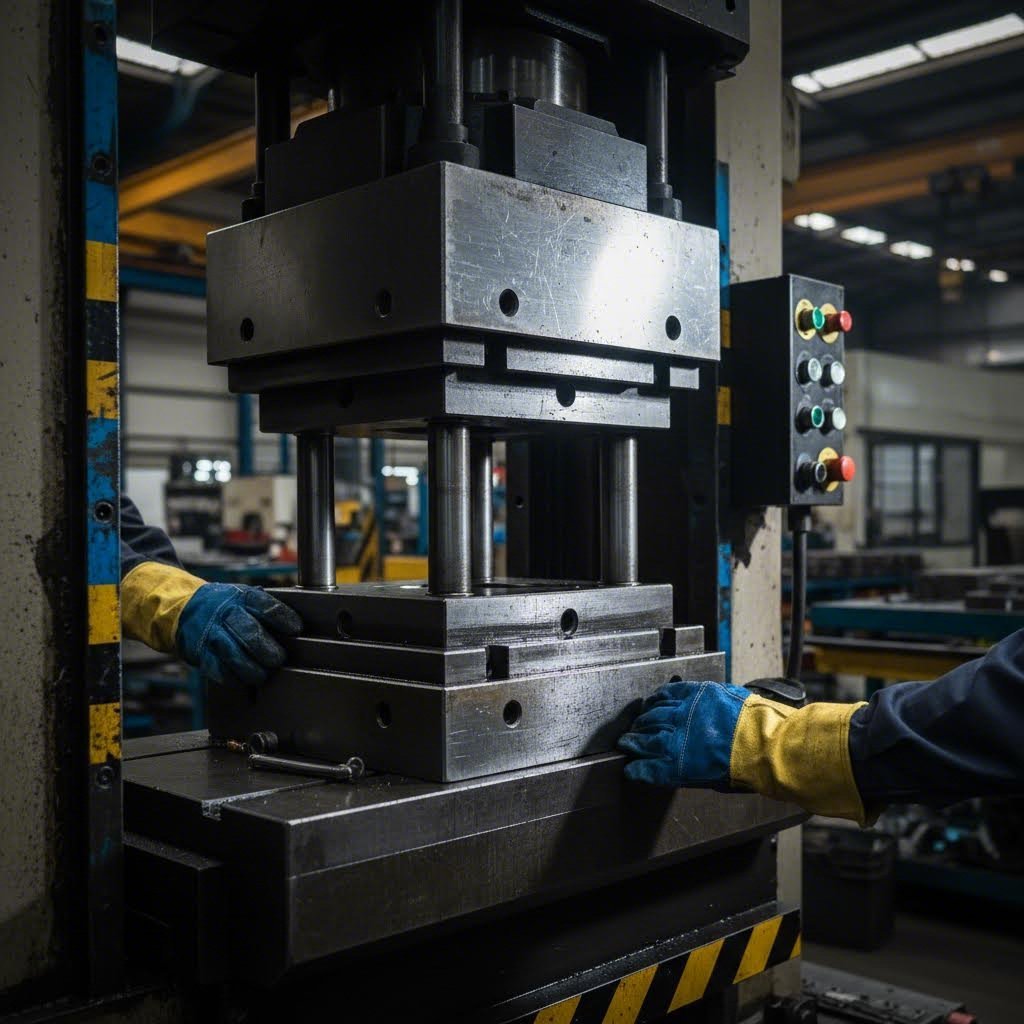
Престі таңдау және дайындау: Алдымен престік құралды қалыптың талаптарына сәйкестендіріңіз. Престің тоннаждық сыйымдылығы есептелген пішіндеу күшін 20-30% қауіпсіздік шегінде асып түсетінін тексеріңіз. Қалып биіктігі престік машинасының биіктік сыйымдылығы диапазонында орналасқанына көз жеткізіңіз. Содан кейін жоғарғы және төменгі престік беттерді мұқият тазартып, туралауды бұзуы немесе дәл өңделген беттерге зақым келтіруі мүмкін ластануларды алып тастаңыз.
Қалыпты орнату реті: Орнатар алдында төменгі матрицаның табан бетін тазалаңыз. Күштің біркелкі таралуы үшін пішіндеуші матрицаны престің столының ортасына орналастырыңыз. Бұл орталандыру материалдың жабысу қаупін және матрица тозуын тездететін біркелкі емес жүктемені азайтады.
Бағыттасуын тексеру: Матрицаларды орнату үшін шөмілмелі режимге престің жүрісін орнатыңыз. Слайдерді ең төменгі өлі нүктеге ұқыпты түсіріңіз. Тұмсықтары бар престік операциялар үшін матрица жиынтықтары үшін тұмсық пен тұмсық саңылауы арасындағы дәл туралау мүлдем маңызды — мұндағы дұрыс емес туралау бағыттаушы элементтердің жабысуына және тез тозуына әкеп соғады.
-
Орнатудан бұрын тексеру нүктелері:
- Престің тонналығының матрица талаптарына сәйкес келетінін тексеріңіз
- Жабылу биіктігінің үйлесімділігін растаңыз
- Барлық үйлесетін беттерді толығымен тазалаңыз
- Туралау штифтері мен втулкаларын тозуға тексеріңіз
- Қалдықтардың шығу тесіктерін кедергілерге тексеріңіз
-
Туралауды тексеру нүктелері:
- Бекітуден бұрын матрицаны престің столының ортасына орналастырыңыз
- Бастапқы жақындау үшін инчинг режимін қолданыңыз
- Төменгі өлі нүктеде сақина мен тесіктің дәл келуін растаңыз
- Қашықтық блоктарының жазық және дұрыс орнатылғанына көз жеткізіңіз
- Пісіру басталмас бұрын ең аз 40 мм бағыттауыш манжеттің енгізілуіне көз жеткізіңіз
-
Соңғы дайындық тексерістері:
- Пісіруге болатын қалыптар үшін алдымен жоғарғы қалыпты бекітіңіз
- Өндірістегі қалыңдықтағы сынақ материалдарын енгізіңіз
- Төменгі қалыпты бекітпес бұрын 2-3 бос жүрісті орындаңыз
- Жүктеме астындағы күштердің біркелкі таралуын тексеріңіз
Ерекше ескертпелер: Сақиналары жоқ қалыптар тек дұрыс орналасуды талап етеді, бірақ қашықтық блоктарының дәл келуіне ерекше назар аударыңыз. Осы сүйеніш компоненттердегі кез келген дұрыс еместіктер күштердің таралуына теріс әсер етеді және қалыптың беріктігі мен бөлшектің сапасына қауіп төндіреді. V-тәрізді қалыптар үшін екі жартысын да бекіткеннен кейін ползунды материал қалыңдығына шамалы көтеріңіз, бұл дұрыс пісіру саңылауын қамтамасыз етеді.
Жиі кездесетін пішіндеу ақауларын жою
Мұқият дайындалғанына қарамастан, пішіндеу процестері кейде ақаулар туғызуы мүмкін. Ақаулар мен олардың себептері арасындағы байланысты түсіну реагирлеу проблемасын жүйелі шешімге айналдырады.
Сәйкес Жиликс-тің техникалық талдауы , шөгу арқылы пішінделген бөлшектегі әрбір ақау пішіндеу «билеуіндегі» қате — матрица немесе пуансон геометриясындағы қате немесе құрғақша ұстағыш күшін дұрыс бағалауға болмайды. Бұл ақауларды диагностикалық хабарлама ретінде оқуды үйрену шешімдерге дейінгі жолыңызды жылдамдатады.
-
Қатпарлар:
- Себебі: артық материал ағынына мүмкіндік беретін құрғақша ұстағыш күшінің жеткіліксіздігі
- Себебі: салыстырмалы тартылуға жеткіліксіз кедергі
- Шешімі: құрғақша ұстағыш қысымын біртіндеп арттыру; тартылу шоқтарын қосу немесе тереңдету
-
Жарылу/Сыну:
- Себебі: материал ағынын шектеуге әкелетін артық құрғақша ұстағыш күші
- Себебі: кернеудің шоғырлануын тудыратын өте кішкентай матрица енгізу радиусы
- Себебі: үйкелістің жоғары болатын аймақтарында майлаудың жеткіліксіздігі
- Шешім: Қыстаушы қысымын төмендету; матрица радиустарын үлкейту (материал қалыңдығының 4-8 есе); майлау жабынын жақсарту
-
Серпімді иілу/Өлшемдік ауытқу:
- Себебі: Материал қасиеттеріне тән серпімді қалпына келу
- Себебі: Матрица геометриясындағы жеткіліксіз асыра иілу компенсациясы
- Шешім: Асыра иілу бұрышын арттыру; штоктың төменгі жағында клеймдеуді қарастыру; созылудан кейінгі операцияларды енгізу
-
Бетінің сызықтары/Жабысуы:
- Себебі: Жеткіліксіз майлама немесе дұрыс емес майлағышты таңдау
- Себебі: Матрица мен өңделетін бөлшек арасында қалдықтардың болуы
- Себебі: Тозып қажыған немесе зақымданған матрица беттері
- Шешім: Майлама жүйесін қайта қарау; тазалау протоколдарын енгізу; матрица беттерін цехтау немесе қайта қаптау
-
Қалыңдығы біркелкі емес қабырға:
- Себебі: созу кезінде материал ағынының біркелкі болмауы
- Себебі: матрицаның орны ауысып кетуі, симметриялы емес пішіндеу күштерін туғызады
- Шешімі: тарту жолағының орнын реттеңіз; матрицаның орнын тексеріңіз; тозған бағыттауыш компоненттерді тексеріңіз
Сынақ жүргізу процедуралары: Тәжірибелік фазаны ешқашан өткізіп жібермеңіз. Өндірістегі қалыңдықтағы өндірістік материалдан кіші партиямен бастаңыз. Тираждық өндіріске кіріспес бұрын бірінші үлгі бөлшектердің маңызды өлшемдерін өлшеңіз. Егер түзетулер қажет болса, өзгерістерді біртіндеп енгізіңіз — шағын ұстағыш күшін реттеу жиі драматикалық өзгерістердің тек қиындататын мәселелерін шешеді.
Престің тоннаждығы мен жабылу биіктігі: Пресс тоннажды жеткіліксіз болса, пішіндеу толық орындалмайды және бөлшектер біркелкі болмайды. Тоннаждың артық болуы матрицаның зақымдануы мен тез тозуына қаупін тудырады. Нақты күштің есептелген мәнге сәйкестігін тексеру үшін алғашқы жұмыс істеу кезінде престің жүктеме көрсеткіштерін бақылаңыз. Жабық орны - престің төменгі өлі нүктесіндегі төсек пен жүргізгіш арасындағы арақашықтық - сіздің матрица жинағыңызға лайықталуы керек және материалдың қалыңдығы үшін жеткілікті тазалықты қамтамасыз етуі керек.
Бұл пісіру процестерін жүйелі түрде орындау арқылы сіз үздіксіз өндірістің негізін қалайсыз. Бірақ баптау – бұл бастама ғана; дәлдікті уақыт өте келе сақтау матрица күйі мен тозу үлгілеріне мақсатты назар аударуды талап етеді.
Пішіндеу матрицаларын ең ұзақ қызмет ету мерзімі мен жоғары өнімділікпен сақтау
Сіздің пісіру матрицасыңыз орнату және бастапқы өндіріс кезінде мүлтіксіз жұмыс істеді, бірақ миллиондаған циклдар бойы оның ең жоғарғы жұмыс өнімділігін қалай сақтауға болады? Дәл осы жерде көптеген операциялар табысқа жетпейді. Техникалық қызмет көрсетуді елемеу жоспарланбаған тоқтап қалуға, қалдықтар мөлшерінің артуына, өндіріс шығындарының көтерілуіне және құралдардың қызмет ету мерзімінің қысқаруына әкеледі, оған сәйкес Apex Tool-дың матрица техникалық қызметі туралы зерттеуі .
Матрицаны техникалық қызмет көрсетуіңізді дәл нақты құрылғыны тамақтандыру секілді қараңыз. Регулярлы тексерістер катастрофалық сынуларға айналмас бұрын кішігірім мәселелерді уақтылы анықтайды. Қатты техникалық қызмет көрсету жоспары уақыт пен ақшаны үнемдейді және матрицаның қызмет ету мерзімі бойы бөлшектердің сапасының тұрақтылығын қамтамасыз етеді.
Қалып қызметін ұзартатын алдын ала сақтандыру жоспарлары
Алдын ала техникалық қызмет көрсетудің жиілігі пайдалану интенсивтілігі мен өндірістік талаптарға байланысты. Жоғары көлемді операцияларға әдетте күнделікті визуалды тексерулер қажет, ал толық техникалық қызмет цикл санауына байланысты апталық немесе айлық болуы мүмкін. Сәйкесінше саланың техникалық қызмет көрсету стандарттары , критикалық компоненттер күнтізбелік интервалдардан гөрі белгілі бір жүріс санынан кейін назар аудартуы мүмкін.
Матрицалық құралдарды дұрыс пайдалану үшін регулярлы тексеру, тазалау және майлау негіз болып табылады. Сіздің техникалық қызмет көрсету тізіміңізге мыналар енгізілуі тиіс:
-
Күнделікті визуалды тексеру:
- Жұмыс беттерінде тозу белгілері, сызықтар немесе басқа зақымданулар бар-жоғын тексеріңіз
- Бағыттауыш штифтер мен втулкалар еркін қозғалатынын, артық люфтін жоқтығын тексеріңіз
- Қиғыш қырларда шатақтар немесе басқа зақымданулар бар-жоғын тексеріңіз
- Майлардың дұрыс деңгейі мен таралуын растаңыз
-
Аптасына бір рет орындалатын техникалық қызмет көрсету жұмыстары:
- Қалдықтар мен металл бөлшектерді тазалап, матрицаның барлық беттерін толық тазалаңыз
- Қозғалыстағы бөлшектер мен тозу беттеріне таза май жағыңыз
- Негізгі спецификацияларға сәйкес критикалық өлшемдерді өлшеңіз
- Die табанының орнатылуын және бекіткіштердің айналу моментін тексеріңіз
-
Айлық толық қайта қарау:
- Дәлдік өлшеуіштерін қолданып, өлшемдік тексеруді жүргізіңіз
- Серіппелердің шаршағыштығы мен дұрыс керілуін тексеріңіз
- Соққылаушы мен die компоненттерінің салыстырылуын растаңыз
- Трендті талдау үшін тозу үлгілерін құжаттаңыз
Егер машина die-лерінде кесінділер, ақаулар немесе ерекше дыбыстар пайда болса, оларды дер кезінде шешіңіз. Осы ескертетін белгілерді елемеу мәселелерді экспоненциалды түрде күрт көбейтеді. Регулярлық техникалық қызмет көрсетуге жұмсалған аз ғана инвестиция die-лердің қызмет ету мерзімін ұзарту мен өндіріс сапасының тұрақтылығы арқылы тиісті пайданы әкеледі.
Die жабдықтарыңызға назар аудару қажеттілігін көрсететін ескертетін белгілер
Сталь die-лерді диагностикалық құрал ретінде оқуды үйрену техникалық қызмет көрсету жауабын жылдамдатады. Осы көрсеткіштерге назар аударыңыз:
- Бөлшек сапасының нашарлауы: Пішінделген жиектерде шыққан бүрлер, рұқсат етілген ауытқудан тыс өлшемдік дрейф немесе бетінің сапасының төмендеуі
- Жұмыс режиміндегі өзгерістер: Пішіндеу циклдары кезінде дабылдың күшеюі, қалыпты емес тербеліс немесе престің жүрісі кезіндегі бұғатталу
- Көзбен көрінетін тозу белгілері: Жұмыс беттеріндегі жылтыратылған тозу іздері, пішіндеу аймақтарындағы көрінетін сызықтар немесе пуансоның бетінде материалдың жиналуы
- Бөлшектердің шаршауы: Серіппелердің серпімділігін жоғалтуы, бағыттауыш бушингтерде артық саңылау пайда болуы немесе бекітпе элементтерінің тұрақты шығуы
Пішіндеу матрицаларын қашан жөндеу керек және қашан ауыстыру керек
Матрицаны жөндеу немесе ауыстыру туралы шешім жалпы иелік құныңызға үлкен әсер етеді. Өндірістегі көптеген матрицаларды алмастырудың тек үлесіне тең шығынға ие болып, дұрыс жөндеу арқылы жаңа сияқты күйге келтіруге болады.
Жөндеу әдетте мыналарды қамтиды:
- Жүндету: Дәлдікті қалпына келтіру үшін кесу жетектерін ұнтақтау. Ысырапты болдырмау үшін бір өтуде 0,001-ден 0,002 дюймге дейін ғана алып тастаңыз. Жалпы есепте 0,005-тен 0,010 дюймге дейін алып тастау арқылы сүйірленгенге дейін қайталаңыз.
- Жылтырлау: Үйкелісті азайту және бөлшектерді шығаруды жақсарту үшін пішіндеу аймақтарындағы бетін өңдеуді қалпына келтіру. Сондай-ақ, өңделген беттер сызықтар мен материалдардың жабысуына төзімді болады.
- Компоненттің ауыстырылуы: Тозып кеткен серіппелерді, бағыттауыш штифттерді, втулкаларды және басқа да ауыстырылатын бөлшектерді ауыстыру. Сапалы матрица жабдықтары осы компоненттердің бастапқы техникалық сипаттамаларына сәйкес келуін қамтамасыз етеді.
- Беттік әдістер: Тозуға төзімділікті қалпына келтіру және келесі жөндеу аралықтарын ұзарту үшін нитрлеу, хромдық қаптау немесе арнайы қаптамаларды қолдану.
Сәйкес GMA-ның жөндеу талдауы , жөндеу уақыты зақымданудың ауырлығына байланысты — минорлық мәселелер үшін үш күннен бастап, кең көлемді каналдық зақымдану жағдайында бір айға дейінгі уақытты қажет етуі мүмкін. Алайда, уақыт — көрінбейтін өндірістік шығын. Мәселелерді тез шешу жиі өндірістегі шығындарды ұзақ уақыт төлеп отырудан арзан тұрады.
Мыналарды ескеріңіз:
- Жаңарту шығындары жаңа матрицаға инвестицияның 50-60%-ын асып түскенде ауыстыруды қарастырыңыз
- Критикалық өлшемдер қайта өңдеуге келмейтін шектен тыс тозып кеткен
- Негізгі материалдарда жорғалау немесе құрылымдық бүліну белгілері бар
- Конструкцияны өзгерту бар болған матрицаны ескірген деп танытады
Ақылды операциялар маңызды өндірістік циклдар үшін артық матрицаларды сақтап отырады. Жөндеу күтілгенше ұзаққа созылса да, өндіріс үзіліссіз жалғаса береді. Бұл тәсіл техникалық қызмет көрсетуді реагирлеуден активті мүлікті басқаруға айналдырады.
Жүйелі техникалық қызмет көрсету тәсілдерін енгізу арқылы пішіндеу матрицалары ұзартылған жұмыс өмірі бойы тұрақты сапа көрсетеді — нақты өндірістік қолданыстар үшін матрица таңдау туралы дұрыс шешім қабылдауға негіз қалайды.
Өндірістік қажеттіліктеріңізге сәйкес пішіндеу матрицасын таңдау
Сіз матрицалардың түрлерін, өндіру процестерін, материалдарға қойылатын талаптар мен жөндеу тәжірибесін түсінесіз — бірақ нақты сатып алу шешімімен кездескенде осы білімдерді қалай біріктіресіз? Нақты қолданылуыңызға сәйкес дұрыс жұқа металл матрицасын таңдау үшін бірнеше факторларды бір уақытта тепе-теңдікте ұстау қажет: материал сипаттамалары, бөлшектің геометриясы, өндіріс көлемі және бюджеттік шектеулер.
Матрицаны таңдауды жұмысқа дұрыс құрал таңдау деп ойлаңыз. Дәлме-дәл хирургтың скальпелі мен токарьдың балтағы екеуі де кеседі — бірақ тапсырмаңызға дұрыс емес құралды пайдалану катастрофалы нәтижелерге әкеледі. Осы принцип метал формалау матрицаларына да қолданылады. Құрал-жабдық инвестицияларын нақты өндіріс талаптарымен сәйкестендіру пайдалы операцияларды құрал-жабдық шығындары мен сапа мәселелеріне батып кеткендерден ажыратады.
Өндіріс талаптарыңызға сәйкес матрицаны таңдау
Әрбір пішіндеу матрицасын таңдау шешімін үш негізгі фактор анықтайды: сіздің жұмыс бөлшегінің материалы, бөлшектің геометриялық күрделілігі және болжанатын өндіріс көлемі. Jeelix-тің толық таңдау нұсқаулығы бойынша, бұл «Шешім Үшбұрышы» таңдау процесін бағыттау үшін дәлелденген нысанды құрады.
Материалдың қалыңдығына қатысты ескертпелер: Жұқа материалдар құрылымы берік матрица құрылымын және престің жоғары тоннажды талап етеді. 0,5 мм алюминий үшін құрылған саңылаулы металл матрицалары 3 мм жоғары беріктіктегі болатты өңдейтін матрицалардан мүлдем өзгеше жұмыс істейді. Сіздің өндірістік құрал-жабдығыңыз материал маркасы ғана емес, сонымен қатар оның нақты қалыңдық диапазонын да ескеруі тиіс.
1 мм-ден төменгі материалдар үшін бір операциялық матрицалар жеткілікті бақылауды қамтамасыз ете ме немесе прогрессивті конфигурациялар жұқа қалыңдықты басқаруды жақсырақ қамтамасыз ете ме соны қарастырыңыз. Жұқа материалдар үшін жұмыс бөлшегі өзі пішіндеу кезінде құрылымдық тұрақтылықты қамтамасыз ететіндіктен, жиі қарапайым матрица конструкцияларын қолдану тиімді болып табылады.
Бүгу радиусы талаптары: Ең аз иілу радиусының техникалық сипаттамалары тікелей матрица геометриясына әсер етеді. Тар радиустар шектерін нақты бақыланатын жиектің пішінімен дәл өңделген соққыштарды талап етеді. Жұмсақ болат үшін ең аз иілу радиусы материал қалыңдығына тең болады — бұл ереже, трещинаның пайда болуын болдырмау үшін кейде 2-3 есе қалыңдықты талап ететін, жоғары беріктікті материалдар үшін әлдеқайда қатаңдайды.
Сіздің конструкцияңыз материал қалыңдығы шектеріне жақын радиустарды қажет еткен кезде, металдан жасалған матрицаның құрылысы маңызды рөл атқарады. Күшейтілген тозуға төзімділігі бар жоғары сортты құрал-жабдық болаты өндірістік циклдар бойынша бөлшектердің тұрақты геометриясын қамтамасыз ете отырып, сүйір радиус пішіндерін ұзақ уақыт сақтайды.
Өндіріс көлемінің әсері: Алдын ала күтілетін көлемге қарағанда, матрицаларға инвестициялық шешімдерге әсер ететін факторлар жоқ деп айтуға болады. Алдын-ала жоғары шығындары бар прогрессивті металл штамптау матрицаларын сирек қолданылатын арнайы жұмыстар қанағаттандырмайды. Керісінше, миллиондаған циклдарды аз ғана техникалық қызмет көрсетумен орындай алатын мықты құрал-жабдықтарды талап ететін жоғары көлемді автомобиль өндірісінде.
Jeelix референциясы кез-келген матрица конструкциясының тиімділігі нәтижесінде болжанған өндіріс көлеміне тәуелді екенін атап өтеді. 10 миллион бөлшек шығаратын 50 000 долларлық прогрессивті матрица бір бөлшекке 0,005 доллардан (құрал-жабдық бағасы) шығады. Ал 10 000 бөлшек үшін осындай инвестиция бір бөлшекке 5,00 доллардан шығады — бұл жағдайда қарапайым альтернативалардың экономикалық тиімді болуы мүмкін.
| Бағдарламалық түрі | Ұсынылатын матрица конфигурациясы | Негізгі қарастыру көздері | Шығыс саны үшін тиімділік |
|---|---|---|---|
| Автокөлік конструкциялық бөлшектері | Қатайтылған салындылары бар прогрессивті немесе трансферлі матрицалар | Жоғары беріктікте болаты, дәлдік шектеулері (±0,05 мм), серпімділік үшін CAE-моделдеу | 500 000+ жылдық көлем |
| Әуе-космостық панельдер | Созылу арқылы пішіндеу немесе сәйкес келетін металл матрицалар | Сирек құймалармен сәйкестігі, бетінің өңделу талаптары, іздестіру құжаттамасы | 1 000-50 000 жылдық көлем |
| Тұрмыстық техника корпусы | Заготовка ұстағыштары бар салма матрицалар | Терең тарту қабілеті, косметикалық беттік сапасы, коррозияға төзімді қаптамалар | жылдық көлемі — 100 000–1 000 000 дана |
| ЖЖҚ компоненттері | Рулонды пішірілу немесе прогрессивті штамптау | Цинктелген материалдармен жұмыс істеу, орташа дәлдіктер, жоғары жылдамдықта жұмыс істеу | жылдық көлемі — 250 000+ дана |
| Электрондық қораптар | Дәлдік элементтері бар құрамды штамптар | Жұқа қалыңдықтағы алюминий/болат, нақты өлшемдік бақылау, ЭМИ-экрандау талаптары | жылдық көлемі — 50 000–500 000 дана |
| Тәжірибелік үлгі/төмен көлемді өндіріс | Жеке операциялық штамптар немесе жұмсақ құрал-жабдықтар | Дизайнды өзгертуге икемділік, бастапқы шығындардың төмендігі, жеткізу мерзімінің қысқартылуы | Жылдық көлемі 10 000-нан төмен |
Салаға тән пішіндеу үлгілеріне арналған ескертулер
Автокөлік талаптары: Автокөлік саласы статистикалық процестің қабілеттілік көрсеткішін (Cpk) 1,67 немесе одан жоғары деңгейде ұстау қабілеті бар, жоғары беріктіктегі болаттарды өңдей алатын қаңылтыр металдан пішіндеу операцияларын талап етеді. IATF 16949 сертификаттауы құрал-жабдықтардың сапасын басқару жүйелерін үлгінің жобалауы мен өндірісі бойынша тұрақты ұстауын қамтамасыз ету мақсатында негізгі сапа стандартына айналды.
Қазіргі заманның автомобиль металын формалайтын матрицалары даму барысында CAE-моделдеуге артулы тәуелді. Бұл технология болат кесуден бұрын серпімді оралуға болжам жасауға, жарылу немесе бүгілу проблемаларын анықтауға және құрастыру қысымын оптимизациялауға мүмкіндік береді. Матрицаны сынау кезінде бірінші рет өту пайызы 93% немесе одан жоғары болатын өндірушілер әдетте толық модельдеуді қолданады — бұл қымбатқа түсетін қайталануларды азайтады және өндірісті енгізу уақытын қысқартады. Осы мүмкіндіктерге ие автомобиль сапасындағы құрал-жабдықтарды іздейтін ұйымдар үшін толықтай қалыптың конструкциялау және жасау ресурстарын зерттеу сапа стандарттары үшін бағалы эталондар ұсынады.
Әуежаңғы және ғарыш қолданыстары: Әуе-кеңістік матрицалары өзіне тән қиындықтармен кездеседі: титан мен Инконель сияқты экзотикалық құймалар, қатаң іздестіру талаптары және тұтынушы өнімдерінде кездеспейтін бетінің өңделуінің спецификациялары. Ұзындық бойынша созу үлкен панельдерді өндірудің негізгі әдісі болып табылады, ал дәлме-дәл құрылымдық компоненттерді сәйкес келетін металл матрицалар өңдейді.
Құжаттама талаптары жиі әуе-космостық құрал-жабдық шығындарына 15-20% қосады, бірақ бұл инвестиция шикізаттан бастап дайын құрал-жабдыққа дейінгі толық іздестіруді қамтамасыз етеді. Бірінші үлгіні тексеру туралы есептер, материал сертификаттары және процесті растау жазбалары физикалық құрал-жабдықпен қатар интеграцияланған жеткізу нәтижелеріне айналады.
Тұрмыстық техника саласының тепе-теңдігі: Тұрмыстық техника өндірушілері автомобиль көлемінің талаптары мен әуе-космостық сапаның күтілімдері арасында ортақ жол ұстанады. Тоңазытқыштың ішкі бетін немесе кір жуғыш машиналардың барабандарын шығаратын матрицалар көрінетін беттерге эстетикалық сапалы беттерді беруімен қатар, құрал-жабдыққа инвестицияны оправдайтын өндірістік жылдамдықпен жұмыс істеуі керек.
Тұрмыстық техникада кең таралған нержавейка және қапталған материалдар майлау мен матрица бетін өңдеуге үлкен назар аудартады. Царапталу — детальдан матрицаға материалдың өтуі — көрінетін бөлшектердің бетінің сапасын тез бұзады. Хромдалған немесе PVD-қапталған матрица беттері бұл бұзылуға төзімді, жөндеу арасындағы жұмыс уақытын ұзартады.
Қалып инвестициясының шығын-тиімділік негізі
Ақылды қалып таңдау бастапқы сатып алу бағасынан өте, жалпы иелік шығындарына (TCO) бағытталады. Салалық зерттеулерге сәйкес, сапасыз өніммен байланысты шығындар — қалдықтар, қайта өңдеу және кепілдік талаптары — компанияның жалпы түсімінің 15%-дан 20%-на дейін жұмсайды, ал осының негізгі себебі жиі дұрыс емес құрал-жабдық болып табылады.
Бұл негізде өзіңіздің TCO-ңызды есептеңіз:
- Бастапқы инвестиция (I): Қалыптың конструкциясы, материалдары, өндірісі және сынақ шығындары
- Жұмыс істеу шығындары (O): Қалып қызмет ету мерзімі бойынша жабдықтарды қолдау, майлау материалдары, ауыстыру компоненттері
- Жасырын шығындар (H): Қалдық нормалары, қайта өңдеу еңбегі, жоспарланбаған тоқтап қалу, жеткізу уақытынан кешігу үшін тездетілген жеткізу
- Қалдық құндылық (R): Қолдану мерзімінің соңында қалпына келтіру әлеуеті немесе ескі заттар құны
TCO = I + O + H - R
75 000 доллар тұратын және 0,5% қалдықпен 2 миллион цикл жұмыс істейтін сапалы құрылымдық болат қалыбы жиі 40 000 долларлық 500 000 бөлшек шығарып, 3% қалдық беретін және ауыстыруды қажет ететін нұсқадан төменірек TCO көрсетеді. Нақты бір жақсы бөлшектің құнын сатып алу бағасына ғана емес, есептеу арқылы математикалық түрде нәтиже айқындалады.
Тоқтап қалу әсерін мұқият қарастырыңыз. Сала бойынша зерттеулер интеграцияланған өндіріс желілері үшін орташа жоспарланбаған тоқтап қалу құны сағатына 260 000 доллардан аса алады дегенді көрсетеді. Автокөлік жинау зауытының төрт сағат тоқтауы кез-келген алғашқы құрал-жабдық үнемдеуінен анағұрлым үлкен шығынға әкеледі.
Таңдау шешімін қабылдау: Жабдықтаушылармен байланысқа түскеннен бұрын талаптарыңызды жүйелі түрде құжаттандырыңыз. Материал маркаларын, қалыңдық диапазонын, жылдық көлемдерді, дәлдік талаптарын және бетінің өңделуіне қойылатын талаптарды көрсетіңіз. Бұл «Жұмыс өнімінің Талаптар Досьері» сіздің нақты өндірістік қажеттіліктеріңізге сай келмейтін құрал-жабдықтарға алып келетін түсінбеушіліктерді болдырмау үшін дәл нақты бағамдар алуға мүмкіндік береді.
Таңдау критерийлері белгіленген және қалып инвестициясыңыз ТЖШ (жалпы қызмет көрсету шығындары) талдауы негізінде шешім қабылданғаннан кейін соңғы қадам — осы білімді іс-әрекетке асыру стратегияларына аудару болып табылады.
Пісіру қалыбының білімін практикаға енгізу
Сіз пісіру қалыбының толық өмірлік циклі арқылы өттіңіз — қалып деген не және оның негізгі компоненттерін түсінуден бастап, дұрыс құрал-жабдықты таңдау, оны дұрыс орнату және максималды өнімділік үшін қолдауда ұстауға дейін. Енді маңызды сұрақ туындайды: сіздің нақты өндірістік жағдайыңыз үшін осы білімді қалай нақты нәтижелерге айналдыруға болады?
Пішіндеу өндірісіне жаңадан келген немесе бар операцияларды тиімді пайдалануға тырысқан тәжірибелі маман болуыңызға қарамастан, принциптер бірдей болып қала береді. Табыс тек теориялық идеалдарға немесе кешегі техникалық шарттарға сүйенуге емес, құрал-жабдық шешімдерін нақты өндірістік талаптарға сай келтіруге байланысты.
Ең қымбат пішіндеу матрицасы — сіздің қолданылуыңызға сай келмейтін матрица. Дәлдік, ұзақ мерзімділік және шығындардың тиімділігі құрал-жабдық спецификациялары мен өндірістік талаптар арасындағы дұрыс сәйкестіктен туындайды.
Пішіндеу матрицасының сәттілігі үшін негізгі принциптер
Бұл нұсқауда бірнеше тақырыптар қайта-қайта айтылды. Бұл принциптер әрбір сәтті пішінделген бөлшек пен тиімді пішіндеу процесінің негізін құрайды:
- Материалды түсіну бәрін анықтайды: Сіздің жұмыс бөлшегіңіздің материалының қасиеттері — серпімділік шегі, созылуы, пластиктік өңдеу қарқыны — матрица конструкциясының талаптарын, престің тоннаждық қажеттілігін және жөндеу интервалдарын анықтайды. Материалдың әлуетін ескермеу проблемалардың туындауына әкеледі.
- Дәлдік маңызды орында маңызды: Әрбір өлшемге аэрокосмостық дәлдік қажет болмайды. Маңызды элементтерді ерте анықтаңыз және оларды қатаң бақылаңыз, ал басқа жерлерде тиісті икемділікті сақтаңыз. Бұл тәсіл сапаны шығындармен теңестіреді.
- Техникалық қызмет катастрофаларды болдырмақ үшін: Пішіндеу процесі бастапқы өндірістен әлдеқайда асып түседі. Жүйелі тексеру, тазалау және қайта жағдайға келтіру пішіндердің қызмет ету мерзімін ұзартады және бөлшектердің сапасын тұрақты сақтайды. Реактивті техникалық қызмет әрқашан алдын ала сақтық шаралардан қымбатқа түседі.
- Жалпы шығын сатып алу бағасынан асып түседі: Бастапқы құрал-жабдық шығындарын ең төмен деңгейде ұстауға бағытталған пішіндеу өндірісі процессі жиі бөлшек басына ең жоғары шығынды береді. Инвестициялық шешім қабылдау алдында қалдықтар, қайта өңдеу, тоқтап тұру және техникалық қызмет кіретін жалпы иелік шығынын (TCO) есептеңіз.
- Модельдеу қайталануды азайтады: Қазіргі заманғы CAE құралдары болат кесуге дейін серпімділікті, жарылу мен бұзылуын болжай алады. Виртуалды сынаққа алдын ала кеткен бұл шығын физикалық қайталануды әлдеқайда азайтады және өндірісті іске қосуды жылдамдатады.
Пішімдеу матрицаларын таңдаудағы келесі қадамыңызды жасау
Сіздің алға басу жолыңыз бүгінгі тұрған нүктегіңізге байланысты. Әртүрлі бастапқы нүктелер әртүрлі әрекеттерді талап етеді.
Егер сіз пішімдеу матрицаларымен жұмыс істеуге жаңа болсаңыз: Талаптарыңызды толық құжаттаудан бастаңыз. Сіз қандай материалдарды пішіндеп жасайсыз? Қандай көлемдерді күтесіз? Қандай дәлдікті қамтамасыз ету керек? Бұл Жұмыс бөлшегінің Талаптар Досьері сіздің қосымша сұраныстарыңыз негізіне айналады және кейіннен қымбатқа түсетін түсінбеушіліктерден сақтайды.
Жобалау сатысында инженерлік қолдау ұсынатын қосымша сұраныс берушілермен серіктестікті қарастырыңыз. Кейбіреулері прототиптік құрал-жабдықты 5 күн ішінде жеткізу мүмкіндігі бар болатын, тез прототиптеу ұсынатын ұйымдар өндірістік құрал-жабдықтарға инвестиция салар алдында жобаларды растауға мүмкіндік береді.
Егер сіз бар өндірісті кеңейтіп жатсаңыз: Қазіргі құрал-жабдықтардың өнімділігі туралы деректерді тексеріңіз. Қай жерде қалдықтар мөлшері күрт өседі? Қай матрицалар жиі техникалық қызмет көрсетуді қажет етеді? Бұл үлгілер оптимизациялау мүмкіндіктерін ашып көрсетеді. Кейде бар матрицаларды жөндеу алмастырудан гөрі тиімді табыс әкеледі; басқа жағдайларда, сапалы құрал-жабдыққа инвестиция салу хроникалық сапа мәселелерін түбегейлі шешеді.
Үлкен көлемдегі өндіріс төзімділікке бағытталған құрал-жабдықты талап етеді. Сіздің көлем ауқымыңыз бен саласыңыз бойынша дәлелденген мүмкіндіктерге ие тасымалдаушыларды іздеңіз — IATF 16949 сертификаты автомобиль сапасына сай сапа жүйелерін, ал 90% жоғары болатын бірінші реттік бекіту көрсеткіші дамыған даму процестерін көрсетеді.
Операцияларды оптимизациялау үшін тәжірибелі мамандарға: Матрицалардың өнімділік шектеулері туралы түсініктеріңізді сынға салыңыз. Күрделі беттік өңдеулер, оңтайландырылған матрица материалдары мен дәлме-дәл өндірістік технологиялар үнемі дамып отырады. Бес жыл бұрын мүмкін емес деп саналған нәрсе қазір қалыпты тәжірибе болуы мүмкін.
Сіздің техникалық қызмет көрсету тәжірибеңіз қазіргі заманғы ең жақсы тәжірибелермен сәйкес келе ме, соны қарастырыңыз. Сенсорлық деректер мен трендтерді талдау негізінде жүргізілетін болжайтын техникалық қызмет көрсету бөлшектердің сапасына әсер етуіне дейін бұзылуларды уақытылы анықтайды – қалдықтар мен күтпеген тоқтауларды азайтады.
Инженерлік біліктілік пен дәлелденген өндірістік мүмкіндіктерге негізделген тиімді пісіру қалыптары шешімдерін зерттеуге дайындар үшін толық қалып дизайндау және жасау платформалары тиімді бағалы, OEM стандартына сай құрал-жабдықтар дамыту үшін практикалық бастау нүктелерін ұсынады.
Пісіру өндірісі процесі оны жүйелі түрде қолданатындарға сыйлық береді. Қалып негіздерін түсіну, тиісті құрал-жабдықтарды таңдау, дұрыс орнатуды жүзеге асыру және жабдықтарды ұқыпты түрде қолдау – бұл тәжірибелер уақыт өте келе жинақталады, шикі болатты цикл сайын, жылдан жылға сәйкестікті дәлме-дәл сақтайтын дәлме-дәл бөлшектерге айналдырады.
Пішіндеу матрицалары туралы жиі қойылатын сұрақтар
1. Пісіру қалыптары деген не?
Формалық қалып — бұл жазық парақты металлды бақыланатын пластикті деформация арқылы көлемді бөлшектерге айналдыратын арнайы өндірістік құрал. Материалды кесетін қалыптардан айырмашылығы, формалық қалыптар престік машина арқылы қолданылатын күшті пайдаланып, металды алдын ала анықталған пішіндерге иілу, созу, тарту немесе монеталық қысу арқылы өңдейді. Бұл дәлдік құралдар материалдың механикалық қасиеттеріне — сынбай тұрақты деформацияға ұшырай алу қабілетіне сүйенеді. Формалық қалыптар негізгі компоненттерден тұрады: соққы құрылғысы (жоғарғы элемент), қалып блогы (төменгі элемент), қалып табаны (орнату пластинасы), бағыттаушы сақиналар және сыйымды, дәл бөлшектерді шығару үшін бірігіп жұмыс істейтін сепаратор пластиналары.
2. Тарту қалыбы мен формалық қалып арасындағы айырмашылық қандай?
Сызу матрицалары пішіндеу матрицаларының жалпы тобына жататын нақты санат болып табылады. Барлық пішіндеу матрицалары жапырақ тәрізді металлға күш түсіру арқылы деформация жасаса да, сызу матрицалары жазық заготовкаларды стакан тәрізді, қорап тәрізді немесе терең пішінді бөлшектерге созады — мысалы, ішімдік консервілері немесе автомобиль отын бактары. Стандартты пішіндеу матрицаларына иілу матрицалары (бұрыштар мен фланецтер жасау), рельефті матрицалар (бетіне үлгілер салу), монета матрицалары (жоғары қысымды дәл элементтер) және созылу арқылы пішіндеу матрицалары (үлкен қисық панельдер) жатады. Негізгі айырмашылық механизмде: сызу кезінде материал матрица қуысына қыстауыш бақлауы астында ағады, ал басқа пішіндеу операциялары жергілікті иілу, созылу немесе сығылуды қолданады.
3. Пішіндеу матрицалары үшін ең жақсы болат қандай?
D2 құрал болаты дәлдікті талап ететін ұзақ мерзімді пішіндеу үшін өнеркәсіптің стандарты болып табылады. D2 болаты 1800-1875°F температурада қатайтылып және 900-960°F температурада тегеленіп, 62-64 HRC қаттылыққа ие болады және үйкелуге өте жақсы төзімділік көрсетеді. Ең жоғары беріктік үшін M2 жылдам кесетін болат ыстықтағы қаттылықты арттырады. Материалды таңдау өңделетін бөлшектің сипаттамаларына, өндіріс көлеміне және пішіндеу операциясының түріне байланысты. Жоғары беріктіктегі болатты пішіндеу үшін үйкелуге жақсы төзімділігі бар жоғары сапалы құрал болаты қажет болады, жиі хромдау, ионды нитрлеу немесе PVD қаптамалар сияқты беттік өңдеулермен қолданылады, бұл техникалық қызмет көрсету аралықтары арасындағы жұмыс істеу мерзімін ұзартады.
4. Штамп дегеніміз өндірісте не?
Өндірісте матрица дегеніміз — материалды қажетті пішіндерге немесе профильдерге кесуге және/немесе пішіндеуге арналған арнайы станок құралы. Матрицалар дәлме-дәл үлгілер сияқты жұмыс істейді, олар кішкентай бекітпелерден бастап үлкен автомобиль бөлшектеріне дейінгі заттарды жасайды. Бұл термин екі негізгі санатты қамтиды: материалды алып тастайтын кесу матрицалары (босату, тесу, қиғаш кесу) және материалды алусыз қайта пішіндеуге арналған пішіндеу матрицалары (иілу, созу, монета тәрізді пішіндеу). Матрицалар әдетте қатайтылған құрал болатынан дайындалады, престік машиналарға орнатылады және өлшемдік дәлдікті сақтай отырып миллиондаған өндірістік циклдарға шыдай алатындай етіп жасалады.
5. Қолданысыма сәйкес дұрыс пішіндеу матрицасын қалай таңдаймын?
Оптималды формалық матрицаны таңдау үшін үш негізгі факторды бағалау қажет: бөлшектің материалдық қасиеттері (серпімділік шегі, созылу, қалыңдығы), бөлшектің геометриялық күрделілігі (бүгу радиусы, тарту тереңдігі, дәлдік талаптары) және өндіріс көлемінің күтілетін мәні. Жылына 10 000 бөлшектен аспайтын көлемдер үшін жалғыз операциялық матрицалар немесе жұмсақ құрал-жабдық алғашқы инвестицияны минимизациялайды. Жылына 500 000 бөлшектен асатын жоғары көлемді автомобиль қолданбалары қатайтылған енгізулері бар прогрессивті матрицаларды қамтиды. Таза сатып алу бағасымен ғана емес, сонымен қатар қызмет көрсету, қалдық деңгейі және тоқтау уақытын қоса есептегенде, жалпы иемдену құнын есептеңіз. Автомобиль деңгейіндегі сапаны қамтамасыз ету үшін CAE модельдеу және жедел прототиптеу мүмкіндіктерін ұсынатын IATF 16949 сертификатталған жеткізушілермен серіктестік жасаңыз.