 Pienet erät, korkeat standardit. Nopea prototyypinkehityspalvelumme tekee vahvistamisen nopeammaksi ja helpommaksi —

Levyteräksen painomuotit paljastettuna: valinnasta hankintasalaisuuksiin
Mitä levymetallin puristusmuotteja ovat ja miten ne toimivat
Oletko koskaan miettinyt, kuinka valmistajat muuntavat yksinkertaisen tasaisen metallilevyn täydellisen muotoiseksi autosi ovenkannaksi tai älypuhelimessasi tarkasti muotoilluksi koteloksi? Vastaus piilee yhdessä teollisuuden tärkeimmistä työkaluista: levy- ja muoviputkisto levymetallin puristusmuotit. Nämä tarkkuusvalmistetut työkalut muodostavat nykyaikaisen metallityöstön perustan ja mahdollistavat identtisten komponenttien sarjatuotannon erinomaisella tarkkuudella.
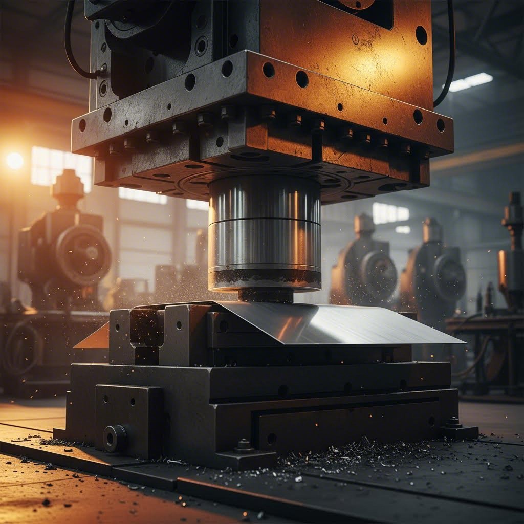
Perimmiltään levyteräksen puristusmuotti on erikoistunut työkalu, joka on suunniteltu leikkaamaan, taivuttamaan tai muovaamaan tasaisia metallilevyjä kolmiulotteisiksi muodoiksi ohjatun voiman avulla. Ajattele sitä älykkäänä keksileivontakoneena – mutta sen sijaan, että se muovaa taikinaa, se toimii vahvan metallin kanssa valtavan paineen alaisena. Muottisarja koostuu yleensä kahdesta pääkomponentista: yläosasta, jota kutsutaan nimellä työntöpää, ja alaosasta, jota kutsutaan nimellä muotti. Kun nämä komponentit asetetaan metallipuristimeen, ne toimivat yhdessä tuodakseen tuhansia tonneja tarkasti ohjattua voimaa.
Metallin muuntamisen tekniikka
Pressimuottien toiminnan ymmärtäminen edellyttää niiden keskeisten komponenttien välisten suhteiden tarkastelua. Kun metallia puristetaan, ylätyöntöpää laskeutuu alapuolella olevan muotin suuntaan, ja metallilevy on sijoitettu näiden kahden komponentin väliin. Tämä vuorovaikutus mahdollistaa metallin muuntamisen neljän olennaisen toiminnon kautta:
- Sijainti: Metallilevyn tarkka sijoittaminen juuri siihen paikkaan, jonne se kuuluu
- Kiinnitys: Materiaalin kiinnittäminen liikumisen estämiseksi muovauksen aikana
- Toiminta: Itse leikkaus-, taivutus- tai muovausoperaation suorittaminen
- Vapauttaminen: Valmiin komponentin irrottaminen työkaluista
Työtoiminto on se vaihe, jossa todellinen arvo syntyy. Tässä vaiheessa metallipainin suorittamat operaatiot kuten leikkaus, rei’itys, korostus, vetäminen ja kolikointi muuntavat raakamateriaalin toimiviksi muodoiksi.
Tämän tarkkuuden mahdollistavat useat kriittiset komponentit. Ylä- ja alapuolen muottikengät – jotka valmistetaan yleensä valuraudasta tai teräksestä – toimivat perustana, johon kaikki muut komponentit kiinnitetään. Näiden kengät täytyy kestää taipumista käytön aikana. Ohjauspinnit ja -putket pitävät muottipuolet kohdallaan; pinnit, jotka on valmistettu kovennetusta teräksestä, menevät pehmeämpien pronssiputkien läpi varmistaakseen tarkan sijoittelun miljoonien käyttökertojen ajan.
Litteästä lähtöaineesta valmiiksi osiksi
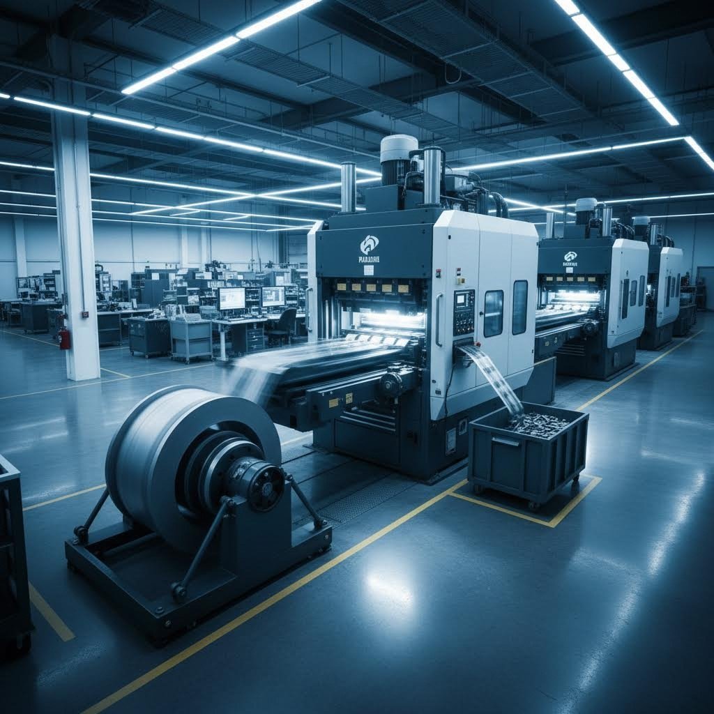
Kuvittele litteän alumiinilevyn liu'uttamista työkalupressin työntäjän ja kiskon väliin. Kun pressi toimii syklin mukaisesti, työntäjän kärki työntää metallia kiskon aukeamaan ja liu'uttaa sitä kiskon olkapään säteiden yli. Seuraava vaihe riippuu siitä, mikä tietty operaatio suoritetaan – esimerkiksi koko muodon leikkaaminen, reikien tekeminen tai monimutkaisten taivutusten muodostaminen.
Nykyaikaisten pressikiskojen tarkkuus mahdollistaa erinomaisen asian: kyvyn tuottaa miljoonia identtisiä osia johdonmukaisella laadulla. Tämä toistettavuus johtuu seuraavista tekijöistä:
- Tiukat valmistustoleranssit kaikissa kiskokomponenteissa
- Kovennetut työkaluteräkset, jotka kestävät kulumista pitkien tuotantosarjojen aikana
- Tarkat sijoitusjärjestelmät, jotka varmistavat sijoituksen tarkkuuden
- Laskennallisesti määritellyt välykset työntäjän ja kiskon pintojen välillä
Miksi tämä on tärkeää nykyaikaiselle valmistukselle? Harkitse ensin tehokkuutta. Hyvin suunniteltu muotti voi tuottaa valmiita osia nopeuksilla, joita manuaaliset valmistusmenetelmät eivät voi saavuttaa. Laadun yhdenmukaisuus seuraa – jokainen komponentti syntyy samanmittaisena ja samankaltaisina ominaisuuksiltaan. Lopuksi kustannustehokkuus paranee merkittävästi, kun tuotantomäärät kasvavat, sillä alussa tehtävä työkalutuotantoinvestointi jakautuu miljoonille osille.
Olet sitten insinööri, joka määrittelee työkaluja uuteen projektiin, tai valmistusalan ammattilainen, joka haluaa ymmärtää puristimien ja muottien perusteet – näiden perusteiden hallinta muodostaa pohjan informoitujen päätösten tekemiselle muottien valinnassa, suunnittelussa ja hankinnassa. Seuraavat luvut rakentuvat tähän tietoon, ohjaamalla sinut muottityyppien luokittelun, teknisten eritelmien ja oikean kumppanin valinnan salaisuuksien läpi työkalutarpeitasi varten.
Täydellinen muottityyppien luokittelu ja niiden sovellukset
Nyt kun olet ymmärtänyt, miten levyteräksen puristinmuotteja käytetään muuntaa tasainen lähtöaine valmiiksi komponenteiksi , seuraava kysymys on: mitä tyypin muottia sinun pitäisi käyttää? Tämä päätös vaikuttaa kaikkeen: tuotantokustannuksiin, osien laatuun – ja väärä valinta voi tarkoittaa tuhansia dollareita hukattuja työkalukustannuksia tai menetettyjä tehostamismahdollisuuksia.
Muottisarjat jaetaan viiteen pääluokkaan, joista jokainen on suunniteltu ratkaisemaan tiettyjä valmistusongelmia. Jokaisen suunnittelun taustalla olevan logiikan ymmärtäminen auttaa sinua valitsemaan tuotantovaatimuksiesi mukaisen työkalujärjestelmän. Käydään läpi kunkin tyypin ominaisuudet ja tutkitaan, milloin yhtä tyypistä kannattaa käyttää toisen sijaan.
Edistyneet muotit suurten sarjojen tehokkuuteen
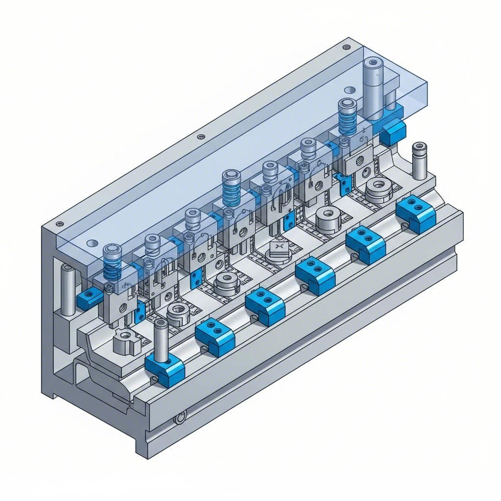
Kuvittele muottipressi, joka suorittaa reiäntyönnön, taivutuksen ja leikkaamisen – kaikki yhdessä konekierron aikana. Juuri tämän mahdollistavat edistävät muotit. Nämä monitasoiset työkalumuotit koostuvat useista peräkkäisistä työasemista, jotka on järjestetty sarjaksi yhteen muottisarjaan, ja jokainen työasema suorittaa eri operaation metallinauhan edetessä työkalun läpi.
Tässä on kuinka se toimii: levykierre syötetään ensimmäiseen asemaan, jossa suoritetaan alustava toimenpide – esimerkiksi ohjausreikien poraus. Jokaista puristuspientä kohti materiaali etenee kiinteän matkan seuraavaan asemaan. Kun nauha saavuttaa viimeisen aseman, valmis osa irtoaa kokonaan muodostuneena. Samalla seuraava osa on jo edennyt useita toimenpiteitä taaksepäin.
Tämän suunnittelun insinöörillinen nerokkuus piilee sen kyvyssä saavuttaa iskutaajuudet 30–60+ iskua minuutissa. Lähteessä HE-Machine:n tuotantolinjan analyysi edistävät muottia käytetään erityisesti pieniin rakenteellisiin osiin, joita tarvitaan paljon, ja joissa tehokkuus ja tuotantomäärä ovat tärkeimmät tekijät.
Edistävien muottien keskeiset edut ovat:
- Erittäin korkeat tuotantonopeudet vähällä työvoimavalvonnalla
- Tiukka sijoittelupaikka, koska yksi muotti puristimeen hoitaa kaikki toimenpiteet
- Yhtenäinen osalaatu automatisoidun materiaalin käsittelyn ansiosta
- Alhaisemmat kustannukset osaa kohden suurilla tuotantomäärillä
Kompromissi? Materiaalin hyötyosuus on yleensä alhaisempi, koska nauhan on säilytettävä vakaa etäisyys välillä eri työvaiheiden välillä. Edistävät muotit vaativat myös merkittävän alkuperäisen investoinnin ja niiden virheenkorjaus asennuksen aikana voi olla haastavaa.
Siirtomuotit: joustavuus kohtaa automaation
Mitä tehdään, jos osasi ovat liian suuria jatkuvaa nauhaa varten tai muotoilutyövaiheet edellyttävät työkappaleen liikkumista useaan eri suuntaan? Siirtomuotit ratkaisevat tämän haasteen sijoittamalla useita riippumattomia muotteja yhteen suuritehoiseen muotoilupuristimeen, jolloin mekaaniset kädet siirtävät osia asemalta toiselle.
Toisin kuin edistävissä muoteissa, joissa materiaali pysyy yhtenäisenä, siirtopursotuksessa käytetään joko valmiiksi leikattuja levyjä tai keloista leikattua materiaalia ensimmäisessä asemassa. Automaattiset sormet tai tarttumalaitteet kuljettavat sitten jokaisen osan seuraaviin työvaiheisiin. Tämä menetelmä toimii erinomaisesti palkkimaisille komponenteille, vahvistuosille ja monimutkaisten geometristen muotojen omaaville symmetrisille osille.
Muokkauspuristin, joka käyttää siirtodie-työkaluja, saavuttaa tyypillisesti 20–30 iskua minuutissa – hitaammin kuin edistävä leikkaus, mutta huomattavasti nopeammin kuin manuaalinen käsittely erillisissä puristimissa. Todellinen etu tulee esille osissa, jotka olisivat epäkäytännöllisiä valmistaa nauhalla: suuremmat komponentit, monisuuntaiseen muovaukseen vaativat osat sekä suunnittelut, joiden ominaisuuksia voidaan tarttua automatisoituja siirtomekanismeja käyttäen.
Kun yhdistelmädie-työkalut ylittävät yksinkertaisen työkalujärjestelmän suorituskyvyn
Joskus useita leikkaustoimintoja on suoritettava samanaikaisesti täsmälleen samassa paikassa. Yhdistelmädie-työkalut tarjoavat tämän mahdollisuuden suorittamalla kaksi tai useampia leikkaustoimintoja – kuten tyhjäleikkausta ja rei’itystä – yhdellä puristusiskulla yhdessä työasemassa.
Kuvitellaan pesurielinten valmistusta: sinun täytyy leikata ulkohalkaisija ja porata keskusreikä. Yhdistetty muottityökalu suorittaa molemmat toimenpiteet samanaikaisesti, mikä takaa täydellisen keskikohdallisuuuden ulkoisen reunan ja sisäisen reiän välillä. Tätä tarkkuutta olisi vaikea saavuttaa erillisillä toimenpiteillä, koska jokainen käsittelyvaihe tuo mukanaan mahdollisia sijoitusvirheitä.
Yhdistetyt muottityökalut ovat erinomaisia, kun:
- Osaan liittyvät piirteet vaativat tarkkaa sijoittelua suhteessa toisiinsa
- Tuotantomäärät oikeuttavat monimutkaisemman muottityökalun suunnittelun
- Tasaisuus ja mitallinen tarkkuus ovat kriittisiä vaatimuksia
Yhdistetyt ja yksinkertaiset muottityökalut: oikean kokoinen investointi
Yhdistetyt muottityökalut yhdistävät leikkaus- ja muotoilutoimenpiteet yhdessä iskussa – esimerkiksi tyhjäleikkaus muodostetaan samanaikaisesti taivutuksen tai vetämispiirteen luomisen kanssa. Tämä menetelmä vähentää käsittelyä ja parantaa osan tarkkuutta silloin, kun leikattujen reunojen ja muotoiltujen piirteiden väliset geometriset suhteet ovat merkityksellisiä.
Toisella ääripäässä monimutkaisuusasteikkoa yksinkertaiset muotit suorittavat ainoastaan yhden toiminnon iskua kohden. Tarvitsetko reiän poraamista? Levyreunan taivuttamista? Reunan leikkaamista? Yksinkertainen muotti hoitaa jokaisen tehtävän erikseen. Vaikka tämä vaatii osien siirtämistä eri toimintojen välillä, työkalujen kustannukset ovat vähäiset ja asennus on suoraviivainen.
Prototyypitykseen, pieniin tuotantomääriin tai vain yhden muovauksen vaiheen vaativiin osiin yksinkertaiset muotit ovat usein taloudellisesti kannattavin vaihtoehto. Hydrauli-pressin muottisijoituksen kustannukset pysyvät alhaisina, ja säilytät joustavuuden muokata prosessia ilman kalliiden työkalujen hylkäämistä.
Muottityyppien vertailu: Valintasi opas
Näiden lähestymistapojen valinta edellyttää tasapainottelua tuotantomäärän, osan monimutkaisuuden, budjettirajoitusten ja laatuvaatimusten välillä. Seuraava vertailu auttaa selkeyttämään, mikä muottityyppi sopii parhaiten tiettyyn valmistustilanteeseesi:
| Nelosuunnikksen tyyppi | Tuotannon määrä | Osaen kompleksisuus | Aikaa kokoonpanoon | Hintaväli | Tyypilliset sovellukset |
|---|---|---|---|---|---|
| Progressiivinen | Korkea (100 000+ osaa) | Matala – Keskitaso | Pitkä alustava, vähäinen kerralla | $$$-$$$$ | Sähkökontaktit, kiinnikkeet, pienet autoteollisuuden osat |
| Siirto | Keskitasoisesta korkeaan | Keskitasoisesta korkeaan | Kohtalainen | $$$$ | Rakenteelliset palkit, vahvistukset, symmetriset koteloit |
| Yhdiste | Keskitasoisesta korkeaan | Matala – Keskitaso | Kohtalainen | $$-$$$ | Pesurit, tarkkuuslevyt, osat, joissa vaaditaan keskikäyttöisyyttä |
| Yhdistelmä | Keskikoko | Keskikoko | Kohtalainen | $$-$$$ | Osat, jotka yhdistävät leikattuja reunoja muotoiltuihin ominaisuuksiin |
| Yksinkertainen | Matala – Keskitaso | Alhainen | Lyhyt | $-$$ | Prototyypit, yksitoimiset osat, pienemmän tuotantomäärän valmistus |
Huomaatko suhteen tilavuuden ja monimutkaisuuden välillä? Suurimittainen tuotanto oikeuttaa edistävän tai siirtotyökalujen sijoittamiseen, kun taas pienempi tuotantomäärä usein edistää yksinkertaisempia lähestymistapoja, joissa alustavat kustannukset ovat pienempiä. Sovelluksellesi optimaalinen ratkaisu riippuu tarkista tuotantovaatimuksistasi ja laatuvaatimuksistasi.
Kun tämä luokittelukehys on vakiintunut, olet valmis syventämään tuntemustasi teknisestä sanastosta, jota insinöörit ja työkalumiehet käyttävät näiden työkalujen ja niiden toimintojen kuvaamiseen.
Jokaisen insinöörin tulisi tuntea välttämättömät työkalusanat
Oletko koskaan yrittänyt keskustella työkalujen vaatimuksista muottitekijän kanssa ja tuntenut itsesi eksyneeksi merellä tuttomia termejä? Et ole yksin. Levyteräsmuottien sanaston hallinta muuttaa sekavat keskustelut tuottaviksi yhteistyöksi — ja auttaa sinua lukemaan teknistä dokumentaatiota luottavaisesti.
Tarkastellessasi tarjousta muottityökalutoimittajalta tai korjatessasi tuotantoon liittyviä ongelmia näiden perustermien ymmärtäminen antaa sinulle hallinnan. Rakennetaan sanastoa systemaattisesti: aloitamme leikkaustoiminnoilla, joilla poistetaan materiaalia, ja siirrymme sitten muovausoperaatioihin.
Leikkaustoiminnot selitetty
Leikkaustoiminnot poistavat materiaalia työkappaleesta, luoden muotoja, reikiä tai erottamalla valmiit osat raakamateriaalista. Jokainen leikkaustermi kuvaa tiettyä toimintaa, jolla on omat erityispiirteensä:
- Leikkaus: Koko muodon leikkaaminen levyteräksestä jossa poistettu osa muodostaa valmiin osan. Ajattele esimerkiksi metallilevystä leikattavaa kiekkoa, joka tulee olemaan hammaspyörä – kiekko on sinun "raakapalas". Manor Toolin sanastomääritelmän mukaan raakapala on sekä tuotteen valmistukseen käytetty levytä, että blankausprosessin tuloksena saatu osa.
- Poraus: Reikien tai loven leikkaaminen materiaaliin iskemällä läpi sen. Toisin kuin blankauksessa, poistettu materiaali (jota kutsutaan pohjalevyksi) on jätteeksi, kun taas reiällä varustettu jäljelle jäänyt levy muodostaa valmiin osan. Porausleikkureita varten suunnitellut puristinleikkurit täytyy kyetä poistamaan pohjalevy selkeästi estääkseen lukkiutumisen.
- Notkinta: Metallijätteen leikkaaminen työkappaleen ulkoisilta reunoilta – toisin sanoen poraus tapahtuu osan kehän pitkin eikä sisäosien läpi.
- Leikkaus: Suoraviivaisten leikkausten tekeminen, kun levy kulkee ylä- ja alapuolisten terien välissä. Tämä toiminto toimii kuin teollisuusleikkurit, jotka leikkaavat materiaalin määritellyn polun pitkin.
Kun leikkaustoimenpiteitä suoritetaan, kaksi sivutuotetta vaativat huomiota. pommi on jäännösjäte pistossa—ne pienet metallikiekot, jotka putoavat työkalun läpi. jätesiirtymämerkki syntyy, kun jätemateriaali puristuu työkappaleen pintaan, mikä aiheuttaa virheen. Jäteosien asianmukainen käsittely estää kalliita laatuongelmia.
Muovaus vastaan vetäminen
Tässä vaiheessa nimitykset usein sekoittuvat: sekä muovaus että vetäminen muokkaavat metallia, mutta ne tekevät sen perustavanlaatuisesti eri mekanismein. Erotteen ymmärtäminen auttaa sinua valitsemaan oikeat työkalut sovellukseesi.
Muovausoperaatiot taivuttaa tai muotoilla materiaalia merkittävän materiaalin virtauksen ilman. Metallin paksuus pysyy käytännössä vakiona, koska muutat ainoastaan kulmaa tai kaarevuutta. Muovaustyökalulla voidaan esimerkiksi luoda 90 asteen reunus kiinnityslevyyn—metalli taipuu, mutta sitä ei venytetä tai ohenneta huomattavasti.
- Taivutus: Metallilangan kulmamuutos työkalun avulla määriteltyjen kulmien luomiseksi
- Laitanmuotoilu: Vahvistetun reunan luominen, usein helpottamaan kokoonpanoa tai lisäämään jäykkyyttä
- Reunauksenteko (hollanninkainen taivutus): Materiaalin reunan kaksinkertainen taittaminen itsensä yli reunojen jäykentämiseksi tai terävyyden vähentämiseksi
Muovausoperaatiot syvyys luodaan pakottamalla materiaali virtaamaan muottikammioon. Tässä muottimuovauksessa metallia todellisuudessa venytetään, mikä aiheuttaa sen ohentumisen muotoutumisen aikana. Syvävetomuovaus tuottaa onttoja komponentteja – esimerkiksi juomakannut tai auton moottoriöljypannut – joissa tasainen lähtöaine muuttuu kupinmuotoisiksi osiksi.
Tärkein tunnusmerkki? Jos osan syvyys on merkittävä suhteessa sen halkaisijaan ja seinämän paksuus on ohuempi kuin alkuperäinen levy, muovaus on ollut mukana. Osat, joiden paksuus säilyy alkuperäisenä, ovat yleensä peräisin muovausmuoteista.
Tarkkuusmuovausoperaatiot
Jotkin operaatiot vaativat erinomaista tarkkuutta tai luovat koristeellisia piirteitä. Nämä erikoistuneet menetelmät saattavat usein valmiiksi muottimuovatun osan:
- Kolmintekniikka: Tarkka puristusprosessi, jossa työkappale läpäisee neutraalitason korkean paineen vaikutuksesta sekä työntöpään että muottia samanaikaisesti. Tämä mahdollistaa erinomaiset tarkkuustoleranssit ja sileät pinnat – mikä on välttämätöntä osille, joille vaaditaan täsmällisiä mittoja.
- Painatus: Korostettujen tai syvätyttyjen kuvioiden muodostaminen levymetallille ilman leikkaamista läpi. Logot, tekstuurit ja toiminnallisesti tärkeät piirteet, kuten jäykistysripat, syntyvät usein korostusleikkauksessa.
- Puolileikkaus: Levymetallin osittainen läpäiseminen luodakseen ulokeen, jonka korkeus on noin puolet materiaalin paksuudesta. Nämä korostetut piirteet toimivat sijoitusapuna hitsausta tai kokoonpanoa varten.
Tärkeät tukitermit
Toimintojen lisäksi useat termit kuvaavat olosuhteita, virheitä tai muottien ominaisuuksia, joita kohtaat säännöllisesti:
- Muovin välys: Työntöpään ja muottiaukon välinen välys. Oikea välys vaikuttaa leikkausreunan laatuun, työkalun kestoon ja irrotusvoimaan. Liian pieni välys aiheuttaa liiallista kulumista; liian suuri välys taas synnyttää teräkset ja mittasuhteita heikentäviä ongelmia.
- Poisto: Työkappaleen tai romun poistaminen työkalusta (pistäimestä) toimenpiteen jälkeen. Poistimet kohdistavat voiman materiaalin irrottamiseksi työkalusta sen vetäytyessä.
- Reunakärki: Leikkaustoimenpiteiden jäljelle jäävät kohoavat reunat tai terävät ulokkeet. Karvat muodostuvat enemmän, kun leikkurin välys on virheellinen tai työkalut tulevat tumpeloinen.
- Kimmoisuus: Kun kimmoisa materiaali osittain palautuu muotoaan muovauksen jälkeen. Springback-vaikutuksen huomioiminen muottisuunnittelussa varmistaa, että osat täyttävät lopulliset mitalliset vaatimukset.
- Rikkoutuminen: Materiaalin osa, joka murtuu leikkauksen aikana – näkyy leikattujen reunojen karkeana alueena verrattuna leikattuun pintaan.
Tämän sanastoperustan avulla olet valmis viestimään tarkasti muottienvalmistajien kanssa, tulkkaamaan teknisiä piirroksia ja ratkaisemaan tuotantoon liittyviä ongelmia. Seuraavaksi tutustumme niin sanottuihin teknisiin eritelmään, jotka määrittelevät, miten nämä toimenpiteet suoritetaan – aloittaen tonniajan laskennasta, joka määrittää, pystyykö puristimesi suorittamaan tehtävän.
Muottisuorituskykyä ohjaavat tekniset eritelmät
Olet hallinnut terminologian. Ymmärrät työkalutyypit. Mutta tässä on kysymys käytännön toteuttamisesta: tekniset tiedot määrittävät, tuottaaako työkalusi laadukkaita osia vai kalliita romuja. Näiden lukujen väärä määrittäminen johtaa liian pieniin puristimiin, jotka taipuvat kuormasta, työkalujen ennenaikaiseen vikaantumiseen tai osiin, jotka eivät täytä mittoja koskevia vaatimuksia.
Käydään läpi kriittisiä laskutoimituksia ja teknisiä tietoja, jotka erottavat onnistuneet työkalukäytöt kalliista virheistä. Riippumatta siitä, määritteletkö uutta metallipainokonetta vai arvioitko olemassa olevaa työkalua, nämä perusteet ovat yleispäteviä.
Painokoneen tonniajan laskeminen
Oletko koskaan miettinyt, miksi jotkin työkalut toimivat moitteettomasti yhdessä painokoneessa, mutta epäonnistuvat toisessa? Vastaus liittyy usein tonniajaan – voimaan, jonka painokoneen on tuotettava operaation suorittamiseksi. Aliarvioitua tonniajaa käyttäessä painokoneesi työstötoiminto pysähtyy iskun keskellä. Yliarvioitu tonniaja taas tarkoittaa, että maksat kapasiteetista, jota et koskaan käytä.
Leikkaustoimintojen peruskaava on suoraviivainen:
Tonniajako = (Leikkauspiiri × materiaalin paksuus × materiaalin leikkauslujuus) ÷ 2000
Näyttää yksinkertaiselta? Tarkastellaan tarkemmin, mitä kukin tekijä tarkoittaa:
- Leikkauspiiri: Kaikkien samanaikaisesti tehtävien leikkausten kokonaispituus tuumina. Esimerkiksi 3 tuuman halkaisijaltaan olevan ympyrän ja neljän 0,25 tuuman reiän tapauksessa lasketaan: (π × 3) + (4 × π × 0,25) ≈ 12,57 tuumaa.
- Materiaalin paksuus: Materiaalin paksuus tuumina. 0,060 tuuman teräslevy käyttäytyy eri tavoin kuin 0,250 tuuman levy.
- Leikkauslujuus: Materiaalin kestävyys ennen murtumista, mitattuna naulaa neliötuumaa kohti (PSI). Pehmeän teräksen leikkauslujuus on noin 50 000 PSI, kun taas ruostumatonta terästä on 75 000–90 000 PSI.
Käytännön esimerkki: 4 tuuman neliön muotoisen levyn leikkaaminen 0,125 tuuman pehmeästä teräksestä. Piiri on 16 tuumaa. Sijoitetaan arvot kaavaan: (16 × 0,125 × 50 000) ÷ 2000 = vaaditaan 50 tonnia.
Mutta hetkinen—tätä peruslaskelmaa on säädettävä. Tekijät, jotka kasvattavat todellisia tonnia vaativia vaatimuksiasi, ovat muun muassa:
- Tylsät leikkuuterät (lisää 10–30 % lisävoimaa)
- Epäsopiva työkalun välys (vaadittava tonnimäärä voi kaksinkertaistua)
- Useita samanaikaisia toimintoja
- Materiaali, joka on kovempaa kuin nimellisvaatimukset
- Edellisen muovauksen aiheuttamat kylmämuovaukseen liittyvät vaikutukset
Useimmat insinöörit käyttävät lasketuista vaatimuksista 20–30 %:n turvatekijää. 100 tonnin kapasiteetilla varustettua konepistotyökalua ei tulisi säännöllisesti käyttää yli 70–80 tonnin kuormituksella, jotta koneen kestoikä ja suorituskyky pysyvät tasaisina.
Materiaalin paksuusalueet ja työkalun suunnittelun vaikutus
Materiaalin paksuus vaikuttaa ei ainoastaan vaadittavaan tonnimäärään, vaan se muuttaa perusteellisesti myös sitä, miten työkalukomponenttejasi on suunniteltava. Ohuemmat materiaalit vaativat tiukempia välyksiä ja tarkempaa keskitystä, kun taas paksumpi materiaali edellyttää vankempaa rakennetta ja suurempia muovausradiuksia.
Ota huomioon seuraavat paksuuteen liittyvät suunnittelutekijät:
- Ohut levy (alle 0,030 tuumaa): Edellyttää tarkkuusleikkauslevyjä, joissa on mahdollisimman vähän taipumaa, tiukempia välejä (yleensä 3–5 % paksuudesta kummallakin puolella) ja huolellisesti suunniteltua irrotusmekanismia vääntymisen estämiseksi.
- Keskiverto levy (0,030–0,125 tuumaa): Tämä on useimpien leikkausoperaatioiden optimaalinen alue. Standardivälit 5–8 % paksuudesta kummallakin puolella toimivat hyvin, ja perinteinen työkalurakennus kestää kuormat.
- Paksu levy (0,125–0,250 tuumaa): Edellyttää raskaampia työkalupohjia, suurempia työntäjän ja leikkauslevyn välejä (8–12 % paksuudesta kummallakin puolella) sekä suurempia muotoilusäteitä halkeamien estämiseksi.
- Levy (yli 0,250 tuumaa): Vaatii usein hydraulisen puristimen työkalut riittävän voiman saavuttamiseksi, erikoisteräksiä ja teknistä analyysiä työkalukomponenttien lujuuden varmistamiseksi.
Työkalulevyn paksuuden on itseään skaalaututtava työstettävän materiaalin mukaan. Yleinen suuntaviiva: työkalulevyjen tulisi olla vähintään 1,5-kertaiset työstettävän materiaalin paksuisia, ja lisämassaa on lisättävä korkeatonnisten operaatioiden tai kovennettujen materiaalien käsittelyyn.
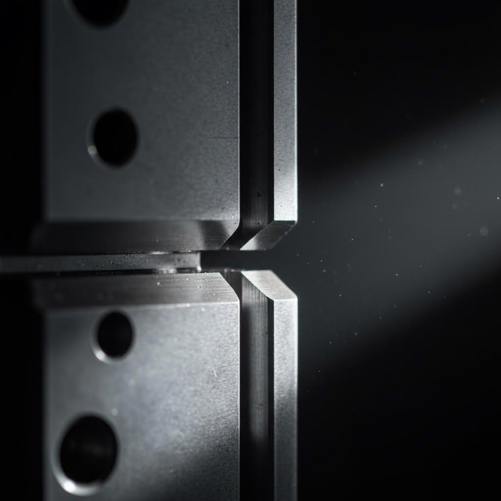
Työkaluvälin ymmärtäminen ja sen vaikutukset
Työkalun ja kuulakkeen välinen välys—eli työkalun ja kuulakkeen aukon välinen väli—saattaa vaikuttaa pieneltä yksityiskohdalta. Todellisuudessa se on yksi tärkeimmistä määristä, jotka vaikuttavat leikkausreunan laatuun, työkalun kestoon ja mittojen tarkkuuteen.
Oikea välys tuottaa siistin murtumakuvion leikkauksen aikana. Liian pieni välys aiheuttaa liiallista kulumista leikkausreunoille, lisää tarvittavaa leikkauspainoa ja mahdollisesti jyrsimen murtumisen. Liian suuri välys puolestaan aiheuttaa teräspätkiä, pyörähtelyä ja epätasaisia mittoja.
Optimaalinen välys riippuu pääasiassa materiaalin tyypistä ja paksuudesta:
| Materiaalilaji | Suositeltu pelte (% paksuudesta kummallakin puolella) | Liian pienen välyksen vaikutus | Liian suuren välyksen vaikutus |
|---|---|---|---|
| Mieto teräs | 5-8% | Toissijainen leikkaus, työkalun kuluminen | Paksut teräspätkät, pyörähtely |
| Ruostumaton teräs | 6-10% | Kulumisilmiö (galling), jyrsimen tarttuminen | Liialliset teräspätkät |
| Alumiini | 4-6% | Reunan repäisy, kertymä | Karkeat reunat, mittojen poikkeamat |
| Kupari/Messinki | 3-5% | Materiaalin tarttuvuus | Muodonmuutokset, terävät reunat |
| Korkean vahvuuden teräs | 8-12% | Pistotyökalun murtuminen, sirontaminen | Heikko reunalaatu |
Muuromuottien ja raskaiden muovausoperaatioiden tapauksessa välysten laskeminen muuttuu monimutkaisemmaksi. Vetämis- ja taivutusoperaatiot vaativat välyksiä, jotka ottavat huomioon materiaalin virtaamisen eivätkä perustu pelkästään leikkausmekaniikkaan.
Toleranssimahdollisuudet ja mitallinen tarkkuus
Mitkä toleranssit voit todellisuudessa saavuttaa? Vastaus riippuu muottisi tarkkuudesta, puristimen kunnosta ja materiaalin yhdenmukaisuudesta. Tässä on odotettavissa olevaa:
- Standardilevytys: ±0,005"–±0,010" leikattujen mittojen osalta
- Täsmällinen leimaus: ±0,001"–±0,003" maatunutta työkalua ja tiukkoja puristinpalkkeja käytettäessä
- Muovatut mitat: Yleensä ±0,010"–±0,015" jousipalautuman vaihtelun vuoksi
- Reiän ja reiän väli: Usein saavutettavissa ±0,002":n tarkkuudella tarkkuusmuottikomponentteja käyttäen
Muista: osiesi tarkkuus ei voi olla parempi kuin heikoimman lenkin tarkkuus. Tarkkuusmuotti, joka toimii kuluneessa puristimessa löysillä puristinpalkkeilla, ei tuota tiukkoja toleransseja. Samoin epätasainen materiaalin paksuus aiheuttaa mitallista vaihtelua riippumatta työkalujen laadusta.
Kun nämä tekniset tiedot ovat selviä, olet valmis tutkimaan, miten eri materiaalit käyttäytyvät muovauksessa – sekä mitkä muottisuunnittelut soveltuvat parhaiten kuhunkin materiaaliin. Materiaaliyhteensopivuus määrittää usein sen, toteutuuko lasketut tekniset vaatimukset tuotannossa onnistuneesti.
Materiaaliyhteensopivuus ja muottivalintasuositukset
Olet laskenut tonniamäärävaatimuksesi ja määrittänyt tarkasti välistövaatimukset. Mutta tässä on kysymys, joka aiheuttaa vaikeuksia jopa kokemuksellisille insinööreille: vastaako levyteräsmuottisuunnitteluasi todella muovattavaa materiaalia? Eri metallit käyttäytyvät eri tavoin paineen alaisena – ja näiden erojen sivuuttaminen johtaa kuluneisiin muottiosiin, halkeamiin osissa ja tuotantohankaluuksiin.
Ajattele asiaa näin: pehmeä teräs antaa anteeksi huolimatonta työtapaa. Alumiini rankaisee sitä. Korkealujuusteräs vaatii kunnioitusta. Ymmärtäminen siitä, kuinka kukin materiaali reagoi muovauksen aikana, auttaa sinua valitsemaan oikean teräsmuotin, valitsemaan sopivat voiteluaineet ja välttämään kalliita yllätyksiä tuotantolinjalla.
Muottisuunnittelun sovittaminen materiaalin ominaisuuksiin
Jokaisella levymetallilla on oma persoonallisuutensa. Jotkut venyvät hal willingly; toiset taistelevat takaisin jousipalautuksella. Jotkut liukuvat sujuvasti työkalupintojen yli; toiset tarttuvat kiinni ja repivät. Tässä on tietoa jokaisesta tärkeästä materiaaliryhmästä:
Harkkuteräs (hiiliteräs): Levein materiaali levytelineiden valmistukseen. Se muotoutuu ennustettavasti, hyväksyy laajan välysten alueen ja ei vaadi erikoislisäaineita voiteluun. Standardit työteräkset, kuten D2 tai A2, käsittelevät pehmeää terästä erinomaisesti. Jos olet uusi telineiden suunnittelussa tai prototyypitset prosessia, pehmeä teräs on erinomainen lähtökohta.
Muut, joissa on vähintään 50 painoprosenttia: Tässä asioiden kiinnostavuus kasvaa. Ruostumaton teräs kovettuu nopeasti muotoutumisen aikana, mikä tarkoittaa, että se kovettuu ja vahvistuu sitä mukaa kuin sitä muovataan. Tämä aiheuttaa kaksi haastetta: lisääntynyt jousitus (osat eivät säilytä muotoutunutta muotoaan) ja korkeammat tonnivaatimukset, kun toimenpiteet edistyvät. Levytelineet ruostumattomalle teräkselle vaativat usein ylikiertymistä 2–4 astetta, jotta voidaan kompensoida kimmoista palautumista.
Korkean lujuuden teräs: Autoalan sovelluksissa käytetyt edistyneet korkealujuus teräkset (AHSS) voivat vaatia 50–100 % enemmän puristusvoimaa kuin saman paksuiset pehmeät teräkset. Nämä materiaalit aiheuttavat myös nopeutettua työkalumuottien kulumista, mikä edellyttää korkealaatuisia työkaluteräksiä, kuten karbidia tai jauhemetallurgisia laadukkaita, jotta työkaluilla olisi kohtalaisen pitkä käyttöikä.
Kupari ja messingi: Pehmeät metallit aiheuttavat omia haasteitaan. Ne ovat alttiita adheesiolle—ne tarttuvat työkalun pisteen pinnalle—ja voivat muovautua puristuspaineen vaikutuksesta. Kiillotettu työkalu ja sopivat välykset estävät näiden esteettisesti herkkien materiaalien naarmuuntumisen.
Erityishuomioita ruostumattomasta teräksestä ja alumiinista
Alumiini vaatii erityistä huomiota, koska se on yhtä aikaa suosittu ja ongelmallinen. Keveä ja korroosioresistentti alumiini esiintyy kaikenlaisissa tuotteissa, sähkölaitteiden koteloista autojen paneelien kautta. Mutta alumiini muodostaa galleja—se hitsautuu itsestään terästyökaluihin paineen ja kitkan vaikutuksesta.
Alumiinin gallien ehkäisemiseen vaaditaan monitasoinen lähestymistapa:
- Käytä kiillotettuja muottipintoja (mieluiten peilikirjaimisia)
- Käytä kestäviä voiteluaineita tai erityisiä alumiinimuokkausaineita
- Harkitse pinnoitettuja työkaluja (TiN-, TiCN- tai DLC-pinnoitteet vähentävät kitkaa)
- Pidä tiukemmat välykset (4–6 % kummaltakin puolelta) materiaalin virran minimointia varten nuppipintojen vastaisesti
Kun painettavaa levyterästä vaaditaan ruostumattomaksi, muistettakoon, että austeniittiset laadut (304, 316) käyttäytyvät eri tavoin kuin ferriittiset tai martensiittiset laadut. Austeniittinen ruostumaton teräs kovettuu työstön aikana voimakkaimmin, mikä edellyttää vaiheittaista muokkausasteikon lieventämistä useiden muottiasemien yli. Ruostumattomalle teräkselle suunnitellut metallilevytysmuottisarjat sisältävät usein välilämmitysasemia työstökovettumisen poistamiseksi raskaiden vetotyövaiheiden välillä.
Materiaalivalinnan nopea viite
Seuraava taulukko tiivistää tärkeimmät ominaisuudet ja haasteet yleisimmille levymetalleille. Käytä tätä lähtökohtana, kun määrittelet metallimuottisi vaatimukset:
| Materiaali | Muottivälys (% kummaltakin puolelta) | Tonnituskerroin | Yleiset haasteet | Suositeltava työkaluteräs |
|---|---|---|---|---|
| Mieto teräs | 5-8% | 1.0× (perustaso) | Vähäinen; suvaitseva materiaali | D2, A2, O1 |
| Ruostumaton teräs | 6-10% | 1.5-1.8× | Kimmoilu, työkovettuminen, kulumisliimaantuminen | D2 (kovennettu), M2, karbidipäät |
| Alumiini | 4-6% | 0.5-0.7× | Kulumisliimaantuminen, pinnan naarmuuntuminen, kerääntyminen | Hiottu D2, pinnoitettu karbidi |
| Kupari/Messinki | 3-5% | 0.4-0.6× | Adheesio, pehmeän pinnan merkitseminen | Hiottu A2, pronssilaakeroidut teräkset |
| Korkean vahvuuden teräs | 8-12% | 1.5-2.0× | Erinomainen työkalukuluminen, työntöpään murtuminen | Karbidi, PM-työkaluteräkset, pinnoitetut |
Huomaatko, kuinka voitelun vaatimukset kasvavat materiaalin käsittelyn vaikeuden mukana? Pehmeä teräs voidaan usein käsitellä perusleikkausöljyillä. Alumiini ja ruostumaton teräs vaativat erikoisyhdisteitä – joskus niitä sovelletaan sekä nauhalle että suoraan työkalupintojen pinnalle. Levymetallityökalusi kestävät huomattavasti pidempään, kun voitelu vastaa materiaalin käyttäytymistä.
Materiaaliyhteensopivuus vaikuttaa suoraan kokonaishankintakustannuksiisi. Väärän työkaluteräksen valinta korkean lujuuden sovelluksiin johtaa usein terävöitymiseen tai vaihtoon. Alumiinin tarttumisilmiön sivuuttaminen tuhoaa kalliit työkalupinnat. Kun materiaalin käyttäytymistä ymmärretään, olet valmis arvioimaan eri muottiratkaisujen taloudellisuutta ja määrittämään, milloin kalliimman työkalun sijoittaminen todella kannattaa.
Kustannusanalyysi älykkäiden muottisijoitusten päätösten tueksi
Tässä on kysymys, joka pitää valmistustekniikan insinöörejä hereillä yöllä: kannattaako sijoittaa 80 000 dollaria edistävään muottiin vai kuluttaa 8 000 dollaria yksinkertaiseen työkaluun? Vastaus ei ole yhtä suoraviivainen kuin hinnat vertaileminen. Kokonaishankintakustannukset riippuvat tuotantomäärästä, piilossa olevista toimintakustannuksista ja tekijöistä, jotka eivät koskaan näy alkuhinnassa.
Die-valinnan taloudellisen analyysin ymmärtäminen muuttaa arvaamista strategiseksi päätöksenteoksi. Olipa kyseessä uuden tuotteen markkinoille laskemiseen tarkoitetun puristusmuottisarjan arviointi tai olemassa olevien työkalujen käyttötapausten uudelleenarviointi, tämä kehys auttaa välttämään kaksi kalleinta virhettä: liiallista suunnittelua matalille tuotantomääriille ja riittämätöntä investointia korkeita tuotantomääriä varten.
Milloin etenevät muotit maksavat itsensä takaisin
Etenevät muotit ovat kalliita – monimutkaisten auto-osaisten osalta niiden hinta on usein 50 000–100 000 dollaria tai enemmän. Tämä alkuinvestointi pelottaa monet ostajat yksinkertaisempien vaihtoehtojen suuntaan. Mutta tässä on se, mitä hinnassa ei kerrota: korkeilla tuotantomääriillä etenevät työkalut tuottavat osakustannukseltaan selvästi alhaisimman kustannuksen kappaleelta.
Mukaan lukien Shaoyin autoalan puristusprosessin kustannusanalyysi , perusarviointikaava on:
Kokonaiskustannus = Kiinteät kustannukset (suunnittelu + työkalut + käyttöönotto) + (muuttuva kustannus/yksikkö × määrä)
Taikuus tapahtuu tuossa toisessa termissä. Edistävillä operaatioilla suunniteltu muottisarja voi saavuttaa iskunopeudet 30–60+ osaa minuutissa vähäisellä käyttäjän puuttumisella. Vertaa tätä yksinkertaisiin muotteihin, jotka vaativat manuaalista osien käsittelyä asemien välillä – äkkiä työvoimakustannukset hallitsevat taloudellista laskelmaasi.
Lasketaanpa luvut todellisesta skenaariosta. Kuvitellaan, että tarvitset 500 000 kiinnikettä viiden vuoden aikana:
- Edistävä muottimen lähestymistapa: 80 000 USD:n työkaluinvestointi ÷ 500 000 osaa = 0,16 USD osaa kohden työkalukustannuksissa. Lisää vähäinen työvoimakustannus korkean nopeuden tuotannossa, ja yksittäisen osan hinta pysyy alhaisena.
- Yksinkertainen muottimen lähestymistapa: 8 000 USD:n työkaluinvestointi ÷ 500 000 osaa = 0,016 USD osaa kohden työkalukustannuksissa. Kuulostaa paremmalta, eikö niin? Mutta otathan huomioon nyt manuaalisen käsittelyn kolmen erillisen operaation välillä, hitaammat sykliajat ja lisääntyneen laadunvalvonnan – työvoimakustannukset voivat lisätä yksittäisen osan hintaa 0,50 USD:lla tai enemmällä.
Kriittinen pistemäärä sijaitsee yleensä vuosittain 10 000–20 000 osassa, jolloin edistävän muottityypin tehokkuus kattaa sen korkeamman alustavan hinnan. Autoteollisuuden projekteissa, joiden tuotantomäärät ylittävät nämä kynnykset, monimutkaisten muottisarjojen sijoittaminen puristusoperaatioihin tuottaa alhaisimman kokonaishallintokustannuksen.
Kokonaishallintokustannukset muottihinnan yläpuolella
Muottitarjoukset kertovat vain osan tarinasta. Tuotantoprosessissasi piilevät piilotetut kustannukset ylittävät usein näkyvät kustannukset. Älykkäät muottisijoituspäätökset vaativat koko kuvan tarkastelua:
Asetus- ja vaihtoaikakustannukset
- Etenevät vahdit: Yksi asetus kaikille operaatioille. Kun käynnissä, vähän välihuoltoa vaaditaan.
- Useita yksinkertaisia muotteja: Jokainen operaatio vaatii erillisen asetuksen. Työvaihtoaikojen kertyminen työasemien välillä kasvaa moninkertaisesti.
- Siirtovalet: Kohtalainen asetuskompleksisuus, mutta automatisoitu käsittely vähentää työvoimakustannuksia kierrosta kohden.
Toissijaiset operaatiot ja käsittely
Joka kerta, kun osa siirtyy operaatiosta toiseen, kustannukset kertyvät. Hydrauliikkapuristimen muottisarja, joka suorittaa yksittäisiä operaatioita, tarkoittaa:
- Manuaalinen tai puoliautomaattinen osien siirto työasemien välillä
- Välivarastointi ja tuotantoprosessin keskivaikeat varastot
- Käsittelyn aiheuttaman vahingon riskin kasvu
- Lisäiset laatuinspektiopisteet
Edistävät muottit poistavat suurimman osan toissijaisesta käsittelystä. Osat kulkevat metallimuokkauspaineiden läpi jatkuvina nauhoina ja tulevat valmiiksi viimeisessä työasemassa.
Laatukontrollivaatimukset
Tässä on kustannusajuri, jota monet jättävät huomiotta: jokainen erillinen operaatio tuo mukanaan mittasuhteellisia vaihteluita. Kun metallimuokkausta tehdään useilla eri muoteilla, toleranssit kertyvät. Osaa, joka vaatii kolme operaatiota, saattaa olla tarkistettava jokaisen vaiheen jälkeen sekä lopullisen tarkistuksen yhteydessä. Edistävä työkaluvarustus säilyttää rekisteröinnin kaikkien operaatioiden ajan, mikä vähentää laatukontrollikuormaa ja hylkäysasteikkoa.
Huolto ja muottien käyttöikä
Teollisuuden tiedon mukaan miljoonaan iskukertaan taattujen korkealaatuisten muottien käyttö rajoittaa työkalujen kokonaishintaa tuotteen elinkaaren aikana tehokkaasti. Suurten sarjojen valmistuksessa tämä kustannusten jakaminen laskee osoitettuja työkalukustannuksia yksikköä kohden merkityksettömän pieneksi. Budjetoi työkalujen teroittamiseen ja komponenttien vaihtoon vuosittain noin 2–5 % työkalukustannuksista riippumatta muotin tyypistä.
Yleisesti esiintyvät väärinkäsitykset, jotka tuhoavat budjetit
Kaksi kalliita virhettä heikentää toistuvasti muottisijoituspäätöksiä:
Virhe #1: Liian suuri tekninen monimutkaisuus vähäisille tuotantomääriille. 60 000 dollarin edistävä muotti 5 000 kappaleen vuosittaiseen tuotantoon aiheuttaa pelkästään työkalukustannuksia 12 dollaria kappaleelta. Yksinkertaisemmin varustettu valmistuspaineen käyttö tuottaisi paremman taloudellisen tuloksen, vaikka työvoimakustannukset olisivatkin korkeammat. Sovita muotin monimutkaisuus todellisiin tuotantomääriin.
Virhe #2: Liian vähäinen sijoitus suurille tuotantomääriille. Yrittäminen säästää 50 000 dollaria työkaluinnosta, kun vuosittain valmistetaan 200 000 osaa, on valeekonomiaa. Tämän tuotantomäärän yhteydessä yksinkertaisten muottien aiheuttama työvoimatehottomuus ylittää helposti työkaluinnon säästöt jo ensimmäisenä vuonna. Laske kriittinen piste ennen sitoutumista.
Oikea lähestymistapa? Aloita ennustetusta tuotantomäärästä, laske kriittinen piste ja lisää sitten riittävä turvamarginaali tuotantomäärän epävarmuutta varten. Jos ennusteesi osoittaa 15 000 osaa vuodessa, mutta määrä voi vaihdella jopa 50 000 osaan, skaalautuvan edistävän muottityökalun sijoittaminen turvaa taloudellisen kannattavuutesi kummassakin tapauksessa.
Kun kustannusanalyysikehykset on asetettu paikoilleen, olet valmis tekemään taloudellisesti perusteltuja muottisijoituksia. Mutta vaikka parhaatkin työkalut vaativat asianmukaista huoltoa, jotta ne tuottaisivat odotetun arvon – mikä johtaa meidät huoltokäytäntöihin, jotka pidentävät muottien käyttöikää ja varmistavat osien laadun koko tuotantokauden ajan.
Muottien huolto ja vianetsintä – parhaat käytännöt
Olet sijoittanut tuhansia euroja tarkkuustyökaluihin. Painokonnesi tuottaa täydellisiä osia – toistaiseksi. Mutta tässä on epämukava totuus: ilman asianmukaista huoltoa tuo kallis konnesvaruste heikkenee jokaisella iskulla. Teräviä reunoja syntyy. Mittasuhteet poikkeavat. Laatuun liittyvät valitukset kertyvät. Ja yhtäkkiä käytät enemmän aikaa ja resursseja kriisien hallintaan kuin olet koskaan säästänyt ohitettuasi suunnitellun huollon.
Hyvä uutinen? Järjestelmällinen lähestymistapa konneiden huoltoon pidentää merkittävästi työkalujen käyttöikää samalla kun säilytetään se osien laatu, jota asiakkaat odottavat. Mukaillen Phoenix Groupin konnehuollon analyysiä , huonosti suoritettu huolto aiheuttaa laatuviatoksia tuotannossa, mikä nostaa lajittelukustannuksia, lisää viallisten osien toimittamisen todennäköisyyttä ja uhkaa kalliita pakollisia sisäisiä toimenpiteitä. Tarkastellaan nyt niitä käytäntöjä, jotka estävät nämä kustannusintensiiviset seuraukset.
Ennaltaehkäisevä huolto, joka pidentää muottien käyttöikää
Ajattele ennakoivaa huoltoa kuin vakuutusta, jonka sä säädät itse. Sen sijaan, että odottaisit vikoja määrittämään huoltotarpeesi, sä määrität tarkastusväliajat ja huoltokierrokset työkalukokoonpanojen kunnosta ja tuotantovaatimuksista riippuen. Tämä ennakoiva lähestymistapa pitää työkalukengät ja kriittiset komponentit toiminnassa niiden suunnitellun käyttöiän ajan.
Kattava ennakoiva huoltosuunnitelma sisältää seuraavat olennaiset toimet:
- Päivittäinen visuaalinen tarkastus: Tarkista ilmeinen vaurio, lika- ja epäpuhtauksien kertyminen sekä voiteluaineen jakautuminen ennen jokaista tuotantokierrosta. Etsi siruja leikkuureunoilta ja varmista, että purkupolut pysyvät esteettöminä.
- Iskuperusteiset tarkastusväliajat: Joka 50 000–100 000 iskua (säädä materiaalin ja työkalukokoonpanon monimutkaisuuden perusteella) suorita tarkat mittaukset kriittisistä mitoista. Dokumentoi kulumismallit, jotta voit ennustaa huoltotarpeet.
- Terävöityskierrokset: Leikkauspistokset ja työkalupainikkeet vaativat yleensä teroitusta joka 100 000–500 000 iskua materiaalin kovuudesta riippuen. Poista vain niin paljon materiaalia, että terävät reunat saadaan palautettua – liiallinen hiominen lyhentää työkalun kokonaiselämänjaksoa.
- Komponenttien vaihtoaika: Jouset menettävät voimansa miljoonien syklien aikana. Ohjauspinnat ja palikat kehittävät löysääntyneisyyttä. Laadi vaihtosuunnitelmat ennen kuin nämä työkalun komponentit aiheuttavat laatuongelmia. Seuraa erityisen tarkasti työkalun alustan kulumista, sillä nämä peruskomponentit vaikuttavat kaikkiin muihin asennuksiin.
- Voitelujärjestelmän tarkistus: Varmista, että automaattiset voitelulaitteet toimivat oikein. Tarkista, että manuaaliset voitelukohdat saavat asianmukaista huomiota. Riittämätön voitelu nopeuttaa kulumista kaikilla liikkuvilla pinnoilla.
Työkalun huollon prioriteettien määrittäminen vaatii systemaattisen lähestymistavan. Phoenix Groupin mukaan päätökset tulisi tehdä tuotannon tarpeiden, asiakastyytyväisyyden ja tuottoinvestoinnin perusteella. Työkalu, johon liittyy avoin laatuvalitus, saa etusijan tavallisesta ennaltaehkäisevästä huollosta sellaiselle työkalulle, joka toimii ilman ongelmia.
Yleisimpien työkaluongelmien diagnosoiminen
Kun ongelmia ilmenee, pidä käsistäsi pois houkutus tehdä nopeita säätöjä "puristimen alla". Teollisuuden kokemuksen mukaan, jota Valmistaja on dokumentoinut, useimmat työkaluongelmat johtuvat kolmen perussäännön rikkomisesta: oikeasta osan sijoittelusta, riittävästä painopadintoiminnosta ja oikeasta toimintajärjestyksestä. Korjausten tekeminen ilman juurisyyn tunnistamista kaksinkertaistaa huoltokustannukset ja lisää vaihtelua.
Tässä on ohjeet yleisimmin esiintyvien ongelmien diagnosoimiseen:
Burrin muodostuminen
Reunat—nämä leikattujen osien ylöspäin nousevat reunat—osoittavat lähes aina välysongelmia. Diagnostiikkaasi varten:
- Mitaa todellinen työntäjän ja työkalun välinen välys määritettyjen tarkkuusvaatimusten mukaisesti
- Tarkista leikkuureunojen kuluminen tai sironta
- Tarkista muottien kohdistus—kuluneet ohjainpinnat mahdollistavat työntöpinnojen siirtymisen, mikä aiheuttaa epätasaisen välyksen
- Varmista, että materiaalin paksuus vastaa muotin suunnitteluparametreja
Ratkaisu sisältää yleensä leikkuureunojen uudelleenhiomisen oikean välyksen palauttamiseksi tai kuluneiden ohjausosien vaihtamisen.
Mittapoikkeamat
Viime kuussa oikean mitan saaneet osat ovat nyt toleranssien ulkopuolella. Tämä hitaasti etenevä muutos viittaa yleensä kulumismallin kehittymiseen kriittisillä pinnoilla:
- Tutki muovauspintoja naarmuuntumisen tai materiaalin kertymän varalta
- Mitaa muottipohjan tasaisuus—taipuma kuorman alla aiheuttaa mittamuutoksia
- Tarkista sijaintipinnat ja mittapalat kuluman varalta, joka vaikuttaa osien sijoittumiseen
- Varmista, että puristimen liukupalkin yhdensuuntaisuus ei ole muuttunut
Naarmuuntuminen ja pinnan vaurioituminen
Materiaalin sulautuminen itseensä muottipintojen pinnalle synnyttää tuhoavan kiertoprosessin. Mukaan lukien Jeelixin vianmääritysopas , kitkakuluminen heikentää nopeasti pinnanlaatua ja kiihdyttää työkalun kulumista, mikä aiheuttaa tuhoavan takaisinkytkentäsilmukan. Diagnoosi suoritetaan tarkastelemalla:
- Voitelun riittävyyttä – riittämätön peitto mahdollistaa metallin kosketuksen metalliin
- Pinnanlaadun tilaa – aiemman kitkakulumisen aiheuttamat naarmut sieppaavat materiaalia
- Materiaalin yhteensopivuutta – jotkin seokset (erityisesti alumiini ja ruostumaton teräs) vaativat erityisiä pinnoitteita tai voiteluita
- Muovauksen vaativuutta – liialliset pienennysasteikot tuottavat lämpöä, joka edistää tarttumista
Aikainen vikaantuminen ja murtuminen
Kun työntöpinnat katkeavat tai työkaluosiot halkeavat, tutki huomion kohteena olevaa vauriota laajemmin:
- Laske todellinen painovoima verrattuna työkalun suunnittelukapasiteettiin – ylikuormitus aiheuttaa väsymisvikaantumisia
- Tarkista keskitysmekanismien kulumista, joka mahdollistaa epäkeskisen kuorman
- Tarkista materiaalitekniikat—odotettua kovempi lähtöaine lisää työkaluihin kohdistuvaa jännitystä
- Tutki puristimen kuntoa—kuluneet kiinnitysliukupinnat tai epätasainen työntöliike keskittävät voimia ennakoimattomasti
Kunnossapitokulttuurin rakentaminen
Edistynein vianetsintäluettelo epäonnistuu ilman organisaation sitoutumista. Tehokas muottien kunnossapito edellyttää:
- Dokumentointijärjestelmät: Jokaisen korjauksen, terävöityskierron ja komponentin vaihdon seuranta. Tämä historia paljastaa mallit, jotka ennakoivat tulevia tarpeita.
- Ammattitaitoiset henkilöt: Muottimiehet, jotka ymmärtävät sekä tekniset vaatimukset että tuotantoympäristön, tekevät parempia korjauspäätöksiä.
- Priorisoimisraamit: Kun useita muotteja vaaditaan huomiota, systemaattiset priorisoimisjärjestelmät varmistavat, että tärkein työ tehdään ensin.
- Palautekielet: Yhdistä tuotantohavainnot huoltotoimiin. Työntekijät huomaavat usein hienovaraiset muutokset ennen kuin laatumittaukset havaitsevat ongelmia.
Muista: huoltokustannukset ovat pieniä verrattuna laatuongelmiin, asiakaspalautteisiin ja hätähuoltoon, joka suoritetaan tuotantopaineessa. Systeemisen muottihuollon satsaaminen suojelee muottisijoituksiasi ja varmistaa yhtenäisen osien laadun koko tuotannon elinkaaren ajan.
Kun huollon perusteet on vahvistettu, olet valmis tutkimaan, miten eri teollisuudenalat soveltavat näitä periaatteita – sekä miten alakohtaiset vaatimukset vaikuttavat muottisuunnittelun päätöksiin autoteollisuudesta ilmailualaan.
Teollisuuden sovellukset autoteollisuudesta ilmailualalle
Oletko huomannut koskaan, kuinka auton oven paneeli istuu täydellisesti joka kerta tai kuinka pienten liittintappien suhde älypuhelimeesi on moitteeton? Nämä näennäisesti erilaiset saavutukset jakavat yhteisen alkuperän: erityisesti kunkin alan erityisvaatimuksiin suunnitellut levyteräksen puristusmuottit. Kun ymmärtää, miten eri alat hyödyntävät puristusmuovaukseen perustuvaa teknologiaa, selviää, miksi muottisuunnittelu ei ole yhden koon kaikkiin – ja miten voit määritellä työkalut, jotka täyttävät tarkat laatu- ja tuotantovaatimukset.
Jokainen ala tuo mukanaan omia haasteitaan. Autoteollisuuden valmistajat tarvitsevat miljoonia identtisiä osia räjähtävällä nopeudella. Ilmailualalla vaaditaan tarkkaa muovauksetta eksotisista seoksista, jotka kestävät perinteisiä käsittelymenetelmiä. Elektroniikassa vaaditaan mikro-tasoisia tarkkuuksia, jotka mitataan tuhannesosain tuumina. Tutkitaan, miten työkalumuottiratkaisut sopeutuvat näiden monimuotoisten tarpeiden täyttämiseen.
Autoteollisuuden leikkuumuottivaatimukset
Autoteollisuus on maailmanlaajuisesti suurin levymetallin muovauspuristimien kapasiteetin kuluttaja. Jokainen ajoneuvo sisältää satoja muovattuja komponentteja – valtavista kotelopaneeleista pieniin kiinnikkeisiin – ja jokainen niistä vaatii työkaluja, jotka on optimoitu suurten tuotantomäärien tehokkuutta varten.
Mikä tekee autoteollisuuden muovauksesta ainutlaatuisen? Tuotantomäärä ja yhdenmukaisuus. Teräspuristin, joka käyttää autoteollisuuden työkaluja, voi tuottaa vuosittain 300 000 identtistä kiinnikettä, ja jokaisen osan tulee täyttää toleranssit ±0,005 tuumaa tarkemmin. Tämä ala perustuu pääasiassa edistäviin työkaluihin (progressive dies), koska ne tarjoavat iskunopeudet ja osien yhdenmukaisuuden, joita OEM:n laatuvaatimukset edellyttävät.
JV Manufacturingn teollisuusanalyysin mukaan levymetallin muovaus autoteollisuudessa tehostaa suurimittaisia tuotantoprosesseja ja varmistaa yhdenmukaisuuden ja laadun tuhansien yksiköiden tasolla, mikä auttaa ylläpitämään brändin mainetta ja kuluttajien luottamusta. Prosessi mahdollistaa myös edistyneiden teknologioiden, kuten antureiden ja toimilaitteiden, integroinnin ajoneuvon rakenneosaan.
Tärkeitä autoalan muovauksia koskevia sovelluksia ovat:
- Kotelo: Ovet, kantohihnat, pyöräsuojat ja katon osat, joihin tarvitaan suurikokoisia metallimuovauspuristimia
- Rakenteelliset komponentit: Runkoraidat, poikkijäsenet ja vahvistukset, joissa käytetään korkealujuusterästä
- Kiinnikkeet ja kiinnitystarvikkeet: Suuritehoinen edistävä muottituotanto kokoonpanokomponenteille
- Lämpösuojat ja pakoputkikomponentit: Ruostumatonta terästä käytetään lämmönhallintajärjestelmissä
Materiaalien valinta lisää monimutkaisuutta. DR Solenoidin autoalan materiaaliohjeen mukaan korkealujuusteräs tarjoaa tarvittavan lujuuden ja sitkeyden ajoneuvon painon vähentämiseksi samalla kun turvallisuutta ja luotettavuutta parannetaan. Kuitenkin nämä edistyneet materiaalit vaativat 50–100 % enemmän puristusvoimaa kuin pehmeä teräs, mikä edellyttää premium-laatuisia työkaluteräksiä ja tarkkaa suunnittelua käyttävien muottien valmistusta.
Valmistajille, jotka etsivät autoalan laatutasoisia työkaluja, IATF 16949 -sertifiointi on tullut kultakannattavaksi standardiksi. Tämä laadunhallintajärjestelmä varmistaa, että muottitoimittajat noudattavat valmistajien (OEM) vaatimia tiukkoja prosessien hallintatoimenpiteitä. Tällaisia yrityksiä ovat esimerkiksi Shaoyi esimerkiksi tämä lähestymistapa yhdistää IATF 16949 -sertifiointia edistyneisiin CAE-simulaatiokykyihin, joilla saavutetaan 93 %:n ensimmäisen kerran hyväksyttyjen osien osuus – mikä on ratkaisevan tärkeää, kun työkaluinvestoinnit nousevat kuusinumeroisille summille ja tuotantokalenterit eivät jätä tilaa virheille.
Tarkkuusvaatimukset ilmailusovelluksissa
Autoteollisuuden muovauksessa painopiste on volyymissa, kun taas ilmailun metallipainomuovauksessa korostuu tarkkuus eksotiikkoaineilla. Lentokonekomponenttien on kestettävä äärimmäisiä ympäristö- ja mekaanisia rasituksia samalla kun niiden painoa minimoidaan – tämä yhdistelmä asettaa muottiteknologiasta äärimmäisiä vaatimuksia.
Mukaan lukien PrecisionX Manufacturing ilmailun levytässä valmistetaan syvän vedon avulla monimutkaisia metallikomponentteja terävillä kulmilla, tarkoilla kaarevuussäteillä ja tiukoilla toleransseilla vaativiin sovelluksiin. Valmistajat käyttävät vaikeasti muovattavia materiaaleja, kuten Kovaria, Inconelia, titaania ja muita erikoispuualloysia, tuottaakseen kevyitä, korkean lujuuden omaavia koteloita, jotka on suunniteltu tehtäväkritiiseen käyttöympäristöön.
Tyypillisiä ilmailun levymetallipainoksia ovat:
- Rakenteelliset kiinnikkeet ja liitokset: Tarkkuusmuovatut alumiini- ja titaanikomponentit
- Moottorikomponentit: Korkean lämpötilan seoksista valmistetut osat turbiiniosiin
- Satelliittikuoret ja anturien suojauskotelot: Syvävetokyljetyt suojakannet, joiden toleranssit ovat yhtä tiukat kuin ±0,0004 tuumaa
- Ohjus- ja puolustusjärjestelmät: Tehtävänä kriittiset komponentit, joissa vaaditaan ehdottomaa luotettavuutta
Toleranssivaatimukset kertovat tarinan. Kun autoteollisuuden leikkausprosesseissa tyypillisesti saavutetaan ±0,005–±0,010 tuuman toleranssit, ilmailualueen sovellukset vaativat tavallisesti ±0,001 tuumaa tai tiukempaa. Tämän tarkkuuden saavuttaminen edellyttää hiojulla käsiteltyjä työkalupintoja, lämpötilaltaan säädetyjä tuotantoympäristöjä ja huolellista prosessin validointia.
Materiaalin käyttäytyminen lisää toisen tason monimutkaisuutta. Titaani ja yli-seokset kovettuvat työstön aikana voimakkaasti, mikä vaatii huolellista etenemistä useiden muovausvaiheiden kautta. Näiden materiaalien syvävetokyljyminen jopa 18 tuuman syvyyteen – kuten PrecisionX:n kyvyt osoittavat – vaatii muottien suunnittelua tarkoilla väleillä ja optimoiduilla materiaalin virtauspoluilla.
Elektroniikka: Mikroleikkaus teollisessa mittakaavassa
Toisen päänä kokoasteikkoa elektroniikan valmistus perustuu mikrolevytykseen, jossa käytetään muotteja, jotka tuottavat erinomaisen pieniä ja monimutkaisia komponentteja. Pienoisliittimet älypuhelimessasi, puolijohdepiirien johtokehikot ja kannettavan tietokoneesi akun liittimet kaikki valmistetaan edistävillä muoteilla, jotka toimivat mikroskooppisella tarkkuudella.
JV Manufacturingin analyysin mukaan levytysprosessin tarkkuus ja tehokkuus ovat etuja pienien ja monimutkaisten osien käsittelyssä, jotka ovat välttämättömiä nykyaikaisille elektronisille laitteille. Tähän kuuluu myös mikroliittimien valmistus älypuhelimissa, kannettavissa tietokoneissa ja muissa kannettavissa elektronisissa laitteissa, joissa tila on rajoitettu, mutta toiminnallisuus ratkaiseva.
Elektroniikkalevytyksen sovellukset sisältävät:
- Liitinliittimet: Tarkat jousiominaisuudet vaativat mikromuovatut kontaktit
- Johtokehykset: Monimutkaiset geometriat omaavat puolijohdepakkauskomponentit
- Akukomponentit: Virranottimet ja kotelot turvalliselle ja tehokkaalle toiminnalle
- RF-suojat: Sähkömagneettisen häiriön suojauskuoret
Mikä tekee elektroniikkapurskutuksen erityisen haastavan? Tuotteen ominaisuuksien koot, jotka mitataan tuhannesosain tumeissa, yhdistettynä eksotiikkaan materiaaleihin, kuten beryllium-kupariin ja fosfori-messinkiin. Nämä johtavat seokset vaativat huolellista välyksen säätöä ja erikoislajittelua estääkseen mikrotasoisia kierteitä.
Tuotantonopeudet lisäävät tarkkuuden haastetta. Suuritehoiset elektroniikkamuotit toimivat usein yli 100 iskua minuutissa samalla kun ne säilyttävät mittatarkkuuden miljardeissa osissa. Vain tarkasti hiottu edistävä työkalujärjestelmä tiukilla ohjausjärjestelmillä pystyy tarjoamaan tämän nopeuden ja tarkkuuden yhdistelmän.
Kotitalouslaitteiden ja teollisuuden sovellukset
Kotitalouslaitteiden ja teollisuuslaitteiden suurimuotoinen muovaus asettaa vielä toisenlaiset vaatimukset. Jääkaappipaneelit, pesukoneen rummut ja ilmastointilaitteiden koteloit ovat kaikki esimerkkejä tuotteista, joiden valmistukseen tarvitaan muotteja, jotka pystyvät käsittelyyn levyterästä, jonka mittayksikkönä käytetään jalkoja eikä tuumia.
Nämä sovellukset suosivat yleensä siirtopohjia tai suurimuotoisia yksinkertaisia pohjia pikemminkin kuin edistäviä työkaluja. Osien koot ylittävät yksinkertaisesti käytännölliset nauhaleveydet, mikä vaatii esileikattua materiaalia ja automatisoitua siirtoa muotoiluasemien välillä.
Tärkeimmät huomioitavat asiat kodinkoneiden leikkaamisessa ovat:
- Pintalaadun vaatimukset: Näkyvät pinnat vaativat pohjia, joiden muotoiluosiot ovat kiillotettuja
- Syvän vetäytyksen syvyys: Pesukoneiden rummut ja vastaavat komponentit vaativat merkittävää materiaalin virtausta
- Erilaiset materiaalin paksuudet: Tuotantojoustavuus eri tuotelinjoille
- Kosmeettiset vaatimukset: Nollatoleranssi naarmuille, tönäisyille tai pinnan epätäydellisyyksille
Miten teollisuuden standardit vaikuttavat pohjien suunnitteluun
Teknisten vaatimusten lisäksi alaan erityisesti liittyvät laatuvaatimukset vaikuttavat perustavanlaatuisesti muottisuunnittelupäätöksiin. Ottaen huomioon seuraavat sertifiointikehykset:
| Teollisuus | Keskeiset standardit | Muottisuunnittelun vaikutus |
|---|---|---|
| Autoteollisuus | IATF 16949, valmistajan omaan alaan erityisesti liittyvät vaatimukset | PPAP-dokumentaatio, SPC-kyvyllisyys, jäljitettävyysvaatimukset |
| Ilmailu | AS9100, Nadcap | Materiaalisertifikaatit, prosessin validointi, ensimmäisen tuotteen tarkastus |
| Lääketieteellinen | ISO 13485, FDA 21 CFR osa 820 | Suunnitteluhistoriatiedostot, validoitu prosessi, biokompatiiblit materiaalit |
| Elektroniikka | IPC-standardit, asiakkaan määrittelyt | Pintakäsittelyn yhteensopivuus, lyijytön yhteensopivuus, ESD:n (sähköstaattisen purkauksen) huomioon ottaminen |
Nämä standardit vaikuttavat kaikkeen muottien materiaalinvalinnasta dokumentointivaatimuksiin saakka. Esimerkiksi autoteollisuuden toimittajien on esitettävä tilastollinen prosessikyvyllisyys muottien kokeiluvaiheessa – mikä tarkoittaa, että muotit täytyy tuottaa osia tarkkuusvaatimusten mukaisesti jatkuvasti, ei vain satunnaisesti.
Sertifiointiin tehtävä investointi tuottaa hyötyjä myös vaatimusten täyttämisen yläpuolella. Toimittajat, jotka täyttävät IATF 16949 -vaatimukset, toimittavat yleensä korkeamman ensimmäisen läpäisyn hyväksyntäprosentin ja aiheuttavat vähemmän tuotantohäiriöitä. Kun Shaoyi ilmoittaa 93 %:n ensimmäisen läpäisyn hyväksynnän automaali-alueen muotteihin, tämä luku heijastaa järjestelmällisiä insinööritöitä, joiden laadunhallinta on varmistettu tiukalla prosessilla – juuri sitä suuritehoisten valmistajien odotetaan saavan työkalukumppaneiltaan.
Näiden alakohtaisten vaatimusten ymmärtäminen auttaa sinua viestimään tehokkaasti muottitoimittajien kanssa ja asettamaan projekteihisi sopivat odotukset. Olitpa hankkimassa muotteja automaali-alueen levytysosille tai tarkkuusilmailukomponenteille, toimittajan kykyjen sovittaminen omaan alaasi kuuluvien vaatimusten mukaisesti varmistaa onnistuneet tuotantotulokset.
Kun teollisuussovellukset on kartoitettu, seuraava vaihe on ymmärtää, miten navigoida muottien hankintaprosessia – alkaen alustavasta konseptista tuotantovalmiiseen työkaluun – ja valita oikea kumppani, joka toteuttaa suunnittelunne.

Laadukkaiden muottien hankinta ja oikean kumppanin valinta
Olette analysoineet tuotantovaatimuksenne, laskeneet vaaditun puristusvoiman (tonnia) ja määrittäneet soveltuvimman muottityypin käyttötarkoituksellenne. Nyt tulee ratkaiseva kysymys, joka määrittää projektinne menestyksen tai epäonnistumisen: kuka itse valmistaa työkalunne? Muottien hankintaprosessi muuttaa insinööriajatuksia tuotantovalmiiksi metallipainokoneiksi – ja valitsemanne kumppani vaikuttaa kaikkeen: toimitusaikaan, osien pitkäaikaiseen laatuun ja kaikkiin välillä oleviin tekijöihin.
Väärän toimittajan valitseminen aiheuttaa ongelmia, jotka kaihtavat koko tuotantoprosessin elinkaarta. Erääntyneet määräpäivät viivästyttävät tuotteiden markkinoille saattamista. Suunnitteluvirheet vaativat kalliita uudelleentyöskentelyjä. Huono viestintä jättää sinut arvailemaan projektin tilaa. Mutta mikäli kumppanuuteen otetaan oikea muottienvalmistaja, saat yhteistyösuhde, jossa insinööriosaaminen virtaa molempiin suuntiin, ongelmat ratkaistaan ennen kuin ne pääsevät tuotantolinjalle ja puristusmuottisi toimii tarkoituksenmukaisesti jo ensimmäisestä päivästä lähtien.
Käsitteestä tuotantovalmiiseen työkaluun
Muottien kehitysprosessin ymmärtäminen auttaa sinua arvioimaan toimittajia tehokkaasti ja asettamaan realistisia odotuksia. Alsetten muottisuunnittelumenetelmän mukaan prosessi sisältää osan analysoinnin, muovauksen sarjan suunnittelun, keskeisten komponenttien suunnittelun, suorituskyvyn simuloinnin, suunnittelun huolellisen tarkastelun sekä valmistusta varten yksityiskohtaisen dokumentoinnin laatimisen. Käydään läpi kukin vaihe:
- Osan analyysi ja toteuttamismahdollisuuden arviointi: Ennen kuin mikään CAD-työ alkaa, kokemuksetta muotintekijät tarkastelevat kriittisesti 3D-mallejanne ja piirustuksianne. Millä materiaalilla muotoilua tehdään? Mikä on paksuus? Onko olemassa vaikeita muotoja, teräviä kulmia tai syviä vetoyhdistelmiä, jotka voivat aiheuttaa ongelmia? Tämä alkuvaiheen analyysi havaitsee mahdolliset ongelmat silloin, kun muutokset eivät vielä aiheuta kustannuksia – ennen kuin kalliista työkaluteräksestä tehdään koneistettuja osia.
- Painatusprosessin suunnittelu: Tässä vaiheessa määritetään optimaalinen toimintajärjestys. Tapahtuuko rei’itys taivutuksen ennen? Kuinka monta asemaa nauhajärjestelmä vaatii? Tavoitteena on käyttää materiaalia tehokkaasti samalla kun prosessin vakaus säilyy. Edistävien muottien tapauksessa tämä suunnittelu määrittelee, miten metallinauha etenee ja miten osat muotoutuvat vaihe vaiheelta.
- CAD/CAM-kehitys: Yksityiskohtainen 3D-mallinnus jokaisesta muottiosasta seuraa prosessisuunnittelua. Suunnittelijat luovat työntöpinnan geometrian, muottikoteloiden kaviteetit, irrotusjärjestelmät ja ohjausosat. Tässä ratkaiseva tekijä on välys—pieni väli työntöpinnan ja muotin välillä, joka vaikuttaa leikkausreunan laatuun ja työkalun kestoon. Nykyaikaiset konepajamuotit vaativat CAD-tarkkuutta, joka siirtyy suoraan CNC-koneistusohjelmiin.
- Simulointi ja validointi: Ennen kuin mitään metallia leikataan, edistyneet toimittajat käyttävät äärellisten elementtien analyysiä (FEA) simuloidakseen muovausprosessia virtuaalisesti. Tämä ennustaa materiaalin virtausta, tunnistaa korkean jännityksen alueet ja varoittaa mahdollisista ongelmista, kuten halkeamista, ryppyilystä tai liiallisesta kimpoamisesta. Yritykset kuten Shaoyi hyödyntävät CAE-simulointikykyjään erityisesti virheettömien tulosten saavuttamiseksi—niiden 93 %:n ensimmäisen kerran hyväksytyn tuotantoprosessin osuus heijastaa systemaattista validointia ennen muottien valmistusta.
- Suunnittelukatsaus: Uusi joukko kokemukseen perustuvia silmiä havaitsee ongelmia, joita simulointi saattaa jättää huomioimatta. Viralliset suunnittelutarkastukset tarkastelevat kaikkia näkökohtia: täyttääkö suunnittelu toiminnalliset vaatimukset? Onko sitä mahdollista valmistaa? Onko sen käyttö turvallista? OEM-hankkeissa asiakkaan osallistuminen näihin tarkastuksiin varmistaa, että suunnittelu täyttää tiettyjä tarpeita.
- Työkalujen valmistus: Kun suunnittelu on validoidu, tarkkuusporaus tuottaa jokaisen komponentin. Laadukkaat toimittajat investoivat edistyneeseen CNC-koneistusvarustukseen, hiomakykyihin ja pinnankäsittelylaitoksiin. Teräspainokone, joka muotoilee osasi, perustuu työkaluihin, jotka on valmistettu erinomaisen tarkoilla toleransseilla – yleensä ±0,0002"–±0,0005" kriittisillä pinnoilla.
- Kokeilu ja hienosäätö: Muottia asennetaan levyntaitekonetta varten alustavaan testaukseen. Insinöörit arvioivat osien laadun, säätävät ajoitusta, hienosäätävät välejä ja varmistavat mittojen tarkkuuden. Tämä vaihe saattaa vaatia useita toistoja ennen tuotannon hyväksyntää.
Tämän prosessin aikataulussa on merkittäviä eroja. Yksinkertaiset kolikkojen leikkausmuotit voivat vaatia 4–6 viikkoa. Monimutkaisemmat edistävät muottijärjestelmät voivat vaatia 16–20 viikkoa tai enemmän. Kuitenkin toimittajat, joilla on nopean prototyypinvalmistuksen mahdollisuudet, voivat kuitenkin tiukentaa alkuvaiheita huomattavasti – esimerkiksi Shaoyi toimittaa prototyypit jo 5 päivässä, mikä mahdollistaa nopeamman suunnittelun validoinnin ennen täysmittaisen tuotantomuottien tilaamista.
Muottitoimittajien ja kumppaneiden arviointi
Kaikki metallimuotoilumuottien toimittajat eivät tarjoa yhtä laajaa osaamista. Tämän mukaan Welongin toimittajien arviointikehystä , ostajien tulisi keskittyä kolmeen keskeiseen alueeseen: sertifikaatteihin ja laatuvaatimuksiin, tuotantokapasiteettiin sekä laatuvarmistusprosesseihin. Tarkastellaan tarkemmin kriteerejä, jotka koskevat painomuottien toimittajia:
Teknisten taitojen arviointi
- Suunnittelutekniikan syvyys: Voivatko he optimoida osasi suunnittelua valmistettavuuden kannalta, vai rakentavatko he vain sen, mitä olette määritelleet? Toimittajat, joilla on oma suunnittelutekniikan tiimi, havaitsevat usein kustannusten alentamismahdollisuuksia jo tarjousvaiheessa.
- Simulointikyvyt: Käyttävätkö he FEA- ja muovausmallinnusta suunnitelmien validointiin ennen valmistusta? Tämä teknologia vähentää huomattavasti kokeilukierroksia ja uudelleentyöskentelykustannuksia.
- Laitteen kapasiteetti: Minkä tonnialueen painovoimakoneita he voivat valmistaa? Onko heillä teräspainokoneiden kapasiteettia kokeiluihin ja näytteiden ottamiseen?
- Materiaali-asiantuntijuus: Ovatko he onnistuneesti työskennelleet juuri teidän materiaaleillanne, olivatpa ne alumiinia, ruostumatonta terästä tai korkealujuusista terästä?
Tärkeät laatuvaatimukset
Sertifikaatit tarjoavat objektiivista todistetta systemaattisesta laatumhallinnasta:
- ISO 9001:2015: Laatumhallintajärjestelmien perustaso. Osoittaa sitoutumista johdonmukaiseen laatuun ja jatkuvaan parantamiseen.
- IATF 16949: Autoteollisuuden standardi. Vaaditaan OEM-toimittajilta ja osoittaa tiukat prosessivalvontatoimet.
- AS9100: Ilmailualan erityiset laatuvaatimukset ilmailumarkkinoille toimiville toimittajille.
- NADCAP: Kansallinen ilmailu- ja puolustusteollisuuden urakoitsijoiden akkreditointi erikoisprosesseihin.
Certifikaattien lisäksi tutkikaa heidän laadunvalvontakäytäntöjään. Käyttävätkö he koordinaattimittakoneita (CMM) mittojen tarkastukseen? Epätuhoavaa testausta sisäisten vikojen havaitsemiseen? Tilastollista prosessin hallintaa tuotannossa? Nämä kyvyt osoittavat toimittajaa, joka ei ainoastaan valmista teille muottia vaan myös varmistaa sen oikean toiminnan.
Toimitusaika ja tukipalvelut
Projektiajataulut vaikuttavat usein ratkaisevasti tuotteen markkinoille saattamiseen. Arvioikaa:
- Ilmoitetut toimitusajat: Ovatko ne realistisia ottaen huomioon muotin monimutkaisuuden? Liian lyhyet ilmoitetut ajat johtavat usein pettymyksiin.
- Prototyyppien valmistusnopeus: Voivatko he tuottaa näytteitä nopeasti suunnittelun validointia varten ennen täydellisen työkaluston tilaamista?
- Kiireellinen tuki: Mitä tapahtuu, kun tuotannossa ilmenee ongelmia? Tarjoavatko he nopeutettuja korjaus- ja huoltopalveluita?
- Dokumentaation laatu: Saatteko kattavat piirustukset, materiaalitodistukset ja huoltiohjeet?
Viestintä ja yhteistyö
Ehkä ylittävin arvostamaton valintakriteeri: kuinka hyvin toimittaja viestii? Osien suunnittelijoiden ja muottien valmistajien välinen suhde vaikuttaa perustavanlaatuisesti projektin tuloksiin. Tarkkaile seuraavia:
- Aktiivinen ongelmien tunnistaminen: Ilmoittavatko he mahdollisista ongelmista jo varhaisessa vaiheessa, vai odottavatko, kunnes ongelmat muodostuvat kalliiksi?
- Suunnittelupalautteen laatu: Voivatko he ehdottaa parannuksia valmistuskokemuksen perusteella?
- Projektin näkyvyys: Saatko säännöllisiä päivityksiä suunnittelun edistymisestä ja valmistuksen tilasta?
- Teknisen henkilökunnan saatavuus: Voitko puhua suoraan projektisi parissa työskentelevien insinöörien kanssa?
Onnistuneen kumppanuuden rakentaminen
Parhaat muottien hankintasuhteet ylittävät yksinkertaiset toimittajasuhteet. Ne muodostuvat yhteistyösuhdeksi, jossa molemmat osapuolet tuovat omaa asiantuntemustaan optimaalisten tulosten saavuttamiseksi. Tämä tarkoittaa:
- Jaa kaikki vaatimukset täysin jo alussa: Tuotantomäärät, materiaalimäärittelyt, toleranssivaatimukset ja laatuvaatimukset tulisi kaikki selkeyttää jo alusta alkaen.
- Osallista muottien valmistajia varhaisessa vaiheessa: Työkaluasiantuntijoiden osallistaminen osan suunnitteluvaiheessa – ei sen jälkeen – johtaa usein yksinkertaisempiin ja helpommin valmistettaviin suunnitelmiin.
- Ylläpidä avoimia palauteprosesseja: Tuotannosta tehtävien havaintojen tulee kulkea takaisin muottien valmistajalle. Tämä tieto parantaa tulevia suunnitelmia ja mahdollistaa ennakoivan huollon.
- Suunnittele pitkän aikavälin näkökulmasta: Muottien huolto, varaosat ja lopullinen kunnostus hyötyvät kaikki jatkuvista toimittajasuhteista.
Valmistajille, jotka etsivät kattavaa muottikehityskykyä, toimittajat kuten Shaoyi osoittavat, miltä integroidut kumppanuudet näyttävät. Heidän insinööritiiminsä yhdistää nopean prototyypinvalmistuksen, edistyneen CAE-simuloinnin suunnittelun validointiin sekä IATF 16949 -sertifioitujen valmistusprosessien – tarjoamalla kustannustehokkaita työkaluja, jotka vastaavat OEM-standardien vaatimuksia. Heidän muottisuunnittelu ja valmistuskyvyt tutkiminen tarjoaa mittatikan mahdollisten kumppaneiden arviointiin.
Muottien hankintapäätös vaikuttaa tuotantotuloksiisi vuosikausia. Sijoita aikaa huolelliseen toimittajien arviointiin, anna etusija viestintäkyvyille yhtä lailla kuin tekniselle osaamiselle ja rakenna suhteita, jotka ulottuvat yksittäisten projektien yli. Tuloksena ovat levytelineiden muotit, jotka toimivat luotettavasti ensimmäisestä iskusta viimeiseen osaan – sekä valmistusyhteistyökumppani, joka auttaa toimintojasi menestymään.
Usein kysytyt kysymykset levytelineiden muoteista
1. Mikä ovat päätyypit levytelineiden muoteista?
Levyteräsmuottien tyypit jaetaan viiteen pääluokkaan: edistävät muotit (useita peräkkäisiä toimintoja yhdessä kierroksessa), siirtomuotit (osat siirtyvät asemien välillä mekaanisten käsivarsien avulla), yhdistelmämuotit (samanaikaiset leikkaustoiminnot yhdessä asemassa), yhdistelmämuotit (leikkaus ja muotoilu yhdellä iskulla) sekä yksinkertaiset muotit (yksi toiminto kohden iskua). Edistävät muotit soveltuvat suuritehoiseen tuotantoon, jossa valmistetaan yli 100 000 osaa, kun taas yksinkertaiset muotit ovat parhaiten sopivia prototyypitykseen ja pienitehoiseen tuotantoon. Valinta riippuu tuotantomäärästä, osan monimutkaisuudesta ja budjettirajoituksista.
2. Kuinka lasken painovoimavaatimukset leikkausmuotille?
Laske puristimen tonnimaara käyttämällä tätä kaavaa: Tonnimaara = (Leikkauspiiri × materiaalin paksuus × materiaalin leikkauslujuus) ÷ 2000. Esimerkiksi 4 tuumaa neliön muotoisen levyn leikkaamiseen 0,125 tuuman pehmeästä teräksestä vaaditaan: (16 × 0,125 × 50 000) ÷ 2000 = 50 tonnia. Lisää aina turvatekijä 20–30 % tumpeloidun leikkuuterän, virheellisen välyksen tai kovemman materiaalin varalta. Ruisuterräkselle tarvitaan 1,5–1,8-kertainen tonnimaara verrattuna pehmeään teräkseen, kun taas korkealujuus-teräkset voivat vaatia jopa kaksinkertaisen tonnimaaran peruslaskelmasta.
3. Mikä on oikea työkaluvälys eri materiaaleille?
Työkalun ja muottilevyn välinen varaus vaihtelee materiaalin tyypin mukaan ja vaikuttaa reunojen laatuun sekä työkalun kestoon. Pehmeän teräksen leikkaamiseen tarvitaan 5–8 %:n varaus kummallekin puolelle, ruostumattomalle teräkselle 6–10 %, alumiinille parhaiten sopii 4–6 %, kuparille ja messingille vaaditaan 3–5 % ja korkealujuus-teräkselle 8–12 %. Liian pieni varaus aiheuttaa liiallista työkalukulumaa ja lisää tarvittavaa leikkauspainoa, kun taas liian suuri varaus aiheuttaa teräspäitä ja mitallisesti epätasaisia leikkaustuotteita. Oikea varaus varmistaa siistejä murtumakuvioita leikkaustoiminnassa.
4. Kuinka valitsen edistävän muottilevyn ja yksinkertaisen muottilevyn välillä?
Päätös perustuu tuotantomäärään ja kokonaisomistuskustannuksiin. Edistävät muotit maksavat 50 000–100 000 USD tai enemmän, mutta niillä saavutetaan 30–60+ iskua minuutissa vähällä työvoimalla. Yksinkertaiset muotit maksavat 8 000–15 000 USD, mutta niiden käytössä vaaditaan manuaalista käsittelyä välissä tapahtuvien toimintojen välillä. Kriittinen piste on yleensä 10 000–20 000 osaa vuodessa. Viiden vuoden aikana tuotettaville 500 000 osalle edistävät muotit tuottavat huomattavasti alhaisemmat kustannukset osaa kohden, vaikka alkuinvestointi olisikin suurempi. Ota huomioon myös asennusajan, lisätoimintojen ja laadunvalvonnan vaatimukset muotin alkuperäisen hinnan lisäksi.
5. Mitä sertifikaatteja tulisi etsiä muottitoimittajalta?
Tärkeimpiin sertifikaatteihin kuuluvat ISO 9001:2015 perustason laadunhallintaa varten, IATF 16949 autoteollisuuden vaatimuksia varten, AS9100 ilmailusovelluksia varten ja NADCAP erityisprosesseja varten. IATF 16949 -sertifioidut toimittajat, kuten Shaoyi, osoittavat tiukat prosessivalvontatoimet, joita alkuperäisten valmistajien (OEM) vaatimukset edellyttävät, ja saavuttavat usein 93 %:n ensimmäisen läpimenon hyväksyntäprosentin. Sertifikaattien lisäksi on arvioitava simulointikykyjä, CMM-tarkastuslaitteistoa ja insinööriosaamista. Toimittajat, jotka tarjoavat CAE-simulointia suunnittelun validointiin ennen valmistusta, vähentävät merkittävästi kokeilukierrosten määrää ja uudelleentyöskentelyn kustannuksia.