 Pienet erät, korkeat standardit. Nopea prototyypinkehityspalvelumme tekee vahvistamisen nopeammaksi ja helpommaksi —

Sähkökemiallisesti pinnoitetut osat: Miksi laatu alkaa maalauksen ennen
Mitä elektroforeettinen pinnoitus todellakin tarkoittaa
Toimittajan tekniset tiedot voivat tehdä yksinkertaisesta pinnoituksesta vaikutelman siitä, että se on monimutkaisempi kuin se itse asiassa on. Jos olet etsinyt tietoa siitä, mitä e-pinnoitus tai sähköpinnoitus tarkoittaa, yksinkertainen vastaus on suoraviivainen. Teollisessa käytössä ilmaus viittaa yleensä johtavalle metalliosalle, jolle on muodostettu maalikalvo sähköisesti ohjatulla upotusmaalausprosessilla.
Elektroforeettisen pinnoituksen yksinkertainen selitys suomeksi
Elektroforeettisesti pinnoitettu osa on metalliosa, joka on upotettu vesisiin maalikylpyyn, jossa sähköisesti varautuneet maalihiiukkaset liikkuvat kohteeseen ja muodostavat ohuen, tasaisen kalvon.
Tämä määritelmä vastaa materiaalitieteellisiä yhteenvetoja lähteestä - Se on ScienceDirect. ja prosessiohjeita PPG:ltä. Molemmat kuvaavat prosessia elektrodeposiitiomenetelmänä johtaville materiaaleille. Käytännössä insinöörit kiinnittävät vähemmän huomiota pitkään nimeen kuin siihen, mitä pinnoite tekee: se peittää osan yhtenäisesti, suojaan pohjamateriaalia ja pääsee muotoihin, jotka spray-maalausmenetelmät usein ohittavat.
Miten termejä E-pinnoitus ja sähköpinnoitus liittyvät toisiinsa
Piirustuksissa, tarjouspyynnöissä ja tuotantotiloissa käytetään useita eri termejä samalle peruspinnoitteelle. Sanamuoto voi vaihdella teollisuudenalasta, toimittajasta tai sisäisestä spesifikaatiosta riippuen, mutta ydinajatus pysyy lähes samana.
- E-pinnoite : yleinen lyhennetty ilmaisu valmistuksessa ja hankinnassa.
- Sähkökoating : selkeä kielenkäyttöä edistävä prosessinimi, jota käytetään usein toimittajien kirjallisuuksissa.
- Sähkökemiallinen pinnoite : teknisempi termi, joka liittyy hiukkasten liikkeeseen sähkökentässä.
- Elektrodeposiitio : laajempi tieteellinen ja teollinen kategoria, johon kuuluu tämän tyyppinen maalin saostuminen.
- Sähkökemiallinen maalaus : toinen hyväksytty nimitys, erityisesti teknisissä viitteissä.
Nämä termit käytetään usein lähes vaihtoehtoisesti kaupallisessa pinnoituksessa, vaikka virallinen spesifikaatio voikin edelleen rajata niitä tarkemmin kemialliselta koostumukseltaan, napaisuudelta tai kovettumisvaatimuksiltaan.
Mitä E-pinnoitettu pinta tarkoittaa valmiissa osassa
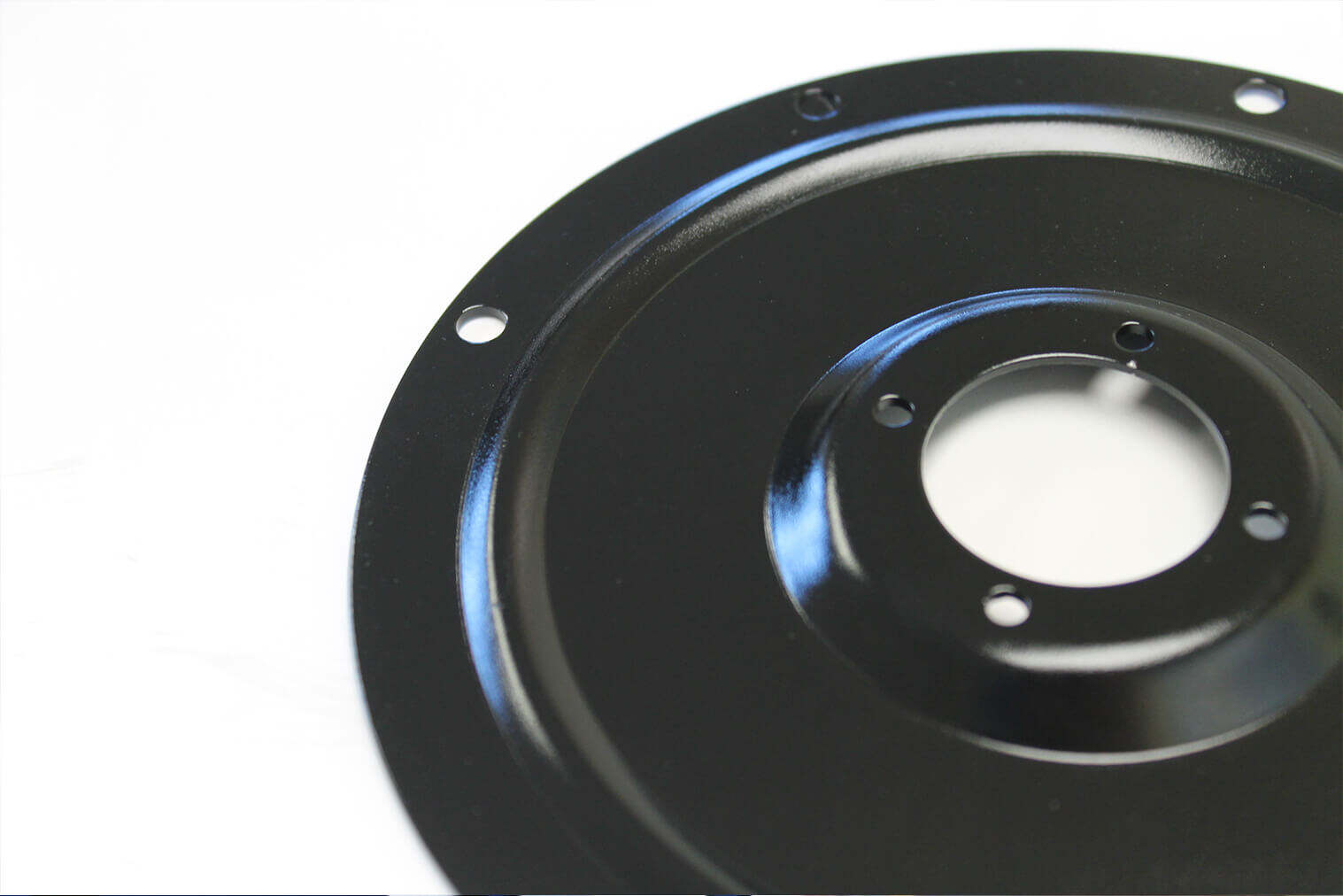
Valmiissa komponentissa sähkökemiallisesti pinnoitettu pinta tarkoittaa yleensä ohjattua, jatkuvaa kalvoa eikä käsin sovellettua ulkoasua. Kaupallisissa järjestelmissä käytetään yleisesti vesisoluja. PPG:n ja ScienceDirectin viitteet kuvaavat kylpyjä, jotka koostuvat suurelta osin deionoidusta vedestä, johon maalisaostumat on suspendoitu; tämä selittää, miksi prosessi tunnetaan tasaisuudestaan, alhaisesta huokoisuudestaan ja hyvästä korroosiosuojasta monimutkaisille osille. Joskus kyseinen kalvo toimii lopullisena pinnanpäällysteenä. Usein se toimii kestävänä alamaalina päällystekerroksen alla.
Nimi saattaa kuulostaa kemialliselta, mutta todellinen tarina liittyy liikkeeseen: varaukselliset hiukkaset kulkevat kylpyssä ja löytävät metallin yllättävän tarkasti.
Kuinka sähkökemiallinen pinnoitus laskee maalia sähkövirran avulla
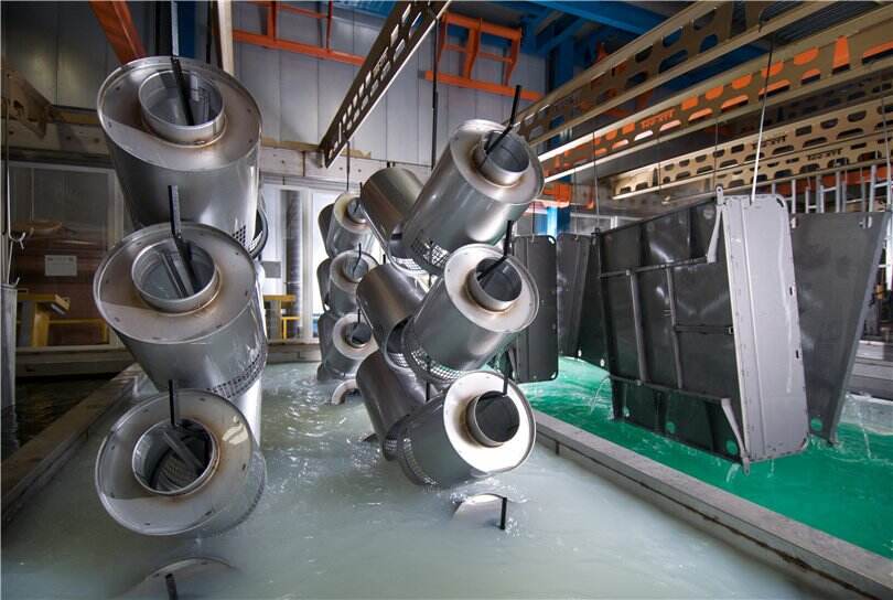
Kyseinen hiukkasliike on se, jossa määritelmä muuttuu todelliseksi prosessiksi. Sähkökemiallisessa pinnoituksessa maalia ei ainoastaan suihkuteta osaan. Metalliosan upotetaan vesisisältöiseen kylpyyn, ja sähkövirta ajaa pinnoitemateriaalin pinnalle. Prosessin selitykset Kluthe laserax, New Finish ja muut kuvaavat kylpyä deionoidulla vedellä, jossa on hienojakoisesti hajautettuja maalimateriaaleja, kuten harjattavia aineita, sidoksia ja väriaineita. Työpajan kielenkäytössä kyseessä on sähköinen maalikylpy, jossa on pieniä varattuja kiinteitä aineita, jotka odottavat sähkövirran saamista liikkumiseen.
Mitä elektroforeettinen pinnoitus on yksinkertaisissa termeissä
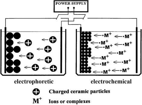
Osa täytyy olla sähkönjohteinen, koska se muodostaa sähköpiirin toisen puolen. Vastaelektrodi kylvyssä täydentää kyseisen piirin. Kun tasavirta kytketään päälle, vastakkaisesti varautuneet pinnoitushiukkaset alkavat liikkua nesteen läpi kohti metallipinnan suuntaan. Jotkut lukijat etsivät tätä mekanismia nimellä elektroforeettinen pinnoitus, mutta perusajatus on sama: varautuneet hiukkaset muuttavat paikkaansa nesteessä sähkökentän vaikutuksesta ja muodostavat sitten kalvon osaan.
- Puhdistettu metalliosa lasketaan kylpyyn, joka koostuu pääosin deionoidusta vedestä ja siinä suspendoituneista maalikiinteistä aineista.
- Tasavirtalähde luo sähkökentän osan ja vastaelektrodin välille.
- Varatut pinnoitushiukkaset liikkuvat kentän mukaisesti kohteeseen, koska vastakkaiset varaukset houkuttelevat toisiaan.
- Pinnan läheisyydessä elektrokemialliset reaktiot neutraloivat hiukkasten varauksen, mikä tekee pinnoituksesta vähemmän vesisoluista ja todennäköisemmin pysyvää metallipinnalla.
- Sedimentoitunut kerros alkaa muodostaa jatkuvaa kalvoa altistettujen alueiden yli.
- Kun tämä kalvo kasvaa, se muuttuu yhä sähköisemmin eristävämmäksi, joten sedimentaatio siirtyy kohti alueita, jotka ovat edelleen paljaita.
Miksi johtavat metallit houkuttelevat tasaisen kalvon muodostumista
Tasaisuus johtuu siitä, kuinka prosessi itse tasapainottaa deposition aikana. Sähkökenttä painaa hiukkasia alueille, joissa virta voi edelleen kulkea hyvin. Samalla pinnoitetut alueet muuttuvat vähemmän johtaviksi, kun kalvo kasvaa.
Koska tuore kalvo alkaa eristää pintaa, prosessi ohjaa luonnollisesti pinnoitusta kohti pinnoittamattomia syvyyskohtia, reunoja ja onteloita.
Tästä syystä elektroforeettista maalausta arvostetaan esimerkiksi kiinnikkeissä, leikkausosissa, kehyksissä ja muissa kulmia tai sisätiloja sisältävissä osissa. Kluthe ja Laserax molemmat korostavat tätä peittokykyä heittovoimana, mikä tarkoittaa, että järjestelmä pystyy saavuttamaan alueita, joita spray-menetelmillä on vaikea peittää tasaisesti.
Kuinka kylpykemia ja sähkökenttä luovat peiton
Kylpyyn tulee tehdä enemmän kuin vain maalin pitäminen. Sen on pidettävä pinnoitushiukkaset tasaisesti hajautettuina , mikä on syy siihen, miksi viitteet kuvailevat sitä kolloidaalisena suspensiona. Jatkuvalla kiertopumpulla estetään hiukkasten sadeutuminen, kun taas deionisoitu vesi rajoittaa sivuionien muodostumista, jotka voisivat häiritä kalvojen muodostumista. Kluthe huomauttaa, että epätoivottavat ionit voivat häiritä pinnoituksen pintaa, ja Laserax korostaa, että pH:n, lämpötilan ja kemiallisen tasapainon tulee olla tiukasti valvottuja johdonmukaisen sedimentoinnin varmistamiseksi. Prosessin aikana muodostuvat vastakkaismerkkiset ionit liikkuvat vastaelektrodiin ja niitä hallitaan suodatus- ja kiertosilmukoilla.
Eli tiede ei ole mysteerimäinen. Sähkökenttä antaa hiukkasille suunnan, ja kylpyyn liittyvä kemiallinen koostumus pitää niiden liikkeen riittävän vakautena, jotta muodostuu käyttökelpoinen pinakerros. Riippuu kaikista altaan ympäröivistä tekijöistä – puhdistuksesta ja esikäsittelystä pesuun ja kovettamiseen – siitä, muuttuuko tämä elegantti mekanismi luotettavaksi tuotantopinnaksi.
E-pinnoitusprosessilinjan vaihe vaiheelta
Tuotannossa altaan muodostaa vain yhden osan koko tarinasta. Hyvä sähköpinnoitustulos riippuu siitä, miltä osa näytti saapuessaan, mitä kosketti sitä ennen upottamista ja siitä, kuinka hyvin ylimääräinen maali kerätään takaisin ja kovetetaan sen jälkeen. Teollisuuden prosessiyhteenvetoja Laseraxilta ja Membraconilta kuvaavat linjaa ketjutettuna sarjana, ei yksittäisenä upotusvaiheena. Siksi sähköstaattisen sedimentointipinnoituksen linja rakennetaan yleensä valmistelun, sedimentoinnin, pesun ja kovettamisen ympärille, ja tarkastus on integroitu prosessivirtaan.
Pinnan valmistelu ennen E-pinnoitusprosessia
Tuoreet leikatut, koneistetut tai käsitellyt osat eivät yleensä saavu pinnoitettavaksi valmiiksi. Ne voivat sisältää öljyjä, tehdaslikaisuutta, metallihiukkasia tai okсидijäämiä. Jos nämä jäävät pinnalle, pinnoite voi menettää tarttuvuutensa tai näyttää puutteita myöhemmin.
- Saapuvien osien tarkastus: Varmista, että peruspinta on sähköjohteinen ja vapaana vakavista vaurioista, hitsauskipinöistä tai jumiutuneesta kontaminaatiosta.
- Puhdistus ja rasvanpoisto: Poista öljyt ja lika kemiallisella puhdistuksella, jotta pinnoite voi kiinnittyä raakametalliin eikä jäämiin.
- Huuhtelu: Huuhtele puhdistusaineen jäännökset pois. Membracon huomauttaa, että useita huuhteluvaiheita käytetään yleisesti ja että korkealaatuista vettä käytetään kemiallisten vaiheiden välissä.
- Muuntokäsittely tai esikäsittely: Fosfaatti- tai zirkoniumperustainen esikäsittely voi luoda paremman pohjan tarttuvuudelle ja korroosionkestävyydelle.
- Lopullinen huuhtelu: Jätä pinta kemiallisesti puhtaaksi ja valmiiksi upotettavaksi.
Tämä sähköpinnoituksen prosessin alkuosa ratkaisee usein sen, toimiiko myöhempäinen pinnoite suunnitellusti.
Sähköpinnoituksen linjalla tapahtuvat saostumis- ja huuhteluvaiheet
Kun osa on esikäsitelty, se siirtyy maalikylpyyn. Lähteet kuvaavat tätä kylpyä pääosin deionoidulla tai puhtaalla vedellä, johon on hajautettu maalisolidit. Laserax kuvaa tyypillistä kylpyä noin 85 prosenttia deionoitua vettä ja 15 prosenttia maalisolideja, kun taas Membracon kuvaa noin 80 prosenttia puhdasta vettä ja 20 prosenttia maalia. Kummassakin tapauksessa vesi toimii kantajanä, ja kemiallinen säätö pitää kylpyä vakaina.
- Säiliöimmersio: Osa upotetaan täysin veteen ja kytketään sähköisesti piirin osaksi.
- Jännitteen soveltaminen: Tasavirta ohjataan elektrodien kautta. Varatut maalihiukkaset liikkuvat metallille ja muodostavat pinnoitteen.
- Itserajoittuva pinnoituksen muodostuminen: Kun pinnoite kasvaa, se muuttuu yhä eristävämmäksi, joten saostuminen hidastuu, kun tavoiteltu pinnoitteen paksuus on saavutettu.
- Jälkipesu: Osa poistuu säiliöstä kuljettuaan kovettumatonta ylimääräistä maalia, jota kutsutaan usein mukana kuljetettavaksi maaliksi tai kermaispinnoitteeksi.
- Ultrafiltraatiorekuperointi: Pesun jälkeiset vaiheet käyttävät ultrafiltraattia tai permeaattia liiallisten materiaalien poistamiseen ja talteenotettavien maalipartikkelien palauttamiseen suljetussa kiertopiirissä, mikä korostetaan Membraconin ja Laseraxin toimesta.
Tämä talteenottokiertopiiri on tärkeä sekä pinnanlaadun yhdenmukaisuuden että materiaalitehokkuuden kannalta , erityisesti suuritehoisilla tuotantolinjoilla.
Kuivatus ja lopullinen tarkastus sähkökatalyyttisen sedimentoinnin jälkeen
Kosteana sedimentoitu kerros ei ole valmis, kun se poistuu pesuvaiheesta. Sen on vielä kuumennettava kestäväksi pinnoitteeksi.
- Uunikuivatus: Lämpö aiheuttaa ristiverkkoitumisen, joka muuttaa sedimentoidun kerroksen kovaksi, suojaavaksi pinnoitteeksi. Laserax mainitsee, että kuivatusajat ovat usein noin 20–30 minuuttia, ja monet teollisuusjärjestelmät käyttävät lämpötilaa noin 190 °C.
- Jäähdytys: Osalle annetaan jäähtyä ennen käsittelyä, pakkaamista tai mitään toissijaista prosessia.
- Lopputarkastus: Operaattorit tarkistavat peittävyyden, yhdenmukaisuuden ja ilmeiset viat ennen tuotteen vapauttamista tai päällystystä.
| Linjavaihe | Tarkoitus | Yleinen vianriski | Miksi vaihe on tärkeä |
|---|---|---|---|
| Saapuvan osan tila | Aloita pinnoitettavasta alustasta | Vauriot, voimakkaat likaisuudet, jäänyt lika | Huonot saapumisolmut kulkeutuvat osan mukana koko linjan läpi |
| Puhdistus | Poista öljy ja lika | Jäämäsaastuminen | Adheesio vaatii todellista metallikontaktia |
| Esikäsitys | Paranna korrosionkestävyyttä ja liittymistä | Heikko muuntokerroksen muodostuminen | Luo perustan pitkäaikaiselle suorituskyvylle |
| Pesu kylpyyn mennessä | Estää kemikaalien mukana kulkeutumista | Kylpyyn kontaminaatio | Suojaa kylpyä sen vakauden ja pinnoitteen laadun varmistamiseksi |
| Kylpyyn upotus ja jännite | Saada maali tasaisten kerrosten muodostumaan | Ohuet kohdat, epätasainen kerrosmuodostuma, ohitettujen syvennysten pinnallinen käsittely | Ytimen kalvon muodostuminen tapahtuu tässä |
| UF-jälkipesun talteenotto | Poista ylimääräinen maali ja talloa kiinteät ainekset | Pinnan jäännökset, jätteet, ulkonäön ongelmat | Pitää pinnan puhtaampana ja kiertoprosessin tehokkaampana |
| Kovettaminen ja jäähdytys | Ristiverkkoja ja vakauttaa pinnoitteen | Riittämätön kovetus, liiallinen kuumennus, käsittelyvauriot | Lopullinen kestävyys saadaan oikeasta kovutuksesta, ei pelkästään pinnoituksen muodostumisesta |
| Lopullinen tarkastus | Tarkista irrotuksen laatu | Huomattamatta jääneet virheet | Vahvistaa, että linja tuotti käyttökelpoisen pinnoituksen |
Sama prosessijärjestys, mutta eri asetukset tuottavat hyvin erilaisia tuloksia. Kalvopaksuus, jännite, pH-arvo, johtavuus, lämpötila ja kovettumisehdoilla on kaikilla merkittävä vaikutus siihen, mitä tämä linja todellisuudessa tuottaa osalle.
Muuttujat, jotka ohjaavat elektroforeettisen maalin laadun
Vaikka esikäsittelylinja olisi puhtaana ja vankka maaliallas vakaa, se ei vielä takaa vakaita tuloksia. Elektroforeettinen maali käyttäytyy kuin hallittu kemiallinen järjestelmä, joten pienetkin asetusten muutokset voivat vaikuttaa kalvopaksuuteen, ulkonäköön ja pitkäaikaiseen suojauskykyyn. Laseraxin ja Products Finishing -julkaisun prosessiohjeet osoittavat, että kalvopaksuuden pääsäätötekijöitä ovat sovellettu jännite, altaan kiinteän aineen pitoisuus ja altaan lämpötila, kun taas upotusaika ja pH-arvo toimivat usein toissijaisina säätötekijöinä. Toisin sanoen linjan riittää ei vain olla oikeassa järjestyksessä – sen on oltava myös oikeissa säätöikkunoissa.
Tärkeimmät muuttujat, jotka vaikuttavat elektroforeettisen maalin laatuun
Kalvopaksuus on helpoin paikka havaita tämä tasapaino. Products Finishing -julkaisu kuvaa tyypillisiä elektrokoatting-järjestelmiä 18–28 mikronin paksuisiksi, joissakin selkeän akryylin järjestelmissä jopa 8–10 mikronin paksuisiksi ja joissakin epoksi-järjestelmissä kovempia olosuhteita varten 35–40 mikronin paksuisiksi. Laserax sijoittaa useita korkean tuotannon linjoja 12,5–30 mikronin alueelle, laajemmat ala-, keski- ja raskasluokat ovat 12–25, 26–35 ja 36–50 mikronia. Tämä vaihteluväli on merkityksellinen, koska liian ohut kalvo voi jättää vähemmän suojaa altistetuille alueille, kun taas liiallinen kalvopaksuus voi aiheuttaa ulkonäön poikkeamia ja vaikeuttaa kovettumisen säätöä.
Kylpyyn liittyvä koostumus on yhtä tärkeä kuin sähköiset asetukset. Hakusanat 'elektroforeettisen pinnoituksen liuottimet eb pm pph' ja 'elektroforeettisen pinnoituksen liuotin eb pm pph' tulevat yleensä formulointitiedoista ja teknisistä asiakirjoista, eivätkä päivittäisistä ristikkojen vieressä tehtävistä päätöksistä. Tuotantolinjalla käytännöllinen kysymys on yksinkertaisempi: onko koliuottimen pitoisuus sellainen kuin toimittaja on sen määritellyt? Prosessin valvontaan liittyvä opas Robottimaalauksesta huomauttaa, että liian vähän liuotinta yhdessä katodisessa järjestelmässä voi heikentää vesisoluutta ja kalvon tasaisuutta, kun taas liian paljon liuotinta voi lisätä uudelleenliukoisuutta ja vesimerkin riskiä.
| Muuttuja | Mihin se vaikuttaa | Miten operoijat yleensä seuraavat sitä | Laatupoismaa, jos se poikkeaa hallinnasta |
|---|---|---|---|
| Kalvon paksuus | Peitto, korroosiosuojaus, päällystekannatin, osien sovitus | Kuivan kalvon mittaus, tarkistusnäytteet, syväntymäalueiden tarkistukset | Liian ohut kalvo voi aiheuttaa heikkoa peittoa, liian paksu kalvo taas voi aiheuttaa liiallista kalvopaksuutta ja ulkonäön vaihtelua |
| Käytetty jännite | Sedimentoitumisnopeus ja lopullinen kalvopaksuus | Tasasuuntaajan asetusarvo ja trenditallenteet | Alhainen jännite voi johtaa ohueen kalvoon, korkea jännite taas voi aiheuttaa ylimääräistä kalvopaksuutta ja joissakin järjestelmissä appelsiinikuoren kaltaista pinnanlaatua tai epätasaisen värin |
| Altaan kiintoaineet | Kalvopaksuuden muodostumisnopeus, kylpyveden vakaus, kalvon ulkonäkö | Tavallinen kylpyanalyysi ja kiinteän aineen määrän tarkastukset | Alhaiset kiinteän aineen määrät vähentävät kerrospaksuuden muodostumista, korkeammat kiinteän aineen määrät voivat lisätä kerrospaksuutta ja heikentää kylpyä stabiiliutta, jos niitä ei hallita |
| Kylpyn kemiallinen koostumus ja koliuottimet | Harjan liukoisuus, virtausominaisuudet, kylpyä stabiilius ja pinnan ulkonäkö | Toimittajan laboratoriotarkastukset, titraukset tai lisäysmerkintöjä, sekä formuloinnin valvonta | Sakkaantuminen, pisteet, huono virtaus, vesijäljet tai uudelleenliukoisuuden käyttäytyminen |
| pH | Sakkaantumiskäyttäytyminen, tuoreen kerroksen liukoisuus ja kylpyä stabiilius | pH-mittari ja tavallinen kylpyanalyysi | Liian alhainen pH voi voimistaa elektrolyysiä ja aiheuttaa neulapistoja; liian korkea pH voi heikentää vesisoluutuvuutta ja aiheuttaa sakkaantumista tai pisteitä joissakin järjestelmissä |
| Johtavuus | Ionikuorma, saastumisen taso ja sähkövirran vastaus | Johtavuusmittari kylpy- ja huuhteluvaiheissa | Epäpuhtausioneista johtuva johtavuuden nousu voi tehdä saostumasta aggressiivisempaa ja aiheuttaa rei’ityksiä tai ulkonäön muutoksia |
| Saostumisaika | Onko tavoitteellinen pinokerros saavutettu kokonaan | Kylpyajan mittari, kuljetinbeltin nopeus, linjan asetukset | Liian lyhyt aika voi jättää ohuen pinokerroksen, kun taas pidempi aika ei enää auta, kun järjestelmä on jo saavuttanut käytännöllisen pinokerroksen kasvurajan |
| Kylvyn lämpötila | Pinokerroksen paksuus, kylpyn ikääntyminen, liuotteen käyttäytyminen, ulkonäkö | Kylpyprobit, lämmönvaihtimen tarkastukset, lämpötilalokit | Korkeampi lämpötila voi lisätä pinokerroksen paksuutta ja nopeuttaa kylpyn ikääntymistä, alhaisempi lämpötila voi vaikuttaa ulkonäköön tai tasaisuuteen |
| Kovettumisaika ja kovettumislämpötila | Ristiverkottuminen, kovuus, kestävyys, lopullinen suojaus | Uuniasetukset, lämpötilatallenteet, kovettumisen varmistus | Epäriittävä kovettuminen voi heikentää suojatehokkuutta, liiallinen lämpö voi vaikuttaa joustavuuteen tai ulkoasuun |
Jännitteen, pH:n ja johtavuuden vaikutus sadeprosessiin
Jännite on suorin säätöparametri pinnoitteen paksuudelle. Products Finishing -julkaisu huomauttaa, että annetulla kiintoaineiden pitoisuudella ja kylpylämpötilalla korkeampi jännite lisää muodostuvan pinnoitteen määrää. Samassa lähteessä todetaan myös, että upotusaika auttaa ainoastaan silloin, kun osa ei ole vielä saavuttanut maksimipaksuutta, jonka jännite, kiintoaineiden pitoisuus ja lämpötila yhdessä mahdollistavat.
pH-arvo on hienovaraisempi tekijä, mutta sillä on silti merkitystä. Katodisissa järjestelmissä Products Finishing -julkaisu huomauttaa, että korkeampi pH-arvo voi lisätä pinnoitteen paksuutta, koska saostunut kerros kokee vähemmän happohyökkäystä permeaatiovaiheissa. Robotic Paint -yrityksen tarjoama tuotteenmäärittelyyn perustuva katodinen esimerkki antaa tarkemman kuvan tämän herkkyydestä: yhden koristeellisen järjestelmän pH-alue on 4,2–4,5, kiinteän aineen pitoisuus 10–12 prosenttia ja johtavuus noin 400–700 µS/cm. Tämä ei ole yleispätevä määritelmä, mutta se muistuttaa hyvin, että pH- ja johtavuusrajoitukset ovat kemiallisesti erityyppisiä ja niiden tulisi perustua pinnoitemateriaalin toimittajan suosituksiin eikä arvaamiseen.
Johtavuus kertoo yleensä ionisaasteista. Sama ohje antaa uudelleentäytettävän veden johtavuudeksi enintään 5 µS/cm ja viimeisen pesun ennen kylpyä enintään 10 µS/cm. Tämä on käytännöllinen viitepiste. Likainen pesuveden mukana kulkeutuminen ei vaikuta vain veden laatuun, vaan myös kylpyyn reagoimiseen.
Kuivatusolosuhteiden vaikutus lopullisen pinnoitteen suorituskykyyn
Sijoitettu kerros ei ole vielä valmis, kunnes lämpö muuttaa sen ristiverkottuneeksi kalvoksi. Laserax kuvaa useita teollisia kovettumisprosesseja noin 190 °C:n lämpötilassa 20–30 minuutin ajan. Toisenlaisen katodisen esimerkin Robotic Paint tarjoaa vaiheittaisen kuivatuksen, jossa esikuivatus tapahtuu 70–80 °C:ssa 10 minuutin ajan ja lopullinen kuumennus noin 170 °C:ssa 30 minuutin ajan. Nämä lukuarvot eivät sovi käytettäväksi eri järjestelmissä vaihdellen, mutta ne osoittavat tärkeän totuuden: kovettumisaikataulut ovat resiinikohtaisia.
Siksi kovettumisen säätö ei ole pelkästään uunin asetus, vaan se on kalvon suorituskykyyn vaikuttava asetus. Liian vähän lämpöä jättää pinnoitteen saavuttamatta täyttä ristiverkottumista. Liiallinen lämpö voi vaikuttaa ulkoasuun tai joustavuuteen. Lisäksi sama kylpyyn liittyvä muuttuja ei aina käyttäydy samalla tavalla eri järjestelmätyypeissä, mikä on juuri se kohta, jossa anodisen ja katodisen jakautuminen alkaa merkitä hyvin käytännöllistä eroa.
Anodinen vs. katodinen sähkökemiallinen pinnoitus
Napaisuus ei ole pieni asennusyksityiskohta elektrostaattisessa maalauksessa. Se muuttaa kemiallista reaktiota metallipinnalla, maalin tyyppiä, joka voi saostua, ja korroosiosuojan tasoa, jonka pinnoite voi todellisuudessa tarjota. Yksinkertaisissa termeissä katodiset järjestelmät tekevät kappaleesta negatiivisen, kun taas anodiset järjestelmät tekevät kappaleesta positiivisen. Tämä jakautuminen selittää, miksi kaksi eri linjaa voi käyttää molemmat elektroforeettista saostumamaalausta, mutta niiden käyttäytyminen käytössä voi olla hyvin erilaista.
Anodinen ja katodinen elektrostaattinen maalaus – perusteet
Lehti Products Finishing esittää eron selvästi: katodisessa elektrostaattisessa maalauksessa työkappale toimii katodina ja vetää puoleensa positiivisesti varautunutta polymeeriä. Anodisessa elektrostaattisessa maalauksessa työkappale toimii anodina ja vetää puoleensa negatiivisesti varautunutta polymeeriä. Veden elektrolyysi työkappaleella auttaa käynnistämään saostumista, mutta kyseessä on edelleen maalausprosessi, ei metallin pinnoitus. Harmaa menettää liukoisuutensa pinnalla ja muodostaa kalvon.
MISUMI kuvaa samaa jakoa kationisten ja anionisten järjestelmien avulla. Käytännön valmistuskielen mukaan sääntö on helppoa muistaa:
- Katodinen: osana toimii katodi ja maali on positiivinen.
- Anodinen: osana toimii anodi ja maali on negatiivinen.
Tämä yksittäinen valinta vaikuttaa pinnan hapettumiseen, kalvon ulkonäköön sekä siihen, kuinka voimakkaasti pinnoite suojaa pohjamateriaalia.
Milloin elektroforeettiset anodit vaikuttavat prosessin valintaan
Elektroforeettiset anodit ovat tärkeitä, koska hapetus tapahtuu positiivisesti varautuneessa osassa. Anodisessa sähkökylvysmenetelmässä tämä voi liuottaa joitakin metalli-ioneja pohjamateriaalista. Products Finishing huomauttaa, että nämä ionit voivat jäädä saostuneeseen kalvoon, mikä heikentää korroosiosuojaa ja voi aiheuttaa tahroja tai värinmuutoksia. Tämä on pääasiallinen syy, miksi anodisia järjestelmiä käytetään nykyään valikoivammin, kun korroosiosuojavaatimukset ovat korkeat.
Silti anoditeknologiaa on käytetty todellisissa sovelluksissa. Sama lähde huomauttaa, että joitakin anodisia akryylipinnoitteita voidaan käyttää vahvan värin ja kiilauksen säätöön, ja anodisia epoksi-pinnoitteita voidaan käyttää kohtalaisen hyvän korroosionkestävyyden saavuttamiseen tiukkoihin osiin, kuten valukappaleisiin ja moottorikoteloihin. Joitakin koostumuksia on myös käytetty siinä tapauksessa, että alhaisemmat kovettumislämpötilat ovat eduksi. MISUMI lisää hyödyllisen varoituksen pohjamateriaalista: anodijärjestelmiä ei yleensä käytetä kuparista, messingistä tai hopeapinnoitetuista esineistä, koska hapettuminen voi muuttaa näiden pintojen väriä.
Miten järjestelmätyyppi vaikuttaa korroosio- ja ulkonäköominaisuuksiin
| Järjestelmätyyppi | Sedimentointisuunta | Yleisimmät päätöksentekotekijät | Vahvuudet | Rajoitukset | Todennäköisempi soveltuvuus |
|---|---|---|---|---|---|
| Anodinen | Osa toimii positiivisena anodina. Negatiivisesti varautunut maali saostuu osaan. | Ulkonäön säätö, tiettyjä alhaisemman kovettumislämpötilan vaatimuksia, tiukat valukappaleet, kohtalainen korroosionkestävyysvaatimus. | Joissakin järjestelmissä voi tarjota taloudellisia pinnoitteita, joilla on erinomainen väri- ja kiilaukSENSäätö. Hyödyllinen joissakin valukappaleissa ja lämpöherkissä prosesseissa. | Oksidaatio osassa voi vetää metalli-ioneja pinnoitteen sisään, mikä vähentää korrosionkestävyyttä. Voi aiheuttaa tahroja tai värjäytymistä. Yleensä vältetään kuparista, messingistä ja hopeapinnoitetuista osista. | Valukappaleet, moottorilohkot ja sovellukset, joissa korrosionvaatimukset ovat merkittäviä, mutta eivät yhtä ankaria kuin auton rungon suojaus. |
| Katoodinen | Osa toimii negatiivisena katodina. Positiivisesti varautunut maali saostuu osaan. | Korkea korrosionkestävyys, käytetään autoissa ja kodinkoneissa, alamaalaukseen sopiva, pitkä käyttöikä. | Paljon vähemmän rautaa sisältyy pinnoitteeseen ja korrosionkestävyys on huomattavasti parempi. Välttää myös oksidaation aiheuttamaa värjäytymistä osan pinnalla. | Sekametalliohjelmat voivat vaatia erityistä esikäsittelyä, erityisesti kun alumiini ja teräs käyttävät samaa kylpyä. Koristeellinen ulkonäkö ei välttämättä ole ainoa suunnittelun prioriteetti. | Autoteollisuus, kodinkoneet ja korrosiolle herkät metalliosat, joissa yleensä määritellään korkean suorituskyvyn sähkökemiallinen pinnoitus. |
Useimmissa kysytyimmistä ohjelmissa katodinen sähkökatalyyttinen pinnoitus on tullut standardiksi, koska korrosionkestävyys yleensä voittaa määrittelyjen keskustelun. Anodiset järjestelmät säilyvät merkityksellisinä silloin, kun ulkonäkö, pohjamateriaalin herkkyys tai tietty kovettamisstrategia muuttaa laskelmaa. Parempi kysymys ei ole, kumpi järjestelmä on uudempi, vaan kumpi sopii parhaiten osan metalliin, käyttöympäristöön ja pintakäsittelyn tehtävään.
Tämä pintakäsittelyn tehtävä on tärkeämpi kuin aluksi saattaa vaikutaa, sillä vaikka oikea napaisuus valittaisiinkin, e-pinnan ei automaattisesti tarvitse olla oikea pinnoitusperhe. Jotkut osat hyötyvät siitä välittömästi. Toisia palvelee paremmin täysin erilainen pinnoitusmenetelmä.
Missä E-pintaus soveltuu ja missä se ei sovellu
Katodinen järjestelmä voi olla oikean napaisuuden omaava, mutta silti väärän pintakäsittelyperheen edustaja. Joukossa sähkökatalyyttisiä pinnoituksia , e-pinnoite on vahvin, kun osa on sähkönjohtava metalli, muoto on vaikea suihkuttaa ja korroosiosuojaus on saavutettava myös näkyvän ulkopinnan ulkopuolelle.
Parhaiten sopivat sovellukset e-pinnoitteelle
E-pinnoite on yleensä hyvin sopiva, kun ohjelmassa vaaditaan ohutta, tasaisesti jakautunutta ja toistettavissa olevaa kalvoa sähkönjohtaville metalliosille. Käytännössä se on järkevin vaihtoehto silloin, kun tarvitset:
- Kattavuutta syvennyksissä, onteloissa, kulmissa ja muissa vaikeakulmaisissa geometrioissa.
- Korroosiosuojaa koko kosteuden altistamalle pinnalle, ei ainoastaan helposti saavutettaville alueille.
- Suurtehoinen käsittely tarkasti ohjatulla ja tasaisella kalvonmuodostumisella.
- Yhtenäinen, esimaalimainen peruspinta ennen jauhepinnoitetta tai nestemäistä päällystystä.
- Päättyvä pinnoite osille, kuten alustakomponenteille, kiinnikkeille, jousituskomponenteille tai muille korroosioaltisille laitteille.
Juuri tämä yhdistelmä on syynä siihen, miksi menetelmä on säilynyt yleisenä autoteollisuuden ja teollisen metallipinnankäsittelyn alalla. Jos pinnoitteen tehtävänä on ensisijaisesti suojata ja vasta toissijaisesti koristella, sähkökemiallinen pinnoitus (e-pinnoitus) pääsee usein lyhyen ehdokasluettelon kärkeen.
Vaihtoehtoiset pinnoitukset saattavat olla parempi valinta
Ei kaikki osat vaadi sähköisesti saadun kalvon muodostamaa pinnoitetta. Elemet kuvailee autoforeettinen pinnoitus immuusiomenetelmänä, joka perustuu kemialliseen reaktioon eikä sähkövirran käyttöön. Tämä muuttaa päätöksentekoa. Menetelmä voi olla houkutteleva, kun tärkeitä ovat alhaisempi kuumennuslämpötila, pienempi prosessitilavaatimus, vahva reunasuojaus tai koottujen rautapitoisten osien käsittely, joissa on kumia tai muovia. Samassa lähteessä mainitaan kuumennusnoin 104 °C:n lämpötilassa ja korostetaan, että jotkin ruuvikierreosat eivät ehkä vaadi suojausta.
Jauhepinnoitus voi myös olla parempi ratkaisu, kun geometria on yksinkertaisempi ja vaatimukset painottavat paksua, kestävämpää ja värimuunneltavampaa pintaa.
Heikosti sopivat tapaukset sähkökatalyyttiseen pinnoitukseen (e-coat) perustuvat yleensä sen omiin vahvuuksiin. Jos pääalusta ei ole sähkönjohteinen, jos ohjelma vaatii paksua koristellun pinnoituksen rakennetta tai jos visuaalisen pinnan joustavuus on tärkeämpi kuin syvien koverteiden peittäminen, toinen menetelmä saattaa olla käytännöllisempi. Joitakin ostajia käyttävät epätarkasti ilmaisua sähköpinnoitus kaikille sähköavusteisille maalausprosesseille, mutta fiksuimman kysymyksen tulee aina olla sama: mitä tehtävää pinta-aineen todella tulee suorittaa?
Autoforeettisen pinnoituksen ja muiden vaihtoehtojen vertailu
| Pinnan perhe | Peitto monimutkaisessa geometriassa | Reunasuorituskyky | Korroosiosuojauslogiikka | Ulkoasun joustavuus | Johtavuusvaatimus | Yhteensopivuus toissijaisen viimeistelyn kanssa |
|---|---|---|---|---|---|---|
| E-pinnoite | Erittäin tehokas syvällisissä alueissa, onteloissa ja johtavien metalliosien sisäpinnalla | Yhtenäinen kokonaispintakäsittely, jossa mainitut lähteet korostavat syvyyden saavuttamista enemmän kuin reunakohtaista etua | Ohut, tasaisesti muodostunut suojakalvo, jota valitaan usein silloin, kun korrosionkestävyys tai alusmaalin tehtävä on ratkaiseva | Kohtalainen itsenäisenä pinnakäsittelynä, vahva yhtenäisenä peruskerroksena | Kyllä, osan on oltava sähköjohteinen ja toimia elektrodina | Hyvä soveltuvuus alusmaaliksi jauhe- tai nestemäisten päällysteiden alla |
| Autoforeettinen pinnoitus | Vahva upotuskattavuus monimutkaisilla rautapitoisilla osilla sekä joissakin koottujen metalli- ja ei-metalliyhdistelmien osilla | Elemet korostaa erityisesti poikkeuksellista reunansuojaa ja vähentynyttä peittelyä joissakin kierreosissa | Suojakalvo muodostuu kemiallisella reaktiolla rautapitoisella metallilla ja tarjoaa hyvän korrosionkestävyyden | Toiminnallisempi kuin erityisen koristeellinen mainitussa vertailussa | Sähkövirtaa ei vaadita, mutta reaktio liittyy rautapitoisiin metalleihin | Mainittu sopivaksi tapauksiin, joissa pinnoitettuihin osiin saattaa olla tarvetta muokkaustoimenpiteille pinnoituksen jälkeen |
| Jauhemaalaus | Paras yksinkertaisemmissa ja avoimemmissa geometrioissa; etua ei ole yhtä suurta syvissä koloissa kuin sähkökatalyyttisessa pinnoituksessa (e-coat) | Paksumpi kalvo voi lisätä kestävyyttä, mutta mainittu vertailu ei esitä sitä kolojen peittämisessä johtavana menetelmänä | Este- suojaus paksuemmasta kovennetusta kalvosta, mutta GAT pitää sähkökatalyyttistä pinnoitusta (e-coat) edullisimpana maksimaaliseen korrosiosuojaan monimutkaisissa osissa | Korkea, erityisesti silloin, kun värien vaihto ja erikoisvärien sävyt ovat tärkeitä | Sovelletaan staattisella sähkövarauksella maadoitettuihin osiin mainitussa prosessikuvausssa | Valitaan usein näkyväksi pinnaksi, kun paksuus, kestävyys ja värivalikoima määrittävät vaatimukset |
Yksikään rivi ei voita jokaista kategoriaa. Hyvin valittu pinnoite vastaa metallia, geometriaa, käyttöympäristöä sekä sitä, onko pinnoite lopullinen ulkoasukerros vai suojakanta.
Laatukontrolli elektroforeettisessa prosessissa
Hyvin valittu pinnoite voi silti epäonnistua tuotantolinjalla, jos kontrollipisteet ovat heikkoja. Elektroforeettisessa prosessissa elektroforeettisessa prosessissa , pinnoitteen säiliö saa suurimman osan huomiosta, mutta laatu yleensä paranee tai heikkenee aiemmin – puhdistus-, huuhtelu- ja esikäsittelyvaiheessa. Käytännön ohjeet esikäsittelylähteistä ja Laseraxilta viittaavat samaan malliin: adheesiohäviö, kraaterit, neulapisteet, epätasainen peittävyys ja varhainen korroosio johtuvat usein saastumisesta, muiden aineiden mukana kulkeutumisesta, epävakaoista kylpyolosuhteista tai kovettumisen poikkeamista. Tämä tekee laatukontrollista vähemmän yhtä lopullista tarkastusta ja enemmän linjakohtaista kontrollisuunnitelmaa.
Esikäsittelytarkastukset, jotka estävät pinnoitusvirheet
Ensimmäinen tavoite on yksinkertainen: antaa pinnoitteelle puhtaaksi ja kemiallisesti yhtenäiseksi metallipinnaksi. Puhdistusvaiheita on tarkistettava niiden kemiallisen voimakkuuden, lämpötilan, vaikutusajan ja kattavuuden osalta. Pesuvedet pitäisi poistaa puhdistusaineen jäämät eikä siirtää niitä eteenpäin prosessissa. Myös muuntokäsittelyn laatu on tärkeää, sillä huonosti muodostunut kerros voi jäädä heikoksi perustaksi sekä tarttumiselle että korroosionkestävyydelle.
Yksi hyödyllinen vertailuarvo löydettävissä lopullisen deionoidun pesuveden ohjeista, jossa suositellaan pitävän lopullisen deionoidun pesuveden johtavuus alle 50 µS/cm ennen sähkökemiallista pinnoitusta. Tämä ei ole yleispätevä arvo kaikille tuotantolinjoille, mutta se osoittaa, kuinka tiukasti pesuveden puhtautta saattaa joutua säätämään. Tarkat rajat on aina otettava pinnoitemateriaalin toimittajan, asiakkaan eritelmien ja tehtaan prosessidokumenttien mukaan.
Prosessimääritelmät sähkökemiallisessa pinnoituksessa
Aikana sähköfoboreettinen pinnoitus , jatkuvuus on tärkeämpää kuin yksittäinen onnistunut käsittely. Prosessin aikaiset valvontatoimet sähdepitoisade keskittyvät yleensä kylpykemian, pH-arvon, johtavuuden, lämpötilan, kiinteän aineen tasapainon, sekoituksen, jännitteen, ajan ja osien sijoittelun valvontaan. Tavoitteena on pitää pinnoitteen paksuus ja peitto vakiona, myös syvällä sijaitsevissa alueissa. Visuaaliset tarkastukset pesun jälkeen ovat myös hyödyllisiä, koska ne voivat paljastaa ilmeisiä ohuita kohtia, liiallista jäännöstä tai ulkonäön muutoksia ennen kuin kovettuminen lukitsee virheet paikoilleen.
| Tarkastuspiste | Mitä tarkistaa | Mahdollinen muutoksen syy | Korjaava toimintasuunta |
|---|---|---|---|
| Puhdistusvaihe | Puhdistimen pitoisuus, lämpötila, suihkutus- tai upotuskattavuus, vaikutusaika | Kylpyyn kuluminen, alhainen lämpötila, huono suihkupäätoiminta, liian lyhyt aika | Palauta kylpykemia, varmista laitteiston suorituskyky, vahvista suunniteltu altistumisaika |
| Pesu ja lopullinen deionisoitu vesipesu | Veden laatu, johtavuus, mukana kulkeutuvat epäpuhtauudet, jääneet jäännökset | Saastunut pesuvesi, huono vastavirtaus, riittämätön pesu | Päivitä huuhtelun ohjaus, vähennä mukana kulkeutumista ja varmista lopullisen huuhtelun puhtaus hyväksyttyjen rajojen mukaisesti |
| Konversiopinnoite | Peittävyys, kylpytilan tila, reaktion tasaisuus | Epätasapainoinen kemiallinen koostumus, liete, saastuminen, riittämätön kosketusaika | Säädä kemiallista koostumusta toimittajan ohjeiden mukaisesti ja varmista muuntumislaadun tarkistukset |
| E-maalin kylpyyn liittyvä huolto | pH-arvo, johtavuus, lämpötila, kiinteät aineet, kiertäminen ja sekoittaminen | Saastuminen, heikko täydennys, epävakaa kylpytilan tasapaino | Seuraa kylpytilan kehitystä, suodata ja palauta kemiallinen koostumus sekä tutki mahdollista ylävirtaisesta mukana kulkeutumisesta aiheutuvaa ongelmaa |
| Sedimentointiasetukset | Jännite, sedimentointiaika, sähköinen kosketus, ripustusasento | Tasasuuntimen poikkeama, huono maadoitus, peittäminen kosketuspisteissä, geometriaongelmat | Tarkista sähköinen asennus, paranna kiinnitys, vahvista asetukset prosessiikkunan mukaan |
| Jälkipesu ja talteenotto | Jäännöspainta, pesun puhtaustaso, talteenottosilmukan suorituskyky | Heikko pesu, ylikuormitettu talteenottosysteemi, saastuminen | Stabiloi pesuvaiheet ja varmista, että talteenotettu materiaali ei aiheuta uusia virheitä |
| Keraamiakkuutus | Kuivatusuunin aika, kuivatusuunin lämpötila, osan lämpötila, ilmavirran tasaisuus | Epäriittävä kovettuminen, liiallinen kuumennus, kylmät alueet, linjan nopeuden muutokset | Vahvista kovettumisprofiili hyväksytyn kuumennusohjelman mukaisesti ja seuraa todellista osan lämpötilaa |
| Lopullinen tarkastus | Kalvon paksuus, ulkonäkö, tarttuvuus, tarvittaessa korroosiotestien tulokset | Aiemmin linjassa havaitsematon prosessin poikkeama, käsittelyvauriot, kovettumisvaihtelut | Sulje epäluotettavat osat pois käytöstä, jäljitä poikkeama ensimmäiseen epäonnistuneeseen tarkastuspisteeseen, korjaa ennen uudelleenkäynnistystä |
Kovettumisen jälkeinen tarkastus ja vianestäminen
Kovettumisen jälkeen pinnoitteen ulkonäköä ja toimintaa on tarkastettava. ASTM-standardien mukaiset laatuohjeet korostavat yhtenäistä paksuutta, tarttuvuuden varmistamista ja ympäristösuorituskyvyn tarkastuksia luotettavan valvontajärjestelmän keskeisinä osina. Tarkastusmenetelmä vaihtelee osan ja käyttöolosuhteiden mukaan, mutta tarkastuksen tulisi ainakin erottaa esteettiset ongelmat todellisista suojauksen riskeistä.
- Alaston paikat: usein liittyvät huonoon puhdistukseen, heikkoön sähköiseen kontaktiin, ilmakuplien jäämiseen tai ripustuslaitteen aiheuttamaan häiriöön.
- Heikko tarttuvuus: yleensä liittyy jääneeseen öljyyn, heikkoonsa muuntokerrokseen, pesuveden saastumiseen tai riittämättömään kovettumiseen.
- Epätasainen pinnoite: usein johtuu jännitteen epävakaudesta, kylpyyn liittyvästä epätasapainosta, johtavuuden poikkeamasta tai osan huonosta asennosta.
- Kosmeettiset pinnanongelmat: kraaterit, neulapisteet, karkeus, tahrat tai vesijäljet voivat viitata saastumiseen, siirtymään tai kylpyveden epävakauteen.
- Korroosioon liittyvät huolenaiheet: ohut peitekerros, esikäsittelyn epäonnistuminen tai vaurioitunut kalvo voivat johtaa myöhemmin käytössä ilmeneviin kupliin, irtoamiseen tai kalvon alla esiintyvään ruostumiseen.
Kun nämä tarkastuspisteet dokumentoidaan ja niiden kehitystä seurataan, tuotantolinjasta tulee luotettavampi. Ostajille ja insinööreille tämä jäljitettävyys kertoo yhtä paljon valmistusvalmiudesta kuin itse pinnoitekin.
Autoteollisuuden ostajien sähkökemiallisesti pinnoitettujen osien hankinta
Jäljitettävyys muuttuu hankintakysymykseksi heti, kun pinnoitteen hyväksyntä siirtyy näytteestä sarjatuotantoon. Autoteollisuuden tiimejä, jotka ostavat sähkökemiallisesti pinnoitettuja osia , tulee tarkistaa toimittajan arviointi laajemmin kuin pelkästään maalikylvyn osalta. Pinnankäsittelyohjeet shaoyi huomauttaa, että koneistus-, puristus-, valumuotti- ja muovausmenetelmät voivat johtaa erilaisiin käsittelyvalintoihin ja varmistussuunnitelmiin. Käytännössä tämä tarkoittaa, että osan geometria, terävien reunojen hallinta, hitsaustila, esikäsittely ja kovettuminen kuuluvat kaikki samaan hankintakeskusteluun.
Mitä kysyä valmistuspartnerilta E-pinnakäsittelyn valmiudesta
Monille OEM- ja Tier 1 -ohjelmille IATF 16949 on käytännössä perusedellytys, ja sama autoteollisuuden laatukehys edellyttää vahvaa APQP-, PPAP-, FMEA-, MSA- ja SPC-menetelmien käyttöä. Kun toimittaja väittää tarjoavansa sähkökoating pinnakäsittelyä, ostajien tulisi kysyä, miten kyseinen pinnakäsittely hallitaan kokonaisessa käynnistysprosessissa, ei ainoastaan sitä, onko linja olemassa.
- Osan suunnittelutuki: Voiko tiimi tunnistaa tyhjennysreiät, ripustuspisteet, terävät reunat ja geometriaan liittyvät ongelmat ennen työkalujen lopullista vahvistamista?
- Puristus- ja CNC-kyvykkyydet: Voivatko he hallita ylävirtaan sijaitsevaa metalliprosessia, joka vaikuttaa lopulliseen e-pinnakäsittelyyn tulos?
- Esikäsittelyn ja pinnankäsittelyn koordinointi: Kuinka ne vastaavat perusmetallin, esikäsittelyn ja pinnoitusten vaatimuksia?
- Laadun dokumentointi: Voivatko ne tukea APQP- ja PPAP-paketteja, ohjaussuunnitelmia, tarkastustietueita ja asiakasspesifisiä vaatimuksia?
- Prototyyppituki: Voivatko ne toimittaa nopeita prototyyppejä tai kokeiluosia ennen täysmittaista tuotantokäynnistystä?
- Tuotannon skaalautuvuutta: Voiko sama laatusysteemi kattaa tehtävän kokonaisuudessaan – alkaen validointirakentelusta ja päättyen sarjatuotantoon?
Miksi yhden tukipisteen metalliosien tuotanto vähentää siirtoja
Erilliset toimittajat voivat edelleen onnistua, mutta jokainen lisäsiirto lisää mahdollisuutta poikkeamille. Teräspätkäongelma saattaa ilmetä myöhemmin liimausongelmana. Suunnittelun yksityiskohta saattaa olla ristiriidassa ripustusjärjestelmän kanssa vasta kun PPAP-osat on valmistettu. Yhden tukipisteen koordinointi lyhentää yleensä palautteiden kiertoa ja tekee juurisyyvastuun selvemmäksi käynnistyksen ja muutoshallinnan aikana.
Milloin Shaoyi on käytännöllinen ratkaisu automaali-ohjelmiin
Juuri siellä Shaoyi voi olla käytännöllinen vaihtoehto tarkistettavaksi muiden pätevien lähteiden rinnalla. Yritys esittelee itsensä yhden tukipisteen autoteollisuuden metalliosien valmistajana, jolla on 15 vuoden kokemus leimattujen osien, CNC-koneistuksen, nopean prototyypin valmistuksen ja pinnankäsittelyn koordinaation alalla; autoteollisuustyön osalta korostetaan IATF 16949 -sertifiointia. Ostajille, jotka haluavat vähentää aukkoja osien valmistuksen ja viimeistelyn välillä, tämä integroitu malli voi olla hyödyllinen jo varhaisista näytteistä alkaen suurten sarjojen pinnoitettujen osien ohjelmiin saakka. Lopulta vahvin toimittaja on se, joka pystyy selittämään koko prosessin reitin, ei ainoastaan pinnoituskohdan.
Elektroforeettisesti pinnoitetut osat – usein kysytyt kysymykset
1. Mitä elektroforeettisesti pinnoitettu tarkoittaa valmiissa osassa?
Se tarkoittaa yleensä sitä, että metalliosaan on saatu maalikalvo vedenperäisessä upotuskylvyssä, jossa sähkövirta siirtää varattuja pinnoitushiukkasia pinnalle. Insinööreille ja ostajille tämä viittaa yleensä hallittuun ja tasaiseen pinnoitustulokseen, joka peittää sekä avoimet pinnat että vaikeapääsyisemmät alueet yhtenäisemmin kuin monet manuaaliset suihkutusmenetelmät.
2. Onko e-pinnoitus sama kuin sähköpinnoitus ja elektrodeposiitio?
Useimmissa valmistuskäytöissä kyllä. E-pinnoitus on yleinen tehdaskäytössä käytetty lyhenne, sähköpinnoitus on selkeä kielenkäyttöinen nimitys ja elektrodeposiitio on laajempi tekninen termi saman pinnoitusperheen kuvaamiseen. Nämä sanat käytetään usein vaihtoehtoisesti, mutta todellinen spesifikaatio riippuu edelleen yksityiskohtaisista asioista, kuten anodisesta tai katodisesta kemiallisesta koostumuksesta, esikäsittelystä, halutusta kalvon paksuudesta ja kovettamisvaatimuksista.
3. Miksi e-pinnoitusta valitaan usein monimutkaisille metallimuodoille?
E-pintakäsittely toimii hyvin monimutkaisissa johtavissa osissa, koska sähkökenttä auttaa siirtämään pinnoitemateriaalia syvyyksiin, kulmiin ja onteloihin, jotka ovat vaikeampia peittää tasaisesti pelkällä suihkutuksella. Kun pinnan kerros kasvaa, jo pinnoitetut alueet muuttuvat vähemmän aktiivisiksi, mikä mahdollistaa jäljelle jääneiden paljaisten alueiden jatkuvan peittymisen. Siksi kiinnikkeet, kehykset ja muut geometrisesti monimutkaiset osat ovat yleisiä e-pintakäsittelyn kohdeosia.
4. Mikä on anodisen ja katodisen e-pintakäsittelyn ero?
Ero alkaa napaisuudesta. Anodisissa järjestelmissä kappale toimii anodina. Katodisissa järjestelmissä se toimii katodina. Tämä muuttaa pintareaktiota saostumisen aikana, mikä puolestaan vaikuttaa pohjamateriaalin käyttäytymiseen, ulkoasuun ja korroosionkestävyyteen. Katodisia järjestelmiä suositaan laajalti vaativissa korroosionsuojatehtävissä, kun taas anodisia järjestelmiä voidaan edelleen käyttää valituissa sovelluksissa, joissa niiden prosessiominaisuudet vastaavat kappaleen ja käyttövaatimusten tarpeita.
5. Mitä autoteollisuuden ostajien tulisi tarkistaa ennen elektroforeettisesti pinnoitettujen osien hankintaa?
Ostajien tulisi varmistaa koko tuotantoprosessi, eikä pelkästään kysyä, onko toimittajalla elektroforeesipinnoitustankki. Tärkeimmät tarkistukset kattavat esimerkiksi valssaus- tai koneistusvaiheen valvonnan, esikäsittelyn hallinnan, kylpyjen huollon, kovettumisen validoinnin, jäljitettävyyden sekä autoteollisuuden dokumentaation, kuten APQP- ja PPAP-dokumentaation. Monille ohjelmille on tärkeää, että toimittaja täyttää IATF 16949 -standardin vaatimukset. Jos käsien välisiä siirtoja halutaan vähentää, kannattaa harkita integroitua toimittajaa, kuten Shaoyia, sillä se yhdistää autoteollisuuden metalliosien valmistuksen, nopean prototyypityksen ja pinnankäsittelyn koordinoinnin yhteen laadunvarmistukseen perustuvaan työnkulkuun.